EP3869550A2 - Heat sink load balancing apparatus - Google Patents
Heat sink load balancing apparatus Download PDFInfo
- Publication number
- EP3869550A2 EP3869550A2 EP20206923.3A EP20206923A EP3869550A2 EP 3869550 A2 EP3869550 A2 EP 3869550A2 EP 20206923 A EP20206923 A EP 20206923A EP 3869550 A2 EP3869550 A2 EP 3869550A2
- Authority
- EP
- European Patent Office
- Prior art keywords
- coupled
- load
- anchor
- support
- heat sink
- Prior art date
- Legal status (The legal status is an assumption and is not a legal conclusion. Google has not performed a legal analysis and makes no representation as to the accuracy of the status listed.)
- Granted
Links
Images




Classifications
-
- H—ELECTRICITY
- H10—SEMICONDUCTOR DEVICES; ELECTRIC SOLID-STATE DEVICES NOT OTHERWISE PROVIDED FOR
- H10W—GENERIC PACKAGES, INTERCONNECTIONS, CONNECTORS OR OTHER CONSTRUCTIONAL DETAILS OF DEVICES COVERED BY CLASS H10
- H10W40/00—Arrangements for thermal protection or thermal control
- H10W40/60—Securing means for detachable heating or cooling arrangements, e.g. clamps
- H10W40/641—Snap-on arrangements, e.g. clips
-
- G—PHYSICS
- G06—COMPUTING OR CALCULATING; COUNTING
- G06F—ELECTRIC DIGITAL DATA PROCESSING
- G06F1/00—Details not covered by groups G06F3/00 - G06F13/00 and G06F21/00
- G06F1/16—Constructional details or arrangements
- G06F1/20—Cooling means
-
- H—ELECTRICITY
- H05—ELECTRIC TECHNIQUES NOT OTHERWISE PROVIDED FOR
- H05K—PRINTED CIRCUITS; CASINGS OR CONSTRUCTIONAL DETAILS OF ELECTRIC APPARATUS; MANUFACTURE OF ASSEMBLAGES OF ELECTRICAL COMPONENTS
- H05K7/00—Constructional details common to different types of electric apparatus
- H05K7/20—Modifications to facilitate cooling, ventilating, or heating
- H05K7/2039—Modifications to facilitate cooling, ventilating, or heating characterised by the heat transfer by conduction from the heat generating element to a dissipating body
- H05K7/20409—Outer radiating structures on heat dissipating housings, e.g. fins integrated with the housing
-
- G—PHYSICS
- G06—COMPUTING OR CALCULATING; COUNTING
- G06F—ELECTRIC DIGITAL DATA PROCESSING
- G06F1/00—Details not covered by groups G06F3/00 - G06F13/00 and G06F21/00
- G06F1/16—Constructional details or arrangements
- G06F1/20—Cooling means
- G06F1/203—Cooling means for portable computers, e.g. for laptops
-
- H—ELECTRICITY
- H05—ELECTRIC TECHNIQUES NOT OTHERWISE PROVIDED FOR
- H05K—PRINTED CIRCUITS; CASINGS OR CONSTRUCTIONAL DETAILS OF ELECTRIC APPARATUS; MANUFACTURE OF ASSEMBLAGES OF ELECTRICAL COMPONENTS
- H05K1/00—Printed circuits
- H05K1/02—Details
- H05K1/0201—Thermal arrangements, e.g. for cooling, heating or preventing overheating
- H05K1/0203—Cooling of mounted components
- H05K1/0204—Cooling of mounted components using means for thermal conduction connection in the thickness direction of the substrate
-
- H—ELECTRICITY
- H05—ELECTRIC TECHNIQUES NOT OTHERWISE PROVIDED FOR
- H05K—PRINTED CIRCUITS; CASINGS OR CONSTRUCTIONAL DETAILS OF ELECTRIC APPARATUS; MANUFACTURE OF ASSEMBLAGES OF ELECTRICAL COMPONENTS
- H05K7/00—Constructional details common to different types of electric apparatus
- H05K7/20—Modifications to facilitate cooling, ventilating, or heating
- H05K7/2029—Modifications to facilitate cooling, ventilating, or heating using a liquid coolant with phase change in electronic enclosures
- H05K7/20336—Heat pipes, e.g. wicks or capillary pumps
-
- H—ELECTRICITY
- H05—ELECTRIC TECHNIQUES NOT OTHERWISE PROVIDED FOR
- H05K—PRINTED CIRCUITS; CASINGS OR CONSTRUCTIONAL DETAILS OF ELECTRIC APPARATUS; MANUFACTURE OF ASSEMBLAGES OF ELECTRICAL COMPONENTS
- H05K7/00—Constructional details common to different types of electric apparatus
- H05K7/20—Modifications to facilitate cooling, ventilating, or heating
- H05K7/2039—Modifications to facilitate cooling, ventilating, or heating characterised by the heat transfer by conduction from the heat generating element to a dissipating body
- H05K7/20409—Outer radiating structures on heat dissipating housings, e.g. fins integrated with the housing
- H05K7/20418—Outer radiating structures on heat dissipating housings, e.g. fins integrated with the housing the radiating structures being additional and fastened onto the housing
-
- H—ELECTRICITY
- H05—ELECTRIC TECHNIQUES NOT OTHERWISE PROVIDED FOR
- H05K—PRINTED CIRCUITS; CASINGS OR CONSTRUCTIONAL DETAILS OF ELECTRIC APPARATUS; MANUFACTURE OF ASSEMBLAGES OF ELECTRICAL COMPONENTS
- H05K7/00—Constructional details common to different types of electric apparatus
- H05K7/20—Modifications to facilitate cooling, ventilating, or heating
- H05K7/2039—Modifications to facilitate cooling, ventilating, or heating characterised by the heat transfer by conduction from the heat generating element to a dissipating body
- H05K7/205—Heat-dissipating body thermally connected to heat generating element via thermal paths through printed circuit board [PCB]
-
- H—ELECTRICITY
- H10—SEMICONDUCTOR DEVICES; ELECTRIC SOLID-STATE DEVICES NOT OTHERWISE PROVIDED FOR
- H10W—GENERIC PACKAGES, INTERCONNECTIONS, CONNECTORS OR OTHER CONSTRUCTIONAL DETAILS OF DEVICES COVERED BY CLASS H10
- H10W40/00—Arrangements for thermal protection or thermal control
- H10W40/60—Securing means for detachable heating or cooling arrangements, e.g. clamps
-
- H—ELECTRICITY
- H10—SEMICONDUCTOR DEVICES; ELECTRIC SOLID-STATE DEVICES NOT OTHERWISE PROVIDED FOR
- H10W—GENERIC PACKAGES, INTERCONNECTIONS, CONNECTORS OR OTHER CONSTRUCTIONAL DETAILS OF DEVICES COVERED BY CLASS H10
- H10W40/00—Arrangements for thermal protection or thermal control
- H10W40/60—Securing means for detachable heating or cooling arrangements, e.g. clamps
- H10W40/611—Bolts or screws
-
- H—ELECTRICITY
- H10—SEMICONDUCTOR DEVICES; ELECTRIC SOLID-STATE DEVICES NOT OTHERWISE PROVIDED FOR
- H10W—GENERIC PACKAGES, INTERCONNECTIONS, CONNECTORS OR OTHER CONSTRUCTIONAL DETAILS OF DEVICES COVERED BY CLASS H10
- H10W40/00—Arrangements for thermal protection or thermal control
- H10W40/20—Arrangements for cooling
- H10W40/231—Arrangements for cooling characterised by their places of attachment or cooling paths
-
- H—ELECTRICITY
- H10—SEMICONDUCTOR DEVICES; ELECTRIC SOLID-STATE DEVICES NOT OTHERWISE PROVIDED FOR
- H10W—GENERIC PACKAGES, INTERCONNECTIONS, CONNECTORS OR OTHER CONSTRUCTIONAL DETAILS OF DEVICES COVERED BY CLASS H10
- H10W40/00—Arrangements for thermal protection or thermal control
- H10W40/60—Securing means for detachable heating or cooling arrangements, e.g. clamps
- H10W40/625—Clamping parts not primarily conducting heat
-
- H—ELECTRICITY
- H10—SEMICONDUCTOR DEVICES; ELECTRIC SOLID-STATE DEVICES NOT OTHERWISE PROVIDED FOR
- H10W—GENERIC PACKAGES, INTERCONNECTIONS, CONNECTORS OR OTHER CONSTRUCTIONAL DETAILS OF DEVICES COVERED BY CLASS H10
- H10W40/00—Arrangements for thermal protection or thermal control
- H10W40/70—Fillings or auxiliary members in containers or in encapsulations for thermal protection or control
- H10W40/73—Fillings or auxiliary members in containers or in encapsulations for thermal protection or control for cooling by change of state
Definitions
- a heat dissipating apparatus is generally mounted on a heat load, such that a portion of the surface of the heat dissipating apparatus is mounted on, and thus in thermal and mechanical contact with, the heat load.
- the portion of the surface of the heat dissipating apparatus that is mounted on the heat load is referred to in this specification as the mounting surface.
- Each anchor of an anchor-spring mount has two ends: a first end that connects to an anchor point, which is typically the surface where the anchor connects to, e.g., a printed circuit board, and a second end that is coupled to the heat dissipating apparatus.
- the forces exerted by the springs on the heat dissipating apparatus allows the mounting surface of the heat dissipating apparatus to maintain a desired contact pressure over the heat load.
- This specification relates to an apparatus that enables a heat dissipating apparatus (e.g., a heat sink, a cold plate, etc.), which can be mounted on a heat load (e.g., a hot component of an electronic assembly), to exert even (or uniform) force over the heat load.
- a heat dissipating apparatus e.g., a heat sink, a cold plate, etc.
- a heat load e.g., a hot component of an electronic assembly
- one innovative aspect of the subject matter described in this specification can be embodied in systems that include a heat sink base that can be thermally coupled to a heat load, the heat sink base defining a top side and a bottom side, wherein the bottom side defines a mounting surface that can be physically coupled to the heat load; a support that is pivotally coupled by a pivot couple to the top surface of the heat sink base; at least a first anchor and a second anchor, wherein: the first anchor has a first end and a second end, wherein the first end connects to a first anchor point, and the second end is coupled to a first load surface of the support by a first spring; the second anchor has a first end and a second end, wherein the first end connects to a second anchor point, and the second end is coupled to a second load surface of the support by a second spring; and the first load surface and the second load surface are symmetrically disposed on opposite sides of the pivot couple; wherein the pivot couple is centrally located relative to the mounting surface of the heat sink base
- the pivot couple can include a joint coupled to the top surface of the heat sink, wherein the joint can be centrally located relative to the mounting surface; and the support can be coupled to the joint, wherein the support is configured to pivot about the joint.
- the support can be integrated with the joint, the first spring, and the second spring.
- the system can include a load plate coupled to the top surface of the heat sink base; wherein the pivot couple can be a rod that is coupled to the load plate at a position that is central relative to the mounting surface, wherein: the rod is perpendicular to the load plate; the rod includes an opening that receives a joint into which the support is inserted, wherein the support is configured to pivot along an axis that is perpendicular to the rod and that is parallel to the mounting surface.
- a load plate coupled to the top surface of the heat sink base can include a pressure sensor coupled to the top surface of the heat sink base; the load plate coupled to the pressure sensor, wherein the pressure sensor measures force exerted by the load plate on the top surface of the heat sink base.
- the support can be integrated with the first spring and the second spring.
- a rod that is coupled to the load plate at a position that is central to the mounting surface can include: a swivel coupled to the load plate at a position that is central to the mounting surface; and the rod coupled to the swivel, wherein the rod can rotate independently of the load plate about the swivel.
- each of the first anchor and the second anchor can pass through a respective opening in the support and the heat sink.
- the innovations described in this specification enable a heat dissipating apparatus that utilizes anchor-spring mounts to exert an even (or uniform) force distribution over the mounting surface in comparison to conventional heat dissipating apparatuses that utilize an anchor-spring mounting approach.
- Spring properties e.g., the spring constant
- Such variation can lead to differences in spring loads between identical anchor-spring mounts in conventional heat dissipating apparatuses that utilize such anchor-spring mounts.
- Spring loads can also vary due to differences in the anchors' heights caused by differences in the anchors' relative displacement into, e.g., a printed circuit board, into which each anchor is secured. Such variation in spring loads in turn leads to an uneven (or non-uniform) force distribution over the entire mounting surface in conventional heat dissipating apparatuses.
- innovations described in this specification enable even (or uniform) force distribution over the entire mounting surface by using a support and pivot couple (as further described in this specification) in conjunction with the anchor-spring mounts, that together compensate for the uneven force distribution caused by, e.g., the varying spring loads and/or the different relative displacement of the anchors.
- the following description describes the structure and operation of a heat sink apparatus that utilizes a pivot couple and support in conjunction with anchor-spring mounts to enable the heat sink apparatus to exert an even (or uniform) amount of force over the entire portion of the heat sink apparatus that is thermally and/or mechanically in contact with a heat load.
- a heat sink apparatus other types of heat dissipating apparatuses can be used instead of the heat sink.
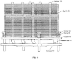
- Figure 1 is a side view 100 of an apparatus that uses a pivot couple and a support in conjunction with anchor spring mounts to mount a heat sink to a heat load.
- the apparatus shown in Figure 1 includes a heat sink that has multiple heat fins 102, which are connected (e.g., soldered) to heat pipes 102. Each heat pipe 102 is attached to the heat sink base 112.
- the heat sink base 112 is thermally and mechanically coupled to a heat load 114.
- the apparatus uses anchor-spring mounts to mount the heat sink base onto the heat load.
- the apparatus shown in Figure 1 includes four anchor-spring mounts (only three of which are visible in Figure 1 ), i.e., four anchors 106 and four springs 108. Each spring 108 that is connected to one end of a respective anchor 106, is coupled to a support 110.
- the heat sink of Figure 1 includes four anchor-spring mounts, additional or fewer anchor-spring mounts can be used.
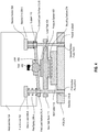
- Figure 2 is a block diagram 200 of a first implementation of the pivot couple and support that are utilized in mounting the heat sink base onto a heat load as shown in Figure 1 .
- the heat sink base 112 is mounted on, and thus is mechanically and thermally coupled to, a heat load 114.
- the heat sink base 112 has a top side (also referred to as surface) and a bottom side.
- the bottom side defines a mounting surface 214 that is physically coupled to (i.e., in contact with) the heat load 114.
- a support 110 is pivotally coupled by a pivot couple to the top surface of the heat sink base 112.
- the pivot couple in the block diagram 200 is a joint 206, which is affixed to the top surface of the heat sink base 112 at a location that is central relative to the mounting surface 214 of the heat sink base 112.
- the heat sink base 112 is mounted onto the heat load 114 using anchor-spring mounts.
- the block diagram 200 shows two anchor-spring mounts: (1) a first anchor 202 and a first spring 206-A and (2) a second anchor 204 and a second spring 206-B.
- Each of the first anchor 202 and the second anchor 204 has a first end 208-B and a second end 208-A.
- the first end 208-B of each of the anchors (202 and 204) is affixed to a printed circuit board (PCB) 214 at a first anchor point 210-A and a second anchor point 210-B, respectively.
- PCB printed circuit board
- each of the anchors 202 and 204 pass through a respective opening in the heat sink base 112.
- these anchors 202 and 204 may be designed with a dent or a curve that enables these anchors to be mounted to the printed circuit board 214 without having to pass through the heat sink base 112.
- a first spring 206-A is affixed to the second end 208-A of the first anchor 202
- a second spring 206-B is affixed to the second end 208-A of the second anchor 204.
- the first spring 206-A rests on the support 110 at a first load surface 212-A and the second spring 206-B rests on the support 110 at a second load surface 212-B.
- the second end 208-A of the first anchor 202 is coupled to the first load surface 212-A of the support 110
- the second end 208-B of the second anchor 204 is coupled to the second load surface 212-A of the support 110.
- the first load surface 212-A and the second load surface 212-B are symmetrically disposed on opposite sides of the joint 206.
- Spring loads of the first spring 206-A and the second spring 206-B impart forces onto the load surfaces of the support 110. Any unevenness in the spring forces causes the support 110 to pivot about the joint 206, but nevertheless results in the spring forces being normally transferred by the joint 206 for even distribution over the mounting surface 214. Thus, even if the resulting spring loads of the first spring 206-A and the second spring 206-B on the support 110 vary, an even (or uniform) amount of force is distributed over the mounting surface.
- Figure 3 is a block diagram 300 of a second implementation of the pivot couple and support that are utilized in mounting the heat sink base onto a heat load as shown in Figure 1 .
- the block diagram 300 has the same operation as the apparatus shown in Figure 2 . Even the structural aspects of the apparatus shown in block diagram 300 are the same as those shown in Figure 2 , with one exception. Unlike Figure 2 in which the springs 206-A and 206-B, the joint 206, and the support 110 are discrete (and separate) components, these pieces are integrated into one component in Figure 3 as a support with integrated joint and springs 312. In some implementations, the support can be integrated with the springs 206-A and 206-B, but may not be integrated with the joint 206. In such implementations, the joint 206 is a separate from the support that is integrated with the springs.
- Integrating the support with the joint and/or the springs can help reduce the cost of the apparatus because the resulting, integrated support could be produced using a single manufacturing process (as opposed to a separate manufacturing process for each of the multiple components, which is likely to be more expensive than the cost of producing a single component).
- Figure 4 is a block diagram 400 of a third implementation of the pivot couple and support that are utilized in mounting the heat sink base onto a heat load as shown in Figure 1 .
- the block diagram 400 has the same operation as the apparatus shown in Figure 2 . Even the structural aspects of the apparatus shown in block diagram 400 are generally the same as those shown in Figure 2 , with the exception that (1) the pivot couple of Figure 4 is different from the pivot couple (i.e., a joint 206) shown and described with reference to Figure 2 and (2 )
- Figure 4 also includes a load plate 404 and a pressure sensor 406. The following description provides additional details about the pivot couple of Figure 4 as well as the load plate 404 and the pressure sensor 406.
- the load plate 404 is coupled to the top surface of the heat sink base 112. As shown in Figure 4 , the load plate 404 is affixed to a pressure sensor 406, which in turn is affixed to the top surface of the heat sink base 112.
- the pressure sensor 406 measures, and thus enables monitoring of, the force exerted by the load plate on the top surface of the heat sink base 112. In some implementations, the pressure sensor 406 may not be used, in which case, the load plate 404 may be directly coupled to the top surface of the heat sink base 112.
- the pivot couple in Figure 4 comprises a rod 402 and joint 408.
- the rod 402 is coupled to the load plate 404, e.g., by screwing the rod 402 into the load plate 404.
- the rod 402 includes an opening that receives the joint 408.
- the support 110 is inserted into the joint 408 and is configured to pivot along an axis that is perpendicular to the rod 402 and that is parallel to the mounting surface 214.
- the rod 402 can be directly coupled to the top surface of the heat sink base 112, e.g., by screwing the rod 402 into the top surface of the heat sink base 112.
- Figure 5 is a block diagram 500 of a fourth implementation of the pivot couple and support that are utilized in mounting the heat sink base onto a heat load as shown in Figure 1 .
- the block diagram 500 has the same operation as the apparatus shown in Figure 4 . Even the structural aspects of the apparatus shown in Figure 5 are the same as those shown in Figure 4 , with one exception. Unlike Figure 4 in which the springs 206-A and 206-B, and the support 110 are discrete (and separate) components, these pieces are integrated into one component in Figure 5 , as a support with integrated springs 502.
- Figure 6 is a block diagram 600 of a fifth implementation of the pivot couple and support that are utilized in mounting the heat sink base onto a heat load as shown in Figure 1 .
- the block diagram 600 has the same operation as the apparatus shown in Figure 4 . Even the structural aspects of the apparatus shown in block diagram 600 are the same as those shown in Figure 4 , with one exception.
- the block diagram 600 includes a swivel 602 that is coupled (e.g., affixed) to the load plate 404 and then the rod 402 is coupled to (e.g., screwed onto) the swivel 602.
- the swivel 602 enables the rod 402 to rotate about the swivel, independently of the load plate 404.
- some implementations may not utilize a load plate 404.
- the swivel 602 is coupled to the top surface of the heat sink base 112, and the rod 402 is then coupled to the swivel 602 such that the rod 402 can rotate about the swivel, independently of the heat sink base 112.
- the anchor-spring mounting approach described with reference to Figures 2-6 can be implemented using a base other than a heat sink base.
- the heat dissipating apparatus need not be a heat sink.
- a heat sink apparatus that utilizes a pivot couple and support with anchor-spring mounts to enable exertion of a uniform amount of force over the mounting surface of the apparatus that is thermally/physically coupled to a heat load.
- the apparatus can include a heat sink base that has a bottom side defining the mounting surface, and a top side to which a support is pivotally coupled by a pivot couple.
- the apparatus can include a first and second anchor that each have a first end connected to an anchor point and a second end coupled to a load surface on the support by a spring.
- the load surfaces can be symmetrically disposed on opposite sides of the pivot couple, which is centrally located relative to the mounting surface so that the force imparted by spring loads of the springs is evenly distributed over the mounting surface.
Landscapes
- Engineering & Computer Science (AREA)
- Physics & Mathematics (AREA)
- Microelectronics & Electronic Packaging (AREA)
- Theoretical Computer Science (AREA)
- Thermal Sciences (AREA)
- Human Computer Interaction (AREA)
- General Engineering & Computer Science (AREA)
- General Physics & Mathematics (AREA)
- Computer Hardware Design (AREA)
- Cooling Or The Like Of Semiconductors Or Solid State Devices (AREA)
- Cooling Or The Like Of Electrical Apparatus (AREA)
Abstract
Description
- A heat dissipating apparatus is generally mounted on a heat load, such that a portion of the surface of the heat dissipating apparatus is mounted on, and thus in thermal and mechanical contact with, the heat load. The portion of the surface of the heat dissipating apparatus that is mounted on the heat load is referred to in this specification as the mounting surface.
- To achieve good thermal and/or mechanical contact between the heat dissipating apparatus and the heat load, some implementations utilize anchor-spring mounts. Each anchor of an anchor-spring mount has two ends: a first end that connects to an anchor point, which is typically the surface where the anchor connects to, e.g., a printed circuit board, and a second end that is coupled to the heat dissipating apparatus. The forces exerted by the springs on the heat dissipating apparatus allows the mounting surface of the heat dissipating apparatus to maintain a desired contact pressure over the heat load.
- This specification relates to an apparatus that enables a heat dissipating apparatus (e.g., a heat sink, a cold plate, etc.), which can be mounted on a heat load (e.g., a hot component of an electronic assembly), to exert even (or uniform) force over the heat load.
- In general, one innovative aspect of the subject matter described in this specification can be embodied in systems that include a heat sink base that can be thermally coupled to a heat load, the heat sink base defining a top side and a bottom side, wherein the bottom side defines a mounting surface that can be physically coupled to the heat load; a support that is pivotally coupled by a pivot couple to the top surface of the heat sink base; at least a first anchor and a second anchor, wherein: the first anchor has a first end and a second end, wherein the first end connects to a first anchor point, and the second end is coupled to a first load surface of the support by a first spring; the second anchor has a first end and a second end, wherein the first end connects to a second anchor point, and the second end is coupled to a second load surface of the support by a second spring; and the first load surface and the second load surface are symmetrically disposed on opposite sides of the pivot couple; wherein the pivot couple is centrally located relative to the mounting surface of the heat sink base so that a force imparted by spring loads of the first and second springs is normally transferred to the mounting surface for even distribution over the mounting surface.
- These and other embodiments can each optionally include one or more of the following features.
- In some implementations, the pivot couple can include a joint coupled to the top surface of the heat sink, wherein the joint can be centrally located relative to the mounting surface; and the support can be coupled to the joint, wherein the support is configured to pivot about the joint.
- In some implementations, the support can be integrated with the joint, the first spring, and the second spring.
- In some implementations, the system can include a load plate coupled to the top surface of the heat sink base; wherein the pivot couple can be a rod that is coupled to the load plate at a position that is central relative to the mounting surface, wherein: the rod is perpendicular to the load plate; the rod includes an opening that receives a joint into which the support is inserted, wherein the support is configured to pivot along an axis that is perpendicular to the rod and that is parallel to the mounting surface.
- In some implementations, a load plate coupled to the top surface of the heat sink base can include a pressure sensor coupled to the top surface of the heat sink base; the load plate coupled to the pressure sensor, wherein the pressure sensor measures force exerted by the load plate on the top surface of the heat sink base.
- In some implementations, the support can be integrated with the first spring and the second spring.
- In some implementations, a rod that is coupled to the load plate at a position that is central to the mounting surface can include: a swivel coupled to the load plate at a position that is central to the mounting surface; and the rod coupled to the swivel, wherein the rod can rotate independently of the load plate about the swivel.
- In some implementations, each of the first anchor and the second anchor can pass through a respective opening in the support and the heat sink.
- Particular embodiments of the subject matter described in this specification can be implemented to realize one or more of the following advantages. For example, the innovations described in this specification enable a heat dissipating apparatus that utilizes anchor-spring mounts to exert an even (or uniform) force distribution over the mounting surface in comparison to conventional heat dissipating apparatuses that utilize an anchor-spring mounting approach. Spring properties (e.g., the spring constant) can vary across multiple iterations of the same spring because of variations in, e.g., material composition, manufacturing, batch, and tolerances. Such variation can lead to differences in spring loads between identical anchor-spring mounts in conventional heat dissipating apparatuses that utilize such anchor-spring mounts. Spring loads can also vary due to differences in the anchors' heights caused by differences in the anchors' relative displacement into, e.g., a printed circuit board, into which each anchor is secured. Such variation in spring loads in turn leads to an uneven (or non-uniform) force distribution over the entire mounting surface in conventional heat dissipating apparatuses. In contrast, and as further described in this specification, the innovations described in this specification enable even (or uniform) force distribution over the entire mounting surface by using a support and pivot couple (as further described in this specification) in conjunction with the anchor-spring mounts, that together compensate for the uneven force distribution caused by, e.g., the varying spring loads and/or the different relative displacement of the anchors.
- The details of one or more embodiments of the subject matter described in this specification are set forth in the accompanying drawings and the description below. Other features, aspects, and advantages of the subject matter will become apparent from the description, the drawings, and the claims.
-
-
Figure 1 is a side view of an apparatus that uses a pivot couple and a support in conjunction with anchor spring mounts to mount a heat sink to a heat load. -
Figure 2 is a block diagram of a first implementation of the pivot couple and support that are utilized in mounting the heat sink base onto a heat load as shown inFigure 1 . -
Figure 3 is a block diagram of a second implementation of the pivot couple and support that are utilized in mounting the heat sink base onto a heat load as shown inFigure 1 . -
Figure 4 is a block diagram of a third implementation of the pivot couple and support that are utilized in mounting the heat sink base onto a heat load as shown inFigure 1 . -
Figure 5 is a block diagram of a fourth implementation of the pivot couple and support that are utilized in mounting the heat sink base onto a heat load as shown inFigure 1 . -
Figure 6 is a block diagram of a fifth implementation of the pivot couple and support that are utilized in mounting the heat sink base onto a heat load as shown inFigure 1 . - Like reference numbers and designations in the various drawings indicate like elements.
- The following description describes the structure and operation of a heat sink apparatus that utilizes a pivot couple and support in conjunction with anchor-spring mounts to enable the heat sink apparatus to exert an even (or uniform) amount of force over the entire portion of the heat sink apparatus that is thermally and/or mechanically in contact with a heat load. Although the below descriptions are with reference to a heat sink apparatus, other types of heat dissipating apparatuses can be used instead of the heat sink.
-
Figure 1 is a side view 100 of an apparatus that uses a pivot couple and a support in conjunction with anchor spring mounts to mount a heat sink to a heat load. - The apparatus shown in
Figure 1 includes a heat sink that hasmultiple heat fins 102, which are connected (e.g., soldered) toheat pipes 102. Eachheat pipe 102 is attached to theheat sink base 112. Theheat sink base 112 is thermally and mechanically coupled to aheat load 114. The apparatus uses anchor-spring mounts to mount the heat sink base onto the heat load. The apparatus shown inFigure 1 includes four anchor-spring mounts (only three of which are visible inFigure 1 ), i.e., fouranchors 106 and four springs 108. Each spring 108 that is connected to one end of arespective anchor 106, is coupled to asupport 110. Although the heat sink ofFigure 1 includes four anchor-spring mounts, additional or fewer anchor-spring mounts can be used. - Details about the structure and operation of the different implementations of the pivot couple and support that are deployed in conjunction with the anchor-spring mounts is described below with reference to
Figures 2-6 . -
Figure 2 is a block diagram 200 of a first implementation of the pivot couple and support that are utilized in mounting the heat sink base onto a heat load as shown inFigure 1 . - As shown in the block diagram 200, the
heat sink base 112 is mounted on, and thus is mechanically and thermally coupled to, aheat load 114. Theheat sink base 112 has a top side (also referred to as surface) and a bottom side. The bottom side defines amounting surface 214 that is physically coupled to (i.e., in contact with) theheat load 114. - A
support 110 is pivotally coupled by a pivot couple to the top surface of theheat sink base 112. The pivot couple in the block diagram 200 is ajoint 206, which is affixed to the top surface of theheat sink base 112 at a location that is central relative to themounting surface 214 of theheat sink base 112. - The
heat sink base 112 is mounted onto theheat load 114 using anchor-spring mounts. The block diagram 200 shows two anchor-spring mounts: (1) afirst anchor 202 and a first spring 206-A and (2) asecond anchor 204 and a second spring 206-B. Each of thefirst anchor 202 and thesecond anchor 204 has a first end 208-B and a second end 208-A. The first end 208-B of each of the anchors (202 and 204) is affixed to a printed circuit board (PCB) 214 at a first anchor point 210-A and a second anchor point 210-B, respectively. As shown inFigure 1 , each of theanchors heat sink base 112. However, in some implementations, theseanchors circuit board 214 without having to pass through theheat sink base 112. - A first spring 206-A is affixed to the second end 208-A of the
first anchor 202, and a second spring 206-B is affixed to the second end 208-A of thesecond anchor 204. - The first spring 206-A rests on the
support 110 at a first load surface 212-A and the second spring 206-B rests on thesupport 110 at a second load surface 212-B. In this manner, the second end 208-A of thefirst anchor 202 is coupled to the first load surface 212-A of thesupport 110, and the second end 208-B of thesecond anchor 204 is coupled to the second load surface 212-A of thesupport 110. As shown in block diagram 200, the first load surface 212-A and the second load surface 212-B are symmetrically disposed on opposite sides of thejoint 206. - Spring loads of the first spring 206-A and the second spring 206-B impart forces onto the load surfaces of the
support 110. Any unevenness in the spring forces causes thesupport 110 to pivot about thejoint 206, but nevertheless results in the spring forces being normally transferred by the joint 206 for even distribution over themounting surface 214. Thus, even if the resulting spring loads of the first spring 206-A and the second spring 206-B on thesupport 110 vary, an even (or uniform) amount of force is distributed over the mounting surface. -
Figure 3 is a block diagram 300 of a second implementation of the pivot couple and support that are utilized in mounting the heat sink base onto a heat load as shown inFigure 1 . - The block diagram 300 has the same operation as the apparatus shown in
Figure 2 . Even the structural aspects of the apparatus shown in block diagram 300 are the same as those shown inFigure 2 , with one exception. UnlikeFigure 2 in which the springs 206-A and 206-B, the joint 206, and thesupport 110 are discrete (and separate) components, these pieces are integrated into one component inFigure 3 as a support with integrated joint and springs 312. In some implementations, the support can be integrated with the springs 206-A and 206-B, but may not be integrated with the joint 206. In such implementations, the joint 206 is a separate from the support that is integrated with the springs. Integrating the support with the joint and/or the springs can help reduce the cost of the apparatus because the resulting, integrated support could be produced using a single manufacturing process (as opposed to a separate manufacturing process for each of the multiple components, which is likely to be more expensive than the cost of producing a single component). -
Figure 4 is a block diagram 400 of a third implementation of the pivot couple and support that are utilized in mounting the heat sink base onto a heat load as shown inFigure 1 . - The block diagram 400 has the same operation as the apparatus shown in
Figure 2 . Even the structural aspects of the apparatus shown in block diagram 400 are generally the same as those shown inFigure 2 , with the exception that (1) the pivot couple ofFigure 4 is different from the pivot couple (i.e., a joint 206) shown and described with reference toFigure 2 and (2 )Figure 4 also includes aload plate 404 and apressure sensor 406. The following description provides additional details about the pivot couple ofFigure 4 as well as theload plate 404 and thepressure sensor 406. - The
load plate 404 is coupled to the top surface of theheat sink base 112. As shown inFigure 4 , theload plate 404 is affixed to apressure sensor 406, which in turn is affixed to the top surface of theheat sink base 112. Thepressure sensor 406 measures, and thus enables monitoring of, the force exerted by the load plate on the top surface of theheat sink base 112. In some implementations, thepressure sensor 406 may not be used, in which case, theload plate 404 may be directly coupled to the top surface of theheat sink base 112. - The pivot couple in
Figure 4 comprises arod 402 and joint 408. Therod 402 is coupled to theload plate 404, e.g., by screwing therod 402 into theload plate 404. Therod 402 includes an opening that receives the joint 408. Thesupport 110 is inserted into the joint 408 and is configured to pivot along an axis that is perpendicular to therod 402 and that is parallel to the mountingsurface 214. In implementations where aload plate 404 is not used, therod 402 can be directly coupled to the top surface of theheat sink base 112, e.g., by screwing therod 402 into the top surface of theheat sink base 112. -
Figure 5 is a block diagram 500 of a fourth implementation of the pivot couple and support that are utilized in mounting the heat sink base onto a heat load as shown inFigure 1 . - The block diagram 500 has the same operation as the apparatus shown in
Figure 4 . Even the structural aspects of the apparatus shown inFigure 5 are the same as those shown inFigure 4 , with one exception. UnlikeFigure 4 in which the springs 206-A and 206-B, and thesupport 110 are discrete (and separate) components, these pieces are integrated into one component inFigure 5 , as a support withintegrated springs 502. -
Figure 6 is a block diagram 600 of a fifth implementation of the pivot couple and support that are utilized in mounting the heat sink base onto a heat load as shown inFigure 1 . - The block diagram 600 has the same operation as the apparatus shown in
Figure 4 . Even the structural aspects of the apparatus shown in block diagram 600 are the same as those shown inFigure 4 , with one exception. The block diagram 600 includes aswivel 602 that is coupled (e.g., affixed) to theload plate 404 and then therod 402 is coupled to (e.g., screwed onto) theswivel 602. Theswivel 602 enables therod 402 to rotate about the swivel, independently of theload plate 404. - As noted with reference to
Figure 5 , some implementations may not utilize aload plate 404. In such implementations, theswivel 602 is coupled to the top surface of theheat sink base 112, and therod 402 is then coupled to theswivel 602 such that therod 402 can rotate about the swivel, independently of theheat sink base 112. - In some implementations, the anchor-spring mounting approach described with reference to
Figures 2-6 can be implemented using a base other than a heat sink base. In such implementations, the heat dissipating apparatus need not be a heat sink. - According to implementations, there is provided a heat sink apparatus that utilizes a pivot couple and support with anchor-spring mounts to enable exertion of a uniform amount of force over the mounting surface of the apparatus that is thermally/physically coupled to a heat load. The apparatus can include a heat sink base that has a bottom side defining the mounting surface, and a top side to which a support is pivotally coupled by a pivot couple. The apparatus can include a first and second anchor that each have a first end connected to an anchor point and a second end coupled to a load surface on the support by a spring. The load surfaces can be symmetrically disposed on opposite sides of the pivot couple, which is centrally located relative to the mounting surface so that the force imparted by spring loads of the springs is evenly distributed over the mounting surface.
- While this specification contains many specific implementation details, these should not be construed as limitations on the scope of any features or of what may be claimed, but rather as descriptions of features specific to particular embodiments. Certain features that are described in this specification in the context of separate embodiments can also be implemented in combination in a single embodiment. Conversely, various features that are described in the context of a single embodiment can also be implemented in multiple embodiments separately or in any suitable subcombination. Moreover, although features may be described above as acting in certain combinations and even initially claimed as such, one or more features from a claimed combination can in some cases be excised from the combination, and the claimed combination may be directed to a subcombination or variation of a subcombination.
- Thus, particular embodiments of the subject matter have been described. Other embodiments are within the scope of the following claims. In some cases, the actions recited in the claims can be performed in a different order and still achieve desirable results. In addition, the processes depicted in the accompanying figures do not necessarily require the particular order shown, or sequential order, to achieve desirable results. In certain implementations, multitasking and parallel processing may be advantageous.
Claims (17)
- A system comprising:a heat sink base that can be thermally coupled to a heat load, the heat sink base defining a top side and a bottom side, wherein the bottom side defines a mounting surface that can be physically coupled to the heat load;a support that is pivotally coupled by a pivot couple to the top side of the heat sink base;at least a first anchor and a second anchor, wherein:the first anchor has a first end and a second end, wherein the first end connects to a first anchor point, and the second end is coupled to a first load surface of the support by a first spring;the second anchor has a first end and a second end, wherein the first end connects to a second anchor point, and the second end is coupled to a second load surface of the support by a second spring; andthe first load surface and the second load surface are symmetrically disposed on opposite sides of the pivot couple;wherein the pivot couple is centrally located relative to the mounting surface of the heat sink base so that a force imparted by spring loads of the first and second springs is normally transferred to the mounting surface for even distribution over the mounting surface.
- The system of claim 1, wherein:the pivot couple comprises a joint coupled to the top side of the heat sink base, wherein the joint is centrally located relative to the mounting surface; andthe support is coupled to the joint, wherein the support is configured to pivot about the joint.
- The system of claim 1 or 2, further comprising:a load plate coupled to the top side of the heat sink base;wherein the pivot couple is a rod that is coupled to the load plate at a position that is central relative to the mounting surface, wherein:the rod is perpendicular to the load plate;the rod includes an opening that receives a joint into which the support is inserted, wherein the support is configured to pivot along an axis that is perpendicular to the rod and that is parallel to the mounting surface.
- The system of claim 3, wherein a load plate coupled to the top side of the heat sink base comprises:a pressure sensor coupled to the top side of the heat sink base;the load plate coupled to the pressure sensor, wherein the pressure sensor measures force exerted by the load plate on the top surface of the heat sink base.
- The system of one of claims 1 to 4, wherein each of the first anchor and the second anchor passes through a respective opening in the support and the heat sink base.
- An system comprising:a base that can be thermally coupled to a heat load, the base defining a top side and a bottom side, wherein the bottom side defines a mounting surface that can be physically coupled to the heat load;a support that is pivotally coupled by a pivot couple to the top side of the base;at least a first anchor and a second anchor, wherein:the first anchor has a first end and a second end, wherein the first end connects to a first anchor point, and the second end is coupled to a first load surface of the support by a first spring;the second anchor has a first end and a second end, wherein the first end connects to a second anchor point, and the second end is coupled to a second load surface of the support by a second spring; andthe first load surface and the second load surface are symmetrically disposed on opposite sides of the pivot couple;wherein the pivot couple is centrally located relative to the mounting surface of the base so that a force imparted by spring loads of the first and second springs is normally transferred to the mounting surface for even distribution over the mounting surface.
- The system of claim 6, wherein:the pivot couple comprises a joint coupled to the top side of the sink, wherein the joint is centrally located relative to the mounting surface; andthe support is coupled to the joint, wherein the support is configured to pivot about the joint.
- The system of claim 2 or 7, wherein the support is integrated with the joint, the first spring, and the second spring.
- The system of one of claims 6 to 8, further comprising:a load plate coupled to the top side of the base;wherein the pivot couple is a rod that is coupled to the load plate at a position that is central relative to the mounting surface, wherein:the rod is perpendicular to the load plate;the rod includes an opening that receives a joint into which the support is inserted, wherein the support is configured to pivot along an axis that is perpendicular to the rod and that is parallel to the mounting surface.
- The system of claim 9, wherein a load plate coupled to the top side of the base comprises:a pressure sensor coupled to the top side of the base;the load plate coupled to the pressure sensor, wherein the pressure sensor measures force exerted by the load plate on the top side of the base.
- The system of claim 4 or 10, wherein the support is integrated with the first spring and the second spring; and/or
- wherein a rod that is coupled to the load plate at a position that is central to the mounting surface further comprises:a swivel coupled to the load plate at a position that is central to the mounting surface; andthe rod coupled to the swivel, wherein the rod can rotate independently of the load plate about the swivel.
- The system of one of claims 6 to 12, wherein each of the first anchor and the second anchor passes through a respective opening in the support and the base.
- The system of one of claims 1 to 12, wherein each of the first anchor and the second anchor passes through a respective opening in the support.
- The system of claim 2 or 7, wherein the support is integrated with the first spring and the second spring.
- A system comprising:a support that is configured to be pivotally coupled by a pivot couple to a heat sink base, wherein the heat sink base can be thermally coupled to a heat load and the heat sink base defines a top side and a bottom side, wherein the bottom side defines a mounting surface that can be physically coupled to the heat load;at least a first anchor and a second anchor, wherein:the first anchor has a first end and a second end, wherein the first end is configured to connect to a first anchor point, and the second end is coupled to a first load surface of the support by a first spring;the second anchor has a first end and a second end, wherein the first end connects to a second anchor point, and the second end is coupled to a second load surface of the support by a second spring; andthe first load surface and the second load surface are symmetrically disposed on opposite sides of the pivot couple;wherein the pivot couple is configured to be centrally located relative to the mounting surface of the heat sink base so that a force imparted by spring loads of the first and second springs can be normally transferred to the mounting surface for even distribution over the mounting surface.
- A method comprising:thermally coupling a heat sink base to a heat load, wherein the heat sink base defines a top side and a bottom side and wherein the bottom side defines a mounting surface that can be physically coupled to the heat load;pivotally coupling a support by a pivot couple to the top side of the heat sink base, wherein the pivot couple is centrally located relative to the mounting surface of the heat sink base;connecting a first end of a first anchor to a first anchor point;coupling a second end of a first anchor to a first load surface of the support by a first spring;connecting a first end of a second anchor to a second anchor point; andcoupling a second end of a second anchor to a second load surface of the support by a second spring, wherein the first load surface and the second load surface are symmetrically disposed on opposite sides of the pivot couple.
Applications Claiming Priority (1)
| Application Number | Priority Date | Filing Date | Title |
|---|---|---|---|
| US16/680,023 US10978372B1 (en) | 2019-11-11 | 2019-11-11 | Heat sink load balancing apparatus |
Publications (3)
| Publication Number | Publication Date |
|---|---|
| EP3869550A2 true EP3869550A2 (en) | 2021-08-25 |
| EP3869550A3 EP3869550A3 (en) | 2021-09-29 |
| EP3869550B1 EP3869550B1 (en) | 2024-02-07 |
Family
ID=73401304
Family Applications (1)
| Application Number | Title | Priority Date | Filing Date |
|---|---|---|---|
| EP20206923.3A Active EP3869550B1 (en) | 2019-11-11 | 2020-11-11 | Heat sink load balancing apparatus |
Country Status (6)
| Country | Link |
|---|---|
| US (2) | US10978372B1 (en) |
| EP (1) | EP3869550B1 (en) |
| CN (1) | CN112638115B (en) |
| DK (1) | DK3869550T3 (en) |
| FI (1) | FI3869550T3 (en) |
| TW (1) | TWI844748B (en) |
Families Citing this family (9)
| Publication number | Priority date | Publication date | Assignee | Title |
|---|---|---|---|---|
| US12501585B2 (en) | 2021-10-21 | 2025-12-16 | Cisco Technology, Inc. | Controlled-force thermal management device installation |
| US11991863B2 (en) * | 2021-11-22 | 2024-05-21 | Juniper Networks, Inc. | Apparatus, system, and method for mitigating deformation of spring-loaded heatsinks |
| GB202202826D0 (en) * | 2022-03-01 | 2022-04-13 | Graphcore Ltd | A heatsink |
| US11991864B2 (en) | 2022-03-16 | 2024-05-21 | Google Llc | Load vectoring heat sink |
| CN114885590A (en) * | 2022-05-31 | 2022-08-09 | 深圳兴奇宏科技有限公司 | Uniform force structure of heat dissipation base |
| TWI819634B (en) | 2022-05-31 | 2023-10-21 | 大陸商深圳興奇宏科技有限公司 | Structure for evenly applying forces on a heat dissipation base plate |
| US12213278B2 (en) * | 2022-07-21 | 2025-01-28 | Dell Products L.P. | Processor load plate for two-phase liquid immersion cooling |
| US20240121932A1 (en) * | 2022-10-11 | 2024-04-11 | Cisco Technology, Inc. | Self-equalizing frame for thermal management device preload |
| CN116209144B (en) * | 2023-03-14 | 2026-03-17 | 亿咖通(湖北)技术有限公司 | Heat dissipation device and installation method |
Family Cites Families (42)
| Publication number | Priority date | Publication date | Assignee | Title |
|---|---|---|---|---|
| US5343362A (en) | 1994-01-07 | 1994-08-30 | Zytec Corporation | Heat sink assembly |
| US5640305A (en) | 1995-06-07 | 1997-06-17 | Thermalloy, Inc. | Anchor for securing a heat sink to a printed circuit board |
| US5917701A (en) | 1997-11-05 | 1999-06-29 | Artesyn Technologies, Inc. | Heat sink hold-down clip |
| US6352104B1 (en) | 1999-10-19 | 2002-03-05 | International Business Machines Corporation | Heat sink with enhanced heat spreading and compliant interface for better heat transfer |
| US6462951B2 (en) * | 2000-04-10 | 2002-10-08 | Alcatal Canada Inc. | Securing heat sinks to electronic components |
| US6639799B2 (en) * | 2000-12-22 | 2003-10-28 | Intel Corporation | Integrated vapor chamber heat sink and spreader and an embedded direct heat pipe attachment |
| US6640882B2 (en) * | 2001-07-31 | 2003-11-04 | Agilent Technologies, Inc. | Removable mounting clip attaches a motorized fan to an active heat sink and then the entire assembly to a part to be cooled |
| US6816375B2 (en) | 2001-08-03 | 2004-11-09 | Texas Instruments Incorporated | Heat sink attachment |
| US6734371B2 (en) | 2001-09-28 | 2004-05-11 | Intel Corporation | Soldered heat sink anchor and method of use |
| TW539167U (en) * | 2002-01-16 | 2003-06-21 | Hon Hai Prec Ind Co Ltd | Fastening device for CPU heat sink |
| US6660563B1 (en) | 2002-05-31 | 2003-12-09 | Hewlett-Packard Development Company, L.P. | Method and system for assembling a printed circuit board using a land grid array |
| US6707676B1 (en) | 2002-08-30 | 2004-03-16 | Ehood Geva | Heat sink for automatic assembling |
| TW200412487A (en) * | 2004-01-07 | 2004-07-16 | Asia Vital Components Co Ltd | Structure for fixing a heat sink |
| US7288839B2 (en) | 2004-02-27 | 2007-10-30 | International Business Machines Corporation | Apparatus and methods for cooling semiconductor integrated circuit package structures |
| US7321493B2 (en) | 2004-12-01 | 2008-01-22 | Cisco Technology, Inc. | Techniques for attaching a heatsink to a circuit board using anchors which install from an underside of the circuit board |
| DE102005002812B4 (en) | 2005-01-20 | 2013-07-18 | Infineon Technologies Ag | Heatsink for Surface Mounted Semiconductor Devices and Assembly Processes |
| TWM278950U (en) * | 2005-06-03 | 2005-10-21 | Foxconn Tech Co Ltd | Heat sink mounting device |
| US20070097648A1 (en) * | 2005-11-01 | 2007-05-03 | Kevin Xu | Method and apparatus for establishing optimal thermal contact between opposing surfaces |
| TWI301746B (en) * | 2006-03-31 | 2008-10-01 | Via Tech Inc | Retention adjustable heatsink and adjustable retention device thereof |
| US7409751B2 (en) * | 2006-07-13 | 2008-08-12 | Fu Zhun Precision Industry (Shen Zhen) Co., Ltd. | Clip for heat sink |
| CN101207998A (en) * | 2006-12-19 | 2008-06-25 | 英业达股份有限公司 | Heat conducting plate structure and auxiliary tool for dismounting heat conducting plate |
| CN101316498B (en) * | 2007-05-31 | 2011-04-27 | 华硕电脑股份有限公司 | Heat dissipation module and electronic device using it |
| CN101374394B (en) * | 2007-08-24 | 2011-11-09 | 富准精密工业(深圳)有限公司 | Combination of fastening device |
| US7474532B1 (en) * | 2007-08-30 | 2009-01-06 | International Business Machines Corporation | Heat sink restraints for calibrated mating pressure and shock absorption |
| US7746653B2 (en) * | 2008-01-02 | 2010-06-29 | Harman International Industries Incorporated | Clamp for electrical devices |
| WO2009123618A1 (en) | 2008-04-01 | 2009-10-08 | Hewlett-Packard Development Company, L.P. | Apparatuses and methods for dissipating heat from a computer component |
| JP4686581B2 (en) | 2008-08-25 | 2011-05-25 | 株式会社リョーサン | Heat sink with spring clamp |
| US20110164381A1 (en) * | 2008-10-31 | 2011-07-07 | Jeffrey A Lev | Assembly-supporting Spring Between Rigid Connectors |
| CN101540206B (en) * | 2009-04-15 | 2012-09-05 | 中国科学院物理研究所 | External compression type low-thermoresistance separable heat sinking structure |
| US8995132B2 (en) | 2010-06-18 | 2015-03-31 | Tetsuji Kataoka | Structure for mounting heat sink, and heat sink mounted using the structure |
| US8823164B2 (en) * | 2011-10-28 | 2014-09-02 | International Business Machines Corporation | Heatsink attachment module |
| CN103582380A (en) * | 2012-07-18 | 2014-02-12 | 全亿大科技(佛山)有限公司 | Heat radiation device |
| US9217838B2 (en) * | 2012-12-11 | 2015-12-22 | Finisar Corporation | Heat sink retention in an optical component |
| US9265157B2 (en) | 2013-03-12 | 2016-02-16 | International Business Machines Corporation | Implementing heat sink loading having multipoint loading with actuation outboard of heatsink footprint |
| TWM526264U (en) * | 2016-03-21 | 2016-07-21 | 邁萪科技股份有限公司 | Liquid cooling heat sink and heat dissipation structure thereof |
| US9907209B1 (en) * | 2016-08-22 | 2018-02-27 | Verizon Patent And Licensing Inc. | Heat sink retention spring clip |
| CN206260202U (en) * | 2016-12-22 | 2017-06-16 | 广东欧珀移动通信有限公司 | Heat abstractor |
| CN111033916B (en) * | 2017-06-07 | 2021-10-19 | 申泰公司 | A transceiver assembly array with a fixed heat sink and a floating transceiver |
| US10477728B2 (en) * | 2017-12-27 | 2019-11-12 | Juniper Networks, Inc | Apparatus, system, and method for cooling devices containing multiple components |
| CN108419360A (en) | 2018-05-11 | 2018-08-17 | 爱美达(上海)热能系统有限公司 | A kind of radiator perforation anchor fixing device |
| CN209358903U (en) * | 2018-08-20 | 2019-09-06 | 海能达通信股份有限公司 | Radiating subassembly and electronic equipment |
| CN209420226U (en) * | 2018-11-29 | 2019-09-20 | 阳光电源股份有限公司 | The radiating subassembly and radiator of heating device |
-
2019
- 2019-11-11 US US16/680,023 patent/US10978372B1/en active Active
-
2020
- 2020-11-11 TW TW109139341A patent/TWI844748B/en active
- 2020-11-11 CN CN202011252201.2A patent/CN112638115B/en active Active
- 2020-11-11 DK DK20206923.3T patent/DK3869550T3/en active
- 2020-11-11 EP EP20206923.3A patent/EP3869550B1/en active Active
- 2020-11-11 FI FIEP20206923.3T patent/FI3869550T3/en active
-
2021
- 2021-03-02 US US17/189,802 patent/US11264305B2/en active Active
Also Published As
| Publication number | Publication date |
|---|---|
| CN112638115A (en) | 2021-04-09 |
| US10978372B1 (en) | 2021-04-13 |
| US11264305B2 (en) | 2022-03-01 |
| EP3869550B1 (en) | 2024-02-07 |
| US20210183738A1 (en) | 2021-06-17 |
| CN112638115B (en) | 2024-11-12 |
| FI3869550T3 (en) | 2024-05-14 |
| TW202123807A (en) | 2021-06-16 |
| EP3869550A3 (en) | 2021-09-29 |
| DK3869550T3 (en) | 2024-05-13 |
| TWI844748B (en) | 2024-06-11 |
Similar Documents
| Publication | Publication Date | Title |
|---|---|---|
| EP3869550A2 (en) | Heat sink load balancing apparatus | |
| US9913361B2 (en) | Integrated circuit device assembly | |
| US7044196B2 (en) | Decoupled spring-loaded mounting apparatus and method of manufacturing thereof | |
| CN1531754B (en) | Connect the heatpipe directly on the die with center point loading | |
| US7474532B1 (en) | Heat sink restraints for calibrated mating pressure and shock absorption | |
| US7285968B2 (en) | Apparatus and method for managing thermally induced motion of a probe card assembly | |
| US7616444B2 (en) | Gimballed attachment for multiple heat exchangers | |
| US7301773B2 (en) | Semi-compliant joining mechanism for semiconductor cooling applications | |
| CN107000092B (en) | Heat transfer device for manufacturing soldered connections of electronic components | |
| US20060146500A1 (en) | Assemblies for holding heat sinks and other structures in contact with electronic devices and other apparatuses | |
| CN101973011B (en) | Crystal curing press head applied to electronic tag back-off encapsulation equipment | |
| CN212519734U (en) | Electronic equipment | |
| US20180082868A1 (en) | Gravity force compensation plate for upside down ball grid array | |
| JP2008502138A5 (en) | ||
| US6058015A (en) | Electronic packages and a method to improve thermal performance of electronic packages | |
| US7823866B1 (en) | Distributed load edge clamp | |
| US7480143B2 (en) | Variable-gap thermal-interface device | |
| HK40053444A (en) | Heat sink load balancing apparatus | |
| US7391617B2 (en) | Cooling arrangement for a computer system | |
| HK40053444B (en) | Heat sink load balancing apparatus | |
| US20090085187A1 (en) | Loading mechanism for bare die packages and lga socket | |
| US7272880B1 (en) | Distributed load edge clamp | |
| US7508676B1 (en) | Cold plate structure and method for cooling planar arrays of processors during assembly and test allowing for single module site reworkability | |
| US20050006055A1 (en) | Method and apparatus for mounting a heat transfer apparatus upon an electronic component | |
| JPH06510638A (en) | Cooling system for multiple chip modules |
Legal Events
| Date | Code | Title | Description |
|---|---|---|---|
| PUAI | Public reference made under article 153(3) epc to a published international application that has entered the european phase |
Free format text: ORIGINAL CODE: 0009012 |
|
| STAA | Information on the status of an ep patent application or granted ep patent |
Free format text: STATUS: THE APPLICATION HAS BEEN PUBLISHED |
|
| AK | Designated contracting states |
Kind code of ref document: A2 Designated state(s): AL AT BE BG CH CY CZ DE DK EE ES FI FR GB GR HR HU IE IS IT LI LT LU LV MC MK MT NL NO PL PT RO RS SE SI SK SM TR |
|
| PUAL | Search report despatched |
Free format text: ORIGINAL CODE: 0009013 |
|
| AK | Designated contracting states |
Kind code of ref document: A3 Designated state(s): AL AT BE BG CH CY CZ DE DK EE ES FI FR GB GR HR HU IE IS IT LI LT LU LV MC MK MT NL NO PL PT RO RS SE SI SK SM TR |
|
| RIC1 | Information provided on ipc code assigned before grant |
Ipc: H01L 23/427 20060101ALN20210824BHEP Ipc: H01L 23/40 20060101AFI20210824BHEP |
|
| REG | Reference to a national code |
Ref country code: HK Ref legal event code: DE Ref document number: 40053444 Country of ref document: HK |
|
| STAA | Information on the status of an ep patent application or granted ep patent |
Free format text: STATUS: REQUEST FOR EXAMINATION WAS MADE |
|
| 17P | Request for examination filed |
Effective date: 20220329 |
|
| RBV | Designated contracting states (corrected) |
Designated state(s): AL AT BE BG CH CY CZ DE DK EE ES FI FR GB GR HR HU IE IS IT LI LT LU LV MC MK MT NL NO PL PT RO RS SE SI SK SM TR |
|
| RIC1 | Information provided on ipc code assigned before grant |
Ipc: H01L 23/427 20060101ALN20230709BHEP Ipc: G06F 1/20 20060101ALI20230709BHEP Ipc: H01L 23/40 20060101AFI20230709BHEP |
|
| GRAP | Despatch of communication of intention to grant a patent |
Free format text: ORIGINAL CODE: EPIDOSNIGR1 |
|
| STAA | Information on the status of an ep patent application or granted ep patent |
Free format text: STATUS: GRANT OF PATENT IS INTENDED |
|
| RIC1 | Information provided on ipc code assigned before grant |
Ipc: H01L 23/427 20060101ALN20230814BHEP Ipc: G06F 1/20 20060101ALI20230814BHEP Ipc: H01L 23/40 20060101AFI20230814BHEP |
|
| INTG | Intention to grant announced |
Effective date: 20230829 |
|
| GRAS | Grant fee paid |
Free format text: ORIGINAL CODE: EPIDOSNIGR3 |
|
| GRAA | (expected) grant |
Free format text: ORIGINAL CODE: 0009210 |
|
| STAA | Information on the status of an ep patent application or granted ep patent |
Free format text: STATUS: THE PATENT HAS BEEN GRANTED |
|
| AK | Designated contracting states |
Kind code of ref document: B1 Designated state(s): AL AT BE BG CH CY CZ DE DK EE ES FI FR GB GR HR HU IE IS IT LI LT LU LV MC MK MT NL NO PL PT RO RS SE SI SK SM TR |
|
| P01 | Opt-out of the competence of the unified patent court (upc) registered |
Effective date: 20231229 |
|
| REG | Reference to a national code |
Ref country code: GB Ref legal event code: FG4D |
|
| REG | Reference to a national code |
Ref country code: CH Ref legal event code: EP |
|
| REG | Reference to a national code |
Ref country code: IE Ref legal event code: FG4D |
|
| REG | Reference to a national code |
Ref country code: DE Ref legal event code: R096 Ref document number: 602020025268 Country of ref document: DE |
|
| REG | Reference to a national code |
Ref country code: DK Ref legal event code: T3 Effective date: 20240506 |
|
| REG | Reference to a national code |
Ref country code: FI Ref legal event code: FGE |
|
| REG | Reference to a national code |
Ref country code: LT Ref legal event code: MG9D |
|
| REG | Reference to a national code |
Ref country code: SE Ref legal event code: TRGR |
|
| REG | Reference to a national code |
Ref country code: NL Ref legal event code: FP |
|
| PG25 | Lapsed in a contracting state [announced via postgrant information from national office to epo] |
Ref country code: IS Free format text: LAPSE BECAUSE OF FAILURE TO SUBMIT A TRANSLATION OF THE DESCRIPTION OR TO PAY THE FEE WITHIN THE PRESCRIBED TIME-LIMIT Effective date: 20240607 |
|
| PG25 | Lapsed in a contracting state [announced via postgrant information from national office to epo] |
Ref country code: LT Free format text: LAPSE BECAUSE OF FAILURE TO SUBMIT A TRANSLATION OF THE DESCRIPTION OR TO PAY THE FEE WITHIN THE PRESCRIBED TIME-LIMIT Effective date: 20240207 |
|
| PG25 | Lapsed in a contracting state [announced via postgrant information from national office to epo] |
Ref country code: GR Free format text: LAPSE BECAUSE OF FAILURE TO SUBMIT A TRANSLATION OF THE DESCRIPTION OR TO PAY THE FEE WITHIN THE PRESCRIBED TIME-LIMIT Effective date: 20240508 |
|
| REG | Reference to a national code |
Ref country code: AT Ref legal event code: MK05 Ref document number: 1655920 Country of ref document: AT Kind code of ref document: T Effective date: 20240207 |
|
| PG25 | Lapsed in a contracting state [announced via postgrant information from national office to epo] |
Ref country code: RS Free format text: LAPSE BECAUSE OF FAILURE TO SUBMIT A TRANSLATION OF THE DESCRIPTION OR TO PAY THE FEE WITHIN THE PRESCRIBED TIME-LIMIT Effective date: 20240507 Ref country code: HR Free format text: LAPSE BECAUSE OF FAILURE TO SUBMIT A TRANSLATION OF THE DESCRIPTION OR TO PAY THE FEE WITHIN THE PRESCRIBED TIME-LIMIT Effective date: 20240207 |
|
| PG25 | Lapsed in a contracting state [announced via postgrant information from national office to epo] |
Ref country code: ES Free format text: LAPSE BECAUSE OF FAILURE TO SUBMIT A TRANSLATION OF THE DESCRIPTION OR TO PAY THE FEE WITHIN THE PRESCRIBED TIME-LIMIT Effective date: 20240207 |
|
| PG25 | Lapsed in a contracting state [announced via postgrant information from national office to epo] |
Ref country code: AT Free format text: LAPSE BECAUSE OF FAILURE TO SUBMIT A TRANSLATION OF THE DESCRIPTION OR TO PAY THE FEE WITHIN THE PRESCRIBED TIME-LIMIT Effective date: 20240207 |
|
| PG25 | Lapsed in a contracting state [announced via postgrant information from national office to epo] |
Ref country code: RS Free format text: LAPSE BECAUSE OF FAILURE TO SUBMIT A TRANSLATION OF THE DESCRIPTION OR TO PAY THE FEE WITHIN THE PRESCRIBED TIME-LIMIT Effective date: 20240507 Ref country code: NO Free format text: LAPSE BECAUSE OF FAILURE TO SUBMIT A TRANSLATION OF THE DESCRIPTION OR TO PAY THE FEE WITHIN THE PRESCRIBED TIME-LIMIT Effective date: 20240507 Ref country code: LT Free format text: LAPSE BECAUSE OF FAILURE TO SUBMIT A TRANSLATION OF THE DESCRIPTION OR TO PAY THE FEE WITHIN THE PRESCRIBED TIME-LIMIT Effective date: 20240207 Ref country code: IS Free format text: LAPSE BECAUSE OF FAILURE TO SUBMIT A TRANSLATION OF THE DESCRIPTION OR TO PAY THE FEE WITHIN THE PRESCRIBED TIME-LIMIT Effective date: 20240607 Ref country code: HR Free format text: LAPSE BECAUSE OF FAILURE TO SUBMIT A TRANSLATION OF THE DESCRIPTION OR TO PAY THE FEE WITHIN THE PRESCRIBED TIME-LIMIT Effective date: 20240207 Ref country code: GR Free format text: LAPSE BECAUSE OF FAILURE TO SUBMIT A TRANSLATION OF THE DESCRIPTION OR TO PAY THE FEE WITHIN THE PRESCRIBED TIME-LIMIT Effective date: 20240508 Ref country code: ES Free format text: LAPSE BECAUSE OF FAILURE TO SUBMIT A TRANSLATION OF THE DESCRIPTION OR TO PAY THE FEE WITHIN THE PRESCRIBED TIME-LIMIT Effective date: 20240207 Ref country code: BG Free format text: LAPSE BECAUSE OF FAILURE TO SUBMIT A TRANSLATION OF THE DESCRIPTION OR TO PAY THE FEE WITHIN THE PRESCRIBED TIME-LIMIT Effective date: 20240207 Ref country code: AT Free format text: LAPSE BECAUSE OF FAILURE TO SUBMIT A TRANSLATION OF THE DESCRIPTION OR TO PAY THE FEE WITHIN THE PRESCRIBED TIME-LIMIT Effective date: 20240207 |
|
| PG25 | Lapsed in a contracting state [announced via postgrant information from national office to epo] |
Ref country code: PT Free format text: LAPSE BECAUSE OF FAILURE TO SUBMIT A TRANSLATION OF THE DESCRIPTION OR TO PAY THE FEE WITHIN THE PRESCRIBED TIME-LIMIT Effective date: 20240607 Ref country code: PL Free format text: LAPSE BECAUSE OF FAILURE TO SUBMIT A TRANSLATION OF THE DESCRIPTION OR TO PAY THE FEE WITHIN THE PRESCRIBED TIME-LIMIT Effective date: 20240207 |
|
| PG25 | Lapsed in a contracting state [announced via postgrant information from national office to epo] |
Ref country code: PT Free format text: LAPSE BECAUSE OF FAILURE TO SUBMIT A TRANSLATION OF THE DESCRIPTION OR TO PAY THE FEE WITHIN THE PRESCRIBED TIME-LIMIT Effective date: 20240607 Ref country code: PL Free format text: LAPSE BECAUSE OF FAILURE TO SUBMIT A TRANSLATION OF THE DESCRIPTION OR TO PAY THE FEE WITHIN THE PRESCRIBED TIME-LIMIT Effective date: 20240207 Ref country code: LV Free format text: LAPSE BECAUSE OF FAILURE TO SUBMIT A TRANSLATION OF THE DESCRIPTION OR TO PAY THE FEE WITHIN THE PRESCRIBED TIME-LIMIT Effective date: 20240207 |
|
| PG25 | Lapsed in a contracting state [announced via postgrant information from national office to epo] |
Ref country code: SM Free format text: LAPSE BECAUSE OF FAILURE TO SUBMIT A TRANSLATION OF THE DESCRIPTION OR TO PAY THE FEE WITHIN THE PRESCRIBED TIME-LIMIT Effective date: 20240207 |
|
| PG25 | Lapsed in a contracting state [announced via postgrant information from national office to epo] |
Ref country code: CZ Free format text: LAPSE BECAUSE OF FAILURE TO SUBMIT A TRANSLATION OF THE DESCRIPTION OR TO PAY THE FEE WITHIN THE PRESCRIBED TIME-LIMIT Effective date: 20240207 Ref country code: EE Free format text: LAPSE BECAUSE OF FAILURE TO SUBMIT A TRANSLATION OF THE DESCRIPTION OR TO PAY THE FEE WITHIN THE PRESCRIBED TIME-LIMIT Effective date: 20240207 |
|
| PG25 | Lapsed in a contracting state [announced via postgrant information from national office to epo] |
Ref country code: SK Free format text: LAPSE BECAUSE OF FAILURE TO SUBMIT A TRANSLATION OF THE DESCRIPTION OR TO PAY THE FEE WITHIN THE PRESCRIBED TIME-LIMIT Effective date: 20240207 |
|
| PG25 | Lapsed in a contracting state [announced via postgrant information from national office to epo] |
Ref country code: SM Free format text: LAPSE BECAUSE OF FAILURE TO SUBMIT A TRANSLATION OF THE DESCRIPTION OR TO PAY THE FEE WITHIN THE PRESCRIBED TIME-LIMIT Effective date: 20240207 Ref country code: SK Free format text: LAPSE BECAUSE OF FAILURE TO SUBMIT A TRANSLATION OF THE DESCRIPTION OR TO PAY THE FEE WITHIN THE PRESCRIBED TIME-LIMIT Effective date: 20240207 Ref country code: RO Free format text: LAPSE BECAUSE OF FAILURE TO SUBMIT A TRANSLATION OF THE DESCRIPTION OR TO PAY THE FEE WITHIN THE PRESCRIBED TIME-LIMIT Effective date: 20240207 Ref country code: EE Free format text: LAPSE BECAUSE OF FAILURE TO SUBMIT A TRANSLATION OF THE DESCRIPTION OR TO PAY THE FEE WITHIN THE PRESCRIBED TIME-LIMIT Effective date: 20240207 Ref country code: CZ Free format text: LAPSE BECAUSE OF FAILURE TO SUBMIT A TRANSLATION OF THE DESCRIPTION OR TO PAY THE FEE WITHIN THE PRESCRIBED TIME-LIMIT Effective date: 20240207 |
|
| REG | Reference to a national code |
Ref country code: DE Ref legal event code: R097 Ref document number: 602020025268 Country of ref document: DE |
|
| PG25 | Lapsed in a contracting state [announced via postgrant information from national office to epo] |
Ref country code: IT Free format text: LAPSE BECAUSE OF FAILURE TO SUBMIT A TRANSLATION OF THE DESCRIPTION OR TO PAY THE FEE WITHIN THE PRESCRIBED TIME-LIMIT Effective date: 20240207 |
|
| PLBE | No opposition filed within time limit |
Free format text: ORIGINAL CODE: 0009261 |
|
| STAA | Information on the status of an ep patent application or granted ep patent |
Free format text: STATUS: NO OPPOSITION FILED WITHIN TIME LIMIT |
|
| PG25 | Lapsed in a contracting state [announced via postgrant information from national office to epo] |
Ref country code: IT Free format text: LAPSE BECAUSE OF FAILURE TO SUBMIT A TRANSLATION OF THE DESCRIPTION OR TO PAY THE FEE WITHIN THE PRESCRIBED TIME-LIMIT Effective date: 20240207 |
|
| 26N | No opposition filed |
Effective date: 20241108 |
|
| PG25 | Lapsed in a contracting state [announced via postgrant information from national office to epo] |
Ref country code: SI Free format text: LAPSE BECAUSE OF FAILURE TO SUBMIT A TRANSLATION OF THE DESCRIPTION OR TO PAY THE FEE WITHIN THE PRESCRIBED TIME-LIMIT Effective date: 20240207 |
|
| PG25 | Lapsed in a contracting state [announced via postgrant information from national office to epo] |
Ref country code: MC Free format text: LAPSE BECAUSE OF FAILURE TO SUBMIT A TRANSLATION OF THE DESCRIPTION OR TO PAY THE FEE WITHIN THE PRESCRIBED TIME-LIMIT Effective date: 20240207 |
|
| PG25 | Lapsed in a contracting state [announced via postgrant information from national office to epo] |
Ref country code: LU Free format text: LAPSE BECAUSE OF NON-PAYMENT OF DUE FEES Effective date: 20241111 |
|
| REG | Reference to a national code |
Ref country code: DE Ref legal event code: R079 Ref document number: 602020025268 Country of ref document: DE Free format text: PREVIOUS MAIN CLASS: H01L0023400000 Ipc: H10W0040600000 |
|
| REG | Reference to a national code |
Ref country code: CH Ref legal event code: U11 Free format text: ST27 STATUS EVENT CODE: U-0-0-U10-U11 (AS PROVIDED BY THE NATIONAL OFFICE) Effective date: 20251201 |
|
| PGFP | Annual fee paid to national office [announced via postgrant information from national office to epo] |
Ref country code: NL Payment date: 20251126 Year of fee payment: 6 |
|
| PGFP | Annual fee paid to national office [announced via postgrant information from national office to epo] |
Ref country code: DE Payment date: 20251128 Year of fee payment: 6 |
|
| PGFP | Annual fee paid to national office [announced via postgrant information from national office to epo] |
Ref country code: GB Payment date: 20251127 Year of fee payment: 6 |
|
| PGFP | Annual fee paid to national office [announced via postgrant information from national office to epo] |
Ref country code: FI Payment date: 20251125 Year of fee payment: 6 Ref country code: DK Payment date: 20251125 Year of fee payment: 6 |
|
| PGFP | Annual fee paid to national office [announced via postgrant information from national office to epo] |
Ref country code: FR Payment date: 20251125 Year of fee payment: 6 |
|
| PGFP | Annual fee paid to national office [announced via postgrant information from national office to epo] |
Ref country code: BE Payment date: 20251127 Year of fee payment: 6 |
|
| PGFP | Annual fee paid to national office [announced via postgrant information from national office to epo] |
Ref country code: CH Payment date: 20251201 Year of fee payment: 6 Ref country code: SE Payment date: 20251127 Year of fee payment: 6 |
|
| PGFP | Annual fee paid to national office [announced via postgrant information from national office to epo] |
Ref country code: IE Payment date: 20251127 Year of fee payment: 6 |
|
| PG25 | Lapsed in a contracting state [announced via postgrant information from national office to epo] |
Ref country code: HU Free format text: LAPSE BECAUSE OF FAILURE TO SUBMIT A TRANSLATION OF THE DESCRIPTION OR TO PAY THE FEE WITHIN THE PRESCRIBED TIME-LIMIT; INVALID AB INITIO Effective date: 20201111 |
|
| PG25 | Lapsed in a contracting state [announced via postgrant information from national office to epo] |
Ref country code: CY Free format text: LAPSE BECAUSE OF FAILURE TO SUBMIT A TRANSLATION OF THE DESCRIPTION OR TO PAY THE FEE WITHIN THE PRESCRIBED TIME-LIMIT; INVALID AB INITIO Effective date: 20201111 |