EP3869451A1 - Informationsverarbeitungsvorrichtung, programm und informationsverarbeitungsverfahren - Google Patents
Informationsverarbeitungsvorrichtung, programm und informationsverarbeitungsverfahren Download PDFInfo
- Publication number
- EP3869451A1 EP3869451A1 EP19873201.8A EP19873201A EP3869451A1 EP 3869451 A1 EP3869451 A1 EP 3869451A1 EP 19873201 A EP19873201 A EP 19873201A EP 3869451 A1 EP3869451 A1 EP 3869451A1
- Authority
- EP
- European Patent Office
- Prior art keywords
- sensor
- sensor data
- tilt
- target area
- processing
- Prior art date
- Legal status (The legal status is an assumption and is not a legal conclusion. Google has not performed a legal analysis and makes no representation as to the accuracy of the status listed.)
- Pending
Links
Images


Classifications
-
- G—PHYSICS
- G06—COMPUTING OR CALCULATING; COUNTING
- G06T—IMAGE DATA PROCESSING OR GENERATION, IN GENERAL
- G06T7/00—Image analysis
- G06T7/70—Determining position or orientation of objects or cameras
-
- G—PHYSICS
- G06—COMPUTING OR CALCULATING; COUNTING
- G06F—ELECTRIC DIGITAL DATA PROCESSING
- G06F18/00—Pattern recognition
- G06F18/20—Analysing
- G06F18/24—Classification techniques
- G06F18/241—Classification techniques relating to the classification model, e.g. parametric or non-parametric approaches
- G06F18/2413—Classification techniques relating to the classification model, e.g. parametric or non-parametric approaches based on distances to training or reference patterns
- G06F18/24133—Distances to prototypes
-
- G—PHYSICS
- G06—COMPUTING OR CALCULATING; COUNTING
- G06N—COMPUTING ARRANGEMENTS BASED ON SPECIFIC COMPUTATIONAL MODELS
- G06N3/00—Computing arrangements based on biological models
- G06N3/02—Neural networks
-
- G—PHYSICS
- G06—COMPUTING OR CALCULATING; COUNTING
- G06N—COMPUTING ARRANGEMENTS BASED ON SPECIFIC COMPUTATIONAL MODELS
- G06N3/00—Computing arrangements based on biological models
- G06N3/02—Neural networks
- G06N3/04—Architecture, e.g. interconnection topology
- G06N3/0464—Convolutional networks [CNN, ConvNet]
-
- G—PHYSICS
- G06—COMPUTING OR CALCULATING; COUNTING
- G06N—COMPUTING ARRANGEMENTS BASED ON SPECIFIC COMPUTATIONAL MODELS
- G06N3/00—Computing arrangements based on biological models
- G06N3/02—Neural networks
- G06N3/08—Learning methods
-
- G—PHYSICS
- G06—COMPUTING OR CALCULATING; COUNTING
- G06V—IMAGE OR VIDEO RECOGNITION OR UNDERSTANDING
- G06V10/00—Arrangements for image or video recognition or understanding
- G06V10/20—Image preprocessing
- G06V10/24—Aligning, centring, orientation detection or correction of the image
-
- G—PHYSICS
- G06—COMPUTING OR CALCULATING; COUNTING
- G06V—IMAGE OR VIDEO RECOGNITION OR UNDERSTANDING
- G06V10/00—Arrangements for image or video recognition or understanding
- G06V10/70—Arrangements for image or video recognition or understanding using pattern recognition or machine learning
- G06V10/82—Arrangements for image or video recognition or understanding using pattern recognition or machine learning using neural networks
-
- G—PHYSICS
- G06—COMPUTING OR CALCULATING; COUNTING
- G06V—IMAGE OR VIDEO RECOGNITION OR UNDERSTANDING
- G06V20/00—Scenes; Scene-specific elements
- G06V20/50—Context or environment of the image
- G06V20/56—Context or environment of the image exterior to a vehicle by using sensors mounted on the vehicle
-
- G—PHYSICS
- G06—COMPUTING OR CALCULATING; COUNTING
- G06T—IMAGE DATA PROCESSING OR GENERATION, IN GENERAL
- G06T2207/00—Indexing scheme for image analysis or image enhancement
- G06T2207/10—Image acquisition modality
- G06T2207/10024—Color image
-
- G—PHYSICS
- G06—COMPUTING OR CALCULATING; COUNTING
- G06T—IMAGE DATA PROCESSING OR GENERATION, IN GENERAL
- G06T2207/00—Indexing scheme for image analysis or image enhancement
- G06T2207/10—Image acquisition modality
- G06T2207/10028—Range image; Depth image; 3D point clouds
-
- G—PHYSICS
- G06—COMPUTING OR CALCULATING; COUNTING
- G06T—IMAGE DATA PROCESSING OR GENERATION, IN GENERAL
- G06T2207/00—Indexing scheme for image analysis or image enhancement
- G06T2207/20—Special algorithmic details
- G06T2207/20084—Artificial neural networks [ANN]
-
- G—PHYSICS
- G06—COMPUTING OR CALCULATING; COUNTING
- G06T—IMAGE DATA PROCESSING OR GENERATION, IN GENERAL
- G06T2207/00—Indexing scheme for image analysis or image enhancement
- G06T2207/30—Subject of image; Context of image processing
- G06T2207/30244—Camera pose
-
- G—PHYSICS
- G06—COMPUTING OR CALCULATING; COUNTING
- G06T—IMAGE DATA PROCESSING OR GENERATION, IN GENERAL
- G06T2207/00—Indexing scheme for image analysis or image enhancement
- G06T2207/30—Subject of image; Context of image processing
- G06T2207/30248—Vehicle exterior or interior
- G06T2207/30252—Vehicle exterior; Vicinity of vehicle
Definitions
- the present disclosure relates to an information processing device, a program, and an information processing method.
- Patent Literature A suggested technique (see, e.g., Patent Literature (PTL) 1) recognizes the images of vehicles in an image of a parking area captured by an in-vehicle camera within a detection target region, which is preset based on the locations of the top contour images of the vehicles, to identify a vacant lot in the parking area.
- PTL Patent Literature
- the background art may reduce the effect of reducing the amount of processing for object detection. For example, as preprocessing of the object detection processing, the contour of an object needs to be detected. If there is no object, setting a detection target region is difficult. Accordingly, if the processing of detecting the contour of the object is hard or there is no object, the amount of processing is less reduced or not reduced at all.
- An information processing device includes a processor.
- the processor obtains at least one of first sensor data output from a first sensor and used to determine an ambient environment of a device in which a third sensor is placed, and second sensor data output from a second sensor and used to determine an orientation of the device; determines a tilt of a plane in a sensing direction of the third sensor with respect to the orientation based on the at least one of the first sensor data and the second sensor data obtained; determines, in accordance with the tilt, a processing target area of third sensor data output from the third sensor and used for object detection processing in the sensing direction; and executes the object detection processing using the processing target area determined, of the third sensor data.
- a program includes a processor, the program being executed by the processor to cause the processor to obtain at least one of first sensor data output from a first sensor and used to determine an ambient environment of a device in which a third sensor is placed, and second sensor data output from a second sensor and used to determine an orientation of the device, determine a tilt of a plane in a sensing direction of the third sensor with respect to the orientation based on the at least one of the first sensor data and the second sensor data obtained, determine a processing target area of third sensor data output from the third sensor and used for object detection processing in the sensing direction in accordance with the tilt, and execute the object detection processing using the processing target area determined, of the third sensor data.
- An information processing method uses a processor.
- the method comprising: obtaining at least one of first sensor data output from a first sensor and used to determine an ambient environment of a device in which a third sensor is placed, and second sensor data output from a second sensor and used to determine an orientation of the device; determining a tilt of a plane in a sensing direction of the third sensor with respect to the orientation based on the at least one of the first sensor data and the second sensor data obtained; determining a processing target area of third sensor data output from the third sensor and used for object detection processing in the sensing direction in accordance with the tilt; and executing the object detection processing using the processing target area determined, of the third sensor data.
- the information processing device, the program, and the information processing method according to an aspect of the present disclosure improves the effect of reducing the amount of processing for object detection.
- Some moving objects such as motor vehicles, in recent years have driver assistance or autonomous moving (autonomous driving) functions. Some of the functions are performed using results of object detection based on data output from a sensor that senses the direction of travel of a moving object. Such object detection is performed through image recognition using image data output from an image sensor, for example.
- This image recognition is one of application fields of recent machine learning techniques such as deep learning, and further improvements are being researched.
- reduction in the amount of calculation is considered as a method of increasing the speed of image recognition processing and reducing power consumption required for the image recognition processing. For example, as preprocessing of the image recognition processing of an image input to an image processing device, the input image is cropped to remove and exclude a predetermined region from a target of the image recognition processing. This reduces the amount of calculation.
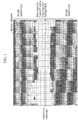
- FIG. 1 is a schematic diagram showing regions of a picture group captured by a camera placed in a motor vehicle traveling on a flat road.
- the image of a detection target object such as a pedestrian or an obstacle, is detected in one of the regions, whereas no image is detected in the other regions.
- Blocks defined by the broken lines in the figure are cells, each in a predetermined size including a plurality of pixels, and obtained by dividing the entire region of a picture captured by the camera.
- the cells herein are the synonym of the pixels obtained by down-sampling the picture captured by the camera at a certain magnification. Shown in white is a region of the pixels that have included one or more times in a bounding box including the detection target object.
- Shaded are the regions of the pixels that have never included in a bounding box. It is found from FIG. 1 that the image of the detection target object is located around the vertical center, which is indicated by a one-dot chain line in the figure, in the image region. That is, the shaded regions can be regarded as the regions that include no image of the detection target object or regions that fail to contribute to a result of objection detection. As the preprocessing described above, cropping is performed in view of the locational tendency of the image of the detection target object in an input image. Certain regions (e.g., two regions "to be removed” in the figure) from the top and bottom of the image region are removed.
- the area (e.g., the "processing target area for object detection") remaining as a result of the preprocessing and positioned around the center of the original image region is regarded as the "target of image recognition processing”. This reduces the amount of calculation as compared to the case where the entire image region is regarded as the "target of image recognition processing”.
- the determination on the target region for image recognition processing based on the idea described above has however the following problem.
- the region of the picture that may include the image of a detection target object changes due to, for example, a bumpy path or a change in the orientation of the moving object.
- the image of the detection target object captured outside the region is then excluded from the target region for image recognition processing.
- the present inventors After repetitive studies for addressing the problem, the present inventors have thought of the following information processing device, program, and information processing method capable of changing a target region for image recognition processing (or a region to be excluded from the image recognition processing in preprocessing) in accordance with a change in the region that may include the image of a detection target object.
- the information processing device a processor.
- the processor obtains at least one of first sensor data output from a first sensor and used to determine an ambient environment of a device in which a third sensor is placed, and second sensor data output from a second sensor and used to determine an orientation of the device; determines a tilt of a plane in a sensing direction of the third sensor with respect to the orientation based on the at least one of the first sensor data and the second sensor data obtained; determines, in accordance with the tilt, a processing target area of third sensor data output from the third sensor and used for object detection processing in the sensing direction; and executes the object detection processing using the processing target area determined, of the third sensor data.
- the device is a motor vehicle, which is a moving object, as in the case described above.
- a flat road surface extends within the field of view in front of the traveling path from the current position of the motor vehicle.
- a camera which is a third sensor, is placed to capture the image of a detection target object, which is present in front of the path, within a region around the vertical center of a picture.
- the plane (hereinafter referred to as a "orientation reference plane" of the motor vehicle) parallel to the longitudinal direction and the transverse direction of the motor vehicle in the straight-ahead orientation and perpendicular to the vertical direction is parallel to the road surface in front of the traveling path.
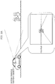
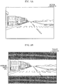
- FIG. 2A is a schematic diagram for illustrating an example where the plane of movement in front of the path of the moving object is, in this manner, not tilted with respect to the orientation reference plane, and a picture captured in this state by the camera placed in the moving object.
- the broken lines extending from the motor vehicle indicate the top and bottom of the shooting range of this camera.
- FIGS. 2B and 2C which will be described later.
- the picture captured in this state by the camera includes the images of people, who are example detection targets, in front of the motor vehicle as shown in the balloon, for example, in the figure.
- the one-dot chain line crossing the image region is the bisector of the height of this image region. The same applies to FIG. 2B and FIG.
- the information processing device determines, in this state, the region of the picture around the vertical center as the "processing target area" to be used for the image recognition processing for object detection.
- the device performs no image recognition processing in the other areas.
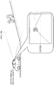
- FIG. 2B is a schematic diagram for illustrating an example where the plane of movement in front of the path of the moving object is, in this manner, tilted with respect to the orientation reference plane, and a picture captured in this state by the camera placed in the moving object.
- the image of the detection target object in front of the motor vehicle is close to the top of the picture, as compared to the state shown in FIG. 2A .
- the information processing device with the configuration described above determines, in this state, an upper part of the picture as the "processing target area" to be used for the image recognition processing for object detection.
- the device performs no image recognition processing in the other areas.
- FIG. 2C is a schematic diagram for illustrating another example where the plane of movement in front of the path of the moving object is tilted with respect to the orientation reference plane, and a picture captured in this state by the camera placed in the moving object.
- the image of the detection target object in front of the motor vehicle is close to the bottom of the picture, as compared to the state shown in FIG. 2A .
- the information processing device determines, in this state, a lower part of the picture as the "processing target area" to be used for the image recognition processing for object detection.
- the device performs no image recognition processing in the other areas.
- the target area for the image recognition processing is changed in accordance with the tilt of the plane of movement in front of the traveling path of the moving object with respect to the orientation reference plane of the moving object.
- the tilt may be hereinafter referred to as a "tilt of the plane of movement in front of the traveling path with respect to the own orientation of the moving object” or simply as a “tilt of the plane of movement with respect to the moving object”.
- the "own orientation” will be described later. That is, the area to be excluded from the target of the image recognition processing is dynamically changed in accordance with the tilt.
- the processor may determine a part of the third sensor data as the processing target area, if the tilt is within a predetermined range, determine a part wider than the part of the third sensor data as the processing target area, if the tilt is out of the predetermined range, and make a processing cycle of the object detection processing longer in a case where the tilt is out of the predetermined range than in a case where the tilt is within the predetermined range.
- the device may be a moving object, and the processor may request the moving object for deceleration, if the tilt is out of the predetermined range.
- the device may be a moving object, and the processor may issue an alert to a user of the moving object, if the tilt is out of the predetermined range.
- the third sensor data may fail to include the area indicating the detection target object.
- the entire third sensor data is used as the target of the object detection processing to reduce the risk of leaving the detection target object undetected.
- the object detection processing of the entire third sensor data may require a longer time than object detection processing of only a part of the third sensor data to provide the accuracy required for safe travel of the moving object.
- the moving object may decelerate for safe travel of the moving object, depending on the time for this object detection processing. An alert indicating that the present situation affects the speed of the object detection processing may be issued to give the user of the moving object an opportunity of considering decelerating the moving object or changing the path.
- the size of the processing target area may be changed in accordance with a factor influencing a reliability of the object detection processing.
- the reliability of the result of the object detection processing may deteriorate.
- the third sensor data is the image data
- the device is a moving object traveling at a relatively high speed or the orientation of the device varies relatively frequently.
- the position of the image of the target to be detected in the picture is likely to change as compared to the other cases.
- the smaller the area of the third sensor data used as the target of the object detection processing is the more likely the target to be detected is left undetected, that is, the lower the reliability of the result of the object detection processing is.
- the object detection processing using a larger area of the third sensor data for example, a wider region of a picture reduces reliability degradation.
- the object detection processing may be executed by inputting the processing target area into one or more trained models.
- the one or more trained models may be a plurality of trained models.
- the processor may select one of the plurality of trained models in accordance with the tilt, and input the processing target area into the one selected.
- the detection target object appears on the data may be different.
- a picture captured by, for example, a camera the image of an object is in different shapes between the case where the object appears near the center of the picture and the case where the object appears on the periphery of the picture.
- this different is more significant.
- the configuration described above improves the accuracy of objection detection using an individual model according to such a difference.
- Each of the trained models may be a multilayer neural network.
- the processor may obtain a distance from the device to a starting point of the tilt; and determine the processing target area for a layer of the trained model according to the distance.
- This configuration allows more accurate detection of detection target objects that may be present at different distances from the device on the plane extending in the sensing direction of the third sensor and inclined with respect to the orientation of the device.
- the processor may determine the processing target area by shifting the processing target area in accordance with the tilt.
- a program is in an information processing device including a processor.
- the program is executed by the processor to cause the processor to obtain at least one of first sensor data output from a first sensor and used to determine an ambient environment of a device in which a third sensor is placed, and second sensor data output from a second sensor and used to determine an orientation of the device, determine a tilt of a plane in a sensing direction of the third sensor with respect to the orientation based on the at least one of the first sensor data and the second sensor data obtained, determine a processing target area of third sensor data output from the third sensor and used for object detection processing in the sensing direction in accordance with the tilt, and execute the object detection processing using the processing target area determined, of the third sensor data.
- An information processing method uses a processor.
- the method includes: obtaining at least one of first sensor data output from a first sensor and used to determine an ambient environment of a device in which a third sensor is placed, and second sensor data output from a second sensor and used to determine an orientation of the device; determining a tilt of a plane in a sensing direction of the third sensor with respect to the orientation based on the at least one of the first sensor data and the second sensor data obtained; determining a processing target area of third sensor data output from the third sensor and used for object detection processing in the sensing direction in accordance with the tilt; and executing the object detection processing using the processing target area determined, of the third sensor data.
- CD-ROM compact disc read-only memory
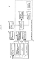
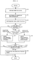
- FIG. 3 is a block diagram showing an example configuration of an information processing device according to an embodiment.
- Information processing device 10 according to this embodiment is a constituent element of object detection system 1 included in a moving object such as a motor vehicle.
- the device receives, as an input, sensor data to be used for object detection.
- the device determines the tilt of a plane of movement in front of the traveling path of the moving object with respect to the moving object based on the sensor data.
- the device executes then the object detection using an area of the sensor data determined in accordance with this tilt.
- information processing device 10 functioning in this manner includes ambient environment determiner 11, own orientation determiner 12, region changer 13, object detection processor 14, processing cycle changer 15, and speed change notifier 16.
- Information processing device 10 is a microcontroller including a processor and a memory, for example. These are functional constituent elements achieved by the processor executing one or more programs stored in the memory. The constituent elements will be described later.
- This microcontroller is, for example, as a component of an electronic control unit (ECU) constituting an in-vehicle network system, mounted in a motor vehicle which is a moving object.
- ECU electronice control unit
- the information processing device according to the present disclosure is useful in various moving objects. This embodiment will now be described using as a main example, information processing device 10 as a microcontroller for an ECU mounted in a motor vehicle.
- Information processing device 10 receives sensor data output from ambient environment sensor 20, such as a sonar sensor or an image sensor of an in-vehicle camera, light detection and ranging or laser imaging detection and ranging (LiDAR) 30 and tilt sensor 40 such as a gyro sensor.
- Position/orientation information from position/orientation obtainer 50 which obtains information on the current position or orientation of the motor vehicle, and map information 60 contained in an in-vehicle car navigation system (not shown) may also be available for information processing device 10.
- information on the current speed of the motor vehicle or ambient brightness (illuminance) around the motor vehicle i.e., speed/illuminance 70 in the figure), for example, may also be input.
- the processing of these data and information will be described below in the explanation of the constituent elements of information processing device 10 and the procedure of the processing of information processing device 10.
- Ambient environment determiner 11 determines the ambient environment of the motor vehicle using the sensor data output from ambient environment sensor 20 or LiDAR 30.
- the ambient environment here is represented by data on the shape of the road surface in front of the path of the motor vehicle, that is, the road surface on which the vehicle travels, or the direction and degree of the tilt of the road surface.
- the road surface in front of the path, which is to be determined as an ambient environment is an example of the plane of movement in this embodiment. What ambient environment determiner 11 may use for the determination on the ambient environment is not limited to these types of sensor data.
- the information on the current position of the motor vehicle supplied from position/orientation obtainer 50 and information on the landscape or the shape of the road included in map information 60 may be used.
- map information 60 the landscape or the shape of the road may be represented by information on the height or by information on more specific three-dimensional shape, if map information 60 is three-dimensional map information. If the position of the motor vehicle is known, the information on the shape of the road surface in front of the path of this motor vehicle in that position is available together with such map information 60.
- Position/orientation obtainer 50 is a functional constituent element achieved by a processor executing one or more programs in information processing device 10 or in another information processing device including the processor and a memory and communicatively connected to information processing device 10. Position/orientation obtainer 50 functions to obtain the position and/or orientation of the motor vehicle using the information output from LiDAR 30 or a receiver of a positioning system such as a global positioning system (GPS, not shown), map information 60, or a combination of these types of information.
- GPS global positioning system
- Own orientation determiner 12 determines the own orientation using the sensor data output from tilt sensor 40 or LiDAR 30.
- Tilt sensor 40 may be included in a motor vehicle, for example, in a car navigation system or a camera (hereinafter referred to as an "in-vehicle camera") placed in a motor vehicle.
- the own orientation here is the orientation of the motor vehicle or the orientation of the in-vehicle camera or a kind of an in-vehicle sensor (a third sensor which will be described later) corresponding to the in-vehicle camera.
- the relative relation between the orientations of the in-vehicle camera and the motor vehicle are available when placing the in-vehicle camera into the motor vehicle. If one of the orientations is known using sensor data, the other orientation can be calculated.
- the own orientation can by represented by the direction and degree of the tilt of a fixed imaginary line or imaginary plane definable relative to the body of the motor vehicle, for example, the orientation reference plane described above, with respect to the vertical line.
- the own orientation may be represented by the direction and degree of the tilt of a fixed imaginary line or imaginary plane definable relative to the in-vehicle camera, for example, the line parallel to the optical axis or the plane parallel to the light receiving surface of the image sensor, with respect to the vertical line.
- what own orientation determiner 12 uses for the determination on the own orientation is not limited to these types of sensor data.
- the information on the current position of the motor vehicle supplied from position/orientation obtainer 50 and the information indicating landscape or the shape of the road included in map information 60 may be used.
- the expression of the "position of the motor vehicle (or the moving object)" in the present disclosure indicates a reference position freely set within a space occupied by the moving object.
- this reference position may be the position of the in-vehicle camera or the third sensor which will be described later.
- Region changer 13 determines the tilt of the plane of movement with respect to the own orientation based on the ambient environment, which a result of determination by ambient environment determiner 11, and the own orientation of the moving object, which is a result of determination by own orientation determiner 12.
- the region changer determines, out of the sensor data input from the in-vehicle camera, that is, the image data in this example, the target area (hereinafter simply referred to as a "processing target area") for image recognition processing performed by object detection processor 14 in accordance with the determined tilt.
- Region changer 13 determines the processing target area according to this tilt, which is the determination result, regardless of whether the own orientation is the orientation of the motor vehicle or the orientation of the in-vehicle camera.
- a program achieving region changer 13 defines the direction in which the processing target area moves in accordance with the direction of the tilt which is the determination result.
- the processing target area may be determined in accordance with the direction of the determined tilt.
- a memory included in information processing device 10 may store a table representing the correlation between the direction and degree of the tilt, which is the determination result, and the coordinate indicating the processing target area of the image region indicated by the image data.
- Region changer 13, which has determined the tilt may obtain the associated coordinate with reference to this table to determine the processing target area.
- the image data cropped as described above by region changer 13 to retain this processing target area may be input from region changer 13 to object detection processor 14.
- uncropped image data and the information, such as the coordinate, indicating the range of the processing target area may be input from region changer 13 to object detection processor 14.
- Object detection processor 14 may crop the data, or image recognition processing may be simply executed for the range of the processing target area indicated by this information. If there is a change in the processing target area, the information, such as the coordinate, indicating a new processing target area may be input from region changer 13 to object detection processor 14.
- information e.g., the direction or the amount of movement
- for shifting the processing target area may be input.
- Region changer 13 may further determine the size of the processing target area.
- the entire region of the image data may be determined as the size of the processing target area, which is equivalent to the determination not to perform cropping.
- the size of the processing target area may be determined in accordance with, for example, the size of the tilt determined as described above. Alternatively, the size may be determined in accordance with the speed of the moving object, the brightness around the moving object or in front of the path, or a change or difference in these factors. These types of information may be a cause that may affect the reliability of object detection. As a specific example, the brightness significantly differs between inside and outside a multistory parking space, particularly, in the daytime on a sunny day, for example.
- a detection target object present outside the exit may not appear recognizably in image recognition processing.
- object detection processor 14 which will be described below, performs image recognition processing at a reliability required for safe travel of the moving object. More specifically, region changer 13 increases the processing target area if the current size of the processing target area fails to exhibit required reliability.
- the speed of the moving object may be obtained from a speed measurement means according to the type of the moving object, for example, in the example of a motor vehicle, from an ECU that calculates the speed of the vehicle based on the rotational speed of the axle measured by a sensor.
- a speed to be used may be calculated based on the position information obtained by a positioning system included in the moving object or the optical flow estimated from a picture captured by a camera.
- the brightness may be obtained based on the data on the picture captured by a camera placed in the moving object or the sensor data output from a brightness sensor included extra in the moving object.
- the cause for reliability degradation of the image recognition processing is not limited to what has been described above. Other examples may include the conditions such as the shape or the harness of the path or the shake or vibration of the moving object caused by wind.
- region changer 13 may lengthen the cycle of the image recognition processing performed by object detection processor 14 as necessary.
- the determined cycle of the image processing is notified to processing cycle changer 15 which will be described later.
- Region changer 13 may determine deceleration of the moving object in addition to or in place of the lengthening of the processing cycle.
- Region changer 13, which has determined this deceleration outputs an instruction on or a request for the deceleration to a control device that controls the speed of the moving object, for example, an ECU that controls a drive mechanism, and/or a brake ECU.
- Object detection processor 14 executes image detection or image recognition processing such as segmentation of the processing target area of the image data determined by region changer 13.
- object detection processor 14 contains a trained model trained for image recognition. This image recognition processing is executed by inputting the processing target area described above of the image data to this trained model.
- the result of the image recognition processing output from object detection processor 14 is utilized by, for example, a driver assistance system or an autonomous driving system in a motor vehicle, for determination on the drive control or notification to a user.
- Processing cycle changer 15 receives the notification from region changer 13 described above, and changes the cycle of the image recognition processing performed by object detection processor 14 in accordance with this notification. The execution of this change is notified from processing cycle changer 15 to speed change notifier 16 which will be described below.
- Speed change notifier 16 which have received this notification from processing cycle changer 15, presents the information on this change to the user of the motor vehicle.
- This information is presented as an alert notifying, for example, a change in the processing cycle and its influence.
- the information may prompt the user for an action such as an operation.
- the information may be supplied in the form of a display on an in-vehicle display device such as a monitor or an instrument panel, or an alarm or a voice through a speaker.
- the image sensor of the in-vehicle camera may function as ambient environment sensor 20 that supplies the sensor data to ambient environment determiner 11.
- the sensor data may be used for the determination on the own orientation by own orientation determiner 12 or may be data to be subjected to image recognition.
- the data output from the LiDAR may be, as described above, the sensor data on the ambient environment and may be the data used for determination on the orientation of the moving object.
- the data may be, as point cloud data, used to detect an object in front of the travel path in addition to or in place of the image data described above.
- a first sensor according to the present disclosure is a sensor that outputs sensor data used to determine the ambient environment.
- a second sensor according to the present disclosure is a sensor that outputs sensor data used to determine the own orientation.
- the third sensor according to the present disclosure is a sensor that outputs sensor data subjected to the processing of detecting an object in front of the moving object in the direction of travel.
- the output sensor data may be used alone or in combination with the other information such as the position information and the map information.
- FIG. 4 is a flow chart showing an example procedure of processing for determination on the processing target area of data, which is the target of the image recognition processing executed by information processing device 10.
- information processing device 10 obtains sensor data from the first sensor, the second sensor, and the third sensor.
- the sensor data obtained from the first, second, and third sensors will be referred to as “first sensor data”, “second sensor data”, and “third sensor data”, respectively.
- the device may obtain map information 60 or information from position/orientation obtainer 50.
- information processing device 10 also obtains the information on the speed of the motor vehicle or the brightness around the motor vehicle.
- ambient environment determiner 11 determines the ambient environment of the motor vehicle, that is, the shape of the plane of movement, for example, in front of the path of the motor vehicle, based on the first sensor data.
- own orientation determiner 12 determines the own orientation based on the second sensor data.
- region changer 13 determines whether or not the plane of movement in front of the path of the motor vehicle is tilted with respect to the own orientation based on the ambient environment and the own orientation. If the plane is not tilted (i.e., No in S43), the procedure of determining the processing target area ends without changing the processing target area of the third sensor data. That is, if the third sensor data is image data, object detection processor 14 executes image recognition processing on the processing target area of this image data, which has been preset for the state where the plane of movement in front of the path of the motor vehicle is not tilted with respect to the own orientation. Assume that this preset processing target area is located around the vertical center of the image in this example. FIG.
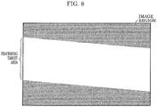
- FIG. 5A is a schematic diagram showing an example picture indicated by the third sensor data input from the in-vehicle camera to information processing device 10.
- FIG. 5B is a schematic diagram showing an example preset target area for image recognition processing, out of the entire region of the picture shown in FIG. 5A .
- the rectangle regions with halftone dots along the top and bottom are the regions to be removed by, for example, cropping processing.
- the region without halftone dots and located around the vertical center in the uncropped picture is the target of the image recognition processing performed by object detection processor 14. If the plane is tilted (Yes in S43), the processing proceeds to step S44.
- region changer 13 obtains the direction of the tilt determined in step S43.
- the front end of the vehicle body is located above the current position, when the motor vehicle moves forward onto the plane of movement which has been determined in step S43 to be tilted.
- the direction at this time is referred to as a "positive direction".
- the positive direction includes the cases: where the path changes from a horizontal plane or a downhill to an uphill in front; where the path changes from a downhill to an uphill in front; where the path changes from a downhill to a horizontal plane in front; where an uphill becomes steeper in front; and where a downhill becomes more gentle in front.
- the negative direction includes the cases: where the path changes from an uphill to a horizontal plane or a downhill in front; where the path changes from a horizontal plane to a downhill in front; where a downhill becomes steeper in front; and where the an uphill becomes gentler in front. That is, the plane is tilted in the positive direction in the example shown in FIG. 2B , and in the negative direction in the example shown in FIG. 2C .
- the processing proceeds to step S45.
- the negative direction the processing proceeds to step S46.
- region changer 13 shifts the target area for the image recognition processing upward. The processing proceeds to step S47.
- region changer 13 shifts the target area for the image recognition processing downward. The processing proceeds to step S47.
- region changer 13 determines whether or not there is a cause of reliability degradation of the image recognition processing.
- region changer 13 further determines whether or not the degree of the tilt determined in step S43 is within a predetermined range. If the degree is within the predetermined range (i.e., No in S47), the procedure of determining the processing target area ends. If the degree of the tilt is out of the predetermined range (Yes in S47), the processing proceeds to step S48.
- region changer 13 may determine whether or not the speed of the motor vehicle obtained by information processing device 10 in step S40 is within a predetermined range. If the speed of the vehicle is within the predetermined range (No in S47), the procedure of determining the processing target area ends. If the speed of the vehicle is out of the predetermined range (Yes in S47), the processing proceeds to step S48.
- region changer 13 may determine whether or not the brightness around the motor vehicle obtained by information processing device 10 in step S40 is lower than or equal to a predetermined illuminance. If the brightness is higher than the predetermined illuminance (No in S47), the procedure of determining the processing target area ends. If the brightness is lower than or equal to the predetermined illuminance (Yes in S47), the processing proceeds to step S48.
- region changer 13 increases the target area for the image recognition processing.
- this processing with information processing device 10 may include a step of determining the amount of shift (or position) of the processing target area according to the degree of the tilt, if the answer is Yes in step S43.
- the processing may include a step of determining the magnification of the processing target area in accordance with the degree of the tilt, the speed of the vehicle, or the illuminance, if the answer is Yes in step S47.
- the processing may include the following steps, if the answer is Yes in step S47.
- processing cycle changer 15 may lengthen the cycle of the image recognition processing by object detection processor 14.
- speed change notifier 16 may provide the user with information on a change in the cycle of this image recognition processing.
- the determination on whether or not there is a cause for reliability degradation i.e., S47
- the processing target area may be increased in at least one of the upward and downward directions of the picture with the central position of the processing target area in the picture unchanged.
- FIG. 6A is a schematic diagram showing an example picture indicated by the third sensor data input from the in-vehicle camera to information processing device 10, if the tilt is in a positive direction.
- FIG. 6B is a schematic diagram showing an example processing target area shifted upward in step S45 in the entire region of the picture shown in FIG. 6A .
- FIG. 7A is a schematic diagram showing an example picture indicated by the third sensor data input from the in-vehicle camera to information processing device 10, if the tilt is in a negative direction.
- FIG. 6A is a schematic diagram showing an example picture indicated by the third sensor data input from the in-vehicle camera to information processing device 10, if the tilt is in a negative direction.
- FIG. 7B is a schematic diagram showing an example processing target area shifted downward in step S46 in the entire region of the picture shown in FIG. 7A .
- the example of the motor vehicle it is not realistic that the presence/absence of the tilt or the direction of the tilt differs in a single place.
- the example pictures in FIGS. 6A, 6B , 7A and 7B show the scene of the same place as in the example pictures in FIGS. 5A and 5B .
- the processing target area includes the scene at a certain distance in front of the path of the motor vehicle, and that an image of an object may be present on and around the path in the scene at a distance to be detected for determination on the details of the control for driver assistance or autonomous driving.
- This scene appears in almost the same manner in the processing target areas shifted in accordance with the tilt in FIGS. 6B and 7B .
- a result of object detection can be provided which is suitably used for determination on the details of the control for driver assistance or autonomous driving.
- the processing target area in the unchanged position includes a closer view than the processing target area in a changed position, and lacks a farther view than the processing target area in the changed position.
- the processing target area in the unchanged position includes a larger amount of sky, in which the detection target object cannot be present, above buildings. The area lacks a part of the area, which is included in the processing target area of FIG. 5B and in which a detection target object can be present on and around the path of the motor vehicle. Even if these unchanged processing target areas are subjected to image recognition processing, a result of object detection cannot be provided which is suitably used for the determination on the details of the control for driver assistance or autonomous driving.
- information processing device 10 excludes a part of the target area for the image recognition processing within the region of the picture captured by the in-vehicle camera to reduce the amount of calculation.
- information processing device 10 changes the position of this processing target area in the image region in accordance with the tilt of the plane of movement in front of the path of the moving object with respect to the own orientation.
- the object detection utilizing the result of the determination on the details of the control for driver assistance or autonomous driving can be executed within a suitable range in the direction of travel.
- the information processing device, the program, and the information processing method according to one or more aspect the present disclosure are not limited to the embodiment described above.
- the present disclosure includes other embodiments, such as those obtained by variously modifying the embodiment as conceived by those skilled in the art without departing from the scope and spirit of the present disclosure. Example variations and supplemental information for explaining the embodiment will be described.
- the system LSI circuit has been named here, but may be replaced with an "integrated circuit (IC)", “large-scale integrated (LSI) circuit", a “super-large-scale integrated (super LSI) circuit”, or an “ultra-large-scale integrated (ultra LSI) circuit", depending on the degree of integration.
- the circuit integration is not limited to the LSI and may be implemented by a dedicated circuit or a general-purpose processor.
- a field-programmable gate array (FPGA) programmable after manufacturing the LSI system, or a reconfigurable processor capable of reconfiguring connection or setting of circuit cells inside the LSI may be used.
- FPGA field-programmable gate array
- Such a system LSI circuit may be incorporated into various in-vehicle systems such as a digital camera, a mobile information terminal, such as a smartphone, equipped with a camera, a back-monitor system, or an advanced driver-assistance system with an object detection function.
- the technique according to the present disclosure is widely useful for information processing for image recognition using sensor data.
- the technique is used for, for example, object detection around a moving object traveling through driver assistance or autonomous moving and in the direction of travel.
Landscapes
- Engineering & Computer Science (AREA)
- Theoretical Computer Science (AREA)
- Physics & Mathematics (AREA)
- General Physics & Mathematics (AREA)
- Evolutionary Computation (AREA)
- Artificial Intelligence (AREA)
- Data Mining & Analysis (AREA)
- Computer Vision & Pattern Recognition (AREA)
- General Health & Medical Sciences (AREA)
- Computing Systems (AREA)
- Software Systems (AREA)
- General Engineering & Computer Science (AREA)
- Life Sciences & Earth Sciences (AREA)
- Health & Medical Sciences (AREA)
- Biomedical Technology (AREA)
- Multimedia (AREA)
- Computational Linguistics (AREA)
- Biophysics (AREA)
- Molecular Biology (AREA)
- Mathematical Physics (AREA)
- Bioinformatics & Computational Biology (AREA)
- Bioinformatics & Cheminformatics (AREA)
- Databases & Information Systems (AREA)
- Medical Informatics (AREA)
- Evolutionary Biology (AREA)
- Traffic Control Systems (AREA)
- Image Analysis (AREA)
- Regulating Braking Force (AREA)
Applications Claiming Priority (3)
| Application Number | Priority Date | Filing Date | Title |
|---|---|---|---|
| US201862747278P | 2018-10-18 | 2018-10-18 | |
| JP2019091583A JP7326018B2 (ja) | 2018-10-18 | 2019-05-14 | 情報処理装置、情報処理方法及びプログラム |
| PCT/JP2019/030794 WO2020079927A1 (ja) | 2018-10-18 | 2019-08-06 | 情報処理装置、プログラム及び情報処理方法 |
Publications (2)
| Publication Number | Publication Date |
|---|---|
| EP3869451A1 true EP3869451A1 (de) | 2021-08-25 |
| EP3869451A4 EP3869451A4 (de) | 2021-12-08 |
Family
ID=70388324
Family Applications (1)
| Application Number | Title | Priority Date | Filing Date |
|---|---|---|---|
| EP19873201.8A Pending EP3869451A4 (de) | 2018-10-18 | 2019-08-06 | Informationsverarbeitungsvorrichtung, programm und informationsverarbeitungsverfahren |
Country Status (3)
| Country | Link |
|---|---|
| EP (1) | EP3869451A4 (de) |
| JP (1) | JP7326018B2 (de) |
| CN (1) | CN111417959B (de) |
Cited By (1)
| Publication number | Priority date | Publication date | Assignee | Title |
|---|---|---|---|---|
| CN116524465A (zh) * | 2023-03-30 | 2023-08-01 | 阿波罗智联(北京)科技有限公司 | 遗撒物识别方法、装置、电子设备、存储介质及产品 |
Families Citing this family (3)
| Publication number | Priority date | Publication date | Assignee | Title |
|---|---|---|---|---|
| WO2022074700A1 (ja) * | 2020-10-05 | 2022-04-14 | 日本電気株式会社 | 情報処理装置、情報処理システム、情報処理方法 |
| JP7387678B2 (ja) * | 2021-06-22 | 2023-11-28 | 株式会社クボタ | 農業機械 |
| CN116620235B (zh) * | 2023-06-21 | 2025-02-14 | 岚图汽车科技有限公司 | Aeb系统控制方法、装置、设备及可读存储介质 |
Family Cites Families (14)
| Publication number | Priority date | Publication date | Assignee | Title |
|---|---|---|---|---|
| JP2010162975A (ja) * | 2009-01-14 | 2010-07-29 | Fujitsu Ten Ltd | 車両制御システム |
| US8630806B1 (en) * | 2011-10-20 | 2014-01-14 | Google Inc. | Image processing for vehicle control |
| US9145140B2 (en) * | 2012-03-26 | 2015-09-29 | Google Inc. | Robust method for detecting traffic signals and their associated states |
| JP6119198B2 (ja) * | 2012-11-07 | 2017-04-26 | 株式会社デンソー | 車載レーダ装置 |
| KR101641490B1 (ko) * | 2014-12-10 | 2016-07-21 | 엘지전자 주식회사 | 차량 운전 보조 장치 및 이를 구비한 차량 |
| JP6488749B2 (ja) * | 2015-02-13 | 2019-03-27 | 株式会社デンソー | カメラ校正装置 |
| JP6657925B2 (ja) * | 2015-06-04 | 2020-03-04 | ソニー株式会社 | 車載カメラ・システム並びに画像処理装置 |
| DE102015224192B4 (de) * | 2015-12-03 | 2021-03-18 | Robert Bosch Gmbh | Erkennen einer Freifläche |
| CN107226091B (zh) * | 2016-03-24 | 2021-11-26 | 松下电器(美国)知识产权公司 | 物体检测装置、物体检测方法以及记录介质 |
| TWI611961B (zh) * | 2016-06-01 | 2018-01-21 | 緯創資通股份有限公司 | 車道線影像分析方法、影像分析裝置及其電腦可讀取式媒體 |
| JP6759899B2 (ja) * | 2016-09-08 | 2020-09-23 | アイシン精機株式会社 | 車両用画像処理装置 |
| KR101786580B1 (ko) * | 2016-09-29 | 2017-10-19 | 현대오트론 주식회사 | 후방 카메라 영상의 보정 장치 및 방법 |
| KR102697448B1 (ko) * | 2016-11-30 | 2024-08-21 | 삼성전자주식회사 | 자율 주행 경로 생성 방법 및 그 장치 |
| EP3574447B1 (de) * | 2017-01-27 | 2023-10-11 | Gentex Corporation | Bildkompensation für motorradschräglage |
-
2019
- 2019-05-14 JP JP2019091583A patent/JP7326018B2/ja active Active
- 2019-08-06 EP EP19873201.8A patent/EP3869451A4/de active Pending
- 2019-08-06 CN CN201980005343.8A patent/CN111417959B/zh active Active
Cited By (1)
| Publication number | Priority date | Publication date | Assignee | Title |
|---|---|---|---|---|
| CN116524465A (zh) * | 2023-03-30 | 2023-08-01 | 阿波罗智联(北京)科技有限公司 | 遗撒物识别方法、装置、电子设备、存储介质及产品 |
Also Published As
| Publication number | Publication date |
|---|---|
| EP3869451A4 (de) | 2021-12-08 |
| CN111417959A (zh) | 2020-07-14 |
| CN111417959B (zh) | 2024-09-17 |
| JP7326018B2 (ja) | 2023-08-15 |
| JP2020064603A (ja) | 2020-04-23 |
Similar Documents
| Publication | Publication Date | Title |
|---|---|---|
| US11769052B2 (en) | Distance estimation to objects and free-space boundaries in autonomous machine applications | |
| US12131556B2 (en) | Object fence generation for lane assignment in autonomous machine applications | |
| US20230205219A1 (en) | Path detection for autonomous machines using deep neural networks | |
| CN113454636B (zh) | 自主机器应用中障碍物检测的距离 | |
| US12374040B2 (en) | Environment reconstruction and path planning for autonomous systems and applications | |
| JP6878493B2 (ja) | 自動運転車両(adv)に用いるピッチ角の補正方法 | |
| US12346119B2 (en) | Obstacle to path assignment and performance of control operations based on assignment for autonomous systems and applications | |
| CN110494863B (zh) | 确定自主车辆的可驾驶自由空间 | |
| US11341670B2 (en) | Information processing device, information processing method, and recording medium | |
| EP3400556B1 (de) | Systeme und verfahren zur schätzung zukünftiger pfade | |
| CN113906271A (zh) | 用于自主机器应用的使用地图信息增强的地面实况数据的神经网络训练 | |
| CN112904370A (zh) | 用于激光雷达感知的多视图深度神经网络 | |
| WO2019182974A2 (en) | Stereo depth estimation using deep neural networks | |
| EP3869451A1 (de) | Informationsverarbeitungsvorrichtung, programm und informationsverarbeitungsverfahren | |
| JP2019189213A (ja) | 自動運転車における車線後処理 | |
| CN112970029A (zh) | 用于自主机器应用中传感器视盲检测的深度神经网络处理 | |
| US20240410705A1 (en) | Path detection using machine learning models for autonomous systems and applications | |
| US12116008B2 (en) | Attentional sampling for long range detection in autonomous vehicles | |
| CN119590408B (zh) | 基于双目摄像头的代客泊车方法、装置、设备及存储介质 | |
| US12470836B2 (en) | Systems and methods for downsampling images | |
| KR20250033522A (ko) | 이미지에 기반하여 차량의 사각지대를 모니터링하는 방법 및 장치 | |
| CN121120914A (zh) | 用于自主和半自主系统及应用的使用局部表面拟合的地表面估计 | |
| CN121120913A (zh) | 用于自主和半自主系统及应用的使用立体成像的地表面估计 |
Legal Events
| Date | Code | Title | Description |
|---|---|---|---|
| STAA | Information on the status of an ep patent application or granted ep patent |
Free format text: STATUS: THE INTERNATIONAL PUBLICATION HAS BEEN MADE |
|
| PUAI | Public reference made under article 153(3) epc to a published international application that has entered the european phase |
Free format text: ORIGINAL CODE: 0009012 |
|
| STAA | Information on the status of an ep patent application or granted ep patent |
Free format text: STATUS: REQUEST FOR EXAMINATION WAS MADE |
|
| 17P | Request for examination filed |
Effective date: 20210412 |
|
| AK | Designated contracting states |
Kind code of ref document: A1 Designated state(s): AL AT BE BG CH CY CZ DE DK EE ES FI FR GB GR HR HU IE IS IT LI LT LU LV MC MK MT NL NO PL PT RO RS SE SI SK SM TR |
|
| REG | Reference to a national code |
Ref country code: DE Ref legal event code: R079 Free format text: PREVIOUS MAIN CLASS: G06T0007000000 Ipc: G06K0009000000 |
|
| A4 | Supplementary search report drawn up and despatched |
Effective date: 20211110 |
|
| RIC1 | Information provided on ipc code assigned before grant |
Ipc: G06K 9/32 20060101ALI20211104BHEP Ipc: G06T 7/70 20170101ALI20211104BHEP Ipc: G06N 3/08 20060101ALI20211104BHEP Ipc: G06K 9/62 20060101ALI20211104BHEP Ipc: G06K 9/00 20060101AFI20211104BHEP |
|
| DAV | Request for validation of the european patent (deleted) | ||
| DAX | Request for extension of the european patent (deleted) | ||
| STAA | Information on the status of an ep patent application or granted ep patent |
Free format text: STATUS: EXAMINATION IS IN PROGRESS |
|
| 17Q | First examination report despatched |
Effective date: 20231207 |