EP3869429A1 - Determination device and determination system - Google Patents
Determination device and determination system Download PDFInfo
- Publication number
- EP3869429A1 EP3869429A1 EP21151142.3A EP21151142A EP3869429A1 EP 3869429 A1 EP3869429 A1 EP 3869429A1 EP 21151142 A EP21151142 A EP 21151142A EP 3869429 A1 EP3869429 A1 EP 3869429A1
- Authority
- EP
- European Patent Office
- Prior art keywords
- component
- operation procedure
- procedure manual
- image
- determination device
- Prior art date
- Legal status (The legal status is an assumption and is not a legal conclusion. Google has not performed a legal analysis and makes no representation as to the accuracy of the status listed.)
- Granted
Links
Images


Classifications
-
- G—PHYSICS
- G06—COMPUTING OR CALCULATING; COUNTING
- G06Q—INFORMATION AND COMMUNICATION TECHNOLOGY [ICT] SPECIALLY ADAPTED FOR ADMINISTRATIVE, COMMERCIAL, FINANCIAL, MANAGERIAL OR SUPERVISORY PURPOSES; SYSTEMS OR METHODS SPECIALLY ADAPTED FOR ADMINISTRATIVE, COMMERCIAL, FINANCIAL, MANAGERIAL OR SUPERVISORY PURPOSES, NOT OTHERWISE PROVIDED FOR
- G06Q10/00—Administration; Management
- G06Q10/20—Administration of product repair or maintenance
-
- G—PHYSICS
- G06—COMPUTING OR CALCULATING; COUNTING
- G06F—ELECTRIC DIGITAL DATA PROCESSING
- G06F18/00—Pattern recognition
- G06F18/20—Analysing
- G06F18/22—Matching criteria, e.g. proximity measures
-
- G—PHYSICS
- G06—COMPUTING OR CALCULATING; COUNTING
- G06F—ELECTRIC DIGITAL DATA PROCESSING
- G06F3/00—Input arrangements for transferring data to be processed into a form capable of being handled by the computer; Output arrangements for transferring data from processing unit to output unit, e.g. interface arrangements
- G06F3/14—Digital output to display device ; Cooperation and interconnection of the display device with other functional units
-
- G—PHYSICS
- G06—COMPUTING OR CALCULATING; COUNTING
- G06T—IMAGE DATA PROCESSING OR GENERATION, IN GENERAL
- G06T7/00—Image analysis
- G06T7/0002—Inspection of images, e.g. flaw detection
- G06T7/0004—Industrial image inspection
- G06T7/001—Industrial image inspection using an image reference approach
-
- B—PERFORMING OPERATIONS; TRANSPORTING
- B64—AIRCRAFT; AVIATION; COSMONAUTICS
- B64F—GROUND OR AIRCRAFT-CARRIER-DECK INSTALLATIONS SPECIALLY ADAPTED FOR USE IN CONNECTION WITH AIRCRAFT; DESIGNING, MANUFACTURING, ASSEMBLING, CLEANING, MAINTAINING OR REPAIRING AIRCRAFT, NOT OTHERWISE PROVIDED FOR; HANDLING, TRANSPORTING, TESTING OR INSPECTING AIRCRAFT COMPONENTS, NOT OTHERWISE PROVIDED FOR
- B64F5/00—Designing, manufacturing, assembling, cleaning, maintaining or repairing aircraft, not otherwise provided for; Handling, transporting, testing or inspecting aircraft components, not otherwise provided for
- B64F5/50—Handling or transporting aircraft components
-
- B—PERFORMING OPERATIONS; TRANSPORTING
- B64—AIRCRAFT; AVIATION; COSMONAUTICS
- B64F—GROUND OR AIRCRAFT-CARRIER-DECK INSTALLATIONS SPECIALLY ADAPTED FOR USE IN CONNECTION WITH AIRCRAFT; DESIGNING, MANUFACTURING, ASSEMBLING, CLEANING, MAINTAINING OR REPAIRING AIRCRAFT, NOT OTHERWISE PROVIDED FOR; HANDLING, TRANSPORTING, TESTING OR INSPECTING AIRCRAFT COMPONENTS, NOT OTHERWISE PROVIDED FOR
- B64F5/00—Designing, manufacturing, assembling, cleaning, maintaining or repairing aircraft, not otherwise provided for; Handling, transporting, testing or inspecting aircraft components, not otherwise provided for
- B64F5/60—Testing or inspecting aircraft components or systems
-
- G—PHYSICS
- G06—COMPUTING OR CALCULATING; COUNTING
- G06T—IMAGE DATA PROCESSING OR GENERATION, IN GENERAL
- G06T2207/00—Indexing scheme for image analysis or image enhancement
- G06T2207/30—Subject of image; Context of image processing
- G06T2207/30108—Industrial image inspection
- G06T2207/30164—Workpiece; Machine component
-
- Y—GENERAL TAGGING OF NEW TECHNOLOGICAL DEVELOPMENTS; GENERAL TAGGING OF CROSS-SECTIONAL TECHNOLOGIES SPANNING OVER SEVERAL SECTIONS OF THE IPC; TECHNICAL SUBJECTS COVERED BY FORMER USPC CROSS-REFERENCE ART COLLECTIONS [XRACs] AND DIGESTS
- Y02—TECHNOLOGIES OR APPLICATIONS FOR MITIGATION OR ADAPTATION AGAINST CLIMATE CHANGE
- Y02P—CLIMATE CHANGE MITIGATION TECHNOLOGIES IN THE PRODUCTION OR PROCESSING OF GOODS
- Y02P90/00—Enabling technologies with a potential contribution to greenhouse gas [GHG] emissions mitigation
- Y02P90/30—Computing systems specially adapted for manufacturing
Definitions
- the invention relates to a determination device and a determination system, and specifically relates to a determination device and a determination system configured to determine whether a component and an operation procedure manual match.
- An aspect of the invention provides a determination device.
- the device includes a computer.
- the computer is configured to compare an image of a component that is captured and a correct image that is associated with an operation procedure manual and in which the component is captured.
- the computer is configured to determine whether a component shape in the image of the component and a component shape in the correct image agree. If the two component shapes do not agree, the computer is configured to determine that the component and the operation procedure manual do not match.
- the system includes an input device, an imaging device, a database, and the determination device.
- the input device is configured to input the number of an operation procedure manual.
- the imaging device is configured to capture an image of a component.
- the database is configured to store a correct image that is associated with the operation procedure manual and in which the component is captured.
- the determination device is configured to compare an image of the component captured by the imaging device and the correct image associated with the operation procedure manual of the number input with the input device.
- a mismatch that is, that the component and the component originally corresponding to the operation procedure manual are different
- a mismatch that is, that the component and the component originally corresponding to the operation procedure manual are different
- aircraft components include many components that are very alike and difficult to be distinguished from one another and therefore, a problem of performing numbering without noticing a mismatch occurring between the component and the operation procedure manual (which is erroneous numbering) may be caused.
- the invention has been made in view of the above-described respects and it is desirable to provide a determination device and a determination system that can precisely determine whether a mismatch is occurring between a component and an operation procedure manual.
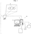
- FIG. 1 is a diagram illustrating a configuration of a determination system 10 according to the present embodiment.
- the determination system 10 includes a determination device 1, an input device 2, an imaging device 3, a database 4, and so on.
- the determination system 10 includes other necessary devices, such as an illumination device and the like.
- the input device 2 is used to input the number of an operation procedure manual A and, in the present embodiment, is a code reader to read and input a two-dimensional code that is specified in the operation procedure manual A and includes information on the number of the operation procedure manual A.
- a keyboard or the like can also be used as the input device 2.
- the imaging device 3 is used to taken an image of a component B and configured to take a still image I in color, which is presented in RGB color space in the present embodiment. Further, the imaging device 3 is configured to transmit the taken image I to the determination device 1 after taking the image I of the component B.
- an image of the component B is taken in a state of being secured with an unillustrated jig and the positional relation between the imaging device 3 and the component B is caused to be the same positional relation as that in a case where a later-described correct image 10 of the component B, which is an image regarded as being correct and obtained by taking the component B correctly manufactured.
- the database 4 may be a storage means installed in the determination device 1. Further, the database 4 need not necessarily be directly coupled to the determination device 1 or the like but, for example, may be coupled via a communication network or be provided on a cloud.
- the operation procedure manuals A and the correct images 10 of the component B corresponding to the operation procedure manuals A are stored in advance while the correct images 10 are associated with the respective operation procedure manuals A.
- the correct image 10 is an image taken through careful inspection (initial article inspection) regarding whether the component B is manufactured in accordance with the operation procedure manual in, for example, initial manufacturing in assembly of an aircraft.
- the correct image 10 is taken with the component B being secured with the unillustrated jig.
- an image I is taken with the imaging device 3 of the determination system 10 according to the present embodiment after the second manufacturing, as described above, the image I is taken with the component B being secured with the jig in the same state of that while the correct image I0 is taken.
- the imaging device 3 is caused to take an image from the same distance and the same direction and under the same magnification relative to the component B and the jig as those in the initial article inspection.
- the positional relation between the imaging device 3 and the component B at the time of taking the image I with the imaging device 3 of the determination system 10 according to the present embodiment is the same positional relation as that at the time of taking the correct image 10 in the initial article inspection.
- the determination device 1 according to the present embodiment is described below.
- the determination device 1 in the present embodiment is constituted by a computer where a central processing unit (CPU), read only memory (ROM), random access memory (RAM), input and output interfaces, and the like, not illustrated, are coupled to a bus
- the determination device 1 may also be constituted by a dedicated device for example.
- the determination device 1 includes a display screen 11 constituted by a liquid crystal display, an organic EL display, or the like.
- the determination device 1 reads the correct image I0 associated with the operation procedure manual A with the number input through the input device 2 out from the database 4 and compares the image I of the component B captured by the imaging device 3 and the correct image 10 associated with the operation procedure manual A of the number input through the input device 2 to determine whether the component shape shown in the image I of the component B captured and the component shape shown in the correct image 10 match. If the two component shapes do not match, the determination device 1 determines that the component B and the operation procedure manual A do not match.
- a user such as a worker, brings the component B manufactured and the operation procedure manual A corresponding to the manufactured component B to the determination system 10 and inputs the number or the like of the operation procedure manual A by causing the code reader, which is the input device 2, to read the two-dimensional code of the operation procedure manual A.
- the user secures the component B with the unillustrated jig disposed further forward than the imaging device 3 and takes an image of the component B with the imaging device 3.
- the determination device 1 Upon the input of the number or the like of the operation procedure manual A, the determination device 1 reads the correct image I0 associated with the operation procedure manual A of the input number out from the database 4.
- the component shape of the component B shown in the image I is identified from the image I of the component B captured by the imaging device 3. Further, the component shape shown in the correct image 10 is identified.
- a shadow S of the component B is made differently even when the distance or orientation of the component B relative to the imaging device 3 is unchanged. Accordingly, if the component shape is identified while the shadow S of the component B is shown in the image, a different component shape can be identified because of the difference in the shape of the shadow S even when the component B is shown in the image in the same state.
- the RGB color space of the image I taken with the imaging device 3 or the correct image 10 can be converted to an HSV color space and the image I or the correct image 10 can be modified on the basis of the hue (H component) and the chroma (S component) that are included in the resultant. Since the modified image I or the correct image 10 does not have lightness (V component), the shadow S that appears as a difference in lightness is deleted from the modified image I or the correct image 10.
- the determination device 1 compares the component shape of the component B shown in the image I of the component B captured (or the modified image I, which is the same hereinafter) and the component shape of the component B shown in the correct image 10 (or the modified correct image I0, which is the same hereinafter) and determines whether the component shapes agree. Since the method of determining whether the component shapes shown in images agree is known, the description thereon is omitted.
- the determination device 1 determines that the respective component shapes shown in the two images I and 10 do not match, the determination device 1 determines that the component B and the operation procedure manual A do not match.
- the determination device 1 determines that the respective component shapes shown in the two images I and 10 do not match.
- the component B0 captured in the correct image I0 is different from the component B brought by the user and therefore, the operation procedure manual A with which the correct image 10 is associated relates to the component B0, not relating to the component B.
- the determination device 1 determines that the component B and the operation procedure manual A brought by the user do not match.
- the determination device 1 compares the image I of the component B captured and the correct image I0 associated with the operation procedure manual A, and if the component shape of the component B shown in the image I of the component B and the component shape shown in the correct image I0 agree, the determination device 1 determines that the component B and the operation procedure manual A brought by the user match.
- the component shape shown in the image I in which the component B brought by the user is captured and the component shape shown in the correct image 10 associated with the operation procedure manual brought by the user are compared and if the two component shapes agree, it is determined that the component B and the operation procedure manual A brought by the user match, whereas if the two component shapes do not agree, it is determined that the component B and the operation procedure manual A brought by the user do not match.
- the determination device 1 can be configured to inform the user that the component B and the operation procedure manual A brought by the user match by causing "OK" or the like to be displayed on the display screen 11 together with the image I of the component B captured by the imaging device 3.
- the informing may use voice or the like.
- Such configurations enable the user to make sure that the brought component B and operation procedure manual A match and transfer the component B and the operation procedure manual A to a subsequent process, such as numbering, without concern.
- the determination device 1 can also be configured to cause various kinds of information and the like to be displayed on the display screen 11 so as to inform the user, and such is performed when appropriate.
- the determination device 1 can be configured to, when the determination device 1 determines that the component B and the operation procedure manual A brought by the user do not match as described above, cause the correct image I0 associated with the operation procedure manual A brought by the user to be displayed on the display screen 11 so as to inform the user of the mismatch.
- the determination device 1 causes "MISMATCH" or the like to be displayed on the display screen 11 as illustrated in FIG. 5 .
- the determination device 1 can be configured to inform the user of a component B0 corresponding to the operation procedure manual A brought by the user by causing "THE COMPONENT CORRESPONDING TO THE OPERATION PROCEDURE MANUAL THAT YOU HAVE IS THE FOLLOWING.” or the like to be displayed and causing the correct image 10 to be displayed largely, for example.
- the user finds the component B0 displayed and places the component B0 in front of the imaging device 3 to take an image thereof, and then causes the determination device 1 to perform determination in a manner similar to that described above and causes the determination device 1 to determine whether the component B0 newly brought and the operation procedure manual A match.
- the determination device 1 determines that the component brought by the user matches the operation procedure manual A brought by the user, the determination device 1 informs the user that the component B0 brought by the user matches the operation procedure manual A by causing "OK” or the like to be displayed as illustrated in FIG. 4 .
- the determination device 1 determines that the component brought by the user does not match the operation procedure manual A brought by the user, the determination device 1 informs the user again that the component B brought by the user and the operation procedure manual A do not match by causing "MISMATCH" to be displayed as illustrated in FIG. 5 again or causing the component B0 (the correct image 10) corresponding to the operation procedure manual A brought by the user to be displayed largely again for example.
- the component B that does not match the operation procedure manual A is in the state of not having any corresponding operation procedure manual A.
- the determination device 1 can be configured to, when the determination device 1 determines that the component B and the operation procedure manual A brought by the user do not match as described above, extract the correct image I0 where the component B concerned is shown from among the correct images 10 stored in the database 4 and cause an operation procedure manual A0 associated with the extracted correct image 10 or information on the operation procedure manual A0 to be displayed on the display screen 11.
- the determination device 1 can be configured to compare the component shape of the component B shown in the image I of the component B captured by the imaging device 3 and the component shape shown in the correct image 10 and extract the correct image 10 with the matching component shape.
- the determination device 1 causes "MISMATCH" or the like to be displayed on the display screen 11 as illustrated in FIG. 6 for example.
- the determination device 1 can be configured to inform the user of the operation procedure manual A corresponding to the component B brought by the user by causing "THE OPERATION PROCEDURE MANUAL CORRESPONDING TO THE COMPONENT THAT YOU HAVE IS THE FOLLOWING.” or the like to be displayed and causing the operation procedure manual A0 associated with the extracted correct image 10 to be displayed largely, for example.
- the determination device 1 may also be configured to cause information on the operation procedure manual A, such as the number, to be displayed instead of or in addition to causing the operation procedure manual A itself to be displayed.
- the user finds the displayed operation procedure manual A and inputs the number or the like of the operation procedure manual A by causing the code reader as the input device 2 to read the two-dimensional code of the operation procedure manual A, and then causes the determination device 1 to perform determination in a manner similar to that described above and causes the determination device 1 to determine whether the component B and the operation procedure manual A newly brought match.
- the determination device 1 determines that the operation procedure manual A brought by the user matches the component B brought by the user
- the determination device 1 informs the user that the operation procedure manual A brought by the user matches the component B by causing "OK” or the like to be displayed as illustrated in FIG. 4 .
- the determination device 1 determines that the operation procedure manual A brought by the user does not match the component B brought by the user, the determination device 1 informs the user again that the component B and the operation procedure manual A brought by the user do not match by causing "MISMATCH" to be displayed as illustrated in FIG. 5 again or causing the operation procedure manual A0 corresponding to the component B concerned to be displayed largely again, for example.
- the determination device 1 and the determination system 10 are configured to precisely determine whether the component B and the operation procedure manual A brought by the user match and if the component B and the operation procedure manual A brought by the user do not match, inform the user of the correct component B0 by causing the correct image 10 associated with the operation procedure manual A brought by the user to be displayed or inform the user by causing the correct operation procedure manual A0 corresponding to the component B brought by the user and information thereon to be displayed.
- the user can find the correct component B0 that matches the operation procedure manual A or can find the correct operation procedure manual A0 that matches the component B, and the component B and the operation procedure manual A can be matched precisely.
- the user can make sure that the component B and the operation procedure manual A match and transfer the component B and the operation procedure manual A to a subsequent process, such as numbering, without concern.
- FIG 5 and FIG 6 each present a case where the image I in which the component B brought by the user is captured is displayed on the display screen 11 of the determination device 1, it is possible for the image I in which the component B brought by the user is captured not to be displayed on the display screen 11.
- the determination device 1 can be configured to perform automatic numbering on the component B using a numbering device when the determination device 1 determines that the component B and the operation procedure manual A brought by the user match, by transferring the component B to the numbering device automatically and transmitting necessary information from the determination device 1 to the numbering device, for example.
- the subsequent process of the determination process by the determination device 1 and the determination system 10 may be other processes than the numbering process for the component B.
- the determination device 1 and the determination system 10 can be used widely to check a match between the component B and the operation procedure manual A and can also be used in finding the operation procedure manual A that matches the component B or the component B that matches the operation procedure manual A.
Landscapes
- Engineering & Computer Science (AREA)
- Theoretical Computer Science (AREA)
- Business, Economics & Management (AREA)
- Physics & Mathematics (AREA)
- General Physics & Mathematics (AREA)
- Human Resources & Organizations (AREA)
- Quality & Reliability (AREA)
- General Engineering & Computer Science (AREA)
- Computer Vision & Pattern Recognition (AREA)
- Operations Research (AREA)
- Economics (AREA)
- General Business, Economics & Management (AREA)
- Strategic Management (AREA)
- Marketing (AREA)
- Entrepreneurship & Innovation (AREA)
- Data Mining & Analysis (AREA)
- Tourism & Hospitality (AREA)
- Human Computer Interaction (AREA)
- Artificial Intelligence (AREA)
- Bioinformatics & Cheminformatics (AREA)
- Bioinformatics & Computational Biology (AREA)
- Evolutionary Biology (AREA)
- Evolutionary Computation (AREA)
- Life Sciences & Earth Sciences (AREA)
- Image Analysis (AREA)
- Management, Administration, Business Operations System, And Electronic Commerce (AREA)
Abstract
Description
- The invention relates to a determination device and a determination system, and specifically relates to a determination device and a determination system configured to determine whether a component and an operation procedure manual match.
- When the product quantities of components are large (that is, when the lots of components are large), for example, the components are often manufactured while being transferred on manufacturing lines. However, for example, when components are produced into multiple models in small lots and the lot of each component is small like the components of an aircraft, many of such components are produced by workers one by one.
- Also for the production sites of such small-lot production of multiple models, various techniques for automatic production management and the like using a computer with a minimum of involvement by manual labor are proposed (see, for example, Japanese Unexamined Patent Application Publications
JP 2014-035 635 A JP 2016-221 671 A JP 6 491 194 B2 - An aspect of the invention provides a determination device. The device includes a computer. The computer is configured to compare an image of a component that is captured and a correct image that is associated with an operation procedure manual and in which the component is captured. The computer is configured to determine whether a component shape in the image of the component and a component shape in the correct image agree. If the two component shapes do not agree, the computer is configured to determine that the component and the operation procedure manual do not match.
- Another aspect of the invention provides a determination system. The system includes an input device, an imaging device, a database, and the determination device. The input device is configured to input the number of an operation procedure manual. The imaging device is configured to capture an image of a component. The database is configured to store a correct image that is associated with the operation procedure manual and in which the component is captured. The determination device is configured to compare an image of the component captured by the imaging device and the correct image associated with the operation procedure manual of the number input with the input device.
- The accompanying drawings are included to provide a further understanding of the invention and are incorporated in and constitute a part of this specification. The drawings illustrate embodiments and, together with the specification, serve to explain the principles of the invention.
- FIG. 1
- is a diagram illustrating a configuration of a determination system according to an embodiment of the invention;
- FIGS. 2A and 2B
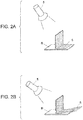
- are diagrams for describing that, how a shadow is made, changes as the height of an illumination device and the illumination direction of the light vary;
- FIG. 3A
- is a diagram illustrating an example of an image in which a component brought by a user is captured, and
- FIG. 3B
- is a diagram illustrating an example of a correct image associated with an operation procedure manual brought by the user;
- FIG. 4
- is a diagram illustrating a display example on a display screen in a case where a determination device determines that the component and the operation procedure manual match;
- FIG. 5
- is a diagram illustrating a display example on the display screen in a case where the determination device determines that the component and the operation procedure manual do not match and a correct image is displayed on the display screen; and
- FIG. 6
- is a diagram illustrating a display example on the display screen in a case where the determination device determines that the component and the operation procedure manual do not match and the operation procedure manual is displayed on the display screen.
- When, for example, numbering is performed on manufactured components if the product quantity of the components is large, the manufactured components undergo the numbering automatically while transferred on a manufacturing line or the like, whereas in a case of small-lot production of multiple models, such numbering is often performed through visual check by workers or the like regarding whether a component and an operation procedure manual, where the manufacturing procedures and the like of the component for identification of the component are described, match.
- However, when a worker or the like transfers a manufactured component with man power to a subsequent process together with an operation procedure manual for example, a mismatch (that is, that the component and the component originally corresponding to the operation procedure manual are different) may occur between the component and the operation procedure manual.
- For example, aircraft components include many components that are very alike and difficult to be distinguished from one another and therefore, a problem of performing numbering without noticing a mismatch occurring between the component and the operation procedure manual (which is erroneous numbering) may be caused.
- The invention has been made in view of the above-described respects and it is desirable to provide a determination device and a determination system that can precisely determine whether a mismatch is occurring between a component and an operation procedure manual.
- In the following, an embodiment of the invention is described in detail with reference to the accompanying drawings. Note that the following description is directed to an illustrative example of the invention and not to be construed as limiting to the invention. Factors including, without limitation, numerical values, shapes, materials, components, positions of the components, and how the components are coupled to each other are illustrative only and not to be construed as limiting to the invention.
- Further, elements in the following embodiment which are not recited in a most-generic independent claim of the invention are optional and may be provided on an as-needed basis. The drawings are schematic and are not intended to be drawn to scale. Throughout the present specification and the drawings, elements having substantially the same function and configuration are denoted with the same numerals to avoid any redundant description.
- Also in the description below, a case where a component of an aircraft is manufactured is taken as an example but the invention is not limited to the case.
-
FIG. 1 is a diagram illustrating a configuration of adetermination system 10 according to the present embodiment. - In the present embodiment, the
determination system 10 includes adetermination device 1, aninput device 2, animaging device 3, adatabase 4, and so on. - In addition, the
determination system 10 includes other necessary devices, such as an illumination device and the like. - The
input device 2 is used to input the number of an operation procedure manual A and, in the present embodiment, is a code reader to read and input a two-dimensional code that is specified in the operation procedure manual A and includes information on the number of the operation procedure manual A. - A keyboard or the like can also be used as the
input device 2. - The
imaging device 3 is used to taken an image of a component B and configured to take a still image I in color, which is presented in RGB color space in the present embodiment. Further, theimaging device 3 is configured to transmit the taken image I to thedetermination device 1 after taking the image I of the component B. - In the present embodiment, an image of the component B is taken in a state of being secured with an unillustrated jig and the positional relation between the
imaging device 3 and the component B is caused to be the same positional relation as that in a case where a later-describedcorrect image 10 of the component B, which is an image regarded as being correct and obtained by taking the component B correctly manufactured. - The
database 4 may be a storage means installed in thedetermination device 1. Further, thedatabase 4 need not necessarily be directly coupled to thedetermination device 1 or the like but, for example, may be coupled via a communication network or be provided on a cloud. - In the
database 4, the operation procedure manuals A and thecorrect images 10 of the component B corresponding to the operation procedure manuals A are stored in advance while thecorrect images 10 are associated with the respective operation procedure manuals A. - The
correct image 10 is an image taken through careful inspection (initial article inspection) regarding whether the component B is manufactured in accordance with the operation procedure manual in, for example, initial manufacturing in assembly of an aircraft. - Further, in that time, the
correct image 10 is taken with the component B being secured with the unillustrated jig. - Also when an image I is taken with the
imaging device 3 of thedetermination system 10 according to the present embodiment after the second manufacturing, as described above, the image I is taken with the component B being secured with the jig in the same state of that while the correct image I0 is taken. - That is, the
imaging device 3 is caused to take an image from the same distance and the same direction and under the same magnification relative to the component B and the jig as those in the initial article inspection. Thus, the positional relation between theimaging device 3 and the component B at the time of taking the image I with theimaging device 3 of thedetermination system 10 according to the present embodiment is the same positional relation as that at the time of taking thecorrect image 10 in the initial article inspection. - The
determination device 1 according to the present embodiment is described below. - Although the
determination device 1 in the present embodiment is constituted by a computer where a central processing unit (CPU), read only memory (ROM), random access memory (RAM), input and output interfaces, and the like, not illustrated, are coupled to a bus, thedetermination device 1 may also be constituted by a dedicated device for example. Further, thedetermination device 1 includes adisplay screen 11 constituted by a liquid crystal display, an organic EL display, or the like. - The
determination device 1 reads the correct image I0 associated with the operation procedure manual A with the number input through theinput device 2 out from thedatabase 4 and compares the image I of the component B captured by theimaging device 3 and thecorrect image 10 associated with the operation procedure manual A of the number input through theinput device 2 to determine whether the component shape shown in the image I of the component B captured and the component shape shown in thecorrect image 10 match. If the two component shapes do not match, thedetermination device 1 determines that the component B and the operation procedure manual A do not match. - The foregoing configuration and further configuration of the
determination device 1 are described below along the sequence of operation. In addition, functions and effects are also described. - A user, such as a worker, brings the component B manufactured and the operation procedure manual A corresponding to the manufactured component B to the
determination system 10 and inputs the number or the like of the operation procedure manual A by causing the code reader, which is theinput device 2, to read the two-dimensional code of the operation procedure manual A. - Further, the user secures the component B with the unillustrated jig disposed further forward than the
imaging device 3 and takes an image of the component B with theimaging device 3. - Upon the input of the number or the like of the operation procedure manual A, the
determination device 1 reads the correct image I0 associated with the operation procedure manual A of the input number out from thedatabase 4. - After that, the component shape of the component B shown in the image I is identified from the image I of the component B captured by the
imaging device 3. Further, the component shape shown in thecorrect image 10 is identified. - As illustrated in
FIGS. 2A and 2B , for example, if the height of anillumination device 5 or the illumination direction of the light is changed in taking an image of the component B, a shadow S of the component B is made differently even when the distance or orientation of the component B relative to theimaging device 3 is unchanged. Accordingly, if the component shape is identified while the shadow S of the component B is shown in the image, a different component shape can be identified because of the difference in the shape of the shadow S even when the component B is shown in the image in the same state. - Thus, in identifying the component shape from an image, for example, the RGB color space of the image I taken with the
imaging device 3 or thecorrect image 10 can be converted to an HSV color space and the image I or thecorrect image 10 can be modified on the basis of the hue (H component) and the chroma (S component) that are included in the resultant. Since the modified image I or thecorrect image 10 does not have lightness (V component), the shadow S that appears as a difference in lightness is deleted from the modified image I or thecorrect image 10. - Thus, it is also possible to generate the modified image I or the correct image I0 as described above so that the component shapes of the components B shown in the modified image I and
correct image 10 can each be identified. - Further, the
determination device 1 compares the component shape of the component B shown in the image I of the component B captured (or the modified image I, which is the same hereinafter) and the component shape of the component B shown in the correct image 10 (or the modified correct image I0, which is the same hereinafter) and determines whether the component shapes agree. Since the method of determining whether the component shapes shown in images agree is known, the description thereon is omitted. - In addition, when the
determination device 1 determines that the respective component shapes shown in the two images I and 10 do not match, thedetermination device 1 determines that the component B and the operation procedure manual A do not match. - In one example, when the image I in which the component B brought by the user is captured is the image illustrated in
FIG. 3A and the correct image I0 associated with the operation procedure manual A brought by the user is the image illustrated inFIG. 3B , thedetermination device 1 determines that the respective component shapes shown in the two images I and 10 do not match. - In this case, the component B0 captured in the correct image I0 is different from the component B brought by the user and therefore, the operation procedure manual A with which the
correct image 10 is associated relates to the component B0, not relating to the component B. - Thus, in such a case, the
determination device 1 determines that the component B and the operation procedure manual A brought by the user do not match. - In the present embodiment, the
determination device 1 compares the image I of the component B captured and the correct image I0 associated with the operation procedure manual A, and if the component shape of the component B shown in the image I of the component B and the component shape shown in the correct image I0 agree, thedetermination device 1 determines that the component B and the operation procedure manual A brought by the user match. - As described above, in the
determination device 1 and thedetermination system 10 according to the present embodiment, the component shape shown in the image I in which the component B brought by the user is captured and the component shape shown in thecorrect image 10 associated with the operation procedure manual brought by the user are compared and if the two component shapes agree, it is determined that the component B and the operation procedure manual A brought by the user match, whereas if the two component shapes do not agree, it is determined that the component B and the operation procedure manual A brought by the user do not match. - Accordingly, by comparing the image I in which the component B is captured and the correct image I0 associated with the operation procedure manual A, it is enabled to precisely determine whether a mismatch is occurring between the component B and the operation procedure manual A brought by the user.
- Thus, for example, by performing numbering on the component B brought by the user only if the component B and the operation procedure manual A match, occurrence of a problem, such as erroneous numbering, can be precisely prevented.
- As described above, to indicate that when the
determination device 1 determines that the component B and the operation procedure manual A brought by the user match, the matching component B and operation procedure manual A can be transferred to a subsequent process, as illustrated inFIG. 4 for example, thedetermination device 1 can be configured to inform the user that the component B and the operation procedure manual A brought by the user match by causing "OK" or the like to be displayed on thedisplay screen 11 together with the image I of the component B captured by theimaging device 3. The informing may use voice or the like. - Such configurations enable the user to make sure that the brought component B and operation procedure manual A match and transfer the component B and the operation procedure manual A to a subsequent process, such as numbering, without concern.
- Although similar considerations apply hereinafter, too, in addition to the above-described informing, the
determination device 1 can also be configured to cause various kinds of information and the like to be displayed on thedisplay screen 11 so as to inform the user, and such is performed when appropriate. - On the other hand, the
determination device 1 can be configured to, when thedetermination device 1 determines that the component B and the operation procedure manual A brought by the user do not match as described above, cause the correct image I0 associated with the operation procedure manual A brought by the user to be displayed on thedisplay screen 11 so as to inform the user of the mismatch. - In this case, to inform the user that the component B and the operation procedure manual A brought by the user do not match, for example, the
determination device 1 causes "MISMATCH" or the like to be displayed on thedisplay screen 11 as illustrated inFIG. 5 . Further, thedetermination device 1 can be configured to inform the user of a component B0 corresponding to the operation procedure manual A brought by the user by causing "THE COMPONENT CORRESPONDING TO THE OPERATION PROCEDURE MANUAL THAT YOU HAVE IS THE FOLLOWING." or the like to be displayed and causing thecorrect image 10 to be displayed largely, for example. - In this case, the user finds the component B0 displayed and places the component B0 in front of the
imaging device 3 to take an image thereof, and then causes thedetermination device 1 to perform determination in a manner similar to that described above and causes thedetermination device 1 to determine whether the component B0 newly brought and the operation procedure manual A match. - Further, when the
determination device 1 determines that the component brought by the user matches the operation procedure manual A brought by the user, thedetermination device 1 informs the user that the component B0 brought by the user matches the operation procedure manual A by causing "OK" or the like to be displayed as illustrated inFIG. 4 . - Moreover, when the
determination device 1 determines that the component brought by the user does not match the operation procedure manual A brought by the user, thedetermination device 1 informs the user again that the component B brought by the user and the operation procedure manual A do not match by causing "MISMATCH" to be displayed as illustrated inFIG. 5 again or causing the component B0 (the correct image 10) corresponding to the operation procedure manual A brought by the user to be displayed largely again for example. - After that, the user repeats the above-described operation until the brought component B matches the operation procedure manual A.
- On the other hand, the component B that does not match the operation procedure manual A is in the state of not having any corresponding operation procedure manual A.
- It is thus possible to configure the
determination device 1 so that the user is encouraged to find the operation procedure manual A corresponding to the component B. - That is, the
determination device 1 can be configured to, when thedetermination device 1 determines that the component B and the operation procedure manual A brought by the user do not match as described above, extract the correct image I0 where the component B concerned is shown from among thecorrect images 10 stored in thedatabase 4 and cause an operation procedure manual A0 associated with the extractedcorrect image 10 or information on the operation procedure manual A0 to be displayed on thedisplay screen 11. - In this case, in a manner similar to that described above, the
determination device 1 can be configured to compare the component shape of the component B shown in the image I of the component B captured by theimaging device 3 and the component shape shown in thecorrect image 10 and extract thecorrect image 10 with the matching component shape. - Also in this case, to inform the user that the component B and the operation procedure manual A brought by the user do not match, the
determination device 1 causes "MISMATCH" or the like to be displayed on thedisplay screen 11 as illustrated inFIG. 6 for example. - Further, the
determination device 1 can be configured to inform the user of the operation procedure manual A corresponding to the component B brought by the user by causing "THE OPERATION PROCEDURE MANUAL CORRESPONDING TO THE COMPONENT THAT YOU HAVE IS THE FOLLOWING." or the like to be displayed and causing the operation procedure manual A0 associated with the extractedcorrect image 10 to be displayed largely, for example. - The
determination device 1 may also be configured to cause information on the operation procedure manual A, such as the number, to be displayed instead of or in addition to causing the operation procedure manual A itself to be displayed. - In this case, the user finds the displayed operation procedure manual A and inputs the number or the like of the operation procedure manual A by causing the code reader as the
input device 2 to read the two-dimensional code of the operation procedure manual A, and then causes thedetermination device 1 to perform determination in a manner similar to that described above and causes thedetermination device 1 to determine whether the component B and the operation procedure manual A newly brought match. - Further, when the
determination device 1 determines that the operation procedure manual A brought by the user matches the component B brought by the user, thedetermination device 1 informs the user that the operation procedure manual A brought by the user matches the component B by causing "OK" or the like to be displayed as illustrated inFIG. 4 . - Moreover, when the
determination device 1 determines that the operation procedure manual A brought by the user does not match the component B brought by the user, thedetermination device 1 informs the user again that the component B and the operation procedure manual A brought by the user do not match by causing "MISMATCH" to be displayed as illustrated inFIG. 5 again or causing the operation procedure manual A0 corresponding to the component B concerned to be displayed largely again, for example. - After that, the user repeats the above-described operation until the brought operation procedure manual A matches the component B.
- As described above, the
determination device 1 and thedetermination system 10 according to the present embodiment are configured to precisely determine whether the component B and the operation procedure manual A brought by the user match and if the component B and the operation procedure manual A brought by the user do not match, inform the user of the correct component B0 by causing thecorrect image 10 associated with the operation procedure manual A brought by the user to be displayed or inform the user by causing the correct operation procedure manual A0 corresponding to the component B brought by the user and information thereon to be displayed. - Accordingly, the user can find the correct component B0 that matches the operation procedure manual A or can find the correct operation procedure manual A0 that matches the component B, and the component B and the operation procedure manual A can be matched precisely.
- As a result, the user can make sure that the component B and the operation procedure manual A match and transfer the component B and the operation procedure manual A to a subsequent process, such as numbering, without concern.
- The invention is not limited to the above-described embodiment but can be changed as appropriate within the scope not departing from the gist of the invention.
- For example, although
FIG 5 andFIG 6 each present a case where the image I in which the component B brought by the user is captured is displayed on thedisplay screen 11 of thedetermination device 1, it is possible for the image I in which the component B brought by the user is captured not to be displayed on thedisplay screen 11. - In addition, although the illustration is omitted, for example, the
determination device 1 can be configured to perform automatic numbering on the component B using a numbering device when thedetermination device 1 determines that the component B and the operation procedure manual A brought by the user match, by transferring the component B to the numbering device automatically and transmitting necessary information from thedetermination device 1 to the numbering device, for example. - Moreover, the subsequent process of the determination process by the
determination device 1 and thedetermination system 10 may be other processes than the numbering process for the component B. - The
determination device 1 and thedetermination system 10 according to an embodiment of the invention can be used widely to check a match between the component B and the operation procedure manual A and can also be used in finding the operation procedure manual A that matches the component B or the component B that matches the operation procedure manual A. -
- 1
- determination device
- 2
- input device
- 3
- imaging device
- 4
- database
- 5
- illumination device
- 10
- determination system
- 11
- display screen
- A
- operation procedure manual
- B
- component
- B0
- component
- I
- image
- I0
- correct image
- S
- shadow
Claims (5)
- A determination device (1) comprising:- a computer configured to- compare an image (I) of a component (B) that is captured and a correct image (I0) that is associated with an operation procedure manual (A) and in which the component (B) is captured,
determine whether a component shape in the image (I) of the component (B) and a component shape in the correct image (I0) agree, and
if the two component shapes do not agree, determine that the component (B) and the operation procedure manual (A) do not match. - The determination device (1) according to Claim 1,
further comprising a display screen (11),
wherein when the computer is configured to determine that the component (B) and the operation procedure manual (A) do not match, the computer is configured to cause the correct image (10) associated with the operation procedure manual (A) to be displayed on the display screen (11). - The determination device (1) according to Claim 1,
further comprising a display screen (11),
wherein the correct image (10) comprises a plurality of correct images (I0), and when the determination device (1) is configured to determine that the component (B) and the operation procedure manual (A) do not match, the determination device (1) is configured to extract, from among the plurality of correct images (I0), the correct image (I0) in which the component (B0) is captured and to cause the operation procedure manual (A) associated with the extracted correct image (I0) and/or information on the operation procedure manual (A) associated with the extracted correct image (10) to be displayed on the display screen (11). - The determination device (1) according to Claim 2,
wherein the correct image (10) comprises a plurality of correct images (10), and when the determination device (1) is configured to determine that the component (B) and the operation procedure manual (A) do not match, the determination device (1) is configured to extract, from among the plurality of correct images (I0), the correct image (I0) in which the component (B0) is captured and to cause the operation procedure manual (A) associated with the extracted correct image (I0) and/or information on the operation procedure manual (A) associated with the extracted correct image (I0) to be displayed on the display screen (11). - A determination system (10) comprising:- an input device (2) configured to input a number of an operation procedure manual (A);- an imaging device (3) configured to capture an image (I) of a component (B);- a database (4) configured to store a correct image (I0) associated with the operation procedure manual (A) and in which the component (B) is captured; and- the determination device (1) according to any one of Claims 1 to 4, wherein the determination device (1) is configured to compare an image (I) of the component (B) captured by the imaging device (3) and the correct image (I0) associated with the operation procedure manual (A) of the number input with the input device (2).
Applications Claiming Priority (1)
| Application Number | Priority Date | Filing Date | Title |
|---|---|---|---|
| JP2020026794A JP7445455B2 (en) | 2020-02-20 | 2020-02-20 | Judgment device |
Publications (2)
| Publication Number | Publication Date |
|---|---|
| EP3869429A1 true EP3869429A1 (en) | 2021-08-25 |
| EP3869429B1 EP3869429B1 (en) | 2026-04-29 |
Family
ID=74175655
Family Applications (1)
| Application Number | Title | Priority Date | Filing Date |
|---|---|---|---|
| EP21151142.3A Active EP3869429B1 (en) | 2020-02-20 | 2021-01-12 | Determination system |
Country Status (3)
| Country | Link |
|---|---|
| US (1) | US11610300B2 (en) |
| EP (1) | EP3869429B1 (en) |
| JP (1) | JP7445455B2 (en) |
Citations (4)
| Publication number | Priority date | Publication date | Assignee | Title |
|---|---|---|---|---|
| JP2014035635A (en) | 2012-08-08 | 2014-02-24 | Utsunomiya Univ | Object management system |
| JP2016221671A (en) | 2015-06-02 | 2016-12-28 | 株式会社リコー | Work instruction system, image processor, information processing method and program |
| US20170011359A1 (en) * | 2013-12-03 | 2017-01-12 | Mitsubishi Hitachi Power Systems, Ltd. | Device maintenance server and device maintenance system |
| JP6491194B2 (en) | 2013-04-23 | 2019-03-27 | ザ・ボーイング・カンパニーThe Boeing Company | Barcode access to electronic resources of complex system parts |
Family Cites Families (10)
| Publication number | Priority date | Publication date | Assignee | Title |
|---|---|---|---|---|
| JP2010211623A (en) | 2009-03-11 | 2010-09-24 | Brother Ind Ltd | Work support system |
| JP2011058954A (en) | 2009-09-10 | 2011-03-24 | Rexxam Co Ltd | Substrate inspection apparatus |
| JP5532811B2 (en) * | 2009-10-02 | 2014-06-25 | 株式会社リコー | Parts catalog creation support device, program, and parts catalog creation support method |
| US9098593B2 (en) * | 2013-04-23 | 2015-08-04 | The Boeing Company | Barcode access to electronic resources for lifecycle tracking of complex system parts |
| JP2015089586A (en) | 2013-11-05 | 2015-05-11 | 小島プレス工業株式会社 | Work compliance support device |
| US20160085426A1 (en) * | 2014-09-18 | 2016-03-24 | The Boeing Company | Interactive Imaging System |
| CN106231160A (en) * | 2015-06-02 | 2016-12-14 | 株式会社理光 | Work order system, image processing equipment and information processing method |
| US9785919B2 (en) * | 2015-12-10 | 2017-10-10 | General Electric Company | Automatic classification of aircraft component distress |
| US9892558B2 (en) * | 2016-02-19 | 2018-02-13 | The Boeing Company | Methods for localization using geotagged photographs and three-dimensional visualization |
| JP6608778B2 (en) * | 2016-08-01 | 2019-11-20 | 株式会社日立製作所 | Work movement instruction device |
-
2020
- 2020-02-20 JP JP2020026794A patent/JP7445455B2/en active Active
-
2021
- 2021-01-12 EP EP21151142.3A patent/EP3869429B1/en active Active
- 2021-01-13 US US17/147,554 patent/US11610300B2/en active Active
Patent Citations (4)
| Publication number | Priority date | Publication date | Assignee | Title |
|---|---|---|---|---|
| JP2014035635A (en) | 2012-08-08 | 2014-02-24 | Utsunomiya Univ | Object management system |
| JP6491194B2 (en) | 2013-04-23 | 2019-03-27 | ザ・ボーイング・カンパニーThe Boeing Company | Barcode access to electronic resources of complex system parts |
| US20170011359A1 (en) * | 2013-12-03 | 2017-01-12 | Mitsubishi Hitachi Power Systems, Ltd. | Device maintenance server and device maintenance system |
| JP2016221671A (en) | 2015-06-02 | 2016-12-28 | 株式会社リコー | Work instruction system, image processor, information processing method and program |
Also Published As
| Publication number | Publication date |
|---|---|
| JP7445455B2 (en) | 2024-03-07 |
| JP2021131736A (en) | 2021-09-09 |
| US11610300B2 (en) | 2023-03-21 |
| EP3869429B1 (en) | 2026-04-29 |
| US20210264580A1 (en) | 2021-08-26 |
Similar Documents
| Publication | Publication Date | Title |
|---|---|---|
| KR102419018B1 (en) | Aircraft information management system and aircraft maintenance method | |
| WO2016108472A1 (en) | Image analysis method and apparatus, and computer readable device | |
| US12026870B2 (en) | Manufacturing management method | |
| CN111037269A (en) | Machine vision-based lock screw control method, lock attachment device and control device | |
| US20240013266A1 (en) | Estimation apparatus, estimation system, and estimation method | |
| US20190251384A1 (en) | Method for identifying an object and providing information | |
| EP3086266A1 (en) | Systems and methods for collecting line replaceable unit removal data | |
| US10861149B2 (en) | Inspection system and method for correcting image for inspection | |
| EP4039242B1 (en) | Medicine collation device, medicine collation system, medicine management method, and program | |
| JP2015141696A (en) | Provided product confirmation system, provided product confirmation method, and provided product confirmation program | |
| KR20150063703A (en) | A Method for Block Inspection of a Vessel Using Augmented Reality Technology | |
| WO2020174626A1 (en) | Production management method | |
| EP3869429B1 (en) | Determination system | |
| JP5634142B2 (en) | Parts retrieval device and parts retrieval computer program | |
| JP7166365B2 (en) | PRODUCTION IMPROVEMENT SUPPORT SYSTEM, METHOD AND PROGRAM | |
| CN107931828B (en) | One-key positioning method, laser processing method and system in laser processing | |
| WO2017135107A1 (en) | Wire connection work assist system | |
| EP3751486A1 (en) | Electronic label management apparatus and method | |
| CN114820794B (en) | Positioning method, device, electronic device and readable storage medium | |
| CN112668620A (en) | Machine vision identification method and device and readable storage medium | |
| US20190205303A1 (en) | Data processing method and apparatus | |
| CN111860217B (en) | Fault detection method, device, electronic device and storage medium | |
| CN108957384A (en) | A kind of turnover box and electric energy measuring equipment discriminating direction method and apparatus | |
| CN112488729A (en) | Data verification method and device, computer equipment and readable storage medium | |
| CN116524530B (en) | Vehicle document inspection methods, devices, systems, electronic equipment and media |
Legal Events
| Date | Code | Title | Description |
|---|---|---|---|
| PUAI | Public reference made under article 153(3) epc to a published international application that has entered the european phase |
Free format text: ORIGINAL CODE: 0009012 |
|
| STAA | Information on the status of an ep patent application or granted ep patent |
Free format text: STATUS: THE APPLICATION HAS BEEN PUBLISHED |
|
| AK | Designated contracting states |
Kind code of ref document: A1 Designated state(s): AL AT BE BG CH CY CZ DE DK EE ES FI FR GB GR HR HU IE IS IT LI LT LU LV MC MK MT NL NO PL PT RO RS SE SI SK SM TR |
|
| STAA | Information on the status of an ep patent application or granted ep patent |
Free format text: STATUS: REQUEST FOR EXAMINATION WAS MADE |
|
| 17P | Request for examination filed |
Effective date: 20211220 |
|
| RBV | Designated contracting states (corrected) |
Designated state(s): AL AT BE BG CH CY CZ DE DK EE ES FI FR GB GR HR HU IE IS IT LI LT LU LV MC MK MT NL NO PL PT RO RS SE SI SK SM TR |
|
| STAA | Information on the status of an ep patent application or granted ep patent |
Free format text: STATUS: EXAMINATION IS IN PROGRESS |
|
| 17Q | First examination report despatched |
Effective date: 20221027 |
|
| GRAP | Despatch of communication of intention to grant a patent |
Free format text: ORIGINAL CODE: EPIDOSNIGR1 |
|
| STAA | Information on the status of an ep patent application or granted ep patent |
Free format text: STATUS: GRANT OF PATENT IS INTENDED |
|
| INTG | Intention to grant announced |
Effective date: 20251124 |
|
| GRAS | Grant fee paid |
Free format text: ORIGINAL CODE: EPIDOSNIGR3 |
|
| GRAA | (expected) grant |
Free format text: ORIGINAL CODE: 0009210 |
|
| STAA | Information on the status of an ep patent application or granted ep patent |
Free format text: STATUS: THE PATENT HAS BEEN GRANTED |
|
| AK | Designated contracting states |
Kind code of ref document: B1 Designated state(s): AL AT BE BG CH CY CZ DE DK EE ES FI FR GB GR HR HU IE IS IT LI LT LU LV MC MK MT NL NO PL PT RO RS SE SI SK SM TR |
|
| REG | Reference to a national code |
Ref country code: CH Ref legal event code: F10 Free format text: ST27 STATUS EVENT CODE: U-0-0-F10-F00 (AS PROVIDED BY THE NATIONAL OFFICE) Effective date: 20260429 Ref country code: GB Ref legal event code: FG4D |