EP3869408A1 - Composants imprimés en 3d avec détection de connexion rfid - Google Patents
Composants imprimés en 3d avec détection de connexion rfid Download PDFInfo
- Publication number
- EP3869408A1 EP3869408A1 EP20290017.1A EP20290017A EP3869408A1 EP 3869408 A1 EP3869408 A1 EP 3869408A1 EP 20290017 A EP20290017 A EP 20290017A EP 3869408 A1 EP3869408 A1 EP 3869408A1
- Authority
- EP
- European Patent Office
- Prior art keywords
- printed
- rfid tag
- component
- rfid
- components
- Prior art date
- Legal status (The legal status is an assumption and is not a legal conclusion. Google has not performed a legal analysis and makes no representation as to the accuracy of the status listed.)
- Pending
Links
- 238000001514 detection method Methods 0.000 title 1
- 238000000034 method Methods 0.000 claims abstract description 31
- 238000004891 communication Methods 0.000 claims description 7
- 230000004044 response Effects 0.000 claims description 6
- 238000010146 3D printing Methods 0.000 claims description 5
- 238000010586 diagram Methods 0.000 description 29
- 238000004519 manufacturing process Methods 0.000 description 7
- 239000000463 material Substances 0.000 description 4
- 239000002184 metal Substances 0.000 description 4
- 230000000007 visual effect Effects 0.000 description 3
- 239000000654 additive Substances 0.000 description 2
- 230000000996 additive effect Effects 0.000 description 2
- 238000005516 engineering process Methods 0.000 description 2
- 230000004927 fusion Effects 0.000 description 2
- 238000005304 joining Methods 0.000 description 2
- 238000012423 maintenance Methods 0.000 description 2
- 238000002844 melting Methods 0.000 description 2
- 230000008018 melting Effects 0.000 description 2
- 230000003287 optical effect Effects 0.000 description 2
- 230000006978 adaptation Effects 0.000 description 1
- 238000013459 approach Methods 0.000 description 1
- 238000012550 audit Methods 0.000 description 1
- 238000009739 binding Methods 0.000 description 1
- 238000000071 blow moulding Methods 0.000 description 1
- 239000003990 capacitor Substances 0.000 description 1
- 238000004590 computer program Methods 0.000 description 1
- 239000004020 conductor Substances 0.000 description 1
- 238000012790 confirmation Methods 0.000 description 1
- 230000000694 effects Effects 0.000 description 1
- 238000001125 extrusion Methods 0.000 description 1
- 238000002347 injection Methods 0.000 description 1
- 239000007924 injection Substances 0.000 description 1
- 238000001746 injection moulding Methods 0.000 description 1
- 238000009434 installation Methods 0.000 description 1
- 238000003754 machining Methods 0.000 description 1
- 238000012544 monitoring process Methods 0.000 description 1
- 229920000642 polymer Polymers 0.000 description 1
- 239000000843 powder Substances 0.000 description 1
- 238000007639 printing Methods 0.000 description 1
- 238000009877 rendering Methods 0.000 description 1
- 239000011347 resin Substances 0.000 description 1
- 229920005989 resin Polymers 0.000 description 1
- 238000001175 rotational moulding Methods 0.000 description 1
- 238000000110 selective laser sintering Methods 0.000 description 1
- 239000004065 semiconductor Substances 0.000 description 1
- 238000005245 sintering Methods 0.000 description 1
- 239000000243 solution Substances 0.000 description 1
- 238000007666 vacuum forming Methods 0.000 description 1
Images


Classifications
-
- G—PHYSICS
- G06—COMPUTING; CALCULATING OR COUNTING
- G06K—GRAPHICAL DATA READING; PRESENTATION OF DATA; RECORD CARRIERS; HANDLING RECORD CARRIERS
- G06K7/00—Methods or arrangements for sensing record carriers, e.g. for reading patterns
- G06K7/10—Methods or arrangements for sensing record carriers, e.g. for reading patterns by electromagnetic radiation, e.g. optical sensing; by corpuscular radiation
- G06K7/10009—Methods or arrangements for sensing record carriers, e.g. for reading patterns by electromagnetic radiation, e.g. optical sensing; by corpuscular radiation sensing by radiation using wavelengths larger than 0.1 mm, e.g. radio-waves or microwaves
- G06K7/10366—Methods or arrangements for sensing record carriers, e.g. for reading patterns by electromagnetic radiation, e.g. optical sensing; by corpuscular radiation sensing by radiation using wavelengths larger than 0.1 mm, e.g. radio-waves or microwaves the interrogation device being adapted for miscellaneous applications
-
- G—PHYSICS
- G06—COMPUTING; CALCULATING OR COUNTING
- G06K—GRAPHICAL DATA READING; PRESENTATION OF DATA; RECORD CARRIERS; HANDLING RECORD CARRIERS
- G06K19/00—Record carriers for use with machines and with at least a part designed to carry digital markings
- G06K19/06—Record carriers for use with machines and with at least a part designed to carry digital markings characterised by the kind of the digital marking, e.g. shape, nature, code
- G06K19/067—Record carriers with conductive marks, printed circuits or semiconductor circuit elements, e.g. credit or identity cards also with resonating or responding marks without active components
- G06K19/07—Record carriers with conductive marks, printed circuits or semiconductor circuit elements, e.g. credit or identity cards also with resonating or responding marks without active components with integrated circuit chips
- G06K19/077—Constructional details, e.g. mounting of circuits in the carrier
- G06K19/07737—Constructional details, e.g. mounting of circuits in the carrier the record carrier consisting of two or more mechanically separable parts
-
- G—PHYSICS
- G06—COMPUTING; CALCULATING OR COUNTING
- G06K—GRAPHICAL DATA READING; PRESENTATION OF DATA; RECORD CARRIERS; HANDLING RECORD CARRIERS
- G06K19/00—Record carriers for use with machines and with at least a part designed to carry digital markings
- G06K19/06—Record carriers for use with machines and with at least a part designed to carry digital markings characterised by the kind of the digital marking, e.g. shape, nature, code
- G06K19/067—Record carriers with conductive marks, printed circuits or semiconductor circuit elements, e.g. credit or identity cards also with resonating or responding marks without active components
- G06K19/07—Record carriers with conductive marks, printed circuits or semiconductor circuit elements, e.g. credit or identity cards also with resonating or responding marks without active components with integrated circuit chips
- G06K19/0723—Record carriers with conductive marks, printed circuits or semiconductor circuit elements, e.g. credit or identity cards also with resonating or responding marks without active components with integrated circuit chips the record carrier comprising an arrangement for non-contact communication, e.g. wireless communication circuits on transponder cards, non-contact smart cards or RFIDs
-
- G—PHYSICS
- G06—COMPUTING; CALCULATING OR COUNTING
- G06K—GRAPHICAL DATA READING; PRESENTATION OF DATA; RECORD CARRIERS; HANDLING RECORD CARRIERS
- G06K19/00—Record carriers for use with machines and with at least a part designed to carry digital markings
- G06K19/06—Record carriers for use with machines and with at least a part designed to carry digital markings characterised by the kind of the digital marking, e.g. shape, nature, code
- G06K19/067—Record carriers with conductive marks, printed circuits or semiconductor circuit elements, e.g. credit or identity cards also with resonating or responding marks without active components
- G06K19/07—Record carriers with conductive marks, printed circuits or semiconductor circuit elements, e.g. credit or identity cards also with resonating or responding marks without active components with integrated circuit chips
- G06K19/077—Constructional details, e.g. mounting of circuits in the carrier
- G06K19/07749—Constructional details, e.g. mounting of circuits in the carrier the record carrier being capable of non-contact communication, e.g. constructional details of the antenna of a non-contact smart card
- G06K19/07773—Antenna details
- G06K19/07794—Antenna details the record carrier comprising a booster or auxiliary antenna in addition to the antenna connected directly to the integrated circuit
-
- G—PHYSICS
- G06—COMPUTING; CALCULATING OR COUNTING
- G06K—GRAPHICAL DATA READING; PRESENTATION OF DATA; RECORD CARRIERS; HANDLING RECORD CARRIERS
- G06K19/00—Record carriers for use with machines and with at least a part designed to carry digital markings
- G06K19/06—Record carriers for use with machines and with at least a part designed to carry digital markings characterised by the kind of the digital marking, e.g. shape, nature, code
- G06K19/067—Record carriers with conductive marks, printed circuits or semiconductor circuit elements, e.g. credit or identity cards also with resonating or responding marks without active components
- G06K19/07—Record carriers with conductive marks, printed circuits or semiconductor circuit elements, e.g. credit or identity cards also with resonating or responding marks without active components with integrated circuit chips
- G06K19/077—Constructional details, e.g. mounting of circuits in the carrier
- G06K19/07749—Constructional details, e.g. mounting of circuits in the carrier the record carrier being capable of non-contact communication, e.g. constructional details of the antenna of a non-contact smart card
- G06K19/07798—Constructional details, e.g. mounting of circuits in the carrier the record carrier being capable of non-contact communication, e.g. constructional details of the antenna of a non-contact smart card part of the antenna or the integrated circuit being adapted for rupturing or breaking, e.g. record carriers functioning as sealing devices for detecting not-authenticated opening of containers
Definitions
- Radio frequency identification (RFID) tags can be used to identify and track devices and objects.
- An RFID tag may, for example, include a radio transponder, a radio receiver, and a radio transmitter.
- An RFID reader may transmit an interrogation pulse to query an RFID tag.
- the RFID tag may use energy from the interrogation pulse to transmit a return pulse of digital data.
- the return pulse of digital data may, for example, include a unique identification number.
- Passive RFID tags may be powered by the interrogation pulse from the RFID reader.
- Active tags may include an integrated power source, such as a battery, or draw power from an external power source.
- Variations and adaptations of RFID tags include low-frequency RFID tags, high-frequency RFID tags, and ultra-high frequency RFID tags.
- Near-field communication (NFC) devices are a variation and extension of RFID tag technology and are encompassed by the term RFID tag, as used herein.
- radio-frequency identification (RFID) tags are used to verify a connection between two 3D-printed components.
- an assembly process may include an RFID reader to read an RFID tag to determine that a first 3D-printed component is connected to a second 3D-printed component.
- the first 3D-printed component may include a first 3D-printed RFID tag portion
- the second 3D-printed component may include a second 3D-printed RFID tag portion.
- the first and second 3D-printed RFID tag portions may be configured such that when the first 3D-printed component is connected to the second 3D-printed component, the first and second 3D-printed RFID tag portions combine to form a combined RFID tag.
- An RFID reader and/or an associated 3D-printed antenna may be used to read the combined RFID tag to confirm or verify that the first 3D-printed component is connected to the second 3D-printed component.
- each of the first and second RFID tag portions may be inoperable prior to being combined to form the combined RFID tag.
- the first RFID tag portion may be an integrated circuit component of an RFID tag (e.g., embedded or affixed to a 3D-printed component), and the second RFID tag portion may be a 3D-printed antenna portion of an RFID tag. Separately, neither of the first and second RFID tag portions may be operable to transmit identification information. However, once the first and second RFID tag portions are combined, a complete and functional RFID tag is formed (referred to as the "combined RFID tag").
- an integrated circuit RFID tag portion may be electrically connected to an antenna RFID tag portion or connected in a non-contact manner.
- a 3D-printedantenna RFID portion of the first 3D-printed part may be placed in a non-contact communication state with an integrated circuit RFID portion of the second 3D-printed part.
- the first RFID tag portion may operate alone to transmit a first identification code that is readable by the RFID reader.
- the second RFID tag portion may also be able to transmit a second identification code by itself.
- the combined RFID tag may transmit a third identification code that is different than the first and second identification codes.
- the first RFID tag portion may be configured to transmit an identification code by itself at a relatively low signal level.
- the combined RFID tag may transmit the same identification code but with a higher or stronger signal level.
- an integrated circuit of an RFID tag may respond to a query signal from an RFID reader with a digitally encoded signal identifying the RFID tag (e.g., a series of ones and zeros).
- an integrated circuit of an RFID tag may cause the RFID tag to transmit a uniquely identifiable analog signal.
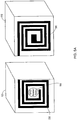
- an RFID tag may comprise electromagnetically responsive materials (e.g., a resonance-based RFID tag) that produce a unique resonance response to a query from an RFID reader.
- each RFID tag may comprise metal strips having unique resonance characteristics that are identifiable by an RFID reader.
- the lengths and/or widths of the metal strip(s) may vary between RFID tags rendering them uniquely identifiable. Combining the metal strips of two different RFID tags to form a combined RFID tag results in a new, unique resonance response that can be detected by the RFID reader.
- the identification code returned from a resonance-based RFID tag may include a spectrally identifiable electromagnetic signal with identifiable peaks and/or valleys at various frequencies.
- the combined RFID tag is formed when the first component and the second component are correctly connected.
- the first and second components are connected incorrectly (e.g., misaligned, connected backwards, not connected at all, connected to the wrong location, etc.)
- the combined RFID tag is not formed.
- an integrated circuit RFID tag portion may not correctly connect to a 3D-printed antenna RFID tag portion if the first and second components are not correctly connected.
- a first 3D-printed component may include an RFID reader that detects other components that each include RFID tags as such other 3D-printed components are connected to the first 3D-printed component.
- a three-dimensional (3D) device may include a first 3D-printed part and a second 3D-printed part.
- the second 3D-printed part may include a radio-frequency identification (RFID) tag that is unreadable when the first 3D-printed part is disconnected from the second 3D-printed part and readable when the first 3D-printed part is connected to the second 3D-printed part.
- RFID reader may be external to the 3D-device or integrated with the 3D-device.
- an RFID reader or an antenna associated therewith may be printed as part of a 3D-printed component.
- a first component may be manufactured (e.g., 3D printed, injection molded, CNC machined, etc.) with a writable RFID tag.
- the system may detect the connection of a second 3D-printed component to the first component and cause an RFID writer device to write assembly information to the writable RFID tag of the first component.
- the system may write assembly information to the writable RFID tag that indicates that the first and second components were once connected, identifies a date the first and second components were connected, specifies a location where the first and second components were connected, and/or identifies an entity (e.g., a user or machine) that connected the first and second components.
- An RFID reader may be used to detect that the first and second components are currently connected and/or read the assembly information to detect that the first and second components were once connected (or other assembly information).
- the writable RFID tag transmits a first identification code with the first component disconnected from the second component and a different identification code with the first component connected to the second component.
- the RFID writer writes assembly information to the writable RFID tag once the first component is connected to the second component, an RFID reader is able to scan the writable RFID tag and determine whether the first component is currently connected or disconnected from the second component and, if the first component is currently disconnected, whether the first component has ever been connected to the second component.
- RFID tags may be embedded within 3D-printed parts or components.
- a system may monitor and record the assembly of a 3D-printed device.
- a 3D-printed device may have an embedded RFID reader and/or writer to monitor and record its own assembly.
- the 3D-printed device may have an integrated antenna or antennas to relay communication from RFID tags to an external RFID reader/writer.
- the system may store connection data to allow for a subsequent audit of the sequence of component assembly and/or indicate the current connection status of the various components of a system.
- a single antenna associated with an RFID reader may be used to monitor multiple connection points.
- the RFID reader may monitor the sequential connections of any number of components to one another and/or to a main or base component.
- an integrated or embedded power source such as a battery or a capacitor, may power the RFID reader.
- the system may detect RFID tags of a first component prior to the connection of the first component to a second component.
- the system may record the number of attempts to connect the first component to the second component.
- the system may detect an attempt to connect the first component to the second component based on, for example, a signal strength of a first identification code received from an RFID tag of the first component.
- the system may provide feedback to the user attempting to connect the first component to the second component.
- the system may include an electronic indicator to provide visual, haptic, or audible feedback encouraging the user to complete the connection or indicating that the connection would be an error.
- the system may visually or audibly prompt the user to press a little harder or listen for a click.
- the RFID tag transmits a second (different) identification code.
- the system may detect the second identification code and provide visual, haptic, or audible feedback that the first and second components have been successfully connected and, in some examples, correctly (or incorrectly) connected.
- 3D-printed devices and components may include 3D-printed metal trace lines (e.g., conductors and antennas) that form, at least portions, of the RFID tags or RFID tag portions on first and second components of a 3D-printed device.
- a main component with an RFID reader or antenna connected to an RFID reader may monitor and facilitate assembly and connection of additional components. The main component may, for example, track and verify the connection of a first component and any number of subsequent connections.
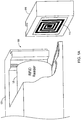
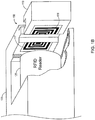
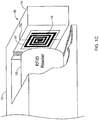
- a male end of a cable may have a first 3D-printed RFID tag portion
- a female end of a cable or port may have a second 3D-printed RFID tag portion.
- a combined RFID tag is formed by the combination of the first 3D-printed RFID tag portion and the second 3D-printed RFID tag portion when the male end of the cable is connected to the female end of a cable or port.
- the RFID reader which may include a 3D-printed antenna, may verify the correct connection of the male end of the cable with the female end of the cable or port.
- a bowl may be too large to 3D print as a single part and so the bowl may be split into multiple portions (e.g., two halves or top, bottom, and middle portions), which can be 3D printed separately and subsequently connected. If the portions are not correctly connected, the bowl may leak or fall apart.
- a first portion of the bowl may be 3D printed with a first embedded RFID tag portion
- a second portion of the bowl may be 3D printed with a second embedded RFID tag portion. Only when the two portions of the bowl are correctly connected do the first and second RFID tag portions form a combined RFID tag that is readable by an RFID reader. Accordingly, an RFID reader can verify the correct assembly of the bowl portions and confirm that the bowl is acceptable for use.
- multiple bowls may be 3D printed and assembled.
- the combined RFID tag formed by the correct assembly of each bowl may transmit a unique identification code. Accordingly, an RFID reader may query a shipment of bowls and verify that all the bows are all correctly assembled and/or identify those that are incorrectly assembled.
- each combined RFID tag may be associated with a particular product serial number or factory location.
- the RFID-based systems and methods described herein can be used by an auditing system to verify that components of a system are correctly assembled and connected.
- An RFID reader may verify that the various components of a system are connected to one another based on an expected set of RFID signals being received from 3D-printed RFID tags formed or enabled by the connected system.
- a system may be formed by joining more than two parts together. For instance, an antenna's length may be extended with each successively connected part, such that an RFID reader may transmit a query signal at different wavelengths to determine how many of the parts are connected together. Different antenna lengths may respond to different wavelengths at varying intensities. Accordingly, The RFID reader may confirm that a target number of parts are connected by detecting the RFID tag formed by the target number of parts forming an antenna with an expected length (and associated frequency response).
- the systems and methods described herein may be utilized to facilitate system servicing or maintenance.
- a technician may be apprised of which of a plurality of connections is incorrect.
- a system may utilize an RFID read to monitor the connections and disconnections of various system components during service or routine maintenance. The system may notify the technician if the wrong component is disconnected (or connected) or, in some examples, provide guided instructions for which component to disassemble (or assemble) next based on the detected sequence of connections (or disconnections) of components.
- a software module or component may include computer instructions or computer-executable code located within a memory device and/or transmitted as electronic signals over a system bus, wired network, or wireless network.
- a software module or component may, for instance, comprise multiple physical or logical blocks of computer instructions, which may be organized as a routine, program, object, component, data structure, etc., that performs tasks or implements particular data types.
- Examples may be provided as a computer program product, including a non-transitory computer and/or machine-readable medium having stored thereon instructions that may be used to program a computer or another electronic device to perform processes described herein.
- a non-transitory computer-readable medium may store instructions that, when executed by a processor of a computer system, cause the processor to perform certain methods disclosed herein.
- the non-transitory computer-readable medium may include, but is not limited to, hard drives, floppy diskettes, optical disks, CD-ROMs, DVD-ROMs, ROMs, RAMs, EPROMs, EEPROMs, magnetic or optical cards, solid-state memory devices, or other types of machine-readable media suitable for storing electronic and/or processor-executable instructions.
- 3D-printing techniques encompass a wide variety of additive manufacturing approaches in which material is added until an object is formed. For example, material may be added by forming several layers of material with each layer stacked on top of the previous layer. Examples of 3D printing techniques include fused filament fabrication, resin-based stereolithography, sintering, melting, or binding powder in layers via selective laser sintering or melting, multijet fusion, metaljet fusion, or the like. Furthermore, as used herein, the concept of 3D-printing encompasses additive processes that include "pick and place" component assembly for integrating additional components, such as semiconductor components, into printed objects and parts.
- Figure 1A illustrates an example block diagram of a first 3D-printed component 110 with an RFID tag 115 to be connected to a second 3D-printed component 120 with an RFID reader 125.
- the example block diagram illustrates the RFID reader 125 as being proximate a connection region 150.
- the RFID reader may be positioned at any location within range to read the RFID tag 115 once the first 3D-printed component 110 is connected to the second 3D-printed component 120.
- the RFID reader 125 may be located external to and remote from the second component 120.
- the RFID reader 125 may be integrated with (internally located or externally affixed) to the second 3D-printed component 120.
- one or more antennas for the RFID reader 125 may be 3D printed during the printing of the first 3D-printed component 110 and/or the second 3D-printed component 120.
- the RFID reader 125 can detect when the first 3D-printed component 110 is connected to the second 3D-printed component 120 at the connection region 150 by reading the RFID tag 115.
- Figure 1B illustrates an example block diagram of the first 3D-printed component 110 with a first 3D-printed RFID tag portion 116 to be connected to a second 3D-printed component 120 with a second 3D-printed RFID tag portion 117 and an RFID reader device 125 integrated (e.g., 3D printed) as part of the second 3D-printed component 120.
- the first 3D-printed component 110 is adapted for connection to the second 3D-printed component 120 at a connection region 150.
- neither the first 3D-printed RFID tag portion 116 nor the second 3D-printed RFID tag portion 117 may be operable to transmit any signal until they are connected (e.g., through an electrical contact connection or a non-contact electromagnetic connection).
- the first 3D-printed RFID tag portion 116 and the second 3D-printed RFID tag portion 117 connect to form a combined RFID tag operable to transmit a signal readable by the RFID reader 125.
- the RFID reader 125 may record the connection of the first 3D-printed component 110 to the second 3D-printed component 120 in a memory or database.
- the memory or database may be internal to the second 3D-printed component 120 or externally located.
- the second 3D-printed component 120 may include a communication port (e.g., wired or wireless) to transmit a confirmation of the connection of the first 3D-printed component 110 to the second 3D-printed component 120 to an external database.
- the RFID reader 125 may periodically query for RFID tags to confirm the connection state of any number of connection regions.
- the connection region 150 may include an electrical contact or switch that is actuated when the first 3D-printed component 110 is connected to the second 3D-printed component 120. The electrical contact or switch, when actuated, may cause the RFID reader 125 to query for RFID tags, such as the combined RFID tag created by the joining of the first 3D-printed RFID tag portion 116 and the second 3D-printed RFID tag portion 117.
- a cabinet may include a plurality of shelves. Each shelf may contain a computing device with a plurality of ports to facilitate, for example, communication and/or provide power to the computing device.
- the cabinet of computing devices may include a large number of ports and associated cables.
- a technician plugging cables into the ports of the computing device may confirm that cables are correctly plugged in by booting the computing device and verifying functionality.
- connectors may include 3D-printed RFID tags and/or portions of 3D-printed RFID tags. An RFID reader may monitor the connection of cables and ports to verify that the correct 3D-printed cables are plugged into the correct 3D-printed ports.
- the presently described systems and methods may be utilized to provide a firewall-friendly installation solution in which the technicians installing cables and computing devices may verify correct connections without accessing secure data and network activity.
- the RFID reader can verify the serial numbers or specific connections that are correctly made without exposing the data transported by the specific connections.
- an RFID reader may be connected to a second network (e.g., a wired or wireless internet of things (“IOT") network), located on the other side of a firewall intended to protect data transmitted by the cables once they are connected.
- IOT internet of things
- original components of an assembly or device may be identified by integrated (e.g., 3D-printed, embedded, or affixed) RFID tags.
- An RFID reader may query the assembly or device to verify that the original components are installed. Unauthorized components and/or counterfeit components may not have RFID tags and/or may have RFID tags that transmit different identification signals.
- Figure 1C illustrates the example block diagram of Figure 1B with the first 3D-printed component 110 correctly connected to the second 3D-printed component 120 such that the first 3D-printed RFID tag portion 116 and the second 3D-printed RFID tag portion 117 combine to form a combined RFID tag readable by the RFID reader 125.
- the first 3D-printed component 110 is correctly connected to the second 3D-printed component 120 at the connection region 150.
- Figure 1D illustrates the example block diagram of Figure 1B with the first 3D-printed component 110 incorrectly connected to the second 3D-printed component 120, visible as a misaligned connection at the connection region 150.
- the combined RFID tag is not formed due to the incorrect connection of the first 3D-printed RFID tag portion 116 and the second 3D-printed RFID tag portion 117.
- the RFID reader 125 may periodically query for RFID tags and fail to detect the expected combined RFID tag that would have been formed by the first 3D-printed RFID tag portion 116 and the second 3D-printed RFID tag portion 117 if the connection had been correctly made.
- the incorrect connection of the first 3D-printed component 110 to the second 3D-printed component 120 may trigger a contact or switch proximate the connection region 150.
- the RFID reader 125 may query for RFID tags in response to the triggering of the electrical contact or switch. If the system fails to detect an RFID tag, the system may transmit an alert (e.g., visual, haptic, or audible) that the connection is incorrect.
- Figure 2 illustrates an example block diagram of a 3D-printed main component 220 with an integrated RFID reader 225 (e.g., including 3D-printed antenna portions) and multiple 3D-printed components 211, 212, and 213 that each includes at least a portion of a 3D-printed RFID tag 215 configured to be mated with a corresponding 3D-printed RFID tag portion 216 on the 3D-printed main component 220.
- the RFID reader 225 of the 3D-printed main component 220 may detect the concurrent or sequential connection of each of the 3D-printed components 211, 212, and 213 to the 3D-printed main component 220.
- unique combined RFID tags are formed by the 3D-printed RFID tags 215 and 216.
- Figure 3A illustrates an example block diagram of a first 3D-printed component 320 with an integrated circuit RFID tag portion 350 and a second 3D-printed component 310 with a 3D-printed antenna RFID tag portion 355.
- a disconnected state neither of the individual RFID tag portions 350 and 355 are operable to transmit a signal.
- An RFID reader will fail to detect a signal from an RFID tag while the first and second 3D-printed components 310 and 320 are in the disconnected state.
- Figure 3B illustrates the block diagram of Figure 3A with the first and second 3D-printed components 310 and 320 connected to form a combined RFID tag with an electrical connection between the integrated circuit RFID tag portion 350 and the 3D-printed antenna RFID tag portion 355.
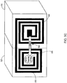
- Figure 3C illustrates the block diagram of Figure 3A with the first and second 3D-printed components 310 and 320 connected to form a combined RFID tag with a non-contact connection between the integrated circuit RFID tag portion 350 and the 3D-printed antenna RFID tag portion 355.
- a small internal antenna of the integrated circuit RFID tag portion 350 may electromagnetically connect to or resonate with the 3D-printed antenna RFID tag portion 355 when it is within a threshold range of the integrated circuit RFID tag portion 350 (e.g., when the first 3D-printed component 320 is connected with the second 3D-printed component 310).
- Figure 4A illustrates a block diagram of a first 3D-printed component 410 with a first 3D-printed RFID tag portion 460 that, by itself, transmits a first identification code 465, and a second 3D-printed component 420 with a second 3D-printed RFID tag portion 450 that, by itself transmits a second identification code 455. Accordingly, with the first 3D-printed component 410 and the second component 420 in a disconnected state, an RFID reader detects each of the first identification code 465 and the second identification code 455 individually.
- Figure 4B illustrates a block diagram the first and second 3D-printed components 410 and 420 connected such that the first and second 3D-printed RFID tag portions 450 and 460 form a combined RFID tag that transmits a third identification code 475 that is different than the first identification code (465, Figure 4A ) and the second identification code (455, Figure 4A ).
- the RFID reader detects the third identification code 475 and thereby validates that the first 3D-printed component 410 and the second 3D-printed component 420 are in a connected state.
- the first RFID tag portion 450 and the second RFID tag portion 460 may each include an integrated circuit component that, by themselves, transmit a unique identification code (455 and 465, in Figure 4A ) via the respective antenna portions.
- the respective integrated circuit components detect the combined antenna portions based on a change in impedance in the connected antenna portions.
- the impedance value associated with the combined RFID tag causes one or both of the integrated circuits to cause the third identification code 475 to be transmitted.
- one or both of the integrated circuit portions may detect that the combined RFID tag is formed based on a detected change in resonance, a change in received power level from a querying RFID reader, communication between the integrated circuits, a change in capacitance, a change in inductance, a change in resistance, or the like.
- Figure 5A illustrates a block diagram of first 3D-printed component 510 with a first 3D-printed RFID tag portion 560 that comprises a writable RFID tag.
- a second 3D-printed component 520 includes a second 3D-printed RFID tag portion 550 and an integrated RFID reader/writer 555.
- Each of the first, writable RFID tag portion 560 and the second, RFID tag portion 550 may be fully operational as an RFID tag in the disconnected state.
- Figure 5B illustrates the block diagram of Figure 5A with the RFID reader/writer 555 reading a first identification code 565 of the first, writable RFID tag portion 560 of the first component 510 in the disconnected state.
- Figure 5C illustrates the block diagram of Figure 5A with the RFID reader/writer 555 reading a second identification code 566 of the first, writable RFID tag portion 560 of the first component 510 in a connected state.
- Figure 5D illustrates the block diagram of Figure 5A with the RFID reader/writer 555 writing assembly information 557 to the first, writable RFID tag portion 560 of the first component 510.
- the RFID reader/writer 555 may write assembly information to the first, writable RFID tag portion 560 that indicates that the first and second components 510 and 520 were once connected, identifies a date the first and second components 510 and 520 were connected, specifies a location (e.g., coordinates) where the first and second components 510 and 520 were connected, and/or identifies an entity (e.g., a user, machine, facility, etc.) that connected the first and second components 510 and 520.
- an entity e.g., a user, machine, facility, etc.
- An RFID reader (such as the RFID reader/writer 555 or a different RFID reader) may detect that the first and second components 510 and 520 are currently connected and/or read the assembly information to detect that the first and second components 510 and 520 were once connected and/or obtain other assembly information.
- the first, writable RFID tag portion 560 transmits a first identification code while the first component is disconnected from the second component ( Figure 5B ) and a different identification code while the first component is connected to the second component ( Figure 5C ).
- the RFID reader/writer 555 writes assembly information to the first, writable RFID tag portion 560 once the first component 510 is connected to the second component 520, an RFID reader is able to scan the first, writable RFID tag portion 560 and determine whether the first component 510 is currently connected or disconnected from the second component 520 and, if the first component 510 is currently disconnected, whether the first component 510 has ever been connected to the second component 520.
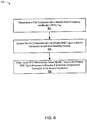
- Figure 6 illustrates a flow chart of a method 600 to detect that the first component is connected to the second component.
- a first component may be manufactured, at 602, with an integrated writable RFID tag.
- a writable RFID tag may be embedded within or affixed to a 3D-printed part.
- a writable RFID tag or at least an antenna portion thereof may itself be 3D-printed.
- the first component may be connected, at 604, to a second component as part of an assembly process.
- An RFID writer device e.g., an RFID reader/writer or a stand-alone writing device
- the assembly information may, for example, include any combination of a date the first and second components were connected, identification of a location where the first and second components were connected, and identification of an entity that connected the first and second components.
- the writable RFID tag Prior to having the assembly information written to the writable RFID tag, the writable RFID tag may be configured to transmit a first identification signal with the first component disconnected from the second component and transmit a second identification signal with the first component connected to the second component.
- the writable RFID tag portion may transmit the assembly information in addition to the first and second identification signals based on the connection state. Accordingly, the system may verify, via an RFID reader, that the first and second components are currently disconnected based on receiving the first identification signal, but that the first and second components have been connected in the past (i.e., previously connected) based on received assembly information.
- the writable RFID tag portion may transmit the assembly information instead of the first and second identification signals regardless of the connection state.
Landscapes
- Engineering & Computer Science (AREA)
- Physics & Mathematics (AREA)
- Microelectronics & Electronic Packaging (AREA)
- General Physics & Mathematics (AREA)
- Theoretical Computer Science (AREA)
- Computer Hardware Design (AREA)
- Health & Medical Sciences (AREA)
- Toxicology (AREA)
- Computer Networks & Wireless Communication (AREA)
- Electromagnetism (AREA)
- General Health & Medical Sciences (AREA)
- Artificial Intelligence (AREA)
- Computer Vision & Pattern Recognition (AREA)
- Near-Field Transmission Systems (AREA)
Priority Applications (3)
| Application Number | Priority Date | Filing Date | Title |
|---|---|---|---|
| EP20290017.1A EP3869408A1 (fr) | 2020-02-20 | 2020-02-20 | Composants imprimés en 3d avec détection de connexion rfid |
| US17/904,334 US20230067534A1 (en) | 2020-02-20 | 2021-01-12 | 3d-printed components with rfid connection detection |
| PCT/US2021/013075 WO2021167716A1 (fr) | 2020-02-20 | 2021-01-12 | Éléments imprimés en 3d à détection de liaison rfid |
Applications Claiming Priority (1)
| Application Number | Priority Date | Filing Date | Title |
|---|---|---|---|
| EP20290017.1A EP3869408A1 (fr) | 2020-02-20 | 2020-02-20 | Composants imprimés en 3d avec détection de connexion rfid |
Publications (1)
| Publication Number | Publication Date |
|---|---|
| EP3869408A1 true EP3869408A1 (fr) | 2021-08-25 |
Family
ID=70480183
Family Applications (1)
| Application Number | Title | Priority Date | Filing Date |
|---|---|---|---|
| EP20290017.1A Pending EP3869408A1 (fr) | 2020-02-20 | 2020-02-20 | Composants imprimés en 3d avec détection de connexion rfid |
Country Status (3)
| Country | Link |
|---|---|
| US (1) | US20230067534A1 (fr) |
| EP (1) | EP3869408A1 (fr) |
| WO (1) | WO2021167716A1 (fr) |
Citations (3)
| Publication number | Priority date | Publication date | Assignee | Title |
|---|---|---|---|---|
| FR3006479A1 (fr) * | 2013-06-04 | 2014-12-05 | Editag | Systeme de radio-identification modulaire avec module rfid passif et module rfid actif |
| US20160110639A1 (en) * | 2014-08-10 | 2016-04-21 | David Finn | Passive smart cards, metal cards, payment objects and smart jewelry |
| US20190130238A1 (en) * | 2016-04-05 | 2019-05-02 | Hewlett-Packard Development Company, L.P. | Modular radio frequency identification (rfid) devices |
Family Cites Families (10)
| Publication number | Priority date | Publication date | Assignee | Title |
|---|---|---|---|---|
| US20070159337A1 (en) * | 2006-01-12 | 2007-07-12 | Sdgi Holdings, Inc. | Modular RFID tag |
| US9563984B2 (en) * | 2014-04-02 | 2017-02-07 | Autodesk, Inc. | Integrating components into 3D printed objects |
| US9656428B2 (en) * | 2014-09-09 | 2017-05-23 | Disney Enterprises, Inc. | Three dimensional (3D) printed objects with embedded identification (ID) elements |
| US11648731B2 (en) * | 2015-10-29 | 2023-05-16 | Hewlett-Packard Development Company, L.P. | Forming three-dimensional (3D) printed electronics |
| WO2018160287A1 (fr) * | 2017-03-01 | 2018-09-07 | Walmart Apollo, Llc | Systèmes, dispositifs et procédés pour former des produits tridimensionnels dans lesquels des éléments rfid sont intégrés |
| WO2019013774A1 (fr) * | 2017-07-12 | 2019-01-17 | Hewlett-Packard Development Company, L.P. | Identifiants sphériques |
| EP3572217A1 (fr) * | 2018-05-24 | 2019-11-27 | Fundació Institut de Ciències Fotòniques | Procédé, système et ensemble de fabrication d'un composite électroconducteur |
| US10821350B1 (en) * | 2018-08-28 | 2020-11-03 | The Last Gameboard, INc. | Smart game board |
| US10402711B1 (en) * | 2018-11-21 | 2019-09-03 | Konica Minolta Laboratory U.S.A., Inc. | Combined RFID tag assembly |
| DE102022113080A1 (de) * | 2022-05-24 | 2023-11-30 | Sick Ag | Sicherheitszuhaltung |
-
2020
- 2020-02-20 EP EP20290017.1A patent/EP3869408A1/fr active Pending
-
2021
- 2021-01-12 US US17/904,334 patent/US20230067534A1/en not_active Abandoned
- 2021-01-12 WO PCT/US2021/013075 patent/WO2021167716A1/fr active Application Filing
Patent Citations (3)
| Publication number | Priority date | Publication date | Assignee | Title |
|---|---|---|---|---|
| FR3006479A1 (fr) * | 2013-06-04 | 2014-12-05 | Editag | Systeme de radio-identification modulaire avec module rfid passif et module rfid actif |
| US20160110639A1 (en) * | 2014-08-10 | 2016-04-21 | David Finn | Passive smart cards, metal cards, payment objects and smart jewelry |
| US20190130238A1 (en) * | 2016-04-05 | 2019-05-02 | Hewlett-Packard Development Company, L.P. | Modular radio frequency identification (rfid) devices |
Also Published As
| Publication number | Publication date |
|---|---|
| WO2021167716A1 (fr) | 2021-08-26 |
| US20230067534A1 (en) | 2023-03-02 |
Similar Documents
| Publication | Publication Date | Title |
|---|---|---|
| EP2630613B1 (fr) | Système rfid de suivi d'un équipement placé sur un bâti | |
| AU2007313908B2 (en) | A system for detecting and communicating with RFID memory devices | |
| US8044804B1 (en) | Localizing a tag using variable signal range | |
| KR100655982B1 (ko) | Ic태그 실장하네스 및 실장방법 | |
| US7423547B2 (en) | System and method for verifying assembly of manufactured parts using RFID tags | |
| JP6151720B2 (ja) | 無線周波数認識(rfid)接続タグ通信プロトコル及び関連システムと方法 | |
| EP3544114B1 (fr) | Système de vérification de connexion radio fréquence de résonance | |
| JP6333735B2 (ja) | 複数の無線周波数認識(rfid)接続タグと1つ以上のデバイスの間の通信並びに関連システム及び方法 | |
| WO2009105505A2 (fr) | Procédé et appareil de suivi d'articles rfid | |
| EP2810450B1 (fr) | Protocole pour des communications entre une étiquette d'identification radiofréquence (rfid) et un dispositif connecté, et systèmes et procédés associés | |
| US11039538B2 (en) | Communication system including antennas on flexible circuit board | |
| EP3869408A1 (fr) | Composants imprimés en 3d avec détection de connexion rfid | |
| CN102289638A (zh) | 从水下组件获得数据 | |
| CN101685495A (zh) | 标签识别方法及读写器和射频识别系统 | |
| EP1818859B1 (fr) | Etiquettes RFID montées sur les connecteurs d'un faisceau et procédé de montage d'un faisceau | |
| CN110542882A (zh) | 基于rfid的抽屉内物品位置计算方法 | |
| JP2023152143A (ja) | アンテナ、リーダライタシステム、及びリーダライタ | |
| US11808392B2 (en) | Connection verifier | |
| EP3290948A1 (fr) | Capteur et systeme de determination de position | |
| CN105424222A (zh) | 一种基于射频识别技术的多目标温度状态监测系统和方法 | |
| JP2007094886A (ja) | 無線タグリーダ/ライタ及び無線タグリード/ライト方法 | |
| TW201504950A (zh) | 射頻識別(rfid)標籤事件發生之偵測、報告與監控以及相關的rfid讀取器、系統與方法 | |
| CN115829215A (zh) | 容器出入库管理方法、系统、存储介质及电子设备 | |
| CN203456574U (zh) | 用于内模具检测的rfid天线 |
Legal Events
| Date | Code | Title | Description |
|---|---|---|---|
| PUAI | Public reference made under article 153(3) epc to a published international application that has entered the european phase |
Free format text: ORIGINAL CODE: 0009012 |
|
| STAA | Information on the status of an ep patent application or granted ep patent |
Free format text: STATUS: REQUEST FOR EXAMINATION WAS MADE |
|
| 17P | Request for examination filed |
Effective date: 20200227 |
|
| AK | Designated contracting states |
Kind code of ref document: A1 Designated state(s): AL AT BE BG CH CY CZ DE DK EE ES FI FR GB GR HR HU IE IS IT LI LT LU LV MC MK MT NL NO PL PT RO RS SE SI SK SM TR |
|
| RIN1 | Information on inventor provided before grant (corrected) |
Inventor name: BALLAGAS, RAFAEL Inventor name: DANEY DE MARCILLAC, PATRICK JACQUES ANDRE MARIE Inventor name: ALLEN, WILLIAM Inventor name: SAYERS, CRAIG PETER |
|
| STAA | Information on the status of an ep patent application or granted ep patent |
Free format text: STATUS: EXAMINATION IS IN PROGRESS |
|
| 17Q | First examination report despatched |
Effective date: 20230414 |
|
| GRAP | Despatch of communication of intention to grant a patent |
Free format text: ORIGINAL CODE: EPIDOSNIGR1 |
|
| STAA | Information on the status of an ep patent application or granted ep patent |
Free format text: STATUS: GRANT OF PATENT IS INTENDED |
|
| INTG | Intention to grant announced |
Effective date: 20240514 |