EP3869311A1 - Setting value change device - Google Patents
Setting value change device Download PDFInfo
- Publication number
- EP3869311A1 EP3869311A1 EP21167373.6A EP21167373A EP3869311A1 EP 3869311 A1 EP3869311 A1 EP 3869311A1 EP 21167373 A EP21167373 A EP 21167373A EP 3869311 A1 EP3869311 A1 EP 3869311A1
- Authority
- EP
- European Patent Office
- Prior art keywords
- drag
- movement path
- button
- display
- setting value
- Prior art date
- Legal status (The legal status is an assumption and is not a legal conclusion. Google has not performed a legal analysis and makes no representation as to the accuracy of the status listed.)
- Granted
Links
Images








Classifications
-
- G—PHYSICS
- G06—COMPUTING OR CALCULATING; COUNTING
- G06F—ELECTRIC DIGITAL DATA PROCESSING
- G06F3/00—Input arrangements for transferring data to be processed into a form capable of being handled by the computer; Output arrangements for transferring data from processing unit to output unit, e.g. interface arrangements
- G06F3/01—Input arrangements or combined input and output arrangements for interaction between user and computer
- G06F3/048—Interaction techniques based on graphical user interfaces [GUI]
- G06F3/0484—Interaction techniques based on graphical user interfaces [GUI] for the control of specific functions or operations, e.g. selecting or manipulating an object, an image or a displayed text element, setting a parameter value or selecting a range
- G06F3/0486—Drag-and-drop
-
- F—MECHANICAL ENGINEERING; LIGHTING; HEATING; WEAPONS; BLASTING
- F24—HEATING; RANGES; VENTILATING
- F24D—DOMESTIC- OR SPACE-HEATING SYSTEMS, e.g. CENTRAL HEATING SYSTEMS; DOMESTIC HOT-WATER SUPPLY SYSTEMS; ELEMENTS OR COMPONENTS THEREFOR
- F24D5/00—Hot-air central heating systems; Exhaust gas central heating systems
- F24D5/12—Hot-air central heating systems; Exhaust gas central heating systems using heat pumps
-
- F—MECHANICAL ENGINEERING; LIGHTING; HEATING; WEAPONS; BLASTING
- F24—HEATING; RANGES; VENTILATING
- F24D—DOMESTIC- OR SPACE-HEATING SYSTEMS, e.g. CENTRAL HEATING SYSTEMS; DOMESTIC HOT-WATER SUPPLY SYSTEMS; ELEMENTS OR COMPONENTS THEREFOR
- F24D5/00—Hot-air central heating systems; Exhaust gas central heating systems
-
- F—MECHANICAL ENGINEERING; LIGHTING; HEATING; WEAPONS; BLASTING
- F24—HEATING; RANGES; VENTILATING
- F24F—AIR-CONDITIONING; AIR-HUMIDIFICATION; VENTILATION; USE OF AIR CURRENTS FOR SCREENING
- F24F11/00—Control or safety arrangements
-
- F—MECHANICAL ENGINEERING; LIGHTING; HEATING; WEAPONS; BLASTING
- F24—HEATING; RANGES; VENTILATING
- F24F—AIR-CONDITIONING; AIR-HUMIDIFICATION; VENTILATION; USE OF AIR CURRENTS FOR SCREENING
- F24F11/00—Control or safety arrangements
- F24F11/89—Arrangement or mounting of control or safety devices
-
- F—MECHANICAL ENGINEERING; LIGHTING; HEATING; WEAPONS; BLASTING
- F24—HEATING; RANGES; VENTILATING
- F24H—FLUID HEATERS, e.g. WATER OR AIR HEATERS, HAVING HEAT-GENERATING MEANS, e.g. HEAT PUMPS, IN GENERAL
- F24H1/00—Water heaters, e.g. boilers, continuous-flow heaters or water-storage heaters
-
- F—MECHANICAL ENGINEERING; LIGHTING; HEATING; WEAPONS; BLASTING
- F24—HEATING; RANGES; VENTILATING
- F24H—FLUID HEATERS, e.g. WATER OR AIR HEATERS, HAVING HEAT-GENERATING MEANS, e.g. HEAT PUMPS, IN GENERAL
- F24H1/00—Water heaters, e.g. boilers, continuous-flow heaters or water-storage heaters
- F24H1/18—Water-storage heaters
-
- G—PHYSICS
- G06—COMPUTING OR CALCULATING; COUNTING
- G06F—ELECTRIC DIGITAL DATA PROCESSING
- G06F3/00—Input arrangements for transferring data to be processed into a form capable of being handled by the computer; Output arrangements for transferring data from processing unit to output unit, e.g. interface arrangements
- G06F3/01—Input arrangements or combined input and output arrangements for interaction between user and computer
- G06F3/048—Interaction techniques based on graphical user interfaces [GUI]
- G06F3/0484—Interaction techniques based on graphical user interfaces [GUI] for the control of specific functions or operations, e.g. selecting or manipulating an object, an image or a displayed text element, setting a parameter value or selecting a range
- G06F3/04847—Interaction techniques to control parameter settings, e.g. interaction with sliders or dials
-
- G—PHYSICS
- G06—COMPUTING OR CALCULATING; COUNTING
- G06F—ELECTRIC DIGITAL DATA PROCESSING
- G06F3/00—Input arrangements for transferring data to be processed into a form capable of being handled by the computer; Output arrangements for transferring data from processing unit to output unit, e.g. interface arrangements
- G06F3/01—Input arrangements or combined input and output arrangements for interaction between user and computer
- G06F3/048—Interaction techniques based on graphical user interfaces [GUI]
- G06F3/0487—Interaction techniques based on graphical user interfaces [GUI] using specific features provided by the input device, e.g. functions controlled by the rotation of a mouse with dual sensing arrangements, or of the nature of the input device, e.g. tap gestures based on pressure sensed by a digitiser
- G06F3/0488—Interaction techniques based on graphical user interfaces [GUI] using specific features provided by the input device, e.g. functions controlled by the rotation of a mouse with dual sensing arrangements, or of the nature of the input device, e.g. tap gestures based on pressure sensed by a digitiser using a touch-screen or digitiser, e.g. input of commands through traced gestures
-
- G—PHYSICS
- G06—COMPUTING OR CALCULATING; COUNTING
- G06F—ELECTRIC DIGITAL DATA PROCESSING
- G06F3/00—Input arrangements for transferring data to be processed into a form capable of being handled by the computer; Output arrangements for transferring data from processing unit to output unit, e.g. interface arrangements
- G06F3/01—Input arrangements or combined input and output arrangements for interaction between user and computer
- G06F3/048—Interaction techniques based on graphical user interfaces [GUI]
- G06F3/0487—Interaction techniques based on graphical user interfaces [GUI] using specific features provided by the input device, e.g. functions controlled by the rotation of a mouse with dual sensing arrangements, or of the nature of the input device, e.g. tap gestures based on pressure sensed by a digitiser
- G06F3/0488—Interaction techniques based on graphical user interfaces [GUI] using specific features provided by the input device, e.g. functions controlled by the rotation of a mouse with dual sensing arrangements, or of the nature of the input device, e.g. tap gestures based on pressure sensed by a digitiser using a touch-screen or digitiser, e.g. input of commands through traced gestures
- G06F3/04883—Interaction techniques based on graphical user interfaces [GUI] using specific features provided by the input device, e.g. functions controlled by the rotation of a mouse with dual sensing arrangements, or of the nature of the input device, e.g. tap gestures based on pressure sensed by a digitiser using a touch-screen or digitiser, e.g. input of commands through traced gestures for inputting data by handwriting, e.g. gesture or text
-
- Y—GENERAL TAGGING OF NEW TECHNOLOGICAL DEVELOPMENTS; GENERAL TAGGING OF CROSS-SECTIONAL TECHNOLOGIES SPANNING OVER SEVERAL SECTIONS OF THE IPC; TECHNICAL SUBJECTS COVERED BY FORMER USPC CROSS-REFERENCE ART COLLECTIONS [XRACs] AND DIGESTS
- Y02—TECHNOLOGIES OR APPLICATIONS FOR MITIGATION OR ADAPTATION AGAINST CLIMATE CHANGE
- Y02B—CLIMATE CHANGE MITIGATION TECHNOLOGIES RELATED TO BUILDINGS, e.g. HOUSING, HOUSE APPLIANCES OR RELATED END-USER APPLICATIONS
- Y02B30/00—Energy efficient heating, ventilation or air conditioning [HVAC]
- Y02B30/13—Hot air central heating systems using heat pumps
Definitions
- the present invention relates to a setting value change device for changing a desired temperature of a refrigeration apparatus and/or a heating apparatus or a desired hot water amount of a hot water supply device.
- setting value change devices for changing desired temperature s of refrigeration apparatuses such as heat pump systems or desired hot water amounts of hot water supply devices.
- Examples thereof include a remote control device of a heat pump system, and smartphones and tablet computers that connect to the heat pump system via communication means described in Patent Document 1 (Japanese Unexamined Patent Application Publication No. 2015-114057 ).
- Some of these setting value change devices include a touchscreen device having both display and touch sensor functions, and it is possible to change the desired temperature using the touchscreen device.
- the remote control device described in Patent Document 1 the set temperature is changed mainly using tap input or toggle input, in which touch keys are pressed.
- An object of the present invention is to provide a setting value change device that facilitates change operations to correct temperature setting values or hot water amount setting values by drag operations.
- a setting value change device performs change processing to change a temperature setting value of a refrigeration apparatus and/or a heating apparatus.
- the setting value change device includes a display that displays the temperature setting value; a touch sensor that detects a touch operation on the display, the touch sensor arranged and configured to transmit a display on the display; and a controller connected to the display and the touch sensor.
- the controller performs change processing to cause the display to display a drag button and a movement path on which the drag button moves; provide, on the touch sensor, a drag area that detects a drag input on the drag button and a reference point disposed at a location off the movement path; set the drag area larger than a display range of the movement path; and move the drag button to a crossing point where a straight line or a specific curve connecting the reference point to a drag operation position in the drag area crosses the movement path, and change the temperature setting value to a value corresponding to a position of the drag button.
- the controller performs change processing to set the drag area larger than the display range of the movement path, move the drag button to the crossing point where the straight line or specific curve connecting the reference point to the drag operation position in the drag area crosses the movement path, and change the temperature setting value to the value corresponding to the position of the drag button.
- a setting value change device is the setting value change device according to the first aspect, wherein the controller causes the display to display an operation button near the movement path; performs settings to enable the touch sensor to detect and input a touch operation on the operation button; and, when the drag button is being dragged, expands the drag area up to a range in which the operation button is displayed so that a change operation of the temperature setting value is continued even if there is a touch operation on the operation button.
- the drag area is expanded up to the range in which the operation button is displayed so that the change operation of the temperature setting value is continued even if there is a touch operation on the operation button.
- a wide drag area can be obtained even when the operation button is set, and erroneous input caused by touch operations of the operation button can be reduced.
- drag operations are facilitated and it is easier to perform correct change operations of the temperature setting value.
- a setting value change device is the setting value change device according to the first or second aspect, wherein the controller sets a cancel area such that the cancel area is touched at a time of the drag operation of the drag button, the change processing of the temperature setting value is not continued.
- the change processing of the temperature setting value is not continued when the cancel area is touched during the drag operation of the drag button, and the temperature setting is completed at the timing. As such, changes to unintended temperature setting values resulting from drag operations to points beyond the end of the cancel area are eliminated.
- a setting value change device is the setting value change device according to the third aspect, wherein the controller causes the display to display the movement path as a non-linear shape; associates a value from when a position of the drag button is at a one end of the movement path with a lower limit value of the temperature setting value; associates a value from when the position of the drag button is at the other end of the movement path with an upper limit value of the temperature setting value; and sets the cancel area to a range connecting a periphery of the one end of the movement path to a periphery of the other end of the movement path.
- the cancel area is set to the range connecting the periphery of the one end of the movement path to the periphery of the other end of the movement path.
- a setting value change device is the setting value change device according to the fourth aspect, wherein the controller disposes the cancel area so as to cross the straight line connecting the one end of the movement path to the other end of the movement path.
- the cancel area is provided so as to cross the straight line connecting the one end to the other end, and this configuration results in a high probability of reducing misoperations such as changing to a value near the lower limit value when intending to change to a value near the upper limit value and changing to a value near the upper limit value when intending to change to a value near the lower limit value.
- a setting value change device is the setting value change device according to the fourth or fifth aspect, wherein the controller causes the display to display the movement path as a circular arc shape or an elliptical arc shape; and disposes the cancel area at a position surrounded by the movement path.
- the drag button when moving the drag button along the movement path that is formed in the circular arc shape or the elliptical arc shape, there are cases where the drag operation is ended while moving the drag operation position toward the inside of the arc.
- the cancel area is disposed at the position surrounded by the movement path.
- misoperations such as changing to a value near the lower limit value when intending to change to a value near the upper limit value and changing to value near the upper limit value when intending to change to a value near the lower limit value can be reduced by the cancel area that is disposed at the position inside the arc surrounded by the circular arc-shaped or elliptical arc-shaped movement path.
- a setting value change device is the setting value change device according to any one of the fourth to sixth aspects, wherein the controller disposes the cancel area in a range including a line segment connecting the middle of the one end of the movement path and the other end of the movement path to the reference point.
- the cancel area is disposed in the range including the line segment connecting the middle of the one end of the movement path and the other end of the movement path to the reference point.
- a setting value change device is the setting value change device according to the seventh aspect, wherein the controller sets a shape of the cancel area such that a length in a direction along the line segment is longer than a length in a direction connecting the one end to the other end.
- the shape of the cancel area is set such that the length in the direction along the line segment is longer than the length in the direction connecting the one end to the other end.
- a setting value change device is the setting value change device according to any one of the first to eighth aspects wherein, prior to the drag button being touched, the controller sets the drag area to a range smaller than the display range of the movement path including the display range of the drag button; and, after the drag operation of the drag button has started, the controller expands the drag area to set the drag area larger than the display range of the movement path.
- the controller expands the drag area to set the drag area larger than the display range of the movement path.
- the dispose the operation button for example, in the drag area of the expanded portion before and after the performance of the drag operation, thereby making the performance of operations other than the drag operation easier.
- a setting value change device performs change processing to change a hot water amount setting value of a hot water supply device.
- the setting value change device includes a display that displays the hot water amount setting value; a touch sensor that detects a touch operation on the display, the touch sensor arranged and configured to transmit a display on the display; and a controller connected to the display and the touch sensor.
- the controller performs change processing to cause the display to display a drag button and a movement path on which the drag button moves; provide a drag area that detects a drag input on the drag button and a reference point disposed at a location off the movement path; set the drag area larger than the display range of the movement path; and move the drag button to a crossing point where a straight line or a specific curve connecting the reference point to a drag operation position in the drag area crosses the movement path, and change the hot water amount setting value to a value corresponding to a position of the drag button.
- the controller performs change processing to set the drag area larger than the display range of the movement path, move the drag button to the crossing point where the straight line or specific curve connecting the reference point to the drag operation position in the drag area crosses the movement path, and change the hot water amount setting value to the value corresponding to the position of the drag button.
- the setting value change device it is possible to mitigate the risk of a significant temperature difference occurring between the set temperature and the temperature intended to be set due to mistakenly inputting a value near the lower limit value instead of a value near the upper limit value of the temperature setting value, or mistakenly inputting a value near the upper limit value instead of a value near the lower limit value of the temperature setting value.
- the feature for reducing the significant temperature difference from occurring between the set temperature and the temperature intended to be set is enhanced.
- the setting value change device when the movement path is the circular arc shape or the elliptical arc shape, the feature for reducing the significant temperature difference from occurring between the set temperature and the temperature intended to be set is significantly enhanced.
- the feature for reducing a significant temperature difference from occurring between the set temperature and the temperature intended to be set is significantly enhanced.
- an air conditioning system 100 includes a mobile terminal 50.
- the mobile terminal 50 specifically is a smartphone 500.
- FIG. 1 illustrates the overall configuration of the air conditioning system 100.
- the air conditioning system 100 is a system for acquiring information of desired air conditioners 10a and 10b from the mobile terminal 50 possessed by a user and operating the desired air conditioners 10a and 10b, via a server 40 and adapters 20a and 20b that function as information mediation devices.
- a router 21 is installed in a building 30.
- the router 21 connects a local area network (hereinafter referred to as a "LAN") 81 installed in the building 30 to a public line 80 including the Internet.
- the LAN 81 is a wireless LAN that uses the functions of the router 21.
- the adapters 20a and 20b that are connected by wires to the air conditioners 10a and 10b are connected wirelessly to the LAN 81.
- network devices such as personal computers and printers (not illustrated in the drawings) used in the building 30 may also be connected to the LAN 81.
- each of the air conditioners 10a and 10b must be registered in advance in the server 40.
- an actual air conditioning system 100 includes the air conditioners 10a and 10b scattered throughout a plurality of buildings 30.
- the server 40 installed remotely from the building 30 is operated, via the public line 80, by a manufacturer, sales company, or maintenance company of air conditioners, and information of the air conditioners in multiple buildings 30 is accumulated in the server 40.
- the two air conditioners 10a and 10b and the two adapters 20a and 20b are an installation example of the air conditioners and adapters installed in the building 30, and configurations are possible in which one air conditioner or three or more air conditioners are provided and/or one adapter or three or more adapters are provided.
- the air conditioners 10a and 10b are include indoor units 11a and 11b and outdoor units 12a and 12b.
- the indoor units 11a and 11b are installed in rooms 30a and 30b of the building 30.
- the outdoor units 12a and 12b are installed outside the building 30.
- the indoor units 11a and 11b are connected on a one-to-one basis to the adapters 20a and 20b (described later).
- the air conditioner 10a and the air conditioner 10b have the same fundamental configuration and, as such, the air conditioner 10a is used as an example in the following description.
- the indoor unit 11a and the outdoor unit 12a are connected to each other via a refrigerant pipe, which forms part of a refrigeration circuit that includes a compressor, a heat exchanger, and the like (not illustrated in the drawings).
- the air conditioner 10a has a variety of sensors.
- the indoor unit 11a has an indoor temperature sensor 14a that detects the temperature of the room 30a in which the indoor unit 11a is installed.
- the outdoor unit 12a has an outside air temperature sensor 14b that detects the temperature of outside air near the building 30.
- the air conditioner 10a has a control unit 13.
- the control unit 13 includes control units of the indoor unit 11a and the outdoor unit 12a of the air conditioner 10a.
- the control unit 13 controls the operation of the air conditioner 10a, that is, controls the actions of the compressor and other components of the refrigeration circuit, in accordance with operation commands input, via a remote controller 15, into the air conditioner 10a by a user in the room 30a.
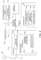
- control unit 13 sends device data 25a related to the air conditioner 10a to the adapter 20a.
- the control unit 13 sends, to the adapter 20a, data indicating the content of a control command for the indoor unit 11a, input via the remote controller 15.
- the "data indicating the content of an operation command” is an operation start/operation stop, operation mode (cooling mode, heating mode, blowing mode, and the like), set temperature, and the like of the air conditioner 10a.
- the device data 25a sent to the adapter 20a includes possessed function information 18a (described later), cumulative operating time 18b, power consumption 18c, and the like.
- control unit 13 sends, to the adapter 20a, temperature data 25b related to the indoor temperature and the outside air temperature. Specifically, the control unit 13 sends, to the adapter 20a, room temperature data detected by the indoor temperature sensor 14a and outside air temperature data detected by the outside air temperature sensor 14b.
- control unit 13 executes control commands sent from the adapter 20a.
- the "control commands sent from the adapter 20a" includes commands ordering the sending of operation commands for the indoor unit 11a and/or specific device data to the adapter 20a.
- the control unit 13 is provided with a CPU and a storage unit 18 including RAM and ROM.
- the possessed function information 18a is stored in the ROM, and the cumulative operating time 18b, the power consumption 18c, and the like are stored in the RAM
- the cumulative operating time 18b is the cumulative operating time of the air conditioner 10a, as counted by a timer 17.
- the power consumption 18c is the power consumed by the air conditioner 10a, as measured by a power meter 14d.
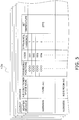
- the possessed function information 18a is information related to functions possessed by the air conditioner 10a. As illustrated in FIG. 4 , the possessed function information 18a is information that distinguishes between functions actually possessed and functions not possessed by the air conditioner 10a of a plurality of functions with which an air conditioner can be provided. In the air conditioning system 100, the possessed function information 18a includes first information (code XX1 in FIG. 4 ), second information (code XX2 in FIG. 4 ), third information (code XX3 in FIG. 4 ), fourth information (code XX4 in FIG. 4 ), and fifth information (code XXX in FIG. 4 ). In one example, the first information is information of whether the air conditioner 10a has a time measurement function to measure the cumulative operating time.
- the air conditioner 10a is not provided with a function to perform laundry drying operations, a function to change wind direction by remote control, or a person detection function, and is provided with the function to measure cumulative operating time and a function to measure power consumption.
- the possessed function information 18a is sent to the adapter 20a as a portion of the device data 25a, and is stored in a storage unit 24a of the adapter 20a.
- the information mediation devices are devices that use the public line 80 to enable exchange of information between the air conditioners 10a and 10b and the mobile terminal 50.
- the information mediation devices include the adapters 20a and 20b, the router 21, and the server 40.
- the adapters 20a and 20b are network adapters for connecting the air conditioners 10a and 10b to the LAN 81.
- the adapter 20a and the adapter 20b have the same fundamental configuration and, as such, the adapter 20a is used as an example in the following description.
- the adapter 20a includes a CPU, a wireless communication unit 22a, and a storage unit 24a.
- the adapter 20a has a communication function to eliminate phase differences in communication protocols between networks and also a control function to control the air conditioners 10a and 10b.
- the adapter 20a is connected by wire to the control unit 13 of the indoor unit 11a, and receives power from the indoor unit 11a to operate (not illustrated in the drawings).
- the device data 25a, the temperature data 25b, and the like are stored in the storage unit 24a.
- these pieces of data 25a and 25b are pieces of data related to the air conditioner 10a that are sent from the air conditioner 10a to the adapter 20a.
- the adapter 20a periodically (every one minute in this case) compiles these pieces of data 25a and 25b as information of the air conditioner 10a and sends the compiled information to the server 40 via the public line 80.
- a server address is stored in advance in the storage unit 24a.
- a device ID allocated to the adapter 20a by the server 40 is also stored in the storage unit 24a.
- the device ID which is an identification code of the adapter 20a, is information whereby the server 40 uniquely identifies the adapter 20a.
- the router 21 is a communication device that has a WAN side interface and a LAN side interface and that connects these two networks to each other.
- the router 21 automatically detects the presence of the adapters 20a and 20b when the adapters 20a and 20b are connected to the LAN 81, and registers network information of the adapters 20a and 20b.
- the adapters 20a and 20b enable communication with the other network devices on the LAN 81 and network devices on the public line 80 (on the Internet).
- the router 21 fulfills the role of constructing the LAN 81 in the building 30.
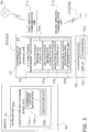
- the server 40 is a computer that is provided on the public line 80 (on the Internet) to perform air conditioning management services, and that runs server software. As illustrated in FIG. 3 , the server 40 has a storage unit 43.
- the storage unit 43 has a database for accumulating a variety of data related to the air conditioners 10a and 10b. Specifically, the storage unit 43 has an adapter-specific database 43a.
- the server 40 accumulates, by adapter, the device data 25a, the temperature data 25b and the like of the air conditioner. The device data 25a, the temperature data 25b and the like are sent periodically from the adapter 20a.
- the variety of data related to the air conditioners 10a and 10b is stored in the adapter-specific database 43a in a manner associated with the device IDs allocated to the adapters 20a and 20b connected to the air conditioners 10a and 10b.
- the server 40 identifies both of the adapters 20a and 20b as related adapters that are related to each other.
- a variety of setting information by the user of the air conditioners 10a and 10b is also stored in the adapter-specific database 43a.
- the password is for authenticating login rights when the user uses the login ID to login to the server 40 via the public line 80.
- the server 40 sends, via the public line 80, the variety of data stored in the adapter-specific database 43a to the mobile terminal 50 of the user in response to a request from the mobile terminal 50 of the user executing an air conditioning management application 54.
- the server 40 sends an operation command, for operating the air conditioners 10a and 10b that is received from the mobile terminal 50 via the public line 80, to the adapters 20a and 20b when there has been an access from the adapters 20a and 20b.
- the mobile terminal 50 is a terminal carried by the user of the air conditioners 10a and 10b, examples thereof including mobile phones, smartphones, tablet computers, notebook computers, and other portable computers. In the following, an example is described of a case in which a smartphone 500 is used as the mobile terminal 50.
- the smartphone 500 is provided with a controller 52 including a CPU, a first wireless communication unit 51a, a second wireless communication unit 51b, a storage unit 53, and the like, and a touchscreen device 55 responsible for input and output functions.
- the first wireless communication unit 51a has a function for connecting to the public line 80.
- the second wireless communication unit 51b wirelessly communicates via Wi-Fi (registered trademark) and, as such, fulfills a role of connecting to the adapters 20a and 20b via the LAN 81 in the building 30, without passing through the public line 80.
- the touchscreen device 55 functions as a display screen and also fulfills a role as operation buttons.
- the operation buttons are buttons included in images displayed on the display screen.
- the air conditioning management application 54 for managing the air conditioners 10a and 10b by the smartphone 500 is installed on the smartphone 500.
- the user downloads the air conditioning management application 54 from the server 40 via the public line 80.
- the user can monitor information of the air conditioners 10a and 10b and operate the air conditioners 10a and 10b via images generated by the air conditioning management application 54 and provided to the touchscreen device 55.
- the air conditioning management application 54 possesses the internet address of the server 40, which is the connection destination, from the beginning.
- the air conditioning system 100 becomes usable by connecting the adapters 20a and 20b to the air conditioners 10a and 10b, causing the router 21 to recognize the adapters 20a and 20b, the user downloading and installing the air conditioning management application 54 on the smartphone 500 as described above, and the user performing initial settings in the building 30 such as a residence.
- the adapters 20a and 20b Upon connection of the adapters 20a and 20b to the air conditioners 10a and 10b, the adapters 20a and 20b first acquire the information of the air conditioners 10a and 10b, such as the device data 25a and the temperature data 25b, and store the acquired information in the storage unit 24a. Next, using the function of wireless connection settings of the adapters 20a and 20b, the user causes the router 21 to recognize the adapters 20a and 20b and connects the adapters 20a and 20b to the LAN 81.
- air conditioning management application 54 installed on the smartphone 500.
- the smartphone 500 running the air conditioning management application 54 searches, via the second wireless communication unit 51b and the router 21, for the adapters 20a and 20b connected to the LAN 81 and, as illustrated in FIG. 6A , displays a list thereof on the touchscreen device 55.
- a subsequent screen is displayed for inputting a device name and an installation location, and performing other settings.
- “Living” is input as the device name for the air conditioner 10a, from the next time, “Living” will be displayed instead of "Not Configured 1" on the list screen of air conditioners.
- the air conditioning management application 54 Upon selecting "External Operation Settings" illustrated in FIG. 6B and changing the setting thereof form “OFF” to "ON", the air conditioning management application 54 will prompt the user to perform initial settings for operating that air conditioner from outside the building 30. In this case, the user sets a login ID and a password. In cases where the air conditioning management application 54 recognizes the presence of two or more of the adapters 20a and 20b on the same LAN 81, the user can manage the adapters 20a and 20b using the same login ID and password. In cases where the same login ID and password are set for the plurality of the adapters 20a and 20b, when the air conditioners 10a and 10b are monitored and/or operated from outside, a plurality of devices are displayed on the air conditioner list screen and are selectable.
- the adapters 20a and 20b When the login ID and the password are set, the adapters 20a and 20b automatically access the server 40 via the router 21. At this time, the adapters 20a and 20b send information identifying themselves to the server 40.
- the server 40 When the server 40 is accessed by the adapters 20a and 20b, as described above, the server 40 assigns device IDs to the adapters 20a and 20b and adds a record to the adapter-specific database 43a based on those IDs.
- the adapters 20a and 20b Upon receipt of the device IDs from the server 40, the adapters 20a and 20b store their own device IDs in the storage unit 24a.
- the adapters 20a and 20b send the information of the air conditioners 10a and 10b including the possessed function information 18a, which is in the storage unit 24a, to the server 40.
- the server 40 enters the information of the air conditioners 10a and 10b sent from the adapters 20a and 20b in the adapter-specific database 43a of the storage unit 43, associated with the device IDs of the adapters 20a and 20b.
- the server 40 issues a request to the adapters 20a and 20b for the information of the air conditioners 10a and 10b.
- each record by device ID in the adapter-specific database 43a is also associated with the login ID and the password determined by the user in the air conditioning management application 54 in which the adapters 20a and 20b were set.
- the records by device ID may be collectively saved as one record in the adapter-specific database 43a of the server 40, as illustrated in FIG. 5 .
- an initial screen including input fields for the login ID and the password is displayed on the touchscreen device 55 of the smartphone 500.
- the user cannot use the air conditioning management application 54 to view the information of the air conditioners 10a and 10b saved in the storage unit 43 of the server 40 or operate the air conditioners 10a and 10b.Thus, the possibility of remote control without authorization is reduced in the air conditioning system 100.
- the air conditioning management application 54 has a variety of functions and is provided with, as fundamental functional units, an air conditioner information request unit 54a, an air conditioner information acquisition unit 54b, a management screen generation unit 54c, and a management screen detection area determination unit 54d.
- the air conditioner information request unit 54a issues a request to the server 40, via the first wireless communication unit 51a, for the information of the air conditioners 10a and 10b connected to all of the adapters 20a and 20b associated with the login ID.
- the server 40 sends, to the smartphone 500, the variety of data related to the air conditioners 10a and 10b connected to the adapters 20a and 20b associated with the login ID from the adapter-specific database 43a.
- This variety of data related to the air conditioners 10a and 10b includes the device data 25a including the possessed function information 18a, the temperature data 25b such as the set temperature, and the like.
- the data related to the air conditioners 10a and 10b is received by the air conditioner information acquisition unit 54b of the air conditioning management application 54 and is temporarily stored in the memory of the smartphone 500.
- the management screen generation unit 54c of the air conditioning management application 54 generates, on the basis of the possessed function information 18a and other data related to the air conditioners 10a and 10b, an air conditioner management screen for monitoring and operating, and displays this management screen for monitoring and operating on the touchscreen device 55.
- the management screen detection area determination unit 54d of the air conditioning management application 54 determines, on the basis of the possessed function information 18a and other data related to the air conditioners 10a and 10b, detection areas in which contact with the screen of the touchscreen device 55 is to be detected and which correspond to the air conditioner management screen.
- the touchscreen device 55 includes a display 551 and a touch sensor 552.
- the controller 52 controls the display 551 of the touchscreen device 55 by the management screen generation unit 54c to control a display function of the touchscreen device 55. Additionally, the controller 52 controls the touch sensor 552 of the touchscreen device 55 by the management screen detection area determination unit 54d to control an input function of the touchscreen device 55.
- the air conditioning management application 54 of the smartphone 500 when the air conditioning management application 54 of the smartphone 500 is started, first, a list image of the air conditioners 10a and 10b that can be monitored and/or operated is displayed. Then, when the user taps one icon of, for example, the air conditioner 10a, which is included in the list image on the touchscreen device 55, the air conditioner management screen for monitoring and operating of the air conditioner 10a "Living" is displayed, as illustrated in FIG. 7 .
- the management screen generation unit 54c references the data related to the air conditioner 10a temporarily stored in the storage unit 53, and generates a display image of a device name area 57a for displaying information that the device name is "Living.” Additionally, the management screen generation unit 54c references the data related to the air conditioner 10a temporarily stored in the storage unit 53, and generates a display image of a first information area 57b for displaying, as the information related to the air conditioners 10a and 10b, that an indoor temperature is 28° C, an outdoor temperature is 30° C, an indoor humidity is 50%, and an instantaneous power consumption is 3.0 kW. The management screen generation unit 54c also generates a display screen of a second information area 57c for displaying the set temperature to which the air conditioner 10a is set.
- the management screen generation unit 54c references the data related to the air conditioner 10a temporarily stored in the storage unit 53, and generates display screens for an ON button 55a for starting the operation of the air conditioner 10a, an OFF button 55b for stopping the operation of the air conditioner 10a, a plurality of operation mode buttons 55c for switching an operation mode of the air conditioner 10a, a drag-type temperature setting button 55d capable of continuously changing the set temperature, a movement path 55e along which the temperature setting button 55d moves, a plus button 55f for raising the set temperature, a minus button 55g for lowering the set temperature, a high temperature/device-left-on notification button 55h for transitioning to a display screen of a high temperature/device-left-on display screen, a humidity adjustment button 55i for humidifying to adjust humidity, a back button 55j for returning to a previous display screen, and the like.
- the management screen generation unit 54c may, for example, provide different information to the user by changing colors and/or brightnesses of the buttons.
- the management screen generation unit 54c changes the color and/or the brightness of, for example, the ON button 55a and the OFF button 55b to display whether the air conditioner 10a is in operation or if operation is stopped, or changes the color and/or the brightness of, for example, a location corresponding to a current mode among the operation mode buttons 55c to display the current mode of the air conditioner 10a.
- the management screen generation unit 54c changes the configuration of the air conditioner screens depending on the possessed function information 18a of the air conditioner 10a named "Living.” For example, in the air conditioner management screen illustrated in FIG. 7 , when the possessed function information 18a of FIG.
- the management screen generation unit 54c generates a display screen without the high temperature/device-left-on notification button 55h.
- the management screen detection area determination unit 54d sets the detection areas in correspondence with disposal positions of the variety of buttons generated by the management screen generation unit 54c.
- the management screen detection area determination unit 54d disposes an ON input detection area 58a at a location overlapping with a display position of the ON button 55a, disposes an OFF input detection area 58b at a location overlapping with a display position of the OFF button 55b, disposes a plurality of mode input detection areas 58c at locations overlapping with display positions of the plurality of operation mode buttons 55c, disposes a temperature change input detection area 58d at a location overlapping with a display position of the temperature setting button 55d, disposes a temperature raise input detection area 58f at a location overlapping with a display position of the plus button 55f, disposes a temperature lower input detection area 58g at a location overlapping with a display position of the minus button 55g, disposes a notification request input detection area 58h at a location overlapping with a display position of the high temperature
- the air conditioning management application 54 receives operation inputs of the air conditioner 10a from the user via the air conditioner management screen of the touch sensor 552 of the touchscreen device 55.
- the touch sensor 552 detects that there has been a contact in the OFF input detection area 58b.
- the controller 52 of the smartphone 500 sends an operation command to the server 40 to change the air conditioner 10a named "Living" from an ON state to an OFF state.
- the server 40 having received the operation command to change the air conditioner 10a named "Living" from the ON state to the OFF state, sends the operation command to the adapter 20a when the adapter 20a accesses the server 40.
- the adapter 20a that has received the operation command sends a command corresponding to that operation command, in this case a stop command, to the air conditioner 10a.
- the touch sensor 552 detects that there has been a contact in the ON input detection area 58a.
- the controller 52 of the smartphone 500 sends an operation command to the server 40 to change the air conditioner 10a named "Living” from the OFF state to the ON state.
- an operation command corresponding to the button overlapping the detection area of the touch sensor 552 is sent from the air conditioning management application 54 to the server 40.
- the air conditioner information request unit 54a issues a request, via the second wireless communication unit 51b, to the adapters 20a and 20b for the information of the air conditioners 10a and 10b connected to the adapters 20a and 20b.
- the adapters 20a and 20b Upon receipt of this information transmission request, the adapters 20a and 20b send the variety of data related to the air conditioners 10a and 10b stored in the storage unit 24a to the smartphone 500.
- This variety of data related to the air conditioners 10a and 10b includes the device data 25a including the possessed function information 18a, the temperature data 25b such as the set temperature, and the like.
- the subsequent actions are the same as in the air conditioning management application 54 of the smartphone 500 when outside the building 30.
- the subsequent actions are the same as in the air conditioning management application 54 of the smartphone 500 when outside the building 30.
- the operation command is sent from the smartphone 500 to the adapters 20a and 20b via the second wireless communication unit 51b.
- the adapters 20a and 20b that have received the operation command directly from the smartphone 500 send commands corresponding to that operation command to the air conditioners 10a and 10b.
- the controller 52 uses the management screen generation unit 54c of the air conditioning management application 54 to generate display images in which the position of the temperature setting button 55d is changed depending on the value of the set temperature.
- FIGS. 9A to 9C illustrate an example of displays when in a cooling operation mode. In the cooling operation mode, the air conditioner 10a is capable of changing the set temperature in a range of 18° C to 30° C.
- the management screen generation unit 54c displays a screen in which the temperature setting button 55d is depicted at a one end 59a of the movement path 55e, that is, at a position of the movement path 55e rotated fully in the counter-clockwise direction (see FIG. 9A ); when the set temperature is 30° C, displays a screen in which the temperature setting button 55d is depicted at the other end 59b of the movement path 55e, that is, at a position of the movement path 55e rotated fully in the clockwise direction (see FIG.
- the management screen generation unit 54c displays a screen in which the position of the temperature setting button 55d is moved toward the other end 59b from the middle section 59c.
- the management screen detection area determination unit 54d determines the disposal of the temperature change input detection area 58d at the location overlapping with the temperature setting button 55d. Accordingly, commands corresponding to temperature setting operation commands will not be sent when locations of the movement path 55e other than where the temperature setting button 55d is depicted are touched.
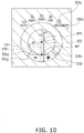
- the controller 52 expands the temperature change input detection area 58d as illustrated in FIG. 10 .
- the temperature change input detection area 58d which was substantially the same size as the temperature setting button 55d in the movement path 55e, is made larger than the movement path 55e.
- the expanded temperature change input detection area 58d is maintained in the expanded state as long as contact with the temperature change input detection area 58d continues.
- the controller 52 maintains the expanded temperature change input detection area 58d, such as that in FIG. 10 , as long as the temperature setting button 55d is being drag-operated.
- drag operation refers to an operation including touching a button on a screen of the display 551 compatible with drag operation, performing a swipe operation to move the button while touching the button, and then, releasing the touching of the screen. Accordingly, even if a button that is compatible only with touch operation (also referred to as “tap operation”), that is, a button that can detect being touched but cannot detect being moved, is touched and, while touched, is swiped to move the button, this operation is not a drag operation.
- a button compatible with drag operation is also referred to as a "drag button.”
- An area where the drag operation is possible is also referred to as a "drag area.”
- the temperature change input detection area 58d is expanded to the point of overlapping with the plus button 55f and the minus button 55g, the temperature raise input detection area 58f and the temperature lower input detection area 58g will no longer exist at the locations overlapping with the plus button 55f and the minus button 55g.
- tap operation of the plus button 55f or the minus button 55g will be ignored and the drag operation of the temperature setting button 55d will continue.
- the mode input detection areas 58c will no longer exist at the locations overlapping with the operation mode buttons 55c. Accordingly, even if a finger, for example, is slid to the location of the operation mode buttons 55c during a drag operation of the temperature setting button 55d, tap operation of the operation mode buttons 55c will be ignored and the drag operation of the temperature setting button 55d will continue.
- the controller 52 sets a reference point BP1 at the center of the circular arc-shaped movement path 55e. Furthermore, the management screen detection area determination unit 54d of the controller 52 sets a cancel area 60 on a line segment LS1 connecting the reference point BP1 to a midpoint MP of a line segment LS2 connecting the one end 59a of the movement path 55e to the other end 59b of the movement path 55e.
- the cancel area 60 is elongated along the line segment LS1.
- the cancel area 60 is configured such that a length in a direction along the line segment LS1 is greater than a width in an extending direction of the line segment LS2 (direction orthogonal to the line segment LS1).
- a length of a gap CL1 between the movement path 55e and the cancel area 60 is 30% of an inner diameter D1 of the movement path 55e. If the gap CL1 is too large, the effects of reducing settings of unintended values as the temperature setting value will be diminished, and if too small, normal change operations of the temperature setting value will be impeded. As such, the gap CL1 is set to a range of 20% to 40%, for example, of the inner diameter D1 of the movement path 55e. (6-2) Drag operation
- FIGS. 11A, 11B, and 11C Basic drag operations for the temperature setting button 55d are illustrated in FIGS. 11A, 11B, and 11C .
- the user touches the temperature setting button 55d with a finger 200 (see FIG. 11A ). While touching the temperature setting button 55d with the finger 200, the user moves the finger 200 along the movement path 55e. Note that, in FIG. 11B , the temperature setting button 55d illustrated by the dashed circle indicates the point where the movement of the finger 200 started.
- the management screen generation unit 54c sequentially generates screens so as to re-draw the temperature setting button 55d at the drag operation position that the finger 200 is contacting.
- the temperature setting button 55d Due to the temperature setting button 55d being re-drawn at the position where the finger 200 is contacting, to the user, the temperature setting button 55d appears to be being slid on the movement path 55e by the finger 200. While not illustrated in FIG. 11B , the management screen generation unit 54c displays a value of the set temperature corresponding to the position of the temperature setting button 55d, that is, corresponding to the drag operation position of the finger 200, in a region surrounded by the movement path 55e. Additionally, with a time when the finger 200 is lifted as a boundary, the temperature change input detection area 58d is shrunk from the expanded state illustrated in FIG. 10 to the normal state illustrated in FIG. 8 .
- the user lifts the finger 200 from the temperature setting button 55d at the location where the desired value of the set temperature is displayed (see FIG. 11C ).
- the value of the set temperature is confirmed as a result of the finger 200 being lifted from the temperature setting button 55d.
- the value of the set temperature is a value that corresponds to the position where the finger 200 was lifted from the temperature setting button 55d. For example, when the position where the finger 200 was lifted is the middle section 59c of the movement path 55e, the set temperature changes to 24° C.
- the drag operation position P1 is within the range of the temperature change input detection area 58d. Accordingly, even if the finger 200 stops at the drag operation position PI, the finger 200 is still touching the screen of the display 551 and, as such, the drag operation is being continued.
- the controller 52 connects the drag operation position P1 to the reference point BP1 using a straight line SS1. Then, the controller 52 regards the situation as if the temperature setting button 55d had been moved, by the finger 200, to a crossing point where the straight line SS1 crosses the movement path 55e. In other words, the controller 52 moves the drag button, namely the temperature setting button 55d, to a crossing point CP1 where the straight line connecting the drag operation position P1 and the reference point BP1 crosses the movement path 55e in the drag area, namely the temperature change input detection area 58, and changes the temperature setting value to a value corresponding to the position of the temperature setting button 55d.
- the change temperature setting value may be confirmed by simply lifting the finger 200 from the screen of the display 551 at the drag operation position P1. Additionally, the set temperature may be changed to a different value by continuing the swipe operation without lifting the finger 200 from the drag operation position P1.
- the value of the set temperature when the straight line SS1 extending from the reference point BP1 to the drag operation position P2 is drawn and the temperature setting button 55d is moved to the crossing point CP1 where the straight line SS1 crosses the movement path 55e, is the value when the finger 200 is at the drag operation position P2. Even when the drag operation position P2 is inside the movement path 55e, the value of the set temperature corresponding to the position of the temperature setting button 55d is confirmed when the finger 200 is lifted from the screen of the display 551 at the drag operation position P2.
- FIG. 13A illustrates a state in which the controller 52 has displayed the movement path 55e and the drag button, namely the temperature setting button 55d on the display 551 using the management screen generation unit 54c. Additionally, in the state illustrated in FIG.
- the temperature setting button 55d is touch-operated by the finger 200, and the controller 52 uses the management screen detection area determination unit 54d to provide the reference point BP1 disposed at a location off the movement path 55e, and set the drag area, namely the temperature change input detection area 58d, to be larger than the display range of the movement path 55e.
- the controller 52 also sets the cancel area 60 using the management screen detection area determination unit 54d.
- the position of the temperature setting button 55d illustrated in FIG. 13A corresponds to the value of the current set temperature.
- the finger 200 of the user traces a trajectory indicated by the arrow Ar3 so as to swipe to a drag operation position P3, deviating from the movement path 55e toward the side closer to the reference point BP1.
- the drag operation is in progress in the state illustrated in FIG. 13B but, as described previously, the temperature setting button 55d is moved to the crossing point where the straight line SS2 connecting the drag operation position P3 to the reference point BP1 crosses the movement path 55e.
- the value of the set temperature corresponding to the position of the temperature setting button 55d indicated by the dot-dot-dash line is a temperature that is significantly higher than the temperature that the user intended to set. If the user fails to check the set temperature in such a situation, the air conditioner 10a will maintain the actual room at a high temperature that the user does not intend.
- the cancel area 60 is set and, as such, the controller 52 determines that the drag operation was ended where the arrow Ar4 crosses the cancel area 60, or, in other words, makes a determination to regard the finger 200 as having been lifted from the screen of the display 551 at the location where the arrow Ar4 crosses the cancel area 60.
- the temperature setting button 55d will move very little due to the erroneous operations of the user, and values resulting from the erroneous operation of the user, significantly different from the value of the set temperature intended to be set by the user, can be reduced from being set as the set temperature.
- the mobile terminal 50 of the air conditioning system 100 namely the smartphone 500
- the setting value change device for changing the temperature setting value of the refrigeration apparatus.
- the value changed by the setting value change device according to the present invention is a hot water amount setting value of a hot water supply device, instead of the temperature setting value of the refrigeration apparatus. Changing of the hot water amount setting value of the hot water supply device is described using FIGS. 14 and 15 .
- a hot water supply system is configured to send and receive, using the smartphone 500, a portion or all of information such whether or not to supply hot water, whether or not to fill a bathtub with hot water, whether or not to reheat the water in the bathtub, a temperature setting of the hot water supply temperature, and a hot water amount setting of hot water stored in a hot water storage tank.
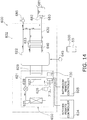
- FIG. 14 illustrates a configuration of a hot water supply system 600 according to Modification Example 1A.
- the hot water supply system 600 of FIG. 14 is installed in a residence, and includes a hot water supply device 602, a kitchen remote controller 604, and a bathroom remote controller 605.
- This hot water supply system 600 can supply heated water to a bathtub faucet 682 of a bathtub 681 installed in a bathroom of the residence, and to a water faucet 685 installed in a kitchen or the like.
- the hot water supply device 602 includes a heat pump unit 621, a hot water storage tank 622, and a second water heat exchanger 623.
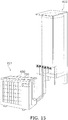
- FIG. 15 illustrates the appearance of the heat pump unit 621 and the hot water storage tank 622.
- the heat pump unit 621 includes an air heat exchanger 625, a compressor 626, a first water heat exchanger 627, and an expansion valve 628. These components are sequentially connected to form a refrigeration circuit.
- the heat pump unit 621 pumps up heat in the atmosphere in the air heat exchanger 625 and transfers the heat to a refrigerant.
- the refrigerant is compressed in the compressor 626, and the heat of the high-temperature refrigerant is transferred to water flowing through piping 629 in the first water heat exchanger 627.
- the refrigerant is decompressed and the temperature thereof is lowered at the expansion valve 628 and, then, the low-temperature refrigerant is sent to the air heat exchanger 625.
- Water is supplied into the hot water storage tank 622 from a water supply source 645.
- the water supplied into the hot water storage tank 622 is sent to the piping 629 and boiled in the first water heat exchanger 627.
- hot water is made.
- the (hot) water stored in the hot water storage tank 622 is supplied to the water faucet 685 and/or supplied to the bathtub 681.
- the water in the bathtub 681 is sent from a bathtub recovery port 683 of the bathtub 681 through a bathtub circulation path 630 to the second water heat exchanger 623, and thereafter returned back into the bathtub 681 through the bathtub faucet 682.
- the water in the hot water storage tank 622 is sent through a hot water storage tank circulation path 640 to the second water heat exchanger 623 and, thereafter returned back into the hot water storage tank 622.
- the water in the bathtub 681 is warmed up as a result of being subjected to heat exchange with the high-temperature water in the hot water storage tank 622 by the second water heat exchanger 623 (reheating operation).
- a control unit 713 made from a microcomputer configured from a CPU, ROM, and the like is installed in a main body casing 650 of the heat pump unit 621.
- the control unit 713 controls the various functional components in the heat pump unit 621, and also controls the boiling operations, bathtub filing operations, reheating operations, and the like on the basis of detection results of a water level sensor 715 and a temperature sensor 714 disposed in the hot water storage tank 622.
- the control unit 13 controls the operation of the hot water supply device 602, that is, controls the actions of the compressor 626, the expansion valve 628, and other components of the refrigeration circuit, in accordance with commands input, via the kitchen remote controller 604, the bathroom remote controller 605, and the smartphone 500, into the hot water supply device 602 by the user.
- control unit 713 outputs information related to the hot water supply device 602 to the kitchen remote controller 604 and the bathroom remote controller 605.
- information related to the hot water supply device 602 include information indicating whether or not the hot water supply device 602 is currently performing a variety of operations such as bathtub filling operations or reheating operations, information indicating the amount of hot water remaining in the hot water storage tank 622, and the current temperature and amount of hot water in the bathtub 681.
- the control unit 713 sends the device data 25a related to the hot water supply device 602 to an adapter 720. In one example, the control unit 713 sends, to the adapter 720, data indicating the content of a control command input into the hot water supply device 602 via the remote controllers 604 and 605.
- control unit 713 executes control commands sent from the adapter 720.
- the "control commands sent from the adapter 720" are, for example, operation commands for the hot water supply device 602 and/or commands ordering the sending of specific device data to the adapter 720.
- the storage unit 18 includes the possessed function information 18a, the cumulative operating time 18b, and the like.
- the cumulative operating time 18b is the cumulative operating time of the hot water supply device 602, as counted by the timer 17.
- the possessed function information 18a is information related to functions possessed by the hot water supply device 602.
- the possessed function information 18a is sent to the adapter 720 as a portion of the device data 25a, and is stored in the storage unit 24a of the adapter 720.
- control unit 713 sends the temperature data 25b and hot water amount data 25c to the adapter 720. Specifically, the control unit 713 sends, to the adapter 720, temperature data detected by the temperature sensor 714 and hot water amount data detected by the water level sensor 715.
- the kitchen remote controller 604 is installed on a wall of the kitchen of the residence of the user.
- the kitchen remote controller 604 is used to remotely control the hot water supply device 602, and is connected to the control unit 713 of the hot water supply device 602.
- functions of the kitchen remote controller 604 include setting functions such as whether or not to supply hot water, whether or not to fill the bathtub, whether or not to reheat the water in the bathtub, the hot water supply temperature, and the hot water amount setting value; and guidance functions for notifying that the bathtub filling operation has completed, the reheating operation has completed, the amount of hot water in the hot water storage tank 622 has changed, and the like.
- the bathroom remote controller 605 is used to remotely control the hot water supply device 602, and is installed on a wall in the bathroom of the residence.
- the bathroom remote controller 605 also has the setting functions and guidance functions described above.
- the adapter 720 is installed in an electrical component section 690.
- the adapter 720 is a network adapter for connecting the hot water supply device 602 to the LAN 81.
- the adapter 720 can be configured in the same manner as the adapters 20a and 20b described above.
- the adapter 720 has a control function for controlling the hot water supply device 602.
- the adapter 720 is connected by wire to the control unit 713 of the hot water supply device 602, and receives power from the hot water supply device 602 to operate (not illustrated in the drawings).
- the device data 25a, the temperature data 25b, the hot water amount data 25c, and the like are stored in the storage unit 24a. As described above, these pieces of data 25a, 25b, and 25c are pieces of data related to the hot water supply device 602 that are sent from the hot water supply device 602 to the adapter 720. Moreover, the adapter 720 periodically (every one minute in this case) compiles these pieces of data 25a, 25b, and 25c as information of the hot water supply device 602 and sends the compiled information to the server 40 depicted in FIG. 17 via the public line 80.
- a server address is stored in advance in the storage unit 24a.
- a device ID allocated to the adapter 720 by the server 40 is also stored in the storage unit 24a.
- the device ID which is an identification code of the adapter 720, is information whereby the server 40 uniquely identifies the adapter 720.
- the hot water supply system 600 is also provided with information mediation devices including the adapter 720, a router (not illustrated in the drawings), and the server 40.
- the information mediation devices of the hot water supply system 600 are also devices that use the public line 80 to exchange information between the hot water supply device 602 and the mobile terminal, namely the smartphone 500.
- the storage unit 43 of the server 40 has a database for accumulating various data related to the hot water supply device 602.
- the hot water amount data 25c related to the hot water amount is stored in the adapter-specific database 43a of the storage unit 43 corresponding to the adapter 720.
- the configuration of the smartphone 500 is the same as in the air conditioning system 100.
- a hot water supply management application 754 for managing the hot water supply device 602 by the smartphone 500 is installed on the smartphone 500.
- the user downloads the hot water supply management application 754 from the server 40 via the public line 80.
- the user can monitor information of the hot water supply device 602 and operate the hot water supply device 602 via images generated and provided to the touchscreen device 55 by the hot water supply management application 754.
- the hot water supply management application 754 possesses the internet address of the server 40, which is the connection destination, from the beginning.
- the hot water supply system 600 becomes usable by connecting the adapter 720 to the hot water supply device 602, causing the router 21 to recognize the adapter 720, the user downloading and installing the hot water supply management application 754 on the smartphone 500, and the user performing initial settings in the building 30, such as his own house.
- the initial settings of the hot water supply system 600 can be performed in the same manner as the air conditioning system 100 and, as such, a detailed description of the initial settings is omitted.
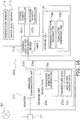
- the hot water supply management application 754 has a variety of functions and is provided with, as fundamental functional units, a hot water supply device information request unit 754a, a hot water supply device information acquisition unit 754b, a management screen generation unit 754c, and a management screen detection area determination unit 754d.
- the data related to the hot water supply device 602 is received by the hot water supply device information acquisition unit 754b of the hot water supply management application 754 and is temporarily stored in the memory of the smartphone 500.
- the management screen generation unit 754c of the hot water supply management application 754 generates, on the basis of the possessed function information 18a and other data related to the hot water supply device 602, a hot water supply device management screen for monitoring and operating, which is displayed on the touchscreen device 55.
- the management screen detection area determination unit 754d of the hot water supply management application 754 determines, on the basis of the possessed function information 18a and other data related to the hot water supply device 602, detection areas in which contact with the screen of the touchscreen device 55 is to be detected and which correspond to the hot water supply device management screen.
- the hot water supply device information request unit 754a issues a request, via the second wireless communication unit 51b, to the adapter 720 for the information of the hot water supply device 602 connected to the adapter 720.
- the adapter 720 Upon receipt of this information transmission request, the adapter 720 sends the variety of data related to the hot water supply device 602 stored in the storage unit 24a to the smartphone 500.
- This variety of data related to the hot water supply device 602 includes the device data 25a including the possessed function information 18a, the temperature data 25b such as the set temperature, the hot water amount data 25c, and the like.
- the subsequent generation and operation of the hot water supply device management screen are the same as the actions of the air conditioning management application 54 of the smartphone 500.
- the control unit 713 of the hot water supply device 602 uses the management screen generation unit 754c to cause the display 551 to display a plus button 755f for raising the hot water amount setting, a minus button 755g for lowering the hot water amount setting, a drag-type hot water amount setting button 755d capable of continuously changing the hot water amount setting, and an elliptical-shaped movement path 755e on which the hot water amount setting button 755d moves.
- the management screen detection area determination unit 754d of the control unit 713 provides a reference point BP2 disposed at a location off the movement path 755e and a hot water amount change input detection area 758d for detecting a drag input on the hot water amount setting button 755d, which is a drag button.
- the reference point BP2 is provided at a midpoint of a line segment connecting the two center points of the elliptical arcs.
- the management screen detection area determination unit 754d of the controller 52 sets a cancel area 760 on a line segment LS3 connecting the reference point BP2 to a midpoint MP of a line segment LS4 connecting a one end 759a of the movement path 755e to the other end 759b of the movement path 755e.
- the cancel area 760 is elongated along the line segment LS3.
- the cancel area 760 is configured such that a length in a direction along the line segment LS3 is greater than a width in an extending direction of the line segment LS4.
- the controller 52 expands the hot water amount change input detection area 758d as illustrated in FIG. 19 .
- sections other than the cancel area 760 are the hot water amount change input detection area 758d.
- the controller 52 connects a drag operation position P5 to the reference point BP2 by a preset specific curve CC1 such as that illustrated in FIG. 19 .
- the controller 52 performs change processing to move the hot water amount setting button 755d to a crossing point where the specific curve CC1 crosses the movement path 755e, and change the hot water amount setting value to a value corresponding to the position of the hot water amount setting button 755d.
- the smartphone 500 or similar mobile terminal 50 is the setting value change device.
- the setting value change device is not limited to mobile terminals and, for example, the present invention can be used in a configuration in which the remote controller 15, 604, and/or 605 is provided with a touchscreen device and the remote controller 15, 604, and/or 605 is used as the setting value change device.
- the movement path 55e or 755e is circular arc-shaped or elliptical arc-shaped.
- shape of the movement path is not limited to the shapes described in the embodiment or modification examples described above.
- the refrigeration apparatuses are the air conditioners 10 and 10a, and the air conditioners 10 and 10a are also capable of heating.
- the present invention is not limited to use in heating apparatuses provided with refrigeration circuits for performing refrigeration cycles, and may also be used in heating apparatuses without refrigeration circuits.
- Examples of heating apparatuses without refrigeration circuits for performing refrigeration cycles include heating apparatuses that directly convert electricity and/or fuel to heat, and examples of such heating apparatuses that directly convert electricity and/or fuel to heat include central heating systems that use electricity and/or fuel to heat water and/or air, and circulate that heated water or air to heat a floor or wall.
- the controller 52 of the setting value change device namely the smartphone 500 (or the mobile terminal 50) sets the temperature change input detection area 58d to be larger than the display range of the movement path 55e.
- the air conditioning system 100 includes the air conditioners 10a and 10b as the refrigeration apparatuses.
- the controller 52 of the smartphone 500 sets the hot water amount change input detection area 758d to be larger than the display range of the movement path 755e.
- the hot water supply system 600 includes the hot water supply device 602.
- the controller 52 performs change processing to move the temperature setting button 55d to the crossing point where the straight line SS1 or SS2 connecting the drag operation position P1 or P2 to the reference point BP1 or BP2 crosses the movement path 55e in the temperature change input detection area 58d, and change the temperature setting value to the value corresponding to the position of the temperature setting button 55d where the finger 200 was lifted.
- the controller 52 performs change processing to move the hot water amount setting button 755d to the crossing point where the specific curve CC1 connecting the drag operation position P4 to the reference point BP2 crosses the movement path 755e in the hot water amount change input detection area 758d, and change the hot water amount setting value to the value corresponding to the position of the hot water amount setting button 755d where the finger 200 was lifted.
- a configuration is described in which, when the temperature setting button 55d is being dragged, the temperature change input detection area 58d is expanded to the range where the operation buttons, namely the operation mode buttons 55c, the plus button 55f, the minus button 55g, and the like are displayed and, for example, even if there is a touch operation on the operation mode buttons 55c, the plus button 55f, or the minus button 55g, the change operation of the temperature setting value will be continued.
- the temperature change input detection area 58d can be expanded even when setting, for example, the operation mode buttons 55c, the plus button 55f, and the minus button 55g, and erroneous inputs can be reduced because mode switching and the like will not occur even if the operation mode buttons 55c, the plus button 55f, or the minus button 55g is touch-operated during the drag operation of the temperature setting button 55d.
- drag operations are easier to perform and, also, correct change operations of temperature setting values are easier.
- the hot water amount change input detection area 758d is expanded to the range where the operation buttons, namely the plus button 755f, the minus button 755g, and the like are displayed and, for example, even if there is a touch operation on the plus button 755f or the minus button 755g, the change operation of the hot water amount setting value will be continued.
- the hot water amount change input detection area 758d can be expanded even when setting, for example, the plus button 755f and the minus button 755g, and erroneous inputs can be reduced because changes of the hot water amount and the like will not occur even if the plus button 755f or the minus button 755g is touch-operated during the drag operation of the hot water amount setting button 755d.
- drag operations are easier to perform and, also, correct change operations of hot water amount setting values are easier.
- the cancel area 60 or 760 is provided so as to cross the straight line connecting the one end 59a or 759a to the other end 59b or 759b, and this configuration results in a high probability of reducing misoperations such as changing to a value near the lower limit value when intending to change to a value near the upper limit value and changing to a value near the upper limit value when intending to change to a value near the lower limit value.
- the cancel area 60 or 760 is disposed in the range including the line segment LS1 or LS3 connecting the middle of the one end 59a or 759a of the movement path 55e or 755e to the other end 59b or 759b of the movement path 55e or 755e, namely the midpoint MP to the reference point BP1 or BP2.
- the shape of the cancel area 60 or 760 is set such that the length in the direction along the line segment LS1 or LS3 is longer than the length in the direction connecting the one end 59a or 759a to the other end 59b or 759b. As such, it is possible to reduce misoperations in which, during a drag operation, the cancel area 60 or 760 is unintentionally touched when intending to set to a value near the lower limit value or to a value near the upper limit value. As a result, it is possible to reduce misoperations such as an unintentional input of a value near the upper limit value and an unintentional input of a value near the lower limit value.
- the cancel area 60 or 760 has a shape in which the length in the direction along the line segment LS1 or LS3 is equal to the length in the direction connecting the one end 59a or 759a to the other end 59b or 759b, if a swipe operation is performed even slightly deviating from the movement path 55e or 755e, the cancel area will be touched and the drag operation will be ended.
- the temperature change input detection area 58d or the hot water amount change input detection area 758d is expanded to set the drag area larger than the display range of the movement path.
- the operation buttons such as the plus button 55f or 755f and the minus button 55g or 755g in the temperature change input detection area 58d or the hot water amount change input detection area 758d of the expanded portion before and after the performance of the drag operation, thereby making the performance of operations other than drag operations easier.
- the overall operability of the touchscreen device 55 can be enhanced.
Landscapes
- Engineering & Computer Science (AREA)
- General Engineering & Computer Science (AREA)
- Physics & Mathematics (AREA)
- Theoretical Computer Science (AREA)
- Combustion & Propulsion (AREA)
- Mechanical Engineering (AREA)
- Chemical & Material Sciences (AREA)
- Thermal Sciences (AREA)
- General Physics & Mathematics (AREA)
- Human Computer Interaction (AREA)
- Air Conditioning Control Device (AREA)
- Central Heating Systems (AREA)
- Heat-Pump Type And Storage Water Heaters (AREA)
- User Interface Of Digital Computer (AREA)
- Measuring Pulse, Heart Rate, Blood Pressure Or Blood Flow (AREA)
- Paper (AREA)
- Stabilization Of Oscillater, Synchronisation, Frequency Synthesizers (AREA)
Abstract
Description
- The present invention relates to a setting value change device for changing a desired temperature of a refrigeration apparatus and/or a heating apparatus or a desired hot water amount of a hot water supply device.
- In the related art, there are setting value change devices for changing desired temperature s of refrigeration apparatuses such as heat pump systems or desired hot water amounts of hot water supply devices. Examples thereof include a remote control device of a heat pump system, and smartphones and tablet computers that connect to the heat pump system via communication means described in Patent Document 1 (Japanese Unexamined Patent Application Publication No.
2015-114057 Patent Document 1, the set temperature is changed mainly using tap input or toggle input, in which touch keys are pressed. However, when using tap input or toggle input, the change in the set temperature must be recognized as a numerical value and it is difficult to intuitively ascertain increases and decreases from bodily movement. As such, as described in Patent Document 2 (Japanese Unexamined Patent Application Publication (Translation ofPCT Application) No. 2015-513747 - However, with methods utilizing touch operation in which the dragged drag button never deviates from the position touched by the finger, a user must carefully trace the movable path of the drag button. Consequently, input is burdensome. Moreover, erroneous input occurs in cases where the finger of the user traces a trajectory deviating from the movable path.
- An object of the present invention is to provide a setting value change device that facilitates change operations to correct temperature setting values or hot water amount setting values by drag operations.
- A setting value change device according to a first aspect of the present invention performs change processing to change a temperature setting value of a refrigeration apparatus and/or a heating apparatus. The setting value change device includes a display that displays the temperature setting value; a touch sensor that detects a touch operation on the display, the touch sensor arranged and configured to transmit a display on the display; and a controller connected to the display and the touch sensor. The controller performs change processing to cause the display to display a drag button and a movement path on which the drag button moves; provide, on the touch sensor, a drag area that detects a drag input on the drag button and a reference point disposed at a location off the movement path; set the drag area larger than a display range of the movement path; and move the drag button to a crossing point where a straight line or a specific curve connecting the reference point to a drag operation position in the drag area crosses the movement path, and change the temperature setting value to a value corresponding to a position of the drag button.
- With the setting value change device of the first aspect, the controller performs change processing to set the drag area larger than the display range of the movement path, move the drag button to the crossing point where the straight line or specific curve connecting the reference point to the drag operation position in the drag area crosses the movement path, and change the temperature setting value to the value corresponding to the position of the drag button. As such, even when a user performs rough operations resulting in the drag operation position deviating from the movement path, the drag operation can be continued and the drag button can be moved along the movement path.
- A setting value change device according to a second aspect of the present invention is the setting value change device according to the first aspect, wherein the controller causes the display to display an operation button near the movement path; performs settings to enable the touch sensor to detect and input a touch operation on the operation button; and, when the drag button is being dragged, expands the drag area up to a range in which the operation button is displayed so that a change operation of the temperature setting value is continued even if there is a touch operation on the operation button.
- With the setting value change device of the second aspect, when the drag button is being dragged, the drag area is expanded up to the range in which the operation button is displayed so that the change operation of the temperature setting value is continued even if there is a touch operation on the operation button. As such, a wide drag area can be obtained even when the operation button is set, and erroneous input caused by touch operations of the operation button can be reduced. As a result, drag operations are facilitated and it is easier to perform correct change operations of the temperature setting value.
- A setting value change device according to a third aspect of the present invention is the setting value change device according to the first or second aspect, wherein the controller sets a cancel area such that the cancel area is touched at a time of the drag operation of the drag button, the change processing of the temperature setting value is not continued.
- With the setting value change device of the third aspect, the change processing of the temperature setting value is not continued when the cancel area is touched during the drag operation of the drag button, and the temperature setting is completed at the timing. As such, changes to unintended temperature setting values resulting from drag operations to points beyond the end of the cancel area are eliminated.
- A setting value change device according to a fourth aspect of the present invention is the setting value change device according to the third aspect, wherein the controller causes the display to display the movement path as a non-linear shape; associates a value from when a position of the drag button is at a one end of the movement path with a lower limit value of the temperature setting value; associates a value from when the position of the drag button is at the other end of the movement path with an upper limit value of the temperature setting value; and sets the cancel area to a range connecting a periphery of the one end of the movement path to a periphery of the other end of the movement path.
- With the setting value change device of the fourth aspect, the cancel area is set to the range connecting the periphery of the one end of the movement path to the periphery of the other end of the movement path. As such, a misoperation in which a value near the lower limit value is inputted due to a finger moving to a location for inputting a value near the lower limit value can be reduced when the input is ended intending to input a value near the upper limit value and, also, a misoperation in which a value near the upper limit value is inputted due to a finger moving to a location for inputting a value near the upper limit value can be reduced when the input is ended intending to input a value near the lower limit value.
- A setting value change device according to a fifth aspect of the present invention is the setting value change device according to the fourth aspect, wherein the controller disposes the cancel area so as to cross the straight line connecting the one end of the movement path to the other end of the movement path.
- With the setting value change device of the fifth aspect, when there is a significant difference between the desired temperature and the actual set temperature, there is a high probability of the drag operation being incorrectly performed on or near the straight line connecting the one end of the movement path to the other end of the movement path. As such, the cancel area is provided so as to cross the straight line connecting the one end to the other end, and this configuration results in a high probability of reducing misoperations such as changing to a value near the lower limit value when intending to change to a value near the upper limit value and changing to a value near the upper limit value when intending to change to a value near the lower limit value.
- A setting value change device according to a sixth aspect of the present invention is the setting value change device according to the fourth or fifth aspect, wherein the controller causes the display to display the movement path as a circular arc shape or an elliptical arc shape; and disposes the cancel area at a position surrounded by the movement path.
- With the setting value change device of the sixth aspect, when moving the drag button along the movement path that is formed in the circular arc shape or the elliptical arc shape, there are cases where the drag operation is ended while moving the drag operation position toward the inside of the arc. The cancel area is disposed at the position surrounded by the movement path. As a result, misoperations such as changing to a value near the lower limit value when intending to change to a value near the upper limit value and changing to value near the upper limit value when intending to change to a value near the lower limit value can be reduced by the cancel area that is disposed at the position inside the arc surrounded by the circular arc-shaped or elliptical arc-shaped movement path.
- A setting value change device according to a seventh aspect of the present invention is the setting value change device according to any one of the fourth to sixth aspects, wherein the controller disposes the cancel area in a range including a line segment connecting the middle of the one end of the movement path and the other end of the movement path to the reference point.
- With the setting value change device of the seventh aspect, the cancel area is disposed in the range including the line segment connecting the middle of the one end of the movement path and the other end of the movement path to the reference point. As such, drag input resulting from a drag operation traversing the line segment can be reduced, and misoperations such as changing to the lower limit value when intending to change to the upper limit value and changing to the upper limit value when intending to change to the lower limit value can be reduced by the cancel area that is disposed on the line segment.
- A setting value change device according to an eighth aspect of the present invention is the setting value change device according to the seventh aspect, wherein the controller sets a shape of the cancel area such that a length in a direction along the line segment is longer than a length in a direction connecting the one end to the other end.
- With the setting value change device of the eighth aspect, the shape of the cancel area is set such that the length in the direction along the line segment is longer than the length in the direction connecting the one end to the other end. As such, it is possible to reduce misoperations in which, during a drag operation, the cancel area is unintentionally touched when intending to set to a value near the lower limit value or to a value near the upper limit value and the setting is not successfully completed.
- A setting value change device according to a ninth aspect of the present invention is the setting value change device according to any one of the first to eighth aspects wherein, prior to the drag button being touched, the controller sets the drag area to a range smaller than the display range of the movement path including the display range of the drag button; and, after the drag operation of the drag button has started, the controller expands the drag area to set the drag area larger than the display range of the movement path.
- With the setting value change device of the ninth aspect, after the drag operation of the drag button has started, the controller expands the drag area to set the drag area larger than the display range of the movement path. As such, it is possible the dispose the operation button, for example, in the drag area of the expanded portion before and after the performance of the drag operation, thereby making the performance of operations other than the drag operation easier.
- A setting value change device according to a tenth aspect of the present invention performs change processing to change a hot water amount setting value of a hot water supply device. The setting value change device includes a display that displays the hot water amount setting value; a touch sensor that detects a touch operation on the display, the touch sensor arranged and configured to transmit a display on the display; and a controller connected to the display and the touch sensor. The controller performs change processing to cause the display to display a drag button and a movement path on which the drag button moves; provide a drag area that detects a drag input on the drag button and a reference point disposed at a location off the movement path; set the drag area larger than the display range of the movement path; and move the drag button to a crossing point where a straight line or a specific curve connecting the reference point to a drag operation position in the drag area crosses the movement path, and change the hot water amount setting value to a value corresponding to a position of the drag button.
- With the setting value change device of the tenth aspect, the controller performs change processing to set the drag area larger than the display range of the movement path, move the drag button to the crossing point where the straight line or specific curve connecting the reference point to the drag operation position in the drag area crosses the movement path, and change the hot water amount setting value to the value corresponding to the position of the drag button. As such, even when a user performs rough operations resulting in the drag operation position deviating from the movement path, the drag operation can be continued and the drag button can be moved along the movement path and it is easier to perform change operations to correct hot water amount setting value.
- With the setting value change device according to the first aspect of the present invention, change operations to correct temperature setting values by drag operation are facilitated.
- With the setting value change device according to the second aspect, drag operations are easier to perform and, also, correct change operations to temperature setting values are facilitated.
- With the setting value change device according to the third aspect, changes to unintended temperature setting values are reduced and, as a result, the risk of causing a user discomfort is mitigated.
- With the setting value change device according to the fourth aspect, it is possible to mitigate the risk of a significant temperature difference occurring between the set temperature and the temperature intended to be set due to mistakenly inputting a value near the lower limit value instead of a value near the upper limit value of the temperature setting value, or mistakenly inputting a value near the upper limit value instead of a value near the lower limit value of the temperature setting value.
- With the setting value change device according to the fifth aspect, the feature for reducing the significant temperature difference from occurring between the set temperature and the temperature intended to be set is enhanced.
- With the setting value change device according to the sixth aspect, when the movement path is the circular arc shape or the elliptical arc shape, the feature for reducing the significant temperature difference from occurring between the set temperature and the temperature intended to be set is significantly enhanced.
- With the setting value change device according to the seventh aspect, the feature for reducing a significant temperature difference from occurring between the set temperature and the temperature intended to be set is significantly enhanced.
- With the setting value change device according to the eighth aspect, it is possible to reduce misoperations such as the unintentional input of a value near the upper limit value and the unintentional input of a value near the lower limit value.
- With the setting value change device according to the ninth aspect, operability can be enhanced.
- With the setting value change device according to the tenth aspect, change operations to correct hot water amount setting values by touch operation are facilitated.
-
-
FIG. 1 is a conceptual diagram illustrating a schematic configuration of an air conditioning system according to an embodiment of the present invention; -
FIG. 2 is a block diagram that explains the configurations of a control unit and an adapter of an air conditioner; -
FIG. 3 is a block diagram that explains the configurations of a server and a controller of a smartphone; -
FIG. 4 is a drawing illustrating the content of possessed function information of the air conditioner; -
FIG. 5 is a drawing illustrating the content of data stored in an adapter-specific database on the server; -
FIG. 6A is a drawing illustrating a list screen of air conditioners displayed on a touchscreen device of the smartphone when performing initial settings; -
FIG. 6B is a drawing illustrating a setting screen for an air conditioner displayed on the touchscreen device of the smartphone when performing initial settings; -
FIG. 7 is a drawing illustrating an example of an air conditioner management screen of an air conditioner selected by a user; -
FIG. 8 is a drawing that explains the setting of detection areas for the air conditioner management screen ofFIG. 7 ; -
FIG. 9A is a drawing that explains a screen related to the lower limit value of the set temperature; -
FIG. 9B is a drawing that explains a screen related to the median of the set temperatures; -
FIG. 9C is a drawing that explains a screen related to the upper limit value of the set temperature; -
FIG. 10 is a drawing that explains the setting of a temperature change input detection area and a cancel area; -
FIG. 11A is a drawing that explains a touch operation on a temperature setting button; -
FIG. 11B is a drawing that explains a swipe operation on the temperature setting button; -
FIG. 11C is a drawing that explains an operation for confirming the value of the set temperature; -
FIG. 12 is a drawing that explains the changing of the value of the set temperature when a swipe operation is performed that deviates from a movement path; -
FIG. 13A is a drawing that explains a touch operation on the temperature setting button; -
FIG. 13B is a drawing that explains a swipe operation on the temperature setting button; -
FIG. 13C is a drawing that explains an operation for confirming the value of the set temperature by the cancel area; -
FIG. 14 is a circuit diagram of a hot water supply system according to a modification example; -
FIG. 15 is a perspective view illustrating a hot water supply device of the hot water supply system ofFIG. 14 ; -
FIG. 16 is a block diagram that explains the configurations of a control unit and an adapter of the hot water supply device; -
FIG. 17 is a block diagram that explains the configurations of a server and a controller of the smartphone; -
FIG. 18 is a drawing that explains a hot water supply device management screen for the hot water supply device; and -
FIG. 19 is a drawing that explains the setting of a detection area on the hot water supply device management screen. - Hereinafter, a description is given of a case in which a mobile terminal, specifically a smartphone, is used as an example of a setting value change device. As illustrated in
FIG. 1 , anair conditioning system 100 according to an embodiment of the present invention includes amobile terminal 50. As illustrated inFIG. 3 , themobile terminal 50 specifically is asmartphone 500. -
FIG. 1 illustrates the overall configuration of theair conditioning system 100. Theair conditioning system 100 is a system for acquiring information of desiredair conditioners mobile terminal 50 possessed by a user and operating the desiredair conditioners server 40 andadapters - A
router 21 is installed in abuilding 30. Therouter 21 connects a local area network (hereinafter referred to as a "LAN") 81 installed in thebuilding 30 to apublic line 80 including the Internet. The LAN 81 is a wireless LAN that uses the functions of therouter 21. Theadapters air conditioners adapters building 30 may also be connected to the LAN 81. - In order to manage the
air conditioners server 40 using themobile terminal 50, each of theair conditioners server 40. To facilitate comprehension, only onebuilding 30 is illustrated inFIG. 1 . However, an actualair conditioning system 100 includes theair conditioners buildings 30. Specifically, theserver 40 installed remotely from thebuilding 30 is operated, via thepublic line 80, by a manufacturer, sales company, or maintenance company of air conditioners, and information of the air conditioners inmultiple buildings 30 is accumulated in theserver 40. Note that the twoair conditioners adapters building 30, and configurations are possible in which one air conditioner or three or more air conditioners are provided and/or one adapter or three or more adapters are provided. - As illustrated in
FIG. 1 , theair conditioners indoor units outdoor units indoor units rooms 30a and 30b of thebuilding 30. Theoutdoor units building 30. In addition, theindoor units adapters air conditioner 10a and theair conditioner 10b have the same fundamental configuration and, as such, theair conditioner 10a is used as an example in the following description. - The
indoor unit 11a and theoutdoor unit 12a are connected to each other via a refrigerant pipe, which forms part of a refrigeration circuit that includes a compressor, a heat exchanger, and the like (not illustrated in the drawings). As illustrated inFIG. 2 , theair conditioner 10a has a variety of sensors. In one example, theindoor unit 11a has anindoor temperature sensor 14a that detects the temperature of theroom 30a in which theindoor unit 11a is installed. Meanwhile, theoutdoor unit 12a has an outsideair temperature sensor 14b that detects the temperature of outside air near thebuilding 30. - Additionally, the
air conditioner 10a has acontrol unit 13. Thecontrol unit 13 includes control units of theindoor unit 11a and theoutdoor unit 12a of theair conditioner 10a. Thecontrol unit 13 controls the operation of theair conditioner 10a, that is, controls the actions of the compressor and other components of the refrigeration circuit, in accordance with operation commands input, via aremote controller 15, into theair conditioner 10a by a user in theroom 30a. - Additionally, the
control unit 13 sendsdevice data 25a related to theair conditioner 10a to theadapter 20a. In one example, thecontrol unit 13 sends, to theadapter 20a, data indicating the content of a control command for theindoor unit 11a, input via theremote controller 15. The "data indicating the content of an operation command" is an operation start/operation stop, operation mode (cooling mode, heating mode, blowing mode, and the like), set temperature, and the like of theair conditioner 10a. Thedevice data 25a sent to theadapter 20a includes possessedfunction information 18a (described later),cumulative operating time 18b,power consumption 18c, and the like. - Additionally, the
control unit 13 sends, to theadapter 20a,temperature data 25b related to the indoor temperature and the outside air temperature. Specifically, thecontrol unit 13 sends, to theadapter 20a, room temperature data detected by theindoor temperature sensor 14a and outside air temperature data detected by the outsideair temperature sensor 14b. - Moreover, the
control unit 13 executes control commands sent from theadapter 20a. The "control commands sent from theadapter 20a" includes commands ordering the sending of operation commands for theindoor unit 11a and/or specific device data to theadapter 20a. - The
control unit 13 is provided with a CPU and astorage unit 18 including RAM and ROM. In thestorage unit 18, thepossessed function information 18a is stored in the ROM, and thecumulative operating time 18b, thepower consumption 18c, and the like are stored in the RAM Thecumulative operating time 18b is the cumulative operating time of theair conditioner 10a, as counted by atimer 17. Thepower consumption 18c is the power consumed by theair conditioner 10a, as measured by apower meter 14d. - The
possessed function information 18a is information related to functions possessed by theair conditioner 10a. As illustrated inFIG. 4 , thepossessed function information 18a is information that distinguishes between functions actually possessed and functions not possessed by theair conditioner 10a of a plurality of functions with which an air conditioner can be provided. In theair conditioning system 100, thepossessed function information 18a includes first information (code XX1 inFIG. 4 ), second information (code XX2 inFIG. 4 ), third information (code XX3 inFIG. 4 ), fourth information (code XX4 inFIG. 4 ), and fifth information (code XXX inFIG. 4 ). In one example, the first information is information of whether theair conditioner 10a has a time measurement function to measure the cumulative operating time. According to thepossessed function information 18a illustrated inFIG. 4 , it is clear that theair conditioner 10a is not provided with a function to perform laundry drying operations, a function to change wind direction by remote control, or a person detection function, and is provided with the function to measure cumulative operating time and a function to measure power consumption. As described above, thepossessed function information 18a is sent to theadapter 20a as a portion of thedevice data 25a, and is stored in astorage unit 24a of theadapter 20a. - The information mediation devices are devices that use the
public line 80 to enable exchange of information between theair conditioners mobile terminal 50. In theair conditioning system 100, the information mediation devices include theadapters router 21, and theserver 40. - The
adapters air conditioners adapter 20a and theadapter 20b have the same fundamental configuration and, as such, theadapter 20a is used as an example in the following description. - As illustrated in
FIG. 2 , theadapter 20a includes a CPU, awireless communication unit 22a, and astorage unit 24a. Theadapter 20a has a communication function to eliminate phase differences in communication protocols between networks and also a control function to control theair conditioners adapter 20a is connected by wire to thecontrol unit 13 of theindoor unit 11a, and receives power from theindoor unit 11a to operate (not illustrated in the drawings). - The
device data 25a, thetemperature data 25b, and the like are stored in thestorage unit 24a. As described above, these pieces ofdata air conditioner 10a that are sent from theair conditioner 10a to theadapter 20a. Moreover, theadapter 20a periodically (every one minute in this case) compiles these pieces ofdata air conditioner 10a and sends the compiled information to theserver 40 via thepublic line 80. - A server address is stored in advance in the
storage unit 24a. A device ID allocated to theadapter 20a by theserver 40 is also stored in thestorage unit 24a. The device ID, which is an identification code of theadapter 20a, is information whereby theserver 40 uniquely identifies theadapter 20a. - The
router 21 is a communication device that has a WAN side interface and a LAN side interface and that connects these two networks to each other. Therouter 21 automatically detects the presence of theadapters adapters adapters adapters air conditioning system 100, therouter 21 fulfills the role of constructing the LAN 81 in thebuilding 30. - The
server 40 is a computer that is provided on the public line 80 (on the Internet) to perform air conditioning management services, and that runs server software. As illustrated inFIG. 3 , theserver 40 has astorage unit 43. - The
storage unit 43 has a database for accumulating a variety of data related to theair conditioners storage unit 43 has an adapter-specific database 43a. Theserver 40 accumulates, by adapter, thedevice data 25a, thetemperature data 25b and the like of the air conditioner. Thedevice data 25a, thetemperature data 25b and the like are sent periodically from theadapter 20a. As illustrated inFIG. 5 , the variety of data related to theair conditioners specific database 43a in a manner associated with the device IDs allocated to theadapters air conditioners - Note that, in the adapter-
specific database 43a, information of an air conditioner to which one adapter is connected is stored together with information of an air conditioner to which a related adapter, which is different from the previously mentioned adapter, is connected as one record. For example, as described later, when there are twoadapters mobile terminal 50, theserver 40 identifies both of theadapters - A variety of setting information by the user of the
air conditioners specific database 43a. The device IDs of theadapters air conditioners air conditioners possessed function information 18a related to the functions possessed by theair conditioners air conditioners air conditioners air conditioners specific database 43a. The password is for authenticating login rights when the user uses the login ID to login to theserver 40 via thepublic line 80. - The
server 40 sends, via thepublic line 80, the variety of data stored in the adapter-specific database 43a to themobile terminal 50 of the user in response to a request from themobile terminal 50 of the user executing an airconditioning management application 54. - Additionally, the
server 40 sends an operation command, for operating theair conditioners mobile terminal 50 via thepublic line 80, to theadapters adapters - The
mobile terminal 50 is a terminal carried by the user of theair conditioners smartphone 500 is used as themobile terminal 50. - As illustrated in
FIG. 3 , thesmartphone 500 is provided with acontroller 52 including a CPU, a firstwireless communication unit 51a, a secondwireless communication unit 51b, astorage unit 53, and the like, and atouchscreen device 55 responsible for input and output functions. The firstwireless communication unit 51a has a function for connecting to thepublic line 80. The secondwireless communication unit 51b wirelessly communicates via Wi-Fi (registered trademark) and, as such, fulfills a role of connecting to theadapters building 30, without passing through thepublic line 80. Thetouchscreen device 55 functions as a display screen and also fulfills a role as operation buttons. The operation buttons are buttons included in images displayed on the display screen. - The air
conditioning management application 54 for managing theair conditioners smartphone 500 is installed on thesmartphone 500. The user downloads the airconditioning management application 54 from theserver 40 via thepublic line 80. The user can monitor information of theair conditioners air conditioners conditioning management application 54 and provided to thetouchscreen device 55. The airconditioning management application 54 possesses the internet address of theserver 40, which is the connection destination, from the beginning. - The
air conditioning system 100 becomes usable by connecting theadapters air conditioners router 21 to recognize theadapters conditioning management application 54 on thesmartphone 500 as described above, and the user performing initial settings in thebuilding 30 such as a residence. - Upon connection of the
adapters air conditioners adapters air conditioners device data 25a and thetemperature data 25b, and store the acquired information in thestorage unit 24a. Next, using the function of wireless connection settings of theadapters router 21 to recognize theadapters adapters - Then, in the
building 30, the user starts the airconditioning management application 54 installed on thesmartphone 500. Then, thesmartphone 500 running the air conditioning management application 54 (hereinafter referred to simply as "airconditioning management application 54") searches, via the secondwireless communication unit 51b and therouter 21, for theadapters FIG. 6A , displays a list thereof on thetouchscreen device 55. - When the user taps an icon of a device labeled "Not Configured 1" and presses an
edit button 56a, a subsequent screen (seeFIG. 6B ) is displayed for inputting a device name and an installation location, and performing other settings. In one example, when "Living" is input as the device name for theair conditioner 10a, from the next time, "Living" will be displayed instead of "Not Configured 1" on the list screen of air conditioners. - Upon selecting "External Operation Settings" illustrated in
FIG. 6B and changing the setting thereof form "OFF" to "ON", the airconditioning management application 54 will prompt the user to perform initial settings for operating that air conditioner from outside thebuilding 30. In this case, the user sets a login ID and a password. In cases where the airconditioning management application 54 recognizes the presence of two or more of theadapters adapters adapters air conditioners - When the login ID and the password are set, the
adapters server 40 via therouter 21. At this time, theadapters server 40. When theserver 40 is accessed by theadapters server 40 assigns device IDs to theadapters specific database 43a based on those IDs. Upon receipt of the device IDs from theserver 40, theadapters storage unit 24a. Next, in response to requests from theserver 40, theadapters air conditioners function information 18a, which is in thestorage unit 24a, to theserver 40. Theserver 40 enters the information of theair conditioners adapters specific database 43a of thestorage unit 43, associated with the device IDs of theadapters server 40 from outside for the first time using thesmartphone 500, the login ID, and the password, theserver 40 issues a request to theadapters air conditioners - Note that each record by device ID in the adapter-
specific database 43a is also associated with the login ID and the password determined by the user in the airconditioning management application 54 in which theadapters adapters specific database 43a of theserver 40, as illustrated inFIG. 5 . - After the initial settings, when the user starts the air
conditioning management application 54 using thesmartphone 500, an initial screen including input fields for the login ID and the password is displayed on thetouchscreen device 55 of thesmartphone 500. At this time, if the user does not input the provided login ID and the set password in the login ID and password input fields of the initial screen, the user cannot use the airconditioning management application 54 to view the information of theair conditioners storage unit 43 of theserver 40 or operate theair conditioners 10a and 10b.Thus, the possibility of remote control without authorization is reduced in theair conditioning system 100. - The air
conditioning management application 54 has a variety of functions and is provided with, as fundamental functional units, an air conditionerinformation request unit 54a, an air conditionerinformation acquisition unit 54b, a managementscreen generation unit 54c, and a management screen detectionarea determination unit 54d. - When, outside the
building 30, the airconditioning management application 54 on thesmartphone 500 is started and the user inputs the login ID and the password, the air conditionerinformation request unit 54a issues a request to theserver 40, via the firstwireless communication unit 51a, for the information of theair conditioners adapters server 40 sends, to thesmartphone 500, the variety of data related to theair conditioners adapters specific database 43a. This variety of data related to theair conditioners device data 25a including the possessedfunction information 18a, thetemperature data 25b such as the set temperature, and the like. - The data related to the
air conditioners information acquisition unit 54b of the airconditioning management application 54 and is temporarily stored in the memory of thesmartphone 500. The managementscreen generation unit 54c of the airconditioning management application 54 generates, on the basis of thepossessed function information 18a and other data related to theair conditioners touchscreen device 55. Moreover, the management screen detectionarea determination unit 54d of the airconditioning management application 54 determines, on the basis of thepossessed function information 18a and other data related to theair conditioners touchscreen device 55 is to be detected and which correspond to the air conditioner management screen. - As illustrated in
FIG. 3 , thetouchscreen device 55 includes adisplay 551 and atouch sensor 552. Thecontroller 52 controls thedisplay 551 of thetouchscreen device 55 by the managementscreen generation unit 54c to control a display function of thetouchscreen device 55. Additionally, thecontroller 52 controls thetouch sensor 552 of thetouchscreen device 55 by the management screen detectionarea determination unit 54d to control an input function of thetouchscreen device 55. - Specifically, when the air
conditioning management application 54 of thesmartphone 500 is started, first, a list image of theair conditioners air conditioner 10a, which is included in the list image on thetouchscreen device 55, the air conditioner management screen for monitoring and operating of theair conditioner 10a "Living" is displayed, as illustrated inFIG. 7 . - The management
screen generation unit 54c references the data related to theair conditioner 10a temporarily stored in thestorage unit 53, and generates a display image of adevice name area 57a for displaying information that the device name is "Living." Additionally, the managementscreen generation unit 54c references the data related to theair conditioner 10a temporarily stored in thestorage unit 53, and generates a display image of afirst information area 57b for displaying, as the information related to theair conditioners screen generation unit 54c also generates a display screen of asecond information area 57c for displaying the set temperature to which theair conditioner 10a is set. - Furthermore, the management
screen generation unit 54c references the data related to theair conditioner 10a temporarily stored in thestorage unit 53, and generates display screens for anON button 55a for starting the operation of theair conditioner 10a, anOFF button 55b for stopping the operation of theair conditioner 10a, a plurality ofoperation mode buttons 55c for switching an operation mode of theair conditioner 10a, a drag-typetemperature setting button 55d capable of continuously changing the set temperature, amovement path 55e along which thetemperature setting button 55d moves, aplus button 55f for raising the set temperature, aminus button 55g for lowering the set temperature, a high temperature/device-left-onnotification button 55h for transitioning to a display screen of a high temperature/device-left-on display screen, ahumidity adjustment button 55i for humidifying to adjust humidity, aback button 55j for returning to a previous display screen, and the like. - When generating the display screens of the various buttons described above, the management
screen generation unit 54c may, for example, provide different information to the user by changing colors and/or brightnesses of the buttons. The managementscreen generation unit 54c changes the color and/or the brightness of, for example, theON button 55a and theOFF button 55b to display whether theair conditioner 10a is in operation or if operation is stopped, or changes the color and/or the brightness of, for example, a location corresponding to a current mode among theoperation mode buttons 55c to display the current mode of theair conditioner 10a. - Note that there are cases in which the management
screen generation unit 54c changes the configuration of the air conditioner screens depending on thepossessed function information 18a of theair conditioner 10a named "Living." For example, in the air conditioner management screen illustrated inFIG. 7 , when thepossessed function information 18a ofFIG. 4 indicates that theair conditioner 10a named "Living" is provided with a high temperature/device-left-on notification function, the high temperature/device-left-onnotification button 55h for transitioning to the display screen of the high temperature/device-left-on notification is displayed but, in cases where thepossessed function information 18a indicates that theair conditioner 10a is not provided with the high temperature/device-left-on notification function, the managementscreen generation unit 54c generates a display screen without the high temperature/device-left-onnotification button 55h. - The management screen detection
area determination unit 54d sets the detection areas in correspondence with disposal positions of the variety of buttons generated by the managementscreen generation unit 54c. In one example, the management screen detectionarea determination unit 54d disposes an ONinput detection area 58a at a location overlapping with a display position of theON button 55a, disposes an OFFinput detection area 58b at a location overlapping with a display position of theOFF button 55b, disposes a plurality of modeinput detection areas 58c at locations overlapping with display positions of the plurality ofoperation mode buttons 55c, disposes a temperature changeinput detection area 58d at a location overlapping with a display position of thetemperature setting button 55d, disposes a temperature raiseinput detection area 58f at a location overlapping with a display position of theplus button 55f, disposes a temperature lowerinput detection area 58g at a location overlapping with a display position of theminus button 55g, disposes a notification requestinput detection area 58h at a location overlapping with a display position of the high temperature/device-left-onnotification button 55h, disposes a humidificationinput detection area 58i at a location overlapping with a display position of thehumidity adjustment button 55i, and disposes a screen changeinput detection area 58j at a location overlapping with a display position of theback button 55j. - Moreover, the air
conditioning management application 54 receives operation inputs of theair conditioner 10a from the user via the air conditioner management screen of thetouch sensor 552 of thetouchscreen device 55. When the user presses theOFF button 55b in the air conditioner management screen illustrated inFIG. 7 , thetouch sensor 552 detects that there has been a contact in the OFFinput detection area 58b. When thetouchscreen 552 detects that there has been a contact in the OFFinput detection area 58b, thecontroller 52 of thesmartphone 500 sends an operation command to theserver 40 to change theair conditioner 10a named "Living" from an ON state to an OFF state. Theserver 40, having received the operation command to change theair conditioner 10a named "Living" from the ON state to the OFF state, sends the operation command to theadapter 20a when theadapter 20a accesses theserver 40. Theadapter 20a that has received the operation command sends a command corresponding to that operation command, in this case a stop command, to theair conditioner 10a. - Conversely, when the
air conditioner 10a named "Living" is in the OFF state and the user presses theON button 55a in the air conditioner management screen, thetouch sensor 552 detects that there has been a contact in the ONinput detection area 58a. When thetouch sensor 552 detects that there has been a contact in the ONinput detection area 58a, thecontroller 52 of thesmartphone 500 sends an operation command to theserver 40 to change theair conditioner 10a named "Living" from the OFF state to the ON state. Likewise, when the user performs an input operation to press the otheroperation mode buttons 55c, theplus button 55f, theminus button 55g, the high temperature/device-left-onnotification button 55h, thehumidity adjustment button 55i, theback button 55j, or the like, an operation command corresponding to the button overlapping the detection area of thetouch sensor 552 is sent from the airconditioning management application 54 to theserver 40. - Note that the drag-type input operation for the
temperature setting button 55d is described in detail later. - When, inside the
building 30, the airconditioning management application 54 on thesmartphone 500 is started and the user inputs the login ID and the password, the air conditionerinformation request unit 54a issues a request, via the secondwireless communication unit 51b, to theadapters air conditioners adapters adapters air conditioners storage unit 24a to thesmartphone 500. This variety of data related to theair conditioners device data 25a including the possessedfunction information 18a, thetemperature data 25b such as the set temperature, and the like. - Until the generation of the air conditioner management screen for monitoring and operating, the subsequent actions are the same as in the air
conditioning management application 54 of thesmartphone 500 when outside thebuilding 30. - Additionally, until the receipt of the operation input of the
air conditioners conditioning management application 54 of thesmartphone 500 when outside thebuilding 30. However, when inside thebuilding 30, the operation command is sent from thesmartphone 500 to theadapters wireless communication unit 51b. Theadapters smartphone 500 send commands corresponding to that operation command to theair conditioners - As illustrated in
FIGS. 9A, 9B, and 9C , thecontroller 52 uses the managementscreen generation unit 54c of the airconditioning management application 54 to generate display images in which the position of thetemperature setting button 55d is changed depending on the value of the set temperature.FIGS. 9A to 9C illustrate an example of displays when in a cooling operation mode. In the cooling operation mode, theair conditioner 10a is capable of changing the set temperature in a range of 18° C to 30° C. With thisair conditioner 10a, when the set temperature is, for example, 18° C, the managementscreen generation unit 54c displays a screen in which thetemperature setting button 55d is depicted at a oneend 59a of themovement path 55e, that is, at a position of themovement path 55e rotated fully in the counter-clockwise direction (seeFIG. 9A ); when the set temperature is 30° C, displays a screen in which thetemperature setting button 55d is depicted at theother end 59b of themovement path 55e, that is, at a position of themovement path 55e rotated fully in the clockwise direction (seeFIG. 9C ); and, when the set temperature is 24° C, displays a screen in which thetemperature setting button 55d is depicted at amiddle section 59c of themovement path 55e, which is between the oneend 59a and theother end 59b (seeFIG. 9B ). Provided that temperature setting of theair conditioner 10a can be performed at 1° C intervals, each time the value of the set temperature is increased 1° C in the range of 19° C to 23° C, the managementscreen generation unit 54c displays a screen in which the position of thetemperature setting button 55d is moved toward themiddle section 59c from the oneend 59a. Additionally, each time the value of the set temperature is increased 1° C in the range of 24° C to 30° C, the managementscreen generation unit 54c displays a screen in which the position of thetemperature setting button 55d is moved toward theother end 59b from themiddle section 59c. - In the display screens illustrated in
FIGS. 9A to 9C , prior to thetemperature setting button 55d being touched, the management screen detectionarea determination unit 54d determines the disposal of the temperature changeinput detection area 58d at the location overlapping with thetemperature setting button 55d. Accordingly, commands corresponding to temperature setting operation commands will not be sent when locations of themovement path 55e other than where thetemperature setting button 55d is depicted are touched. - When the
temperature setting button 55d is touch-operated, that is, when contact with the temperature changeinput detection area 58d is detected, thecontroller 52 expands the temperature changeinput detection area 58d as illustrated inFIG. 10 . In this expansion, the temperature changeinput detection area 58d, which was substantially the same size as thetemperature setting button 55d in themovement path 55e, is made larger than themovement path 55e. The expanded temperature changeinput detection area 58d is maintained in the expanded state as long as contact with the temperature changeinput detection area 58d continues. In other words, thecontroller 52 maintains the expanded temperature changeinput detection area 58d, such as that inFIG. 10 , as long as thetemperature setting button 55d is being drag-operated. In this disclosure, the term "drag operation" refers to an operation including touching a button on a screen of thedisplay 551 compatible with drag operation, performing a swipe operation to move the button while touching the button, and then, releasing the touching of the screen. Accordingly, even if a button that is compatible only with touch operation (also referred to as "tap operation"), that is, a button that can detect being touched but cannot detect being moved, is touched and, while touched, is swiped to move the button, this operation is not a drag operation. A button compatible with drag operation is also referred to as a "drag button." An area where the drag operation is possible is also referred to as a "drag area." - Accordingly, since the temperature change
input detection area 58d is expanded to the point of overlapping with theplus button 55f and theminus button 55g, the temperature raiseinput detection area 58f and the temperature lowerinput detection area 58g will no longer exist at the locations overlapping with theplus button 55f and theminus button 55g. As such, even if a finger, for example, is slid to the location of theplus button 55f or theminus button 55g during a drag operation of thetemperature setting button 55d, tap operation of theplus button 55f or theminus button 55g will be ignored and the drag operation of thetemperature setting button 55d will continue. Likewise, since the temperature changeinput detection area 58d is expanded to the point of overlapping with theoperation mode buttons 55c, the modeinput detection areas 58c will no longer exist at the locations overlapping with theoperation mode buttons 55c. Accordingly, even if a finger, for example, is slid to the location of theoperation mode buttons 55c during a drag operation of thetemperature setting button 55d, tap operation of theoperation mode buttons 55c will be ignored and the drag operation of thetemperature setting button 55d will continue. - Additionally, as illustrated in
FIG. 10 , thecontroller 52 sets a reference point BP1 at the center of the circular arc-shapedmovement path 55e. Furthermore, the management screen detectionarea determination unit 54d of thecontroller 52 sets a cancelarea 60 on a line segment LS1 connecting the reference point BP1 to a midpoint MP of a line segment LS2 connecting the oneend 59a of themovement path 55e to theother end 59b of themovement path 55e. The cancelarea 60 is elongated along the line segment LS1. The cancelarea 60 is configured such that a length in a direction along the line segment LS1 is greater than a width in an extending direction of the line segment LS2 (direction orthogonal to the line segment LS1). Additionally, in one example, a length of a gap CL1 between themovement path 55e and the cancelarea 60 is 30% of an inner diameter D1 of themovement path 55e. If the gap CL1 is too large, the effects of reducing settings of unintended values as the temperature setting value will be diminished, and if too small, normal change operations of the temperature setting value will be impeded. As such, the gap CL1 is set to a range of 20% to 40%, for example, of the inner diameter D1 of the movement path 55e. (6-2) Drag operation - Basic drag operations for the
temperature setting button 55d are illustrated inFIGS. 11A, 11B, and 11C . The user touches thetemperature setting button 55d with a finger 200 (seeFIG. 11A ). While touching thetemperature setting button 55d with thefinger 200, the user moves thefinger 200 along themovement path 55e. Note that, inFIG. 11B , thetemperature setting button 55d illustrated by the dashed circle indicates the point where the movement of thefinger 200 started. The managementscreen generation unit 54c sequentially generates screens so as to re-draw thetemperature setting button 55d at the drag operation position that thefinger 200 is contacting. Due to thetemperature setting button 55d being re-drawn at the position where thefinger 200 is contacting, to the user, thetemperature setting button 55d appears to be being slid on themovement path 55e by thefinger 200. While not illustrated inFIG. 11B , the managementscreen generation unit 54c displays a value of the set temperature corresponding to the position of thetemperature setting button 55d, that is, corresponding to the drag operation position of thefinger 200, in a region surrounded by themovement path 55e. Additionally, with a time when thefinger 200 is lifted as a boundary, the temperature changeinput detection area 58d is shrunk from the expanded state illustrated inFIG. 10 to the normal state illustrated inFIG. 8 . - The user lifts the
finger 200 from thetemperature setting button 55d at the location where the desired value of the set temperature is displayed (seeFIG. 11C ). The value of the set temperature is confirmed as a result of thefinger 200 being lifted from thetemperature setting button 55d. The value of the set temperature is a value that corresponds to the position where thefinger 200 was lifted from thetemperature setting button 55d. For example, when the position where thefinger 200 was lifted is themiddle section 59c of themovement path 55e, the set temperature changes to 24° C. - Next, a description is given of a case in which the
finger 200 is moved to a location deviating from themovement path 55e. First, usingFIG. 12 , an input operation is described for a case in which thefinger 200 performs a drag operation that deviates from themovement path 55e. In this case, thefinger 200 did not traverse the cancelarea 60. First, thefinger 200 touched at the position of thetemperature setting button 55d illustrated by the dashed circle inFIG. 12 . Then, instead of the finger sliding along thebasic movement path 55e, thefinger 200 moved along the arrow Ar1 and stopped at a location where a drag operation position P1 deviates from themovement path 55e. In such a case, the temperature changeinput detection area 58d extends throughout the entireFIG. 12 , with the exception of the cancelarea 60 and, as such, the drag operation position P1 is within the range of the temperature changeinput detection area 58d. Accordingly, even if thefinger 200 stops at the drag operation position PI, thefinger 200 is still touching the screen of thedisplay 551 and, as such, the drag operation is being continued. - When the
finger 200 stops at the drag operation position P1 as inFIG. 12 , thecontroller 52 connects the drag operation position P1 to the reference point BP1 using a straight line SS1. Then, thecontroller 52 regards the situation as if thetemperature setting button 55d had been moved, by thefinger 200, to a crossing point where the straight line SS1 crosses themovement path 55e. In other words, thecontroller 52 moves the drag button, namely thetemperature setting button 55d, to a crossing point CP1 where the straight line connecting the drag operation position P1 and the reference point BP1 crosses themovement path 55e in the drag area, namely the temperature change input detection area 58, and changes the temperature setting value to a value corresponding to the position of thetemperature setting button 55d. As a result of these actions, the change temperature setting value may be confirmed by simply lifting thefinger 200 from the screen of thedisplay 551 at the drag operation position P1. Additionally, the set temperature may be changed to a different value by continuing the swipe operation without lifting thefinger 200 from the drag operation position P1. - In the example described using the arrow Ar1 of
FIG. 12 , the case was described in which the drag operation of thefinger 200 deviated outside themovement path 55e. However, the same actions are performed when the drag operation of thefinger 200 deviates inside themovement path 55e. For example, in a case in which thefinger 200 performs a swipe operation so as to stop at a drag operation position P2 as indicated by the arrow Ar2 inFIG. 12 , the set temperature will be the same as when the swipe operation along the arrow Ar1 was performed. That is, the value of the set temperature, when the straight line SS1 extending from the reference point BP1 to the drag operation position P2 is drawn and thetemperature setting button 55d is moved to the crossing point CP1 where the straight line SS1 crosses themovement path 55e, is the value when thefinger 200 is at the drag operation position P2. Even when the drag operation position P2 is inside themovement path 55e, the value of the set temperature corresponding to the position of thetemperature setting button 55d is confirmed when thefinger 200 is lifted from the screen of thedisplay 551 at the drag operation position P2. - Next, using
FIGS. 13A, 13B, and 13C an input operation is described for a case in which thefinger 200 performs a drag operation that deviates from themovement path 55e. In this case, thefinger 200 traverses the cancelarea 60.FIG. 13A illustrates a state in which thecontroller 52 has displayed themovement path 55e and the drag button, namely thetemperature setting button 55d on thedisplay 551 using the managementscreen generation unit 54c. Additionally, in the state illustrated inFIG. 13A , thetemperature setting button 55d is touch-operated by thefinger 200, and thecontroller 52 uses the management screen detectionarea determination unit 54d to provide the reference point BP1 disposed at a location off themovement path 55e, and set the drag area, namely the temperature changeinput detection area 58d, to be larger than the display range of themovement path 55e. Thecontroller 52 also sets the cancelarea 60 using the management screen detectionarea determination unit 54d. The position of thetemperature setting button 55d illustrated inFIG. 13A corresponds to the value of the current set temperature. - Next, as illustrated in
FIG. 13B , thefinger 200 of the user traces a trajectory indicated by the arrow Ar3 so as to swipe to a drag operation position P3, deviating from themovement path 55e toward the side closer to the reference point BP1. The drag operation is in progress in the state illustrated inFIG. 13B but, as described previously, thetemperature setting button 55d is moved to the crossing point where the straight line SS2 connecting the drag operation position P3 to the reference point BP1 crosses themovement path 55e. - For example, in the state illustrated in
FIG. 13B , it is assumed that the user intends to lift thefinger 200 from the screen of thedisplay 551 in order to end the drag operation. However, in actuality, the user performs an erroneous operation and traces the trajectory indicated by the arrow Ar4 so as to swipe on the screen of thedisplay 551, and lifts thefinger 200 from the screen at a drag operation position P4. When such an erroneous operation is performed, if the cancelarea 60 is not set, thetemperature setting button 55d indicated by the dot-dot-dash line will move on the straight line SS3 that connects the drag operation position P4 with the reference point BP1. The value of the set temperature corresponding to the position of thetemperature setting button 55d indicated by the dot-dot-dash line is a temperature that is significantly higher than the temperature that the user intended to set. If the user fails to check the set temperature in such a situation, theair conditioner 10a will maintain the actual room at a high temperature that the user does not intend. - However, as illustrated in
FIG. 13C , the cancelarea 60 is set and, as such, thecontroller 52 determines that the drag operation was ended where the arrow Ar4 crosses the cancelarea 60, or, in other words, makes a determination to regard thefinger 200 as having been lifted from the screen of thedisplay 551 at the location where the arrow Ar4 crosses the cancelarea 60. As a result, in a situation such as that illustrated inFIG. 13C , thetemperature setting button 55d will move very little due to the erroneous operations of the user, and values resulting from the erroneous operation of the user, significantly different from the value of the set temperature intended to be set by the user, can be reduced from being set as the set temperature. - In the embodiment described above, an example is described in which the
mobile terminal 50 of theair conditioning system 100, namely thesmartphone 500, was used as the setting value change device for changing the temperature setting value of the refrigeration apparatus. However, a configuration is possible in which the value changed by the setting value change device according to the present invention is a hot water amount setting value of a hot water supply device, instead of the temperature setting value of the refrigeration apparatus. Changing of the hot water amount setting value of the hot water supply device is described usingFIGS. 14 and15 . - A hot water supply system is configured to send and receive, using the
smartphone 500, a portion or all of information such whether or not to supply hot water, whether or not to fill a bathtub with hot water, whether or not to reheat the water in the bathtub, a temperature setting of the hot water supply temperature, and a hot water amount setting of hot water stored in a hot water storage tank. -
FIG. 14 illustrates a configuration of a hotwater supply system 600 according to Modification Example 1A. The hotwater supply system 600 ofFIG. 14 is installed in a residence, and includes a hotwater supply device 602, a kitchenremote controller 604, and a bathroomremote controller 605. This hotwater supply system 600 can supply heated water to abathtub faucet 682 of abathtub 681 installed in a bathroom of the residence, and to awater faucet 685 installed in a kitchen or the like. - The hot
water supply device 602 includes aheat pump unit 621, a hotwater storage tank 622, and a secondwater heat exchanger 623.FIG. 15 illustrates the appearance of theheat pump unit 621 and the hotwater storage tank 622. Theheat pump unit 621 includes anair heat exchanger 625, acompressor 626, a firstwater heat exchanger 627, and anexpansion valve 628. These components are sequentially connected to form a refrigeration circuit. Theheat pump unit 621 pumps up heat in the atmosphere in theair heat exchanger 625 and transfers the heat to a refrigerant. The refrigerant is compressed in thecompressor 626, and the heat of the high-temperature refrigerant is transferred to water flowing through piping 629 in the firstwater heat exchanger 627. The refrigerant is decompressed and the temperature thereof is lowered at theexpansion valve 628 and, then, the low-temperature refrigerant is sent to theair heat exchanger 625. - Water is supplied into the hot
water storage tank 622 from awater supply source 645. The water supplied into the hotwater storage tank 622 is sent to thepiping 629 and boiled in the firstwater heat exchanger 627. Thus, hot water is made. In accordance with the demand of a user using the hotwater supply device 602, the (hot) water stored in the hotwater storage tank 622 is supplied to thewater faucet 685 and/or supplied to thebathtub 681. Additionally, in accordance with the demand of a user, the water in thebathtub 681 is sent from abathtub recovery port 683 of thebathtub 681 through abathtub circulation path 630 to the secondwater heat exchanger 623, and thereafter returned back into thebathtub 681 through thebathtub faucet 682. At this time, the water in the hotwater storage tank 622 is sent through a hot water storagetank circulation path 640 to the secondwater heat exchanger 623 and, thereafter returned back into the hotwater storage tank 622. Thus, the water in thebathtub 681 is warmed up as a result of being subjected to heat exchange with the high-temperature water in the hotwater storage tank 622 by the second water heat exchanger 623 (reheating operation). - A
control unit 713 made from a microcomputer configured from a CPU, ROM, and the like is installed in a main body casing 650 of theheat pump unit 621. Thecontrol unit 713 controls the various functional components in theheat pump unit 621, and also controls the boiling operations, bathtub filing operations, reheating operations, and the like on the basis of detection results of awater level sensor 715 and atemperature sensor 714 disposed in the hotwater storage tank 622. Thecontrol unit 13 controls the operation of the hotwater supply device 602, that is, controls the actions of thecompressor 626, theexpansion valve 628, and other components of the refrigeration circuit, in accordance with commands input, via the kitchenremote controller 604, the bathroomremote controller 605, and thesmartphone 500, into the hotwater supply device 602 by the user. Additionally, thecontrol unit 713 outputs information related to the hotwater supply device 602 to the kitchenremote controller 604 and the bathroomremote controller 605. Examples of the information related to the hotwater supply device 602 include information indicating whether or not the hotwater supply device 602 is currently performing a variety of operations such as bathtub filling operations or reheating operations, information indicating the amount of hot water remaining in the hotwater storage tank 622, and the current temperature and amount of hot water in thebathtub 681. Additionally, thecontrol unit 713 sends thedevice data 25a related to the hotwater supply device 602 to anadapter 720. In one example, thecontrol unit 713 sends, to theadapter 720, data indicating the content of a control command input into the hotwater supply device 602 via theremote controllers control unit 713 executes control commands sent from theadapter 720. The "control commands sent from theadapter 720" are, for example, operation commands for the hotwater supply device 602 and/or commands ordering the sending of specific device data to theadapter 720. Thestorage unit 18 includes thepossessed function information 18a, thecumulative operating time 18b, and the like. Thecumulative operating time 18b is the cumulative operating time of the hotwater supply device 602, as counted by thetimer 17. Thepossessed function information 18a is information related to functions possessed by the hotwater supply device 602. Thepossessed function information 18a is sent to theadapter 720 as a portion of thedevice data 25a, and is stored in thestorage unit 24a of theadapter 720. - Additionally, the
control unit 713 sends thetemperature data 25b and hotwater amount data 25c to theadapter 720. Specifically, thecontrol unit 713 sends, to theadapter 720, temperature data detected by thetemperature sensor 714 and hot water amount data detected by thewater level sensor 715. - For the convenience of the user, the kitchen
remote controller 604 is installed on a wall of the kitchen of the residence of the user. The kitchenremote controller 604 is used to remotely control the hotwater supply device 602, and is connected to thecontrol unit 713 of the hotwater supply device 602. Examples of functions of the kitchenremote controller 604 include setting functions such as whether or not to supply hot water, whether or not to fill the bathtub, whether or not to reheat the water in the bathtub, the hot water supply temperature, and the hot water amount setting value; and guidance functions for notifying that the bathtub filling operation has completed, the reheating operation has completed, the amount of hot water in the hotwater storage tank 622 has changed, and the like. - Similar to the kitchen
remote controller 604, the bathroomremote controller 605 is used to remotely control the hotwater supply device 602, and is installed on a wall in the bathroom of the residence. The bathroomremote controller 605 also has the setting functions and guidance functions described above. - In the hot
water supply system 600, theadapter 720 is installed in an electrical component section 690. Theadapter 720 is a network adapter for connecting the hotwater supply device 602 to the LAN 81. Theadapter 720 can be configured in the same manner as theadapters adapter 720 has a control function for controlling the hotwater supply device 602. Theadapter 720 is connected by wire to thecontrol unit 713 of the hotwater supply device 602, and receives power from the hotwater supply device 602 to operate (not illustrated in the drawings). - The
device data 25a, thetemperature data 25b, the hotwater amount data 25c, and the like are stored in thestorage unit 24a. As described above, these pieces ofdata water supply device 602 that are sent from the hotwater supply device 602 to theadapter 720. Moreover, theadapter 720 periodically (every one minute in this case) compiles these pieces ofdata water supply device 602 and sends the compiled information to theserver 40 depicted inFIG. 17 via thepublic line 80. - A server address is stored in advance in the
storage unit 24a. A device ID allocated to theadapter 720 by theserver 40 is also stored in thestorage unit 24a. The device ID, which is an identification code of theadapter 720, is information whereby theserver 40 uniquely identifies theadapter 720. - As with the information mediation devices of the
air conditioning system 100, the hotwater supply system 600 is also provided with information mediation devices including theadapter 720, a router (not illustrated in the drawings), and theserver 40. The information mediation devices of the hotwater supply system 600 are also devices that use thepublic line 80 to exchange information between the hotwater supply device 602 and the mobile terminal, namely thesmartphone 500. - The
storage unit 43 of theserver 40 has a database for accumulating various data related to the hotwater supply device 602. The hotwater amount data 25c related to the hot water amount is stored in the adapter-specific database 43a of thestorage unit 43 corresponding to theadapter 720. - As illustrated in
FIG. 17 , the configuration of thesmartphone 500 is the same as in theair conditioning system 100. However, in this case, instead of the airconditioning management application 54, a hot watersupply management application 754 for managing the hotwater supply device 602 by thesmartphone 500 is installed on thesmartphone 500. The user downloads the hot watersupply management application 754 from theserver 40 via thepublic line 80. The user can monitor information of the hotwater supply device 602 and operate the hotwater supply device 602 via images generated and provided to thetouchscreen device 55 by the hot watersupply management application 754. The hot watersupply management application 754 possesses the internet address of theserver 40, which is the connection destination, from the beginning. - The hot
water supply system 600 becomes usable by connecting theadapter 720 to the hotwater supply device 602, causing therouter 21 to recognize theadapter 720, the user downloading and installing the hot watersupply management application 754 on thesmartphone 500, and the user performing initial settings in thebuilding 30, such as his own house. The initial settings of the hotwater supply system 600 can be performed in the same manner as theair conditioning system 100 and, as such, a detailed description of the initial settings is omitted. - The hot water
supply management application 754 has a variety of functions and is provided with, as fundamental functional units, a hot water supply deviceinformation request unit 754a, a hot water supply deviceinformation acquisition unit 754b, a managementscreen generation unit 754c, and a management screen detectionarea determination unit 754d. - The data related to the hot
water supply device 602 is received by the hot water supply deviceinformation acquisition unit 754b of the hot watersupply management application 754 and is temporarily stored in the memory of thesmartphone 500. The managementscreen generation unit 754c of the hot watersupply management application 754 generates, on the basis of thepossessed function information 18a and other data related to the hotwater supply device 602, a hot water supply device management screen for monitoring and operating, which is displayed on thetouchscreen device 55. Moreover, the management screen detectionarea determination unit 754d of the hot watersupply management application 754 determines, on the basis of thepossessed function information 18a and other data related to the hotwater supply device 602, detection areas in which contact with the screen of thetouchscreen device 55 is to be detected and which correspond to the hot water supply device management screen. When the hot watersupply management application 754 of thesmartphone 500 is started, the hot water supply device management screen for monitoring and operating of the hotwater supply device 602 is displayed. - When the hot water
supply management application 754 on thesmartphone 500 is started and the user inputs the login ID and the password, the hot water supply deviceinformation request unit 754a issues a request, via the secondwireless communication unit 51b, to theadapter 720 for the information of the hotwater supply device 602 connected to theadapter 720. Upon receipt of this information transmission request, theadapter 720 sends the variety of data related to the hotwater supply device 602 stored in thestorage unit 24a to thesmartphone 500. This variety of data related to the hotwater supply device 602 includes thedevice data 25a including the possessedfunction information 18a, thetemperature data 25b such as the set temperature, the hotwater amount data 25c, and the like. The subsequent generation and operation of the hot water supply device management screen are the same as the actions of the airconditioning management application 54 of thesmartphone 500. - As illustrated in
FIG. 18 , thecontrol unit 713 of the hotwater supply device 602 uses the managementscreen generation unit 754c to cause thedisplay 551 to display aplus button 755f for raising the hot water amount setting, aminus button 755g for lowering the hot water amount setting, a drag-type hot wateramount setting button 755d capable of continuously changing the hot water amount setting, and an elliptical-shapedmovement path 755e on which the hot wateramount setting button 755d moves. Additionally, the management screen detectionarea determination unit 754d of thecontrol unit 713 provides a reference point BP2 disposed at a location off themovement path 755e and a hot water amount changeinput detection area 758d for detecting a drag input on the hot wateramount setting button 755d, which is a drag button. The reference point BP2 is provided at a midpoint of a line segment connecting the two center points of the elliptical arcs. The management screen detectionarea determination unit 754d of thecontroller 52 sets a cancelarea 760 on a line segment LS3 connecting the reference point BP2 to a midpoint MP of a line segment LS4 connecting a oneend 759a of themovement path 755e to theother end 759b of themovement path 755e. The cancelarea 760 is elongated along the line segment LS3. The cancelarea 760 is configured such that a length in a direction along the line segment LS3 is greater than a width in an extending direction of the line segment LS4. When the hot wateramount setting button 755d is touch-operated, that is, when contact with the hot water amount changeinput detection area 758d is detected, thecontroller 52 expands the hot water amount changeinput detection area 758d as illustrated inFIG. 19 . Note that, inFIG. 19 , sections other than the cancelarea 760 are the hot water amount changeinput detection area 758d. Thecontroller 52 connects a drag operation position P5 to the reference point BP2 by a preset specific curve CC1 such as that illustrated inFIG. 19 . Then, thecontroller 52 performs change processing to move the hot wateramount setting button 755d to a crossing point where the specific curve CC1 crosses themovement path 755e, and change the hot water amount setting value to a value corresponding to the position of the hot wateramount setting button 755d. - In the embodiment and modification example described above, an example was described of a case in which the
smartphone 500 or similarmobile terminal 50 is the setting value change device. However, the setting value change device is not limited to mobile terminals and, for example, the present invention can be used in a configuration in which theremote controller remote controller - In the embodiment or the modification examples described above, an example is described of a case in which the
movement path - In the embodiment or the modification examples described above, an example is described of a case in which the refrigeration apparatuses are the
air conditioners 10 and 10a, and theair conditioners 10 and 10a are also capable of heating. However, the present invention is not limited to use in heating apparatuses provided with refrigeration circuits for performing refrigeration cycles, and may also be used in heating apparatuses without refrigeration circuits. Examples of heating apparatuses without refrigeration circuits for performing refrigeration cycles include heating apparatuses that directly convert electricity and/or fuel to heat, and examples of such heating apparatuses that directly convert electricity and/or fuel to heat include central heating systems that use electricity and/or fuel to heat water and/or air, and circulate that heated water or air to heat a floor or wall. - With the
air conditioning system 100 described above, when there is a touch operation on thetemperature setting button 55d, thecontroller 52 of the setting value change device, namely the smartphone 500 (or the mobile terminal 50) sets the temperature changeinput detection area 58d to be larger than the display range of themovement path 55e. Theair conditioning system 100 includes theair conditioners water supply system 600 described above, when there is a touch operation on the hot wateramount setting button 755d, thecontroller 52 of thesmartphone 500 sets the hot water amount changeinput detection area 758d to be larger than the display range of themovement path 755e. The hotwater supply system 600 includes the hotwater supply device 602. - Moreover, when the
smartphone 500 is running the airconditioning management application 54, thecontroller 52 performs change processing to move thetemperature setting button 55d to the crossing point where the straight line SS1 or SS2 connecting the drag operation position P1 or P2 to the reference point BP1 or BP2 crosses themovement path 55e in the temperature changeinput detection area 58d, and change the temperature setting value to the value corresponding to the position of thetemperature setting button 55d where thefinger 200 was lifted. Alternatively, when thesmartphone 500 is running the hot watersupply management application 754, thecontroller 52 performs change processing to move the hot wateramount setting button 755d to the crossing point where the specific curve CC1 connecting the drag operation position P4 to the reference point BP2 crosses themovement path 755e in the hot water amount changeinput detection area 758d, and change the hot water amount setting value to the value corresponding to the position of the hot wateramount setting button 755d where thefinger 200 was lifted. - As a result, even if the user performs rough operations and the drag operation position PI, P2, or P4 deviates from the
movement path temperature setting button 55d or the hot wateramount setting button 755d can be moved along themovement path - A configuration is described in which, when the
temperature setting button 55d is being dragged, the temperature changeinput detection area 58d is expanded to the range where the operation buttons, namely theoperation mode buttons 55c, theplus button 55f, theminus button 55g, and the like are displayed and, for example, even if there is a touch operation on theoperation mode buttons 55c, theplus button 55f, or theminus button 55g, the change operation of the temperature setting value will be continued. As a result of this configuration, the temperature changeinput detection area 58d can be expanded even when setting, for example, theoperation mode buttons 55c, theplus button 55f, and theminus button 55g, and erroneous inputs can be reduced because mode switching and the like will not occur even if theoperation mode buttons 55c, theplus button 55f, or theminus button 55g is touch-operated during the drag operation of thetemperature setting button 55d. As a result, drag operations are easier to perform and, also, correct change operations of temperature setting values are easier. - Likewise, a configuration is described in which, when the hot water
amount setting button 755d is being dragged, the hot water amount changeinput detection area 758d is expanded to the range where the operation buttons, namely theplus button 755f, theminus button 755g, and the like are displayed and, for example, even if there is a touch operation on theplus button 755f or theminus button 755g, the change operation of the hot water amount setting value will be continued. As a result of this configuration, the hot water amount changeinput detection area 758d can be expanded even when setting, for example, theplus button 755f and theminus button 755g, and erroneous inputs can be reduced because changes of the hot water amount and the like will not occur even if theplus button 755f or theminus button 755g is touch-operated during the drag operation of the hot wateramount setting button 755d. As a result, drag operations are easier to perform and, also, correct change operations of hot water amount setting values are easier. - As illustrated in
FIG. 13C , a configuration is given in which, when there is contact with the cancelarea 60 during drag operation of thetemperature setting button 55d, the change processing of the temperature setting value is not continued and, at that point, the temperature setting is ended. As a result of this configuration, changes to unintended temperature setting values resulting from drag operations to points beyond the cancel area 60 (e.g. the drag operation position P4) are eliminated. InFIG. 13C , it is possible to reduce the chances that thetemperature setting button 55d is moved to the position indicated by the dot-dot-dash line. Thus, the chances that temperature setting values are unintendedly changed are reduced and, as a result, the risk of causing a user discomfort can be mitigated. Additionally, wasted energy expenses can be decreased. - Likewise, a configuration is given in which, when there is contact with the cancel
area 760 during drag operation of the hot wateramount setting button 755d, the change processing of the hot water amount setting value is not continued and, at that point, the hot water amount setting is ended. As a result of this configuration, changes to unintended hot water amount setting values resulting from drag operations to points beyond the cancelarea 760 are eliminated. Thus, the chances that hot water amount setting values are unintendedly changed are reduced and, as a result, wasted energy expenses can be decreased. - When the cancel
area end movement path other end movement path finger 200 moving to a location for inputting a value near the lower limit value can be reduced and, also, misoperations in which a value near the upper limit value is inputted due to thefinger 200 moving to a location for inputting a value near the upper limit value can be reduced. As a result, it is possible to mitigate the risk of a significant difference occurring between the set temperature or hot water amount and the temperature or hot water amount intended to be set due to mistakenly inputting a value near the lower limit value instead of a value near the upper limit value of the temperature setting value or the hot water setting value, or mistakenly inputting a value near the upper limit value instead of a value near the lower limit value of the temperature setting value or the hot water amount value. - In cases where there is a significant difference between the desired temperature or the hot water amount and the actual set temperature or the hot water amount setting, there is a high probability of a drag operation being incorrectly performed on or in the vicinity of the straight line connecting the one
end movement path other end movement path area end other end - When moving the
temperature setting button 55d or the hot wateramount setting button 755d along the circular arc-shaped or elliptical arc-shapedmovement path FIG. 13C . In such cases, misoperations such as changing to a value near the lower limit value when intending to change to a value near the upper limit value and changing to a value near the upper limit value when intending to change to a value near the lower limit value can be reduced by the cancelarea movement path - The cancel
area end movement path other end movement path area - The shape of the cancel
area end other end area area end other end movement path - After the drag operation of the
temperature setting button 55d or the hot wateramount setting button 755d has started, the temperature changeinput detection area 58d or the hot water amount changeinput detection area 758d is expanded to set the drag area larger than the display range of the movement path. As such, it is possible to dispose the operation buttons such as theplus button minus button input detection area 58d or the hot water amount changeinput detection area 758d of the expanded portion before and after the performance of the drag operation, thereby making the performance of operations other than drag operations easier. As a result, the overall operability of thetouchscreen device 55 can be enhanced. -
- 10a, 10b
- Air conditioner (example of refrigeration apparatus)
- 50
- Mobile terminal (example of setting value change device)
- 52
- Controller
- 55
- Touchscreen device
- 60
- Cancel area
- 100
- Air conditioning system
- 500
- Smartphone (example of setting value change device)
- 551
- Display
- 552
- Touch sensor
- 600
- Hot water supply system
- 602
- Hot water supply device
-
- Patent Document 1: Japanese Unexamined Patent Application Publication No.
2015-114057 - Patent Document 2: Japanese Unexamined Patent Application Publication (Translation of
PCT Application) No. 2015-513747 - Further embodiments/examples of the invention are as follows:
- E1. A setting value change device (50, 500) that performs change processing to change a temperature setting value of a refrigeration apparatus and/or a heating apparatus (10a, 10b), the setting value change device comprising:
- a display (551) that displays the temperature setting value;
- a touch sensor (552) that detects a touch operation on the display, the touch sensor arranged and configured to transmit a display on the display; and
- a controller (52) connected to the display and the touch sensor;
- the controller performing change processing to
cause the display to display a drag button and a movement path on which the drag button moves, - provide, on the touch sensor, a drag area that detects a drag input on the drag button and a reference point disposed at a location off the movement path,
- set the drag area larger than a display range of the movement path,
- move the drag button to a crossing point where a straight line or a specific curve connecting the reference point to a drag operation position in the drag area crosses the movement path, and
- change the temperature setting value to a value corresponding to a position of the drag button.
- the controller performing change processing to
- E2. The setting value change device according to example E1, wherein
the controller:- causes the display to display an operation button near the movement path, and performs settings to enable the touch sensor to detect and input a touch operation on the operation button; and
- when the drag button is being dragged, expands the drag area up to a range in which the operation button is displayed so that a change operation of the temperature setting value is continued even if there is a touch operation on the operation button.
- E3. The setting value change device according to example E1 or E2, wherein
the controller sets a cancel area such that the cancel area is touched at a time of the drag operation of the drag button, the change processing of the temperature setting value is not continued. - E4. The setting value change device according to example E3, wherein
the controller:- causes the display to display the movement path as a non-linear shape,
- associates a value from when a position of the drag button is at a one end of the movement path with a lower limit value of the temperature setting value,
- associates a value from when the position of the drag button is at the other end of the movement path with an upper limit value of the temperature setting value, and
- sets the cancel area to a range connecting a periphery of the one end of the movement path to a periphery of the other end of the movement path.
- E5. The setting value change device according to example E4, wherein
the controller disposes the cancel area so as to cross a straight line connecting the one end of the movement path to the other end of the movement path. - E6. The setting value change device according to example E4 or E5, wherein the controller:
- causes the display to display the movement path as a circular arc shape or an elliptical arc shape, and
- disposes the cancel area at a position surrounded by the movement path.
- E7. The setting value change device according to any one of examples E4 to E6, wherein
the controller disposes the cancel area in a range including a line segment connecting a middle between the one end of the movement path and the other end of the movement path to the reference point. - E8. The setting value change device according to example E7, wherein
- the controller sets a shape of the cancel area such that a length in a direction along the line segment is longer than a length in a direction connecting the one end to the other end. E9. The setting value change device according to any one of examples E1 to E8, wherein
- prior to the drag button being touched, the controller sets the drag area to a range smaller than the display range of the movement path including a display range of the drag button, and
- after a drag operation of the drag button has started, the controller expands the drag area to set the drag area larger than the display range of the movement path.
- E10. A setting value change device (50, 500) that performs change processing to change a hot water amount setting value of a hot water supply device (602), the setting value change device comprising:
- a display (551) that displays the hot water amount setting value;
- a touch sensor (552) that detects a touch operation on the display, the touch sensor arranged and configured to transmit a display on the display; and
- a controller (52) connected to the display and the touch sensor;
cause the display to display a drag button and a movement path on which the drag button moves,
provide a drag area that detects a drag input on the drag button and a reference point disposed at a location off the movement path,- set the drag area larger than a display range of the movement path,
- move the drag button to a crossing point where a straight line or a specific curve connecting the reference point to a drag operation position in the drag area crosses the movement path, and
Claims (8)
- A setting value change device (50, 500) that performs change processing to change a temperature setting value of a refrigeration apparatus and/or a heating apparatus (10a, lOb), the setting value change device comprising:a display (551) that displays the temperature setting value;a touch sensor (552) that detects a touch operation on the display, the touch sensor arranged and configured to transmit a display on the display; anda controller (52) connected to the display and the touch sensor;
the controller performing change processing tocause the display to display a drag button and a movement path on which the drag button moves,the controller:provide, on the touch sensor, a drag area that detects a drag input on the drag button and a reference point disposed at a location off the movement path,set the drag area larger than a display range of the movement path,move the drag button to a crossing point where a straight line or a specific curve connecting the reference point to a drag operation position in the drag area crosses the movement path, andchange the temperature setting value to a value corresponding to a position of the drag button; whereinthe controller sets a cancel area such that the cancel area is touched at a time of the drag operation of the drag button, the change processing of the temperature setting value is not continued, and
causes the display to display the movement path as a non-linear shape,
associates a value from when a position of the drag button is at a one end of the movement path with a lower limit value of the temperature setting value,associates a value from when the position of the drag button is at the other end of the movement path with an upper limit value of the temperature setting value, andsets the cancel area to a range connecting a periphery of the one end of the movement path to a periphery of the other end of the movement path. - The setting value change device according to claim 1, wherein
the controller:causes the display to display an operation button near the movement path, and performs settings to enable the touch sensor to detect and input a touch operation on the operation button; andwhen the drag button is being dragged, expands the drag area up to a range in which the operation button is displayed so that a change operation of the temperature setting value is continued even if there is a touch operation on the operation button. - The setting value change device according to claim 1, wherein
the controller disposes the cancel area so as to cross a straight line connecting the one end of the movement path to the other end of the movement path. - The setting value change device according to claim 1 to 3, wherein
the controller:causes the display to display the movement path as a circular arc shape or an elliptical arc shape, anddisposes the cancel area at a position surrounded by the movement path. - The setting value change device according to any one of claims 1 to 4, wherein
the controller disposes the cancel area in a range including a line segment connecting a middle between the one end of the movement path and the other end of the movement path to the reference point. - The setting value change device according to claim 5, wherein
the controller sets a shape of the cancel area such that a length in a direction along the line segment is longer than a length in a direction connecting the one end to the other end. - The setting value change device according to any one of claims 1 to 6, whereinprior to the drag button being touched, the controller sets the drag area to a range smaller than the display range of the movement path including a display range of the drag button, andafter a drag operation of the drag button has started, the controller expands the drag area to set the drag area larger than the display range of the movement path.
- A setting value change device (50, 500) that performs change processing to change a hot water amount setting value of a hot water supply device (602), the setting value change device comprising:a display (551) that displays the hot water amount setting value;a touch sensor (552) that detects a touch operation on the display, the touch sensor arranged and configured to transmit a display on the display; anda controller (52) connected to the display and the touch sensor;
the controller performing change processing tocause the display to display a drag button and a movement path on which the drag button moves,provide a drag area that detects a drag input on the drag button and a reference point disposed at a location off the movement path,
set the drag area larger than a display range of the movement path,
move the drag button to a crossing point where a straight line or a specific curve connecting the reference point to a drag operation position in the drag area crosses the movement path, andchange the hot water amount setting value to a value corresponding to a position of the drag button,the controller:whereinthe controller sets a cancel area such that the cancel area is touched at a time of the drag operation of the drag button, the change processing of the hot water amount setting value is not continued, and
causes the display to display the movement path as a non-linear shape,
associates a value from when a position of the drag button is at a one end of the movement path with a lower limit value of the change a hot water amount setting value,associates a value from when the position of the drag button is at the other end of the movement path with an upper limit value of the hot water amount setting value, andsets the cancel area to a range connecting a periphery of the one end of the movement path to a periphery of the other end of the movement path.
Applications Claiming Priority (3)
| Application Number | Priority Date | Filing Date | Title |
|---|---|---|---|
| JP2015249748A JP6202082B2 (en) | 2015-12-22 | 2015-12-22 | Setting value change device |
| PCT/JP2016/087839 WO2017110758A1 (en) | 2015-12-22 | 2016-12-19 | Set value changing device |
| EP16878647.3A EP3396260B1 (en) | 2015-12-22 | 2016-12-19 | Set value changing device |
Related Parent Applications (2)
| Application Number | Title | Priority Date | Filing Date |
|---|---|---|---|
| EP16878647.3A Division-Into EP3396260B1 (en) | 2015-12-22 | 2016-12-19 | Set value changing device |
| EP16878647.3A Division EP3396260B1 (en) | 2015-12-22 | 2016-12-19 | Set value changing device |
Publications (2)
| Publication Number | Publication Date |
|---|---|
| EP3869311A1 true EP3869311A1 (en) | 2021-08-25 |
| EP3869311B1 EP3869311B1 (en) | 2023-04-12 |
Family
ID=59090372
Family Applications (2)
| Application Number | Title | Priority Date | Filing Date |
|---|---|---|---|
| EP16878647.3A Active EP3396260B1 (en) | 2015-12-22 | 2016-12-19 | Set value changing device |
| EP21167373.6A Active EP3869311B1 (en) | 2015-12-22 | 2016-12-19 | Setting value change device |
Family Applications Before (1)
| Application Number | Title | Priority Date | Filing Date |
|---|---|---|---|
| EP16878647.3A Active EP3396260B1 (en) | 2015-12-22 | 2016-12-19 | Set value changing device |
Country Status (7)
| Country | Link |
|---|---|
| US (1) | US11379109B2 (en) |
| EP (2) | EP3396260B1 (en) |
| JP (1) | JP6202082B2 (en) |
| CN (1) | CN108474579B (en) |
| AU (1) | AU2016375054B2 (en) |
| ES (2) | ES2880348T3 (en) |
| WO (1) | WO2017110758A1 (en) |
Families Citing this family (22)
| Publication number | Priority date | Publication date | Assignee | Title |
|---|---|---|---|---|
| US10609878B2 (en) * | 2016-07-15 | 2020-04-07 | Rain Bird Corporation | Wireless remote irrigation control |
| JP6729813B2 (en) * | 2017-10-12 | 2020-07-22 | 三菱電機株式会社 | Air conditioner remote control device |
| JP7102730B2 (en) * | 2017-12-27 | 2022-07-20 | 株式会社富士通ゼネラル | Air conditioning system and control method of air conditioning system |
| USD923652S1 (en) * | 2019-08-23 | 2021-06-29 | Beijing Xiaomi Mobile Software Co., Ltd. | Display screen or portion thereof with animated graphical user interface |
| JP7377088B2 (en) * | 2019-12-10 | 2023-11-09 | キヤノン株式会社 | Electronic devices and their control methods, programs, and storage media |
| CN110822728A (en) * | 2019-12-17 | 2020-02-21 | 成都前锋电子有限责任公司 | Multi-end touch sliding temperature regulation control system of wall-mounted furnace based on power line carrier communication |
| CN110848994A (en) * | 2019-12-17 | 2020-02-28 | 成都前锋电子有限责任公司 | Water heater multi-end touch sliding temperature regulation control system based on wireless remote control and voice |
| CN110848997A (en) * | 2019-12-17 | 2020-02-28 | 成都前锋电子有限责任公司 | Water heater multi-end touch sliding temperature regulation control system based on power line carrier and voice |
| CN110793218A (en) * | 2019-12-17 | 2020-02-14 | 成都前锋电子有限责任公司 | Water heater end touch sliding temperature regulation control system based on wifi and voice |
| CN110864461A (en) * | 2019-12-17 | 2020-03-06 | 成都前锋电子有限责任公司 | Wall-hanging stove multiterminal touch slip temperature control system based on wifi and pronunciation |
| CN110822727A (en) * | 2019-12-17 | 2020-02-21 | 成都前锋电子有限责任公司 | Wall hanging stove multiterminal touch slip temperature control system based on wifi |
| CN110779222A (en) * | 2019-12-17 | 2020-02-11 | 成都前锋电子有限责任公司 | Water heater end touch sliding temperature regulation control system based on wifi |
| CN110848996A (en) * | 2019-12-17 | 2020-02-28 | 成都前锋电子有限责任公司 | Water heater end touch sliding temperature regulation control system based on wireless remote controller communication |
| CN110822729A (en) * | 2019-12-17 | 2020-02-21 | 成都前锋电子有限责任公司 | Wall-mounted furnace multi-end touch sliding temperature regulation control system based on wireless remote controller communication |
| CN110806014A (en) * | 2019-12-17 | 2020-02-18 | 成都前锋电子有限责任公司 | Wall-mounted furnace multi-end touch sliding temperature regulation control system based on wireless remote control and voice |
| CN110848995A (en) * | 2019-12-17 | 2020-02-28 | 成都前锋电子有限责任公司 | Water heater end touch sliding temperature regulation control system based on power line carrier communication |
| JP2021135029A (en) * | 2020-02-28 | 2021-09-13 | 三菱電機株式会社 | Hot water system |
| CN113682101A (en) * | 2020-05-18 | 2021-11-23 | 上海仙豆智能机器人有限公司 | Control method, control device and vehicle |
| JP7585013B2 (en) * | 2020-12-02 | 2024-11-18 | 富士フイルム株式会社 | Information processing device and information processing program |
| US11981186B2 (en) | 2021-03-30 | 2024-05-14 | Honda Motor Co., Ltd. | Method and system for responsive climate control interface |
| CN120418592A (en) * | 2022-12-28 | 2025-08-01 | 三菱电机株式会社 | Household electrical appliance control system, operation terminal and server |
| CN115978742A (en) * | 2023-01-12 | 2023-04-18 | 四川长虹空调有限公司 | Method for setting special crowd protection mode of air conditioner |
Citations (3)
| Publication number | Priority date | Publication date | Assignee | Title |
|---|---|---|---|---|
| US5973676A (en) * | 1993-06-30 | 1999-10-26 | Kabushiki Kaisha Toshiba | Input apparatus suitable for portable electronic device |
| US20130019204A1 (en) * | 2011-07-14 | 2013-01-17 | Microsoft Corporation | Adjusting content attributes through actions on context based menu |
| JP2015114057A (en) | 2013-12-12 | 2015-06-22 | ダイキン工業株式会社 | Remote control device for heat pump system |
Family Cites Families (19)
| Publication number | Priority date | Publication date | Assignee | Title |
|---|---|---|---|---|
| US8519963B2 (en) * | 2007-01-07 | 2013-08-27 | Apple Inc. | Portable multifunction device, method, and graphical user interface for interpreting a finger gesture on a touch screen display |
| US8665225B2 (en) * | 2007-01-07 | 2014-03-04 | Apple Inc. | Portable multifunction device, method, and graphical user interface for interpreting a finger gesture |
| JP5387585B2 (en) * | 2008-12-18 | 2014-01-15 | 日本電気株式会社 | Slide bar display control device and slide bar display control method |
| US8984431B2 (en) * | 2009-03-16 | 2015-03-17 | Apple Inc. | Device, method, and graphical user interface for moving a current position in content at a variable scrubbing rate |
| JP5706204B2 (en) * | 2010-03-29 | 2015-04-22 | 株式会社デンソーアイティーラボラトリ | Display control apparatus and display control method |
| WO2011158549A1 (en) * | 2010-06-17 | 2011-12-22 | 日本電気株式会社 | Electronic apparatus, and setting adjustment method for same |
| JP2013014212A (en) * | 2011-07-04 | 2013-01-24 | Toyota Motor Corp | Operating device |
| US9222693B2 (en) * | 2013-04-26 | 2015-12-29 | Google Inc. | Touchscreen device user interface for remote control of a thermostat |
| DE102011084802A1 (en) * | 2011-10-19 | 2013-04-25 | Siemens Aktiengesellschaft | Display and operating device |
| US20130100042A1 (en) * | 2011-10-21 | 2013-04-25 | Robert H. Kincaid | Touch screen implemented control panel |
| JP5816516B2 (en) * | 2011-10-24 | 2015-11-18 | 京セラ株式会社 | Electronic device, control program, and process execution method |
| US8971623B2 (en) | 2012-03-06 | 2015-03-03 | Apple Inc. | Overlaid user interface tools for applying effects to image |
| US9063644B2 (en) * | 2012-03-26 | 2015-06-23 | The Boeing Company | Adjustment mechanisms for virtual knobs on a touchscreen interface |
| WO2014000184A1 (en) * | 2012-06-27 | 2014-01-03 | Nokia Corporation | Using a symbol recognition engine |
| WO2014136218A1 (en) * | 2013-03-06 | 2014-09-12 | 三菱電機株式会社 | Air conditioner and operational status display device |
| US9760270B2 (en) * | 2013-04-16 | 2017-09-12 | Honda Motor Co., Ltd. | Vehicular electronic device |
| CN104566781B (en) * | 2013-10-22 | 2018-12-07 | 太阳专利托管公司 | The control method and information terminal device of information terminal device |
| US9477403B2 (en) * | 2013-11-26 | 2016-10-25 | Adobe Systems Incorporated | Drawing on a touchscreen |
| US10782863B2 (en) * | 2015-07-17 | 2020-09-22 | Samsung Electronics Co., Ltd. | Control interface |
-
2015
- 2015-12-22 JP JP2015249748A patent/JP6202082B2/en active Active
-
2016
- 2016-12-19 EP EP16878647.3A patent/EP3396260B1/en active Active
- 2016-12-19 ES ES16878647T patent/ES2880348T3/en active Active
- 2016-12-19 EP EP21167373.6A patent/EP3869311B1/en active Active
- 2016-12-19 ES ES21167373T patent/ES2949814T3/en active Active
- 2016-12-19 CN CN201680075520.6A patent/CN108474579B/en active Active
- 2016-12-19 AU AU2016375054A patent/AU2016375054B2/en active Active
- 2016-12-19 WO PCT/JP2016/087839 patent/WO2017110758A1/en not_active Ceased
-
2018
- 2018-06-21 US US16/014,914 patent/US11379109B2/en active Active
Patent Citations (3)
| Publication number | Priority date | Publication date | Assignee | Title |
|---|---|---|---|---|
| US5973676A (en) * | 1993-06-30 | 1999-10-26 | Kabushiki Kaisha Toshiba | Input apparatus suitable for portable electronic device |
| US20130019204A1 (en) * | 2011-07-14 | 2013-01-17 | Microsoft Corporation | Adjusting content attributes through actions on context based menu |
| JP2015114057A (en) | 2013-12-12 | 2015-06-22 | ダイキン工業株式会社 | Remote control device for heat pump system |
Also Published As
| Publication number | Publication date |
|---|---|
| WO2017110758A1 (en) | 2017-06-29 |
| EP3396260B1 (en) | 2021-05-19 |
| EP3396260A1 (en) | 2018-10-31 |
| ES2880348T3 (en) | 2021-11-24 |
| EP3396260A4 (en) | 2019-01-23 |
| CN108474579A (en) | 2018-08-31 |
| JP2017116141A (en) | 2017-06-29 |
| US20180314403A1 (en) | 2018-11-01 |
| CN108474579B (en) | 2021-07-27 |
| EP3869311B1 (en) | 2023-04-12 |
| AU2016375054A1 (en) | 2018-08-09 |
| ES2949814T3 (en) | 2023-10-03 |
| US11379109B2 (en) | 2022-07-05 |
| AU2016375054B2 (en) | 2019-12-12 |
| JP6202082B2 (en) | 2017-09-27 |
Similar Documents
| Publication | Publication Date | Title |
|---|---|---|
| EP3869311B1 (en) | Setting value change device | |
| JP6903713B2 (en) | How to manage networked thermostats | |
| JP6110288B2 (en) | Air conditioning system and air conditioning management program | |
| US10443878B2 (en) | Air conditioner | |
| US10054325B2 (en) | Remote terminal thermostat | |
| CN105492988A (en) | Touch screen device user interface for remote control of a thermostat | |
| US10742439B2 (en) | Communication adapter | |
| JP2016058988A (en) | Device control apparatus and program | |
| JP5331269B1 (en) | COMMUNICATION SYSTEM, COMMUNICATION DEVICE, AND COMMUNICATION METHOD | |
| CN111061227A (en) | Control method and control system of household appliance | |
| CN106642545B (en) | Control method and device for air conditioning unit load | |
| JP2018007157A (en) | Control system, control method, and control program | |
| CN111061320B (en) | Control method and control system of water household appliance | |
| JP2017017777A (en) | Power management apparatus, power management system, and power management method | |
| JP2016025622A (en) | Controller and program used for controller | |
| JP2014110456A (en) | Equipment and equipment management system | |
| JP6171579B2 (en) | Equipment and equipment management system | |
| JP6049494B2 (en) | Mobile device | |
| JP2018113605A (en) | Apparatus controller | |
| CN103940034A (en) | Method for starting function, air conditioner and mobile electronic equipment | |
| JP2014217232A (en) | Control system | |
| JP7822255B2 (en) | Display system, display method, and program | |
| CN104913460A (en) | Multi-functional control and charge system of central air conditioner | |
| JP6672950B2 (en) | Hot water supply system | |
| JP7385108B2 (en) | water heater |
Legal Events
| Date | Code | Title | Description |
|---|---|---|---|
| PUAI | Public reference made under article 153(3) epc to a published international application that has entered the european phase |
Free format text: ORIGINAL CODE: 0009012 |
|
| STAA | Information on the status of an ep patent application or granted ep patent |
Free format text: STATUS: REQUEST FOR EXAMINATION WAS MADE |
|
| 17P | Request for examination filed |
Effective date: 20210408 |
|
| AC | Divisional application: reference to earlier application |
Ref document number: 3396260 Country of ref document: EP Kind code of ref document: P |
|
| AK | Designated contracting states |
Kind code of ref document: A1 Designated state(s): AL AT BE BG CH CY CZ DE DK EE ES FI FR GB GR HR HU IE IS IT LI LT LU LV MC MK MT NL NO PL PT RO RS SE SI SK SM TR |
|
| STAA | Information on the status of an ep patent application or granted ep patent |
Free format text: STATUS: EXAMINATION IS IN PROGRESS |
|
| 17Q | First examination report despatched |
Effective date: 20220510 |
|
| REG | Reference to a national code |
Ref country code: DE Ref legal event code: R079 Ref document number: 602016078866 Country of ref document: DE Free format text: PREVIOUS MAIN CLASS: G06F0003048400 Ipc: G06F0003048830 |
|
| GRAP | Despatch of communication of intention to grant a patent |
Free format text: ORIGINAL CODE: EPIDOSNIGR1 |
|
| STAA | Information on the status of an ep patent application or granted ep patent |
Free format text: STATUS: GRANT OF PATENT IS INTENDED |
|
| RIC1 | Information provided on ipc code assigned before grant |
Ipc: G06F 3/04847 20220101ALI20221124BHEP Ipc: G06F 3/04883 20220101AFI20221124BHEP |
|
| INTG | Intention to grant announced |
Effective date: 20221209 |
|
| RIN1 | Information on inventor provided before grant (corrected) |
Inventor name: KOSUGE, HIROYASU Inventor name: KASHIMOTO, HIROKO Inventor name: KUKITA, TOMOMI |
|
| RAP3 | Party data changed (applicant data changed or rights of an application transferred) |
Owner name: DAIKIN INDUSTRIES, LTD. |
|
| GRAS | Grant fee paid |
Free format text: ORIGINAL CODE: EPIDOSNIGR3 |
|
| GRAA | (expected) grant |
Free format text: ORIGINAL CODE: 0009210 |
|
| STAA | Information on the status of an ep patent application or granted ep patent |
Free format text: STATUS: THE PATENT HAS BEEN GRANTED |
|
| AC | Divisional application: reference to earlier application |
Ref document number: 3396260 Country of ref document: EP Kind code of ref document: P |
|
| AK | Designated contracting states |
Kind code of ref document: B1 Designated state(s): AL AT BE BG CH CY CZ DE DK EE ES FI FR GB GR HR HU IE IS IT LI LT LU LV MC MK MT NL NO PL PT RO RS SE SI SK SM TR |
|
| REG | Reference to a national code |
Ref country code: GB Ref legal event code: FG4D |
|
| REG | Reference to a national code |
Ref country code: CH Ref legal event code: EP |
|
| REG | Reference to a national code |
Ref country code: DE Ref legal event code: R096 Ref document number: 602016078866 Country of ref document: DE |
|
| REG | Reference to a national code |
Ref country code: IE Ref legal event code: FG4D |
|
| REG | Reference to a national code |
Ref country code: AT Ref legal event code: REF Ref document number: 1560157 Country of ref document: AT Kind code of ref document: T Effective date: 20230515 |
|
| P01 | Opt-out of the competence of the unified patent court (upc) registered |
Effective date: 20230525 |
|
| REG | Reference to a national code |
Ref country code: LT Ref legal event code: MG9D |
|
| REG | Reference to a national code |
Ref country code: NL Ref legal event code: MP Effective date: 20230412 |
|
| REG | Reference to a national code |
Ref country code: AT Ref legal event code: MK05 Ref document number: 1560157 Country of ref document: AT Kind code of ref document: T Effective date: 20230412 |
|
| PG25 | Lapsed in a contracting state [announced via postgrant information from national office to epo] |
Ref country code: NL Free format text: LAPSE BECAUSE OF FAILURE TO SUBMIT A TRANSLATION OF THE DESCRIPTION OR TO PAY THE FEE WITHIN THE PRESCRIBED TIME-LIMIT Effective date: 20230412 |
|
| REG | Reference to a national code |
Ref country code: ES Ref legal event code: FG2A Ref document number: 2949814 Country of ref document: ES Kind code of ref document: T3 Effective date: 20231003 |
|
| PG25 | Lapsed in a contracting state [announced via postgrant information from national office to epo] |
Ref country code: SE Free format text: LAPSE BECAUSE OF FAILURE TO SUBMIT A TRANSLATION OF THE DESCRIPTION OR TO PAY THE FEE WITHIN THE PRESCRIBED TIME-LIMIT Effective date: 20230412 Ref country code: PT Free format text: LAPSE BECAUSE OF FAILURE TO SUBMIT A TRANSLATION OF THE DESCRIPTION OR TO PAY THE FEE WITHIN THE PRESCRIBED TIME-LIMIT Effective date: 20230814 Ref country code: NO Free format text: LAPSE BECAUSE OF FAILURE TO SUBMIT A TRANSLATION OF THE DESCRIPTION OR TO PAY THE FEE WITHIN THE PRESCRIBED TIME-LIMIT Effective date: 20230712 Ref country code: AT Free format text: LAPSE BECAUSE OF FAILURE TO SUBMIT A TRANSLATION OF THE DESCRIPTION OR TO PAY THE FEE WITHIN THE PRESCRIBED TIME-LIMIT Effective date: 20230412 |
|
| PG25 | Lapsed in a contracting state [announced via postgrant information from national office to epo] |
Ref country code: RS Free format text: LAPSE BECAUSE OF FAILURE TO SUBMIT A TRANSLATION OF THE DESCRIPTION OR TO PAY THE FEE WITHIN THE PRESCRIBED TIME-LIMIT Effective date: 20230412 Ref country code: PL Free format text: LAPSE BECAUSE OF FAILURE TO SUBMIT A TRANSLATION OF THE DESCRIPTION OR TO PAY THE FEE WITHIN THE PRESCRIBED TIME-LIMIT Effective date: 20230412 Ref country code: LV Free format text: LAPSE BECAUSE OF FAILURE TO SUBMIT A TRANSLATION OF THE DESCRIPTION OR TO PAY THE FEE WITHIN THE PRESCRIBED TIME-LIMIT Effective date: 20230412 Ref country code: LT Free format text: LAPSE BECAUSE OF FAILURE TO SUBMIT A TRANSLATION OF THE DESCRIPTION OR TO PAY THE FEE WITHIN THE PRESCRIBED TIME-LIMIT Effective date: 20230412 Ref country code: IS Free format text: LAPSE BECAUSE OF FAILURE TO SUBMIT A TRANSLATION OF THE DESCRIPTION OR TO PAY THE FEE WITHIN THE PRESCRIBED TIME-LIMIT Effective date: 20230812 Ref country code: HR Free format text: LAPSE BECAUSE OF FAILURE TO SUBMIT A TRANSLATION OF THE DESCRIPTION OR TO PAY THE FEE WITHIN THE PRESCRIBED TIME-LIMIT Effective date: 20230412 Ref country code: GR Free format text: LAPSE BECAUSE OF FAILURE TO SUBMIT A TRANSLATION OF THE DESCRIPTION OR TO PAY THE FEE WITHIN THE PRESCRIBED TIME-LIMIT Effective date: 20230713 Ref country code: AL Free format text: LAPSE BECAUSE OF FAILURE TO SUBMIT A TRANSLATION OF THE DESCRIPTION OR TO PAY THE FEE WITHIN THE PRESCRIBED TIME-LIMIT Effective date: 20230412 |
|
| PG25 | Lapsed in a contracting state [announced via postgrant information from national office to epo] |
Ref country code: FI Free format text: LAPSE BECAUSE OF FAILURE TO SUBMIT A TRANSLATION OF THE DESCRIPTION OR TO PAY THE FEE WITHIN THE PRESCRIBED TIME-LIMIT Effective date: 20230412 |
|
| REG | Reference to a national code |
Ref country code: DE Ref legal event code: R097 Ref document number: 602016078866 Country of ref document: DE |
|
| PG25 | Lapsed in a contracting state [announced via postgrant information from national office to epo] |
Ref country code: SK Free format text: LAPSE BECAUSE OF FAILURE TO SUBMIT A TRANSLATION OF THE DESCRIPTION OR TO PAY THE FEE WITHIN THE PRESCRIBED TIME-LIMIT Effective date: 20230412 |
|
| PG25 | Lapsed in a contracting state [announced via postgrant information from national office to epo] |
Ref country code: SM Free format text: LAPSE BECAUSE OF FAILURE TO SUBMIT A TRANSLATION OF THE DESCRIPTION OR TO PAY THE FEE WITHIN THE PRESCRIBED TIME-LIMIT Effective date: 20230412 Ref country code: SK Free format text: LAPSE BECAUSE OF FAILURE TO SUBMIT A TRANSLATION OF THE DESCRIPTION OR TO PAY THE FEE WITHIN THE PRESCRIBED TIME-LIMIT Effective date: 20230412 Ref country code: RO Free format text: LAPSE BECAUSE OF FAILURE TO SUBMIT A TRANSLATION OF THE DESCRIPTION OR TO PAY THE FEE WITHIN THE PRESCRIBED TIME-LIMIT Effective date: 20230412 Ref country code: EE Free format text: LAPSE BECAUSE OF FAILURE TO SUBMIT A TRANSLATION OF THE DESCRIPTION OR TO PAY THE FEE WITHIN THE PRESCRIBED TIME-LIMIT Effective date: 20230412 Ref country code: DK Free format text: LAPSE BECAUSE OF FAILURE TO SUBMIT A TRANSLATION OF THE DESCRIPTION OR TO PAY THE FEE WITHIN THE PRESCRIBED TIME-LIMIT Effective date: 20230412 Ref country code: CZ Free format text: LAPSE BECAUSE OF FAILURE TO SUBMIT A TRANSLATION OF THE DESCRIPTION OR TO PAY THE FEE WITHIN THE PRESCRIBED TIME-LIMIT Effective date: 20230412 |
|
| PLBE | No opposition filed within time limit |
Free format text: ORIGINAL CODE: 0009261 |
|
| STAA | Information on the status of an ep patent application or granted ep patent |
Free format text: STATUS: NO OPPOSITION FILED WITHIN TIME LIMIT |
|
| 26N | No opposition filed |
Effective date: 20240115 |
|
| PG25 | Lapsed in a contracting state [announced via postgrant information from national office to epo] |
Ref country code: SI Free format text: LAPSE BECAUSE OF FAILURE TO SUBMIT A TRANSLATION OF THE DESCRIPTION OR TO PAY THE FEE WITHIN THE PRESCRIBED TIME-LIMIT Effective date: 20230412 |
|
| PG25 | Lapsed in a contracting state [announced via postgrant information from national office to epo] |
Ref country code: SI Free format text: LAPSE BECAUSE OF FAILURE TO SUBMIT A TRANSLATION OF THE DESCRIPTION OR TO PAY THE FEE WITHIN THE PRESCRIBED TIME-LIMIT Effective date: 20230412 |
|
| REG | Reference to a national code |
Ref country code: CH Ref legal event code: PL |
|
| PG25 | Lapsed in a contracting state [announced via postgrant information from national office to epo] |
Ref country code: LU Free format text: LAPSE BECAUSE OF NON-PAYMENT OF DUE FEES Effective date: 20231219 |
|
| PG25 | Lapsed in a contracting state [announced via postgrant information from national office to epo] |
Ref country code: MC Free format text: LAPSE BECAUSE OF FAILURE TO SUBMIT A TRANSLATION OF THE DESCRIPTION OR TO PAY THE FEE WITHIN THE PRESCRIBED TIME-LIMIT Effective date: 20230412 |
|
| REG | Reference to a national code |
Ref country code: BE Ref legal event code: MM Effective date: 20231231 |
|
| PG25 | Lapsed in a contracting state [announced via postgrant information from national office to epo] |
Ref country code: MC Free format text: LAPSE BECAUSE OF FAILURE TO SUBMIT A TRANSLATION OF THE DESCRIPTION OR TO PAY THE FEE WITHIN THE PRESCRIBED TIME-LIMIT Effective date: 20230412 Ref country code: LU Free format text: LAPSE BECAUSE OF NON-PAYMENT OF DUE FEES Effective date: 20231219 |
|
| REG | Reference to a national code |
Ref country code: IE Ref legal event code: MM4A |
|
| PG25 | Lapsed in a contracting state [announced via postgrant information from national office to epo] |
Ref country code: IE Free format text: LAPSE BECAUSE OF NON-PAYMENT OF DUE FEES Effective date: 20231219 |
|
| PG25 | Lapsed in a contracting state [announced via postgrant information from national office to epo] |
Ref country code: BE Free format text: LAPSE BECAUSE OF NON-PAYMENT OF DUE FEES Effective date: 20231231 |
|
| PG25 | Lapsed in a contracting state [announced via postgrant information from national office to epo] |
Ref country code: CH Free format text: LAPSE BECAUSE OF NON-PAYMENT OF DUE FEES Effective date: 20231231 |
|
| PG25 | Lapsed in a contracting state [announced via postgrant information from national office to epo] |
Ref country code: IE Free format text: LAPSE BECAUSE OF NON-PAYMENT OF DUE FEES Effective date: 20231219 Ref country code: CH Free format text: LAPSE BECAUSE OF NON-PAYMENT OF DUE FEES Effective date: 20231231 Ref country code: BE Free format text: LAPSE BECAUSE OF NON-PAYMENT OF DUE FEES Effective date: 20231231 |
|
| PG25 | Lapsed in a contracting state [announced via postgrant information from national office to epo] |
Ref country code: BG Free format text: LAPSE BECAUSE OF FAILURE TO SUBMIT A TRANSLATION OF THE DESCRIPTION OR TO PAY THE FEE WITHIN THE PRESCRIBED TIME-LIMIT Effective date: 20230412 |
|
| PG25 | Lapsed in a contracting state [announced via postgrant information from national office to epo] |
Ref country code: BG Free format text: LAPSE BECAUSE OF FAILURE TO SUBMIT A TRANSLATION OF THE DESCRIPTION OR TO PAY THE FEE WITHIN THE PRESCRIBED TIME-LIMIT Effective date: 20230412 |
|
| PG25 | Lapsed in a contracting state [announced via postgrant information from national office to epo] |
Ref country code: CY Free format text: LAPSE BECAUSE OF FAILURE TO SUBMIT A TRANSLATION OF THE DESCRIPTION OR TO PAY THE FEE WITHIN THE PRESCRIBED TIME-LIMIT; INVALID AB INITIO Effective date: 20161219 |
|
| PG25 | Lapsed in a contracting state [announced via postgrant information from national office to epo] |
Ref country code: HU Free format text: LAPSE BECAUSE OF FAILURE TO SUBMIT A TRANSLATION OF THE DESCRIPTION OR TO PAY THE FEE WITHIN THE PRESCRIBED TIME-LIMIT; INVALID AB INITIO Effective date: 20161219 |
|
| PG25 | Lapsed in a contracting state [announced via postgrant information from national office to epo] |
Ref country code: TR Free format text: LAPSE BECAUSE OF FAILURE TO SUBMIT A TRANSLATION OF THE DESCRIPTION OR TO PAY THE FEE WITHIN THE PRESCRIBED TIME-LIMIT Effective date: 20230412 |
|
| PGFP | Annual fee paid to national office [announced via postgrant information from national office to epo] |
Ref country code: DE Payment date: 20251028 Year of fee payment: 10 |
|
| PGFP | Annual fee paid to national office [announced via postgrant information from national office to epo] |
Ref country code: GB Payment date: 20251030 Year of fee payment: 10 |
|
| PGFP | Annual fee paid to national office [announced via postgrant information from national office to epo] |
Ref country code: IT Payment date: 20251121 Year of fee payment: 10 |
|
| PGFP | Annual fee paid to national office [announced via postgrant information from national office to epo] |
Ref country code: FR Payment date: 20251117 Year of fee payment: 10 |
|
| PGFP | Annual fee paid to national office [announced via postgrant information from national office to epo] |
Ref country code: ES Payment date: 20260108 Year of fee payment: 10 |