EP3869259A1 - Three-dimensional augmented reality head-up display for positioning virtual image on ground by means of windshield reflection method - Google Patents
Three-dimensional augmented reality head-up display for positioning virtual image on ground by means of windshield reflection method Download PDFInfo
- Publication number
- EP3869259A1 EP3869259A1 EP19872177.1A EP19872177A EP3869259A1 EP 3869259 A1 EP3869259 A1 EP 3869259A1 EP 19872177 A EP19872177 A EP 19872177A EP 3869259 A1 EP3869259 A1 EP 3869259A1
- Authority
- EP
- European Patent Office
- Prior art keywords
- display
- mirror
- virtual image
- plane
- augmented reality
- Prior art date
- Legal status (The legal status is an assumption and is not a legal conclusion. Google has not performed a legal analysis and makes no representation as to the accuracy of the status listed.)
- Pending
Links
Images








Classifications
-
- G—PHYSICS
- G02—OPTICS
- G02B—OPTICAL ELEMENTS, SYSTEMS OR APPARATUS
- G02B27/00—Optical systems or apparatus not provided for by any of the groups G02B1/00 - G02B26/00, G02B30/00
- G02B27/01—Head-up displays
- G02B27/0179—Display position adjusting means not related to the information to be displayed
-
- G—PHYSICS
- G02—OPTICS
- G02B—OPTICAL ELEMENTS, SYSTEMS OR APPARATUS
- G02B27/00—Optical systems or apparatus not provided for by any of the groups G02B1/00 - G02B26/00, G02B30/00
- G02B27/01—Head-up displays
- G02B27/0101—Head-up displays characterised by optical features
-
- B—PERFORMING OPERATIONS; TRANSPORTING
- B60—VEHICLES IN GENERAL
- B60K—ARRANGEMENT OR MOUNTING OF PROPULSION UNITS OR OF TRANSMISSIONS IN VEHICLES; ARRANGEMENT OR MOUNTING OF PLURAL DIVERSE PRIME-MOVERS IN VEHICLES; AUXILIARY DRIVES FOR VEHICLES; INSTRUMENTATION OR DASHBOARDS FOR VEHICLES; ARRANGEMENTS IN CONNECTION WITH COOLING, AIR INTAKE, GAS EXHAUST OR FUEL SUPPLY OF PROPULSION UNITS IN VEHICLES
- B60K35/00—Instruments specially adapted for vehicles; Arrangement of instruments in or on vehicles
- B60K35/10—Input arrangements, i.e. from user to vehicle, associated with vehicle functions or specially adapted therefor
-
- B—PERFORMING OPERATIONS; TRANSPORTING
- B60—VEHICLES IN GENERAL
- B60K—ARRANGEMENT OR MOUNTING OF PROPULSION UNITS OR OF TRANSMISSIONS IN VEHICLES; ARRANGEMENT OR MOUNTING OF PLURAL DIVERSE PRIME-MOVERS IN VEHICLES; AUXILIARY DRIVES FOR VEHICLES; INSTRUMENTATION OR DASHBOARDS FOR VEHICLES; ARRANGEMENTS IN CONNECTION WITH COOLING, AIR INTAKE, GAS EXHAUST OR FUEL SUPPLY OF PROPULSION UNITS IN VEHICLES
- B60K35/00—Instruments specially adapted for vehicles; Arrangement of instruments in or on vehicles
- B60K35/20—Output arrangements, i.e. from vehicle to user, associated with vehicle functions or specially adapted therefor
- B60K35/21—Output arrangements, i.e. from vehicle to user, associated with vehicle functions or specially adapted therefor using visual output, e.g. blinking lights or matrix displays
- B60K35/211—Output arrangements, i.e. from vehicle to user, associated with vehicle functions or specially adapted therefor using visual output, e.g. blinking lights or matrix displays producing three-dimensional [3D] effects, e.g. stereoscopic images
-
- B—PERFORMING OPERATIONS; TRANSPORTING
- B60—VEHICLES IN GENERAL
- B60K—ARRANGEMENT OR MOUNTING OF PROPULSION UNITS OR OF TRANSMISSIONS IN VEHICLES; ARRANGEMENT OR MOUNTING OF PLURAL DIVERSE PRIME-MOVERS IN VEHICLES; AUXILIARY DRIVES FOR VEHICLES; INSTRUMENTATION OR DASHBOARDS FOR VEHICLES; ARRANGEMENTS IN CONNECTION WITH COOLING, AIR INTAKE, GAS EXHAUST OR FUEL SUPPLY OF PROPULSION UNITS IN VEHICLES
- B60K35/00—Instruments specially adapted for vehicles; Arrangement of instruments in or on vehicles
- B60K35/20—Output arrangements, i.e. from vehicle to user, associated with vehicle functions or specially adapted therefor
- B60K35/21—Output arrangements, i.e. from vehicle to user, associated with vehicle functions or specially adapted therefor using visual output, e.g. blinking lights or matrix displays
- B60K35/23—Head-up displays [HUD]
- B60K35/232—Head-up displays [HUD] controlling the projection distance of virtual images depending on the condition of the vehicle or the driver
-
- B—PERFORMING OPERATIONS; TRANSPORTING
- B60—VEHICLES IN GENERAL
- B60K—ARRANGEMENT OR MOUNTING OF PROPULSION UNITS OR OF TRANSMISSIONS IN VEHICLES; ARRANGEMENT OR MOUNTING OF PLURAL DIVERSE PRIME-MOVERS IN VEHICLES; AUXILIARY DRIVES FOR VEHICLES; INSTRUMENTATION OR DASHBOARDS FOR VEHICLES; ARRANGEMENTS IN CONNECTION WITH COOLING, AIR INTAKE, GAS EXHAUST OR FUEL SUPPLY OF PROPULSION UNITS IN VEHICLES
- B60K35/00—Instruments specially adapted for vehicles; Arrangement of instruments in or on vehicles
- B60K35/20—Output arrangements, i.e. from vehicle to user, associated with vehicle functions or specially adapted therefor
- B60K35/21—Output arrangements, i.e. from vehicle to user, associated with vehicle functions or specially adapted therefor using visual output, e.g. blinking lights or matrix displays
- B60K35/23—Head-up displays [HUD]
- B60K35/233—Head-up displays [HUD] controlling the size or position in display areas of virtual images depending on the condition of the vehicle or the driver
-
- B—PERFORMING OPERATIONS; TRANSPORTING
- B60—VEHICLES IN GENERAL
- B60K—ARRANGEMENT OR MOUNTING OF PROPULSION UNITS OR OF TRANSMISSIONS IN VEHICLES; ARRANGEMENT OR MOUNTING OF PLURAL DIVERSE PRIME-MOVERS IN VEHICLES; AUXILIARY DRIVES FOR VEHICLES; INSTRUMENTATION OR DASHBOARDS FOR VEHICLES; ARRANGEMENTS IN CONNECTION WITH COOLING, AIR INTAKE, GAS EXHAUST OR FUEL SUPPLY OF PROPULSION UNITS IN VEHICLES
- B60K35/00—Instruments specially adapted for vehicles; Arrangement of instruments in or on vehicles
- B60K35/20—Output arrangements, i.e. from vehicle to user, associated with vehicle functions or specially adapted therefor
- B60K35/21—Output arrangements, i.e. from vehicle to user, associated with vehicle functions or specially adapted therefor using visual output, e.g. blinking lights or matrix displays
- B60K35/23—Head-up displays [HUD]
- B60K35/234—Head-up displays [HUD] controlling the brightness, colour or contrast of virtual images depending on the driving conditions or on the condition of the vehicle or the driver
-
- B—PERFORMING OPERATIONS; TRANSPORTING
- B60—VEHICLES IN GENERAL
- B60K—ARRANGEMENT OR MOUNTING OF PROPULSION UNITS OR OF TRANSMISSIONS IN VEHICLES; ARRANGEMENT OR MOUNTING OF PLURAL DIVERSE PRIME-MOVERS IN VEHICLES; AUXILIARY DRIVES FOR VEHICLES; INSTRUMENTATION OR DASHBOARDS FOR VEHICLES; ARRANGEMENTS IN CONNECTION WITH COOLING, AIR INTAKE, GAS EXHAUST OR FUEL SUPPLY OF PROPULSION UNITS IN VEHICLES
- B60K35/00—Instruments specially adapted for vehicles; Arrangement of instruments in or on vehicles
- B60K35/20—Output arrangements, i.e. from vehicle to user, associated with vehicle functions or specially adapted therefor
- B60K35/21—Output arrangements, i.e. from vehicle to user, associated with vehicle functions or specially adapted therefor using visual output, e.g. blinking lights or matrix displays
- B60K35/23—Head-up displays [HUD]
- B60K35/235—Head-up displays [HUD] with means for detecting the driver's gaze direction or eye points
-
- B—PERFORMING OPERATIONS; TRANSPORTING
- B60—VEHICLES IN GENERAL
- B60K—ARRANGEMENT OR MOUNTING OF PROPULSION UNITS OR OF TRANSMISSIONS IN VEHICLES; ARRANGEMENT OR MOUNTING OF PLURAL DIVERSE PRIME-MOVERS IN VEHICLES; AUXILIARY DRIVES FOR VEHICLES; INSTRUMENTATION OR DASHBOARDS FOR VEHICLES; ARRANGEMENTS IN CONNECTION WITH COOLING, AIR INTAKE, GAS EXHAUST OR FUEL SUPPLY OF PROPULSION UNITS IN VEHICLES
- B60K35/00—Instruments specially adapted for vehicles; Arrangement of instruments in or on vehicles
- B60K35/20—Output arrangements, i.e. from vehicle to user, associated with vehicle functions or specially adapted therefor
- B60K35/28—Output arrangements, i.e. from vehicle to user, associated with vehicle functions or specially adapted therefor characterised by the type of the output information, e.g. video entertainment or vehicle dynamics information; characterised by the purpose of the output information, e.g. for attracting the attention of the driver
-
- B—PERFORMING OPERATIONS; TRANSPORTING
- B60—VEHICLES IN GENERAL
- B60K—ARRANGEMENT OR MOUNTING OF PROPULSION UNITS OR OF TRANSMISSIONS IN VEHICLES; ARRANGEMENT OR MOUNTING OF PLURAL DIVERSE PRIME-MOVERS IN VEHICLES; AUXILIARY DRIVES FOR VEHICLES; INSTRUMENTATION OR DASHBOARDS FOR VEHICLES; ARRANGEMENTS IN CONNECTION WITH COOLING, AIR INTAKE, GAS EXHAUST OR FUEL SUPPLY OF PROPULSION UNITS IN VEHICLES
- B60K35/00—Instruments specially adapted for vehicles; Arrangement of instruments in or on vehicles
- B60K35/20—Output arrangements, i.e. from vehicle to user, associated with vehicle functions or specially adapted therefor
- B60K35/29—Instruments characterised by the way in which information is handled, e.g. showing information on plural displays or prioritising information according to driving conditions
-
- B—PERFORMING OPERATIONS; TRANSPORTING
- B60—VEHICLES IN GENERAL
- B60K—ARRANGEMENT OR MOUNTING OF PROPULSION UNITS OR OF TRANSMISSIONS IN VEHICLES; ARRANGEMENT OR MOUNTING OF PLURAL DIVERSE PRIME-MOVERS IN VEHICLES; AUXILIARY DRIVES FOR VEHICLES; INSTRUMENTATION OR DASHBOARDS FOR VEHICLES; ARRANGEMENTS IN CONNECTION WITH COOLING, AIR INTAKE, GAS EXHAUST OR FUEL SUPPLY OF PROPULSION UNITS IN VEHICLES
- B60K2360/00—Indexing scheme associated with groups B60K35/00 or B60K37/00 relating to details of instruments or dashboards
- B60K2360/149—Instrument input by detecting viewing direction not otherwise provided for
-
- B—PERFORMING OPERATIONS; TRANSPORTING
- B60—VEHICLES IN GENERAL
- B60K—ARRANGEMENT OR MOUNTING OF PROPULSION UNITS OR OF TRANSMISSIONS IN VEHICLES; ARRANGEMENT OR MOUNTING OF PLURAL DIVERSE PRIME-MOVERS IN VEHICLES; AUXILIARY DRIVES FOR VEHICLES; INSTRUMENTATION OR DASHBOARDS FOR VEHICLES; ARRANGEMENTS IN CONNECTION WITH COOLING, AIR INTAKE, GAS EXHAUST OR FUEL SUPPLY OF PROPULSION UNITS IN VEHICLES
- B60K2360/00—Indexing scheme associated with groups B60K35/00 or B60K37/00 relating to details of instruments or dashboards
- B60K2360/16—Type of output information
- B60K2360/179—Distances to obstacles or vehicles
-
- B—PERFORMING OPERATIONS; TRANSPORTING
- B60—VEHICLES IN GENERAL
- B60K—ARRANGEMENT OR MOUNTING OF PROPULSION UNITS OR OF TRANSMISSIONS IN VEHICLES; ARRANGEMENT OR MOUNTING OF PLURAL DIVERSE PRIME-MOVERS IN VEHICLES; AUXILIARY DRIVES FOR VEHICLES; INSTRUMENTATION OR DASHBOARDS FOR VEHICLES; ARRANGEMENTS IN CONNECTION WITH COOLING, AIR INTAKE, GAS EXHAUST OR FUEL SUPPLY OF PROPULSION UNITS IN VEHICLES
- B60K2360/00—Indexing scheme associated with groups B60K35/00 or B60K37/00 relating to details of instruments or dashboards
- B60K2360/18—Information management
- B60K2360/182—Distributing information between displays
-
- B—PERFORMING OPERATIONS; TRANSPORTING
- B60—VEHICLES IN GENERAL
- B60K—ARRANGEMENT OR MOUNTING OF PROPULSION UNITS OR OF TRANSMISSIONS IN VEHICLES; ARRANGEMENT OR MOUNTING OF PLURAL DIVERSE PRIME-MOVERS IN VEHICLES; AUXILIARY DRIVES FOR VEHICLES; INSTRUMENTATION OR DASHBOARDS FOR VEHICLES; ARRANGEMENTS IN CONNECTION WITH COOLING, AIR INTAKE, GAS EXHAUST OR FUEL SUPPLY OF PROPULSION UNITS IN VEHICLES
- B60K2360/00—Indexing scheme associated with groups B60K35/00 or B60K37/00 relating to details of instruments or dashboards
- B60K2360/20—Optical features of instruments
- B60K2360/23—Optical features of instruments using reflectors
-
- B—PERFORMING OPERATIONS; TRANSPORTING
- B60—VEHICLES IN GENERAL
- B60K—ARRANGEMENT OR MOUNTING OF PROPULSION UNITS OR OF TRANSMISSIONS IN VEHICLES; ARRANGEMENT OR MOUNTING OF PLURAL DIVERSE PRIME-MOVERS IN VEHICLES; AUXILIARY DRIVES FOR VEHICLES; INSTRUMENTATION OR DASHBOARDS FOR VEHICLES; ARRANGEMENTS IN CONNECTION WITH COOLING, AIR INTAKE, GAS EXHAUST OR FUEL SUPPLY OF PROPULSION UNITS IN VEHICLES
- B60K2360/00—Indexing scheme associated with groups B60K35/00 or B60K37/00 relating to details of instruments or dashboards
- B60K2360/20—Optical features of instruments
- B60K2360/31—Virtual images
-
- B—PERFORMING OPERATIONS; TRANSPORTING
- B60—VEHICLES IN GENERAL
- B60K—ARRANGEMENT OR MOUNTING OF PROPULSION UNITS OR OF TRANSMISSIONS IN VEHICLES; ARRANGEMENT OR MOUNTING OF PLURAL DIVERSE PRIME-MOVERS IN VEHICLES; AUXILIARY DRIVES FOR VEHICLES; INSTRUMENTATION OR DASHBOARDS FOR VEHICLES; ARRANGEMENTS IN CONNECTION WITH COOLING, AIR INTAKE, GAS EXHAUST OR FUEL SUPPLY OF PROPULSION UNITS IN VEHICLES
- B60K35/00—Instruments specially adapted for vehicles; Arrangement of instruments in or on vehicles
- B60K35/80—Arrangements for controlling instruments
- B60K35/81—Arrangements for controlling instruments for controlling displays
-
- G—PHYSICS
- G02—OPTICS
- G02B—OPTICAL ELEMENTS, SYSTEMS OR APPARATUS
- G02B27/00—Optical systems or apparatus not provided for by any of the groups G02B1/00 - G02B26/00, G02B30/00
- G02B27/01—Head-up displays
- G02B27/0101—Head-up displays characterised by optical features
- G02B2027/0132—Head-up displays characterised by optical features comprising binocular systems
- G02B2027/0134—Head-up displays characterised by optical features comprising binocular systems of stereoscopic type
-
- G—PHYSICS
- G02—OPTICS
- G02B—OPTICAL ELEMENTS, SYSTEMS OR APPARATUS
- G02B27/00—Optical systems or apparatus not provided for by any of the groups G02B1/00 - G02B26/00, G02B30/00
- G02B27/01—Head-up displays
- G02B27/0179—Display position adjusting means not related to the information to be displayed
- G02B2027/0183—Adaptation to parameters characterising the motion of the vehicle
-
- G—PHYSICS
- G02—OPTICS
- G02B—OPTICAL ELEMENTS, SYSTEMS OR APPARATUS
- G02B27/00—Optical systems or apparatus not provided for by any of the groups G02B1/00 - G02B26/00, G02B30/00
- G02B27/01—Head-up displays
- G02B27/0179—Display position adjusting means not related to the information to be displayed
- G02B2027/0187—Display position adjusting means not related to the information to be displayed slaved to motion of at least a part of the body of the user, e.g. head, eye
-
- G—PHYSICS
- G02—OPTICS
- G02B—OPTICAL ELEMENTS, SYSTEMS OR APPARATUS
- G02B26/00—Optical devices or arrangements for the control of light using movable or deformable optical elements
- G02B26/08—Optical devices or arrangements for the control of light using movable or deformable optical elements for controlling the direction of light
- G02B26/0816—Optical devices or arrangements for the control of light using movable or deformable optical elements for controlling the direction of light by means of one or more reflecting elements
Definitions
- One or more example embodiments of the following description relate to a three-dimensional (3D) head-up display.
- FIG. 1 illustrates a view for describing a focus adjustment to verify information of a general head-up display device.
- the general vehicular head-up display (HUD) device refers to a vehicular display device that minimizes an unnecessary distraction of a driver by transmitting an image, such as, for example, a current speed, a fuel level, and navigation route guide information, from a display 10 and by projecting the image as a graphic image on a windshield 13 in front of the driver through optical systems 11 and 12.
- the optical systems 11 and 12 may include a plurality of mirrors configured to change an optical path of the image transmitted from the display 10.
- the above vehicular head-up display device may induce an immediate response from the driver and may provide convenience at the same time.
- an image is fixably present at about 2 to 3 millimeter (m) in front of a user.
- a gaze distance of a driver is a close distance to about 300 m. Therefore, the driver drives the vehicle while gazing at a far distance and, to verify information of the head-up display (HUD) device, there is an inconvenience to largely adjust the focus of eyes. That is, the focus of the driver may be repeatedly adjusted between a far distance at which the main field of view (FOV) is present and ⁇ 3 m in which the image is formed.
- FOV main field of view
- a three-dimensional (3D) head-up display device may implement augmented reality in a driving environment and may be free from restrictions on an image expression distance such that the driver may acquire desired information without changing the focus of eyes at a point of view, that is, a perspective at which the driver is gazing while driving.
- Korean Patent Registration No. 10-1409846 relates to a 3D augmented reality (AR)-based head-up display device and describes technology about a head-up display device that may more provide realistic information to a driver by three-dimensionally displaying image information augmented as a 3D image based on actual distance information.
- AR augmented reality
- One or more example embodiments provide a three-dimensional (3D) augmented reality head-up display that may create augmented reality of a 3D virtual image based on a point of view of a driver by matching a virtual image to the ground using a windshield reflection scheme.
- 3D three-dimensional
- One or more example embodiments provide a structure capable of maximizing light efficiency of an optical system for creating a virtual 3D image matched to the ground in a structure that includes a windshield.
- a three-dimensional (3D) augmented reality head-up display including a display device configured to function as a light source; and a freeform surface mirror configured to reflect light from the light source toward a windshield of a vehicle, and including a structure in which an image created by the light from the light source is focused on the ground in front of the vehicle as a virtual image of a 3D perspective through a reflection scheme of reflecting the light from the light source on the windshield by the freeform surface mirror.
- the windshield may include a function of simultaneously reflecting the light from the light source reflected by the freeform surface mirror toward an eye-box and transmitting light from outside.
- the 3D augmented reality head-up display may include a structure in which the light from the light source is transferred to the freeform surface mirror at a lower location than the freeform surface mirror, as a structure in which the display device is located toward a near-field ray among rays that extend to the ground to focus the virtual image on the ground.
- the 3D augmented reality head-up display may further include a fold mirror configured to reduce an entire size of a light path, and a structure in which the light from the light source is transferred in order of the display device, the fold mirror, the freeform surface mirror, and the windshield, or in order of the display device, the freeform surface mirror, the fold mirror, and the windshield.
- a display plane corresponding to the display device may meet an imaging condition with a virtual image plane corresponding to the ground through the freeform surface mirror.
- the virtual image may be created based on an imaging condition between a display plane corresponding to the display device and a mirror plane corresponding to the freeform surface mirror and a virtual image plane corresponding to the ground.
- an angle of the display device may be determined based on an angle of the display plane that meets the imaging condition.
- an angle of the display device may be determined based on an angle of the display plane, an angle of the windshield, and an angle of a fold mirror that meet the imaging condition.
- an angle of the freeform surface mirror may be determined based on an angle of the mirror plane and an angle of the windshield that meet the imaging condition.
- a start location and a size of the virtual image may be determined using an angle that meets the imaging condition on the display plane and the virtual image plane based on a straight line that passes a point at which the normal of the freeform surface mirror and the virtual image plane intersect and an optical center of the freeform surface mirror.
- a start location and a size of the virtual image may be adjusted based on at least one of the angle, an angle of the display plane based on the virtual image plane, an angle between the display plane and the mirror plane, and a height from the virtual image plane to an optical center of the freeform surface mirror.
- a separation distance between the display device and the freeform surface mirror at a height from the virtual image plane to the freeform surface mirror may be derived based on a height value acquired by adding an offset toward a corresponding height direction to a height from the virtual image plane to an optical center of the freeform surface mirror, an angle of the display plane based on the virtual image plane, an angle of the mirror plane based on the virtual image plane, and an angle between the display plane and the mirror plane.
- a location of the freeform surface mirror may be determined using a height that includes an offset according to a required location of an eye-box.
- a three-dimensional (3D) augmented reality head-up display may create augmented reality of a 3D virtual image based on a point of view of a driver by matching a virtual image to the ground using a windshield reflection scheme.
- many displays such as a television (TV), a monitor, a projector screen, and a virtual reality (VR) / augmented reality (AR) glass, are provided in a direction perpendicular to a gaze of a user.
- TV television
- monitor monitor
- projector screen projector
- AR augmented reality
- the example embodiments provide a three-dimensional (3D) augmented reality head-up display having a 3D implementation scheme in a form of locating an image to correspond to the ground.
- the example embodiments may provide a 3D augmented reality head-up display optimized for a point of view of a driver in a driving environment by representing a virtual screen as a 3D perspective laid to correspond to the ground.
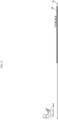
- FIG. 2 illustrates an example of a location of an image of a 3D augmented reality head-up display according to an example embodiment.
- the 3D augmented reality head-up display may represent a location of an imaginary image, that is, a virtual image 24 viewed with eyes of a user as a 3D perspective laid to correspond to a floor, that is, the ground 25, in front of a driver.
- An image through an optical system of a general vehicular head-up display is located at a fixed distance of 2 to 3 millimeter (m) in front of the driver and is generally perpendicular to the ground 25.
- the 3D augmented reality head-up display according to an example embodiment is to locate the virtual image 24 on a virtual plane corresponding to the ground 25 in front of the driver.
- the 3D augmented reality head-up display employs a scheme of creating the virtual image 24 visible with eyes by reflecting through an optical system of the head-up display, not a scheme of creating an actual image by directly projecting onto a screen, such as a general projector.
- Main information provided from a vehicular navigation corresponds to route information on a road being driven, lane information, and information on a distance from a vehicle in front.
- ADAS advanced driver-assistance system
- the information generally includes lane information, information on a distance from a vehicle in front/next, and unexpected information.
- a vehicle that is an entity to be driven may need to provide a passenger with information on a situation that may happen in the future, such as, for example, a turn or a lane change on a road during an autonomous driving.
- the route information may include turn-by-turn (TBT) information that guides straight forward and turn as information used to guide a route.
- TBT turn-by-turn
- the lane information 31 may refer to driving information or navigation information to be displayed on a lane as information on a driving lane.
- the 3D augmented reality head-up display may represent a virtual screen as a 3D perspective laid to correspond to the ground and thereby may implement information desired to transfer to the user as augmented reality on the road surface actually gazed by the user while driving without a need to shift the focus of eyes from a point of view of the user while driving to another location in various driving environments.
- a head-up display of an aftermarket product is generally implemented using a combiner (freeform mirror) scheme.
- a built-in product is generally implemented using a windshield reflection scheme of directly reflecting image light on a windshield of a vehicle without using an additional part (combiner).
- the 3D augmented reality head-up display includes a combination function of combining light from a light source and light from outside (foreground) and transferring the combined light to eyes of a driver and an optical function (3D function) of creating a 3D virtual reality image based on a point of view of the driver by matching a virtual image to the ground in front of the driver.
- the 3D augmented reality head-up display relates to using the windshield reflection scheme.
- the windshield functions as the combination function and may use the optical part that includes a freeform surface mirror (hereinafter, also referred to as a freeform mirror) for the 3D function.
- a freeform surface mirror hereinafter, also referred to as a freeform mirror
- a 3D augmented reality head-up display 400 relates to a configuration of creating a virtual 3D image through a reflection scheme that includes a windshield 40, and may include a display device 401 configured to function as a light source and a freeform mirror 402 configured to focus an imaginary image on the ground in front of a driver by reflecting light from the light source to the windshield 40.
- the windshield 40 may also function to simultaneously reflect the light from the light source reflected by the freeform mirror 402 toward an eye-box (a location of an eye of the driver) and to transmit light from outside (front).
- the 3D augmented reality head-up display 400 may locate the imaginary image on the ground in front of the driver by including a structure of projecting the light from the light source onto the ground through the freeform mirror 402 and the windshield 40.
- the 3D augmented reality head-up display 400 of the windshield reflection scheme may be implemented by deriving locations and angles of the display device 401 and the freeform mirror 402 relative to the ground into consideration of an angle of the windshield 40.
- FIG. 5 illustrates an example of an optical design configuration of a 3D augmented reality head-up display of a windshield reflection scheme according to an example embodiment.
- a 3D augmented reality head-up display 400 of a windshield reflection scheme may be in a structure in which light emitted from the display device 401 is located toward a far-field ray and transferred to the freeform mirror 402 in an optical path of an image transmitted from the display device 401, and may further include a fold mirror 403 configured to reduce an entire size of the optical path.
- the windshield 40 and the fold mirror 403 have no optical power.
- the far-field ray may refer to a ray that forms a virtual image at the farthest distance on the ground based on the driver among rays reflected by the display device 401 and extending to the ground to focus the virtual image on the ground.
- a ray that forms the virtual image at the nearest distance on the ground based on the driver among rays reflected by the display device 401 and extending to the ground to focus the virtual image on the ground may be referred to as a near-field ray.
- Reducing the entire size of the optical path represents reducing an entire size of an area occupied by the path through which the light is emitted from the display device 401 and finally reaches the windshield.
- the entire length of the optical path may be identical, but the entire size of the area occupied by the optical path may be reduced.
- the light reflected by the display device 401 may be directly transferred from the display device 401 to the freeform mirror 402 or may be reflected and transferred through the fold mirror 403.
- the light from the light source may be implemented in a structure to be transferred to the freeform mirror 402 at a location close to the far-field ray.
- FIG. 6 For clarity of description of a process of deriving a theoretical relational equation between the display device 401 and the freeform mirror 402 to focus the virtual image on the ground, as an equivalent structure in which an optical path changed by the fold mirror 403 and the windshield 40 is simplified as illustrated in FIG. 6 , illustration of the fold mirror 403 and the windshield 40 having no optical function aside from a function of changing the optical path may be omitted and a location of the display device 401 may be represented at a symmetrical location based on the fold mirror 403.
- a display plane 71 corresponding to the display device 401, a freeform mirror plane 72 corresponding to the freeform mirror 402, and a virtual image plane 73 corresponding to the ground may be added.
- the virtual image plane 73 may rotate to be parallel to the ground and may be expressed in a state of being inverted left and right based on an Y axis (a vertical axis in the figure).
- the 3D augmented reality head-up display 400 of the windshield reflection scheme may include a structure in which light emitted from the display device 401 is transferred to the freeform mirror 402 at an upper location than the freeform mirror 402, that is, a structure in which the display device 401 is located toward a far-field ray compared to a near-field ray close to a location of the driver among rays emitted toward the ground to focus the virtual image on the ground.
- FIG. 9 illustrate another example of an optical design configuration of a 3D augmented reality head-up display of a windshield reflection scheme according to an example embodiment
- FIG. 10 illustrates still another example of an optical design configuration of a 3D augmented reality head-up display of a windshield reflection scheme according to an example embodiment.
- the 3D augmented reality head-up display 400 of the windshield reflection scheme may be in a structure in which light emitted from the display device 401 is located toward a near-field ray and transferred to the freeform mirror 402 and may further include the fold mirror 403 configured to reduce the entire size of the optical path. Likewise, it is assumed that the windshield 40 and the fold mirror 403 have no optical power.
- the light emitted from the display device 401 may be directly transferred from the display device 401 to the freeform mirror 402 or may be reflected and transferred through the fold mirror 403.
- the light from the light source may be transferred from a location close to the near field ray to the freeform mirror 402.
- a light travel path may be implemented in order of the display device 401, the fold mirror 403, the freeform mirror 402, the windshield 40, and the driver. Also, as illustrated in FIG. 10 , the light may be transferred in order of the display device 401, the freeform mirror 402, the fold mirror 403, and the windshield 40.
- the display plane 71 corresponding to the display device 401, the freeform mirror plane 72 corresponding to the freeform mirror 402, and the virtual image plane 73 corresponding to the ground may be added.
- the virtual image plane 73 may rotate to be parallel to the ground and may be expressed in a state of being inverted left and right based on an Y axis (a vertical axis in the figure).
- the 3D augmented reality head-up display 400 of the windshield reflection scheme may include a structure in which light emitted from the display device 401 is transferred to the freeform mirror 402 at a lower location than the freeform mirror 402, that is, a structure in which the display device 401 is located toward a near-field ray relatively close to a location of the driver among rays emitted toward the ground to focus the virtual image on the ground.
- the display device 401 is located to be above the freeform mirror 402 and thereby located toward a far-field ray in front of the driver as illustrated in FIG. 14 .
- a display device capable of adjusting an angle of light emission that is, a display device that includes an additional optical element, such as a diffraction element, a micro-lens array, and a digital micromirror device, may be used, thereby ensuring the light efficiency.
- the display device 401 is located to be below the freeform mirror 402 and thereby located toward a near-field ray in front of the driver as illustrated in FIG. 16 .
- an actual path through which light travels starts from the display device 401 and is reflected by the freeform mirror 402 and the windshield 40 and, here, the reflected light reaches the eye of the driver and is focused on the retina by the lens.
- an image viewed by the user is the virtual image 24, not an actual image at a location of the display plane 71 at which the actual image is created.
- the virtual image 24 is located on the virtual image plane 73 that is a virtual plane corresponding to the ground. That is, the display plane 71 meets an imaging condition with the virtual image plane 73 through the freeform mirror 402.
- a theoretical relational equation between the display device 401 and the freeform mirror 402 to create the virtual image at a location corresponding to the ground may be derived based on an imaging condition between the display plane 71 corresponding to the display device 401 excluding the eye of the user, the freeform mirror plane 72 corresponding to the freeform mirror 402, and the virtual image plane 73 corresponding to the ground. Also, a focal length of the freeform mirror plane 72 may be a single variable of the imaging condition.
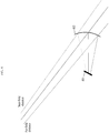
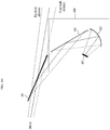
- FIG. 18 illustrates variables required to derive a relational equation between the display device 401 and the freeform mirror 402.
- an intersection (I) between the display plane 71 and the freeform mirror plane 72 may be present on the ground. That is, the display plane 71, the freeform mirror plane 72, and the virtual image plane 73 may simultaneously intersect at a predetermined location (I).
- An optical system may be set such that the display plane 71, the freeform mirror plane 72, and the virtual image plane 73 may meet the imaging condition under the above condition.
- DP represents the display plane 71 corresponding to the display device 401
- FMP represents the freeform mirror plane 72 corresponding to the freeform mirror 402
- IP represents the virtual image plane 73 that indicates a plane itself corresponding to the ground.
- C represents an optical center of the freeform mirror 402 relative to the display device 401.
- C may not necessarily to be located on the actual freeform mirror 402 and an offset may be applied at a location of the freeform mirror 402 based on a location of a user gaze.
- the offset may be set to a greater value.
- the offset may be set to a smaller value. Accordingly, as the user gaze is set at the higher location, the freeform mirror 402 may be installed to be high. As the user gaze is set at the lower location, the freeform mirror 402 may be installed to be low. Regardless of this change, a mathematical relational equation between the overall optical system and internal components may be maintained to be the same.
- I represents an intersection at which the DP 71, the FMP 72, and the IP 73 meet
- J represents a point at which a straight line that is parallel to the DP 71 and passes the center C intersects the IP 73
- K refers to an intersection with the normal of the freeform mirror 402 on the IP 73 and represents a point at which a straight line that is perpendicular to the FMP 72 and passes the center C intersects the IP 73.
- ⁇ ( ⁇ E , ⁇ S ) represents an angle of a location that meets the imaging condition on the DP 71 and the IP 73 based on a straight line that passes the center C and the intersection K.
- the imaging condition refers to a condition that light emitted from the light source in an omnidirectional solid angle reaches the same point of the virtual image (VI) by the freeform mirror.
- that the imaging condition is met represents that, as locations and angles of the display device 401, the freeform mirror, and of the IP 73 at which the virtual image (VI) is created, and a focal length (f) of the freeform mirror meet a lens formula, the light emitted from the display device 401 converges on the IP 73 through the freeform mirror and the virtual image (VI) is created on the IP 73.
- a focal length (f) of the freeform mirror meet a lens formula
- ⁇ represents an angle of the DP 71 based on the IP 73 or the ground
- ⁇ represents an angle of the FMP 72 based on the IP 73 or the ground
- ⁇ represents an angle between the DP 71 and the FMP 72.
- h represents a distance from the IP 73 or the ground to the center C
- h' represents a value acquired by adding an offset (positive number or negative number) toward an h direction to h (a height of the actual freeform mirror 402).
- h' corresponds to a case in which an offset according to the location of the user gaze is applied to the location of the freeform mirror 402.
- S represents a length between the intersection I and the intersection J, that is, a separation distance between the DP 71 and the FMP 72 at the height h in an axial direction parallel to the ground.
- S' (see FIG. 19 ) represents a separation distance between the DP 71 and the FMP 72 at the height h' (see FIG. 19 ) in the axial direction parallel to the ground.
- d S represents a distance from an orthogonal location C' between the center C of the freeform mirror 402 and the IP 73 or the ground to a location at which the virtual image (VI) starts, on the IP 73 or the plane corresponding to the ground.
- d E represents a distance from the orthogonal location C' between the center C of the freeform mirror 402 and the IP 73 or the ground to a location at which the virtual image (VI) ends on the IP 73 or the plane corresponding to the ground.
- d I represents a size of the virtual image (VI), and f represents the focal length of the freeform mirror 402.
- Equation 1 If an imaging condition between the DP 71 and the IP 73 is applied, the following Equation 1 is established.
- Equation 1 all of y, ⁇ , h, and f are assumed as positive numbers.
- Equation 1 h denotes a height from the ground to a location of the 3D augmented reality head-up display 400 on a dashboard in a general vehicle (accurately, a height to the optical center C of the freeform mirror 402). Also, f denotes a focal length of the freeform mirror 402 of the 3D augmented reality head-up display 400 having a general size and curvature.
- S may be derived using h, ⁇ , ⁇ , and ⁇ through Equation 2.
- S h sin ⁇ sin ⁇ sin ⁇
- d S , d E , and di may be derived through Equation 3.
- d S h tan ⁇ + ⁇ S
- d E h tan ⁇ + ⁇ E
- I h tan ⁇ + ⁇ E ⁇ tan ⁇ + ⁇ S
- ⁇ ( ⁇ E , ⁇ S ) denotes a positive number or a negative number based on a straight line that passes the center C and the intersection K.
- ds and d I may be calculated.
- an optical configuration may be optimized by adjusting at least one of ⁇ ( ⁇ E , ⁇ S ), ⁇ , and ⁇ .
- angles of the DP 71 and the FMP 72 relative to the ground and the location and the size of the virtual image (VI) may be derived.
- FIG. 19 illustrates an example of describing a location of the freeform mirror 402 that is determined based on an eye-box (a location of pupil) by the 3D augmented reality head-up display 400.
- a required height of an eye-box (a location of pupil) may be generally determined as a height at which an eye is located when a driver sits in the driver's seat.
- a distance between the eye-box and the freeform mirror 402 is determined as a distance from the eye to the freeform mirror 402 of the 3 augmented reality head-up display 400.
- the height h' of the location of the freeform mirror 402 is determined by including an offset based on a location of the eye-box and the location may not necessarily include the optical center C of the freeform mirror 402.
- the separation distance s' between the DP 71 and the FMP 72 may be determined based on h'.
- s' may be referred to as a distance between the display device 401 and the freeform mirror 402.
- an angle ⁇ ( ⁇ E , ⁇ S ) of a location that meets the imaging condition on the DP 71 and the IP 73 and an orientation angle of the DP 71 and an orientation angle of the IP 73 match as illustrated in FIG. 20 .
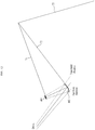
- FIG. 21 illustrate variables required to derive angles of the display device 401 and the freeform mirror 402 into consideration of the windshield 40 and the fold mirror 403.
- FIG. 21 illustrates an optical design configuration of a structure in which the display device 401 is located to be close to a near-field ray.
- ⁇ represents an angle of the display device 401 based on the ground
- ⁇ represents an angle of the freeform mirror 402 based on the ground
- o represents an angle of the fold mirror 403 based on the ground
- ⁇ represents an angle of the windshield 40 based on the ground.
- angles of the display device 401 and the freeform mirror 402 may be derived as follows based on the theoretical relational equation between the display device 401 and the freeform mirror 402 described above with reference to FIG. 18 .
- the angle of the display dvice 401 may be derived using the angle ( ⁇ ) of the DP 71 that meets the imaging condition and may be derived through, for example, Equation 4 or Equation 5.
- the angle of the freeform mirror 402 may be derived using the angle ( ⁇ ) of the FMP 72 that meets the imaging condition and may be derived through, for example, Equation 6.
- ⁇ ⁇ + 2 ⁇
- the 3D augmented reality head-up display 400 may implement a virtual image (VI) of a 3D perspective laid to correspond to the ground in front of the driver using the windshield reflection scheme through the display device 401 and the freeform mirror 402 based on the above relational equation.
- VI virtual image
- the 3D augmented reality head-up display 400 of the windshield reflection scheme of locating a virtual 3D image on the ground by deriving the angle of the display device 401 based on the ground using the angle ( ⁇ ) of the DP 71 and by deriving the angle of the freeform mirror 402 based on the ground using the angle ( ⁇ ) of the FMP 72 at a location at which the imaging condition between the DP 71 and the IP 73 is met may be implemented.
- a 3D augmented reality head-up display may create augmented reality of a 3D virtual image based on a point of view of a driver by matching a virtual image to the ground using a windshield reflection scheme.
- a structure capable of maximizing light efficiency of an optical system for creating a virtual 3D image matched to the ground in a structure that includes a windshield.
- the apparatuses described herein may be implemented using hardware components, software components, or a combination thereof.
- the apparatuses and the components described herein may be implemented using one or more general-purpose or special purpose computers, such as, for example, a processor, a controller, an arithmetic logic unit (ALU), a digital signal processor, a microcomputer, a field programmable gate array (FPGA), a programmable logic unit (PLU), a microprocessor, or any other device capable of responding to and executing instructions in a defined manner.
- the processing device may run an operating system (OS) and one or more software applications that run on the OS.
- the processing device also may access, store, manipulate, process, and create data in response to execution of the software.
- OS operating system
- the processing device also may access, store, manipulate, process, and create data in response to execution of the software.
- a processing device may include multiple processing elements and/or multiple types of processing elements.
- a processing device may include multiple processors or a processor and a controller.
- different processing configurations are possible, such as parallel processors.
- the software may include a computer program, a piece of code, an instruction, or some combination thereof, for independently or collectively instructing or configuring the processing device to operate as desired.
- Software and/or data may be embodied in any type of machine, component, physical equipment, virtual equipment, computer storage medium or device, to be interpreted by the processing device or to provide an instruction or data to the processing device.
- the software also may be distributed over network coupled computer systems so that the software is stored and executed in a distributed fashion.
- the software and data may be stored by one or more computer readable storage media.
- the methods according to the above-described example embodiments may be configured in a form of program instructions performed through various computer devices and recorded in non-transitory computer-readable media.
- the media may continuously store computer-executable programs or may transitorily store the same for execution or download.
- the media may be various types of recording devices or storage devices in a form in which one or a plurality of hardware components are combined. Without being limited to media directly connected to a computer system, the media may be distributed over the network.
- Examples of the media include magnetic media such as hard disks, floppy disks, and magnetic tapes; optical media such as CD-ROM and DVDs; magneto-optical media such as floptical disks; and hardware devices that are specially configured to store program instructions, such as read-only memory (ROM), random access memory (RAM), flash memory, and the like.
- Examples of other media may include record media and storage media managed by an app store that distributes applications or a site that supplies and distributes other various types of software, a server, and the like.
Landscapes
- Engineering & Computer Science (AREA)
- Chemical & Material Sciences (AREA)
- Combustion & Propulsion (AREA)
- Transportation (AREA)
- Mechanical Engineering (AREA)
- Physics & Mathematics (AREA)
- General Physics & Mathematics (AREA)
- Optics & Photonics (AREA)
- Instrument Panels (AREA)
- Controls And Circuits For Display Device (AREA)
- Lenses (AREA)
Abstract
Description
- One or more example embodiments of the following description relate to a three-dimensional (3D) head-up display.
-
FIG. 1 illustrates a view for describing a focus adjustment to verify information of a general head-up display device. - Referring to
FIG. 1 , the general vehicular head-up display (HUD) device refers to a vehicular display device that minimizes an unnecessary distraction of a driver by transmitting an image, such as, for example, a current speed, a fuel level, and navigation route guide information, from adisplay 10 and by projecting the image as a graphic image on awindshield 13 in front of the driver throughoptical systems optical systems display 10. The above vehicular head-up display device may induce an immediate response from the driver and may provide convenience at the same time. - In the general vehicular head-up display (HUD) device, an image is fixably present at about 2 to 3 millimeter (m) in front of a user. In contrast, when driving, a gaze distance of a driver is a close distance to about 300 m. Therefore, the driver drives the vehicle while gazing at a far distance and, to verify information of the head-up display (HUD) device, there is an inconvenience to largely adjust the focus of eyes. That is, the focus of the driver may be repeatedly adjusted between a far distance at which the main field of view (FOV) is present and ~3 m in which the image is formed.
- Accordingly, there is a need for development of a three-dimensional (3D) head-up display device that may implement augmented reality in a driving environment and may be free from restrictions on an image expression distance such that the driver may acquire desired information without changing the focus of eyes at a point of view, that is, a perspective at which the driver is gazing while driving.
- For example, Korean Patent Registration No.
10-1409846 - One or more example embodiments provide a three-dimensional (3D) augmented reality head-up display that may create augmented reality of a 3D virtual image based on a point of view of a driver by matching a virtual image to the ground using a windshield reflection scheme.
- One or more example embodiments provide a structure capable of maximizing light efficiency of an optical system for creating a virtual 3D image matched to the ground in a structure that includes a windshield.
- According to an aspect of at least one example embodiment, there is provided a three-dimensional (3D) augmented reality head-up display including a display device configured to function as a light source; and a freeform surface mirror configured to reflect light from the light source toward a windshield of a vehicle, and including a structure in which an image created by the light from the light source is focused on the ground in front of the vehicle as a virtual image of a 3D perspective through a reflection scheme of reflecting the light from the light source on the windshield by the freeform surface mirror.
- According to an aspect, the windshield may include a function of simultaneously reflecting the light from the light source reflected by the freeform surface mirror toward an eye-box and transmitting light from outside.
- According to another aspect, the 3D augmented reality head-up display may include a structure in which the light from the light source is transferred to the freeform surface mirror at a lower location than the freeform surface mirror, as a structure in which the display device is located toward a near-field ray among rays that extend to the ground to focus the virtual image on the ground.
- According to another aspect, the 3D augmented reality head-up display may further include a fold mirror configured to reduce an entire size of a light path, and a structure in which the light from the light source is transferred in order of the display device, the fold mirror, the freeform surface mirror, and the windshield, or in order of the display device, the freeform surface mirror, the fold mirror, and the windshield.
- According to still another aspect, a display plane corresponding to the display device may meet an imaging condition with a virtual image plane corresponding to the ground through the freeform surface mirror.
- According to still another aspect, the virtual image may be created based on an imaging condition between a display plane corresponding to the display device and a mirror plane corresponding to the freeform surface mirror and a virtual image plane corresponding to the ground.
- According to still another aspect, an angle of the display device may be determined based on an angle of the display plane that meets the imaging condition.
- According to still another aspect, an angle of the display device may be determined based on an angle of the display plane, an angle of the windshield, and an angle of a fold mirror that meet the imaging condition.
- According to still another aspect, an angle of the freeform surface mirror may be determined based on an angle of the mirror plane and an angle of the windshield that meet the imaging condition.
- According to still another aspect, a start location and a size of the virtual image may be determined using an angle that meets the imaging condition on the display plane and the virtual image plane based on a straight line that passes a point at which the normal of the freeform surface mirror and the virtual image plane intersect and an optical center of the freeform surface mirror.
- According to still another aspect, a start location and a size of the virtual image may be adjusted based on at least one of the angle, an angle of the display plane based on the virtual image plane, an angle between the display plane and the mirror plane, and a height from the virtual image plane to an optical center of the freeform surface mirror.
- According to still another aspect, a separation distance between the display device and the freeform surface mirror at a height from the virtual image plane to the freeform surface mirror may be derived based on a height value acquired by adding an offset toward a corresponding height direction to a height from the virtual image plane to an optical center of the freeform surface mirror, an angle of the display plane based on the virtual image plane, an angle of the mirror plane based on the virtual image plane, and an angle between the display plane and the mirror plane.
- According to still another aspect, a location of the freeform surface mirror may be determined using a height that includes an offset according to a required location of an eye-box.
- According to some example embodiments, it is possible to provide a three-dimensional (3D) augmented reality head-up display that may create augmented reality of a 3D virtual image based on a point of view of a driver by matching a virtual image to the ground using a windshield reflection scheme.
- According to some example embodiments, it is possible to provide a structure capable of maximizing light efficiency of an optical system for creating a virtual 3D image matched to the ground in a structure that includes a windshield.
-
-
FIG. 1 illustrates a view for describing a focus adjustment to verify information of a general head-up display device. -
FIG. 2 illustrates an example of a location of an image of a three-dimensional (3D) augmented reality head-up display according to an example embodiment. -
FIG. 3 illustrates examples of providing an image on a virtual plane corresponding to the ground, such as a road surface, according to an example embodiment. -
FIG. 4 illustrates an example of a 3D augmented reality head-up display of a windshield reflection scheme according to an example embodiment. -
FIG. 5 illustrates an example of an optical design configuration of a 3D augmented reality head-up display of a windshield reflection scheme according to an example embodiment. -
FIGS. 6 to 8 illustrate examples of equivalent expression for deriving a theoretical relational equation of the optical design configuration ofFIG. 5 according to an example embodiment. -
FIG. 9 illustrate another example of an optical design configuration of a 3D augmented reality head-up display of a windshield reflection scheme according to an example embodiment. -
FIG. 10 illustrates still another example of an optical design configuration of a 3D augmented reality head-up display of a windshield reflection scheme according to an example embodiment. -
FIGS. 11 to 13 illustrate examples of equivalent expression for deriving a theoretical relational equation of the optical design configuration ofFIG. 9 according to an example embodiment. -
FIGS. 14 to 17 illustrate example of describing light efficiency according to an optical design configuration of a 3D augmented reality head-up display according to an example embodiment. -
FIG. 18 illustrates variables required to derive a relational equation between a display device and a freeform mirror of a 3D augmented reality head-up display according to an example embodiment. -
FIG. 19 illustrates an example of describing a location of a freeform mirror determined based on an eye-box (a location of pupil) according to an example embodiment. -
FIG. 20 illustrates an example of an imaging condition between a display plane and a freeform mirror plane and a virtual image plane according to an example embodiment. -
FIG. 21 illustrates variables required to derive angles of a display device and a freeform mirror of a 3D augmented reality head-up display of a windshield reflection scheme according to an example embodiment. - Hereinafter, example embodiments will be described with reference to the accompanying drawings.
- The following example embodiments may be modified in various forms and the scope of the disclosure is not limited to the following example embodiments. Also, the various example embodiments are provided to further fully explain the disclosure to those skilled in the art. Shapes and sizes of elements illustrated in the figures may be simplified or may be reduced or exaggerated for simplicity of description.
- In addition to the existing head-up display described with
FIG. 1 , many displays, such as a television (TV), a monitor, a projector screen, and a virtual reality (VR) / augmented reality (AR) glass, are provided in a direction perpendicular to a gaze of a user. - The example embodiments provide a three-dimensional (3D) augmented reality head-up display having a 3D implementation scheme in a form of locating an image to correspond to the ground. In particular, the example embodiments may provide a 3D augmented reality head-up display optimized for a point of view of a driver in a driving environment by representing a virtual screen as a 3D perspective laid to correspond to the ground.
-
FIG. 2 illustrates an example of a location of an image of a 3D augmented reality head-up display according to an example embodiment. - Referring to
FIG. 2 , the 3D augmented reality head-up display according to an example embodiment may represent a location of an imaginary image, that is, avirtual image 24 viewed with eyes of a user as a 3D perspective laid to correspond to a floor, that is, theground 25, in front of a driver. - An image through an optical system of a general vehicular head-up display is located at a fixed distance of 2 to 3 millimeter (m) in front of the driver and is generally perpendicular to the
ground 25. Dissimilarly, the 3D augmented reality head-up display according to an example embodiment is to locate thevirtual image 24 on a virtual plane corresponding to theground 25 in front of the driver. - The 3D augmented reality head-up display according to an example embodiment employs a scheme of creating the
virtual image 24 visible with eyes by reflecting through an optical system of the head-up display, not a scheme of creating an actual image by directly projecting onto a screen, such as a general projector. - Main information provided from a vehicular navigation corresponds to route information on a road being driven, lane information, and information on a distance from a vehicle in front. Also, an advanced driver-assistance system (ADAS) provides safety related information to the driver. Here, the information generally includes lane information, information on a distance from a vehicle in front/next, and unexpected information. Likewise, a vehicle that is an entity to be driven may need to provide a passenger with information on a situation that may happen in the future, such as, for example, a turn or a lane change on a road during an autonomous driving. The route information may include turn-by-turn (TBT) information that guides straight forward and turn as information used to guide a route.
- Referring to
FIG. 3 , it is very important and effective to display the aforementioned information, for example,lane information 31 andinformation 32 on a distance from a vehicle in front, as a virtual image on an actual road surface at a point of view of the driver. Thelane information 31 may refer to driving information or navigation information to be displayed on a lane as information on a driving lane. - The 3D augmented reality head-up display according to an example embodiment may represent a virtual screen as a 3D perspective laid to correspond to the ground and thereby may implement information desired to transfer to the user as augmented reality on the road surface actually gazed by the user while driving without a need to shift the focus of eyes from a point of view of the user while driving to another location in various driving environments.
- A head-up display of an aftermarket product is generally implemented using a combiner (freeform mirror) scheme. A built-in product is generally implemented using a windshield reflection scheme of directly reflecting image light on a windshield of a vehicle without using an additional part (combiner).
- The 3D augmented reality head-up display according to an example embodiment includes a combination function of combining light from a light source and light from outside (foreground) and transferring the combined light to eyes of a driver and an optical function (3D function) of creating a 3D virtual reality image based on a point of view of the driver by matching a virtual image to the ground in front of the driver.
- The 3D augmented reality head-up display according to an example embodiment relates to using the windshield reflection scheme. Here, the windshield functions as the combination function and may use the optical part that includes a freeform surface mirror (hereinafter, also referred to as a freeform mirror) for the 3D function.
- Referring to
FIG. 4 , a 3D augmented reality head-updisplay 400 according to an example embodiment relates to a configuration of creating a virtual 3D image through a reflection scheme that includes awindshield 40, and may include adisplay device 401 configured to function as a light source and afreeform mirror 402 configured to focus an imaginary image on the ground in front of a driver by reflecting light from the light source to thewindshield 40. Thewindshield 40 may also function to simultaneously reflect the light from the light source reflected by thefreeform mirror 402 toward an eye-box (a location of an eye of the driver) and to transmit light from outside (front). - That is, the 3D augmented reality head-up
display 400 may locate the imaginary image on the ground in front of the driver by including a structure of projecting the light from the light source onto the ground through thefreeform mirror 402 and thewindshield 40. - The 3D augmented reality head-up
display 400 of the windshield reflection scheme may be implemented by deriving locations and angles of thedisplay device 401 and thefreeform mirror 402 relative to the ground into consideration of an angle of thewindshield 40. -
FIG. 5 illustrates an example of an optical design configuration of a 3D augmented reality head-up display of a windshield reflection scheme according to an example embodiment. - Referring to
FIG. 5 , a 3D augmented reality head-updisplay 400 of a windshield reflection scheme according to an example embodiment may be in a structure in which light emitted from thedisplay device 401 is located toward a far-field ray and transferred to thefreeform mirror 402 in an optical path of an image transmitted from thedisplay device 401, and may further include afold mirror 403 configured to reduce an entire size of the optical path. Here, it is assumed that thewindshield 40 and thefold mirror 403 have no optical power. - The far-field ray may refer to a ray that forms a virtual image at the farthest distance on the ground based on the driver among rays reflected by the
display device 401 and extending to the ground to focus the virtual image on the ground. Conversely, a ray that forms the virtual image at the nearest distance on the ground based on the driver among rays reflected by thedisplay device 401 and extending to the ground to focus the virtual image on the ground may be referred to as a near-field ray. - Reducing the entire size of the optical path represents reducing an entire size of an area occupied by the path through which the light is emitted from the
display device 401 and finally reaches the windshield. In the case of using thefold mirror 403, the entire length of the optical path may be identical, but the entire size of the area occupied by the optical path may be reduced. - The light reflected by the
display device 401 may be directly transferred from thedisplay device 401 to thefreeform mirror 402 or may be reflected and transferred through thefold mirror 403. Here, the light from the light source may be implemented in a structure to be transferred to thefreeform mirror 402 at a location close to the far-field ray. - For clarity of description of a process of deriving a theoretical relational equation between the
display device 401 and thefreeform mirror 402 to focus the virtual image on the ground, as an equivalent structure in which an optical path changed by thefold mirror 403 and thewindshield 40 is simplified as illustrated inFIG. 6 , illustration of thefold mirror 403 and thewindshield 40 having no optical function aside from a function of changing the optical path may be omitted and a location of thedisplay device 401 may be represented at a symmetrical location based on thefold mirror 403. Next, as illustrated inFIG. 7 , adisplay plane 71 corresponding to thedisplay device 401, afreeform mirror plane 72 corresponding to thefreeform mirror 402, and avirtual image plane 73 corresponding to the ground may be added. As illustrated inFIG. 8 , thevirtual image plane 73 may rotate to be parallel to the ground and may be expressed in a state of being inverted left and right based on an Y axis (a vertical axis in the figure). - Referring to
FIG. 8 , the 3D augmented reality head-updisplay 400 of the windshield reflection scheme may include a structure in which light emitted from thedisplay device 401 is transferred to thefreeform mirror 402 at an upper location than thefreeform mirror 402, that is, a structure in which thedisplay device 401 is located toward a far-field ray compared to a near-field ray close to a location of the driver among rays emitted toward the ground to focus the virtual image on the ground. -
FIG. 9 illustrate another example of an optical design configuration of a 3D augmented reality head-up display of a windshield reflection scheme according to an example embodiment, andFIG. 10 illustrates still another example of an optical design configuration of a 3D augmented reality head-up display of a windshield reflection scheme according to an example embodiment. - Referring to
FIGS. 9 and10 , the 3D augmented reality head-updisplay 400 of the windshield reflection scheme according to an example embodiment may be in a structure in which light emitted from thedisplay device 401 is located toward a near-field ray and transferred to thefreeform mirror 402 and may further include thefold mirror 403 configured to reduce the entire size of the optical path. Likewise, it is assumed that thewindshield 40 and thefold mirror 403 have no optical power. - The light emitted from the
display device 401 may be directly transferred from thedisplay device 401 to thefreeform mirror 402 or may be reflected and transferred through thefold mirror 403. Here, the light from the light source may be transferred from a location close to the near field ray to thefreeform mirror 402. - As illustrated in
FIG. 9 , a light travel path may be implemented in order of thedisplay device 401, thefold mirror 403, thefreeform mirror 402, thewindshield 40, and the driver. Also, as illustrated inFIG. 10 , the light may be transferred in order of thedisplay device 401, thefreeform mirror 402, thefold mirror 403, and thewindshield 40. - For clarity of description of a process of deriving a theoretical relational equation between the
display device 401 and thefreeform mirror 402 to focus the virtual image on the ground with respect to the optical design configuration ofFIG. 9 , as an equivalent structure in which an optical path changed by thefold mirror 403 and thewindshield 40 is simplified as illustrated inFIG. 11 , illustration of thefold mirror 403 and thewindshield 40 having no optical function aside from a function of chanting the optical path may be omitted and a location of thedisplay device 401 may be represented at a symmetrical location based on thefold mirror 403. Next, as illustrated inFIG. 12 , thedisplay plane 71 corresponding to thedisplay device 401, thefreeform mirror plane 72 corresponding to thefreeform mirror 402, and thevirtual image plane 73 corresponding to the ground may be added. As illustrated inFIG. 13 , thevirtual image plane 73 may rotate to be parallel to the ground and may be expressed in a state of being inverted left and right based on an Y axis (a vertical axis in the figure). - Referring to
FIG. 13 , the 3D augmented reality head-updisplay 400 of the windshield reflection scheme may include a structure in which light emitted from thedisplay device 401 is transferred to thefreeform mirror 402 at a lower location than thefreeform mirror 402, that is, a structure in which thedisplay device 401 is located toward a near-field ray relatively close to a location of the driver among rays emitted toward the ground to focus the virtual image on the ground. - When comparing output of each angle of light emitted from the
display device 401, output of a vertical component is highest and the further away from the vertical, the lower the output. Therefore, to use light of a vertical angle or a near-vertical angle due to low output may be advantageous in terms of light efficiency. - According to the equivalent structure of
FIG. 8 that represents the optical design configuration ofFIG. 5 , thedisplay device 401 is located to be above thefreeform mirror 402 and thereby located toward a far-field ray in front of the driver as illustrated inFIG. 14 . - If rotating the equivalent structure of
FIG. 8 that represents the optical design configuration ofFIG. 5 such that thefreeform mirror plane 72 may be vertical as illustrated inFIG. 15 , most of the light of a vertical component with strong output in the light emitted from thedisplay device 401 may be discarded and light with a relatively low output component may be mainly used. Therefore, there is a probability that light efficiency may decrease. - To apply an optical design configuration in which the
display device 401 is located above thefreeform mirror 402 to the 3D augmented reality head-updisplay 400 of the windshield reflection scheme, a display device capable of adjusting an angle of light emission, that is, a display device that includes an additional optical element, such as a diffraction element, a micro-lens array, and a digital micromirror device, may be used, thereby ensuring the light efficiency. - Meanwhile, according to the equivalent structure of
FIG. 13 that represents the optical design configuration ofFIG. 9 , thedisplay device 401 is located to be below thefreeform mirror 402 and thereby located toward a near-field ray in front of the driver as illustrated inFIG. 16 . - If rotating the equivalent structure of
FIG. 13 that represents the optical design configuration ofFIG. 9 such that thefreeform mirror plane 72 may be vertical as illustrated inFIG. 17 , most of the light of a vertical component with strong output in the light emitted from thedisplay device 401 may be used. Therefore, it can be said that the light efficiency is high. - An actual path through which light travels starts from the
display device 401 and is reflected by thefreeform mirror 402 and thewindshield 40 and, here, the reflected light reaches the eye of the driver and is focused on the retina by the lens. However, an image viewed by the user is thevirtual image 24, not an actual image at a location of thedisplay plane 71 at which the actual image is created. Here, thevirtual image 24 is located on thevirtual image plane 73 that is a virtual plane corresponding to the ground. That is, thedisplay plane 71 meets an imaging condition with thevirtual image plane 73 through thefreeform mirror 402. - A theoretical relational equation between the
display device 401 and thefreeform mirror 402 to create the virtual image at a location corresponding to the ground may be derived based on an imaging condition between thedisplay plane 71 corresponding to thedisplay device 401 excluding the eye of the user, thefreeform mirror plane 72 corresponding to thefreeform mirror 402, and thevirtual image plane 73 corresponding to the ground. Also, a focal length of thefreeform mirror plane 72 may be a single variable of the imaging condition. -
FIG. 18 illustrates variables required to derive a relational equation between thedisplay device 401 and thefreeform mirror 402. - Referring to
FIG. 18 , an intersection (I) between thedisplay plane 71 and thefreeform mirror plane 72 may be present on the ground. That is, thedisplay plane 71, thefreeform mirror plane 72, and thevirtual image plane 73 may simultaneously intersect at a predetermined location (I). An optical system may be set such that thedisplay plane 71, thefreeform mirror plane 72, and thevirtual image plane 73 may meet the imaging condition under the above condition. - DP represents the
display plane 71 corresponding to thedisplay device 401, FMP represents thefreeform mirror plane 72 corresponding to thefreeform mirror 402, and IP represents thevirtual image plane 73 that indicates a plane itself corresponding to the ground. - C represents an optical center of the
freeform mirror 402 relative to thedisplay device 401. Here, C may not necessarily to be located on the actualfreeform mirror 402 and an offset may be applied at a location of thefreeform mirror 402 based on a location of a user gaze. As the user gaze is set at a higher location, the offset may be set to a greater value. As the user gaze is set at a lower location, the offset may be set to a smaller value. Accordingly, as the user gaze is set at the higher location, thefreeform mirror 402 may be installed to be high. As the user gaze is set at the lower location, thefreeform mirror 402 may be installed to be low. Regardless of this change, a mathematical relational equation between the overall optical system and internal components may be maintained to be the same. - Hereinafter, the relational equation is induced with the assumption that C is located on the
freeform mirror 402. - I represents an intersection at which the
DP 71, theFMP 72, and theIP 73 meet, J represents a point at which a straight line that is parallel to theDP 71 and passes the center C intersects theIP 73, and K refers to an intersection with the normal of thefreeform mirror 402 on theIP 73 and represents a point at which a straight line that is perpendicular to theFMP 72 and passes the center C intersects theIP 73. - α (αE, αS) represents an angle of a location that meets the imaging condition on the
DP 71 and theIP 73 based on a straight line that passes the center C and the intersection K. Here, since the corresponding location meets the imaging condition, an orientation angle of theDP 71 and an orientation angle of theIP 73 match at all times. Here, the imaging condition refers to a condition that light emitted from the light source in an omnidirectional solid angle reaches the same point of the virtual image (VI) by the freeform mirror. InFIG. 18 , that the imaging condition is met represents that, as locations and angles of thedisplay device 401, the freeform mirror, and of theIP 73 at which the virtual image (VI) is created, and a focal length (f) of the freeform mirror meet a lens formula, the light emitted from thedisplay device 401 converges on theIP 73 through the freeform mirror and the virtual image (VI) is created on theIP 73. Here, although example embodiments describe an example in which not a real image but the virtual image (VI) is created, it will be understood by those skilled in the art that the light does not actually reach theIP 73 and an extending line of the emitted ray converges on theIP 73 to thereby form the virtual image (VI). - β represents an angle of the
DP 71 based on theIP 73 or the ground, γ represents an angle of theFMP 72 based on theIP 73 or the ground, and θ represents an angle between theDP 71 and theFMP 72. - h represents a distance from the
IP 73 or the ground to the center C, and h' (seeFIG. 19 ) represents a value acquired by adding an offset (positive number or negative number) toward an h direction to h (a height of the actual freeform mirror 402). Here, h' corresponds to a case in which an offset according to the location of the user gaze is applied to the location of thefreeform mirror 402. - S represents a length between the intersection I and the intersection J, that is, a separation distance between the
DP 71 and theFMP 72 at the height h in an axial direction parallel to the ground. - S' (see
FIG. 19 ) represents a separation distance between theDP 71 and theFMP 72 at the height h' (seeFIG. 19 ) in the axial direction parallel to the ground. - dS represents a distance from an orthogonal location C' between the center C of the
freeform mirror 402 and theIP 73 or the ground to a location at which the virtual image (VI) starts, on theIP 73 or the plane corresponding to the ground. - dE represents a distance from the orthogonal location C' between the center C of the
freeform mirror 402 and theIP 73 or the ground to a location at which the virtual image (VI) ends on theIP 73 or the plane corresponding to the ground. - dI represents a size of the virtual image (VI), and f represents the focal length of the
freeform mirror 402. - Initially, a relational equation among β, γ, and θ is expressed as follows.
- If an imaging condition between the
DP 71 and theIP 73 is applied, the following Equation 1 is established.
- In Equation 1, h denotes a height from the ground to a location of the 3D augmented reality head-up
display 400 on a dashboard in a general vehicle (accurately, a height to the optical center C of the freeform mirror 402). Also, f denotes a focal length of thefreeform mirror 402 of the 3D augmented reality head-updisplay 400 having a general size and curvature. - If Equation 1 is substituted with values of h and f, a numerical relation between θ and γmay be derived. Based on this, β may be derived through a relational expression β = γ + θ.
- Next, S may be derived using h, β, γ, and θ through Equation 2.

- Also, dS, dE, and di may be derived through
Equation 3.
- Here, α (αE, αS) denotes a positive number or a negative number based on a straight line that passes the center C and the intersection K.
- Using
Equation 3, ds and dI may be calculated. Here, if ds representing a start location of the virtual image (VI) and dI representing a size of the virtual image (VI) need to be adjusted, an optical configuration may be optimized by adjusting at least one of α (αE, αS), β, and θ. - Through the above relational equation, the angles of the
DP 71 and theFMP 72 relative to the ground and the location and the size of the virtual image (VI) may be derived. -
FIG. 19 illustrates an example of describing a location of thefreeform mirror 402 that is determined based on an eye-box (a location of pupil) by the 3D augmented reality head-updisplay 400. - Referring to
FIG. 19 , a required height of an eye-box (a location of pupil) may be generally determined as a height at which an eye is located when a driver sits in the driver's seat. A distance between the eye-box and thefreeform mirror 402 is determined as a distance from the eye to thefreeform mirror 402 of the 3 augmented reality head-updisplay 400. - The height h' of the location of the
freeform mirror 402 is determined by including an offset based on a location of the eye-box and the location may not necessarily include the optical center C of thefreeform mirror 402. The separation distance s' between theDP 71 and theFMP 72 may be determined based on h'. Here, s' may be referred to as a distance between thedisplay device 401 and thefreeform mirror 402. - If rotating the equivalent structure of
FIG. 13 that represents the optical design configuration ofFIG. 9 such that thefreeform mirror plane 72 may be vertical, an angle α (αE, αS) of a location that meets the imaging condition on theDP 71 and theIP 73 and an orientation angle of theDP 71 and an orientation angle of theIP 73 match as illustrated inFIG. 20 . - Likewise, in a structure in which the
display device 401 is located to be close to a far-field ray as well as in a structure in which thedisplay device 401 is located to be close to a near-field ray, positional angles aE and aS of the light source and the virtual image are unified at all times. -
FIG. 21 illustrate variables required to derive angles of thedisplay device 401 and thefreeform mirror 402 into consideration of thewindshield 40 and thefold mirror 403.FIG. 21 illustrates an optical design configuration of a structure in which thedisplay device 401 is located to be close to a near-field ray. - Referring to
FIG. 21 , δ represents an angle of thedisplay device 401 based on the ground, ε represents an angle of thefreeform mirror 402 based on the ground, o represents an angle of thefold mirror 403 based on the ground, and τ represents an angle of thewindshield 40 based on the ground. - The angles of the
display device 401 and thefreeform mirror 402 may be derived as follows based on the theoretical relational equation between thedisplay device 401 and thefreeform mirror 402 described above with reference toFIG. 18 . - The angle of the
display dvice 401 may be derived using the angle (β) of theDP 71 that meets the imaging condition and may be derived through, for example, Equation 4 or Equation 5.

- The angle of the
freeform mirror 402 may be derived using the angle (γ) of theFMP 72 that meets the imaging condition and may be derived through, for example, Equation 6.
- Therefore, the 3D augmented reality head-up
display 400 according to an example embodiment may implement a virtual image (VI) of a 3D perspective laid to correspond to the ground in front of the driver using the windshield reflection scheme through thedisplay device 401 and thefreeform mirror 402 based on the above relational equation. - The 3D augmented reality head-up
display 400 of the windshield reflection scheme of locating a virtual 3D image on the ground by deriving the angle of thedisplay device 401 based on the ground using the angle (β) of theDP 71 and by deriving the angle of thefreeform mirror 402 based on the ground using the angle (γ) of theFMP 72 at a location at which the imaging condition between theDP 71 and theIP 73 is met may be implemented. - According to some example embodiments, it is possible to provide a 3D augmented reality head-up display that may create augmented reality of a 3D virtual image based on a point of view of a driver by matching a virtual image to the ground using a windshield reflection scheme. In particular, it is possible to provide a structure capable of maximizing light efficiency of an optical system for creating a virtual 3D image matched to the ground in a structure that includes a windshield.
- The apparatuses described herein may be implemented using hardware components, software components, or a combination thereof. For example, the apparatuses and the components described herein may be implemented using one or more general-purpose or special purpose computers, such as, for example, a processor, a controller, an arithmetic logic unit (ALU), a digital signal processor, a microcomputer, a field programmable gate array (FPGA), a programmable logic unit (PLU), a microprocessor, or any other device capable of responding to and executing instructions in a defined manner. The processing device may run an operating system (OS) and one or more software applications that run on the OS. The processing device also may access, store, manipulate, process, and create data in response to execution of the software. For purpose of simplicity, the description of a processing device is used as singular; however, one skilled in the art will be appreciated that a processing device may include multiple processing elements and/or multiple types of processing elements. For example, a processing device may include multiple processors or a processor and a controller. In addition, different processing configurations are possible, such as parallel processors.
- The software may include a computer program, a piece of code, an instruction, or some combination thereof, for independently or collectively instructing or configuring the processing device to operate as desired. Software and/or data may be embodied in any type of machine, component, physical equipment, virtual equipment, computer storage medium or device, to be interpreted by the processing device or to provide an instruction or data to the processing device. The software also may be distributed over network coupled computer systems so that the software is stored and executed in a distributed fashion. The software and data may be stored by one or more computer readable storage media.
- The methods according to the above-described example embodiments may be configured in a form of program instructions performed through various computer devices and recorded in non-transitory computer-readable media. Here, the media may continuously store computer-executable programs or may transitorily store the same for execution or download. Also, the media may be various types of recording devices or storage devices in a form in which one or a plurality of hardware components are combined. Without being limited to media directly connected to a computer system, the media may be distributed over the network. Examples of the media include magnetic media such as hard disks, floppy disks, and magnetic tapes; optical media such as CD-ROM and DVDs; magneto-optical media such as floptical disks; and hardware devices that are specially configured to store program instructions, such as read-only memory (ROM), random access memory (RAM), flash memory, and the like. Examples of other media may include record media and storage media managed by an app store that distributes applications or a site that supplies and distributes other various types of software, a server, and the like.
- Although the example embodiments are described with reference to some specific example embodiments and accompanying drawings, it will be apparent to one of ordinary skill in the art that various alterations and modifications in form and details may be made in these example embodiments without departing from the spirit and scope of the claims and their equivalents. For example, suitable results may be achieved if the described techniques are performed in different order, and/or if components in a described system, architecture, device, or circuit are combined in a different manner, and/or replaced or supplemented by other components or their equivalents.
- Therefore, other implementations, other example embodiments, and equivalents of the claims are to be construed as being included in the claims.
Claims (13)
- A three-dimensional (3D) augmented reality head-up display comprising:a display device configured to function as a light source; anda freeform surface mirror configured to reflect light from the light source toward a windshield of a vehicle, andcomprising a structure in which an image created by the light from the light source is focused on the ground in front of the vehicle as a virtual image of a 3D perspective through a reflection scheme of reflecting the light from the light source on the windshield by the freeform surface mirror.
- The 3D augmented reality head-up display of claim 1, wherein the windshield comprises a function of simultaneously reflecting the light from the light source reflected by the freeform surface mirror toward an eye-box and transmitting light from outside.
- The 3D augmented reality head-up display of claim 1, comprising a structure in which the light from the light source is transferred to the freeform surface mirror at a lower location than the freeform surface mirror, as a structure in which the display device is located toward a near-field ray among rays that extend to the ground to focus the virtual image on the ground.
- The 3D augmented reality head-up display of claim 1, further com prising:a fold mirror configured to reduce an entire size of a light path, anda structure in which the light from the light source is transferred in order of the display device, the fold mirror, the freeform surface mirror, and the windshield, or in order of the display device, the freeform surface mirror, the fold mirror, and the windshield.
- The 3D augmented reality head-up display of claim 1, wherein a display plane corresponding to the display device meets an imaging condition with a virtual image plane corresponding to the ground through the freeform surface mirror.
- The 3D augmented reality head-up display of claim 1, wherein the virtual image is created based on an imaging condition between a display plane corresponding to the display device and a mirror plane corresponding to the freeform surface mirror and a virtual image plane corresponding to the ground.
- The 3D augmented reality head-up display of claim 6, wherein an angle of the display device is determined based on an angle of the display plane that meets the imaging condition.
- The 3D augmented reality head-up display of claim 6, wherein an angle of the display device is determined based on an angle of the display plane, an angle of the windshield, and an angle of a fold mirror that meet the imaging condition.
- The 3D augmented reality head-up display of claim 6, wherein an angle of the freeform surface mirror is determined based on an angle of the mirror plane and an angle of the windshield that meet the imaging condition.
- The 3D augmented reality head-up display of claim 6, wherein a start location and a size of the virtual image are determined using an angle that meets the imaging condition on the display plane and the virtual image plane based on a straight line that passes a point at which the normal of the freeform surface mirror and the virtual image plane intersect and an optical center of the freeform surface mirror.
- The 3D augmented reality head-up display of claim 9, wherein a start location and a size of the virtual image are adjusted based on at least one of the angle, an angle of the display plane based on the virtual image plane, an angle between the display plane and the mirror plane, and a height from the virtual image plane to an optical center of the freeform surface mirror.
- The 3D augmented reality head-up display of claim 6, wherein a separation distance between the display device and the freeform surface mirror at a height from the virtual image plane to the freeform surface mirror is derived based on a height value acquired by adding an offset toward a corresponding height direction to a height from the virtual image plane to an optical center of the freeform surface mirror, an angle of the display plane based on the virtual image plane, an angle of the mirror plane based on the virtual image plane, and an angle between the display plane and the mirror plane.
- The 3D augmented reality head-up display of claim 1, wherein a location of the freeform surface mirror is determined using a height that comprises an offset according to a required location of an eye-box.
Applications Claiming Priority (2)
| Application Number | Priority Date | Filing Date | Title |
|---|---|---|---|
| KR20180120463 | 2018-10-10 | ||
| PCT/KR2019/013288 WO2020076090A1 (en) | 2018-10-10 | 2019-10-10 | Three-dimensional augmented reality head-up display for positioning virtual image on ground by means of windshield reflection method |
Publications (2)
| Publication Number | Publication Date |
|---|---|
| EP3869259A1 true EP3869259A1 (en) | 2021-08-25 |
| EP3869259A4 EP3869259A4 (en) | 2022-08-17 |
Family
ID=70164118
Family Applications (2)
| Application Number | Title | Priority Date | Filing Date |
|---|---|---|---|
| EP18936430.0A Pending EP3865928A4 (en) | 2018-10-10 | 2018-12-05 | THREE-DIMENSIONAL HEAD-UP AUGMENTED REALITY DISPLAY FOR IMPLEMENTING AUGMENTED REALITY IN THE DRIVER'S POINT OF VIEW BY PLACING THE IMAGE ON THE GROUND |
| EP19872177.1A Pending EP3869259A4 (en) | 2018-10-10 | 2019-10-10 | THREE-DIMENSIONAL AUGMENTED REALITY HEAD-UP DISPLAY TO POSITION A VIRTUAL IMAGE ON THE GROUND USING A WINDSHIELD REFLECTION PROCESS |
Family Applications Before (1)
| Application Number | Title | Priority Date | Filing Date |
|---|---|---|---|
| EP18936430.0A Pending EP3865928A4 (en) | 2018-10-10 | 2018-12-05 | THREE-DIMENSIONAL HEAD-UP AUGMENTED REALITY DISPLAY FOR IMPLEMENTING AUGMENTED REALITY IN THE DRIVER'S POINT OF VIEW BY PLACING THE IMAGE ON THE GROUND |
Country Status (6)
| Country | Link |
|---|---|
| US (2) | US12158593B2 (en) |
| EP (2) | EP3865928A4 (en) |
| JP (2) | JP7183393B2 (en) |
| KR (8) | KR102116783B1 (en) |
| CN (3) | CN112534334A (en) |
| WO (1) | WO2020076090A1 (en) |
Families Citing this family (17)
| Publication number | Priority date | Publication date | Assignee | Title |
|---|---|---|---|---|
| WO2019212635A1 (en) * | 2018-05-04 | 2019-11-07 | Harman International Industries, Incorporated | Reconfigurable optics for multi-plane heads-up displays |
| DE102019206490B3 (en) * | 2019-05-06 | 2020-03-26 | Volkswagen Aktiengesellschaft | Parking assistance system for a motor vehicle, method for parking assistance for a motor vehicle, computer program and computer-readable storage medium |
| KR102543899B1 (en) | 2020-08-27 | 2023-06-20 | 네이버랩스 주식회사 | Head up display and control method thereof |
| KR102481075B1 (en) | 2020-10-08 | 2022-12-26 | 네이버랩스 주식회사 | Method and system for controlling head up display |
| CN119556472A (en) * | 2020-11-05 | 2025-03-04 | 群创光电股份有限公司 | Image display method of electronic device |
| KR102707274B1 (en) * | 2021-07-21 | 2024-09-13 | 네이버 주식회사 | Head up display and control method thereof |
| KR102707275B1 (en) * | 2021-07-21 | 2024-09-13 | 네이버 주식회사 | Head up display and control method thereof |
| WO2023003109A1 (en) * | 2021-07-21 | 2023-01-26 | 네이버랩스 주식회사 | Head-up display and control method therefor |
| US11919392B2 (en) | 2021-09-21 | 2024-03-05 | GM Global Technology Operations LLC | Rollable/bendable virtual 3D display |
| US11800082B2 (en) * | 2021-09-21 | 2023-10-24 | GM Global Technology Operations LLC | Virtual 3D display |
| CN113989466B (en) * | 2021-10-28 | 2022-09-20 | 江苏濠汉信息技术有限公司 | Beyond-the-horizon assistant driving system based on situation cognition |
| KR20230070896A (en) | 2021-11-15 | 2023-05-23 | 현대자동차주식회사 | Apparatus and method for controlling hud of vehicle |
| EP4212377B1 (en) * | 2022-01-11 | 2025-10-22 | Hyundai Mobis Co., Ltd. | System for controlling media play |
| KR102437335B1 (en) * | 2022-05-12 | 2022-08-30 | (주)텔레컨스 | Head-up display device for vehicle |
| JP2025528053A (en) * | 2022-07-28 | 2025-08-26 | フューチュラス テクノロジー カンパニー リミテッド | Display device, image source device, traffic device and display method |
| GB2627180A (en) * | 2023-01-26 | 2024-08-21 | Bentley Motors Ltd | Ambient output system |
| CN116400507A (en) * | 2023-04-26 | 2023-07-07 | 南京睿维视科技有限公司 | Display method, display device, vehicle and storage medium |
Family Cites Families (52)
| Publication number | Priority date | Publication date | Assignee | Title |
|---|---|---|---|---|
| JPH10278629A (en) * | 1997-04-08 | 1998-10-20 | Toppan Printing Co Ltd | Vehicle head-up display device |
| JP2006145998A (en) | 2004-11-22 | 2006-06-08 | Olympus Corp | Virtual image display type information display system |
| JP2007272061A (en) * | 2006-03-31 | 2007-10-18 | Denso Corp | Head-up display device |
| JP4886751B2 (en) * | 2008-09-25 | 2012-02-29 | 株式会社東芝 | In-vehicle display system and display method |
| JP5161760B2 (en) * | 2008-12-26 | 2013-03-13 | 株式会社東芝 | In-vehicle display system and display method |
| JP5173031B2 (en) * | 2009-09-28 | 2013-03-27 | 株式会社東芝 | Display device and display method |
| KR20130059650A (en) * | 2011-11-29 | 2013-06-07 | 현대자동차일본기술연구소 | Focus control device for contents of head up display and method for the same |
| DE102012218360A1 (en) * | 2012-10-09 | 2014-04-10 | Robert Bosch Gmbh | Visual field display for a vehicle |
| WO2014061138A1 (en) * | 2012-10-18 | 2014-04-24 | パイオニア株式会社 | Display apparatus and headup display |
| KR101409846B1 (en) | 2012-12-18 | 2014-06-19 | 전자부품연구원 | Head up display apparatus based on 3D Augmented Reality |
| US9164281B2 (en) | 2013-03-15 | 2015-10-20 | Honda Motor Co., Ltd. | Volumetric heads-up display with dynamic focal plane |
| DE102014219567A1 (en) * | 2013-09-30 | 2015-04-02 | Honda Motor Co., Ltd. | THREE-DIMENSIONAL (3-D) NAVIGATION |
| KR101526708B1 (en) * | 2013-11-15 | 2015-06-05 | 현대자동차주식회사 | Head-up display apparatus and display method thereof |
| JP6269262B2 (en) * | 2014-03-31 | 2018-01-31 | アイシン・エィ・ダブリュ株式会社 | Virtual image display device |
| KR101619220B1 (en) * | 2014-05-29 | 2016-05-10 | 현대자동차주식회사 | Head up display apparatus for vehicle |
| JP6105532B2 (en) | 2014-09-04 | 2017-03-29 | 矢崎総業株式会社 | Projection display device for vehicle |
| JP6337721B2 (en) * | 2014-09-25 | 2018-06-06 | アイシン・エィ・ダブリュ株式会社 | Virtual image display device |
| JP6262111B2 (en) | 2014-09-29 | 2018-01-17 | 矢崎総業株式会社 | Vehicle display device |
| KR20160059376A (en) | 2014-11-18 | 2016-05-26 | 엘지전자 주식회사 | Electronic appartus and method for controlling the same |
| JP2016102966A (en) * | 2014-11-28 | 2016-06-02 | アイシン・エィ・ダブリュ株式会社 | Virtual image display device |
| JP6504431B2 (en) | 2014-12-10 | 2019-04-24 | 株式会社リコー | IMAGE DISPLAY DEVICE, MOBILE OBJECT, IMAGE DISPLAY METHOD, AND PROGRAM |
| US10410423B2 (en) * | 2015-04-17 | 2019-09-10 | Mitsubishi Electric Corporation | Display control device for controlling stereoscopic display of superimposed display object, display system, display control method and computer readable medium |
| EP3093194B1 (en) * | 2015-04-24 | 2021-09-22 | Ricoh Company, Ltd. | Information provision device |
| JP6516642B2 (en) * | 2015-09-17 | 2019-05-22 | アルパイン株式会社 | Electronic device, image display method and image display program |
| CN108351517B (en) * | 2015-10-09 | 2020-09-01 | 麦克赛尔株式会社 | Projection optical system and head-up display device |
| CN106896496B (en) * | 2015-10-30 | 2019-11-08 | 洪维毅 | Field Curved Virtual Image Display System |
| CN108369341A (en) * | 2015-12-01 | 2018-08-03 | 日本精机株式会社 | Head-up display |
| KR102578679B1 (en) * | 2016-01-11 | 2023-09-13 | 엘지전자 주식회사 | Head-up display apparatus and control method for the same |
| WO2017134865A1 (en) * | 2016-02-05 | 2017-08-10 | 日立マクセル株式会社 | Head-up display device |
| JP6629889B2 (en) * | 2016-02-05 | 2020-01-15 | マクセル株式会社 | Head-up display device |
| US10871655B2 (en) * | 2016-02-12 | 2020-12-22 | Maxell, Ltd. | Image display apparatus for vehicle |
| JP6674793B2 (en) * | 2016-02-25 | 2020-04-01 | 京セラ株式会社 | Driving support information display device |
| KR102582092B1 (en) | 2016-04-22 | 2023-09-25 | 한국전자통신연구원 | Apparatus and method for transforming augmented reality information of head-up display for vehicle |
| CN118112811A (en) * | 2016-08-29 | 2024-05-31 | 麦克赛尔株式会社 | vehicle |
| JP6615368B2 (en) * | 2016-09-01 | 2019-12-04 | 三菱電機株式会社 | Display device and adjustment method |
| US20180067310A1 (en) * | 2016-09-08 | 2018-03-08 | Panasonic Automotive Systems Company Of America, Division Of Panasonic Corporation Of North America | Compact wide field of view (wfov) head up display (hud) using two free form mirrors and dlp technology |
| KR101846325B1 (en) | 2016-09-12 | 2018-04-09 | 현대오트론 주식회사 | Apparatus for detecting height of eye for head up display |
| CN109791283B (en) * | 2016-10-04 | 2021-09-07 | 麦克赛尔株式会社 | Projection optical system and head-up display device |
| JP6756228B2 (en) | 2016-10-07 | 2020-09-16 | 株式会社デンソー | In-vehicle display control device |
| WO2018088360A1 (en) * | 2016-11-08 | 2018-05-17 | 日本精機株式会社 | Head-up display device |
| JP2018077400A (en) * | 2016-11-10 | 2018-05-17 | 日本精機株式会社 | Head-up display |
| JP6899082B2 (en) * | 2016-11-11 | 2021-07-07 | 日本精機株式会社 | Head-up display |
| JP6646844B2 (en) * | 2016-12-27 | 2020-02-14 | パナソニックIpマネジメント株式会社 | Display device, control method of display device, and moving object including display device |
| JP6845988B2 (en) | 2017-01-26 | 2021-03-24 | 日本精機株式会社 | Head-up display |
| KR102730968B1 (en) * | 2017-02-14 | 2024-11-19 | 현대모비스 주식회사 | Head up display apparatus having multi display field capable of individual control and display control method for head up dispaly apparatus |
| WO2018168595A1 (en) * | 2017-03-15 | 2018-09-20 | 日本精機株式会社 | Head-up display device |
| JP7223283B2 (en) * | 2017-06-28 | 2023-02-16 | 日本精機株式会社 | IMAGE PROCESSING UNIT AND HEAD-UP DISPLAY DEVICE INCLUDING THE SAME |
| JP6861375B2 (en) * | 2017-06-30 | 2021-04-21 | パナソニックIpマネジメント株式会社 | Display system, information presentation system, display system control method, program, and mobile |
| CN107843985A (en) * | 2017-11-27 | 2018-03-27 | 上海驾馥电子科技有限公司 | Augmented reality HUD system and method |
| DE102018204254B4 (en) * | 2018-03-20 | 2020-12-03 | Volkswagen Aktiengesellschaft | Method for calculating a display of additional information for a display on a display unit, device for carrying out the method as well as motor vehicle and computer program |
| JP7338625B2 (en) * | 2018-07-05 | 2023-09-05 | 日本精機株式会社 | head-up display device |
| US11719932B2 (en) * | 2018-07-13 | 2023-08-08 | Maxell, Ltd. | Head-up display |
-
2018
- 2018-10-10 KR KR1020180120504A patent/KR102116783B1/en active Active
- 2018-11-28 KR KR1020180149251A patent/KR102105447B1/en active Active
- 2018-12-05 CN CN201880096389.0A patent/CN112534334A/en active Pending
- 2018-12-05 EP EP18936430.0A patent/EP3865928A4/en active Pending
- 2018-12-05 JP JP2021510058A patent/JP7183393B2/en active Active
-
2019
- 2019-09-26 KR KR1020190118709A patent/KR102251425B1/en active Active
- 2019-10-10 JP JP2021510059A patent/JP7178485B2/en active Active
- 2019-10-10 KR KR1020190125024A patent/KR102251427B1/en active Active
- 2019-10-10 CN CN202510203542.7A patent/CN119781176A/en active Pending
- 2019-10-10 CN CN201980052703.XA patent/CN113424094A/en active Pending
- 2019-10-10 EP EP19872177.1A patent/EP3869259A4/en active Pending
- 2019-10-10 WO PCT/KR2019/013288 patent/WO2020076090A1/en not_active Ceased
-
2020
- 2020-04-20 KR KR1020200047298A patent/KR20200043961A/en not_active Ceased
-
2021
- 2021-01-12 KR KR1020210003943A patent/KR102270483B1/en active Active
- 2021-03-12 US US17/199,820 patent/US12158593B2/en active Active
- 2021-03-19 US US17/206,382 patent/US11865915B2/en active Active
- 2021-05-06 KR KR1020210058849A patent/KR102376329B1/en active Active
- 2021-05-06 KR KR1020210058847A patent/KR102359682B1/en active Active
Also Published As
| Publication number | Publication date |
|---|---|
| EP3865928A4 (en) | 2022-07-27 |
| KR102251425B1 (en) | 2021-05-12 |
| WO2020076090A1 (en) | 2020-04-16 |
| KR102359682B1 (en) | 2022-02-09 |
| JP2021534464A (en) | 2021-12-09 |
| KR102270483B1 (en) | 2021-06-29 |
| KR20210058770A (en) | 2021-05-24 |
| EP3869259A4 (en) | 2022-08-17 |
| KR102376329B1 (en) | 2022-03-18 |
| KR20200040639A (en) | 2020-04-20 |
| KR20200043961A (en) | 2020-04-28 |
| US12158593B2 (en) | 2024-12-03 |
| KR20210058771A (en) | 2021-05-24 |
| JP2021534465A (en) | 2021-12-09 |
| CN119781176A (en) | 2025-04-08 |
| KR20200040662A (en) | 2020-04-20 |
| KR102105447B1 (en) | 2020-04-28 |
| KR102116783B1 (en) | 2020-05-29 |
| KR20210009397A (en) | 2021-01-26 |
| EP3865928A1 (en) | 2021-08-18 |
| US11865915B2 (en) | 2024-01-09 |
| US20210208392A1 (en) | 2021-07-08 |
| KR20200040685A (en) | 2020-04-20 |
| CN112534334A (en) | 2021-03-19 |
| JP7183393B2 (en) | 2022-12-05 |
| KR20200040507A (en) | 2020-04-20 |
| US20210197669A1 (en) | 2021-07-01 |
| KR102251427B1 (en) | 2021-05-12 |
| CN113424094A (en) | 2021-09-21 |
| JP7178485B2 (en) | 2022-11-25 |
Similar Documents
| Publication | Publication Date | Title |
|---|---|---|
| US11865915B2 (en) | Three-dimensional augmented reality head-up display for positioning virtual image on ground by means of windshield reflection method | |
| EP3526967B1 (en) | Non-planar computational displays | |
| US20250060605A1 (en) | Three-dimensional augmented reality head-up display for implementing augmented reality in driver's point of view by placing image on ground | |
| KR101127534B1 (en) | Method and device for generating retinal images using the stigmatism of the two foci of a substantially elliptical sight | |
| US11634028B2 (en) | Image processing method of generating an image based on a user viewpoint and image processing device | |
| EP3496041B1 (en) | Method and apparatus for estimating parameter of virtual screen | |
| CN109462750A (en) | A kind of head-up-display system, information display method, device and medium | |
| US11070782B2 (en) | Method of outputting three-dimensional image and electronic device performing the method | |
| CN108663807A (en) | Head-up display optical system and device and its imaging method | |
| CN111427152B (en) | Virtual Window Display | |
| US10326985B2 (en) | Display system and method for an aircraft | |
| WO2026016489A1 (en) | Image display method and apparatus, electronic device, and storage medium | |
| KR102385807B1 (en) | Three dimentional head-up display for augmented reality at the driver's view point by positioning images on the ground | |
| KR102043389B1 (en) | Three dimentional head-up display using binocular parallax generated by image separation at the conjugate plane of the eye-box location and its operation method | |
| JP2024160990A (en) | Electronic device and method for providing three-dimensional images | |
| WO2022009605A1 (en) | Image generation device and head-up display | |
| Machleidt | Physical Aspects (Reflection Modelling) |
Legal Events
| Date | Code | Title | Description |
|---|---|---|---|
| STAA | Information on the status of an ep patent application or granted ep patent |
Free format text: STATUS: THE INTERNATIONAL PUBLICATION HAS BEEN MADE |
|
| PUAI | Public reference made under article 153(3) epc to a published international application that has entered the european phase |
Free format text: ORIGINAL CODE: 0009012 |
|
| STAA | Information on the status of an ep patent application or granted ep patent |
Free format text: STATUS: REQUEST FOR EXAMINATION WAS MADE |
|
| 17P | Request for examination filed |
Effective date: 20210414 |
|
| AK | Designated contracting states |
Kind code of ref document: A1 Designated state(s): AL AT BE BG CH CY CZ DE DK EE ES FI FR GB GR HR HU IE IS IT LI LT LU LV MC MK MT NL NO PL PT RO RS SE SI SK SM TR |
|
| DAV | Request for validation of the european patent (deleted) | ||
| DAX | Request for extension of the european patent (deleted) | ||
| RAP3 | Party data changed (applicant data changed or rights of an application transferred) |
Owner name: NAVER LABS CORPORATION |
|
| RIN1 | Information on inventor provided before grant (corrected) |
Inventor name: CHA, JAE WON Inventor name: JEONG, EUNYOUNG |
|
| A4 | Supplementary search report drawn up and despatched |
Effective date: 20220719 |
|
| RIC1 | Information provided on ipc code assigned before grant |
Ipc: B60K 35/00 20060101ALI20220713BHEP Ipc: G02B 30/00 20200101ALI20220713BHEP Ipc: G02B 27/01 20060101AFI20220713BHEP |
|
| STAA | Information on the status of an ep patent application or granted ep patent |
Free format text: STATUS: EXAMINATION IS IN PROGRESS |
|
| 17Q | First examination report despatched |
Effective date: 20240802 |
|
| RAP1 | Party data changed (applicant data changed or rights of an application transferred) |
Owner name: NAVER CORPORATION |