EP3869187A1 - Procédés et systèmes électriques pour essais sur béton - Google Patents
Procédés et systèmes électriques pour essais sur béton Download PDFInfo
- Publication number
- EP3869187A1 EP3869187A1 EP20213926.7A EP20213926A EP3869187A1 EP 3869187 A1 EP3869187 A1 EP 3869187A1 EP 20213926 A EP20213926 A EP 20213926A EP 3869187 A1 EP3869187 A1 EP 3869187A1
- Authority
- EP
- European Patent Office
- Prior art keywords
- predetermined material
- predetermined
- measurements
- measurement
- concrete
- Prior art date
- Legal status (The legal status is an assumption and is not a legal conclusion. Google has not performed a legal analysis and makes no representation as to the accuracy of the status listed.)
- Pending
Links
- 239000004567 concrete Substances 0.000 title claims abstract description 338
- 238000012360 testing method Methods 0.000 title description 32
- 238000010291 electrical method Methods 0.000 title description 4
- 238000005259 measurement Methods 0.000 claims abstract description 183
- 238000000034 method Methods 0.000 claims abstract description 155
- 239000000463 material Substances 0.000 claims abstract description 86
- 230000015654 memory Effects 0.000 claims abstract description 53
- 230000008569 process Effects 0.000 claims abstract description 52
- 238000002847 impedance measurement Methods 0.000 claims description 34
- 238000012545 processing Methods 0.000 claims description 34
- 230000004913 activation Effects 0.000 claims description 19
- 239000000203 mixture Substances 0.000 claims description 18
- 238000011088 calibration curve Methods 0.000 claims description 16
- 238000011065 in-situ storage Methods 0.000 claims description 14
- 230000035699 permeability Effects 0.000 claims description 8
- 238000010438 heat treatment Methods 0.000 claims description 6
- 229910052751 metal Inorganic materials 0.000 claims description 5
- 239000011810 insulating material Substances 0.000 claims description 2
- 238000009529 body temperature measurement Methods 0.000 claims 17
- 239000000523 sample Substances 0.000 description 38
- 238000005260 corrosion Methods 0.000 description 35
- 230000007797 corrosion Effects 0.000 description 35
- 238000013480 data collection Methods 0.000 description 26
- XLYOFNOQVPJJNP-UHFFFAOYSA-N water Substances O XLYOFNOQVPJJNP-UHFFFAOYSA-N 0.000 description 21
- 238000004458 analytical method Methods 0.000 description 20
- 238000004891 communication Methods 0.000 description 20
- 238000010276 construction Methods 0.000 description 20
- 238000001514 detection method Methods 0.000 description 19
- 230000005284 excitation Effects 0.000 description 17
- 230000006870 function Effects 0.000 description 17
- 230000001133 acceleration Effects 0.000 description 16
- 230000003287 optical effect Effects 0.000 description 16
- 239000004568 cement Substances 0.000 description 15
- 238000004088 simulation Methods 0.000 description 15
- 230000008859 change Effects 0.000 description 14
- 230000010287 polarization Effects 0.000 description 14
- 238000012512 characterization method Methods 0.000 description 13
- 238000012544 monitoring process Methods 0.000 description 13
- 239000011150 reinforced concrete Substances 0.000 description 13
- 230000004044 response Effects 0.000 description 13
- 230000001105 regulatory effect Effects 0.000 description 12
- 239000011148 porous material Substances 0.000 description 11
- 238000005070 sampling Methods 0.000 description 11
- 238000003860 storage Methods 0.000 description 11
- 238000012384 transportation and delivery Methods 0.000 description 10
- 230000001960 triggered effect Effects 0.000 description 10
- 238000007689 inspection Methods 0.000 description 9
- 238000013507 mapping Methods 0.000 description 9
- 230000009466 transformation Effects 0.000 description 9
- 229910000831 Steel Inorganic materials 0.000 description 8
- 238000004422 calculation algorithm Methods 0.000 description 8
- 230000000694 effects Effects 0.000 description 8
- 239000010959 steel Substances 0.000 description 8
- 230000008093 supporting effect Effects 0.000 description 7
- 238000010586 diagram Methods 0.000 description 6
- 238000009415 formwork Methods 0.000 description 6
- 238000007726 management method Methods 0.000 description 6
- 230000000737 periodic effect Effects 0.000 description 6
- 238000004901 spalling Methods 0.000 description 6
- 230000002596 correlated effect Effects 0.000 description 5
- 230000007547 defect Effects 0.000 description 5
- 238000013461 design Methods 0.000 description 5
- 230000007774 longterm Effects 0.000 description 5
- 230000003068 static effect Effects 0.000 description 5
- 238000011179 visual inspection Methods 0.000 description 5
- VEXZGXHMUGYJMC-UHFFFAOYSA-M Chloride anion Chemical compound [Cl-] VEXZGXHMUGYJMC-UHFFFAOYSA-M 0.000 description 4
- 230000009471 action Effects 0.000 description 4
- 238000013459 approach Methods 0.000 description 4
- 230000009286 beneficial effect Effects 0.000 description 4
- 230000005540 biological transmission Effects 0.000 description 4
- 230000000875 corresponding effect Effects 0.000 description 4
- 230000007423 decrease Effects 0.000 description 4
- 230000000977 initiatory effect Effects 0.000 description 4
- 230000035515 penetration Effects 0.000 description 4
- 238000000926 separation method Methods 0.000 description 4
- 229910001294 Reinforcing steel Inorganic materials 0.000 description 3
- 230000008901 benefit Effects 0.000 description 3
- 230000001413 cellular effect Effects 0.000 description 3
- 238000005336 cracking Methods 0.000 description 3
- 238000011161 development Methods 0.000 description 3
- 238000003331 infrared imaging Methods 0.000 description 3
- JEIPFZHSYJVQDO-UHFFFAOYSA-N iron(III) oxide Inorganic materials O=[Fe]O[Fe]=O JEIPFZHSYJVQDO-UHFFFAOYSA-N 0.000 description 3
- 238000002955 isolation Methods 0.000 description 3
- 230000004807 localization Effects 0.000 description 3
- 238000004519 manufacturing process Methods 0.000 description 3
- 239000011159 matrix material Substances 0.000 description 3
- 238000000691 measurement method Methods 0.000 description 3
- 238000012986 modification Methods 0.000 description 3
- 230000004048 modification Effects 0.000 description 3
- 230000003014 reinforcing effect Effects 0.000 description 3
- 238000012552 review Methods 0.000 description 3
- 230000035945 sensitivity Effects 0.000 description 3
- 239000007787 solid Substances 0.000 description 3
- 238000007655 standard test method Methods 0.000 description 3
- 230000000007 visual effect Effects 0.000 description 3
- CURLTUGMZLYLDI-UHFFFAOYSA-N Carbon dioxide Chemical compound O=C=O CURLTUGMZLYLDI-UHFFFAOYSA-N 0.000 description 2
- 208000016169 Fish-eye disease Diseases 0.000 description 2
- 241001112258 Moca Species 0.000 description 2
- WCUXLLCKKVVCTQ-UHFFFAOYSA-M Potassium chloride Chemical compound [Cl-].[K+] WCUXLLCKKVVCTQ-UHFFFAOYSA-M 0.000 description 2
- 238000010420 art technique Methods 0.000 description 2
- 230000006399 behavior Effects 0.000 description 2
- 238000006243 chemical reaction Methods 0.000 description 2
- 150000001805 chlorine compounds Chemical class 0.000 description 2
- 230000006835 compression Effects 0.000 description 2
- 238000007906 compression Methods 0.000 description 2
- 239000004035 construction material Substances 0.000 description 2
- 238000012937 correction Methods 0.000 description 2
- 238000013500 data storage Methods 0.000 description 2
- 230000003247 decreasing effect Effects 0.000 description 2
- 238000009792 diffusion process Methods 0.000 description 2
- 238000005516 engineering process Methods 0.000 description 2
- 238000000605 extraction Methods 0.000 description 2
- 239000000835 fiber Substances 0.000 description 2
- 230000005484 gravity Effects 0.000 description 2
- 230000012010 growth Effects 0.000 description 2
- 229910052739 hydrogen Inorganic materials 0.000 description 2
- 239000001257 hydrogen Substances 0.000 description 2
- 238000005286 illumination Methods 0.000 description 2
- 238000003384 imaging method Methods 0.000 description 2
- 230000001976 improved effect Effects 0.000 description 2
- 238000009434 installation Methods 0.000 description 2
- 150000002500 ions Chemical class 0.000 description 2
- 238000011068 loading method Methods 0.000 description 2
- 230000033001 locomotion Effects 0.000 description 2
- 230000014759 maintenance of location Effects 0.000 description 2
- 230000007246 mechanism Effects 0.000 description 2
- 238000005457 optimization Methods 0.000 description 2
- 230000008520 organization Effects 0.000 description 2
- 239000004033 plastic Substances 0.000 description 2
- 229920003023 plastic Polymers 0.000 description 2
- 238000001650 pulsed electrochemical detection Methods 0.000 description 2
- 230000009467 reduction Effects 0.000 description 2
- 230000002829 reductive effect Effects 0.000 description 2
- 230000002787 reinforcement Effects 0.000 description 2
- 230000008439 repair process Effects 0.000 description 2
- 239000011435 rock Substances 0.000 description 2
- 102100021935 C-C motif chemokine 26 Human genes 0.000 description 1
- RYGMFSIKBFXOCR-UHFFFAOYSA-N Copper Chemical compound [Cu] RYGMFSIKBFXOCR-UHFFFAOYSA-N 0.000 description 1
- 239000004593 Epoxy Substances 0.000 description 1
- 229910001335 Galvanized steel Inorganic materials 0.000 description 1
- 101000897493 Homo sapiens C-C motif chemokine 26 Proteins 0.000 description 1
- UFHFLCQGNIYNRP-UHFFFAOYSA-N Hydrogen Chemical compound [H][H] UFHFLCQGNIYNRP-UHFFFAOYSA-N 0.000 description 1
- XUIMIQQOPSSXEZ-UHFFFAOYSA-N Silicon Chemical compound [Si] XUIMIQQOPSSXEZ-UHFFFAOYSA-N 0.000 description 1
- 229910021607 Silver chloride Inorganic materials 0.000 description 1
- 239000008186 active pharmaceutical agent Substances 0.000 description 1
- 239000012615 aggregate Substances 0.000 description 1
- 238000003491 array Methods 0.000 description 1
- 239000010426 asphalt Substances 0.000 description 1
- 230000000712 assembly Effects 0.000 description 1
- 238000000429 assembly Methods 0.000 description 1
- 230000003416 augmentation Effects 0.000 description 1
- 230000033228 biological regulation Effects 0.000 description 1
- 230000015572 biosynthetic process Effects 0.000 description 1
- 239000011449 brick Substances 0.000 description 1
- 239000004566 building material Substances 0.000 description 1
- 239000003990 capacitor Substances 0.000 description 1
- 229910002092 carbon dioxide Inorganic materials 0.000 description 1
- 239000001569 carbon dioxide Substances 0.000 description 1
- 239000000919 ceramic Substances 0.000 description 1
- 238000001311 chemical methods and process Methods 0.000 description 1
- 230000000052 comparative effect Effects 0.000 description 1
- 239000002131 composite material Substances 0.000 description 1
- 150000001875 compounds Chemical class 0.000 description 1
- 229910052802 copper Inorganic materials 0.000 description 1
- 239000010949 copper Substances 0.000 description 1
- ARUVKPQLZAKDPS-UHFFFAOYSA-L copper(II) sulfate Chemical compound [Cu+2].[O-][S+2]([O-])([O-])[O-] ARUVKPQLZAKDPS-UHFFFAOYSA-L 0.000 description 1
- 238000007405 data analysis Methods 0.000 description 1
- 238000013479 data entry Methods 0.000 description 1
- 238000013523 data management Methods 0.000 description 1
- 230000032798 delamination Effects 0.000 description 1
- 230000001419 dependent effect Effects 0.000 description 1
- 230000001066 destructive effect Effects 0.000 description 1
- 230000006866 deterioration Effects 0.000 description 1
- 230000004069 differentiation Effects 0.000 description 1
- 238000003708 edge detection Methods 0.000 description 1
- 229920001971 elastomer Polymers 0.000 description 1
- 230000007613 environmental effect Effects 0.000 description 1
- 238000013213 extrapolation Methods 0.000 description 1
- 238000011049 filling Methods 0.000 description 1
- 239000008397 galvanized steel Substances 0.000 description 1
- 239000007789 gas Substances 0.000 description 1
- 239000011521 glass Substances 0.000 description 1
- 239000003365 glass fiber Substances 0.000 description 1
- 230000036541 health Effects 0.000 description 1
- 239000004615 ingredient Substances 0.000 description 1
- 230000010354 integration Effects 0.000 description 1
- 230000003993 interaction Effects 0.000 description 1
- 238000009533 lab test Methods 0.000 description 1
- 239000007788 liquid Substances 0.000 description 1
- 239000004973 liquid crystal related substance Substances 0.000 description 1
- 230000003137 locomotive effect Effects 0.000 description 1
- 230000035800 maturation Effects 0.000 description 1
- 239000002184 metal Substances 0.000 description 1
- 150000002739 metals Chemical class 0.000 description 1
- 238000002156 mixing Methods 0.000 description 1
- 238000010295 mobile communication Methods 0.000 description 1
- 238000009659 non-destructive testing Methods 0.000 description 1
- 230000003647 oxidation Effects 0.000 description 1
- 238000007254 oxidation reaction Methods 0.000 description 1
- 238000003909 pattern recognition Methods 0.000 description 1
- 238000013031 physical testing Methods 0.000 description 1
- 238000012805 post-processing Methods 0.000 description 1
- 239000001103 potassium chloride Substances 0.000 description 1
- 235000011164 potassium chloride Nutrition 0.000 description 1
- 239000011178 precast concrete Substances 0.000 description 1
- 238000002360 preparation method Methods 0.000 description 1
- 239000011513 prestressed concrete Substances 0.000 description 1
- 230000000135 prohibitive effect Effects 0.000 description 1
- 230000000644 propagated effect Effects 0.000 description 1
- 230000001681 protective effect Effects 0.000 description 1
- 238000011002 quantification Methods 0.000 description 1
- 239000011395 ready-mix concrete Substances 0.000 description 1
- 239000012779 reinforcing material Substances 0.000 description 1
- 230000000246 remedial effect Effects 0.000 description 1
- 239000011347 resin Substances 0.000 description 1
- 229920005989 resin Polymers 0.000 description 1
- 230000000717 retained effect Effects 0.000 description 1
- 239000005060 rubber Substances 0.000 description 1
- 150000003839 salts Chemical class 0.000 description 1
- 239000004065 semiconductor Substances 0.000 description 1
- 229910052710 silicon Inorganic materials 0.000 description 1
- 239000010703 silicon Substances 0.000 description 1
- 239000000377 silicon dioxide Substances 0.000 description 1
- VYPSYNLAJGMNEJ-UHFFFAOYSA-N silicon dioxide Inorganic materials O=[Si]=O VYPSYNLAJGMNEJ-UHFFFAOYSA-N 0.000 description 1
- 229910052709 silver Inorganic materials 0.000 description 1
- 239000004332 silver Substances 0.000 description 1
- HKZLPVFGJNLROG-UHFFFAOYSA-M silver monochloride Chemical compound [Cl-].[Ag+] HKZLPVFGJNLROG-UHFFFAOYSA-M 0.000 description 1
- 230000003595 spectral effect Effects 0.000 description 1
- 238000001228 spectrum Methods 0.000 description 1
- 238000010186 staining Methods 0.000 description 1
- 239000010935 stainless steel Substances 0.000 description 1
- 229910001220 stainless steel Inorganic materials 0.000 description 1
- 239000000725 suspension Substances 0.000 description 1
- 230000002123 temporal effect Effects 0.000 description 1
- 238000012956 testing procedure Methods 0.000 description 1
- 238000001931 thermography Methods 0.000 description 1
- 238000012546 transfer Methods 0.000 description 1
- 238000000844 transformation Methods 0.000 description 1
- 238000011426 transformation method Methods 0.000 description 1
- 230000001131 transforming effect Effects 0.000 description 1
- 238000013519 translation Methods 0.000 description 1
- 238000002604 ultrasonography Methods 0.000 description 1
- 238000012795 verification Methods 0.000 description 1
Images


Classifications
-
- G—PHYSICS
- G01—MEASURING; TESTING
- G01N—INVESTIGATING OR ANALYSING MATERIALS BY DETERMINING THEIR CHEMICAL OR PHYSICAL PROPERTIES
- G01N27/00—Investigating or analysing materials by the use of electric, electrochemical, or magnetic means
- G01N27/02—Investigating or analysing materials by the use of electric, electrochemical, or magnetic means by investigating impedance
- G01N27/021—Investigating or analysing materials by the use of electric, electrochemical, or magnetic means by investigating impedance before and after chemical transformation of the material
-
- C—CHEMISTRY; METALLURGY
- C04—CEMENTS; CONCRETE; ARTIFICIAL STONE; CERAMICS; REFRACTORIES
- C04B—LIME, MAGNESIA; SLAG; CEMENTS; COMPOSITIONS THEREOF, e.g. MORTARS, CONCRETE OR LIKE BUILDING MATERIALS; ARTIFICIAL STONE; CERAMICS; REFRACTORIES; TREATMENT OF NATURAL STONE
- C04B40/00—Processes, in general, for influencing or modifying the properties of mortars, concrete or artificial stone compositions, e.g. their setting or hardening ability
- C04B40/0003—Processes, in general, for influencing or modifying the properties of mortars, concrete or artificial stone compositions, e.g. their setting or hardening ability making use of electric or wave energy or particle radiation
- C04B40/0007—Electric, magnetic or electromagnetic fields
-
- C—CHEMISTRY; METALLURGY
- C04—CEMENTS; CONCRETE; ARTIFICIAL STONE; CERAMICS; REFRACTORIES
- C04B—LIME, MAGNESIA; SLAG; CEMENTS; COMPOSITIONS THEREOF, e.g. MORTARS, CONCRETE OR LIKE BUILDING MATERIALS; ARTIFICIAL STONE; CERAMICS; REFRACTORIES; TREATMENT OF NATURAL STONE
- C04B40/00—Processes, in general, for influencing or modifying the properties of mortars, concrete or artificial stone compositions, e.g. their setting or hardening ability
- C04B40/0096—Provisions for indicating condition of the compositions or the final products, e.g. degree of homogeneous mixing, degree of wear
-
- G—PHYSICS
- G01—MEASURING; TESTING
- G01M—TESTING STATIC OR DYNAMIC BALANCE OF MACHINES OR STRUCTURES; TESTING OF STRUCTURES OR APPARATUS, NOT OTHERWISE PROVIDED FOR
- G01M5/00—Investigating the elasticity of structures, e.g. deflection of bridges or air-craft wings
- G01M5/0083—Investigating the elasticity of structures, e.g. deflection of bridges or air-craft wings by measuring variation of impedance, e.g. resistance, capacitance, induction
-
- G—PHYSICS
- G01—MEASURING; TESTING
- G01N—INVESTIGATING OR ANALYSING MATERIALS BY DETERMINING THEIR CHEMICAL OR PHYSICAL PROPERTIES
- G01N33/00—Investigating or analysing materials by specific methods not covered by groups G01N1/00 - G01N31/00
- G01N33/38—Concrete; ceramics; glass; bricks
- G01N33/383—Concrete, cement
-
- C—CHEMISTRY; METALLURGY
- C04—CEMENTS; CONCRETE; ARTIFICIAL STONE; CERAMICS; REFRACTORIES
- C04B—LIME, MAGNESIA; SLAG; CEMENTS; COMPOSITIONS THEREOF, e.g. MORTARS, CONCRETE OR LIKE BUILDING MATERIALS; ARTIFICIAL STONE; CERAMICS; REFRACTORIES; TREATMENT OF NATURAL STONE
- C04B2111/00—Mortars, concrete or artificial stone or mixtures to prepare them, characterised by specific function, property or use
- C04B2111/00474—Uses not provided for elsewhere in C04B2111/00
- C04B2111/00991—Uses not provided for elsewhere in C04B2111/00 for testing
-
- C—CHEMISTRY; METALLURGY
- C04—CEMENTS; CONCRETE; ARTIFICIAL STONE; CERAMICS; REFRACTORIES
- C04B—LIME, MAGNESIA; SLAG; CEMENTS; COMPOSITIONS THEREOF, e.g. MORTARS, CONCRETE OR LIKE BUILDING MATERIALS; ARTIFICIAL STONE; CERAMICS; REFRACTORIES; TREATMENT OF NATURAL STONE
- C04B2111/00—Mortars, concrete or artificial stone or mixtures to prepare them, characterised by specific function, property or use
- C04B2111/90—Electrical properties
- C04B2111/92—Electrically insulating materials
-
- G—PHYSICS
- G01—MEASURING; TESTING
- G01R—MEASURING ELECTRIC VARIABLES; MEASURING MAGNETIC VARIABLES
- G01R27/00—Arrangements for measuring resistance, reactance, impedance, or electric characteristics derived therefrom
- G01R27/02—Measuring real or complex resistance, reactance, impedance, or other two-pole characteristics derived therefrom, e.g. time constant
- G01R27/16—Measuring impedance of element or network through which a current is passing from another source, e.g. cable, power line
Definitions
- the present invention relates to concrete testing and concrete structure characterization, more particularly to electrical methods and systems for establishing cured concrete performance from measurements of wet concrete and automated methods and systems for periodic and / or continuous characterization of concrete structures.
- Concrete can be one of the most durable building materials and structures made of concrete can have a long service life.
- Concrete is a composite construction material composed primarily of aggregate, cement, and water. It provides superior fire resistance, compared with wooden construction and can gain strength over time. Further, as it is used as liquid that subsequently hardens it can be formed into complex geometries and may poured either directly into formworks at the construction sites (so called ready mix concrete) or employed remotely to pre-build concrete elements and structures.
- ready mix concrete the construction sites
- Overall concrete is the most widely used construction material in the world with an annual consumption estimated at approximately 30 billion tons in 2006, compared to 2 billion in 1950.
- CAGR Compound Annual Growth Rate
- Concrete is widely used for making architectural structures, foundations, brick/block walls, pavements, bridges/overpasses, motorways/roads, runways, parking structures, dams, pools/reservoirs, pipes, footings for gates, fences and poles and even boats.
- Reinforced concrete, pre-stressed concrete and precast concrete are the most widely used types of concrete functional extensions. Concrete is strong in compression, as the aggregate efficiently carries the compression load. However, it is weak in tension as the cement holding the aggregate in place can crack, allowing the structure to fail. Reinforced concrete solves these problems by adding steel reinforcing bars, steel fibers, glass fiber, or plastic fiber to carry tensile loads. Thereafter the concrete is reinforced to withstand the tensile loads upon it.
- steel reinforcing bar (commonly referred to as rebar) has been the dominant reinforcing material for the past 50 years.
- these steel rebars may corrode whereby the oxidation products (rust) expand and tend to flake, thereby cracking the concrete and reducing the bonding between the rebar and the concrete.
- rust oxidation products
- Such corrosion may arise from several sources including carbonation when the surface of concrete is exposed to high concentration of carbon dioxide or chlorides, such as when the concrete structure is in contact with a chloride-contaminated environment such as arises with de-icing salts and marine environment.
- a method comprising performing an electrical impedance measurement upon concrete, and determining based upon at least the electrical impedance measurement a characteristic of the concrete.
- a method comprising performing an electrical impedance measurement upon concrete, and determining based upon at least the electrical impedance measurement a characteristic of the concrete, wherein the electrical impedance measurement is adjusted in dependence upon the temperature at the time of the electrical impedance measurement, the adjustment comprising an activation energy established in dependence upon which characteristic of the concrete is being determined, the characteristic of the concrete being at least one of:
- a method comprising method of determining a location of damage within a structure through mathematical processing of accelerometer data.
- a method of determining at least one of a corrosion state and a depth of a rebar within reinforced concrete comprising providing four probes inline in contact with the reinforced concrete, applying a DC voltage to the outer pair of probes, measuring the time evolving potential difference across the inner pair of probes, and determining the at least one of the corrosion state and the depth of the rebar within the reinforced concrete in dependence upon at least the measured time evolved potential difference.
- the present invention is directed to concrete testing and concrete structure characterization, more particularly to electrical methods and systems for establishing cured concrete performance from measurements of wet concrete and automated methods and systems for periodic and / or continuous characterization of concrete structures.
- a “portable electronic device” refers to a wireless device that requires a battery or other independent form of energy for power. This includes devices including, but not limited to, cellular telephone, smartphone, personal digital assistant (PDA), portable computer, pager, portable multimedia player, portable gaming console, laptop computer, tablet computer, and an electronic reader.
- PDA personal digital assistant
- a "fixed electronic device” refers to a wired and / or wireless device used which is dependent upon a form of energy for power provided through a fixed network, e.g. an electrical mains outlet coupled to an electrical utilities network. This includes devices including, but not limited to, portable computer, desktop computer, computer server, Internet enabled display, mainframe, and server cluster.
- PEDs and FEDs supporting one or more functions and / or applications including, but not limited to, data acquisition, data storage, data analysis, communications, and Internet / Web interface.
- first and second concrete infrastructures 110 and 120 which are the "Judge Harry Pregerson” Interchange in Los Angeles and "High Five” Interchange in Dallas, Texas respectively. Whilst perhaps overly dramatic these are just two of the 600,000 bridges and millions of buildings in the United States alone requiring characterization for corrosion. Similarly, these represent albeit similarly overly dramatic examples of the new concrete infrastructure being constructed both to address new requirements and replace existing infrastructure either from evolving requirements or addressing safety issues. Examples of such infrastructure builds are presented with first and second pouring images 130 and 140 respectively.
- First pouring image 130 depicts the westbound West Dodge Expressway bridge deck pour at approximately 117th Street in Omaha, Kansas. This is at least ground level where the concrete is piped a short distance from the truck to where it is poured.
- second pouring image 140 there is depicted pouring concrete on the 45th story of the 600-foot-tall condominium tower called One Rincon Hill in San Francisco, California.
- the wet concrete is provided from a plant at Hunters Point nearly 2 miles (approximately 3.2km) away before being pumped to the pouring on the 45 th floor of the ultimately 60 story building.
- First image 210 shows a worker walking across a road surface performing measurements wherein they walk one pace, stop, make a measurement, walk another pace, stop, make a measurement. There is no reference to their position along the road surface and their position across the road whilst defined by the eroded white line at this point will be lost when the road surface is resurfaced, repainted, etc. Accordingly, these measurements are isolated, discrete measurements that cannot be correlated to any subsequent measurements taken in 1, 2, 3, or 5 years' time for example to determine structure changes. Equally, the data when taken away and analysed identifies an area of corrosion requiring correction through physical intervention.
- a work crew returning may be addressing a small area but without alignment to the physical structure the measurements provide no additional benefit and accordingly it is likely that the physical intervention will involve a substantial portion of the road surface. Likewise, a simple error in denoting which side of the road the measurements were made on results in the wrong side of the road surface being ripped up.
- Second image 220 depicts a four-point Wenner probe as employed in surface electrical resistivity measurements such as those made by the worker in first image 210. It applies a 40Hz AC electrical current from the outer pair of electrodes and measures the voltage between the inner pair of electrodes which is then converted to an electrical resistivity displayed on the screen and in the instance of first image 210 is manually entered into a portable device by the worker.
- embedded sensors such as depicted in third image 230 may be employed.
- the probe depicted is a CORRATER Model 800 probe from Rohrback Cosasco Systems that measures the instantaneous corrosion rate of reinforcing steel in concrete by the method of linear polarization resistance (LPR).
- fourth and fifth image 240 and 250 respectively for electrical resistance measurements systems.
- Fourth image 240 depicts the Giatec RCONTM which is a non-destructive device for measuring the electrical resistivity of concrete specimens in the laboratory without any additional sample preparation requirements and allows measurements to be made on the same concrete samples that are currently used for the compressive strength testing of concrete.
- Fifth image 250 depicts Giatec SurfTM which is a laboratory test device for rapid, easy and accurate measurement of the surface electrical resistivity of concrete based on the four-probe (Wenner Array) technique.
- half-cell potential meter 310 according to the prior art which comprises half-cell 310B and multimeter 310A which are depicted in deployment 330 and are connected to each other via an interconnection cable.
- the other side of the multimeter 310A is electrically connected to the rebar 340 such that the electrical circuit for the multimeter 310A therefore completed via the rebar 340, concrete and half-cell 310B.
- Electrical contact of the half-cell 310B to the concrete is facilitated by a wet sponge.
- corrosion of reinforcing steel is an electro-chemical process then the behaviour of the steel can be characterized by measuring its half-cell potential where the greater the potential the higher the risk that corrosion is taking place.
- An electrode forms one half of the cell and the reinforcing steel in the concrete forms the other.
- a common reference electrode for site use is silver/silver chloride in potassium chloride solution although the copper/copper sulphate electrode is still widely used. It should be noted that the measured potential should be corrected relatively based on the type of the electrode.
- the survey procedure is firstly to locate the steel and determine the bar spacing using a cover meter, then the cover concrete is removed locally over a suitable bar and an electrical connection made to the steel. It is necessary to check that the steel is electrically continuous by measuring the resistance between two widely separated points.
- the reinforcing bar is connected to the half-cell 310B via the multimeter 310A. Accordingly, this is a time consuming process and mapping subject to the same issues as discussed supra in respect of Figure 2 .
- Electrical impedance method for in-situ measuring and monitoring of concrete properties would be beneficial in order to simplify testing procedures, reduce the time taken to perform tests, allow for increased sampling rates, reduce errors, and reduce time before issues are identified with concrete delivered that is out of specification.
- the electrical impedance of concrete can be simply related to the pore network characteristics of concrete such as pore size and their connectivity, moisture content in the pores and pore solution chemistry and in general the microstructure of concrete.
- the electrical impedance of concrete at certain ranges of frequency therefore, according to embodiments of the invention, has been well correlated with important early-stage properties of concrete such that a variety of properties may be established including:
- the measurement of water to cement ratio of concrete before or during pouring the concrete is critically important in the construction industry to ensure the appropriate quality of the concrete delivered by concrete trucks to the construction site.
- the water/cement ratio is a parameter that is specified for a concrete mixture. Higher water content increases the porosity of the hardened concrete and thus decreases its strength and durability but low water content, in contrast, decreases the workability of concrete. So, it is important to have just enough water in the concrete mixture.
- monitoring the water/cement ratio in real-time beneficially provides concrete suppliers, builders, owners, regulators, etc. with enhanced data which can be archived, accessed, analysed, etc. subsequently as well as avoiding pouring low-quality concrete, the replacement of which will be very costly and in some cases impossible.
- FIG. 1 there is depicted the estimated water content from electrical impedance data by the inventors according to an embodiment of the invention exploiting electrical impedance data on wet concrete. Accordingly, based upon no information of the concrete type a first water content range may be specified based upon a simple electrical measurement and this water content range may be specified with improved accuracy based upon specification of the concrete type. Optionally, depending upon the sampling time, integration time, number of measurements, number of measurement frequencies etc. required for the measurement continuous or pseudo-continuous monitoring may be performed on the concrete at the construction site, at the pouring location, at the delivery location, and / or during transport.
- FIG. 9B there is depicted a graph showing the compressive strength of concrete samples plotted as a function of the electrical resistivity of the concrete samples as measured according to an embodiment of the invention. Accordingly, it is evident that the compressive strength shows a strong essentially linear correlation with electrical resistivity allowing such electrical measurements to be made and provide an indication of mechanical strength without requiring a concrete core sample be taken and measured in a laboratory at a later point in time. As such point of use measurements can provide earlier feedback and decision making for a construction activity involving a concrete pour.
- the electrical impedance measurements allows for ongoing structural factor determination such as crack detection and changes in pore solution.
- the electrical resistivity of concrete can provide an indication of the cracking initiation and the propagation in concrete structures as in general cracking decreases the solid connectivity and the cross section of the concrete element and thus increases the electrical resistivity.
- the ingress of aggressive ions such as chlorides into the pore structure of concrete increases the conductivity of the pore solution and thus decreases the electrical impedance of concrete.
- electrical impedance can be employed to detect and monitor the penetration of such ions that can lead to the deterioration of concrete.
- electrical impedance analysis in situ allows for curing / acceleration techniques such as the heating of formwork during the first few days after concrete pouring can be also optimized / adjusted to save energy and achieve the desired strength to allow framework removal earlier.
- the electrical measurement may be made using disposable and / or reusable wireless sensors deployed upon the infrastructure and pulled / pushed via a network and / or PED / FED to an application or applications for storage and analysis.
- a disposable sensor may exploit Bluetooth connectivity for short range low power communications and ad-hoc network protocols so communicate electrical measurement data to a node or nodes wherein it is pushed to remote servers, what is commonly referred to today as "the cloud", through one or more different network interfaces and / or network protocols. Subsequently, this cloud stored data can be analysed in real time and / or periodically to determine one or more of the measurements described supra. At that point the derived performance data may be pushed to one or more entities including, for example, the concrete supplier, builder, owner of the structure, regulatory authorities etc. Alternatively, wired sensors or sensor nets may be deployed.
- FIG. 10 there is depicted a network 1000 supporting communications to and from electronic devices implementing embodiments of the invention.
- first and second user groups 1000A and 1000B respectively interface to a telecommunications network 1000.
- a remote central exchange 1080 communicates with the remainder of a telecommunication service providers network via the network 1000 which may include for example long-haul OC-48 / OC-192 backbone elements, an OC-48 wide area network (WAN), a Passive Optical Network, and a Wireless Link.
- WAN wide area network
- Passive Optical Network a Wireless Link.
- the central exchange 1080 is connected via the network 1000 to local, regional, and international exchanges (not shown for clarity) and therein through network 1000 to first and second wireless access points (AP) 1095A and 1095B respectively which provide Wi-Fi cells for first and second user groups 1000A and 1000B respectively. Also connected to the network 1000 are first and second Wi-Fi nodes 1010A and 1010B, the latter of which being coupled to network 1000 via router 1005. Second Wi-Fi node 1010B is associated with Government Body 1060A and environment 1060 within which are first and second user groups 1000A and 1000B.
- Second user group 1000B may also be connected to the network 1000 via wired interfaces including, but not limited to, DSL, Dial-Up, DOCSIS, Ethernet, G.hn, ISDN, MoCA, PON, and Power line communication (PLC) which may or may not be routed through a router such as router 1005.
- wired interfaces including, but not limited to, DSL, Dial-Up, DOCSIS, Ethernet, G.hn, ISDN, MoCA, PON, and Power line communication (PLC) which may or may not be routed through a router such as router 1005.
- wired interfaces including, but not limited to, DSL, Dial-Up, DOCSIS, Ethernet, G.hn, ISDN, MoCA, PON, and Power line communication (PLC) which may or may not be routed through a router such as router 1005.
- PLC Power line communication
- the first group of users 1000A may employ a variety of portable electronic devices including for example, laptop computer 1055, portable gaming console 1035, tablet computer 1040, smartphone 1050, cellular telephone 1045 as well as portable multimedia player 1030.
- the second group of users 1000B which may employ a variety of fixed electronic devices including for example gaming console 1025, personal computer 1015 and wireless / Internet enabled television 1020 as well as cable modem 1005.
- first and second APs which provide, for example, cellular GSM (Global System for Mobile Communications) telephony services as well as 3G and 4G evolved services with enhanced data transport support.
- Second AP 1095B provides coverage in the exemplary embodiment to first and second user groups 1000A and 1000B.
- the first and second user groups 1000A and 1000B may be geographically disparate and access the network 1000 through multiple APs, not shown for clarity, distributed geographically by the network operator or operators.
- First AP 1095A as show provides coverage to first user group 1000A and environment 1060, which comprises second user group 1000B as well as first user group 1000A.
- the first and second user groups 1000A and 1000B may according to their particular communications interfaces communicate to the network 1000 through one or more wireless communications standards such as, for example, IEEE 802.11, IEEE 802.15, IEEE 802.16, IEEE 802.20, UMTS, GSM 850, GSM 900, GSM 1800, GSM 1900, GPRS, ITU-R 5.138, ITU-R 5.150, ITU-R 5.280, and IMT-2000. It would be evident to one skilled in the art that many portable and fixed electronic devices may support multiple wireless protocols simultaneously, such that for example a user may employ GSM services such as telephony and SMS and Wi-Fi / WiMAX data transmission, VOIP and Internet access. Accordingly portable electronic devices within first user group 1000A may form associations either through standards such as IEEE 802.15 and Bluetooth as well in an ad-hoc manner.
- wireless communications standards such as, for example, IEEE 802.11, IEEE 802.15, IEEE 802.16, IEEE 802.20, UMTS, GSM 850, GSM 900, GSM 1800, GSM
- first and second servers 1090A and 1090B which together with others not shown for clarity, may host according to embodiments of the inventions multiple services associated with one or more organizations, including but not limited to, a provider of the software operating system(s) and / or software application(s) associated with the electronic device(s), a provider of the electronic device, provider of one or more aspects of wired and / or wireless communications, provider of the electrical measurement devices, provider of mapping analysis software, provider of electrical measurement analysis software, provider of wired / wireless sensors, global position system software, materials databases, building databases, regulatory databases, license databases, construction organizations, websites, construction organization databases, infrastructure owner databases, and software applications for download to or access by FEDs, PEDs, and electrical measurement systems.
- a provider of the software operating system(s) and / or software application(s) associated with the electronic device(s) a provider of the electronic device, provider of one or more aspects of wired and / or wireless communications, provider of the electrical measurement devices, provider of mapping analysis software, provider of electrical measurement analysis software, provider of
- First and second servers 1090A and 1090B may also host for example other Internet services such as a search engine, financial services, third party applications and other Internet based services.
- the electrical impedance measurement systems for example, a PED and / or FED with a software application or a dedicated measurement device
- a PED and / or FED may accumulate data from one or more electrical impedance sensors and / or electrical impedance systems then this may communicate this through network 1000 to one or more servers, e.g. first and / or second servers 1090A and 1090B respectively.
- the processed data may be stored as well as being pushed to databases for one or more entities including, for example, the concrete supplier, builder, owner of the structure, regulatory authorities etc.
- electrical measurement systems and / or concrete corrosion analysis may be connected to a communications network such as network 1000 either continuously or intermittently. It would be further evident that the electrical measurements of concrete together with the analysis of the measurements and their mapping may be triggered as a result of activities triggered by, for example, the Government Body 1060A and / or State Body 1070 in order to address regulatory requirements, safety concerns etc.
- Bridge Structure Environment 1075 to obtain architect drawings, engineering data, design data, etc. relating to the concrete structure being assessed.
- other databases addressing other environments such as for example, shopping malls, road surfaces, public walkways, residential housing, and commercial buildings may be accessed where the requirements for assessment relate to these structures and the regulatory bodies may be similarly transportation or include others such as Department of Housing, Federal Highway Department, and Bureau of Industry and Security. Where all or part of the structure being assessed has been previously assessed then data may be retrieved from the Concrete Mapping Environment for example.
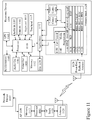
- FIG. 11 there is depicted an electronic device 1104 and network access point 1107 supporting contextual based UIs according to embodiments of the invention.
- Electronic device 1104 may for example be a portable electronic device or a fixed electronic device and may include additional elements above and beyond those described and depicted.
- the protocol architecture is also depicted within the electronic device 1104 that includes an electronic device 1104, such as a smartphone 1055, an access point (AP) 1106, such as first AP 1010, and one or more network devices 1107, such as communication servers, streaming media servers, and routers for example such as first and second servers 1090A and 1090B respectively.
- AP access point
- network devices 1107 such as communication servers, streaming media servers, and routers for example such as first and second servers 1090A and 1090B respectively.
- Network devices 1107 may be coupled to AP 1106 via any combination of networks, wired, wireless and/or optical communication links such as discussed above in respect of Figure 10 .
- the electronic device 1104 includes one or more processors 1110 and a memory 1112 coupled to processor(s) 1110.
- AP 1106 also includes one or more processors 1111 and a memory 1113 coupled to processor(s) 1111.
- a non-exhaustive list of examples for any of processors 1110 and 1111 includes a central processing unit (CPU), a digital signal processor (DSP), a reduced instruction set computer (RISC), a complex instruction set computer (CISC) and the like.
- processors 1110 and 1111 may be part of application specific integrated circuits (ASICs) or may be a part of application specific standard products (ASSPs).
- a non-exhaustive list of examples for memories 1112 and 1113 includes any combination of the following semiconductor devices such as registers, latches, ROM, EEPROM, flash memory devices, non-volatile random access memory devices (NVRAM), SDRAM, DRAM, double data rate (DDR) memory devices, SRAM, universal serial bus (USB) removable memory, and the like.
- Electronic device 1104 may include an audio input element 1114, for example a microphone, and an audio output element 1116, for example, a speaker, coupled to any of processors 1110.
- Electronic device 1104 may include a video input element 1118, for example, a video camera, and a video output element 1120, for example an LCD display, coupled to any of processors 1110.
- Electronic device 1104 also includes a keyboard 1115 and touchpad 1117 which may for example be a physical keyboard and touchpad allowing the user to enter content or select functions within one of more applications 1122. Alternatively the keyboard 1115 and touchpad 1117 may be predetermined regions of a touch sensitive element forming part of the display within the electronic device 1104.
- the one or more applications 1122 that are typically stored in memory 1112 and are executable by any combination of processors 1110.
- Electronic device 1104 also includes accelerometer 1160 providing three-dimensional motion input to the process 1110 and GPS 1162 which provides geographical location information to processor 1110.
- Protocol stack 1124 includes a protocol stack 1124 and AP 1106 includes a communication stack 1125.
- protocol stack 1124 is shown as IEEE 802.11 protocol stack but alternatively may exploit other protocol stacks such as an Internet Engineering Task Force (IETF) multimedia protocol stack for example.
- IETF Internet Engineering Task Force
- AP stack 1125 exploits a protocol stack but is not expanded for clarity. Elements of protocol stack 1124 and AP stack 1125 may be implemented in any combination of software, firmware and/or hardware.
- Protocol stack 1124 includes an IEEE 802.11-compatible PHY module 1126 that is coupled to one or more Front-End Tx/Rx & Antenna 1128, an IEEE 802.11-compatible MAC module 1130 coupled to an IEEE 802.2-compatible LLC module 1132.
- Protocol stack 1124 includes a network layer IP module 1134, a transport layer User Datagram Protocol (UDP) module 1136 and a transport layer Transmission Control Protocol (TCP) module 1138.
- UDP User Datagram Protocol
- TCP Transmission Control Protocol
- Protocol stack 1124 also includes a session layer Real Time Transport Protocol (RTP) module 1140, a Session Announcement Protocol (SAP) module 1142, a Session Initiation Protocol (SIP) module 1144 and a Real Time Streaming Protocol (RTSP) module 1146.
- Protocol stack 1124 includes a presentation layer media negotiation module 1148, a call control module 1150, one or more audio codecs 1152 and one or more video codecs 1154.
- Applications 1122 may be able to create maintain and/or terminate communication sessions with any of devices 1107 by way of AP 1106.
- applications 1122 may activate any of the SAP, SIP, RTSP, media negotiation and call control modules for that purpose.
- information may propagate from the SAP, SIP, RTSP, media negotiation and call control modules to PHY module 1126 through TCP module 1138, IP module 1134, LLC module 1132 and MAC module 1130.
- elements of the electronic device 1104 may also be implemented within the AP 1106 including but not limited to one or more elements of the protocol stack 1124, including for example an IEEE 802.11-compatible PHY module, an IEEE 802.11-compatible MAC module, and an IEEE 802.2-compatible LLC module 1132.
- the AP 1106 may additionally include a network layer IP module, a transport layer User Datagram Protocol (UDP) module and a transport layer Transmission Control Protocol (TCP) module as well as a session layer Real Time Transport Protocol (RTP) module, a Session Announcement Protocol (SAP) module, a Session Initiation Protocol (SIP) module and a Real Time Streaming Protocol (RTSP) module, media negotiation module, and a call control module.
- a network layer IP module a transport layer User Datagram Protocol (UDP) module and a transport layer Transmission Control Protocol (TCP) module
- RTP Real Time Transport Protocol
- SAP Session Announcement Protocol
- SIP Session Initiation Protocol
- RTSP Real Time Streaming Protocol
- Portable and fixed electronic devices represented by electronic device 1104 may include one or more additional wireless or wired interfaces in addition to the depicted IEEE 802.11 interface which may be selected from the group comprising IEEE 802.15, IEEE 802.16, IEEE 802.20, UMTS, GSM 850, GSM 900, GSM 1800, GSM 1900, GPRS, ITU-R 5.138, ITU-R 5.150, ITU-R 5.280, IMT-2000, DSL, Dial-Up, DOCSIS, Ethernet, G.hn, ISDN, MoCA, PON, and Power line communication (PLC).
- PLC Power line communication
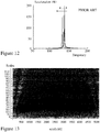
- one common analysis technique is an output only method based upon the Fourier transform method based upon the principal that damage will cause a reduction in stiffness in a given structure, which in turn, will cause a shift in its natural frequency.
- This being commonly referred to as the Fourier Transform Method (FTM) or Natural Frequency Method.
- FTM Fourier Transform Method
- Figure 12 there is presented a graph produced by Wang et al in "A Non-destructive Damage Detection Method for Reinforced Concrete Structures Based on Modal Strain Energy” (University of Technology, Sydney, PhD Thesis, 2010) which demonstrates the shift in natural frequency due to damage of a structure.
- the reference numerals 1 to 4 indicate increasing levels of damage severity.
- Mode Shape Another analysis technique within the prior art is that of Mode Shape (MS) methods that operate under the similar assumption of natural frequency methods in that the presence of damage will produce a measureable difference in the mode shape.
- MS Mode Shape
- the mode shape of the structure can be determined. This is usually done through some sort of forced or natural source of excitation with the use of techniques such as the natural excitation technique (NExT), see for example Yun in "Detection and quantification of structural damage under ambient vibration environment” (Structural Engineering and Mechanics, Vol.
- NTT natural excitation technique
- ERA eigensystem realization algorithm
- SSI stochastic subspace identification
- ⁇ is an N length vector that represents the undamaged mode shape of the mode of the structure and ⁇ * represents the N length vector of the damaged mode shape. If there is a significant difference in the mode shape of one of the segments within the structure, damage has most likely occurred at this location.
- "Significant" damage may be defined for example by Equation (3) where ⁇ ⁇ j signifies the change in mode shape of the j th segment, ⁇ represents the mean value of change in mode shape for the entire beam, and ⁇ is the standard deviation.
- mode shape methods are commonly documented, they are restricted in application as they do not contain a high sensitivity to damage. Often, they are only useful for preliminary rough localization of damage within a structure. For these reasons, application in in-situ structures has been highly limited.
- MSC Mode Shape Curvature
- MSE Modal Strain Energy
- ⁇ j represents the j th component of the MS vector (i.e. the j th discrete segment of the beam) and h j signifies the length of the j th discrete segment of the beam.
- the MSC can be used in place of mode shape in the damage index method discussed in the above section. Doing so has been shown to improve damage localization and reduce noise effects.
- MSC methods also have some of their own disadvantages. For example, a finer mesh measurement points is often required to acquire an accurate depiction of modal curvature. Second, Equation (4) as used to derive the modal shape curvature can introduce errors. This error may become significant if a fine mesh of measurement instruments is not employed.
- Modal Strain Energy (MSE) of a structure is derived from the modal shape curvature can also be used as a damage indicator in the form of fractional strain energy, see for example Stubbs et al. in "Field Verification of a Nondestructive Damage Localization and Severity Estimation Algorithm” (Proc. of IMAC 1995, pp. 210-218 .
- fraction strain energy is given by Equation (5) where i represents the i th mode and all symbols are the same as previous Equations.
- ⁇ T 1.
- n is the total number of discrete segments that the structure has been split up into. Similar to Equation (5) described above the MSE may be used for example as described in Equation (8) to define a threshold for detecting damage to a structure.
- the methods according to embodiments of the invention exploiting wavelet transformation utilize a moving load as an input to an input / output technique. Accordingly, the inventors show that using the acceleration response of a structure to a moving load that it is possible to detect damage using a wavelet transform through a signal processing technique. Beneficially the method does not require any prior knowledge of the healthy state of the structure as with the other methods discussed supra. Accordingly, the Wavelet Transform Method (WTM) removes the requirement compare the intact and damaged states of the structure such as for example where either the difference between the two may be hard to observe or the undamaged state data does not exist such as with older structures, structures that have been repaired and no longer correspond to original design.
- WTM Wavelet Transform Method
- a wavelet is a waveform that has an average value of zero over its duration such as described in Equation (8) where ⁇ ( x ) is a mother wavelet which can be translated and scaled to obtain the analyzing wavelets ⁇ x xs ⁇ as defined by Equation (9) where s is the scaling parameter and x ⁇ represents the translation parameter. Accordingly, the continuous wavelet transform takes the form of Equation (10) where y ( x ) represents the original signal being analyzed and Y ( x, s ) w is the transformed quantity of the signal or the "wavelet coefficient".
- wavelets may be exploited to detect singularities in signals using, for example, the following process. Initially the "mother" wavelet function is compared to a portion of the original time signal, from a device such as an accelerometer. From this comparison, the wavelet coefficient is calculated which is an indicator of how closely the mother wavelet is correlated with the portion of the signal in question. This process is repeated for the entire length of the signal.
- the wavelet is scaled and the process is repeated such that a three-dimensional (3D) surface is created such as is depicted in Figure 13 where the plot represents the wavelength coefficients for a moving load across a 10 meter (approximately 33 feet) long undamaged structure where the position on the horizontal axis represents the location of the moving load and the vertical axis the scale.
- the brightness (intensity) at any point is related to the wavelet coefficient such that higher wavelet coefficients are brighter.
- Higher scales, towards the upper portion of the graph indicate slowly changing features and the coefficients associated correspond to low frequency content whilst lower scales, towards the bottom of the graph, indicate high frequency content.
- FIG. 14 there is depicted a Finite Element (FE) simulation of a moving load traveling across a damaged 10m x 5m x 0.25m (approximately 33' x 16ft x 10") concrete deck as conducted in the ABAQUS Finite Element Analysis software suite. Within the simulation the damage was located a third (1/3) of the length of the beam. The results of this simulation are depicted in Figures 15 and 16 as 3D wavelength coefficient plot and 2D wavelet coefficient plot for scales 300-900 respectively.
- FE Finite Element
- wavelet transforms are particularly useful for detecting singularities within a signal.
- the inventors proposed and have now demonstrated that it is possible to use measurements from an accelerometer to detect damage to a concrete structure both in respect of its existence but also location. Considering a moving load over a concrete structure then there are three response components:
- the method is capable of not only identifying that a structure has damage but also establishing a position along the structure wherein the damage is located. Accordingly, the inventors have extended this to the establishment of the detection of rebar corrosion within a concrete structure. As with the simulations supra these simulations were conducted using the ABAQUS Finite Element Analysis software suite and the wavelet transform was applied to the acceleration response of the structure to a moving load. The parameters for the simulations are given below in Table 1.
- Table 1 Simulation Parameters Size of Concrete Deck 10m long x 5m wide x 0.25m thick Concrete Density 2400 kg/m 3 (approximately 150 lb/ft 3 Concrete Poisson Ratio 0.2 Concrete Young's Modulus 30GPa Concrete Young's Modulus 20,000kg (approximately 44,0001b) Speed of Moving Load 1m/s (approximately 3.6km/h or 2.25mph) Sampling Rate 500Hz Location of Damage 3.33m from left hand side of deck Mother Wavelet Used Bior6.8
- the acceleration response due to moving load from a measurement point 6m away from damage for the two-piece model is displayed for the case wherein the damaged area width was 0.25m. Accordingly, from this acceleration data collected from the measurement point the two dimensional wavelet energy graph can be computed as shown in Figure 20 .
- the corresponding two dimensional wavelet energy graph from the acceleration data of the 0.5m damaged section case is shown in Figure 21 . In addition to the damaged section being identified at the appropriate location in each simulation it can be seen that the magnitude of the peak does not significantly change with damage.
- FIGS 23 through 25 there are depicted two-dimensional wavelet energy plots from measurements points placed at varying distances from damage of 6m, 4m, and 2.25m respectively (approximately 20, 13, and 7 feet respectively).
- Figures 26 through 28 depict the corresponding two-dimensional wavelet energy plots for the same damage - accelerometer configurations but now with the damage width of 0.5m.
- the vertical line indicates the location of damage.
- Figures 20 and 21 and comparing similar separation simulation results such as for example Figures 25 and 28 at 2.25m separation, the height of the wavelet transform coefficients does not substantially change.
- one or more accelerometers appropriately disposed upon or within a structure may provide the required acceleration data, such as that depicted in Figures 19 and 22 .
- This data may then be processed using an automated wavelet transform process on a local or remote computer system to generate the appropriate three-dimensional and two-dimensional wavelet energy plots such as those depicted in respect of Figures 13 , 15 , 16 , 20-21 , and 23-28 respectively which may then be characterised, measured, analysed, stored, and assessed.
- These three-dimensional and two-dimensional plots and results derived therefrom may then be assessed by engineers or automatically characterised.
- the accelerometers may be temporarily disposed upon or within the structure to be assessed or permanently disposed upon or within it.
- a plurality of accelerometers are disposed along the length of a bridge by a technician and an 18-wheeler truck of known weight is then driven at a predetermined speed across the bridge. Such an operation would close the bridge for a short period of time before the bridge was re-opened to traffic.
- the plurality of accelerometers are disposed along the length of a bridge permanently or for an extended period together with a field deployable weigh bridge(s) wherein normal traffic would flow across the bridge with continuous data storage from the accelerometers and weight bridge(s).
- defined discrete events of known load may be identified where the load is the only traffic across the bridge during the measurement allowing these corresponding accelerometer data to be used.
- a structure may be periodically monitored without requiring the deployment of personnel and other resources such as traffic police, police, etc.
- the actual weight of the object may not be an important parameter except that the load moving exceed a predetermined minimum weight and be travelling within a predetermined speed range.
- a load may be characterised at a periodic weigh station and tracked through GPS location based services such that should the load may be correlated temporally and spatially to the event used in the wavelet analysis.
- concrete structures may be assessed in respect of damage through an automated process exploiting moving loads and wavelet transformations / analysis.
- damage may arise from a variety factors including a localized change in concrete parameters as the result of corrosion.
- wavelet transformation analysis it may be beneficial to provide engineers and others with visual information relating to concrete structures.
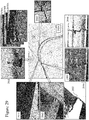
- a Vehicle 2910 is dispatched incorporating a data acquisition system which may, for example, be one or more digital image acquisition systems operating in the normal human visual range but may include others operating, for example, in the near infrared, ultra violet, far infra-red, X-ray and terahertz regions of the electromagnetic spectrum.
- the Vehicle 2910 follows a Route 2920 along one or more roads acquiring a plurality of images from the one or more digital image acquisition systems which are temporally and spatially tagged, e.g. using GPS or another triangulation method such as wireless access points.
- Said digital image acquisition systems may be directed in different directions including towards the road surface, along the highway, angled down towards highway surface, up, to the left, to the right, and angled up away from highway surface. In this manner multiple perspectives may be obtained on damage or other features.
- Vehicle 2910 traverses the route it captures a series of images 2970A...2970N which are then stored together with metadata including, but not limited to, time, location, temperature, weather, and vehicle identity. These may then be associated through geographic data including, but not limited to, mapping data and municipal infrastructure data, to particular elements of infrastructure such as First Image 2930 to "Aviation Parkway East - Highway 417 West Overpass” and “Second Image 2940 to "Cyrville Road - Highway 417 West Overpass.” Images may then be processed using one or more software algorithms in order to isolate, highlight, and classify defects observed within infrastructure elements including, but not limited to, the road surfaces, walls, bridges, overpasses, tunnels, and underpasses.
- Third Image 2960 shows extraction of damaged concrete from an image acquired at coordinates +45° 25' 23.52"N, -75° 37' 5.29"W as well as Fourth Image 2980 at location +45° 25' 21.43"N, - 75° 37' 25.26”W.
- damage may be assessed with improved accuracy as to impact.
- a crack within the road surface such as that within Fourth Image 2980 may in some instances when observed on the road surface of a concrete bridge for example be merely surface damage whilst in another instance the surface damage may be correlated to a location of damage within the structure from the WTM analysis.
- the images are processed to highlight features such as depicted in Fifth and Sixth Images 2950 and 2960 respectively wherein digital image processing has been used to remove image content and accentuate the damaged region(s) within the image.
- Fifth Image 2950 a combination of image processing and edge detection have been employed to yield highlight 2955 wherein in Sixth Image 2990 only image processing has been employed. It would be evident that in some embodiments of the invention these images may be obtained using infrared imaging, or other non-visible ranges, in combination with or in isolation of visual images.
- the spectral characteristics of the overlaying concrete, asphalt etc., layers to the underlying base and sub-base materials may be exploited with or without illumination to determine whether damage has penetrated different depths and accordingly have different priorities and / or repair requirements. For example, a large number of shallow damage sections may have a lower priority than a single deep damaged section that has exposed the rebars within the structure or has propagated through the highway surface for example.
- FIG. 30 there is depicted a Network 1000 supporting communications to and from electronic devices acquiring, storing, analysis, and presenting data relating to infrastructure characteristics such as damage according to embodiments of the invention.
- the overall structure in Figure 30 is similar to that shown in Figure 10 except that also connected to Network 1000 is Vehicle 3090 which may, for example, be one performing the mapping of infrastructure such as described in respect of Figure 29 and accordingly the acquired image data may be transmitted continuously and / or periodically through Network 1000 for storage / analysis / assessment / archiving etc.
- Vehicle 3090 may be the vehicle providing the moving input to the structure in respect of Figures 13 through 28 described above and the WTM method of determining the location of damage.
- Vehicle 3090 may in this instance simply transmit data such as velocity, location, and time to the Network 1000 for storage / analysis / assessment / archiving in combination with the data acquired from the one or more Accelerometers 3010A which may be deployed permanently or temporarily upon the structure.
- Accelerometers 3010A With low cost integrated circuit accelerometers exploiting silicon microelectromechanical structures (MEMS) these may be packaged to provide low cost permanently deployed accelerometers such as Accelerometers 3010A. Accordingly, in some embodiments of the invention the Accelerometers 3010A may contain only short-range wireless communications and be powered through solar cells such that they only communicate their data to the Vehicle 3090 when it is within range periodically or aperiodically. Vehicle 3090 then may combine this data together with that it acquires regarding location, speed, time, etc. to provide a combined record of a structure characterization.
- MEMS silicon microelectromechanical structures
- a truck configured to be essentially loaded over one axle may be driven around the highways and automatically acquire data for each bridge it travels over whilst one or more police vehicles may be employed to stop and hold traffic for a short period of time whilst the Vehicle 3090 traverses the structure.
- data acquired and / or acquired relating to infrastructure damage and / or integrity may be connected to a communications network such as Network 1000 either continuously or intermittently and accordi77ngly stored, analysed, retrieved etc.
- a communications network such as Network 1000 either continuously or intermittently and accordi77ngly stored, analysed, retrieved etc.
- the infrastructure damage and / or integrity together with the analysis of the measurements and their mapping may be triggered as a result of activities triggered by, for example, the Government Body 3060A and / or State Body 3070 in order to address regulatory requirements, safety concerns etc.
- the data collection for automated inspection, monitoring, and regulatory compliance / management of concrete structures may include, in addition to the features described and discussed elsewhere within this specification, features such as:
- the processing of images acquired for automated inspection, monitoring, and regulatory compliance / management of concrete structures may include, in addition to the features described and discussed elsewhere within this specification, features such as:
- Automatic alarm notification related to the status of a bridge by comparing the growth of crack or increase in size of spalling or rust stains between various inspections, which have been time stamped by the portable / mobile data collection system and have known scale to define a limit at which the alarm is triggered or define multiple limits at which different alarms are triggered.
- a first alarm may be triggered notifying the infrastructure owner that an issue requires addressing whilst a second alarm may be triggered if the detected defect has not been addressed on a subsequent measurement or the determined defect requires that other action be taken requiring regulatory / Government input and / or action.
- a small crack may require a municipality repair it whilst a large crack may require a State / Provincial regulatory and / or control body to limit traffic, axle weight, etc. until further analysis and / or correction is performed.
- a smart signage system may be controlled via an application installed upon a PED such as that within the portable / mobile data collection system or that belonging to the inspector.
- a system according to an embodiment of the invention may combine optical image techniques together with other sensors such as those counting the number of vehicles that have passed e.g. through laser based systems, surface deployed pressure tube systems, and / or image processing.
- a single inspector may establish and manage a traffic flow / control system either prior to or during operation of a portable / mobile data collection system for example to acquire the required data. Further such a system may determine the presence of an articulated tractor trailer, establish the identity of the tractor trailer through pattern recognition / feature extraction of the registration, control the traffic such that the truck passes on its own, capture data during the tractor trailer crossing the bridge, for example, and transmit the data to remote server(s) for processing via wavelet analysis such as described supra wherein the tractor trailer data is employed to cross reference load weigh station data for the loading of the tractor trailer.
- the automated system does not perform such a controlled roll of the tractor trailer over the concrete structure.
- a portable / mobile data collection system may operate in conjunction with head mounted display and / or vision augmentation devices, e.g. Google Glass, on drones either remote-controlled or programmed, for example, for a path of inspection around a suspension bridge, as well as on robots for inspection of tunnels, pipelines to provide an operator / inspector with eyewear-assisted or remote-vision applications and features for visual inspection as well as providing communication with non-destructive testing probes, systems, etc.
- the operator / inspector may, for example, be presented with an overlay of the infra-red imaging with their view so that they may, for example, associate elements within both as they view them.
- Such associations from an inspector may be logged, analysed and used as part of learning networks / algorithms to improve the determination / classification of damage observed subsequently.
- a half-cell requires that electrical connections be made from the electrical voltmeter / multimeter to the half-cell reference electrode and rebar.
- this electrical connection requirement is removed.
- sensors on the rebar and surface of the concrete are linked to one another or to a portable / mobile data collection system or a remote server.
- a wireless link couples the sensor on the rebar to a sensor coupled to the concrete incorporating a half-cell, such as half-cell 310B.
- an embodiment of the invention may exploit one or more additional half-cells including, but not limited to, aqueous reference electrodes (e.g. standard and / or normal hydrogen electrode, palladium-hydrogen, etc.), non-aqueous reference electrodes, pseudo-reference electrodes, and quasi-reference electrodes.
- aqueous reference electrodes e.g. standard and / or normal hydrogen electrode, palladium-hydrogen, etc.
- non-aqueous reference electrodes e.g. standard and / or normal hydrogen electrode, palladium-hydrogen, etc.
- pseudo-reference electrodes e.g. standard and / or normal hydrogen electrode, palladium-hydrogen, etc.
- images taken by smartphone or tablet forming part of a portable / mobile data collection system wherein, for example, a laser based grid may be projected onto the concrete surface from a laser based generator attached to the smartphone, tablet, and / or system capturing the image and / or a laser based system attached to the smartphone, tablet, and / or system capturing the image of the concrete surface so that the scale and distance may be determined automatically based upon the known characteristics of the camera and the optical pointing devices.
- Such a laser assisted scaling and distance determination is required as the dimensions of objects in optical two-dimensional (2D) images cannot be easily determined without having additional information about the third dimension of the image.
- One technique to reconstruct a three-dimensional (3D) image of a scene is to use two cameras looking at the scene from two slightly different angles or as described supra in respect of an embodiment of the invention exploit a single camera with electro-optic switch to sequentially capture the two different angles. This technique is known as stereo vision and is currently used in many products and applications but suffers in that it requires extensive post-processing and computation effort.
- the inventors obtain the dimensional information as well as distance from the camera to a scene from the 2D image by reflecting at least 3 laser points from the scene.
- Figure 32 which also depicts the principle of transforming to determine scale and distance according to an embodiment of the invention. Accordingly, in this embodiment with three laser points parallel to each other wherein the beams of these three laser points are reflected on the scene object. As the three lasers are affixed to the PED and / or portable / mobile data collection system then the distances between these points at the source are known and constant.
- Equation (12) For each point x P y P in the image then we have a point in the image plane in the Cartesian coordinate x n y n as determined by Equation (12) wherein M 3 ⁇ 3 is a 3 ⁇ 3 conversion matrix that be defined by the specification of the camera, such as its focal length, and can be defined through a calibration process. Accordingly, x P and y P are in pixels such that x n and y n are defined by Equations (13A) and (13B) respectively where X n , Y n , Z n are the world coordinates of the point in the Cartesian coordinate system.
- x P y P 1 M 3 ⁇ 3 ⁇ x n y n 1
- Equation (14) we have coordinates as defined in Equations (14A) to (14C) wherein we can find x 1 , x 2 , x 3 , y 1 , y 2 , y 3 from Equation (14) using the locations of the laser points on the image.
- the goal is to determine the values for X 1 , Y 1 , Z 1 , X 2 , Y 2 ,Z 2 , X 3 , Y 3 , Z 3 which provide the real world coordinates of the laser points on the object.
- Equations (15A) to (15C) are correct.
- x 1 X 1 Z 1
- y 1 Y 1 Z 1
- x 2 X 2 Z 2
- y 2 Y 2 Z 2
- x 3 X 3 Z 3
- Equations (16A) to (16C) provide three equations for the three unknown parameters that can be solved numerically or analytically. Using Equations (14A) to (14C) can also be determined. As a result, the equation of a plane passing through the three laser points can be obtained knowing their Cartesian coordinates, Equation (17) and then the distance between any two points (Point A and Point B) on this plane can be determined from pixel distance between two points on the image as given by Equations (18A) to (19).
- Equation (17) Equation (21) from which and accordingly and can be calculated.
- the parameter Z 3 provides us the distance from the camera to the object, and X n , ,and Z 3 data of those two points can be used to measure the distance between the two points.
- images acquired by an_portable / mobile data collection system may be defined by a scale allowing measurements of defects, cracks, spalling, etc. as well as allowing the scaling of multiple images to be performed for a combining process to generate larger views of the concrete structure, etc. as well as stitching sequential images or images acquired over a period of time.
- first and second images 3100A and 3100B respectively with respect to a non-contact electrical characterization of corrosion and rebar presence within concrete according to an embodiment of the invention.
- first image 3100A of Figure 31 the electrical response of rebar inside the concrete is determined from the surface of the concrete with four probes without an electrical connection to the rebar within the concrete.
- four probes 3160A to 3160D in an electrical configuration similar to that of a prior art 4-point Wenner probe in that the outer pair of probes 3160A and 3160D respectively apply a signal and the inner pair of probes 3160B and 3160C measure the resulting potential difference between them via voltmeter 3130.
- the signal applied across the outer pair of probes 3160A to 3160D is an AC signal, typically at 40Hz
- the inventors have replaced this with a DC current source 3120.
- a 4-point Wenner probe wherein all probes are equally spaced, or a 4-point Schlumberger probe, wherein the spacing of the outer probes from the inner probes is equal but different to the separation of the inner probes, is employed to measure the electrical resistivity of concrete.
- rebar(s) within the concrete can disturb the electrical resistivity measurements and accordingly the recommended measurement orientation of the 4-point Wenner / Schlumberger probes is determined by the spacing of the rebars as ideally the orientation is diagonal to the square matrix of rebars but if this not possible then the orientation should be perpendicular to the rebar.
- these orientations and spacings are at best approximate and generally assumed relative to the portion of the concrete structure being measured.
- the inventors have established the ability to determine the presence of a rebar and / or its corrosion state based upon the temporal evolution of polarization resistance determined from the measured signals as indicated in second image 3100B in Figure 31 .
- second image 3100B it can be seen that for non-corroded rebar the evolution of the normalized polarization resistance is positive and the ratio after even only a couple of seconds is greater for rebars that are closer to the surface of the concrete.
- the slope for a corroded rebar is close to zero for the same depth of rebar and also reduced in percentage deviation.
- a reference measurement of polarization resistance ratio in the absence of rebar within concrete is also depicted with a small negative slope.
- R P ( t )/ R P 0 the relative polarization resistance of the reinforced concrete system, measured from the surface of concrete changes with time and depends upon the location and diameter of the rebar in the concrete as well as its corrosion condition, i.e. presence, severity and rate of corrosion.
- R P ( t )/ R P 0 increases for non-corroding rebar.
- R P ( t )/ R P 0 does not change significantly, and in fact is almost constant with no significant change.
- This method according to embodiments of the invention is also applicable to various types of rebar including, but not limited to, epoxy-coated rebar, stainless steel rebar, and galvanized steel rebar.
- this method is sensitive to the direction of rebars crossing each other. By changing the direction of the probe with respect to the reinforcement mesh then the measurement can detect the condition of only the rebar parallel to the direction of the measurement.
- the DC 4-probe technique can be used initially to verify that the thickness of concrete over the rebar within a new concrete structure meets the design requirements as the magnitude of R P ( t )/ R P 0 for uncorroded rebar increases with decreasing rebar depth.
- the condition of initial rebars is acceptable post concrete pour and subsequently be used to monitor the status of rebars within concrete structures directly and isolate the condition of the rebars in each direction discretely.
- first to third images 3100C to 3100D respectively a handheld non-contact corrosion detector instrument according to an embodiment of the invention.
- first image 3100C different electrical characteristics of the reinforced concrete system can be extracted using a 6-point probe established by the inventors.
- a pair of measurement contacts allow measurement of a voltage, V , to the concrete surface wherein the measurements are made by a first pair of excitation contacts aligned at 45° to the inner contacts and a second pair of excitation contacts aligned at - 45° to the inner contacts such that the first and second pairs of excitation contacts are orthogonal to each other and offset at 45° relative to the inner contacts.
- a prototype instrument of such configuration is depicted in third image 3100E.
- the inventors have established an instrument that allows the corrosion measurements on rebars along the X and Y directions to be performed separately. Also in this design, we use only two inner probes for the voltage measurement in both directions. Using this arrangement, only the direction of applied current or voltage on the external electrodes will be switched between the X and Y directions. In the other words, the same inner probes are used for the voltage measurement for both directions modified based on the 4-probe method.
- a portable / mobile data collection system has been primarily described with respect to a vehicle, e.g. a car, van, truck, articulated truck, tractor-trailer, etc.
- a portable / mobile data collection system may also be configured in other embodiments of the invention(s) to be mounted to a motorcycle, cycle, cart, golf buggy, etc. as well as a backpack, body pack, etc. for use by an individual.
- FIG. 33 there is depicted a concrete assessment assembly (CONCAA) 3300A there is depicted an embodiment of such a test configuration.
- the CONCAA 3300A comprises a tube 3340 having internal diameter of 150mm (6"), for example, and depth of 300mm (12").
- This tube 3340 is disposed within a structure prior to pouring with rods 3330 mounted within holder 3320 that fits onto the upper surface of the tube 3340. As such during the pour the concrete wells up within the tube 3340 surrounding the rods 3330.
- a tester 3310 is fitted to the upper exposed portions of the rods 3330 and retained in position with nuts on the threaded rods 3330.
- the tester 3310 then monitors the electrical parameters of the circuit formed between itself, the pair of rods 3330 and the concrete which is now curing.
- the recorded data from the tester 3310 can be retrieved, for example, wirelessly via a PED such as depicted in image 3300B.
- the tester 3310 can be removed and a protective cap applied to the CONCAA 3300A. This may be determined from a protocol established in dependence upon the electrical characteristic evolution such as described and depicted supra in respect of Figures 4 to 9B respectively.
- the testers 3310 can then be applied to a subsequent pour and / or be repositioned periodically to perform ongoing concrete assessment.
- the test engineer visits the site, for example, places the testers 3310 onto the CONCAA 3300A for a predetermined period of time before the measurements are retrieved from the testers 3310 and employed to define the properties of the concrete.
- This as depicted in Figure 33 be via a wireless interrogation of the tester 3310 but it may alternatively be via a wired connection such that the reader, e.g. a smartphone or tablet, is connected to the CONCAA 3300A via a cable and connector or optical communications link.
- the tagging of the embedded sensors may include, but not be limited to, information such as batch identity, truck identity, date, time, location, batch mix parameters, etc. but also importantly information such as the maturity calibration curves for the mix established by the manufacturer. Accordingly, depending upon the degree of complexity embedded into the embedded sensor such data may be either retrieved for remote storage and subsequent use or it may be part of the embedded sensors processing of electrical measurement data such that calibration data of the concrete mix is already factored into the data provided by the embedded sensors. Accordingly, the embedded sensors, such as prototype 3460 and production concept form 3470 may be added to the concrete at the batching point 3410 either tagged already or tagged during loading. Subsequently upon delivery and pouring 3420 the embedded sensors may be read for information regarding the delivery process etc.
- the embedded sensors may be read for curing information 3430 and then subsequently, depending upon the battery - power consumption etc., periodically read for lifetime data 3440 of the concrete.
- the acquired data may be acquired wirelessly and then pushed through network 1000 to one or more servers 3490.
- the embedded sensors may be executing a software application which presents to the user concrete parameter data either as provided from the embedded sensor(s) directly using the calibration curves stored within or upon the device using calibration curve data stored within the embedded sensor but not processed by it, stored within the device or retrieved from the data stored upon the remote server 3490.
- prototype sensor 3460 is enabled when an electrical circuit is completed via the flying leads.
- the sensor may be enabled through a wireless signal, a vibration exceeding a threshold, via an electrical circuit being completed, etc.
- the embodiments of the invention support tagging the sensors and embedding the maturity calibration curves in the sensor. These curves are mix-specific and depending on the temperature history of the concrete can be used to estimate the strength of concrete. By embedded them within the sensors and the sensors employing this data the concrete manufacturer does not need to release commercially sensitive information such as their proprietary mix and calibration curves.
- step 3505 a batch of concrete is prepared wherein in step 3510 the calibration data, for example the maturity calibration curves, is generated for that batch.
- step 3515 this calibration data is stored within a batch of sensors which will be embedded with the concrete mix.
- step 3520 additional data such as date, time, location, delivery identity, order data, manufacturer identity, etc.
- the now embedded sensors monitor the concrete during the delivery - transportation sequence in step 3330 wherein at the site the current data is retrieved from the embedded sensors in step 3535 wherein this is employed to establish current concrete condition and projected cure in step 3540 wherein a delivery accept / reject decision is made in step 3545 wherein a rejection leads to step 3550 otherwise the process proceeds to step 3555 wherein the concrete is poured on site and the embedded sensors continue monitoring.
- step 3560 the data from the sensors is retrieved either in a single retrieval event or multiple events such that in step 3565 the concrete condition, projected cure, projected strength, etc. are established.
- step 3570 a decision on the concrete pour is made as to whether it will be allowed to continue curing or whether there is a problem and remedial work / tear-down etc. are required at which the process proceeds to step 3575 and terminates or proceeds to step 3580.
- step 3580 the embedded sensors continue monitoring the concrete but now for longer term characteristics as the cure has been passed at step 3570. Subsequently the embedded sensor data is acquired in step 3585 and used in step 3590 to establish the concrete's condition. If everything is within defined boundaries then the process proceeds from a decision step 3595A to loop otherwise it proceeds to step 3595B and an alarm is triggered with respect to the condition of the concrete. In this manner the life cycle of the concrete can be tracked with the embedded sensors.
- the embedded sensors may be amended to an increased period between sampling points wherein, for example, after a first predetermined period (e.g. 1 week) the sampling drops to a lower rate, then again at predetermined points either time based or concrete cure derived such that, for example, sampling drops to hourly, daily etc. to provide extended battery life.
- a first predetermined period e.g. 1 week
- the embedded sensors may be designed for specific short life cycle for the initial portion of the concrete life cycle after which other methods are employed such as described supra in respect of Figures 31A and 31B for example.
- data regarding the curing of a concrete structure throughout its structure may be derived rather than from a limited number of sampling points or concrete tests on delivered concrete.
- the number of embedded sensors may be established as 1 per cubic meter, 1 per 2 cubic meter, 1 per 8 cubic meter, 4 per truck irrespective of load, etc.
- the number may be varied in accordance with concrete mix, architect schedule so that sensitive load bearing structures are more accurately plotted than others.
- Embedded sensors may be formed from a variety of materials include, but not limited, to metals, ceramics, plastics, resins, and rubbers according to the requirements for compatibility with the concrete, lifetime, crush resistance etc.
- the embedded sensors may be hollow or solid with cavities for electronics / battery etc.
- the embedded sensor may comprise a plurality of metallic elements isolated with respect to each other to form electrical connections between the electronics within the embedded sensor and the concrete.
- Implementation of the techniques, blocks, steps and means described above may be done in various ways. For example, these techniques, blocks, steps and means may be implemented in hardware, software, or a combination thereof.
- the processing units may be implemented within one or more application specific integrated circuits (ASICs), digital signal processors (DSPs), digital signal processing devices (DSPDs), programmable logic devices (PLDs), field programmable gate arrays (FPGAs), processors, controllers, micro-controllers, microprocessors, other electronic units designed to perform the functions described above and/or a combination thereof.
- ASICs application specific integrated circuits
- DSPs digital signal processors
- DSPDs digital signal processing devices
- PLDs programmable logic devices
- FPGAs field programmable gate arrays
- processors controllers, micro-controllers, microprocessors, other electronic units designed to perform the functions described above and/or a combination thereof.
- the embodiments may be described as a process which is depicted as a flowchart, a flow diagram, a data flow diagram, a structure diagram, or a block diagram. Although a flowchart may describe the operations as a sequential process, many of the operations can be performed in parallel or concurrently. In addition, the order of the operations may be rearranged.
- a process is terminated when its operations are completed, but could have additional steps not included in the figure.
- a process may correspond to a method, a function, a procedure, a subroutine, a subprogram, etc. When a process corresponds to a function, its termination corresponds to a return of the function to the calling function or the main function.
- embodiments may be implemented by hardware, software, scripting languages, firmware, middleware, microcode, hardware description languages and/or any combination thereof.
- the program code or code segments to perform the necessary tasks may be stored in a machine readable medium, such as a storage medium.
- a code segment or machine-executable instruction may represent a procedure, a function, a subprogram, a program, a routine, a subroutine, a module, a software package, a script, a class, or any combination of instructions, data structures and/or program statements.
- a code segment may be coupled to another code segment or a hardware circuit by passing and/or receiving information, data, arguments, parameters and/or memory contents. Information, arguments, parameters, data, etc. may be passed, forwarded, or transmitted via any suitable means including memory sharing, message passing, token passing, network transmission, etc.
- the methodologies may be implemented with modules (e.g., procedures, functions, and so on) that perform the functions described herein.
- Any machine-readable medium tangibly embodying instructions may be used in implementing the methodologies described herein.
- software codes may be stored in a memory.
- Memory may be implemented within the processor or external to the processor and may vary in implementation where the memory is employed in storing software codes for subsequent execution to that when the memory is employed in executing the software codes.
- the term "memory" refers to any type of long term, short term, volatile, nonvolatile, or other storage medium and is not to be limited to any particular type of memory or number of memories, or type of media upon which memory is stored.
- the term “storage medium” may represent one or more devices for storing data, including read only memory (ROM), random access memory (RAM), magnetic RAM, core memory, magnetic disk storage mediums, optical storage mediums, flash memory devices and/or other machine readable mediums for storing information.
- ROM read only memory
- RAM random access memory
- magnetic RAM magnetic RAM
- core memory magnetic disk storage mediums
- optical storage mediums flash memory devices and/or other machine readable mediums for storing information.
- machine-readable medium includes, but is not limited to portable or fixed storage devices, optical storage devices, wireless channels and/or various other mediums capable of storing, containing or carrying instruction(s) and/or data.
- the methodologies described herein are, in one or more embodiments, performable by a machine which includes one or more processors that accept code segments containing instructions. For any of the methods described herein, when the instructions are executed by the machine, the machine performs the method. Any machine capable of executing a set of instructions (sequential or otherwise) that specify actions to be taken by that machine are included.
- a typical machine may be exemplified by a typical processing system that includes one or more processors.
- Each processor may include one or more of a CPU, a graphics-processing unit, and a programmable DSP unit.
- the processing system further may include a memory subsystem including main RAM and/or a static RAM, and/or ROM.
- a bus subsystem may be included for communicating between the components.
- the processing system requires a display, such a display may be included, e.g., a liquid crystal display (LCD).
- a display e.g., a liquid crystal display (LCD).
- the processing system also includes an input device such as one or more of an alphanumeric input unit such as a keyboard, a pointing control device such as a mouse, and so forth.
- the memory includes machine-readable code segments (e.g. software or software code) including instructions for performing, when executed by the processing system, one of more of the methods described herein.
- the software may reside entirely in the memory, or may also reside, completely or at least partially, within the RAM and/or within the processor during execution thereof by the computer system.
- the memory and the processor also constitute a system comprising machine-readable code.
- the machine operates as a standalone device or may be connected, e.g., networked to other machines, in a networked deployment, the machine may operate in the capacity of a server or a client machine in server-client network environment, or as a peer machine in a peer-to-peer or distributed network environment.
- the machine may be, for example, a computer, a server, a cluster of servers, a cluster of computers, a web appliance, a distributed computing environment, a cloud computing environment, or any machine capable of executing a set of instructions (sequential or otherwise) that specify actions to be taken by that machine.
- the term "machine” may also be taken to include any collection of machines that individually or jointly execute a set (or multiple sets) of instructions to perform any one or more of the methodologies discussed herein.
- the specification may have presented the method and/or process of the present invention as a particular sequence of steps. However, to the extent that the method or process does not rely on the particular order of steps set forth herein, the method or process should not be limited to the particular sequence of steps described. As one of ordinary skill in the art would appreciate, other sequences of steps may be possible. Therefore, the particular order of the steps set forth in the specification should not be construed as limitations on the claims. In addition, the claims directed to the method and/or process of the present invention should not be limited to the performance of their steps in the order written, and one skilled in the art can readily appreciate that the sequences may be varied and still remain within the scope of the present invention.
Applications Claiming Priority (3)
| Application Number | Priority Date | Filing Date | Title |
|---|---|---|---|
| US201461992364P | 2014-05-13 | 2014-05-13 | |
| PCT/CA2015/000314 WO2015172231A1 (fr) | 2014-05-13 | 2015-05-13 | Procédés et systèmes électriques pour essais sur béton |
| EP15792644.5A EP3143387B1 (fr) | 2014-05-13 | 2015-05-13 | Procédés et systèmes électriques pour essais sur béton |
Related Parent Applications (1)
| Application Number | Title | Priority Date | Filing Date |
|---|---|---|---|
| EP15792644.5A Division EP3143387B1 (fr) | 2014-05-13 | 2015-05-13 | Procédés et systèmes électriques pour essais sur béton |
Publications (1)
| Publication Number | Publication Date |
|---|---|
| EP3869187A1 true EP3869187A1 (fr) | 2021-08-25 |
Family
ID=54479075
Family Applications (2)
| Application Number | Title | Priority Date | Filing Date |
|---|---|---|---|
| EP15792644.5A Active EP3143387B1 (fr) | 2014-05-13 | 2015-05-13 | Procédés et systèmes électriques pour essais sur béton |
| EP20213926.7A Pending EP3869187A1 (fr) | 2014-05-13 | 2015-05-13 | Procédés et systèmes électriques pour essais sur béton |
Family Applications Before (1)
| Application Number | Title | Priority Date | Filing Date |
|---|---|---|---|
| EP15792644.5A Active EP3143387B1 (fr) | 2014-05-13 | 2015-05-13 | Procédés et systèmes électriques pour essais sur béton |
Country Status (4)
| Country | Link |
|---|---|
| US (2) | US10775332B2 (fr) |
| EP (2) | EP3143387B1 (fr) |
| CA (4) | CA2948912C (fr) |
| WO (1) | WO2015172231A1 (fr) |
Families Citing this family (47)
| Publication number | Priority date | Publication date | Assignee | Title |
|---|---|---|---|---|
| US9389191B2 (en) * | 2012-10-22 | 2016-07-12 | Troxler Electronic Laboratories, Inc. | Conveyor system and measuring device for determining water content of a construction material |
| US10768130B2 (en) | 2013-01-30 | 2020-09-08 | Giatec Scientific Inc. | Method and systems relating to construction material assessment |
| US9638652B2 (en) | 2013-01-30 | 2017-05-02 | Giatec Scientific Inc. | Electrical methods and systems for concrete testing |
| CN105408898B (zh) * | 2013-03-15 | 2019-05-28 | 弗兰克公司 | 测量数据的自动记录和图形生成 |
| CA2948912C (fr) | 2014-05-13 | 2022-01-04 | Giatec Scientific Ltd. | Procedes et systemes electriques pour essais sur beton |
| US10719727B2 (en) * | 2014-10-01 | 2020-07-21 | Apple Inc. | Method and system for determining at least one property related to at least part of a real environment |
| WO2016189896A1 (fr) * | 2015-05-22 | 2016-12-01 | 富士フイルム株式会社 | Robot et procédé de commande de mouvement pour robot |
| WO2017090426A1 (fr) * | 2015-11-27 | 2017-06-01 | 富士フイルム株式会社 | Dispositif de mesure d'objet physique et procédé de mesure d'objet physique |
| EP3387417A1 (fr) | 2015-12-07 | 2018-10-17 | Structural Health Systems, Inc. | Procédé et système de surveillance d'éléments de construction de bâtiments |
| US20170238073A1 (en) * | 2016-02-16 | 2017-08-17 | Premiere Concrete Solutions, LLC | Concrete Maturity System |
| CA2962684C (fr) * | 2016-03-30 | 2020-12-22 | Pouria Ghods | Capteurs de surveillance sans fil integres |
| CN105973554B (zh) * | 2016-05-13 | 2018-04-03 | 河海大学 | 一种抗噪的使用振型检测梁类结构损伤的方法 |
| WO2018005460A1 (fr) * | 2016-06-27 | 2018-01-04 | Quipip, Llc | Dispositif de détection, et systèmes et procédés d'obtention de données relatives aux mélanges de béton et aux structures en béton |
| WO2018035124A1 (fr) * | 2016-08-17 | 2018-02-22 | Quipip, Llc | Dispositif de détection, et systèmes et procédés d'obtention de données se rapportant aux mélanges de béton et aux structures en béton |
| CN106290485B (zh) * | 2016-09-12 | 2019-07-26 | 深圳大学 | 一种水泥基材料干燥深度测试方法 |
| CN212181161U (zh) * | 2016-12-30 | 2020-12-18 | 高途乐公司 | 可穿戴成像设备 |
| WO2018129483A1 (fr) | 2017-01-08 | 2018-07-12 | Troxler Electronic Laboratories, Inc. | Appareil, procédé et système associé permettant de tester un échantillon de matériau de chaussée |
| JP7032722B2 (ja) * | 2017-07-14 | 2022-03-09 | 国立研究開発法人産業技術総合研究所 | 鉄筋コンクリートの鉄筋腐食評価方法 |
| EP3435246A1 (fr) * | 2017-07-24 | 2019-01-30 | Tata Consultancy Services Limited | Système et procédé d'analyse de signaux |
| US10317905B2 (en) * | 2017-08-10 | 2019-06-11 | RavenOPS, Inc. | Autonomous robotic technologies for industrial inspection |
| US11061041B1 (en) | 2017-10-05 | 2021-07-13 | Forney, L.P. | System, method, and apparatus for verifiable materials testing |
| CN107860796B (zh) * | 2017-12-07 | 2023-04-14 | 中国人民解放军陆军勤务学院 | 一种用于监测混凝土质量和凝结硬化状态的方法 |
| DE102017012068A1 (de) * | 2017-12-29 | 2019-07-04 | Imko Micromodultechnik Gmbh | Verfahren zur Überprüfung der Konsistenz eines gelieferten Betons bzw. einer gelieferten Charge eines Betons |
| US20200363392A1 (en) * | 2018-02-07 | 2020-11-19 | Porous Technologies, Llc | Smart porous concrete slab |
| US20190188811A1 (en) | 2018-02-17 | 2019-06-20 | Constru Ltd | System and method for generating financial assessments based on construction site images |
| US10228360B2 (en) * | 2018-02-18 | 2019-03-12 | Constru Ltd | System and method for determining the quality of concrete |
| US11055841B2 (en) * | 2018-02-18 | 2021-07-06 | Constru Ltd | System and method for determining the quality of concrete from construction site images |
| ES2724808A1 (es) * | 2018-03-09 | 2019-09-16 | Innovating 4M S L | Dispositivo y procedimiento para la determinacion de la resistencia a compresion del hormigon |
| US10783623B2 (en) * | 2018-12-03 | 2020-09-22 | Mistras Group, Inc. | Systems and methods for inspecting pipelines using a robotic imaging system |
| US11143599B2 (en) | 2018-12-03 | 2021-10-12 | Mistras Group, Inc. | Systems and methods for inspecting pipelines using a pipeline inspection robot |
| US10890505B2 (en) * | 2018-12-03 | 2021-01-12 | Mistras Group, Inc. | Systems and methods for inspecting pipelines using a robotic imaging system |
| CN109269879B (zh) * | 2018-12-04 | 2024-01-30 | 深圳万测试验设备有限公司 | 一种智能混凝土压力试验装置 |
| JP7329951B2 (ja) * | 2019-04-01 | 2023-08-21 | キヤノン株式会社 | 画像処理装置およびその制御方法 |
| WO2020198872A1 (fr) | 2019-04-03 | 2020-10-08 | Pouria Ghods | Dispositifs de capteur intégré et procédés |
| US11680198B2 (en) | 2019-09-13 | 2023-06-20 | Saudi Arabian Oil Company | Water swellable cement sheath on demand, with sensing capability |
| IT201900022941A1 (it) * | 2019-12-10 | 2021-06-10 | Matera Inerti S R L | Dispositivo intelligente e metodo per il monitoraggio tramite l’internet delle cose del calcestruzzo |
| IT201900024592A1 (it) * | 2019-12-24 | 2021-06-24 | Matera Inerti S R L | Dispositivo intelligente e relativo metodo orientato all'ispezione in tempo reale delle condizioni di integrità del calcestruzzo e dei materiali per le costruzioni |
| US11698323B2 (en) * | 2020-03-17 | 2023-07-11 | Palo Alto Research Center Incorporated | Methods and system for determining a control load using statistical analysis |
| US11326876B1 (en) | 2020-03-25 | 2022-05-10 | Fdh Infrastucture Services, Llc | Systems and methods for estimating concrete thickness |
| CN112285136B (zh) * | 2020-10-15 | 2023-01-10 | 国网天津市电力公司 | 即时追踪混凝土二维吸水过程的x射线测量方法 |
| CN112464534B (zh) * | 2020-11-27 | 2023-07-18 | 四川石油天然气建设工程有限责任公司 | 油气管悬索跨越仿真分析模型及其构建方法 |
| CN113324895B (zh) * | 2021-05-26 | 2024-03-01 | 武汉科思特仪器股份有限公司 | 不锈钢耐腐蚀性快速检测装置及方法 |
| CN114065517B (zh) * | 2021-11-16 | 2023-03-10 | 深圳大学 | 一种采用新型模型无损预测混凝土耐久性能的方法与系统 |
| CN114279937B (zh) * | 2021-12-29 | 2023-07-25 | 山东交通学院 | 一种混凝土结构抗渗透性能无损检测装置 |
| CN114264589B (zh) * | 2021-12-29 | 2023-07-04 | 山东交通学院 | 用于现场环境的混凝土抗氯离子渗透性检测装置及方法 |
| CN115719017B (zh) * | 2022-11-21 | 2023-07-18 | 深圳大学 | 海水海砂混凝土多物理场耦合分析及施工质量控制方法 |
| CN116625827B (zh) * | 2023-06-17 | 2024-01-23 | 广州市盛通建设工程质量检测有限公司 | 含钢渣细集料的混凝土抗压测试方法、装置、设备及介质 |
Citations (4)
| Publication number | Priority date | Publication date | Assignee | Title |
|---|---|---|---|---|
| US20020154029A1 (en) * | 1999-02-26 | 2002-10-24 | Sri International | Sensor devices for structural health monitoring |
| US20050210995A1 (en) * | 2004-02-26 | 2005-09-29 | Drnevich Vincent P | Method and apparatus for measuring properties of concrete |
| US20070090945A1 (en) * | 2005-10-20 | 2007-04-26 | Hoogenboom Christopher L | Power conserving mode for a sensor for monitoring the structural integrity of a building |
| JP2013106192A (ja) * | 2011-11-14 | 2013-05-30 | Aisin Seiki Co Ltd | 携帯端末用ホルダ |
Family Cites Families (12)
| Publication number | Priority date | Publication date | Assignee | Title |
|---|---|---|---|---|
| US3468001A (en) | 1967-07-24 | 1969-09-23 | Bodine Albert G | Apparatus including an orbiting-mass sonic oscillator for slip-forming concrete |
| IL134799A (en) | 2000-02-29 | 2003-07-31 | Concretec Ltd | Methods and apparatus for non-destructive control and forecasting concrete strength |
| US6690182B2 (en) * | 2000-07-19 | 2004-02-10 | Virginia Technologies, Inc | Embeddable corrosion monitoring-instrument for steel reinforced structures |
| US6950767B2 (en) * | 2002-11-15 | 2005-09-27 | Renesas Technology Corp. | Quality monitoring system for building structure, quality monitoring method for building structure and semiconductor integrated circuit device |
| US7181978B2 (en) | 2003-11-14 | 2007-02-27 | Concretec Ltd. | Method, apparatus and system for forecasting strength of cementitious material |
| US7225682B2 (en) | 2004-06-22 | 2007-06-05 | Concretec Ltd. | Method, apparatus and system for monitoring hardening and forecasting strength of cementitious material |
| US8610444B2 (en) | 2010-04-14 | 2013-12-17 | Concretec Ltd. | Method and system for analyzing a chemically-active material |
| US9169158B2 (en) * | 2010-04-16 | 2015-10-27 | Cidra Corporate Services Inc. | Non-chemical air entrained admix |
| US8766641B2 (en) * | 2012-08-28 | 2014-07-01 | Halliburton Energy Services, Inc. | Determining surface wetting of rock with changing well fluids |
| US9429559B2 (en) * | 2014-01-29 | 2016-08-30 | Quipip, Llc | Systems, methods and apparatus for obtaining data relating to condition and performance of concrete mixtures |
| CA2948912C (fr) | 2014-05-13 | 2022-01-04 | Giatec Scientific Ltd. | Procedes et systemes electriques pour essais sur beton |
| US10101288B2 (en) * | 2014-08-28 | 2018-10-16 | William N. Carr | Wireless impedance spectrometer |
-
2015
- 2015-05-13 CA CA2948912A patent/CA2948912C/fr active Active
- 2015-05-13 US US15/311,055 patent/US10775332B2/en active Active
- 2015-05-13 WO PCT/CA2015/000314 patent/WO2015172231A1/fr active Application Filing
- 2015-05-13 CA CA3185962A patent/CA3185962A1/fr active Pending
- 2015-05-13 CA CA3122674A patent/CA3122674C/fr active Active
- 2015-05-13 CA CA3125171A patent/CA3125171C/fr active Active
- 2015-05-13 EP EP15792644.5A patent/EP3143387B1/fr active Active
- 2015-05-13 EP EP20213926.7A patent/EP3869187A1/fr active Pending
-
2020
- 2020-09-14 US US17/019,578 patent/US11531000B2/en active Active
Patent Citations (4)
| Publication number | Priority date | Publication date | Assignee | Title |
|---|---|---|---|---|
| US20020154029A1 (en) * | 1999-02-26 | 2002-10-24 | Sri International | Sensor devices for structural health monitoring |
| US20050210995A1 (en) * | 2004-02-26 | 2005-09-29 | Drnevich Vincent P | Method and apparatus for measuring properties of concrete |
| US20070090945A1 (en) * | 2005-10-20 | 2007-04-26 | Hoogenboom Christopher L | Power conserving mode for a sensor for monitoring the structural integrity of a building |
| JP2013106192A (ja) * | 2011-11-14 | 2013-05-30 | Aisin Seiki Co Ltd | 携帯端末用ホルダ |
Non-Patent Citations (7)
| Title |
|---|
| FAN ET AL.: "Vibration-based Damage Identification Methods: A Review and Comparative Study", STRUCTURAL HEALTH MONITORING, vol. 10, no. 1, pages 83 - 111 |
| MCCARTER W J ET AL: "Dependence of electrical impedance of cement-based materials on their moisture condition", JOURNAL OF PHYSICS D: APPLIED PHYSICS, INSTITUTE OF PHYSICS PUBLISHING LTD, GB, vol. 22, no. 11, 14 November 1989 (1989-11-14), pages 1773 - 1776, XP020014911, ISSN: 0022-3727, DOI: 10.1088/0022-3727/22/11/033 * |
| STUBBS ET AL.: "Field Verification of a Nondestructive Damage Localization and Severity Estimation Algorithm", PROC. OF IMAC, 1995, pages 210 - 218 |
| UBERTINI ET AL.: "Automated modal identification in operational conditions and its application to bridges", ENGINEERING STRUCTURES, vol. 46, pages 264 - 278 |
| W BRAMESHUBER ET AL: "Non-Destructive Determination of the Water-Content in the Concrete Cover Using the Multiring-Electrode", INTERNATIONAL SYMPOSIUM FOR NON-DESTRUCTIVE TESTING IN CIVIL ENGINEERING, vol. 8, 10, 16 September 2003 (2003-09-16), pages 1 - 6, XP055343545 * |
| WANG ET AL.: "PhD Thesis", 2010, UNIVERSITY OF TECHNOLOGY, article "A Non-destructive Damage Detection Method for Reinforced Concrete Structures Based on Modal Strain Energy" |
| YUN: "Detection and quantification of structural damage under ambient vibration environment", STRUCTURAL ENGINEERING AND MECHANICS, vol. 42, no. 3, pages 425 - 448 |
Also Published As
| Publication number | Publication date |
|---|---|
| CA3122674C (fr) | 2023-03-07 |
| CA3125171A1 (fr) | 2015-11-19 |
| US11531000B2 (en) | 2022-12-20 |
| US20200408707A1 (en) | 2020-12-31 |
| EP3143387A1 (fr) | 2017-03-22 |
| CA3185962A1 (fr) | 2015-11-19 |
| CA2948912C (fr) | 2022-01-04 |
| US20170108456A1 (en) | 2017-04-20 |
| EP3143387A4 (fr) | 2017-04-05 |
| WO2015172231A1 (fr) | 2015-11-19 |
| EP3143387B1 (fr) | 2020-12-16 |
| US10775332B2 (en) | 2020-09-15 |
| CA2948912A1 (fr) | 2015-11-19 |
| CA3125171C (fr) | 2023-03-07 |
| CA3122674A1 (fr) | 2015-11-19 |
Similar Documents
| Publication | Publication Date | Title |
|---|---|---|
| US11531000B2 (en) | Electrical methods and systems for concrete testing | |
| US11454606B2 (en) | Method and systems relating to construction material assessment | |
| US11549899B2 (en) | Electrical methods and systems for concrete testing | |
| US20210063336A1 (en) | Construction material assessment method and systems | |
| US9436783B2 (en) | Method and system for estimating degradation and durability of concrete structures and asset management system making use of same | |
| Chen | Laser scanning technology for bridge monitoring | |
| Bernhard et al. | An interdisciplinary effort to develop a wireless embedded sensor system to monitor and assess corrosion in the tendons of prestressed concrete girders | |
| Alamdari et al. | Non-contact structural health monitoring of a cable-stayed bridge: Case study | |
| Soleymani et al. | Damage detection and monitoring in heritage masonry structures: Systematic review | |
| US20230184707A1 (en) | Electrical methods and systems for concrete testing | |
| Ha et al. | Monitoring concrete compressive strength using IoT-based wireless sensor network | |
| Acero Molina et al. | Comparing the Accuracy between UAS Photogrammetry and LiDAR in Bridge Inspections | |
| Yuan et al. | Survey and Monitoring Methods for Masonry Arches and Vaults | |
| Al Shaini | The Use of Point Cloud Data to Support Concrete Bridge Deck Condition Assessment | |
| Taresh et al. | Investigation of short-range sensing devices for use in nondestructive pavement evaluation | |
| Al Shehyari et al. | Use of Laser scanning, Remote Sensors & Traffic Data Collection, Drones & Mobile Application. MoEI Federal Highways network case study | |
| LIN | BUILDING CONCRETE STRUCTURE ASSESSMENT USING IMAGE-BASED NON-DESTRUCTIVE TECHNIQUE | |
| Gucunski et al. | ANDERS: future of concrete bridge deck evaluation and rehabilitation | |
| JP2021189615A (ja) | 土木構造物の非破壊検査システム | |
| Aktan et al. | Research on non-destructive evaluation: workshop. |
Legal Events
| Date | Code | Title | Description |
|---|---|---|---|
| PUAI | Public reference made under article 153(3) epc to a published international application that has entered the european phase |
Free format text: ORIGINAL CODE: 0009012 |
|
| STAA | Information on the status of an ep patent application or granted ep patent |
Free format text: STATUS: THE APPLICATION HAS BEEN PUBLISHED |
|
| AC | Divisional application: reference to earlier application |
Ref document number: 3143387 Country of ref document: EP Kind code of ref document: P |
|
| AK | Designated contracting states |
Kind code of ref document: A1 Designated state(s): AL AT BE BG CH CY CZ DE DK EE ES FI FR GB GR HR HU IE IS IT LI LT LU LV MC MK MT NL NO PL PT RO RS SE SI SK SM TR |
|
| STAA | Information on the status of an ep patent application or granted ep patent |
Free format text: STATUS: REQUEST FOR EXAMINATION WAS MADE |
|
| 17P | Request for examination filed |
Effective date: 20220214 |
|
| RBV | Designated contracting states (corrected) |
Designated state(s): AL AT BE BG CH CY CZ DE DK EE ES FI FR GB GR HR HU IE IS IT LI LT LU LV MC MK MT NL NO PL PT RO RS SE SI SK SM TR |
|
| P01 | Opt-out of the competence of the unified patent court (upc) registered |
Effective date: 20230523 |
|
| STAA | Information on the status of an ep patent application or granted ep patent |
Free format text: STATUS: EXAMINATION IS IN PROGRESS |
|
| 17Q | First examination report despatched |
Effective date: 20231130 |