EP3868898B1 - Machine for finishing hides - Google Patents
Machine for finishing hides Download PDFInfo
- Publication number
- EP3868898B1 EP3868898B1 EP21155427.4A EP21155427A EP3868898B1 EP 3868898 B1 EP3868898 B1 EP 3868898B1 EP 21155427 A EP21155427 A EP 21155427A EP 3868898 B1 EP3868898 B1 EP 3868898B1
- Authority
- EP
- European Patent Office
- Prior art keywords
- roller
- machine
- belt
- rubber
- hides
- Prior art date
- Legal status (The legal status is an assumption and is not a legal conclusion. Google has not performed a legal analysis and makes no representation as to the accuracy of the status listed.)
- Active
Links
Images


Classifications
-
- C—CHEMISTRY; METALLURGY
- C14—SKINS; HIDES; PELTS; LEATHER
- C14B—MECHANICAL TREATMENT OR PROCESSING OF SKINS, HIDES OR LEATHER IN GENERAL; PELT-SHEARING MACHINES; INTESTINE-SPLITTING MACHINES
- C14B1/00—Manufacture of leather; Machines or devices therefor
- C14B1/44—Mechanical treatment of leather surfaces
- C14B1/56—Ornamenting, producing designs, embossing
-
- C—CHEMISTRY; METALLURGY
- C14—SKINS; HIDES; PELTS; LEATHER
- C14B—MECHANICAL TREATMENT OR PROCESSING OF SKINS, HIDES OR LEATHER IN GENERAL; PELT-SHEARING MACHINES; INTESTINE-SPLITTING MACHINES
- C14B1/00—Manufacture of leather; Machines or devices therefor
- C14B1/28—Machines for treating leather combined with devices for measuring and printing
-
- C—CHEMISTRY; METALLURGY
- C14—SKINS; HIDES; PELTS; LEATHER
- C14B—MECHANICAL TREATMENT OR PROCESSING OF SKINS, HIDES OR LEATHER IN GENERAL; PELT-SHEARING MACHINES; INTESTINE-SPLITTING MACHINES
- C14B17/00—Details of apparatus or machines for manufacturing or treating skins, hides, leather, or furs
- C14B17/06—Work feeding or clamping devices
-
- C—CHEMISTRY; METALLURGY
- C14—SKINS; HIDES; PELTS; LEATHER
- C14B—MECHANICAL TREATMENT OR PROCESSING OF SKINS, HIDES OR LEATHER IN GENERAL; PELT-SHEARING MACHINES; INTESTINE-SPLITTING MACHINES
- C14B7/00—Special leathers and their manufacture
- C14B7/06—Leather webs built up of interengaged strips or pieces, e.g. by braiding
-
- C—CHEMISTRY; METALLURGY
- C14—SKINS; HIDES; PELTS; LEATHER
- C14C—CHEMICAL TREATMENT OF HIDES, SKINS OR LEATHER, e.g. TANNING, IMPREGNATING, FINISHING; APPARATUS THEREFOR; COMPOSITIONS FOR TANNING
- C14C15/00—Apparatus for chemical treatment or washing of hides, skins, or leather
-
- B—PERFORMING OPERATIONS; TRANSPORTING
- B05—SPRAYING OR ATOMISING IN GENERAL; APPLYING FLUENT MATERIALS TO SURFACES, IN GENERAL
- B05C—APPARATUS FOR APPLYING FLUENT MATERIALS TO SURFACES, IN GENERAL
- B05C1/00—Apparatus in which liquid or other fluent material is applied to the surface of the work by contact with a member carrying the liquid or other fluent material, e.g. a porous member loaded with a liquid to be applied as a coating
- B05C1/04—Apparatus in which liquid or other fluent material is applied to the surface of the work by contact with a member carrying the liquid or other fluent material, e.g. a porous member loaded with a liquid to be applied as a coating for applying liquid or other fluent material to work of indefinite length
- B05C1/08—Apparatus in which liquid or other fluent material is applied to the surface of the work by contact with a member carrying the liquid or other fluent material, e.g. a porous member loaded with a liquid to be applied as a coating for applying liquid or other fluent material to work of indefinite length using a roller or other rotating member which contacts the work along a generating line
- B05C1/0808—Details thereof, e.g. surface characteristics
-
- B—PERFORMING OPERATIONS; TRANSPORTING
- B05—SPRAYING OR ATOMISING IN GENERAL; APPLYING FLUENT MATERIALS TO SURFACES, IN GENERAL
- B05C—APPARATUS FOR APPLYING FLUENT MATERIALS TO SURFACES, IN GENERAL
- B05C1/00—Apparatus in which liquid or other fluent material is applied to the surface of the work by contact with a member carrying the liquid or other fluent material, e.g. a porous member loaded with a liquid to be applied as a coating
- B05C1/04—Apparatus in which liquid or other fluent material is applied to the surface of the work by contact with a member carrying the liquid or other fluent material, e.g. a porous member loaded with a liquid to be applied as a coating for applying liquid or other fluent material to work of indefinite length
- B05C1/08—Apparatus in which liquid or other fluent material is applied to the surface of the work by contact with a member carrying the liquid or other fluent material, e.g. a porous member loaded with a liquid to be applied as a coating for applying liquid or other fluent material to work of indefinite length using a roller or other rotating member which contacts the work along a generating line
- B05C1/0817—Apparatus in which liquid or other fluent material is applied to the surface of the work by contact with a member carrying the liquid or other fluent material, e.g. a porous member loaded with a liquid to be applied as a coating for applying liquid or other fluent material to work of indefinite length using a roller or other rotating member which contacts the work along a generating line characterised by means for removing partially liquid or other fluent material from the roller, e.g. scrapers
-
- B—PERFORMING OPERATIONS; TRANSPORTING
- B05—SPRAYING OR ATOMISING IN GENERAL; APPLYING FLUENT MATERIALS TO SURFACES, IN GENERAL
- B05C—APPARATUS FOR APPLYING FLUENT MATERIALS TO SURFACES, IN GENERAL
- B05C1/00—Apparatus in which liquid or other fluent material is applied to the surface of the work by contact with a member carrying the liquid or other fluent material, e.g. a porous member loaded with a liquid to be applied as a coating
- B05C1/04—Apparatus in which liquid or other fluent material is applied to the surface of the work by contact with a member carrying the liquid or other fluent material, e.g. a porous member loaded with a liquid to be applied as a coating for applying liquid or other fluent material to work of indefinite length
- B05C1/08—Apparatus in which liquid or other fluent material is applied to the surface of the work by contact with a member carrying the liquid or other fluent material, e.g. a porous member loaded with a liquid to be applied as a coating for applying liquid or other fluent material to work of indefinite length using a roller or other rotating member which contacts the work along a generating line
- B05C1/0826—Apparatus in which liquid or other fluent material is applied to the surface of the work by contact with a member carrying the liquid or other fluent material, e.g. a porous member loaded with a liquid to be applied as a coating for applying liquid or other fluent material to work of indefinite length using a roller or other rotating member which contacts the work along a generating line the work being a web or sheets
- B05C1/083—Apparatus in which liquid or other fluent material is applied to the surface of the work by contact with a member carrying the liquid or other fluent material, e.g. a porous member loaded with a liquid to be applied as a coating for applying liquid or other fluent material to work of indefinite length using a roller or other rotating member which contacts the work along a generating line the work being a web or sheets being passed between the coating roller and one or more backing rollers
-
- B—PERFORMING OPERATIONS; TRANSPORTING
- B05—SPRAYING OR ATOMISING IN GENERAL; APPLYING FLUENT MATERIALS TO SURFACES, IN GENERAL
- B05C—APPARATUS FOR APPLYING FLUENT MATERIALS TO SURFACES, IN GENERAL
- B05C1/00—Apparatus in which liquid or other fluent material is applied to the surface of the work by contact with a member carrying the liquid or other fluent material, e.g. a porous member loaded with a liquid to be applied as a coating
- B05C1/04—Apparatus in which liquid or other fluent material is applied to the surface of the work by contact with a member carrying the liquid or other fluent material, e.g. a porous member loaded with a liquid to be applied as a coating for applying liquid or other fluent material to work of indefinite length
- B05C1/08—Apparatus in which liquid or other fluent material is applied to the surface of the work by contact with a member carrying the liquid or other fluent material, e.g. a porous member loaded with a liquid to be applied as a coating for applying liquid or other fluent material to work of indefinite length using a roller or other rotating member which contacts the work along a generating line
- B05C1/0856—Reverse coating rollers
Definitions
- the present invention relates to a machine for finishing hides, according to the general part of claim 1.
- FIG. 1 A machine for finishing hides of a known type is shown in Figure 1 .
- roller machines are used, commonly known as coating machines, in which the hides P are transported by a rubber belt 1 and pressed against an opposite engraved roller 2, which deposits onto the surface of the hide an even film of liquid L, previously spread out on said engraved roller by one or more blades 9.
- the engraved roller can rotate in "synchro", that is in the same direction as the direction of advancement of the hide or in "reverse”, that is in the direction opposite to the aforesaid direction of the hide.
- the perfect success of the hide finishing operation depends on many factors, among which the predominant ones are a regular entry of the hide into the restricted zone, that is the one included between the engraved roller and the underlying roller or conveyor belt and a well determined compression force of the portion of hide which comes into contact, in a substantially tangent manner with the surface of the aforesaid engraved roller.
- the uniformity of this compression force when the roller coating machine is equipped with a conveyor rubber belt 1 depends on the tension of the belt itself to ensure the winding thereof on the first roller 4, acting as a contrast medium inside said rubber belt 1 mentioned above and opposite to the engraved roller 2.
- a hide detaching roller 17 is provided, actually consisting of a cylindrical element with a modest toothing, which rotates in the same direction with respect to the second return roller and therefore with peripheral speeds of the proximal zones of these two rollers having opposite directions. Said hide detaching roller facilitates the detachment of the hide from the rubber belt and its delivery to the next transport element for the drying step.
- Another measure to facilitate the detachment of the hides from the conveyor belt consists in providing a second roller with a diameter as small as possible.
- the outer surface of the belt at the second roller with an extremely small diameter is necessarily destined to expand longitudinally; consequently, due to said longitudinal expansion of the belt, a sliding between the meat side of the hide and said belt is created, facilitating the detachment of said hide from the belt itself.
- this reduction in the diameter of the second roller also causes an intrinsic mechanical weakness of said roller which tends to flex excessively, since the belt must necessarily be stretched to be moved, with an unacceptable flexibility of the roller, especially at its central part.
- rollers which are not perfectly cylindrical, but are slightly convex at their central part, so as to compensate for the longitudinal flexibility of the roller.
- the roller has a common angular speed at the whole of its development, but a peripheral speed which is greater at the zones with a greater radius. This entails the fact that, at the central zone, the roller slides on the inner part of the belt with unacceptable vibrations and wear of the belt itself. Therefore, this measure is also rarely used.
- Object of the present invention is to realise a machine for finishing hides of the type described above which is capable of obviating the drawbacks manifested by similar products of known type.
- object of the invention is to realise a machine for finishing hides capable, in particular, of delivering the hides to the subsequent transport devices for the drying step without minimally soiling said hides, in particular at their meat side.
- Further object of the invention is to provide a machine of this type, which is simple from the constructive point of view, practical and safer for the operator.
- the second roller is equipped with at least one supporting element that is integral with the machine frame; in particular, said supporting element is positioned between the ends of said second roller to increase stiffness thereof with respect to the longitudinal flexibility.
- a machine for finishing hides of known type provides that a hide P is adduced by opposite belts 10, 11, which define a conveying channel 12, to a zone in which there is a rubber conveyor belt 1 as well as an engraved roller 2, which presses against the aforesaid, which deposits onto the surface of said hide P an even film of liquid L, previously spread out on said engraved roller by one or more blades 9.
- the belt 1 is towed by a first roller 4 and returned by a second roller 5.
- the hide is deposited on a subsequent conveyor means 6, in most cases consisting in fact of a suitable belt.
- rollers 4 and 5 are a drive roller, while the other one is an idle roller and in particular the roller 4 is a drive roller and the roller 5 is an idle roller; suitable washing and drying means 3 are also provided, which operate continuously on the outer surface of the belt 1 of the machine. All this constitutes a prior art and therefore a state of the art of the present invention.
- a suitable hide detaching roller 17 which, as already said previously, is constituted by a cylindrical element with a modest toothing which rotates in the same direction both with respect to the second roller 5 and to a roller 18 which moves the conveyor means 6 constituted, in most cases, by a suitable belt.
- the second roller 5 is in particular provided with a supporting element 13 that is integral with the machine frame, positioned between the ends of said second roller 5 to increase stiffness thereof with respect to the longitudinal flexibility.
- this supporting element is integral with a rod 14 that is parallel to the second roller 5, which is in turn hinged upon an element 15 integral with the machine fixed frame.
- said second roller 5 is hinged upon said element 15.
- Figures 8 and 9 also highlight the above; in particular, it is clearly evident that it is possible to configure a single removable supporting frame with respect to the machine, so as to ease assembling/disassembling operations, as already stated above.
- the machine according to the invention can comprise more return rollers, and among them it can provide an idle roller 8 (see in particular Figure 2 ) which has means adapted to change positioning thereof; based on said positioning, said roller 8 is in particular adapted to modify the point of contact of the rubber belt 1 with the overlying engraved roller 2.
- the ratio between the diameter of the first roller 4 and the diameter of the second roller 5 is equal to or greater than 5.
- the belt 1 is made of rubber, which advantageously has a hardness lower than 40 Shore A. It is also possible to provide for one or more layers of artificial or natural elements to be present on the inner surface of the rubber. Finally, it is advantageously provided that the rubber belt 1 has a thickness Sp of the rubber portion, variable from 8 to 25 mm.
- a plurality of supporting elements 13 is provided; as shown in these figures, they are arranged equally spaced apart between the ends of the second roller 5.
- the device according to the invention is able to meet the objects previously proposed, thanks to the fact that the at least one supporting element 13 present at the second roller 5 is able to clearly obviate the flexibility of the roller 5.
Landscapes
- Engineering & Computer Science (AREA)
- Chemical & Material Sciences (AREA)
- Organic Chemistry (AREA)
- Manufacturing & Machinery (AREA)
- Mechanical Engineering (AREA)
- Chemical Kinetics & Catalysis (AREA)
- General Chemical & Material Sciences (AREA)
- Rollers For Roller Conveyors For Transfer (AREA)
- Treatment And Processing Of Natural Fur Or Leather (AREA)
Description
- The present invention relates to a machine for finishing hides, according to the general part of
claim 1. - A machine for finishing hides of a known type is shown in
Figure 1 . - As is known, for carrying out the finishing operation in the tannery field, in particular, roller machines are used, commonly known as coating machines, in which the hides P are transported by a
rubber belt 1 and pressed against an opposite engravedroller 2, which deposits onto the surface of the hide an even film of liquid L, previously spread out on said engraved roller by one or more blades 9. - The engraved roller can rotate in "synchro", that is in the same direction as the direction of advancement of the hide or in "reverse", that is in the direction opposite to the aforesaid direction of the hide.
- The perfect success of the hide finishing operation depends on many factors, among which the predominant ones are a regular entry of the hide into the restricted zone, that is the one included between the engraved roller and the underlying roller or conveyor belt and a well determined compression force of the portion of hide which comes into contact, in a substantially tangent manner with the surface of the aforesaid engraved roller. The uniformity of this compression force when the roller coating machine is equipped with a
conveyor rubber belt 1 depends on the tension of the belt itself to ensure the winding thereof on thefirst roller 4, acting as a contrast medium inside saidrubber belt 1 mentioned above and opposite to the engravedroller 2. - The publication
EP 0997538 , which is the most important document of the state of the art, describes a machine for finishing hides which, thanks to its configuration, is able to operate also on soft hides. - The publication
EP3599289 A2 describes a machine for finishing hides in which a roller supported by particular supporting elements is provided. However, also this machine does not allow to achieve the objects that will be better explained hereinafter. Other documents of the state of the art are:KR 101151279 B1 DE 4101003 A1 . In any case, the hides having a thin thickness tend to adhere to the conveyor belt and a device is therefore necessary which allows an easy detachment thereof for the delivery to a further transport means for the drying step. - In the present coating machines, a hide detaching
roller 17 is provided, actually consisting of a cylindrical element with a modest toothing, which rotates in the same direction with respect to the second return roller and therefore with peripheral speeds of the proximal zones of these two rollers having opposite directions. Said hide detaching roller facilitates the detachment of the hide from the rubber belt and its delivery to the next transport element for the drying step. - Unfortunately, it must be considered that during the finishing step the grain side of the hide is wetted with specific liquid products suitable for said finishing. Such liquid products obviously tend to fall both on the edge of the hides and, with the passage of time, to accumulate also on the outer surface of the conveyor belt; therefore it necessarily happens that the hide detaching roller tends to become soiled with such liquid products, both because of the contact with the edge of the already finished hides and, due to its proximity, with the conveyor belt.
- In practice, given the absolute proximity between the belt and the hide detaching roller, an indirect passage of liquid chemical finishing product takes place between the belt and said hide detaching roller.
- It must be considered that this is somehow acceptable in certain processes in which it is not particularly important that the meat side of the hides is somehow soiled or contaminated with liquid chemical finishing product. This is the case, for example, of hides having some type of lining or the like, at the meat side. However, there is currently a greater tendency to use hides at both their faces. In these cases, it is therefore totally unacceptable to have any type of contamination of liquid chemical finishing product, even minimal, at the meat side of the hides. Therefore, in the presence of thin and soft hides, it is not possible to use such type of finishing machines and this operation is carried out with spraying machines which are structurally different from those described above.
- Another measure to facilitate the detachment of the hides from the conveyor belt consists in providing a second roller with a diameter as small as possible. In this way, the outer surface of the belt at the second roller with an extremely small diameter is necessarily destined to expand longitudinally; consequently, due to said longitudinal expansion of the belt, a sliding between the meat side of the hide and said belt is created, facilitating the detachment of said hide from the belt itself. However, this reduction in the diameter of the second roller also causes an intrinsic mechanical weakness of said roller which tends to flex excessively, since the belt must necessarily be stretched to be moved, with an unacceptable flexibility of the roller, especially at its central part.
- In order to try to overcome this drawback, it has also been attempted to use rollers which are not perfectly cylindrical, but are slightly convex at their central part, so as to compensate for the longitudinal flexibility of the roller.
- However, it must be considered that, obviously, the roller has a common angular speed at the whole of its development, but a peripheral speed which is greater at the zones with a greater radius. This entails the fact that, at the central zone, the roller slides on the inner part of the belt with unacceptable vibrations and wear of the belt itself. Therefore, this measure is also rarely used.
- In practice, with such constructive method, as visible in
Figure 6 , which relates to the invention but with elements also present in the state of the art, once the diameter of thesecond roller 5 has been defined by D and the thickness of the conveyor belt has been defined by Sp, the ratio between the outer fake circumference travelled by the outer surface of the belt and the inner fake circumference travelled by the inner surface of the belt is equal to
- Object of the present invention is to realise a machine for finishing hides of the type described above which is capable of obviating the drawbacks manifested by similar products of known type.
- Specifically, object of the invention is to realise a machine for finishing hides capable, in particular, of delivering the hides to the subsequent transport devices for the drying step without minimally soiling said hides, in particular at their meat side.
- Further object of the invention is to provide a machine of this type, which is simple from the constructive point of view, practical and safer for the operator.
- This is achieved, according to the invention, by providing that the second roller is equipped with at least one supporting element that is integral with the machine frame; in particular, said supporting element is positioned between the ends of said second roller to increase stiffness thereof with respect to the longitudinal flexibility.
- The present invention will now be illustrated and described in detail with reference to some of its possible embodiments, given only by way of non-limiting example, with the aid of the accompanying drawings, in which;
-
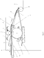
fig. 1 shows a schematic view of a machine for finishing hides of a known type, according to the state of the art; -
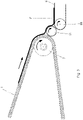
fig. 2 shows a corresponding view of the machine for finishing hides, according to the invention; -
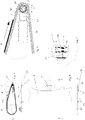
fig. 3 shows a side view of the detail of the zone where the hide is delivered in a machine for finishing hides, both according to the state of the art and according to the invention, to the transport element for the drying step; -
figs. 4 and 5 show respectively a top plan view and a side view of the machine for finishing hides, according to the invention; -
figs. 6 and 7 show details of the machine at the second roller of the hide, according to the invention; -
figs. 8 and 9 show, respectively, an overall view and a detail of the fundamental elements of the device according to the invention, in a first particular embodiment thereof; -
figs. 10 and 11 show, respectively, an overall view and a detail of the fundamental elements of the device according to the invention, in a second particular embodiment thereof. - As shown in
Figure 1 , a machine for finishing hides of known type provides that a hide P is adduced byopposite belts channel 12, to a zone in which there is arubber conveyor belt 1 as well as an engravedroller 2, which presses against the aforesaid, which deposits onto the surface of said hide P an even film of liquid L, previously spread out on said engraved roller by one or more blades 9. Thebelt 1 is towed by afirst roller 4 and returned by asecond roller 5. At saidsecond roller 5 the hide is deposited on a subsequent conveyor means 6, in most cases consisting in fact of a suitable belt. Actually, one of therollers roller 4 is a drive roller and theroller 5 is an idle roller; suitable washing anddrying means 3 are also provided, which operate continuously on the outer surface of thebelt 1 of the machine. All this constitutes a prior art and therefore a state of the art of the present invention. - Always according to the state of the art, in order to facilitate the transfer of the hide P from the
belt 1 to a conveyor means 6, a suitable hide detachingroller 17 is provided which, as already said previously, is constituted by a cylindrical element with a modest toothing which rotates in the same direction both with respect to thesecond roller 5 and to aroller 18 which moves the conveyor means 6 constituted, in most cases, by a suitable belt. - With reference to
Figures 4 to 7 , according to the invention, it can be seen that thesecond roller 5 is in particular provided with a supportingelement 13 that is integral with the machine frame, positioned between the ends of saidsecond roller 5 to increase stiffness thereof with respect to the longitudinal flexibility. - From the operating point of view, this supporting element is integral with a
rod 14 that is parallel to thesecond roller 5, which is in turn hinged upon anelement 15 integral with the machine fixed frame. In particular, saidsecond roller 5 is hinged upon saidelement 15. In this way it is therefore evident that, thanks to the presence of the supportingelement 13, the longitudinal flexibility of theroller 5 is greatly reduced, which allows to solve the problem constituted by the drawbacks manifested by similar products of known type (state of the art). - According to the invention, it is possible to ensure that the supporting frame of the
second return roller 5, shown in particular inFigures 4 and 5 , is in fact removable with respect to the assembly of the machine according to the invention, so as to ease assembling/disassembling operations. - As shown in particular in
Figure 7 , in order to allow thesecond roller 5 to operate with the supportingelement 13, the presence ofbearings 16 is provided, advantageously of the rolling type, arranged around thecylindrical core 19 of thesecond roller 5, so as to allow the rotation of thecylindrical core 19 with respect to the supportingelement 13. From this figure it can be seen that saidcylindrical core 19 is hinged at its ends to aplate 20, integral with therod 14. -
Figures 8 and 9 also highlight the above; in particular, it is clearly evident that it is possible to configure a single removable supporting frame with respect to the machine, so as to ease assembling/disassembling operations, as already stated above. - The machine according to the invention can comprise more return rollers, and among them it can provide an idle roller 8 (see in particular
Figure 2 ) which has means adapted to change positioning thereof; based on said positioning, saidroller 8 is in particular adapted to modify the point of contact of therubber belt 1 with the overlying engravedroller 2. - To ensure the winding of the
rubber belt 1 on thefirst roller 4 opposite to the engravedroller 2, in order to exert the minimum useful tension necessary to guarantee the compression force of the portion of hide which comes into contact with the aforesaid engraved roller, it is advantageous that the ratio between the diameter of thefirst roller 4 and the diameter of thesecond roller 5 is equal to or greater than 5. - From the operating point of view, the
belt 1 is made of rubber, which advantageously has a hardness lower than 40 Shore A. It is also possible to provide for one or more layers of artificial or natural elements to be present on the inner surface of the rubber. Finally, it is advantageously provided that therubber belt 1 has a thickness Sp of the rubber portion, variable from 8 to 25 mm. - With reference to
Figures 10 and 11 , it can be seen that, according to a further embodiment of the device according to the invention, a plurality of supportingelements 13 is provided; as shown in these figures, they are arranged equally spaced apart between the ends of thesecond roller 5. - From the above description it can therefore be seen how the device according to the invention is able to meet the objects previously proposed, thanks to the fact that the at least one supporting
element 13 present at thesecond roller 5 is able to clearly obviate the flexibility of theroller 5. - It should also be noted that the present invention may assume shapes and aspects other than those illustrated and described above, without prejudice to its essential characteristics, as defined in the following claims.
Claims (13)
- MACHINE FOR FINISHING HIDES, in which hides are conveyed by a rubber belt(1) and pressed against an opposite engraved roller (2), which deposits onto the surface of the hide (P) an even film of liquid (L), previously spread out on said engraved roller(2) by one or more blades (9), said belt (1) being towed by a first roller (4) and returned by a second roller (5), at which the hide is deposited on a subsequent conveyor means (6), one of said first and second rollers (4, 5) being a drive roller and the other being an idle roller,
said machine being characterized in that the second roller (5) is provided with at least a supporting element (13) that is integral with a fixed machine frame and positioned between the two ends of said second roller (5) to increase stiffness thereof with respect to the longitudinal flexibility. - MACHINE, according to claim 1, characterized in that it is provided with washing and drying means (3) which operate continuously on the outer surface of the machine belt.
- MACHINE, according to one or more of the preceding claims, characterized in that it provides a plurality of return rollers.
- MACHINE, according to one or more of the preceding claims, characterized in that it provides a plurality of supporting elements (13) arranged equally spaced apart between the ends of the second roller (5).
- MACHINE, according to one or more of the preceding claims, characterized in that the at least one supporting element is integral with a rod (14) that is parallel to the second roller (5), which is in turn hinged upon an element (15) integral with the machine fixed frame, said second roller (5) being hinged upon said element (15).
- MACHINE, according to one or more of the preceding claims, characterized in that the first roller (4) is a drive roller, while the second roller (5) is an idle roller.
- MACHINE, according to one or more of the preceding claims, characterized in that the first roller (4) is an idle roller, while the second roller (5) is a drive roller.
- MACHINE, according to one or more of the preceding claims, characterized in that the ratio between the first roller (4) diameter and the second roller (5) diameter is equal to or higher than 5.
- MACHINE, according to one or more of the preceding claims, characterized in that on the inner surface of the rubber belt (1) an idle roller (8) operates, which has means adapted to change positioning thereof, said roller (8), based on said positioning, being adapted to modify the contact point of the rubber belt (1) with the overlying engraved roller (2).
- MACHINE, according to one or more of the preceding claims, characterized in that the return roller (5) is assembled on a supporting frame that is removable with respect to the machine so as to ease assembling/disassembling operations.
- MACHINE, according to one or more of the preceding claims, characterized in that the belt (1) is made of rubber, having hardness lower than 40 Shore A.
- MACHINE, according to one or more of the preceding claims, characterized in that one or more layers of artificial or natural elements are present on the inner surface of the rubber.
- MACHINE, according to one or more of the preceding claims, characterized in that the rubber belt (1) has a thickness (Sp) of the rubber portion that varies from 8 to 25 mm.
Applications Claiming Priority (1)
| Application Number | Priority Date | Filing Date | Title |
|---|---|---|---|
| IT102020000003311A IT202000003311A1 (en) | 2020-02-18 | 2020-02-18 | Leather finishing machine |
Publications (2)
| Publication Number | Publication Date |
|---|---|
| EP3868898A1 EP3868898A1 (en) | 2021-08-25 |
| EP3868898B1 true EP3868898B1 (en) | 2022-06-01 |
Family
ID=70480718
Family Applications (1)
| Application Number | Title | Priority Date | Filing Date |
|---|---|---|---|
| EP21155427.4A Active EP3868898B1 (en) | 2020-02-18 | 2021-02-05 | Machine for finishing hides |
Country Status (2)
| Country | Link |
|---|---|
| EP (1) | EP3868898B1 (en) |
| IT (1) | IT202000003311A1 (en) |
Families Citing this family (1)
| Publication number | Priority date | Publication date | Assignee | Title |
|---|---|---|---|---|
| IT202200013060A1 (en) * | 2022-06-21 | 2023-12-21 | Rotacoat S R L | REVERSIBLE COATING MACHINE FOR ROLLER FINISHING OF LEATHER AND SIMILAR MATERIALS |
Citations (9)
| Publication number | Priority date | Publication date | Assignee | Title |
|---|---|---|---|---|
| DE4101003A1 (en) | 1990-01-17 | 1991-07-18 | Vipa S R L Studio Progettazion | Automatically removing leather hide from rotary pigmenting machine - by suction applied from apertured and ribbed roller |
| ITVI930004A1 (en) | 1993-01-18 | 1994-07-18 | Ge Ma Ta Spa | ROLLER MACHINE FOR LEATHER AND SIMILAR FINISHING |
| GB2318108A (en) | 1996-10-11 | 1998-04-15 | Brockway Eng Co Ltd | Removable return roller arrangement |
| EP0997538A2 (en) | 1998-10-30 | 2000-05-03 | GE.MA.TA. S.p.A. | Machine for finishing hides and the like |
| WO2006060862A1 (en) | 2004-12-07 | 2006-06-15 | Bhp Billiton Innovation Pty Ltd | Roller support frame |
| WO2013134730A2 (en) | 2012-03-08 | 2013-09-12 | Flexible Steel Lacing Company | Apparatus and method for tracking conveyor belts |
| CN205114274U (en) | 2015-11-26 | 2016-03-30 | 广州叁立机械设备有限公司 | Edge of a knife gimbal mechanism |
| IT201700018187A1 (en) | 2017-02-17 | 2018-08-17 | Dms Italia S R L | TOGETHER FOR THE ADVANCE AND DISCHARGE OF FLEXIBLE LAMINAR PRODUCTS AND THE MACHINE FOR THE TREATMENT OF FLEXIBLE LAMINAR PRODUCTS INCLUDING SUCH AS |
| EP3599289A2 (en) | 2018-07-24 | 2020-01-29 | DMS International Societa' a Responsabilita' Limitata Semplificata | Machine for finishing flexible laminar surfaces used as coating of objects |
Family Cites Families (1)
| Publication number | Priority date | Publication date | Assignee | Title |
|---|---|---|---|---|
| KR101151279B1 (en) * | 2011-11-14 | 2012-06-14 | 주경중 | Apparatus and device for coating split leather |
-
2020
- 2020-02-18 IT IT102020000003311A patent/IT202000003311A1/en unknown
-
2021
- 2021-02-05 EP EP21155427.4A patent/EP3868898B1/en active Active
Patent Citations (9)
| Publication number | Priority date | Publication date | Assignee | Title |
|---|---|---|---|---|
| DE4101003A1 (en) | 1990-01-17 | 1991-07-18 | Vipa S R L Studio Progettazion | Automatically removing leather hide from rotary pigmenting machine - by suction applied from apertured and ribbed roller |
| ITVI930004A1 (en) | 1993-01-18 | 1994-07-18 | Ge Ma Ta Spa | ROLLER MACHINE FOR LEATHER AND SIMILAR FINISHING |
| GB2318108A (en) | 1996-10-11 | 1998-04-15 | Brockway Eng Co Ltd | Removable return roller arrangement |
| EP0997538A2 (en) | 1998-10-30 | 2000-05-03 | GE.MA.TA. S.p.A. | Machine for finishing hides and the like |
| WO2006060862A1 (en) | 2004-12-07 | 2006-06-15 | Bhp Billiton Innovation Pty Ltd | Roller support frame |
| WO2013134730A2 (en) | 2012-03-08 | 2013-09-12 | Flexible Steel Lacing Company | Apparatus and method for tracking conveyor belts |
| CN205114274U (en) | 2015-11-26 | 2016-03-30 | 广州叁立机械设备有限公司 | Edge of a knife gimbal mechanism |
| IT201700018187A1 (en) | 2017-02-17 | 2018-08-17 | Dms Italia S R L | TOGETHER FOR THE ADVANCE AND DISCHARGE OF FLEXIBLE LAMINAR PRODUCTS AND THE MACHINE FOR THE TREATMENT OF FLEXIBLE LAMINAR PRODUCTS INCLUDING SUCH AS |
| EP3599289A2 (en) | 2018-07-24 | 2020-01-29 | DMS International Societa' a Responsabilita' Limitata Semplificata | Machine for finishing flexible laminar surfaces used as coating of objects |
Also Published As
| Publication number | Publication date |
|---|---|
| IT202000003311A1 (en) | 2021-08-18 |
| EP3868898A1 (en) | 2021-08-25 |
Similar Documents
| Publication | Publication Date | Title |
|---|---|---|
| EP0511424B1 (en) | Sheetlike article conveying roller assembly | |
| EP2013120B1 (en) | Roller-belt conveyor with infeed pull-away | |
| US4871162A (en) | Sheet take-out apparatus | |
| EP3868898B1 (en) | Machine for finishing hides | |
| US4858905A (en) | Dispensing device for sheet material | |
| EP2177632B1 (en) | Machine for roller finishing skin, fake skin, fabrics and synthetic material | |
| JP3522841B2 (en) | Method and apparatus for transporting stretched synthetic resin film | |
| EP4077737B1 (en) | Roller leather finishing machine | |
| RU2369551C2 (en) | Transporting device | |
| EP0530388B1 (en) | Rolling machine | |
| US4808054A (en) | Device for piling up flat pieces | |
| JPH04247259A (en) | Device for applying adhesive agent to sheet material | |
| CN211420584U (en) | Stainless steel composite guide roller with axial scratches and mechanical equipment | |
| JP6426807B2 (en) | Stop device | |
| GB2062808A (en) | A glueing roller for a labelling machine | |
| EP1441037B1 (en) | Spreader machine for tannery hides | |
| US3236431A (en) | Automatic self-centering roll | |
| US5516095A (en) | Eccentric roller assembly for belted infeed | |
| US2664731A (en) | Transfer device for conveyers | |
| JP4756328B2 (en) | Embossing device and embossing method | |
| JP7782832B2 (en) | Conveyor | |
| KR100431831B1 (en) | Apparatus having rubber rolls for carrying an oiled strip | |
| JPS61162411A (en) | Conveyor belt for preventing meandering and belt conveyor using it | |
| US20240034567A1 (en) | Angled transfer with roller chain | |
| JP2003009825A (en) | Unit for removing impurity from sheet laver |
Legal Events
| Date | Code | Title | Description |
|---|---|---|---|
| PUAI | Public reference made under article 153(3) epc to a published international application that has entered the european phase |
Free format text: ORIGINAL CODE: 0009012 |
|
| STAA | Information on the status of an ep patent application or granted ep patent |
Free format text: STATUS: THE APPLICATION HAS BEEN PUBLISHED |
|
| AK | Designated contracting states |
Kind code of ref document: A1 Designated state(s): AL AT BE BG CH CY CZ DE DK EE ES FI FR GB GR HR HU IE IS IT LI LT LU LV MC MK MT NL NO PL PT RO RS SE SI SK SM TR |
|
| STAA | Information on the status of an ep patent application or granted ep patent |
Free format text: STATUS: REQUEST FOR EXAMINATION WAS MADE |
|
| 17P | Request for examination filed |
Effective date: 20210922 |
|
| RBV | Designated contracting states (corrected) |
Designated state(s): AL AT BE BG CH CY CZ DE DK EE ES FI FR GB GR HR HU IE IS IT LI LT LU LV MC MK MT NL NO PL PT RO RS SE SI SK SM TR |
|
| GRAP | Despatch of communication of intention to grant a patent |
Free format text: ORIGINAL CODE: EPIDOSNIGR1 |
|
| STAA | Information on the status of an ep patent application or granted ep patent |
Free format text: STATUS: GRANT OF PATENT IS INTENDED |
|
| INTG | Intention to grant announced |
Effective date: 20220223 |
|
| GRAS | Grant fee paid |
Free format text: ORIGINAL CODE: EPIDOSNIGR3 |
|
| GRAA | (expected) grant |
Free format text: ORIGINAL CODE: 0009210 |
|
| STAA | Information on the status of an ep patent application or granted ep patent |
Free format text: STATUS: THE PATENT HAS BEEN GRANTED |
|
| AK | Designated contracting states |
Kind code of ref document: B1 Designated state(s): AL AT BE BG CH CY CZ DE DK EE ES FI FR GB GR HR HU IE IS IT LI LT LU LV MC MK MT NL NO PL PT RO RS SE SI SK SM TR |
|
| REG | Reference to a national code |
Ref country code: GB Ref legal event code: FG4D |
|
| REG | Reference to a national code |
Ref country code: AT Ref legal event code: REF Ref document number: 1495411 Country of ref document: AT Kind code of ref document: T Effective date: 20220615 Ref country code: CH Ref legal event code: EP Ref country code: DE Ref legal event code: R096 Ref document number: 602021000117 Country of ref document: DE |
|
| REG | Reference to a national code |
Ref country code: IE Ref legal event code: FG4D |
|
| REG | Reference to a national code |
Ref country code: LT Ref legal event code: MG9D |
|
| REG | Reference to a national code |
Ref country code: NL Ref legal event code: MP Effective date: 20220601 |
|
| PG25 | Lapsed in a contracting state [announced via postgrant information from national office to epo] |
Ref country code: SE Free format text: LAPSE BECAUSE OF FAILURE TO SUBMIT A TRANSLATION OF THE DESCRIPTION OR TO PAY THE FEE WITHIN THE PRESCRIBED TIME-LIMIT Effective date: 20220601 Ref country code: NO Free format text: LAPSE BECAUSE OF FAILURE TO SUBMIT A TRANSLATION OF THE DESCRIPTION OR TO PAY THE FEE WITHIN THE PRESCRIBED TIME-LIMIT Effective date: 20220901 Ref country code: LT Free format text: LAPSE BECAUSE OF FAILURE TO SUBMIT A TRANSLATION OF THE DESCRIPTION OR TO PAY THE FEE WITHIN THE PRESCRIBED TIME-LIMIT Effective date: 20220601 Ref country code: HR Free format text: LAPSE BECAUSE OF FAILURE TO SUBMIT A TRANSLATION OF THE DESCRIPTION OR TO PAY THE FEE WITHIN THE PRESCRIBED TIME-LIMIT Effective date: 20220601 Ref country code: GR Free format text: LAPSE BECAUSE OF FAILURE TO SUBMIT A TRANSLATION OF THE DESCRIPTION OR TO PAY THE FEE WITHIN THE PRESCRIBED TIME-LIMIT Effective date: 20220902 Ref country code: FI Free format text: LAPSE BECAUSE OF FAILURE TO SUBMIT A TRANSLATION OF THE DESCRIPTION OR TO PAY THE FEE WITHIN THE PRESCRIBED TIME-LIMIT Effective date: 20220601 Ref country code: BG Free format text: LAPSE BECAUSE OF FAILURE TO SUBMIT A TRANSLATION OF THE DESCRIPTION OR TO PAY THE FEE WITHIN THE PRESCRIBED TIME-LIMIT Effective date: 20220901 |
|
| PG25 | Lapsed in a contracting state [announced via postgrant information from national office to epo] |
Ref country code: RS Free format text: LAPSE BECAUSE OF FAILURE TO SUBMIT A TRANSLATION OF THE DESCRIPTION OR TO PAY THE FEE WITHIN THE PRESCRIBED TIME-LIMIT Effective date: 20220601 Ref country code: PL Free format text: LAPSE BECAUSE OF FAILURE TO SUBMIT A TRANSLATION OF THE DESCRIPTION OR TO PAY THE FEE WITHIN THE PRESCRIBED TIME-LIMIT Effective date: 20220601 Ref country code: LV Free format text: LAPSE BECAUSE OF FAILURE TO SUBMIT A TRANSLATION OF THE DESCRIPTION OR TO PAY THE FEE WITHIN THE PRESCRIBED TIME-LIMIT Effective date: 20220601 |
|
| PG25 | Lapsed in a contracting state [announced via postgrant information from national office to epo] |
Ref country code: NL Free format text: LAPSE BECAUSE OF FAILURE TO SUBMIT A TRANSLATION OF THE DESCRIPTION OR TO PAY THE FEE WITHIN THE PRESCRIBED TIME-LIMIT Effective date: 20220601 |
|
| PG25 | Lapsed in a contracting state [announced via postgrant information from national office to epo] |
Ref country code: SM Free format text: LAPSE BECAUSE OF FAILURE TO SUBMIT A TRANSLATION OF THE DESCRIPTION OR TO PAY THE FEE WITHIN THE PRESCRIBED TIME-LIMIT Effective date: 20220601 Ref country code: SK Free format text: LAPSE BECAUSE OF FAILURE TO SUBMIT A TRANSLATION OF THE DESCRIPTION OR TO PAY THE FEE WITHIN THE PRESCRIBED TIME-LIMIT Effective date: 20220601 Ref country code: RO Free format text: LAPSE BECAUSE OF FAILURE TO SUBMIT A TRANSLATION OF THE DESCRIPTION OR TO PAY THE FEE WITHIN THE PRESCRIBED TIME-LIMIT Effective date: 20220601 Ref country code: PT Free format text: LAPSE BECAUSE OF FAILURE TO SUBMIT A TRANSLATION OF THE DESCRIPTION OR TO PAY THE FEE WITHIN THE PRESCRIBED TIME-LIMIT Effective date: 20221003 Ref country code: ES Free format text: LAPSE BECAUSE OF FAILURE TO SUBMIT A TRANSLATION OF THE DESCRIPTION OR TO PAY THE FEE WITHIN THE PRESCRIBED TIME-LIMIT Effective date: 20220601 Ref country code: EE Free format text: LAPSE BECAUSE OF FAILURE TO SUBMIT A TRANSLATION OF THE DESCRIPTION OR TO PAY THE FEE WITHIN THE PRESCRIBED TIME-LIMIT Effective date: 20220601 Ref country code: CZ Free format text: LAPSE BECAUSE OF FAILURE TO SUBMIT A TRANSLATION OF THE DESCRIPTION OR TO PAY THE FEE WITHIN THE PRESCRIBED TIME-LIMIT Effective date: 20220601 |
|
| REG | Reference to a national code |
Ref country code: DE Ref legal event code: R026 Ref document number: 602021000117 Country of ref document: DE |
|
| PG25 | Lapsed in a contracting state [announced via postgrant information from national office to epo] |
Ref country code: IS Free format text: LAPSE BECAUSE OF FAILURE TO SUBMIT A TRANSLATION OF THE DESCRIPTION OR TO PAY THE FEE WITHIN THE PRESCRIBED TIME-LIMIT Effective date: 20221001 |
|
| PLBI | Opposition filed |
Free format text: ORIGINAL CODE: 0009260 |
|
| PG25 | Lapsed in a contracting state [announced via postgrant information from national office to epo] |
Ref country code: AL Free format text: LAPSE BECAUSE OF FAILURE TO SUBMIT A TRANSLATION OF THE DESCRIPTION OR TO PAY THE FEE WITHIN THE PRESCRIBED TIME-LIMIT Effective date: 20220601 |
|
| 26 | Opposition filed |
Opponent name: ROTACOAT S.R.L. Effective date: 20230227 |
|
| PLAX | Notice of opposition and request to file observation + time limit sent |
Free format text: ORIGINAL CODE: EPIDOSNOBS2 |
|
| PG25 | Lapsed in a contracting state [announced via postgrant information from national office to epo] |
Ref country code: DK Free format text: LAPSE BECAUSE OF FAILURE TO SUBMIT A TRANSLATION OF THE DESCRIPTION OR TO PAY THE FEE WITHIN THE PRESCRIBED TIME-LIMIT Effective date: 20220601 |
|
| P01 | Opt-out of the competence of the unified patent court (upc) registered |
Effective date: 20230411 |
|
| PLBB | Reply of patent proprietor to notice(s) of opposition received |
Free format text: ORIGINAL CODE: EPIDOSNOBS3 |
|
| PG25 | Lapsed in a contracting state [announced via postgrant information from national office to epo] |
Ref country code: MC Free format text: LAPSE BECAUSE OF FAILURE TO SUBMIT A TRANSLATION OF THE DESCRIPTION OR TO PAY THE FEE WITHIN THE PRESCRIBED TIME-LIMIT Effective date: 20220601 |
|
| REG | Reference to a national code |
Ref country code: BE Ref legal event code: MM Effective date: 20230228 |
|
| PG25 | Lapsed in a contracting state [announced via postgrant information from national office to epo] |
Ref country code: LU Free format text: LAPSE BECAUSE OF NON-PAYMENT OF DUE FEES Effective date: 20230205 |
|
| REG | Reference to a national code |
Ref country code: IE Ref legal event code: MM4A |
|
| PLAY | Examination report in opposition despatched + time limit |
Free format text: ORIGINAL CODE: EPIDOSNORE2 |
|
| PG25 | Lapsed in a contracting state [announced via postgrant information from national office to epo] |
Ref country code: IE Free format text: LAPSE BECAUSE OF NON-PAYMENT OF DUE FEES Effective date: 20230205 |
|
| PG25 | Lapsed in a contracting state [announced via postgrant information from national office to epo] |
Ref country code: BE Free format text: LAPSE BECAUSE OF NON-PAYMENT OF DUE FEES Effective date: 20230228 |
|
| PLBC | Reply to examination report in opposition received |
Free format text: ORIGINAL CODE: EPIDOSNORE3 |
|
| REG | Reference to a national code |
Ref country code: AT Ref legal event code: UEP Ref document number: 1495411 Country of ref document: AT Kind code of ref document: T Effective date: 20220601 |
|
| REG | Reference to a national code |
Ref country code: CH Ref legal event code: PL |
|
| PG25 | Lapsed in a contracting state [announced via postgrant information from national office to epo] |
Ref country code: CH Free format text: LAPSE BECAUSE OF NON-PAYMENT OF DUE FEES Effective date: 20240229 |
|
| PG25 | Lapsed in a contracting state [announced via postgrant information from national office to epo] |
Ref country code: CH Free format text: LAPSE BECAUSE OF NON-PAYMENT OF DUE FEES Effective date: 20240229 |
|
| PG25 | Lapsed in a contracting state [announced via postgrant information from national office to epo] |
Ref country code: BG Free format text: LAPSE BECAUSE OF FAILURE TO SUBMIT A TRANSLATION OF THE DESCRIPTION OR TO PAY THE FEE WITHIN THE PRESCRIBED TIME-LIMIT Effective date: 20220601 |
|
| PG25 | Lapsed in a contracting state [announced via postgrant information from national office to epo] |
Ref country code: BG Free format text: LAPSE BECAUSE OF FAILURE TO SUBMIT A TRANSLATION OF THE DESCRIPTION OR TO PAY THE FEE WITHIN THE PRESCRIBED TIME-LIMIT Effective date: 20220601 |
|
| PGFP | Annual fee paid to national office [announced via postgrant information from national office to epo] |
Ref country code: DE Payment date: 20241028 Year of fee payment: 5 |
|
| PGFP | Annual fee paid to national office [announced via postgrant information from national office to epo] |
Ref country code: AT Payment date: 20250417 Year of fee payment: 5 |
|
| PGFP | Annual fee paid to national office [announced via postgrant information from national office to epo] |
Ref country code: IT Payment date: 20241025 Year of fee payment: 5 |
|
| PGFP | Annual fee paid to national office [announced via postgrant information from national office to epo] |
Ref country code: TR Payment date: 20250102 Year of fee payment: 5 |
|
| APBP | Date of receipt of notice of appeal recorded |
Free format text: ORIGINAL CODE: EPIDOSNNOA2O |
|
| PLCK | Communication despatched that opposition was rejected |
Free format text: ORIGINAL CODE: EPIDOSNREJ1 |
|
| PG25 | Lapsed in a contracting state [announced via postgrant information from national office to epo] |
Ref country code: CY Free format text: LAPSE BECAUSE OF FAILURE TO SUBMIT A TRANSLATION OF THE DESCRIPTION OR TO PAY THE FEE WITHIN THE PRESCRIBED TIME-LIMIT; INVALID AB INITIO Effective date: 20210205 |
|
| PG25 | Lapsed in a contracting state [announced via postgrant information from national office to epo] |
Ref country code: HU Free format text: LAPSE BECAUSE OF FAILURE TO SUBMIT A TRANSLATION OF THE DESCRIPTION OR TO PAY THE FEE WITHIN THE PRESCRIBED TIME-LIMIT; INVALID AB INITIO Effective date: 20210205 |
|
| APAH | Appeal reference modified |
Free format text: ORIGINAL CODE: EPIDOSCREFNO |
|
| APAW | Appeal reference deleted |
Free format text: ORIGINAL CODE: EPIDOSDREFNO |
|
| APBQ | Date of receipt of statement of grounds of appeal recorded |
Free format text: ORIGINAL CODE: EPIDOSNNOA3O |
|
| PGFP | Annual fee paid to national office [announced via postgrant information from national office to epo] |
Ref country code: GB Payment date: 20251216 Year of fee payment: 6 |
|
| PGFP | Annual fee paid to national office [announced via postgrant information from national office to epo] |
Ref country code: FR Payment date: 20251216 Year of fee payment: 6 |
|
| PG25 | Lapsed in a contracting state [announced via postgrant information from national office to epo] |
Ref country code: SI Free format text: LAPSE BECAUSE OF FAILURE TO SUBMIT A TRANSLATION OF THE DESCRIPTION OR TO PAY THE FEE WITHIN THE PRESCRIBED TIME-LIMIT Effective date: 20220601 |