EP3599289A2 - Machine for finishing flexible laminar surfaces used as coating of objects - Google Patents
Machine for finishing flexible laminar surfaces used as coating of objects Download PDFInfo
- Publication number
- EP3599289A2 EP3599289A2 EP19188041.8A EP19188041A EP3599289A2 EP 3599289 A2 EP3599289 A2 EP 3599289A2 EP 19188041 A EP19188041 A EP 19188041A EP 3599289 A2 EP3599289 A2 EP 3599289A2
- Authority
- EP
- European Patent Office
- Prior art keywords
- lower cylinder
- cylinder
- machine
- load
- bearing frame
- Prior art date
- Legal status (The legal status is an assumption and is not a legal conclusion. Google has not performed a legal analysis and makes no representation as to the accuracy of the status listed.)
- Granted
Links
- 239000011248 coating agent Substances 0.000 title claims abstract description 19
- 238000000576 coating method Methods 0.000 title claims abstract description 19
- 239000012263 liquid product Substances 0.000 claims abstract description 14
- 239000000463 material Substances 0.000 claims abstract description 7
- 230000000284 resting effect Effects 0.000 claims abstract description 3
- 230000001681 protective effect Effects 0.000 claims description 27
- 238000011282 treatment Methods 0.000 claims description 10
- 238000000605 extraction Methods 0.000 claims description 8
- 230000003014 reinforcing effect Effects 0.000 claims description 4
- 238000011144 upstream manufacturing Methods 0.000 claims description 4
- 230000001419 dependent effect Effects 0.000 claims description 3
- 125000006850 spacer group Chemical group 0.000 claims description 3
- 239000010985 leather Substances 0.000 description 14
- 238000012545 processing Methods 0.000 description 7
- 239000000047 product Substances 0.000 description 7
- 238000012423 maintenance Methods 0.000 description 6
- 230000008901 benefit Effects 0.000 description 5
- 238000004040 coloring Methods 0.000 description 4
- 238000003892 spreading Methods 0.000 description 4
- 230000007480 spreading Effects 0.000 description 4
- 230000001360 synchronised effect Effects 0.000 description 3
- XAGFODPZIPBFFR-UHFFFAOYSA-N aluminium Chemical compound [Al] XAGFODPZIPBFFR-UHFFFAOYSA-N 0.000 description 2
- 229910052782 aluminium Inorganic materials 0.000 description 2
- 238000013461 design Methods 0.000 description 2
- 238000009826 distribution Methods 0.000 description 2
- 239000012535 impurity Substances 0.000 description 2
- 230000000670 limiting effect Effects 0.000 description 2
- 238000004519 manufacturing process Methods 0.000 description 2
- 238000000034 method Methods 0.000 description 2
- 229920002994 synthetic fiber Polymers 0.000 description 2
- 239000004753 textile Substances 0.000 description 2
- 238000012546 transfer Methods 0.000 description 2
- 241000256602 Isoptera Species 0.000 description 1
- 229910000831 Steel Inorganic materials 0.000 description 1
- 230000009471 action Effects 0.000 description 1
- 238000004140 cleaning Methods 0.000 description 1
- 230000001149 cognitive effect Effects 0.000 description 1
- 230000007547 defect Effects 0.000 description 1
- 238000011161 development Methods 0.000 description 1
- 230000018109 developmental process Effects 0.000 description 1
- 239000000428 dust Substances 0.000 description 1
- 230000000694 effects Effects 0.000 description 1
- 230000007717 exclusion Effects 0.000 description 1
- 239000000284 extract Substances 0.000 description 1
- 239000004744 fabric Substances 0.000 description 1
- 238000009408 flooring Methods 0.000 description 1
- 230000006872 improvement Effects 0.000 description 1
- 238000009434 installation Methods 0.000 description 1
- 230000001788 irregular Effects 0.000 description 1
- 239000007788 liquid Substances 0.000 description 1
- 230000009347 mechanical transmission Effects 0.000 description 1
- 239000007769 metal material Substances 0.000 description 1
- 230000036961 partial effect Effects 0.000 description 1
- 239000000843 powder Substances 0.000 description 1
- 238000003825 pressing Methods 0.000 description 1
- 230000008569 process Effects 0.000 description 1
- 238000011084 recovery Methods 0.000 description 1
- 230000009467 reduction Effects 0.000 description 1
- 230000002829 reductive effect Effects 0.000 description 1
- 230000008439 repair process Effects 0.000 description 1
- 230000002441 reversible effect Effects 0.000 description 1
- 239000010959 steel Substances 0.000 description 1
- 238000009827 uniform distribution Methods 0.000 description 1
- 238000005406 washing Methods 0.000 description 1
- 230000003245 working effect Effects 0.000 description 1
Images


Classifications
-
- C—CHEMISTRY; METALLURGY
- C14—SKINS; HIDES; PELTS; LEATHER
- C14B—MECHANICAL TREATMENT OR PROCESSING OF SKINS, HIDES OR LEATHER IN GENERAL; PELT-SHEARING MACHINES; INTESTINE-SPLITTING MACHINES
- C14B1/00—Manufacture of leather; Machines or devices therefor
- C14B1/44—Mechanical treatment of leather surfaces
- C14B1/56—Ornamenting, producing designs, embossing
-
- B—PERFORMING OPERATIONS; TRANSPORTING
- B05—SPRAYING OR ATOMISING IN GENERAL; APPLYING FLUENT MATERIALS TO SURFACES, IN GENERAL
- B05C—APPARATUS FOR APPLYING FLUENT MATERIALS TO SURFACES, IN GENERAL
- B05C1/00—Apparatus in which liquid or other fluent material is applied to the surface of the work by contact with a member carrying the liquid or other fluent material, e.g. a porous member loaded with a liquid to be applied as a coating
- B05C1/04—Apparatus in which liquid or other fluent material is applied to the surface of the work by contact with a member carrying the liquid or other fluent material, e.g. a porous member loaded with a liquid to be applied as a coating for applying liquid or other fluent material to work of indefinite length
- B05C1/08—Apparatus in which liquid or other fluent material is applied to the surface of the work by contact with a member carrying the liquid or other fluent material, e.g. a porous member loaded with a liquid to be applied as a coating for applying liquid or other fluent material to work of indefinite length using a roller or other rotating member which contacts the work along a generating line
- B05C1/0826—Apparatus in which liquid or other fluent material is applied to the surface of the work by contact with a member carrying the liquid or other fluent material, e.g. a porous member loaded with a liquid to be applied as a coating for applying liquid or other fluent material to work of indefinite length using a roller or other rotating member which contacts the work along a generating line the work being a web or sheets
- B05C1/083—Apparatus in which liquid or other fluent material is applied to the surface of the work by contact with a member carrying the liquid or other fluent material, e.g. a porous member loaded with a liquid to be applied as a coating for applying liquid or other fluent material to work of indefinite length using a roller or other rotating member which contacts the work along a generating line the work being a web or sheets being passed between the coating roller and one or more backing rollers
-
- B—PERFORMING OPERATIONS; TRANSPORTING
- B05—SPRAYING OR ATOMISING IN GENERAL; APPLYING FLUENT MATERIALS TO SURFACES, IN GENERAL
- B05C—APPARATUS FOR APPLYING FLUENT MATERIALS TO SURFACES, IN GENERAL
- B05C1/00—Apparatus in which liquid or other fluent material is applied to the surface of the work by contact with a member carrying the liquid or other fluent material, e.g. a porous member loaded with a liquid to be applied as a coating
- B05C1/04—Apparatus in which liquid or other fluent material is applied to the surface of the work by contact with a member carrying the liquid or other fluent material, e.g. a porous member loaded with a liquid to be applied as a coating for applying liquid or other fluent material to work of indefinite length
- B05C1/08—Apparatus in which liquid or other fluent material is applied to the surface of the work by contact with a member carrying the liquid or other fluent material, e.g. a porous member loaded with a liquid to be applied as a coating for applying liquid or other fluent material to work of indefinite length using a roller or other rotating member which contacts the work along a generating line
- B05C1/0856—Reverse coating rollers
Definitions
- the present invention relates to a machine for finishing flexible laminar surfaces used as coating of objects, items or products of various kinds: in this regard, the flexible laminar surfaces finished by the improved machine of the invention comprise leather, imitation leather, synthetic material, fabric and/or similar (with specific exclusion of the paper).
- finishing machines are mainly used (better known in the industry as “roller spreaders”, “spreading machines” or more simply “spreader”) in which the leather to be finished, preferably conveyed by a pair of mutually opposite feeding belts, passes on a lower transport and contrast cylinder made of rubber (so-called rubberized cylinder) and functionally and constructively arranged downstream the aforesaid conveying and stretching group.
- an upper spreading cylinder provided with an engraved outer surface (so-called engraved cylinder) and facing and opposite to the underlying rubberized lower cylinder which counteracts its action, pressing on the upper face of the leather in advance, deposits a film of liquid product useful for the finishing/colouring of the leather and previously distributed on the outer surface of the engraved upper cylinder by distribution means (such as a transverse blade, generally identified as "doctor blade").
- distribution means such as a transverse blade, generally identified as "doctor blade"
- the engraved upper cylinder (as well as, moreover, the rubberized lower cylinder) is rotated by respective motorization means, installed on the load-bearing frame of the finishing machine in synchronous mode with the direction of advancement of the leather on the relative feeding belt, or in reverse, that is in the direction opposite to the direction of advance of the leather: this means that when successive portions of the outer surface of the upper cylinder in rotation progressively meet the underlying leather in linear advancement, the ones are moving in accordance or not with the other, depending on whether synchronous or inverse mode is operating.
- the execution of leather (especially if soft leather) finishing treatments in the aforesaid inverse mode is entrusted to a rubberized conveyor belt whose broader surface front ensures leather adhesion and traction, while the execution of leather finishing treatments that provide for printing with drawings and/or effects of various types takes place in synchronous mode preferably by means of a rubberized transport and contrast cylinder, in order to get a more precise contact between the engraved cylinder and the leather to be finished.
- the present invention relates specifically to the machines for finishing flexible laminar surfaces (used as coating of objects, items and/or products) which comprise a lower cylinder rather than a rubberized conveyor belt as transport and contrast surface.
- the advancement speed of the flexible laminar surfaces must be controlled and limited, and moreover the flexible laminar surfaces themselves, passing from the lower feeding belt of the conveying and stretching group to the rubberized lower cylinder, describe a rather evident curve (however increasingly reduced by the technological developments) and touch a still limited arc of the circumference of the rubberized lower cylinder, with consequent non-negligible and not insignificant reduction in the distension (or spreading) degree of the flexible laminar surfaces and, ultimately, inevitable worsening of the finishing treatment performed on them.
- a last but not least drawback of the finishing machines of the prior art is constituted by the fact that the dimensions, and therefore the weight, of the cylinders which allow the application of the liquid product on the upper face of the flexible laminar surfaces oblige to design a load-bearing frame with high mechanical resistance, which is possible only by providing components made of steel: this entails a considerable weight of the known machines as a whole and/or of their components which makes their handling more complicated and difficult.
- main purpose of the present invention is to provide a machine for finishing flexible laminar surfaces used as coating of objects, items or products of various kinds which allows to improve the efficiency of such treatment machines with respect to that one offered by the equivalent machines of the known type.
- primary (although not the only one) purpose of the present invention is to provide a machine for finishing flexible laminar surfaces used as coating of objects which allows a more effective application of the liquid product on the flexible laminar surfaces than that one of finishing machines of known type, even in presence of a higher - and therefore, more problematic to manage - speed of advancement of the flexible laminar surfaces than that one provided by the machines of the prior art considered herein.
- the improved finishing machine of the invention allows to improve the effectiveness of the treatment performed by them on flexible laminar surfaces, such as the leathers of the tanning industry, with respect to the machines of the equivalent prior art.
- the ratio (D 1 /D 2 ) between the diameter (D 1 ) of the lower cylinder (made of soft, flexible or elastically yielding material, typically rubber) and the diameter (D 2 ) of the engraved upper cylinder has a value included between 1.35 and 1.40 (1.35 ⁇ D 1 /D 2 ⁇ 1.40), preferably equal to 1.37, well below that one of the equivalent machines of the known type which, moreover, propose technical teachings that go exactly to the opposite direction to that one followed by the invention (see EP2177632 in this regard).
- the flexible laminar surfaces follow a less arched, more rectilinear trajectory and rest on an arc of circumference of the lower cylinder greater than what occurs with known machines, to the advantage of a greater stretching or distension of the laminar surfaces themselves and a consequent improvement in the application of the film of liquid product on the upper face of the laminar surfaces, in relation to what can be found in the finishing machines of the prior art.
- the finishing machine of the present invention has a lower weight than that one of similar machines of the prior art: values of the ratio (D 1 /D 2 ) between the diameter (D 1 ) of the lower cylinder and the diameter (D 2 ) of the engraved upper cylinder like those ones provided by the invention and already indicated above, lower than those ones shown by similar conventional machines, allow, moreover, to design many of the components of the load-bearing frame of the finishing machine exclusively claimed herein in light metallic material, such as aluminum.
- the finishing machine of the invention has a constructive conception which is not at all complicated by the provision of such a ratio (D1/D2) between the diameter (D1) of the lower cylinder and the diameter (D2) of the engraved upper cylinder.
- the finishing machine of the present invention provides that the lower cylinder is removably coupled to the load-bearing frame through fixing means accessible by the operator who operates on them in such a way as to define for the lower cylinder a main working position, taken during the normal operating conditions of the machine, in which the lower cylinder is stably coupled to the load-bearing frame and facing the upper cylinder from which it remains spaced apart by the passage light, and an auxiliary release position, taken during the temporary non-operating conditions of the machine, in which the lower cylinder is disengaged and separated from the load-bearing frame in order to allow its removal from the bulk of the load-bearing frame itself.
- the lower cylinder can be removed from the front part (that one at which the flexible laminar surfaces are introduced into the finishing machine of the invention) of the load-bearing frame, freer from components and therefore easier to access by the operator.
- the fixing means just mentioned are partly contained in a first box-like protective body, belonging to the load-bearing frame, also containing the first motorization means which move the lower cylinder and arranged laterally to the latter and to the upper cylinder, outside the working area of the flexible laminar surfaces between the rubberized lower cylinder and the engraved upper cylinder.
- This particular arrangement of the fixing means in the finishing machine of the invention allows, on one hand, to ease the operator in arranging the lower cylinder from the main working position to the auxiliary release position and vice versa and, on the other hand, to reduce the risk that impurities, dust, processing residues, splashes of finishing material damage the fixing means as well, making their manoeuvre more problematic and more unpleasant.
- the machine for finishing flexible laminate surfaces P such as the tanning industry leathers, used for the external coating of objects such as, for instance, furniture, shoes, bags, belts, jackets, seats or other parts of car bodywork, is illustrated in figure 1 where it is globally numbered with 1.
- the leathers P that can be worked with the finishing machine 1 of the invention include not only the smaller ones (so-called "mezzine” and having a width of 1,800 ⁇ 2,400 mm) but also those ones that reach a higher width, up to 3,400 mm.
- the finishing machine 1 comprises:
- the ratio D 1 /D 2 between the diameter D 1 of the lower cylinder 3 and the diameter D 2 of the upper cylinder 5 presents a value comprised between 1.35 and 1.40 (1.35 ⁇ D 1 /D 2 ⁇ 1.40).
- such a ratio D 1 /D 2 between the diameter D 1 of the lower cylinder 3 and the diameter D 2 of the upper cylinder 5 presents a value between 1.36 and 1.39 (1.36 ⁇ D 1 /D 2 ⁇ 1.39).
- the ratio D 1 /D 2 between the diameter D 1 of the lower cylinder 3 and the diameter D 2 of the upper cylinder 5 has a value equal to 1.37.
- the upper cylinder 5 has a diameter D2 comprised between 170 mm and 175 mm, generally equal to 173 mm.
- the lower cylinder 3 is rotated around the first transverse axis X 1 in a direction T, for example clockwise, equal to the direction W in which the upper cylinder 5 is placed in rotation around the second transverse axis X 2 in such a way that consecutive portions of the outer surface 3a and of the outer surface 5a respectively of the lower cylinder 3 and of the upper cylinder 5 interfere according to opposite rotation directions (and from below and from above, respectively) with the flexible laminar surface P as the latter passes to the inside of the laminar passage light 7.
- the finishing machine 1 also comprises conveying and distensions means, as a whole indicated by 9, coupled to the load-bearing frame 2 and arranged upstream the lower cylinder 3 and the upper cylinder 5 and comprising first of all a main feed belt 10 suitable for receiving one at a time the spread flexible laminar surfaces P to be subjected to a finishing treatment and to advanced them along the prefixed direction F.
- conveying and distensions means as a whole indicated by 9, coupled to the load-bearing frame 2 and arranged upstream the lower cylinder 3 and the upper cylinder 5 and comprising first of all a main feed belt 10 suitable for receiving one at a time the spread flexible laminar surfaces P to be subjected to a finishing treatment and to advanced them along the prefixed direction F.
- the conveying and distension means 9 include an auxiliary feed belt 11 superiorly and at least partly facing and opposite to the main feed belt 10 from which it is spaced apart to define a passage gap 12 of the flexible laminar surfaces P spread and resting on the outer surface 10a of the main feed belt 10: taken together, the main feed belt 10 and the auxiliary feed belt 11 form an assembly (which can also be sold separately) which in the tanning and/or textile sector is usually identified as "spreader".
- the rotation speed of the lower cylinder 3 is higher than the speed with which the flexible laminar surfaces P advance along the prefixed direction F while they are supported by the main feed belt 10.
- first transverse axis X 1 and the second transverse axis X 2 are parallel each other, generally horizontal.
- the lower cylinder 3 is operatively connected with the first motorization means 4 through a connecting joint 13, clearly visible in figure 7 , that could be replaced by other mechanical transmission systems, such as for instance a joint cardan, in other embodiments of the invention finishing machine.
- the lower cylinder 3 is removably coupled to the load-bearing frame 2 through fixing means, on the whole indicated by 14, accessible by the operator who operates on them in such a way as to define for the lower cylinder 3:
- the fixing means 14 are partly contained in a first box-like protective body 15 belonging to the load-bearing frame 2 and made for example of aluminum, whose inner volume is accessible and can be inspected by the operator by acting on a access door 16 rotatably coupled to such a first box-like protective body 15.
- the first box-like protective body 15 contains the first motorization means 4 and is arranged laterally to the lower cylinder 3 and upper cylinder 4, outside the working area of the flexible laminar surfaces P between the lower cylinder 3 and the upper cylinder 5: in essence, the width of the working area coincides precisely with the length of the two cylinders 3 and 5 compared to which it's slightly smaller as value.
- the fixing means 14 are, preferably, partly arranged close to the inner wall 15a of the first box-like protective body 15 and near the two ends 3b, 3c opposite each other of the lower cylinder 3, facing the working area of flexible laminar surfaces P.
- the constructive measures just described allow to mechanically isolate at least (but not only, as it will be clear below) the first motorization means 4 and part of the fixing means 14 from the working area of the flexible laminar surfaces P, preserving them to a greater extent than the known art from the contact with impurities, powders or other foreign bodies that are generated during the finishing treatment and that can even seriously affect the functioning thereof.
- the fixing means 14 comprise:
- first plate 19 and the second plate 22 have a profile that is equal each other which mainly extends along a plane orthogonal to the transverse axis X1 of the lower cylinder 3.
- Both the first plate 19 and the second plate 22 end, at a front portion 19b, 22b opposite to the rear portion 19a, 22a, with a front handle 24 accessible by the operator who manoeuvres it during the lower cylinder 3 extraction phase from the load-bearing frame 2 and the subsequent re-introduction phase, to put it back in the main working position.
- the second box-like protective body 23 As far as the second box-like protective body 23 is concerned, it is arranged as well laterally to the lower cylinder 3 and the upper cylinder 4 (on the opposite side compared to the first box-like body 15), outside the working area of the flexible laminar surfaces P between the aforesaid two cylinders 3 and 5; the second box-like protective body 23 contains other components traditionally provided for this type of machine, such as for example the pneumatic piston 25 for cylinders changing in the magazine 54 defined in the upper part of the load-bearing frame 2.
- the second box-like body 23 also contains the actuation means, generally numbered with 47, suitable to adjust the distance of the lower cylinder 3 from the upper cylinder 5 (and, in turn, the height of the passage light 7 and, therefore, the working thickness of the flexible laminar surfaces P), as it will be shortly better highlighted.
- the lower cylinder includes two grooved wheels 26, 27 (visible for instance in figures 1 and 4 ), arranged one at the first end 3b and the other one at the second end 3c of the lower cylinder 3 to be interposed, respectively, between the first plate 19 and the first box-like body 15 and between the second plate 22 and the second box-like body 23.
- first safety group 20 and the second safety group 21 include, as shown in Figures 5-7 :
- the finishing machine 1 of the invention also comprises guide means, indicated as a whole with 31, coupled to the load-bearing frame 2 and cooperating with the grooved wheels 26, 27, having the function of easing the controlled and safe extraction (and the re-introduction or re-application) of the lower cylinder 3 from the overall dimensions of the load-bearing frame 2 starting from its auxiliary release position as previously defined.
- the guide means 31 comprise:
- the second guide means 33 are installed in the finishing machine 1 of the invention only when, occasionally (when necessary, but generally once every one or two years) the rubberized lower cylinder 3 takes the auxiliary release position and it must be removed from the load-bearing frame 2 for proper general maintenance or replacement.
- the auxiliary structure 34 comprises two vertical uprights 35, 36 spaced apart and opposite each other, mutually connected by a horizontal reinforcing crosspiece 37, which support a pair of respective auxiliary tracks 38, 39 belonging to the second guide means 33, each of which removably and linearly coupled to a respective main track 40, 41 fixed to the inner wall 15a, 23a respectively of the first box-like body 15 and second box-like body 23.
- the fixing means 14 are operatively connected with adjustment means, on the whole indicated by 42, useful for varying the position of the lower cylinder 3 to vary the distance between the lower cylinder 3 and the upper cylinder 5 changes and, consequently, the height of the passage light 7, as the thickness of the flexible laminar surfaces P passing through it and/or of the quantity of film of liquid product L to be applied on the upper face P s of the flexible laminar surfaces P to be perform their finishing treatment varies.
- the adjustment means 42 comprise:
- the actuation means 47 make sliding the side bars 43, 44 inside the respective through slots 45, 46 according to a curved trajectory, thus adjusting the position of the lower cylinder 3 with respect to the upper cylinder 5.
- the actuation means 47 comprise, in a purely preferential and non-binding way, a pair of pneumatic pistons (not shown for the sake of simplicity), one contained into the first box-like body 15 and the other one in the second box-like body 23.
- Figures 15 and 19 also show that, preferably but appropriately, the side bars 43, 44 are connected each other by a spacer reinforcing element 50 (typically a rigid rod, for example having a circular or prismatic profile) suitable to stabilize their operability, having substantially the same length of the lower cylinder 3 and contained in the overall dimensions of the loadbearing frame 2, particularly between the two box-like bodies 15 and 23.
- a spacer reinforcing element 50 typically a rigid rod, for example having a circular or prismatic profile
- the finishing machine 1 of the present invention also comprises a transfer belt, not shown for the sake of simplicity in the attached drawings, arranged functionally downstream the processing cylinders 3 and 5 from which it receives the flexible laminar surfaces P spread and finished, in order to make them thus available to the unloading for a new phase in their treatment and handling process.
- the operation of the finishing machine 1 of the present invention is managed by a central processing and control unit controlled by the operator through a control panel 58, visible for example in figure 10 .
- Figures 12 to 21 show the operating sequence to be adopted for extracting the lower cylinder 3, and the carriage system 51 which makes it sliding, from the load-bearing frame 2, starting from the operating situation shown in figure 12 , in which the finishing machine 1 of the invention is in use conditions and the lower cylinder 3 is in its traditional main working position.
- the finishing machine 1 is firstly turned off and the spreader (the previously defined conveying and distension assembly 9) is moved back by the operator according to the direction given by the arrow G.
- the operator proceeds to remove the side trays 48, 49 of recovery of the liquid product L (see figure 14 ) and of the transverse cleaning blade 53 (also called the “wiper blade”, see figure 15 ) operatively connected with the lower cylinder 3 to clean and/or dry the outer surface 3a thereof.
- the operator removes the side bars 43, 44 from the respective shaped plates 19, 22 (keeping them in any case constrained to the respective pneumatic pistons) and possibly also the spacer reinforcing element 50 (see figure 19 ) and, following the direction given by the arrow K in figure 20 , extracts from the inlet (or from the front part 52 of the machine 1) the lower cylinder 3 and the carriage system 51 which supports it, causing it to slide outwardly along firstly the main tracks 40, 41 of the first guide means 32 and subsequently along the auxiliary tracks 38, 39 belonging to the second guide means 33 and previously installed with the auxiliary structure 34.
- the finishing machine of the invention is more versatile compared to equivalent finishing machines of prior art: not by chance, the lower cylinder, with its drag carriage, is removable from the load-bearing frame from the front part (that one where the entry of flexible laminar surfaces occurs) after removing any but usually present conveying and distension means (spreader), and this in a way faster and easier than in the known art.
- the finishing machine of the invention in its basic and essential components expressed in the attached claim 1, can also be produced and marketed in kit form with the conveying and distension means, removably coupled to its load-bearing frame, with the auxiliary structure arranged in front of the lower and upper processing cylinders (rollers) and supporting the second guide means, also removably coupled to the load-bearing frame and/or to the grad belt (in case it is removably coupled to the load-bearing frame).
Landscapes
- Engineering & Computer Science (AREA)
- Manufacturing & Machinery (AREA)
- Mechanical Engineering (AREA)
- Chemical & Material Sciences (AREA)
- Organic Chemistry (AREA)
- Treatment Of Fiber Materials (AREA)
- Coating Apparatus (AREA)
- Finish Polishing, Edge Sharpening, And Grinding By Specific Grinding Devices (AREA)
- Golf Clubs (AREA)
Abstract
Description
- The present invention relates to a machine for finishing flexible laminar surfaces used as coating of objects, items or products of various kinds: in this regard, the flexible laminar surfaces finished by the improved machine of the invention comprise leather, imitation leather, synthetic material, fabric and/or similar (with specific exclusion of the paper).
- It is known that, to perform the finishing (or colouring) processing of flexible laminar surfaces such as the leathers used in the tanning industry, finishing machines are mainly used (better known in the industry as "roller spreaders", "spreading machines" or more simply "spreader") in which the leather to be finished, preferably conveyed by a pair of mutually opposite feeding belts, passes on a lower transport and contrast cylinder made of rubber (so-called rubberized cylinder) and functionally and constructively arranged downstream the aforesaid conveying and stretching group.
- At the same time, an upper spreading cylinder, provided with an engraved outer surface (so-called engraved cylinder) and facing and opposite to the underlying rubberized lower cylinder which counteracts its action, pressing on the upper face of the leather in advance, deposits a film of liquid product useful for the finishing/colouring of the leather and previously distributed on the outer surface of the engraved upper cylinder by distribution means (such as a transverse blade, generally identified as "doctor blade").
- The engraved upper cylinder (as well as, moreover, the rubberized lower cylinder) is rotated by respective motorization means, installed on the load-bearing frame of the finishing machine in synchronous mode with the direction of advancement of the leather on the relative feeding belt, or in reverse, that is in the direction opposite to the direction of advance of the leather: this means that when successive portions of the outer surface of the upper cylinder in rotation progressively meet the underlying leather in linear advancement, the ones are moving in accordance or not with the other, depending on whether synchronous or inverse mode is operating.
- In general, the execution of leather (especially if soft leather) finishing treatments in the aforesaid inverse mode, is entrusted to a rubberized conveyor belt whose broader surface front ensures leather adhesion and traction, while the execution of leather finishing treatments that provide for printing with drawings and/or effects of various types takes place in synchronous mode preferably by means of a rubberized transport and contrast cylinder, in order to get a more precise contact between the engraved cylinder and the leather to be finished.
- The present invention relates specifically to the machines for finishing flexible laminar surfaces (used as coating of objects, items and/or products) which comprise a lower cylinder rather than a rubberized conveyor belt as transport and contrast surface.
- A result, if not perfect at least optimal, of the leathers finishing operation, besides depending on a regular and constant traction of these in the passage light created between the engraved upper cylinder and the rubberized lower cylinder, depends mainly on the effectiveness with which the engraved upper cylinder transfers, deposits or spreads the liquid product over the entire upper face of the material to be treated (the individual leathers advancing one by one along a prefixed direction).
- On what has just been said, the fact that the leathers have an irregular, non-constant thickness and the fact that the outer faces of the leathers often have folds resulting from previous workings and/or numerous defects such as scratches, termites, riflings, micro-cracks and so on impact in a problematic, if not negative, manner, which the liquid product cannot always cover and hide.
- Basically, it is not always possible to get an optimal uniform distribution of the liquid product film over the entire upper face of the flexible laminar surfaces (such as for example the leather used in the tanning industry) with the known type finishing machines, examples of which are visible in the previous patent publications having number
EP0484740 ,EP1441037 andEP2177632 and in some respects belonging - even if only remotely - to the state of the art for the present invention. - In particular, even the most advanced machines of the prior art, while significantly improving the distribution of the liquid finishing/colouring product on the upper face of the flexible laminar surfaces with respect to more traditional machines, have in any case a yield - determined by the speed of advancement of the various flexible laminar surfaces keeping it perfectly stretched and by the simultaneous effectiveness of the application of the liquid product on the upper face of the latter ones, while they advance along a prefixed direction - clearly improvable.
- This is mainly a consequence of the dimensions of the rubberized lower cylinder and of the engraved upper cylinder, more precisely of a parameter - the ratio between the diameter of the first one and the diameter of the second one - which at present is still relatively high: this aspect forces to introduce the flexible laminar (as said, extended) surfaces in the passage light between these two cylinders keeping a rather marked inclination angle with respect to a horizontal plane which, at the aforesaid passage light, is almost tangent to the rubberized lower cylinder.
- In this way, the advancement speed of the flexible laminar surfaces must be controlled and limited, and moreover the flexible laminar surfaces themselves, passing from the lower feeding belt of the conveying and stretching group to the rubberized lower cylinder, describe a rather evident curve (however increasingly reduced by the technological developments) and touch a still limited arc of the circumference of the rubberized lower cylinder, with consequent non-negligible and not insignificant reduction in the distension (or spreading) degree of the flexible laminar surfaces and, ultimately, inevitable worsening of the finishing treatment performed on them.
- A last but not least drawback of the finishing machines of the prior art is constituted by the fact that the dimensions, and therefore the weight, of the cylinders which allow the application of the liquid product on the upper face of the flexible laminar surfaces oblige to design a load-bearing frame with high mechanical resistance, which is possible only by providing components made of steel: this entails a considerable weight of the known machines as a whole and/or of their components which makes their handling more complicated and difficult.
- Starting, therefore, from the awareness of said drawbacks of the current state of the art concerned, the present invention aims to fully and effectively remedy them. In particular, main purpose of the present invention is to provide a machine for finishing flexible laminar surfaces used as coating of objects, items or products of various kinds which allows to improve the efficiency of such treatment machines with respect to that one offered by the equivalent machines of the known type.
- In other words, primary (although not the only one) purpose of the present invention is to provide a machine for finishing flexible laminar surfaces used as coating of objects which allows a more effective application of the liquid product on the flexible laminar surfaces than that one of finishing machines of known type, even in presence of a higher - and therefore, more problematic to manage - speed of advancement of the flexible laminar surfaces than that one provided by the machines of the prior art considered herein.
- Within the scope of this purpose, it is therefore task of the invention to devise a machine for finishing flexible laminar surfaces used as coating of objects that allows to advance them along a more straight direction than the known art, especially in their passage from the lower feeding conveyor belt to the rubberized lower cylinder and in their introduction into the passage light between the two processing cylinders.
- In the cognitive sphere of the aforesaid main purpose, it is also task of the present invention itself to indicate a machine for finishing flexible laminate surfaces used as coating of objects (such as furniture, seats or other parts of the bodywork of a car) which allows to place the latter on a circumference arc of the rubberized lower cylinder (or roller) higher than that one allowed by the prior art machines, thus ensuring a higher level of spreading, distension or traction of the flexible laminar surfaces themselves than that one guaranteed by known finishing machines.
- It is a second purpose of the present invention to provide a machine for finishing flexible laminar surfaces used as coating of objects that presents a constructive conception if not simpler, at least comparable to that one of known finishing machines.
- It is a last but not least purpose of the invention to provide a machine for finishing flexible laminar surfaces used as coating of objects whose general structure is lighter than that one of the finishing/colouring machines of the known art.
- Said purposes are achieved by means of a machine for finishing flexible laminar surfaces used as coating of objects according to the attached
claim 1, as hereinafter referred for the sake of exposure brevity. - Further technical features of detail of the finishing machine of the present invention are contained in the respective dependent claims.
- The abovementioned claims, hereafter specifically and concretely defined, are intended as integral part of the present description.
- Advantageously, the improved finishing machine of the invention allows to improve the effectiveness of the treatment performed by them on flexible laminar surfaces, such as the leathers of the tanning industry, with respect to the machines of the equivalent prior art.
- This surprisingly thanks to the fact that the ratio (D1/D2) between the diameter (D1) of the lower cylinder (made of soft, flexible or elastically yielding material, typically rubber) and the diameter (D2) of the engraved upper cylinder has a value included between 1.35 and 1.40 (1.35 ≤ D1/D2 ≤ 1.40), preferably equal to 1.37, well below that one of the equivalent machines of the known type which, moreover, propose technical teachings that go exactly to the opposite direction to that one followed by the invention (see
EP2177632 in this regard). - Taking advantage of a similar constructive conception of the diameters of the processing cylinders, in their passage from the lower feeding conveyor belt of the conveying and stretching group (also commonly known as "spreader" in the tanning industry or textile sector), preferably provided by the machine of the invention, to the lower cylinder (or roller), the flexible laminar surfaces follow a less arched, more rectilinear trajectory and rest on an arc of circumference of the lower cylinder greater than what occurs with known machines, to the advantage of a greater stretching or distension of the laminar surfaces themselves and a consequent improvement in the application of the film of liquid product on the upper face of the laminar surfaces, in relation to what can be found in the finishing machines of the prior art.
- Likewise advantageously, the finishing machine of the present invention has a lower weight than that one of similar machines of the prior art: values of the ratio (D1/D2) between the diameter (D1) of the lower cylinder and the diameter (D2) of the engraved upper cylinder like those ones provided by the invention and already indicated above, lower than those ones shown by similar conventional machines, allow, moreover, to design many of the components of the load-bearing frame of the finishing machine exclusively claimed herein in light metallic material, such as aluminum.
- Equally advantageously, the finishing machine of the invention has a constructive conception which is not at all complicated by the provision of such a ratio (D1/D2) between the diameter (D1) of the lower cylinder and the diameter (D2) of the engraved upper cylinder.
- In an advantageous and preferred manner, moreover, the finishing machine of the present invention provides that the lower cylinder is removably coupled to the load-bearing frame through fixing means accessible by the operator who operates on them in such a way as to define for the lower cylinder a main working position, taken during the normal operating conditions of the machine, in which the lower cylinder is stably coupled to the load-bearing frame and facing the upper cylinder from which it remains spaced apart by the passage light, and an auxiliary release position, taken during the temporary non-operating conditions of the machine, in which the lower cylinder is disengaged and separated from the load-bearing frame in order to allow its removal from the bulk of the load-bearing frame itself.
- According to another particular, advantageous and preferential aspect of the invention, the lower cylinder can be removed from the front part (that one at which the flexible laminar surfaces are introduced into the finishing machine of the invention) of the load-bearing frame, freer from components and therefore easier to access by the operator.
- According to a further advantageous and preferred aspect of the invention, the fixing means just mentioned are partly contained in a first box-like protective body, belonging to the load-bearing frame, also containing the first motorization means which move the lower cylinder and arranged laterally to the latter and to the upper cylinder, outside the working area of the flexible laminar surfaces between the rubberized lower cylinder and the engraved upper cylinder.
- This particular arrangement of the fixing means in the finishing machine of the invention allows, on one hand, to ease the operator in arranging the lower cylinder from the main working position to the auxiliary release position and vice versa and, on the other hand, to reduce the risk that impurities, dust, processing residues, splashes of finishing material damage the fixing means as well, making their manoeuvre more problematic and more unpleasant.
- Said purposes and advantages, as well as others which will follow later on, will become more evident from the following description, related to a preferred embodiment of the machine for finishing flexible laminar surfaces used as coating of objects, items or products of various kinds, given by indicative and illustrative, but not limitative, purposes with reference to the attached drawings in which:
-
figure 1 is a simplified assonometric view, from the front (or of inlet of the flexible laminar surfaces to be finished), of the finishing machine of the invention; -
figure 2 is an enlarged, schematic and explanatory assonometric view of a first constructive assembly of the machine offigure 1 under operating conditions, which expresses the main innovative core of the invention; -
figure 3 is an assonometric truncated view, from the front, of a second constructive assembly of the machine offigure 1 ; -
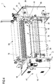
figure 4 is another simplified assonometric view, from the back (or of exit of the flexible laminar surfaces already finished), of the finishing machine of the invention; -
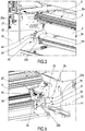
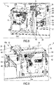
figure 5 is an assonometric view of a first constructive assembly of the machine offigure 4 , with the lower cylinder arranged in the main working position; -
figure 6 is the view offigure 5 with the lower cylinder arranged in the auxiliary release position; -
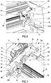
figure 7 is an assonometric view of a second constructive assembly of the machine offigure 4 ; -
figure 8 is a further assonometric view, from one side, of the finishing machine of the invention; -
figure 9 is another assonometric view, from the side opposite to that one of the view offigure 8 , of the finishing machine of the invention; -
figures 10 and 11 are two distinct assonometric views of the finishing machine of the invention, with the lower cylinder extracted and removed from the load-bearing frame; -
figures 12-21 are different assonometric, also simplified and partial, views of the finishing machine of the invention highlighting the operative sequence with which the lower cylinder passes from the main working position to the auxiliary release position and from the latter to the extracted position which allows maintenance, washing, repair and/or replacement thereof. - The machine for finishing flexible laminate surfaces P, such as the tanning industry leathers, used for the external coating of objects such as, for instance, furniture, shoes, bags, belts, jackets, seats or other parts of car bodywork, is illustrated in
figure 1 where it is globally numbered with 1. - The leathers P that can be worked with the
finishing machine 1 of the invention include not only the smaller ones (so-called "mezzine" and having a width of 1,800÷2,400 mm) but also those ones that reach a higher width, up to 3,400 mm. As it can be seen, thefinishing machine 1 comprises: - a load-bearing frame, generally indicated 2 and suitable to rest on a reference surface S, such as the flooring of an industrial plant;
- a lower transport and
contrast cylinder 3, covered with flexible material and firmly coupled to the load-bearingframe 2, operatively connected with first motorization means, visible tofigures 7 and9 where they are numbered as a whole with 4, suitable to rotate it around a first transverse axis X1 defined by thelower cylinder 3; - an
upper coating cylinder 5, provided with an engravedouter surface 5a and stably coupled to the load-bearingframe 2, operatively connected with second motorization means, visible infigure 8 where they're marked as a whole with 6, suitable to rotate it around a second transverse axis X2 defined by theupper cylinder 5 which is superiorly facing and opposed to thelower cylinder 3 from which it is spaced apart to define between thelower cylinder 3 and theupper cylinder 5 a narrow andlaminar passage light 7 suitable to receive one at a time spread flexible laminar surfaces P at least partly supported by thelower cylinder 3; - a
transversal blade 8, coupled to the load-bearingframe 2 and operatively connected with theupper cylinder 5 on whoseouter surface 5a distributes a film of liquid product L which theupper cylinder 5, while rotating around the second transverse axis X2, deposits by its pressure, at thelaminar passage light 7, on the upper face Ps of the flexible laminar surfaces P advancing along a prefixed direction F supported by the lower transport andcontrast cylinder 3. - According to the invention, the ratio D1/D2 between the diameter D1 of the
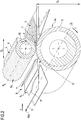
lower cylinder 3 and the diameter D2 of the upper cylinder 5 (diameters shown infigure 2 ) presents a value comprised between 1.35 and 1.40 (1.35 ≤ D1/D2 ≤ 1.40). - More particularly, such a ratio D1/D2 between the diameter D1 of the
lower cylinder 3 and the diameter D2 of theupper cylinder 5 presents a value between 1.36 and 1.39 (1.36 ≤ D1/D2 ≤ 1.39). - In a preferred but not binding manner, the ratio D1/D2 between the diameter D1 of the
lower cylinder 3 and the diameter D2 of theupper cylinder 5 has a value equal to 1.37. - Preferably but not necessarily, the
upper cylinder 5 has a diameter D2 comprised between 170 mm and 175 mm, generally equal to 173 mm. - As shown in
figure 2 , thelower cylinder 3 is rotated around the first transverse axis X1 in a direction T, for example clockwise, equal to the direction W in which theupper cylinder 5 is placed in rotation around the second transverse axis X2 in such a way that consecutive portions of theouter surface 3a and of theouter surface 5a respectively of thelower cylinder 3 and of theupper cylinder 5 interfere according to opposite rotation directions (and from below and from above, respectively) with the flexible laminar surface P as the latter passes to the inside of thelaminar passage light 7. - In a preferred but not exclusive and non-limiting manner, the
finishing machine 1 also comprises conveying and distensions means, as a whole indicated by 9, coupled to the load-bearingframe 2 and arranged upstream thelower cylinder 3 and theupper cylinder 5 and comprising first of all amain feed belt 10 suitable for receiving one at a time the spread flexible laminar surfaces P to be subjected to a finishing treatment and to advanced them along the prefixed direction F. - In addition, still more preferably, the conveying and distension means 9 include an
auxiliary feed belt 11 superiorly and at least partly facing and opposite to themain feed belt 10 from which it is spaced apart to define apassage gap 12 of the flexible laminar surfaces P spread and resting on theouter surface 10a of the main feed belt 10: taken together, themain feed belt 10 and theauxiliary feed belt 11 form an assembly (which can also be sold separately) which in the tanning and/or textile sector is usually identified as "spreader". - It should be noted that the rotation speed of the
lower cylinder 3 is higher than the speed with which the flexible laminar surfaces P advance along the prefixed direction F while they are supported by themain feed belt 10. - Furthermore, it should be noted that the first transverse axis X1 and the second transverse axis X2 are parallel each other, generally horizontal.
- In the described embodiment, the
lower cylinder 3 is operatively connected with the first motorization means 4 through a connectingjoint 13, clearly visible infigure 7 , that could be replaced by other mechanical transmission systems, such as for instance a joint cardan, in other embodiments of the invention finishing machine. - According to the preferred embodiment described herein of the invention, the
lower cylinder 3 is removably coupled to the load-bearingframe 2 through fixing means, on the whole indicated by 14, accessible by the operator who operates on them in such a way as to define for the lower cylinder 3: - a main working position, taken during the normal operating conditions of the machine 1 (including those of simple machine stop, due to production requirements) and for most of the time in which it can be used/is used in a production plant, in which the
lower cylinder 3 is stably coupled to the load-bearingframe 2 and facing theupper cylinder 5 from which it remains spaced apart by theaforementioned passage light 7; - an auxiliary release position, taken during temporary, special and extraordinary non-operating conditions of the
machine 1, for example to carry out its maintenance, in which thelower cylinder 3 is disengaged and separated from the load-bearingframe 2 to allow its extraction from the overall dimensions of the load-bearingframe 2. - More in detail, advantageously, the
fixing means 14 are partly contained in a first box-likeprotective body 15 belonging to the load-bearingframe 2 and made for example of aluminum, whose inner volume is accessible and can be inspected by the operator by acting on aaccess door 16 rotatably coupled to such a first box-likeprotective body 15. - The first box-like
protective body 15 contains the first motorization means 4 and is arranged laterally to thelower cylinder 3 andupper cylinder 4, outside the working area of the flexible laminar surfaces P between thelower cylinder 3 and the upper cylinder 5: in essence, the width of the working area coincides precisely with the length of the twocylinders opening 17 made in aninner wall 15a of the first box-likeprotective body 15 and projects from opposite parts of saidinner wall 15a. Moreover, the fixing means 14 are, preferably, partly arranged close to theinner wall 15a of the first box-likeprotective body 15 and near the twoends lower cylinder 3, facing the working area of flexible laminar surfaces P. - The constructive measures just described allow to mechanically isolate at least (but not only, as it will be clear below) the first motorization means 4 and part of the fixing means 14 from the working area of the flexible laminar surfaces P, preserving them to a greater extent than the known art from the contact with impurities, powders or other foreign bodies that are generated during the finishing treatment and that can even seriously affect the functioning thereof.
- Preferably, but not exclusive, the fixing means 14 comprise:
- a
shaped bracket 18, provided with a first end connected with the first motorization means 4 and a second end detachably connected with a first shapedplate 19 firmly coupled to afirst end 3b of thelower cylinder 3 in such a way as to interpose itself between the first motorization means 4 and aside edge 3d of thelower cylinder 3 itself; - a first safety group, overall indicated with 20, arranged at a
rear portion 19a of the first shapedplate 19 and at theinner wall 15a of the first box-likeprotective body 15; - a second security group, as a whole numbered with 21, arranged at:
- a
rear portion 22a of a second shapedplate 22, firmly coupled to asecond end 3c of thelower cylinder 3 and opposite and facing the first shapedplate 19; - an
inner wall 23a of a second box-likeprotective body 23, containing the second motorization means 6 (which set the engravedupper cylinder 5 in rotation) and opposite and facing the first box-shapedbody 15.
- a
- In particular, the
first plate 19 and thesecond plate 22 have a profile that is equal each other which mainly extends along a plane orthogonal to the transverse axis X1 of thelower cylinder 3. - Both the
first plate 19 and thesecond plate 22 end, at afront portion rear portion front handle 24 accessible by the operator who manoeuvres it during thelower cylinder 3 extraction phase from the load-bearing frame 2 and the subsequent re-introduction phase, to put it back in the main working position. - As far as the second box-like
protective body 23 is concerned, it is arranged as well laterally to thelower cylinder 3 and the upper cylinder 4 (on the opposite side compared to the first box-like body 15), outside the working area of the flexible laminar surfaces P between the aforesaid twocylinders protective body 23 contains other components traditionally provided for this type of machine, such as for example thepneumatic piston 25 for cylinders changing in themagazine 54 defined in the upper part of the load-bearing frame 2. Like the first box-like body 15, the second box-like body 23 also contains the actuation means, generally numbered with 47, suitable to adjust the distance of thelower cylinder 3 from the upper cylinder 5 (and, in turn, the height of thepassage light 7 and, therefore, the working thickness of the flexible laminar surfaces P), as it will be shortly better highlighted. - In order to ease extraction of the
lower cylinder 3 from the load-bearing frame 2 (and obviously its subsequent re-introduction into the latter), the lower cylinder includes twogrooved wheels 26, 27 (visible for instance infigures 1 and4 ), arranged one at thefirst end 3b and the other one at thesecond end 3c of thelower cylinder 3 to be interposed, respectively, between thefirst plate 19 and the first box-like body 15 and between thesecond plate 22 and the second box-like body 23. - In a preferred but not binding manner, the
first safety group 20 and thesecond safety group 21 include, as shown inFigures 5-7 : - a
shaped block clamp 28 fixed to theinner wall protective body 15 and second box-likeprotective body 23, respectively; - one or more
auxiliary rollers 29 coupled to thefirst plate 19 and to thesecond plate 22 at therear portion lower cylinder 3 takes the main working position - in aninners seat 30, visible infigure 6 and communicating with the outside inferiorly and laterally, defined in the shapedblock clamp 28. - Advantageously, the finishing
machine 1 of the invention also comprises guide means, indicated as a whole with 31, coupled to the load-bearing frame 2 and cooperating with thegrooved wheels lower cylinder 3 from the overall dimensions of the load-bearing frame 2 starting from its auxiliary release position as previously defined. - Preferably but not exclusively, the guide means 31 comprise:
- first guide means, as a whole indicated by 32, firmly and definitively (in the sense that they are never removed after their installation/application) coupled to the
inner wall like body 15 and of the second box-like body 23 and slidingly supporting thegrooved wheels auxiliary rollers 29 when thelower cylinder 3 takes the aforesaid auxiliary release position; - second guiding means, generally indicated with 33 and visible in
figures 10 and 11 , stably but removably coupled to the first guiding means 32 and slidably supporting thegrooved wheels auxiliary rollers 29 during the extraction of saidlower cylinder 3 from the load-bearing frame 2 and in their turn supported by an auxiliary structure, as a whole indicated with 34, suitable to be arranged upstream thelower cylinder 3 andupper cylinder 5 and to rest on the reference surface S. - More specifically, the second guide means 33 are installed in the finishing
machine 1 of the invention only when, occasionally (when necessary, but generally once every one or two years) the rubberizedlower cylinder 3 takes the auxiliary release position and it must be removed from the load-bearing frame 2 for proper general maintenance or replacement. - The
auxiliary structure 34 comprises twovertical uprights crosspiece 37, which support a pair of respectiveauxiliary tracks main track inner wall like body 15 and second box-like body 23. - At preferred but non limitative example, the fixing means 14 are operatively connected with adjustment means, on the whole indicated by 42, useful for varying the position of the
lower cylinder 3 to vary the distance between thelower cylinder 3 and theupper cylinder 5 changes and, consequently, the height of thepassage light 7, as the thickness of the flexible laminar surfaces P passing through it and/or of the quantity of film of liquid product L to be applied on the upper face Ps of the flexible laminar surfaces P to be perform their finishing treatment varies. - In particular and purely preferred manner, the adjustment means 42 comprise:
- two
side bars front portion 19b of the first shapedplate 19 and the other one to thefront portion 22b of thesecond plate 22, projecting laterally from thefirst plate 19 and from thesecond plate 22, respectively, and inserted into two throughslots protective body 15 and the other one in the second box-likeprotective body 23, in such a way that the side bars 43, 44 are partly contained into the respective first box-like body 15 and second box-like body 23 and partly protruding outwardly from theinner wall protective bodies - actuation means, indicated as a whole with 47, contained in the first box-
like body 15 and in the second box-like body 23 where they are operatively connected with a first end 43a, 44a of each of these side bars 43, 44. - Specifically, the actuation means 47 make sliding the side bars 43, 44 inside the respective through
slots lower cylinder 3 with respect to theupper cylinder 5. - The actuation means 47 comprise, in a purely preferential and non-binding way, a pair of pneumatic pistons (not shown for the sake of simplicity), one contained into the first box-
like body 15 and the other one in the second box-like body 23. -
Figures 15 and19 also show that, preferably but appropriately, the side bars 43, 44 are connected each other by a spacer reinforcing element 50 (typically a rigid rod, for example having a circular or prismatic profile) suitable to stabilize their operability, having substantially the same length of thelower cylinder 3 and contained in the overall dimensions of theloadbearing frame 2, particularly between the two box-like bodies - The finishing
machine 1 of the present invention also comprises a transfer belt, not shown for the sake of simplicity in the attached drawings, arranged functionally downstream theprocessing cylinders - The operation of the finishing
machine 1 of the present invention is managed by a central processing and control unit controlled by the operator through acontrol panel 58, visible for example infigure 10 . -
Figures 12 to 21 show the operating sequence to be adopted for extracting thelower cylinder 3, and thecarriage system 51 which makes it sliding, from the load-bearing frame 2, starting from the operating situation shown infigure 12 , in which the finishingmachine 1 of the invention is in use conditions and thelower cylinder 3 is in its traditional main working position. - In
figure 13 , the finishingmachine 1 is firstly turned off and the spreader (the previously defined conveying and distension assembly 9) is moved back by the operator according to the direction given by the arrow G. - Subsequently, the operator proceeds to remove the
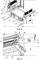
side trays figure 14 ) and of the transverse cleaning blade 53 (also called the "wiper blade", seefigure 15 ) operatively connected with thelower cylinder 3 to clean and/or dry theouter surface 3a thereof. - The operator then couples the removable
auxiliary structure 34 to the load-bearing frame 2, in the front part of this (in this way, in practice, the spreader is temporarily replaced by the auxiliary structure 34), as shown infigure 16 and he removes theblock clamp 54 of thefirst safety group 20 andsecond safety group 21, thus releasing theauxiliary rollers 29 from theinner seat 30 of the shapedblock clamp 28. - In this phase, moreover, the operator releases the universal joint 55 from the leather-detaching roller group 56 (see
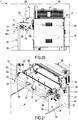
figure 17 ) and remove thegearmotor 57 and the connecting joint 13 from thelower cylinder 3, thus releasing the latter from the first motorization means 4 (seefigure 18 ). - Finally, the operator removes the side bars 43, 44 from the respective shaped
plates 19, 22 (keeping them in any case constrained to the respective pneumatic pistons) and possibly also the spacer reinforcing element 50 (seefigure 19 ) and, following the direction given by the arrow K infigure 20 , extracts from the inlet (or from thefront part 52 of the machine 1) thelower cylinder 3 and thecarriage system 51 which supports it, causing it to slide outwardly along firstly themain tracks auxiliary tracks auxiliary structure 34. - In this position, the operator removes the screws (not shown) of the supports (not shown) of the rubberized lower cylinder (or roller) 3 and lifts the latter upwardly (according to the arrows indicated with R) to allocate it to a maintenance station, outside the finishing
machine 1 of the invention. - It is therefore evident that, by means of the finishing
machine 1 of the present invention, the particular advantage of removing more quickly and more easily than the known art thelower cylinder 3 from the load-bearing frame 2 to carry out its complete and accurate, dedicated and separate maintenance, with simpler manoeuvres performed also by a single operator, is achieved. - In this aspect linked to maintenance of the lower cylinder, the finishing machine of the invention is more versatile compared to equivalent finishing machines of prior art: not by chance, the lower cylinder, with its drag carriage, is removable from the load-bearing frame from the front part (that one where the entry of flexible laminar surfaces occurs) after removing any but usually present conveying and distension means (spreader), and this in a way faster and easier than in the known art.
- By virtue of the description just given, it is therefore understood that the improved machine for finishing flexible laminar surfaces used as coating of objects, items or products of the present invention achieves the purposes and reaches the advantages mentioned above.
- Upon execution, changes could be made to the improved machine for the finishing of flexible laminar surfaces used as coating of objects, items or products of the invention, consisting, for example, in a number of transversal blades different from that one previously indicated and visible in the attached figures, which express only the preferred embodiment of the invention: indeed, alternative and optional embodiments of the finishing machine of the invention could provide a number of transversal blades greater than one, in which case the machine of the invention could include a plurality of transversal blades arranged side-by-side and aligned each other along a linear axis parallel to the first transverse axis and the second transverse axis.
- The finishing machine of the invention, in its basic and essential components expressed in the attached
claim 1, can also be produced and marketed in kit form with the conveying and distension means, removably coupled to its load-bearing frame, with the auxiliary structure arranged in front of the lower and upper processing cylinders (rollers) and supporting the second guide means, also removably coupled to the load-bearing frame and/or to the grad belt (in case it is removably coupled to the load-bearing frame). - It is, finally, clear that several other changes could be made to the improved finishing machine concerned, without departing from the principle of novelty intrinsic in the inventive idea expressed herein, as it is clear that, in the practical implementation of the invention, materials, shapes and sizes of the illustrated details could be changed, as needed, and replaced with others technically equivalent.
- Where the constructive features and techniques mentioned in the following claims are followed by reference numbers or signs, those reference signs have been introduced with the sole objective of increasing the intelligibility of the claims themselves and therefore they have no limiting effect on the interpretation of each element identified, by way of example only, by these reference signs.
Claims (20)
- Machine (1) for finishing flexible laminar surfaces (P) used as coating of objects comprising:- a load-bearing frame (2) suitable to rest on a reference surface (S);- a lower transport and contrast cylinder (3), covered with flexible material and stably coupled to said load-bearing frame (2), operatively connected with first motorization means (4) suitable to rotate it around a first transverse axis (X1) defined by said lower cylinder (3);- an upper coating cylinder (5), provided with an outer surface (5a) engraved and stably coupled to said load-bearing frame (2), operatively connected with second motorization means (6) suitable to rotate it around a second transverse axis (X2) defined by said upper cylinder (5) which is superiorly facing and opposed to said lower cylinder (3) from which it is spaced apart to define a passage light (7) between said lower cylinder (3) and said upper cylinder (5) suitable to receive one at a time spread flexible laminar surfaces (P) at least partly supported by said lower cylinder (3);- at least one transversal blade (8), coupled to said load-bearing frame (2), operatively connected with said upper cylinder (5) on said outer surface (5a) of which it is suitable to distribute a film of liquid product (L) which said upper cylinder (5), while rotating around said second transverse axis (X2), deposits by pressure, at said passage light (7), on the upper face (Ps) of said flexible laminar surfaces (P) advancing along a prefixed direction (F) and supported by said lower transport and contrast cylinder (3),characterized in that the ratio (D1/D2) between the diameter (D1) of said lower cylinder (3) and the diameter (D2) of said upper cylinder (5) has a value comprised between 1.35 and 1.40 (1.35 ≤ D1/D2 ≤ 1.40).
- Machine (1) according to claim 1), characterized in that said ratio (D1/D2) between said diameter (D1) of said lower cylinder (3) and said diameter (D2) of said upper cylinder (5) has a value between 1.36 and 1.39 (1.36 ≤ D1/D2 ≤ 1.39).
- Machine according to claim 1) or 2), characterized in that said ratio (D1/D2) between said diameter (D1) of said lower cylinder (3) and said diameter (D2) of said upper cylinder (5) has a value equal to 1.37.
- Machine (1) according to any of the previous claims, characterized in that said lower cylinder (3) is rotated around said first transverse axis (X1) in a direction (T) equal to that one (W) in which said upper cylinder (5) is placed in rotation around said second transverse axis (X2).
- Machine (1) according to any of the previous claims, characterized in that it comprises conveying and distension means (9), coupled to said load-bearing frame (2) and arranged upstream said lower cylinder (3) and said upper cylinder (5) and comprising at least one main feed belt (10) suitable to receive one at a time said spread flexible laminar surfaces (P) to be subjected to a finishing treatment and to advance them along said prefixed direction (F).
- Machine (1) according to claim 5), characterized in that said conveying and distension means (9) include an auxiliary feed belt (11) superiorly and at least partly facing and opposite to said main feed belt (10) from which it is spaced apart to define a passage gap (12) of said flexible laminar surfaces (P) resting on an outer surface (10a) of said main feed belt (10).
- Machine (1) according to any of the previous claims, characterized in that said lower cylinder (3) is operatively connected with said first motorization means (4) through a connecting joint (13).
- Machine (1) according to any of the previous claims, characterized in that said lower cylinder (3) is detachably coupled to said load-bearing frame (2) through fixing means (14) accessible by the operator who operates on them in such a way as to define for said lower cylinder (3) a main working position, taken during the normal operating conditions of said machine (1), in which said lower cylinder (3) is firmly coupled to said load-bearing frame (2) and facing to said upper cylinder (5) from which it remains spaced apart by said passage light (7), and an auxiliary release position, taken during the temporary non-operating conditions of said machine (1), in which said lower cylinder (3) is disengaged and separated from said load-bearing frame (2) to allow its extraction from the overall dimensions of said load-bearing frame (2).
- Machine (1) according to claim 8), characterized in that said fixing means (14) are partly contained in a first box-like protective body (15) belonging to said load-bearing frame (2), containing said first motorization means (4) and arranged laterally to said lower cylinder (3) and said upper cylinder (4), outside the working area of said flexible laminar surfaces (P) between said lower cylinder (3) and said upper cylinder (5).
- Machine (1) according to claim 9), characterized in that said fixing means (14) are partly arranged close an inner wall (15a) of said first box-like protective body (15) and near two ends (3b, 3c) opposite each other of said lower cylinder (3), facing said working area of said flexible laminar surfaces (P).
- Machine (1) according to claim 8), 9) or 10), characterized in that said fixing means (14) comprise:- a shaped bracket (18), provided with a first end connected with said first motorization means (4) and with a second end detachably connected with a first shaped plate (19) stably coupled to a first end (3b) of said lower cylinder (3) in such a way as to interpose itself between said first motorization means (4) and a side edge (3d) of said lower cylinder (3);- a first safety group (20) arranged at a rear portion (19a) of said first shaped plate (19) and at an inner wall (15a) of said first box-like protective body (15);- a second safety group (21) arranged at:• a rear portion (22a) of a second shaped plate (22), firmly coupled to a second end (3c) of said lower cylinder (3) and opposite and facing said first shaped plate (19);• an inner wall (23a) of a second box-like protective body (23), containing said second motorization means (6) and opposite and facing said first box-like body (15).
- Machine (1) according to claim 11), characterized in that said first plate (19) and said second plate (22) have a profile equal each other and end each at a front portion (19b, 22b) opposite to said rear portion (19a, 22a), with a front handle (24) accessible by the operator.
- Machine (1) according to claim 11), characterized in that said second box-like protective body (23) is arranged laterally to said lower cylinder (3) and said upper cylinder (4), outside the working area of said flexible laminar surfaces (P) between said lower cylinder (3) and said upper cylinder (5).
- Machine (1) according to claim 11), characterized in that said lower cylinder (3) comprises two grooved wheels (26, 27), arranged one at said first end (3b) and the other one at said second end (3c) of said lower cylinder (3) to be interposed, respectively, between said first plate (19) and said first box-like protective body (15) and between said second plate (22) and said second box-like protective body (23).
- Machine (1) according to claim 11), characterized in that said first safety group (20) and said second safety group (21) include:- a shaped block clamp (28) fixed to said inner wall (15a, 23a) both of said first box-shaped protective body (15) and of said second box-like protective body (23);- one or more auxiliary rollers (29) coupled to said first plate (19) and with said second plate (20) at said rear portion (19a, 22a), firmly housed, when said lower cylinder (3) takes said main working position, in an inner seat (30) communicating with the outside inferiorly and laterally, defined in said shaped block clamp (28).
- Machine (1) according to claim 13), characterized in that it comprises guide means (31), coupled to said load-bearing frame (2) and cooperating with said grooved wheels (26, 27), suitable to ease controlled and secure extraction of said lower cylinder (3) from said overall dimensions of said load-bearing frame (2).
- Machine (1) according to claim 16) when dependent on claim 15), characterized in that said guide means (31) include:- first guide means (32), firmly and definitively coupled to said inner wall (15a, 23a) of said first box-like body (15) and said second box-like body (23) and slidingly supporting said grooved wheels (26, 27) and said auxiliary rollers (29) when said lower cylinder (3) takes said auxiliary release position;- second guide means (33), stably but removably coupled to said first guide means (32) and slidingly supporting said grooved wheels (26, 27) and said auxiliary rollers (29) during said extraction of said lower cylinder (3) from said load-bearing frame (2) and supported by an auxiliary structure (34) suitable to be arranged upstream said lower cylinder (3) and said upper cylinder (5) and to rest on said reference surface (S).
- Machine (1) according to any of the claims 8) to 17), characterized in that said fixing means (14) are operatively connected with adjustment means (42) of the position of said lower cylinder (3), to vary the distance between said lower cylinder (3) and said upper cylinder (5) and, consequently, the height of said passage light (7), as the thickness of said flexible laminar surfaces (P) in transit through of it and/or of the quantity of said film of liquid product (L) to be applied on said upper face (Ps) of said flexible laminar surfaces (P) change.
- Machine according to claim 18) when dependent on claim 11), characterized in that said adjustment means (42) comprise:- two side bars (43, 44), removably fixed one to said front portion (19b) of said first shaped plate (19) and the other one to said front portion (22b) of said second plate (22), projecting laterally from said first (19) and second plate (22) and inserted into two through slots (45, 46) with an elongated and arched profile made one in said first box-like body (14) and the other one in said second box-like body (23), in such a way as to be partly contained into said first (15) and second box-like protective body (23) and partly protruding outwardly from an inner wall (15a, 23a) of said first (15) and second box-like protective body (23);- actuation means (47), contained into said first (15) and second protective box-like body (23) where they are operatively connected with a first end (43a, 44a) of each of said side bars (43, 44),said side bars (43, 44) being made sliding inside said through slots (45, 46) according to a curved trajectory in order to adjust said position of said lower cylinder (3) with respect to said upper cylinder (5).
- Machine (1) according to claim 19) when claim 11) depends on claim 8), characterized in that said side bars (43, 44) are connected each other through a spacer reinforcing element (50) suitable to stabilize their operability, having substantially the same length as said lower cylinder (3) and contained in said overall dimensions of said load-bearing frame (2).
Applications Claiming Priority (1)
| Application Number | Priority Date | Filing Date | Title |
|---|---|---|---|
| IT102018000007456A IT201800007456A1 (en) | 2018-07-24 | 2018-07-24 | MACHINE FOR THE FINISHING OF FLEXIBLE LAMINARY SURFACES FOR COVERING OBJECTS |
Publications (3)
| Publication Number | Publication Date |
|---|---|
| EP3599289A2 true EP3599289A2 (en) | 2020-01-29 |
| EP3599289A3 EP3599289A3 (en) | 2020-03-04 |
| EP3599289B1 EP3599289B1 (en) | 2021-11-03 |
Family
ID=63965782
Family Applications (1)
| Application Number | Title | Priority Date | Filing Date |
|---|---|---|---|
| EP19188041.8A Active EP3599289B1 (en) | 2018-07-24 | 2019-07-24 | Machine for finishing flexible laminar surfaces used as coating of objects |
Country Status (3)
| Country | Link |
|---|---|
| EP (1) | EP3599289B1 (en) |
| ES (1) | ES2905723T3 (en) |
| IT (1) | IT201800007456A1 (en) |
Cited By (4)
| Publication number | Priority date | Publication date | Assignee | Title |
|---|---|---|---|---|
| CN112495688A (en) * | 2020-11-26 | 2021-03-16 | 上海明克包装制品有限公司 | Sealing paper glue brushing machine for packaging bag |
| IT202000003311A1 (en) * | 2020-02-18 | 2021-08-18 | Ge Ma Ta Spa | Leather finishing machine |
| IT202200008819A1 (en) * | 2022-05-02 | 2023-11-02 | Ing Polin & C S P A | “MACHINE FOR FORMING A FOOD PRODUCT, PREFERABLY A BISCUITS” |
| CN117225638A (en) * | 2023-11-13 | 2023-12-15 | 兴化市新光合金材料有限公司 | Stainless steel wire surface oiling equipment |
Citations (3)
| Publication number | Priority date | Publication date | Assignee | Title |
|---|---|---|---|---|
| EP0484740A1 (en) | 1990-11-09 | 1992-05-13 | Officine Di Cartigliano S.P.A. | Roller dyeing machine for surface impregnating hides and similar products |
| EP1441037A1 (en) | 2003-01-24 | 2004-07-28 | Industrie Meccaniche Bergi-OFB S.p.A. | Spreader machine for tannery hides |
| EP2177632A1 (en) | 2008-10-09 | 2010-04-21 | GE.MA.TA. S.p.A. | Machine for roller finishing skin, fake skin, fabrics, synthetic material and the like |
Family Cites Families (3)
| Publication number | Priority date | Publication date | Assignee | Title |
|---|---|---|---|---|
| IT1390925B1 (en) * | 2008-08-05 | 2011-10-19 | Ge Ma Ta Spa | ROLLER FINISHING MACHINE FOR NATURAL, LEATHER AND THE LIKE, WORKING WITH THE "SINCRO" COSIDDETTO METHOD. |
| EP3103887B1 (en) * | 2015-06-11 | 2019-03-27 | GE.MA.TA. S.p.A. | Machine for continuous dyeing of leather goods |
| EP3150728A1 (en) * | 2015-10-02 | 2017-04-05 | GE.MA.TA. S.p.A. | Machine for roller finishing natural hides and leather |
-
2018
- 2018-07-24 IT IT102018000007456A patent/IT201800007456A1/en unknown
-
2019
- 2019-07-24 EP EP19188041.8A patent/EP3599289B1/en active Active
- 2019-07-24 ES ES19188041T patent/ES2905723T3/en active Active
Patent Citations (3)
| Publication number | Priority date | Publication date | Assignee | Title |
|---|---|---|---|---|
| EP0484740A1 (en) | 1990-11-09 | 1992-05-13 | Officine Di Cartigliano S.P.A. | Roller dyeing machine for surface impregnating hides and similar products |
| EP1441037A1 (en) | 2003-01-24 | 2004-07-28 | Industrie Meccaniche Bergi-OFB S.p.A. | Spreader machine for tannery hides |
| EP2177632A1 (en) | 2008-10-09 | 2010-04-21 | GE.MA.TA. S.p.A. | Machine for roller finishing skin, fake skin, fabrics, synthetic material and the like |
Cited By (9)
| Publication number | Priority date | Publication date | Assignee | Title |
|---|---|---|---|---|
| IT202000003311A1 (en) * | 2020-02-18 | 2021-08-18 | Ge Ma Ta Spa | Leather finishing machine |
| EP3868898A1 (en) | 2020-02-18 | 2021-08-25 | GE.MA.TA. SpA | Machine for finishing hides |
| EP3868898B1 (en) | 2020-02-18 | 2022-06-01 | GE.MA.TA. SpA | Machine for finishing hides |
| CN112495688A (en) * | 2020-11-26 | 2021-03-16 | 上海明克包装制品有限公司 | Sealing paper glue brushing machine for packaging bag |
| CN112495688B (en) * | 2020-11-26 | 2022-06-14 | 上海明克包装制品有限公司 | Sealing paper glue brushing machine for packaging bag |
| IT202200008819A1 (en) * | 2022-05-02 | 2023-11-02 | Ing Polin & C S P A | “MACHINE FOR FORMING A FOOD PRODUCT, PREFERABLY A BISCUITS” |
| EP4272559A1 (en) * | 2022-05-02 | 2023-11-08 | ING. POLIN & C. S.p.A. | A machine for forming a food product, preferably a biscuit |
| CN117225638A (en) * | 2023-11-13 | 2023-12-15 | 兴化市新光合金材料有限公司 | Stainless steel wire surface oiling equipment |
| CN117225638B (en) * | 2023-11-13 | 2024-02-23 | 兴化市新光合金材料有限公司 | Stainless steel wire surface oiling equipment |
Also Published As
| Publication number | Publication date |
|---|---|
| EP3599289B1 (en) | 2021-11-03 |
| ES2905723T3 (en) | 2022-04-11 |
| EP3599289A3 (en) | 2020-03-04 |
| IT201800007456A1 (en) | 2020-01-24 |
Similar Documents
| Publication | Publication Date | Title |
|---|---|---|
| EP3599289B1 (en) | Machine for finishing flexible laminar surfaces used as coating of objects | |
| US3393538A (en) | Tanning and tawing (or leather dressing) machine for splitting hides and skins | |
| EP1743739B1 (en) | Device for blasting rotationally symmetrical parts, in particular metal parts | |
| DE1184727B (en) | Device and method for the continuous mechanical upsetting of textile webs | |
| US3030917A (en) | Coating of webs and the like | |
| CS338391A3 (en) | Roller dyeing machine for surface impregnation of leathers and the like articles | |
| ITVI20080235A1 (en) | LEATHER ROLLER FINISHING MACHINE, FINAL LEATHER, FABRIC, SYNTHETIC AND SIMILAR MATERIAL. | |
| US1998770A (en) | Method of and apparatus for grinding and polishing flexible sheets | |
| EP2944384B1 (en) | Apparatus for cleaning the transparent endless belt for rapid uv polymerization of the paint that coats products with a mainly flat surface | |
| US2934863A (en) | Sanding machine | |
| US3911703A (en) | Machine for processing skins or hides | |
| DE4038031C2 (en) | ||
| US1799002A (en) | Knife-coating machine | |
| US2540367A (en) | Method of grinding and finishing strip metal | |
| US1937164A (en) | Machine for coating paper and fabric | |
| US1828793A (en) | Apparatus for feeding and cutting material | |
| US2013196A (en) | Polishing machine | |
| DE3639264A1 (en) | Apparatus for the copy-grinding of cylindrical and spherical surfaces | |
| ITBO20120061A1 (en) | APPARATUS FOR CONFIRMING THE RAW SIDES OF WOODEN OR SIMILAR PANELS, A REGULAR APPEARANCE, SMOOTH AND ABLE TO RECEIVE ANY FINISHING TREATMENT. | |
| CN219723462U (en) | Coating device of coating | |
| DE2250735A1 (en) | GRINDING MACHINE FOR RE-PROCESSING OF CERAMIC PRODUCTS, IN PARTICULAR OF DISC AND BOWL FEET | |
| US2014470A (en) | Machine and method for use in stretching and softening leather | |
| US3855823A (en) | Apparatus for continuously chamoising halves | |
| US587717A (en) | Machine for treating hides | |
| DE7037343U (en) | DEVICE FOR THE FEEDING OF SKINS, FURS, LEATHER AND THE LIKE. ON MACHINING MACHINES |
Legal Events
| Date | Code | Title | Description |
|---|---|---|---|
| PUAI | Public reference made under article 153(3) epc to a published international application that has entered the european phase |
Free format text: ORIGINAL CODE: 0009012 |
|
| STAA | Information on the status of an ep patent application or granted ep patent |
Free format text: STATUS: THE APPLICATION HAS BEEN PUBLISHED |
|
| AK | Designated contracting states |
Kind code of ref document: A2 Designated state(s): AL AT BE BG CH CY CZ DE DK EE ES FI FR GB GR HR HU IE IS IT LI LT LU LV MC MK MT NL NO PL PT RO RS SE SI SK SM TR |
|
| AX | Request for extension of the european patent |
Extension state: BA ME |
|
| PUAL | Search report despatched |
Free format text: ORIGINAL CODE: 0009013 |
|
| AK | Designated contracting states |
Kind code of ref document: A3 Designated state(s): AL AT BE BG CH CY CZ DE DK EE ES FI FR GB GR HR HU IE IS IT LI LT LU LV MC MK MT NL NO PL PT RO RS SE SI SK SM TR |
|
| AX | Request for extension of the european patent |
Extension state: BA ME |
|
| RIC1 | Information provided on ipc code assigned before grant |
Ipc: B05C 1/10 20060101ALI20200129BHEP Ipc: C14B 1/56 20060101AFI20200129BHEP |
|
| STAA | Information on the status of an ep patent application or granted ep patent |
Free format text: STATUS: REQUEST FOR EXAMINATION WAS MADE |
|
| 17P | Request for examination filed |
Effective date: 20200828 |
|
| RBV | Designated contracting states (corrected) |
Designated state(s): AL AT BE BG CH CY CZ DE DK EE ES FI FR GB GR HR HU IE IS IT LI LT LU LV MC MK MT NL NO PL PT RO RS SE SI SK SM TR |
|
| GRAP | Despatch of communication of intention to grant a patent |
Free format text: ORIGINAL CODE: EPIDOSNIGR1 |
|
| STAA | Information on the status of an ep patent application or granted ep patent |
Free format text: STATUS: GRANT OF PATENT IS INTENDED |
|
| INTG | Intention to grant announced |
Effective date: 20210511 |
|
| GRAS | Grant fee paid |
Free format text: ORIGINAL CODE: EPIDOSNIGR3 |
|
| GRAA | (expected) grant |
Free format text: ORIGINAL CODE: 0009210 |
|
| STAA | Information on the status of an ep patent application or granted ep patent |
Free format text: STATUS: THE PATENT HAS BEEN GRANTED |
|
| AK | Designated contracting states |
Kind code of ref document: B1 Designated state(s): AL AT BE BG CH CY CZ DE DK EE ES FI FR GB GR HR HU IE IS IT LI LT LU LV MC MK MT NL NO PL PT RO RS SE SI SK SM TR |
|
| REG | Reference to a national code |
Ref country code: GB Ref legal event code: FG4D |
|
| REG | Reference to a national code |
Ref country code: AT Ref legal event code: REF Ref document number: 1444001 Country of ref document: AT Kind code of ref document: T Effective date: 20211115 Ref country code: CH Ref legal event code: EP |
|
| REG | Reference to a national code |
Ref country code: DE Ref legal event code: R096 Ref document number: 602019008874 Country of ref document: DE |
|
| REG | Reference to a national code |
Ref country code: IE Ref legal event code: FG4D |
|
| REG | Reference to a national code |
Ref country code: LT Ref legal event code: MG9D |
|
| REG | Reference to a national code |
Ref country code: NL Ref legal event code: MP Effective date: 20211103 |
|
| REG | Reference to a national code |
Ref country code: AT Ref legal event code: MK05 Ref document number: 1444001 Country of ref document: AT Kind code of ref document: T Effective date: 20211103 |
|
| REG | Reference to a national code |
Ref country code: ES Ref legal event code: FG2A Ref document number: 2905723 Country of ref document: ES Kind code of ref document: T3 Effective date: 20220411 |
|
| PG25 | Lapsed in a contracting state [announced via postgrant information from national office to epo] |
Ref country code: RS Free format text: LAPSE BECAUSE OF FAILURE TO SUBMIT A TRANSLATION OF THE DESCRIPTION OR TO PAY THE FEE WITHIN THE PRESCRIBED TIME-LIMIT Effective date: 20211103 Ref country code: LT Free format text: LAPSE BECAUSE OF FAILURE TO SUBMIT A TRANSLATION OF THE DESCRIPTION OR TO PAY THE FEE WITHIN THE PRESCRIBED TIME-LIMIT Effective date: 20211103 Ref country code: FI Free format text: LAPSE BECAUSE OF FAILURE TO SUBMIT A TRANSLATION OF THE DESCRIPTION OR TO PAY THE FEE WITHIN THE PRESCRIBED TIME-LIMIT Effective date: 20211103 Ref country code: BG Free format text: LAPSE BECAUSE OF FAILURE TO SUBMIT A TRANSLATION OF THE DESCRIPTION OR TO PAY THE FEE WITHIN THE PRESCRIBED TIME-LIMIT Effective date: 20220203 Ref country code: AT Free format text: LAPSE BECAUSE OF FAILURE TO SUBMIT A TRANSLATION OF THE DESCRIPTION OR TO PAY THE FEE WITHIN THE PRESCRIBED TIME-LIMIT Effective date: 20211103 |
|
| PG25 | Lapsed in a contracting state [announced via postgrant information from national office to epo] |
Ref country code: IS Free format text: LAPSE BECAUSE OF FAILURE TO SUBMIT A TRANSLATION OF THE DESCRIPTION OR TO PAY THE FEE WITHIN THE PRESCRIBED TIME-LIMIT Effective date: 20220303 Ref country code: SE Free format text: LAPSE BECAUSE OF FAILURE TO SUBMIT A TRANSLATION OF THE DESCRIPTION OR TO PAY THE FEE WITHIN THE PRESCRIBED TIME-LIMIT Effective date: 20211103 Ref country code: PT Free format text: LAPSE BECAUSE OF FAILURE TO SUBMIT A TRANSLATION OF THE DESCRIPTION OR TO PAY THE FEE WITHIN THE PRESCRIBED TIME-LIMIT Effective date: 20220303 Ref country code: PL Free format text: LAPSE BECAUSE OF FAILURE TO SUBMIT A TRANSLATION OF THE DESCRIPTION OR TO PAY THE FEE WITHIN THE PRESCRIBED TIME-LIMIT Effective date: 20211103 Ref country code: NO Free format text: LAPSE BECAUSE OF FAILURE TO SUBMIT A TRANSLATION OF THE DESCRIPTION OR TO PAY THE FEE WITHIN THE PRESCRIBED TIME-LIMIT Effective date: 20220203 Ref country code: NL Free format text: LAPSE BECAUSE OF FAILURE TO SUBMIT A TRANSLATION OF THE DESCRIPTION OR TO PAY THE FEE WITHIN THE PRESCRIBED TIME-LIMIT Effective date: 20211103 Ref country code: LV Free format text: LAPSE BECAUSE OF FAILURE TO SUBMIT A TRANSLATION OF THE DESCRIPTION OR TO PAY THE FEE WITHIN THE PRESCRIBED TIME-LIMIT Effective date: 20211103 Ref country code: HR Free format text: LAPSE BECAUSE OF FAILURE TO SUBMIT A TRANSLATION OF THE DESCRIPTION OR TO PAY THE FEE WITHIN THE PRESCRIBED TIME-LIMIT Effective date: 20211103 Ref country code: GR Free format text: LAPSE BECAUSE OF FAILURE TO SUBMIT A TRANSLATION OF THE DESCRIPTION OR TO PAY THE FEE WITHIN THE PRESCRIBED TIME-LIMIT Effective date: 20220204 |
|
| PG25 | Lapsed in a contracting state [announced via postgrant information from national office to epo] |
Ref country code: SM Free format text: LAPSE BECAUSE OF FAILURE TO SUBMIT A TRANSLATION OF THE DESCRIPTION OR TO PAY THE FEE WITHIN THE PRESCRIBED TIME-LIMIT Effective date: 20211103 Ref country code: SK Free format text: LAPSE BECAUSE OF FAILURE TO SUBMIT A TRANSLATION OF THE DESCRIPTION OR TO PAY THE FEE WITHIN THE PRESCRIBED TIME-LIMIT Effective date: 20211103 Ref country code: RO Free format text: LAPSE BECAUSE OF FAILURE TO SUBMIT A TRANSLATION OF THE DESCRIPTION OR TO PAY THE FEE WITHIN THE PRESCRIBED TIME-LIMIT Effective date: 20211103 Ref country code: EE Free format text: LAPSE BECAUSE OF FAILURE TO SUBMIT A TRANSLATION OF THE DESCRIPTION OR TO PAY THE FEE WITHIN THE PRESCRIBED TIME-LIMIT Effective date: 20211103 Ref country code: DK Free format text: LAPSE BECAUSE OF FAILURE TO SUBMIT A TRANSLATION OF THE DESCRIPTION OR TO PAY THE FEE WITHIN THE PRESCRIBED TIME-LIMIT Effective date: 20211103 Ref country code: CZ Free format text: LAPSE BECAUSE OF FAILURE TO SUBMIT A TRANSLATION OF THE DESCRIPTION OR TO PAY THE FEE WITHIN THE PRESCRIBED TIME-LIMIT Effective date: 20211103 |
|
| REG | Reference to a national code |
Ref country code: DE Ref legal event code: R097 Ref document number: 602019008874 Country of ref document: DE |
|
| PLBE | No opposition filed within time limit |
Free format text: ORIGINAL CODE: 0009261 |
|
| STAA | Information on the status of an ep patent application or granted ep patent |
Free format text: STATUS: NO OPPOSITION FILED WITHIN TIME LIMIT |
|
| 26N | No opposition filed |
Effective date: 20220804 |
|
| PG25 | Lapsed in a contracting state [announced via postgrant information from national office to epo] |
Ref country code: AL Free format text: LAPSE BECAUSE OF FAILURE TO SUBMIT A TRANSLATION OF THE DESCRIPTION OR TO PAY THE FEE WITHIN THE PRESCRIBED TIME-LIMIT Effective date: 20211103 |
|
| PG25 | Lapsed in a contracting state [announced via postgrant information from national office to epo] |
Ref country code: SI Free format text: LAPSE BECAUSE OF FAILURE TO SUBMIT A TRANSLATION OF THE DESCRIPTION OR TO PAY THE FEE WITHIN THE PRESCRIBED TIME-LIMIT Effective date: 20211103 |
|
| PG25 | Lapsed in a contracting state [announced via postgrant information from national office to epo] |
Ref country code: MC Free format text: LAPSE BECAUSE OF FAILURE TO SUBMIT A TRANSLATION OF THE DESCRIPTION OR TO PAY THE FEE WITHIN THE PRESCRIBED TIME-LIMIT Effective date: 20211103 |
|
| REG | Reference to a national code |
Ref country code: CH Ref legal event code: PL |
|
| REG | Reference to a national code |
Ref country code: BE Ref legal event code: MM Effective date: 20220731 |
|
| PG25 | Lapsed in a contracting state [announced via postgrant information from national office to epo] |
Ref country code: LU Free format text: LAPSE BECAUSE OF NON-PAYMENT OF DUE FEES Effective date: 20220724 Ref country code: LI Free format text: LAPSE BECAUSE OF NON-PAYMENT OF DUE FEES Effective date: 20220731 Ref country code: CH Free format text: LAPSE BECAUSE OF NON-PAYMENT OF DUE FEES Effective date: 20220731 |
|
| PG25 | Lapsed in a contracting state [announced via postgrant information from national office to epo] |
Ref country code: BE Free format text: LAPSE BECAUSE OF NON-PAYMENT OF DUE FEES Effective date: 20220731 |
|
| PG25 | Lapsed in a contracting state [announced via postgrant information from national office to epo] |
Ref country code: IE Free format text: LAPSE BECAUSE OF NON-PAYMENT OF DUE FEES Effective date: 20220724 |
|
| PGFP | Annual fee paid to national office [announced via postgrant information from national office to epo] |
Ref country code: FR Payment date: 20230608 Year of fee payment: 5 |
|
| PGFP | Annual fee paid to national office [announced via postgrant information from national office to epo] |
Ref country code: TR Payment date: 20230721 Year of fee payment: 5 Ref country code: IT Payment date: 20230623 Year of fee payment: 5 Ref country code: GB Payment date: 20230601 Year of fee payment: 5 Ref country code: ES Payment date: 20230808 Year of fee payment: 5 |
|
| PGFP | Annual fee paid to national office [announced via postgrant information from national office to epo] |
Ref country code: DE Payment date: 20230531 Year of fee payment: 5 |
|
| PG25 | Lapsed in a contracting state [announced via postgrant information from national office to epo] |
Ref country code: HU Free format text: LAPSE BECAUSE OF FAILURE TO SUBMIT A TRANSLATION OF THE DESCRIPTION OR TO PAY THE FEE WITHIN THE PRESCRIBED TIME-LIMIT; INVALID AB INITIO Effective date: 20190724 |
|
| PG25 | Lapsed in a contracting state [announced via postgrant information from national office to epo] |
Ref country code: MK Free format text: LAPSE BECAUSE OF FAILURE TO SUBMIT A TRANSLATION OF THE DESCRIPTION OR TO PAY THE FEE WITHIN THE PRESCRIBED TIME-LIMIT Effective date: 20211103 Ref country code: CY Free format text: LAPSE BECAUSE OF FAILURE TO SUBMIT A TRANSLATION OF THE DESCRIPTION OR TO PAY THE FEE WITHIN THE PRESCRIBED TIME-LIMIT Effective date: 20211103 |