EP3868704A1 - Hose for a removal system and method for removing liquid from a container by means of a removal system - Google Patents
Hose for a removal system and method for removing liquid from a container by means of a removal system Download PDFInfo
- Publication number
- EP3868704A1 EP3868704A1 EP20158022.2A EP20158022A EP3868704A1 EP 3868704 A1 EP3868704 A1 EP 3868704A1 EP 20158022 A EP20158022 A EP 20158022A EP 3868704 A1 EP3868704 A1 EP 3868704A1
- Authority
- EP
- European Patent Office
- Prior art keywords
- hose
- closure means
- head
- removal head
- container
- Prior art date
- Legal status (The legal status is an assumption and is not a legal conclusion. Google has not performed a legal analysis and makes no representation as to the accuracy of the status listed.)
- Pending
Links
- 239000007788 liquid Substances 0.000 title claims abstract description 33
- 238000000034 method Methods 0.000 title claims description 12
- 238000000605 extraction Methods 0.000 claims description 23
- 230000000903 blocking effect Effects 0.000 claims description 15
- 238000003825 pressing Methods 0.000 claims description 5
- 238000013461 design Methods 0.000 description 4
- 230000005540 biological transmission Effects 0.000 description 2
- 238000005070 sampling Methods 0.000 description 2
- 230000006978 adaptation Effects 0.000 description 1
- 238000013475 authorization Methods 0.000 description 1
- 230000015572 biosynthetic process Effects 0.000 description 1
- 231100000481 chemical toxicant Toxicity 0.000 description 1
- 230000000295 complement effect Effects 0.000 description 1
- 238000012790 confirmation Methods 0.000 description 1
- 238000010276 construction Methods 0.000 description 1
- 238000011109 contamination Methods 0.000 description 1
- 230000008878 coupling Effects 0.000 description 1
- 238000010168 coupling process Methods 0.000 description 1
- 238000005859 coupling reaction Methods 0.000 description 1
- 230000001419 dependent effect Effects 0.000 description 1
- 238000011161 development Methods 0.000 description 1
- 230000018109 developmental process Effects 0.000 description 1
- 238000005553 drilling Methods 0.000 description 1
- 238000009510 drug design Methods 0.000 description 1
- 210000003746 feather Anatomy 0.000 description 1
- 238000005755 formation reaction Methods 0.000 description 1
- 230000005484 gravity Effects 0.000 description 1
- 238000007654 immersion Methods 0.000 description 1
- 238000004519 manufacturing process Methods 0.000 description 1
- 239000000463 material Substances 0.000 description 1
- 230000000284 resting effect Effects 0.000 description 1
- 230000000717 retained effect Effects 0.000 description 1
- 238000007493 shaping process Methods 0.000 description 1
- 239000000126 substance Substances 0.000 description 1
- 239000003440 toxic substance Substances 0.000 description 1
- 238000012546 transfer Methods 0.000 description 1
Images


Classifications
-
- B—PERFORMING OPERATIONS; TRANSPORTING
- B67—OPENING, CLOSING OR CLEANING BOTTLES, JARS OR SIMILAR CONTAINERS; LIQUID HANDLING
- B67D—DISPENSING, DELIVERING OR TRANSFERRING LIQUIDS, NOT OTHERWISE PROVIDED FOR
- B67D1/00—Apparatus or devices for dispensing beverages on draught
- B67D1/08—Details
- B67D1/0829—Keg connection means
- B67D1/0831—Keg connection means combined with valves
- B67D1/0832—Keg connection means combined with valves with two valves disposed concentrically
-
- B—PERFORMING OPERATIONS; TRANSPORTING
- B67—OPENING, CLOSING OR CLEANING BOTTLES, JARS OR SIMILAR CONTAINERS; LIQUID HANDLING
- B67D—DISPENSING, DELIVERING OR TRANSFERRING LIQUIDS, NOT OTHERWISE PROVIDED FOR
- B67D1/00—Apparatus or devices for dispensing beverages on draught
- B67D1/08—Details
- B67D1/0829—Keg connection means
- B67D1/0841—Details
- B67D1/0848—Locking means
-
- B—PERFORMING OPERATIONS; TRANSPORTING
- B65—CONVEYING; PACKING; STORING; HANDLING THIN OR FILAMENTARY MATERIAL
- B65D—CONTAINERS FOR STORAGE OR TRANSPORT OF ARTICLES OR MATERIALS, e.g. BAGS, BARRELS, BOTTLES, BOXES, CANS, CARTONS, CRATES, DRUMS, JARS, TANKS, HOPPERS, FORWARDING CONTAINERS; ACCESSORIES, CLOSURES, OR FITTINGS THEREFOR; PACKAGING ELEMENTS; PACKAGES
- B65D47/00—Closures with filling and discharging, or with discharging, devices
- B65D47/04—Closures with discharging devices other than pumps
- B65D47/06—Closures with discharging devices other than pumps with pouring spouts or tubes; with discharge nozzles or passages
-
- B—PERFORMING OPERATIONS; TRANSPORTING
- B67—OPENING, CLOSING OR CLEANING BOTTLES, JARS OR SIMILAR CONTAINERS; LIQUID HANDLING
- B67D—DISPENSING, DELIVERING OR TRANSFERRING LIQUIDS, NOT OTHERWISE PROVIDED FOR
- B67D1/00—Apparatus or devices for dispensing beverages on draught
- B67D1/0003—Apparatus or devices for dispensing beverages on draught the beverage being a single liquid
- B67D1/0004—Apparatus or devices for dispensing beverages on draught the beverage being a single liquid the beverage being stored in a container, e.g. bottle, cartridge, bag-in-box, bowl
-
- B—PERFORMING OPERATIONS; TRANSPORTING
- B67—OPENING, CLOSING OR CLEANING BOTTLES, JARS OR SIMILAR CONTAINERS; LIQUID HANDLING
- B67D—DISPENSING, DELIVERING OR TRANSFERRING LIQUIDS, NOT OTHERWISE PROVIDED FOR
- B67D1/00—Apparatus or devices for dispensing beverages on draught
- B67D1/08—Details
- B67D1/0801—Details of beverage containers, e.g. casks, kegs
- B67D1/0802—Dip tubes
-
- B—PERFORMING OPERATIONS; TRANSPORTING
- B67—OPENING, CLOSING OR CLEANING BOTTLES, JARS OR SIMILAR CONTAINERS; LIQUID HANDLING
- B67D—DISPENSING, DELIVERING OR TRANSFERRING LIQUIDS, NOT OTHERWISE PROVIDED FOR
- B67D1/00—Apparatus or devices for dispensing beverages on draught
- B67D1/08—Details
- B67D1/0829—Keg connection means
- B67D1/0831—Keg connection means combined with valves
- B67D1/0835—Keg connection means combined with valves with one valve
-
- B—PERFORMING OPERATIONS; TRANSPORTING
- B67—OPENING, CLOSING OR CLEANING BOTTLES, JARS OR SIMILAR CONTAINERS; LIQUID HANDLING
- B67D—DISPENSING, DELIVERING OR TRANSFERRING LIQUIDS, NOT OTHERWISE PROVIDED FOR
- B67D3/00—Apparatus or devices for controlling flow of liquids under gravity from storage containers for dispensing purposes
- B67D3/0058—Details
- B67D3/0061—Details of liquid containers, e.g. filling, emptying, closing or opening means
- B67D3/0064—Dip tubes
-
- B—PERFORMING OPERATIONS; TRANSPORTING
- B67—OPENING, CLOSING OR CLEANING BOTTLES, JARS OR SIMILAR CONTAINERS; LIQUID HANDLING
- B67D—DISPENSING, DELIVERING OR TRANSFERRING LIQUIDS, NOT OTHERWISE PROVIDED FOR
- B67D3/00—Apparatus or devices for controlling flow of liquids under gravity from storage containers for dispensing purposes
- B67D3/0058—Details
- B67D3/0074—Safety or warning devices
-
- B—PERFORMING OPERATIONS; TRANSPORTING
- B67—OPENING, CLOSING OR CLEANING BOTTLES, JARS OR SIMILAR CONTAINERS; LIQUID HANDLING
- B67D—DISPENSING, DELIVERING OR TRANSFERRING LIQUIDS, NOT OTHERWISE PROVIDED FOR
- B67D7/00—Apparatus or devices for transferring liquids from bulk storage containers or reservoirs into vehicles or into portable containers, e.g. for retail sale purposes
- B67D7/02—Apparatus or devices for transferring liquids from bulk storage containers or reservoirs into vehicles or into portable containers, e.g. for retail sale purposes for transferring liquids other than fuel or lubricants
- B67D7/0288—Container connection means
- B67D7/0294—Combined with valves
-
- B—PERFORMING OPERATIONS; TRANSPORTING
- B67—OPENING, CLOSING OR CLEANING BOTTLES, JARS OR SIMILAR CONTAINERS; LIQUID HANDLING
- B67D—DISPENSING, DELIVERING OR TRANSFERRING LIQUIDS, NOT OTHERWISE PROVIDED FOR
- B67D7/00—Apparatus or devices for transferring liquids from bulk storage containers or reservoirs into vehicles or into portable containers, e.g. for retail sale purposes
- B67D7/06—Details or accessories
- B67D7/32—Arrangements of safety or warning devices; Means for preventing unauthorised delivery of liquid
- B67D7/3245—Arrangements of safety or warning devices; Means for preventing unauthorised delivery of liquid relating to the transfer method
- B67D7/3272—Arrangements of safety or warning devices; Means for preventing unauthorised delivery of liquid relating to the transfer method using pumps
-
- B—PERFORMING OPERATIONS; TRANSPORTING
- B67—OPENING, CLOSING OR CLEANING BOTTLES, JARS OR SIMILAR CONTAINERS; LIQUID HANDLING
- B67D—DISPENSING, DELIVERING OR TRANSFERRING LIQUIDS, NOT OTHERWISE PROVIDED FOR
- B67D1/00—Apparatus or devices for dispensing beverages on draught
- B67D1/08—Details
- B67D1/0801—Details of beverage containers, e.g. casks, kegs
- B67D2001/0812—Bottles, cartridges or similar containers
Definitions
- the invention relates to a hose for a withdrawal system and a method for withdrawing liquid from a container by means of a withdrawal system.
- Such dispensing systems include bottles in which liquids such as chemicals are stored, where they have dispensing heads that can be attached to the openings of the bottles, the dispensing heads having suitable closure means for this purpose.
- Such bottles are used, for example, in laboratories.
- the extraction head is designed in the form of a simple cover and into which a hose is inserted and guided into the interior of the associated bottle.
- the hose is then connected to a pump to pump liquid out of the container.
- the tube is pulled out of the lid and, if necessary, used to remove liquid from another bottle.
- the hose can also remain guided through the cover during the change.
- the lid is then attached to a new bottle.
- a first disadvantage of such a removal system is that the hole in the cover through which the hose is passed does not seal Completion forms. Therefore, vapors from the liquid stored in the bottle can escape there, which is particularly critical when toxic chemicals are stored in the bottle.
- Another disadvantage is that the tube pulled out of the empty bottle contaminates the liquid in the next bottle into which it is inserted, since liquid residues from the liquid in the first bottle are still adhering to it.
- a removal system in which a removal head with a dip tube can be fastened in a container opening of a container. Liquid can be withdrawn from the container via the immersion tube.
- the invention is based on the object of designing an extraction system of the type mentioned at the outset in such a way that it has a high level of functionality with a simple structural design.
- the invention relates to a hose for a withdrawal system with an interface for a detachable connection to a withdrawal head of the withdrawal system, so that the hose can be used as a disposable part for withdrawing liquid from a container.
- the basic idea of the invention is thus to design the hose for removing liquid from a container, or also for filling the container, as a disposable part, that is to say as a disposable part.
- the hose has a suitable interface, by means of which the hose can be detachably connected to the extraction head of an extraction system.
- the hose is connected to the removal head and the removal head is fixed to the container with a closure means as part of the removal head. After the liquid has been withdrawn, the hose is detached from the withdrawal head and can be disposed of with the bottle.
- the removal system according to the invention is also suitable for filling containers.
- the hose according to the invention with the extraction system can be used for different containers.
- the containers can particularly advantageously be formed by bottles or canisters, to which reference is made below without restricting the generality.
- the hose with the interface forms a cost-effective, economically producible unit that can be used as a modular unit in a removal system.
- the interface is particularly advantageously designed for connection to different extraction heads.
- the hose and its interface thus form a modular unit, which can be used flexibly and in a wide range of applications thanks to the possibility of connecting to different extraction systems.
- the interface is also advantageously formed by a plastic part fastened to the hose.
- the interface can thus be produced inexpensively and efficiently in the form of a plastic injection-molded part.
- the invention also relates to a method for withdrawing liquid from a container by means of a withdrawal system.
- An essential advantage of the invention is therefore that with the hose as a disposable part detachably attached to the removal head, contamination can be avoided in a simple manner when the removal head is used multiple times.
- the hose attached to the removal head is only used once to empty a bottle and then left in this bottle by actuating the actuation mechanism on the removal head. This prevents the liquid in the next bottle to be emptied from being contaminated with this hose, since a new hose is attached to the sampling head for this.
- This provides a contamination-free method for emptying bottles.
- the exchangeable hoses are extremely inexpensive, and they consist in particular of plastic parts. In general, the hoses can too consist of other materials, such as VA. The use of separate hoses for emptying the bottles therefore does not lead to any significant increase in the production costs of the extraction system.
- the removal head has locking means which fix the tube in the removal head in a locking position.
- the locking means can be transferred into a release position in which they release the hose.
- the locking means represent mechanical units which can be transferred from the locking position to the release position or vice versa by actuating the actuating mechanism.
- the actuation mechanism is particularly advantageously a purely mechanical unit with which actuation movements are generated that can be implemented directly on the locking means.
- the locking means are formed by balls which are slidably mounted in bores of a guide channel.
- the hose can be guided in the guide channel.
- the balls are pressed against the hose with a pressing force, whereby the hose is fixed in position.
- the balls are released from the hose.
- These locking means are designed to be simple in construction and ensure safe locking and unlocking of the hose.
- bores arranged equidistantly in the circumferential direction and extending in the radial direction are provided in the guide channel, a ball being guided in each bore.
- the bores and balls are each designed identically and oriented in a plane running perpendicular to the longitudinal axis of the guide channel.
- each bore is narrowed at its opening into the guide channel to a diameter which is smaller than the diameter of the balls guided in the guide channel.
- the guide channel can be moved relative to the closure means.
- the guide channel can be part of a head part that is movable with respect to the closure means.
- actuating means press on the closure means relative to the guide channel the locking means in the bores against the hose and fix it in the guide channel.
- the adjusting means are out of engagement with the locking means relative to the guide channel, so that the hose is released from the guide channel.
- the adjusting means are preferably arranged on the closure means.
- projections, locking shoulders or locking lugs can be provided as adjusting means, which in particular can be part of the closure means and can be formed in one piece with it.
- Such adjusting means have a particularly simple structure. Furthermore, a particularly simple and direct coupling of the actuating mechanism to the locking means is realized with these.
- the actuating means are controlled by the actuating mechanism. This is done in a particularly simple manner in such a way that when the actuating mechanism is not actuated by a user, the adjusting means ensure that the hose is fixed in the blocking position of the closure means. By actuating the actuating mechanism, the actuating means are disengaged from the locking means.
- the actuating mechanism is advantageously a spring mechanism.
- the head part is held in the blocking position relative to the closure means by the spring force of a spring.
- the transfer into the release position takes place by pressing the head part onto the locking means against the spring force of the spring.
- the functional principle is thus such that the spring force of the spring ensures that the hose is fixed on the extraction head.
- a user To release the hose, a user must actuate the actuation mechanism by pressing the head part against the closure means.
- a new hose can also be fixed to the extraction head in this way.
- the closure means has two parts which can be moved relative to one another into a blocking position in which the hose is fixed on the removal head and which can be moved relative to one another into a release position in which the hose is released from the removal head .
- a major advantage of this variant is that no separate actuation of actuating means is required to release the hose to the removal head. Rather, when the closure means is opened, in order to detach the removal head from the container, the hose is released from the removal head at the same time, so that it can fall into the emptied container.
- this represents a rational design of the removal system, since there is no need to construct separate confirmation means. This also improves the functionality and operational safety of the extraction system. An operator no longer has to think about actuating an actuating mechanism and detaching the hose from the removal head. Rather, this takes place automatically and automatically when the closure means is opened.
- the closure means has two parts which can be moved relative to one another into a blocking position in which the hose is fixed on the removal head, and which can be moved relative to one another into a release position in which the hose is released from the removal head .
- a releasable fixation of the hose on the removal head is thus realized in a structurally simple manner, the hose being automatically detached from the removal head, in particular when the closure means is opened.
- the first part of the closure means has engagement segments protruding over one of its end faces, each with first guide surfaces.
- the second part of the closure means has recesses with second guide surfaces opening out on one of its end faces.
- the front sides of the parts lie close to one another in the locked position. In the release position, the parts are lifted from one another.
- the guide surfaces of the engagement segments and the recesses ensure low-friction, controlled movability of the parts of the closure means with respect to one another.
- the closure means in the screw closure is particularly advantageous.
- the screw cap is particularly easy to handle.
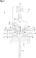
- Figure 1 schematically shows an exemplary embodiment of a removal system 1.
- the removal system 1 comprises a removal head 2 which can be placed on an opening of a bottle 3 which contains a liquid 4.
- a hose 5 is mounted on the removal head 2 and is guided from the removal head 2 into the interior of the bottle 3.
- the extraction head 2 is also connected to a pump 7 via a line 6. Liquid 4 is pumped out of bottle 3 by means of pump 7. The liquid 4 is discharged from the bottle 3 via the hose 5 and then fed to the line 6.
- FIG Figure 1a shows the hose 5 according to FIG Figure 1 .
- an interface 5a for connection 11 to the removal head 2 is actuated.
- the interface 5a is designed as a plastic part and has a bore 20 extending in the longitudinal direction with which the interface 5a is plugged onto the hose 5.
- the plastic part forming the interface 5a has suitable formations 5b on its outer jacket surface, as a result of which an adaptation to the geometry of the removal head 2 is achieved.
- the interface 5a is designed for connection 11 to different extraction heads, that is to say extraction systems 1.
- the Figures 2-4 show a first exemplary embodiment of the removal head 2 according to the invention.
- the removal head 2 has a closure means 8 in the form of a screw cap with which the removal head 2 can be fixed on the opening of a bottle 3.
- the screw cap has an internal thread 9 which can be screwed onto a thread 9 a on the opening of the bottle 3. With the screw cap of the removal head 2, the opening of the bottle 3 is tightly closed.
- the removal head 2 also has a head part 10. At the upper end of the head part 10, a connection 11 is provided, to which the line 6 leading to the pump 7 can be connected. The connection 11 is secured with a check valve 12. The check valve 12 prevents liquid 4 from escaping from the line 6. Furthermore, a ball valve 13 is provided in the head part 10, by means of which an air and pressure equalization in the bottle 3 is effected.
- a guide channel 14 opens out on the underside of the head part 10 and projects into a central recess 27 in the closure means 8, the lower end of the guide channel 14 being secured in the closure means 8 with fastening means 15.
- the guide channel 14 is designed as a hollow cylinder.
- the head part 10 is movable with respect to the screw cap forming the closing means 8, whereby an actuating mechanism is formed.
- a spring 16 is arranged between the head part 10 and the screw cap.
- the head part 10 is held at a distance from the top of the closure means 8 by the spring force of the spring 16 ( Figure 2 ).
- Figure 2 shows the removal head 2 when the actuating mechanism is not actuated.
- the hose 5 is mounted in the interior of the guide channel 14 and secured in position there with locking means.
- the upper end of the hose 5, which can be inserted into the guide channel 14, is provided with a sleeve 17 which forms the interface 5a and which has a recess 5b in the form of a groove 18 running around the circumference.
- the locking means are formed by balls 19 which are guided in bores 20 in the guide channel 14.
- three identical bores 20 are provided in a plane perpendicular to the longitudinal axis of the guide channel 14, each of which is offset from one another by 120 ° in the circumferential direction.
- the bores 20 run in the radial direction in the guide channel 14.
- a ball 19 is guided in each bore 20, with all balls 19 being of identical design.
- the balls 19 are guided in the respective bores 20 with little play.
- the diameter of the bores 20 are slightly tapered in the area of the confluence with the guide channel 14, that is to say slightly smaller than the ball diameter, so that the balls 19 are prevented from falling out into the empty guide channel 14.
- a projection 21 is provided which runs around in the circumferential direction and represents a narrowing of the recess 27 into which the guide channel 14 protrudes.
- This projection 21 forms an adjusting means, wherein Figure 2 the closure means 8 and shows the actuating means in a locked position. This blocking position is assumed when the actuation mechanism is not actuated and the spring 16 keeps the head part 10 at a distance from the closure means 8.
- the projection 21 forming the adjusting means then lies, as Figure 2 shows, in the area of the bores 20.
- the projection thus presses the balls in the bores in the direction of the interior of the guide channel 14, so that the balls 19 are pressed in a locking position with a pressing force against the groove 18 in the cuff 17 of the hose 5, whereby the Hose 5 is fixed in the guide channel 14.
- the head part 10 is pressed against the screw cap forming the closure means 8 and the guide channel 14 is pushed further into the recess 27 of the screw cap.
- the closure means 8 and with it the projection 21 are thus transferred from the blocking position into a release position. In this release position, the projection 21 lies above the bores 20.
- the balls 19 are thus in the release position and are therefore no longer pressed against the hose 5 by means of the projection 21, that is, the hose 5 is no longer held in the guide channel 14. Due to the force of gravity, the hose 5 falls out of the guide channel 14 ( Figure 4 ) and falls into the bottle 3.
- the removal head 2 is attached to the bottle 3.
- the actuation mechanism is not actuated and the hose 5 is firmly held in the guide channel 14 ( Figure 2 ).
- the bottle 3 is then emptied by means of the pump 7.
- the actuation mechanism is activated and the hose 5 in the guide channel 14 is released ( Figure 3 ) so that the tube 5 falls into the empty bottle 3 and can be disposed of.
- the structural unit formed in this way can then be placed on the further bottle 3 for removal of liquid 4.
- Figure 5 shows a second embodiment of the withdrawal head 2 of the withdrawal system 1.
- the tube 5 with the cuff 17 for withdrawing liquid 4 is used as a disposable part, that is to say as a disposable part, for withdrawing liquid 4.
- the hose 5 is coupled to the screw cap forming the closure means 8, so that the hose 5 can be releasably fastened to the removal head 2 with it.
- the hose 5 is automatically released from the removal head 2 when the screw cap is unscrewed.
- Both parts have essentially rotationally symmetrical base bodies.
- the first part 22 is formed essentially as a hollow cylinder.
- a plurality of identically designed engagement elements 24 protrude from the edge at one end face, each of which has a first guide face 25 that forms a curve.
- the second part 23 has projections 26 opening out on its outer jacket surface, which are used for manual actuation of the screw cap.
- projections 26 opening out on its outer jacket surface, which are used for manual actuation of the screw cap.
- recesses 27 opening out at an end face are provided, each recess 27 having a second guide surface 28 corresponding to the respective first guide surface 25 of an engagement element 24, that is, a second guide surface 28 configured in a complementary manner.
- the first and second parts 22, 23 are rotated towards one another to form the closure means 8, so that the first guide surfaces 25 of the engagement elements 24 are in contact with the second guide surfaces 28 of the recess 27.
- the parts of the closure means 8 can thus be moved between a blocking position and a release position.
- first guide surfaces 25 of the engagement elements 24 lie over their entire surface on the second guide surfaces 28 of the recesses 27, so that the end faces of the first and second parts 22, 23 lie close to one another, as in FIG Figure 5 shown.
Abstract
Die Erfindung betrifft einen Schlauch für ein Entnahmesystem (1) mit einer Schnittstelle 5a zur lösbaren Verbindung an einem Entnahmekopf (2) des Entnahmesystems (1), so dass der Schlauch (5) als Einwegteil für eine Entnahme von Flüssigkeit aus einem Behälter nutzbar ist.The invention relates to a hose for a withdrawal system (1) with an interface 5a for detachable connection to a withdrawal head (2) of the withdrawal system (1) so that the hose (5) can be used as a disposable part for withdrawing liquid from a container.
Description
Die Erfindung betrifft einen Schlauch für ein Entnahmesystem und ein Verfahren zur Entnahme von Flüssigkeit aus einem Behälter mittels eines Entnahmesystems.The invention relates to a hose for a withdrawal system and a method for withdrawing liquid from a container by means of a withdrawal system.
Derartige Entnahmesysteme umfassen Flaschen, in welchen Flüssigkeiten wie Chemikalien gelagert sind, wo sie Entnahmeköpfe, die auf den Öffnungen der Flaschen befestigt werden können, wobei die Entnahmeköpfe hierfür geeignete Verschlussmittel aufweisen. Derartige Flaschen werden beispielsweise in Laboren eingesetzt.Such dispensing systems include bottles in which liquids such as chemicals are stored, where they have dispensing heads that can be attached to the openings of the bottles, the dispensing heads having suitable closure means for this purpose. Such bottles are used, for example, in laboratories.
Bei bekannten Entnahmesystemen dieser Art ist der Entnahmekopf in Form eines einfachen Deckels ausgebildet, und in welchen ein Schlauch gesteckt und in den Innenraum der zugeordneten Flasche geführt wird. Der Schlauch wird dann an eine Pumpe angeschlossen, um Flüssigkeit aus dem Behälter abzupumpen.In known extraction systems of this type, the extraction head is designed in the form of a simple cover and into which a hose is inserted and guided into the interior of the associated bottle. The hose is then connected to a pump to pump liquid out of the container.
Sobald die Flasche geleert wird, wird der Schlauch aus dem Deckel herausgezogen und gegebenenfalls für die Entnahme von Flüssigkeit aus einer weiteren Flasche verwendet.As soon as the bottle is emptied, the tube is pulled out of the lid and, if necessary, used to remove liquid from another bottle.
Alternativ kann der Schlauch während des Wechselns auch durch den Deckel hindurch geführt bleiben. Der Deckel wird dann auf einer neuen Flasche befestigt.Alternatively, the hose can also remain guided through the cover during the change. The lid is then attached to a new bottle.
Ein erster Nachteil eines derartigen Entnahmesystems besteht darin, dass die Bohrung im Deckel, durch welche der Schlauch geführt ist, keinen dichten Abschluss bildet. Daher können dort Dämpfe der in der Flasche gelagerten Flüssigkeit austreten, was insbesondere dann kritisch ist, wenn in der Flasche giftige Chemikalien gelagert sind.A first disadvantage of such a removal system is that the hole in the cover through which the hose is passed does not seal Completion forms. Therefore, vapors from the liquid stored in the bottle can escape there, which is particularly critical when toxic chemicals are stored in the bottle.
Ein weiterer Nachteil besteht darin, dass der aus der leeren Flasche herausgezogene Schlauch die Flüssigkeit in der nächsten Flasche, in die er eingeführt wird, kontaminiert, da an diesem noch Flüssigkeitsreste der Flüssigkeit in der ersten Flasche anhaften.Another disadvantage is that the tube pulled out of the empty bottle contaminates the liquid in the next bottle into which it is inserted, since liquid residues from the liquid in the first bottle are still adhering to it.
Desweiteren kann bei Herausziehen des Schlauches ein Bediener Flüssigkeitsresten ausgesetzt werden, bedingt durch ein Nachtropfen von Flüssigkeitsresten aus dem Schlauch.Furthermore, when the hose is pulled out, an operator can be exposed to liquid residues, caused by liquid residues dripping from the hose.
Aus der
Derartige mit Tauchrohren arbeitenden Entnahmesysteme können nur für größere Behälter wie Fässer eingesetzt werden, nicht jedoch zur Entnahme von Flüssigkeiten aus Flaschen.Such extraction systems working with dip tubes can only be used for larger containers such as barrels, but not for the extraction of liquids from bottles.
Bei einem Einsatz des Entnahmesystems für Flaschen wären bauliche Änderungen vorzunehmen, welche die Transportzulassung beeinträchtigen würden, die für eine Entnahme von Flüssigkeiten aus den Flaschen erforderlich ist.When using the extraction system for bottles, structural changes would have to be made, which would affect the transport authorization, which is necessary for the extraction of liquids from the bottles.
Der Erfindung liegt die Aufgabe zugrunde, ein Entnahmesystem der eingangsgenannten Art so auszubilden, dass dieses bei einfachem konstruktivem Aufbau eine hohe Funktionalität aufweist.The invention is based on the object of designing an extraction system of the type mentioned at the outset in such a way that it has a high level of functionality with a simple structural design.
Zur Lösung dieser Aufgabe sind die Merkmale unabhängiger Ansprüche vorgesehen. Vorteilhafte Ausführungsformen und zweckmäßige Weiterbildungen der Erfindung sind in den abhängigen Ansprüchen beschrieben.The features of independent claims are provided to solve this problem. Advantageous embodiments and expedient developments of the invention are described in the dependent claims.
Die Erfindung betrifft einen Schlauch für ein Entnahmesystem mit einer Schnittstelle zur lösbaren Verbindung an einem Entnahmekopf des Entnahmesystems, so dass der Schlauch als Einwegteil für eine Entnahme von Flüssigkeit aus einem Behälter nutzbar ist.The invention relates to a hose for a withdrawal system with an interface for a detachable connection to a withdrawal head of the withdrawal system, so that the hose can be used as a disposable part for withdrawing liquid from a container.
Der Grundgedanke der Erfindung besteht somit darin, den Schlauch zur Entnahme von Flüssigkeit aus einem Behälter, oder auch zur Befüllung des Behälters als Einwegteil, das heißt als Wegwerfteil zu konzipieren.The basic idea of the invention is thus to design the hose for removing liquid from a container, or also for filling the container, as a disposable part, that is to say as a disposable part.
Hierzu weist der Schlauch eine geeignete Schnittstelle auf, mittels derer der Schlauch lösbar mit dem Entnahmekopf eines Entnahmesystems verbunden werden kann.For this purpose, the hose has a suitable interface, by means of which the hose can be detachably connected to the extraction head of an extraction system.
Zur Entnahme von Flüssigkeit wird der Schlauch mit dem Entnahmekopf verbunden und der Entnahmekopf wird mit einem Verschlussmittel als Bestandteil des Entnahmekopfs am Behälter fixiert. Nach der Entnahme von Flüssigkeit, wird der Schlauch vom Entnahmekopf gelöst und kann mit der Flasche entsorgt werden. Prinzipiell ist das erfindungsgemäße Entnahmesystem auch zur Befüllung von Behältern geeignet.To remove liquid, the hose is connected to the removal head and the removal head is fixed to the container with a closure means as part of the removal head. After the liquid has been withdrawn, the hose is detached from the withdrawal head and can be disposed of with the bottle. In principle, the removal system according to the invention is also suitable for filling containers.
Der erfindungsgemäße Schlauch mit dem Entnahmesystem kann für unterschiedliche Behälter genutzt werden. Besonders vorteilhaft können die Behälter von Flaschen oder Kanistern gebildet sein, auf welche ohne Beschränkung der Allgemeinheit im Folgenden Bezug genommen wird.The hose according to the invention with the extraction system can be used for different containers. The containers can particularly advantageously be formed by bottles or canisters, to which reference is made below without restricting the generality.
Der Schlauch mit der Schnittstelle bildet eine kostengünstige, rationell herstellbare Einheit, die als modulare Einheit in einem Entnahmesystem eingesetzt werden kann.The hose with the interface forms a cost-effective, economically producible unit that can be used as a modular unit in a removal system.
Besonders vorteilhaft ist die Schnittstelle zum Anschluss an unterschiedliche Entnahmeköpfe ausgebildet.The interface is particularly advantageously designed for connection to different extraction heads.
Damit bildet der Schlauch mit seiner Schnittstelle eine modulare Einheit, die durch die Anschlussmöglichkeit an unterschiedliche Entnahmesysteme flexibel und in einem breiten Anwendungsbereich einsetzbar ist.The hose and its interface thus form a modular unit, which can be used flexibly and in a wide range of applications thanks to the possibility of connecting to different extraction systems.
Weiter vorteilhaft ist die Schnittstelle von einem auf dem Schlauch befestigten Kunststoffteil gebildet.The interface is also advantageously formed by a plastic part fastened to the hose.
Die Schnittstelle kann somit kostengünstig und rationell in Form eines Kunststoff-Spritzgussteils hergestellt werden.The interface can thus be produced inexpensively and efficiently in the form of a plastic injection-molded part.
Die Erfindung betrifft weiterhin ein Verfahren zur Entnahme von Flüssigkeit aus einem Behälter mittels eines Entnahmesystems.The invention also relates to a method for withdrawing liquid from a container by means of a withdrawal system.
Ein wesentlicher Vorteil der Erfindung besteht somit darin, dass mit dem Schlauch als am Entnahmekopf lösbar befestigtes Wegwerfteil Kontaminationen bei einer Mehrfachverwendung des Entnahmekopfes auf einfache Weise vermieden werden können. Der am Entnahmekopf befestigte Schlauch wird nur einmalig zum Entleeren einer Flasche verwendet und dann durch Betätigen des Betätigungsmechanismus am Entnahmekopf in dieser Flasche belassen. Dadurch wird vermieden, dass mit diesem Schlauch die Flüssigkeit in der nächsten zu entleerenden Flasche kontaminiert wird, da für diese ein neuer Schlauch am Entnahmekopf befestigt wird. Damit wird ein kontaminierungsfreies Verfahren zum Entleeren von Flaschen bereitgestellt. Die auswechselbaren Schläuche sind äußerst kostengünstig, wobei diese insbesondere aus Kunststoffteilen bestehen. Generell können die Schläuche auch aus anderen Materialien bestehen, wie zum Beispiel VA. Die Verwendung separater Schläuche zum Entleeren der Flaschen führt daher zu keiner nennenswerten Erhöhung der Herstellkosten des Entnahmesystems.An essential advantage of the invention is therefore that with the hose as a disposable part detachably attached to the removal head, contamination can be avoided in a simple manner when the removal head is used multiple times. The hose attached to the removal head is only used once to empty a bottle and then left in this bottle by actuating the actuation mechanism on the removal head. This prevents the liquid in the next bottle to be emptied from being contaminated with this hose, since a new hose is attached to the sampling head for this. This provides a contamination-free method for emptying bottles. The exchangeable hoses are extremely inexpensive, and they consist in particular of plastic parts. In general, the hoses can too consist of other materials, such as VA. The use of separate hoses for emptying the bottles therefore does not lead to any significant increase in the production costs of the extraction system.
Gemäß einer vorteilhaften Ausgestaltung der Erfindung weist der Entnahmekopf Verriegelungsmittel auf, welche in einer Verriegelungsposition den Schlauch im Entnahmekopf fixieren. Mittels des Betätigungsmechanismus sind die Verriegelungsmittel in eine Löseposition überführbar, in welcher diese den Schlauch freigeben.According to an advantageous embodiment of the invention, the removal head has locking means which fix the tube in the removal head in a locking position. By means of the actuating mechanism, the locking means can be transferred into a release position in which they release the hose.
Die Verriegelungsmittel stellen mechanische Einheiten dar, die durch die Betätigung des Betätigungsmechanismus von der Verriegelungsposition in die Löseposition oder umgekehrt überführt werden können.The locking means represent mechanical units which can be transferred from the locking position to the release position or vice versa by actuating the actuating mechanism.
Besonders vorteilhaft ist der Betätigungsmechanismus eine rein mechanische Einheit, mit dem Betätigungsbewegungen generiert werden, die direkt auf die Verrieglungsmittel umgesetzt werden können.The actuation mechanism is particularly advantageously a purely mechanical unit with which actuation movements are generated that can be implemented directly on the locking means.
Damit wird ein konstruktiv einfacher Verrieglungs- und Entriegelungsmechanismus für den Schlauch geschaffen.This creates a structurally simple locking and unlocking mechanism for the hose.
Gemäß einer konstruktiv vorteilhaften Ausgestaltung der Erfindung sind die Verriegelungsmittel von Kugeln gebildet, die in Bohrungen eines Führungskanals verschiebbar gelagert sind. In dem Führungskanal ist der Schlauch führbar. In der Verriegelungsposition sind die Kugeln mit einer Anpresskraft gegen den Schlauch gedrückt, wodurch der Schlauch lagefixiert ist. In der Löseposition sind die Kugeln vom Schlauch gelöst.According to a structurally advantageous embodiment of the invention, the locking means are formed by balls which are slidably mounted in bores of a guide channel. The hose can be guided in the guide channel. In the locking position, the balls are pressed against the hose with a pressing force, whereby the hose is fixed in position. In the release position, the balls are released from the hose.
Diese Verriegelungsmittel sind konstruktiv einfach ausgeführt und gewährleisten eine sichere Verrieglung und Entriegelung des Schlauchs.These locking means are designed to be simple in construction and ensure safe locking and unlocking of the hose.
Besonders vorteilhaft sind in dem Führungskanal in Umfangsrichtung äquidistant angeordnete, in radialer Richtung verlaufende Bohrungen vorgesehen, wobei in jeder Bohrung eine Kugel geführt ist. Die Bohrungen und Kugeln sind jeweils identisch ausgebildet und in einer senkrecht zur Längsachse des Führungskanals verlaufenden Ebene orientiert.Particularly advantageously, bores arranged equidistantly in the circumferential direction and extending in the radial direction are provided in the guide channel, a ball being guided in each bore. The bores and balls are each designed identically and oriented in a plane running perpendicular to the longitudinal axis of the guide channel.
Da die Kugeln zum Verriegeln des Schlauchs in den Bohrungen in radialer Richtung und damit direkt auf den Schlauch zubewegt werden, ergibt eine gute Kraftübertragung von den Kugeln auf den Schlauch und somit eine sichere Verriegelung.Since the balls for locking the hose in the bores are moved in the radial direction and thus directly towards the hose, there is good power transmission from the balls to the hose and thus a secure locking.
Durch die identische Ausbildung der Bohrungen, den Kugeln und deren drehsymmetrischen Anordnung im Führungskanal und damit relativ zum Schlauch, ergibt sich eine allseitig gleiche Kraftübertragung auf den Schlauch, wodurch eine besonders effiziente, sichere Verriegelung erzielt wird.The identical design of the bores, the balls and their rotationally symmetrical arrangement in the guide channel and thus relative to the hose results in the same power transmission to the hose on all sides, which results in a particularly efficient, secure locking.
Weiter vorteilhaft ist jede Bohrung an ihrer Ausmündung in den Führungskanal auf einen Durchmesser, der kleiner als der Durchmesser der im Führungskanal geführten Kugeln ist, verengt.It is also advantageous that each bore is narrowed at its opening into the guide channel to a diameter which is smaller than the diameter of the balls guided in the guide channel.
Dadurch wird auf einfache Weise ein Herausfallen der Kugeln aus den Bohrungen verhindert, wenn der Schlauch aus dem Führungskanal herausgelöst wurde und der Führungskanal somit leer ist.This prevents the balls from falling out of the bores in a simple manner when the hose has been detached from the guide channel and the guide channel is thus empty.
Gemäß einer vorteilhaften Ausgestaltung der Erfindung ist der Führungskanal relativ zum Verschlussmittel bewegbar.According to an advantageous embodiment of the invention, the guide channel can be moved relative to the closure means.
Generell kann der Führungskanal Bestandteil eines gegenüber dem Verschlussmittel beweglichen Kopfteils sein.In general, the guide channel can be part of a head part that is movable with respect to the closure means.
Bei dieser Ausführungsform drücken in einer Sperrstellung des Verschlussmittels relativ zum Führungskanal Stellmittel am Verschlussmittel die Verrieglungsmittel in den Bohrungen gegen den Schlauch und fixieren diesen im Führungskanal. In einer Freigabestellung des Verschlussmittels sind relativ zum Führungskanal die Stellmittel außer Eingriff mit den Verriegelungsmitteln, sodass der Schlauch aus dem Führungskanal gelöst ist.In this embodiment, in a blocking position of the closure means, actuating means press on the closure means relative to the guide channel the locking means in the bores against the hose and fix it in the guide channel. In a release position of the closure means, the adjusting means are out of engagement with the locking means relative to the guide channel, so that the hose is released from the guide channel.
Die Stellmittel sind bevorzugt am Verschlussmittel angeordnet. Beispielsweise können als Stellmittel Vorsprünge, Rastschultern oder Rastnasen vorgesehen sein, die insbesondere Bestandteil des Verschlussmittels sein können und einstückig mit diesem ausgebildet sein können. Derartige Stellmittel weisen einen besonders einfachen Aufbau auf. Weiterhin wird mit diesen eine besonders einfache und direkte Ankopplung des Betätigungsmechanismus an die Verriegelungsmittel realisiert.The adjusting means are preferably arranged on the closure means. For example, projections, locking shoulders or locking lugs can be provided as adjusting means, which in particular can be part of the closure means and can be formed in one piece with it. Such adjusting means have a particularly simple structure. Furthermore, a particularly simple and direct coupling of the actuating mechanism to the locking means is realized with these.
Generell werden die Stellmittel durch den Betätigungsmechanismus gesteuert. Dies erfolgt besonders einfach derart, dass dann wenn der Betätigungsmechanismus nicht durch einen Benutzer betätigt ist, die Stellmittel in der Sperrstellung des Verschlussmittels für eine Fixierung des Schlauchs sorgen. Durch ein Betätigen des Betätigungsmechanismus sind die Stellmittel außer Eingriff mit den Verriegelungsmitteln gebracht.In general, the actuating means are controlled by the actuating mechanism. This is done in a particularly simple manner in such a way that when the actuating mechanism is not actuated by a user, the adjusting means ensure that the hose is fixed in the blocking position of the closure means. By actuating the actuating mechanism, the actuating means are disengaged from the locking means.
Vorteilhaft ist der Betätigungsmechanismus ein Federmechanismus. In diesem Fall ist das Kopfteil durch die Federkraft einer Feder in der Sperrstellung relativ zum Verschlussmittel gehalten. Das Überführen in die Freigabestellung erfolgt durch Andrücken des Kopfteils auf das Verschlussmittel gegen die Federkraft der Feder.The actuating mechanism is advantageously a spring mechanism. In this case, the head part is held in the blocking position relative to the closure means by the spring force of a spring. The transfer into the release position takes place by pressing the head part onto the locking means against the spring force of the spring.
Das Funktionsprinzip ist somit derart, dass die Federkraft der Feder für eine Fixierung des Schlauchs am Entnahmekopf sorgt. Zum Lösen des Schlauchs muss ein Benutzer den Betätigungsmechanismus betätigen, indem er das Kopfteil gegen das Verschlussmittel drückt. Ebenso kann auf diese Weise ein neuer Schlauch am Entnahmekopf fixiert werden.The functional principle is thus such that the spring force of the spring ensures that the hose is fixed on the extraction head. To release the hose, a user must actuate the actuation mechanism by pressing the head part against the closure means. A new hose can also be fixed to the extraction head in this way.
Gemäß einer weiteren Variante der Erfindung weist das Verschlussmittel zwei Teile auf, die relativ zueinander in eine Sperrstellung bewegt werden können, in welcher der Schlauch am Entnahmekopf fixiert ist und die relativ zueinander in eine Lösestellung bewegt werden können, in welcher der Schlauch vom Entnahmekopf gelöst ist.According to a further variant of the invention, the closure means has two parts which can be moved relative to one another into a blocking position in which the hose is fixed on the removal head and which can be moved relative to one another into a release position in which the hose is released from the removal head .
Ein wesentlicher Vorteil dieser Variante besteht darin, dass zum Lösen des Schlauchs zum Entnahmekopf keine separate Betätigung von Betätigungsmitteln erforderlich ist. Vielmehr wird bei Öffnen des Verschlussmittels, um den Entnahmekopf vom Behälter zu lösen, der Schlauch gleichzeitig vom Entnahmekopf gelöst, sodass dieser in den geleerten Behälter fallen kann.A major advantage of this variant is that no separate actuation of actuating means is required to release the hose to the removal head. Rather, when the closure means is opened, in order to detach the removal head from the container, the hose is released from the removal head at the same time, so that it can fall into the emptied container.
Dies stellt einerseits eine rationelle Ausgestaltung des Entnahmesystems dar, da auf eine Konstruktion separater Bestätigungsmittel verzichtet werden kann. Weiterhin wird dadurch die Funktionalität und Betriebssicherheit des Entnahmesystems verbessert. Eine Bedienperson muss nicht mehr daran denken, einen Betätigungsmechanismus zu betätigen und der Schlauch vom Entnahmekopf zu lösen. Vielmehr erfolgt dies automatisch und selbsttätig bei Öffnen des Verschlussmittels.On the one hand, this represents a rational design of the removal system, since there is no need to construct separate confirmation means. This also improves the functionality and operational safety of the extraction system. An operator no longer has to think about actuating an actuating mechanism and detaching the hose from the removal head. Rather, this takes place automatically and automatically when the closure means is opened.
Gemäß einer konstruktiv vorteilhaften Ausgestaltung weist das Verschlussmittel zwei Teile auf, die relativ zueinander in eine Sperrstellung bewegt werden können, in welcher der Schlauch am Entnahmekopf fixiert ist, und die relativ zueinander in eine Lösestellung bewegt werden können, in welcher der Schlauch vom Entnahmekopf gelöst ist.According to a structurally advantageous embodiment, the closure means has two parts which can be moved relative to one another into a blocking position in which the hose is fixed on the removal head, and which can be moved relative to one another into a release position in which the hose is released from the removal head .
Dabei werden bei Öffnen des Verschlussmittels zum Ablösen des Entnahmekopfs vom Behälter die Teile des Verschlussmittels selbsttätig in die Lösestellung überführt.When the closure means is opened to detach the removal head from the container, the parts of the closure means are automatically transferred into the release position.
Damit wird auf konstruktiv einfache Weise eine lösbare Fixierung des Schlauchs am Entnahmekopf realisiert, wobei insbesondere bei Öffnen des Verschlussmittels der Schlauch selbsttätig vom Entnahmekopf gelöst wird.A releasable fixation of the hose on the removal head is thus realized in a structurally simple manner, the hose being automatically detached from the removal head, in particular when the closure means is opened.
Gemäß einer konstruktiv besonders einfachen und robusten Ausgestaltung weist das erste Teil des Verschlussmittels über eine seiner Stirnseiten hervorstehende Eingriffssegmente mit jeweils ersten Führungsflächen auf. Das zweite Teil des Verschlussmittels weist an einer seiner Stirnseite ausmündende Aussparungen mit zweiten Führungsflächen auf. Bei Überführen zwischen der Lösestellung und der Sperrstellung wird das erste Teil gegen das zweite Teil bewegt, in dem die ersten Führungsflächen an den zweiten Führungsflächen bewegt werden.According to a structurally particularly simple and robust embodiment, the first part of the closure means has engagement segments protruding over one of its end faces, each with first guide surfaces. The second part of the closure means has recesses with second guide surfaces opening out on one of its end faces. When transferring between the release position and the blocking position, the first part is moved against the second part by moving the first guide surfaces on the second guide surfaces.
Dabei liegen in der Sperrstellung die Stirnseiten der Teile dicht aneinander. In der Lösestellung sind die Teile voneinander abgehoben.The front sides of the parts lie close to one another in the locked position. In the release position, the parts are lifted from one another.
Die Führungsflächen der Eingriffssegmente und der Aussparungen sorgen für eine reibungsarme, kontrollierte Bewegbarkeit der Teile der Verschlussmittel zueinander.The guide surfaces of the engagement segments and the recesses ensure low-friction, controlled movability of the parts of the closure means with respect to one another.
Besonders vorteilhaft ist das Verschlussmittel im Schraubverschluss.The closure means in the screw closure is particularly advantageous.
In diesem Fall werden bei Aufschrauben des Schraubverschlusses die Teile des Verschlussmittels in die Lösestellung überführt.In this case, when the screw cap is unscrewed, the parts of the closure means are transferred into the release position.
Der Schraubverschluss zeichnet sich durch eine besonders einfache Handhabbarkeit aus.The screw cap is particularly easy to handle.
Die Erfindung wird im Folgenden anhand der Zeichnungen erläutert. Es zeigen:
- Figur 1:
- Schematische Darstellung eines Entnahmesystems.
- Figur 1a:
- Einzeldarstellung des erfindungsgemäßen Schlauchs für das
Entnahmesystem gemäß Figur 1 . - Figur 2:
- Erstes Beispiel eines Entnahmekopfs des Entnahmesystems gemäß
Figur 1 mit darin verriegeltem Schlauch. - Figur 3:
- Entnahmekopf des Entnahmesystems gemäß
Figur 2 mit darin angeordnetem, entriegeltem Schlauch. - Figur 4:
- Entnahmekopf des Entnahmesystems gemäß
Figur 2 mit aus dem Entnahmekopf herausfallendem Schlauch. - Figur 5:
- Zweites Beispiel eines Entnahmekopfs des Entnahmesystems gemäß
Figur 1 - Figur 6:
- Einzeldarstellung der Komponenten des Verschlussmittels des Entnahmekopfs gemäß
Figur 5
- Figure 1:
- Schematic representation of a withdrawal system.
- Figure 1a:
- Individual representation of the hose according to the invention for the extraction system according to FIG
Figure 1 . - Figure 2:
- First example of a removal head of the removal system according to
Figure 1 with the hose locked in it. - Figure 3:
- Withdrawal head of the withdrawal system according to
Figure 2 with the unlocked hose arranged in it. - Figure 4:
- Withdrawal head of the withdrawal system according to
Figure 2 with hose falling out of the sampling head. - Figure 5:
- Second example of a removal head of the removal system according to FIG
Figure 1 . - Figure 6:
- Individual representation of the components of the closure means of the removal head according to
Figure 5 .
Das Entnahmesystem 1 umfasst einen Entnahmekopf 2, der auf eine Öffnung einer Flasche 3 aufsetzbar ist, die eine Flüssigkeit 4 enthält. Am Entnahmekopf 2 ist ein Schlauch 5 gelagert, der vom Entnahmekopf 2 in den Innenraum der Flasche 3 geführt ist.The
Der Entnahmekopf 2 ist weiterhin über eine Leitung 6 an eine Pumpe 7 angeschlossen. Mittels der Pumpe 7 wird Flüssigkeit 4 aus der Flasche 3 abgepumpt. Die Flüssigkeit 4 wird über den Schlauch 5 aus der Flasche 3 ausgeführt und dann der Leitung 6 zugeführt.The
Die
Der Entnahmekopf 2 weist weiterhin ein Kopfteil 10 auf. Am oberen Ende des Kopfteils 10 ist ein Anschluss 11 vorgesehen, an welchen die zur Pumpe 7 führende Leitung 6 angeschlossen werden kann. Der Anschluss 11 ist mit einem Rückschlagventil 12 gesichert. Das Rückschlagventil 12 verhindert, dass Flüssigkeit 4 aus der Leitung 6 austritt. Weiterhin ist im Kopfteil 10 ein Kugelventil 13 vorgesehen, mittels dessen ein Luft- und Druckausgleich in der Flasche 3 bewirkt wird.The
An der Unterseite des Kopfteils 10 mündet ein Führungskanal 14 aus, der in eine zentrale Aussparung 27 im Verschlussmittel 8 ragt, wobei das untere Ende des Führungskanals 14 mit Befestigungsmitteln 15 im Verschlussmittel 8 gesichert ist. Der Führungskanal 14 ist hohlzylindrisch ausgebildet.A
Das Kopfteil 10 ist gegenüber dem das Verschlussmittel 8 bildenden Schraubverschluss beweglich, wodurch ein Betätigungsmechanismus gebildet wird.The
Zwischen dem Kopfteil 10 und dem Schraubverschluss ist eine Feder 16 angeordnet. Durch die Federkraft der Feder 16 wird das Kopfteil 10 auf Abstand zur Oberseite des Verschlussmittels 8 gehalten (
Wie aus den
Die Verriegelungsmittel sind von Kugeln 19 gebildet, die in Bohrungen 20 im Führungskanal 14 geführt sind. Im vorliegenden Fall sind in einer Ebene senkrecht zur Längsachse des Führungskanals 14 drei identische Bohrungen 20 vorgesehen, die jeweils um 120° in Umfangsrichtung zueinander versetzt angeordnet sind. Die Bohrungen 20 verlaufen in radialer Richtung im Führungskanal 14. In jeder Bohrung 20 ist eine Kugel 19 geführt, wobei alle Kugeln 19 identisch ausgebildet sind. Die Kugeln 19 sind mit geringem Spiel in den jeweiligen Bohrungen 20 geführt.The locking means are formed by
Die Durchmesser der Bohrungen 20 sind im Bereich der Einmündung in den Führungskanal 14 etwas verjüngt, das heißt etwas kleiner als der Kugeldurchmesser, sodass ein herausfallen der Kugeln 19 in den leeren Führungskanal 14 verhindert wird.The diameter of the
Wie aus den
Wird der Betätigungsmechanismus, wie in
Zum Entleeren der Flasche 3 wird der Entnahmekopf 2 auf der Flasche 3 befestigt. Der Betätigungsmechanismus ist nicht betätigt und der Schlauch 5 ist fest im Führungskanal 14 gehalten (
Soll der Entnahmekopf 2 zur Entnahme von Flüssigkeit 4 aus einer weiteren Flasche 3 verwendet werden, wird zunächst ein neuer Schlauch 5 imIf the
Führungskanal 14 des Entnahmekopfs 2 befestigt. Hierzu betätigt ein Benutzer den Betätigungsmechanismus und schiebt dann den Schlauch 5 in den Führungskanal 14. Dann lässt der Benutzer das Kopfteil 10 los, sodass das Kopfteil 10 durch die Federkraft der Feder 16 vom Verschlussmittel 8 abgehoben wird. Damit wird das Verschlussmittel 8 mit dessen Vorsprung 21 in die Sperrstellung überführt, wodurch der Schlauch 5 im Führungskanal 14 festgehalten wird.
Die so gebildete Baueinheit kann dann für eine Entnahme von Flüssigkeit 4 auf die weitere Flasche 3 aufgesetzt werden.The structural unit formed in this way can then be placed on the
Der Schlauch 5 ist in diesem Fall an den das Verschlussmittel 8 bildenden Schraubverschluss angekoppelt, so dass mit diesem der Schlauch 5 lösbar am Entnahmekopf 2 befestigbar ist. Insbesondere wird der Schlauch 5 bei Aufschrauben des Schraubverschlusses selbsttätig vom Entnahmekopf 2 gelöst.In this case, the
Wie
Beide Teile weisen im wesentlichen rotationssymmetrische Grundkörper auf.Both parts have essentially rotationally symmetrical base bodies.
Das erste Teil 22 ist im wesentlichen hohlzylindrisch ausgebildet. Von dem Rand an einer Stirnfläche stehen mehrere identisch ausgebildete Eingriffselemente 24 hervor, die jeweils eine Kurvenform ausbildende erste Führungsfläche 25 aufweisen.The
Das zweite Teil 23 weist an seiner äußeren Mantelfläche ausmündende Vorsprünge 26 auf, die zur manuellen Betätigung des Schraubverschlusses dienen. Innerhalb des Grundkörpers des ersten Teils 22 sind an einer Stirnfläche ausmündende Aussparungen 27 vorgesehen, wobei jede Aussparung 27 eine zur jeweils ersten Führungsfläche 25 eines Eingriffselements 24 korrespondierende, das heißt komplementär ausgebildete zweite Führungsfläche 28 aufweist.The
Das erste und zweite Teil 22, 23 werden zur Ausbildung des Verschlussmittels 8 aufeinander gedreht, so dass die ersten Führungsflächen 25 der Eingriffselemente 24 in Kontakt mit den zweiten Führungsflächen 28 der Aussparung 27 sind. So können die Teile des Verschlussmittels 8 zwischen einer Sperrstellung und einer Lösestellung bewegt werden.The first and
In der Sperrstellung liegen die ersten Führungsflächen 25 der Eingriffselemente 24 vollflächig auf den zweiten Führungsflächen 28 der Aussparungen 27, so dass durch die Stirnseiten des ersten und zweiten Teils 22, 23 dicht aneinander liegen, wie in
In dieser Sperrstellung ist der an der Innenseite des Gewindes 9a anliegende Schlauch 5 mit einer Manschette 17 am Entnahmekopf 2 fixiert.In this blocking position, the
Bei Aufschrauben des Schraubverschlusses werden die Teile 22, 23 voneinander abgehoben, in dem die ersten Führungsflächen 25 entlang der zweiten Führungsfläche gleiten 28. Ist der Schraubverschluss soweit aufgeschraubt, dass die Teile 22, 23 in ihrer Lösestellung sind, ist der Schlauch 5 freigegeben und er fällt in die Flasche 3.When the screw cap is unscrewed, the
- (1)(1)
- EntnahmesystemWithdrawal system
- (2)(2)
- EntnahmekopfExtraction head
- (3)(3)
- Flaschebottle
- (4)(4)
- Flüssigkeitliquid
- (5)(5)
- Schlauchhose
- (5a)(5a)
- Schnittstelleinterface
- (5b)(5b)
- AusformungShaping
- (6)(6)
- Leitungmanagement
- (7)(7)
- Pumpepump
- (8)(8th)
- VerschlussmittelClosure means
- (9)(9)
- Innengewindeinner thread
- (9a)(9a)
- Gewindethread
- (10)(10)
- KopfteilHeadboard
- (11)(11)
- Anschlussconnection
- (12)(12)
- Rückschlagventilcheck valve
- (13)(13)
- KugelventilBall valve
- (14)(14)
- FührungskanalGuide channel
- (15)(15)
- BefestigungsmittelFasteners
- (16)(16)
- Federfeather
- (17)(17)
- Manschettecuff
- (18)(18)
- NutGroove
- (19)(19)
- KugelBullet
- (20)(20)
- Bohrungdrilling
- (21)(21)
- Vorsprunghead Start
- (22)(22)
- Erstes TeilFirst part
- (23)(23)
- Zweites TeilSecond part
- (24)(24)
- EingriffselementEngagement element
- (25)(25)
- Erste FührungsflächeFirst guide surface
- (26)(26)
- Vorsprunghead Start
- (27)(27)
- AussparungRecess
- (28)(28)
- Zweite FührungsflächeSecond guide surface
Claims (15)
Priority Applications (5)
| Application Number | Priority Date | Filing Date | Title |
|---|---|---|---|
| EP20158022.2A EP3868704A1 (en) | 2020-02-18 | 2020-02-18 | Hose for a removal system and method for removing liquid from a container by means of a removal system |
| US17/130,104 US11655135B2 (en) | 2020-02-18 | 2020-12-22 | Tube for a withdrawal system and method for withdrawing a fluid from a container via a withdrawal system |
| TW109145545A TW202134132A (en) | 2020-02-18 | 2020-12-22 | Tube for a removal system and method for removing fluid from a container by means of a removal system |
| CN202011548181.3A CN113335751A (en) | 2020-02-18 | 2020-12-24 | Hose for an extraction system and method for extracting a liquid from a container by means of an extraction system |
| KR1020210020403A KR102635033B1 (en) | 2020-02-18 | 2021-02-16 | Tube for a removal system and method for removing fluid from a container by means of a removal system |
Applications Claiming Priority (1)
| Application Number | Priority Date | Filing Date | Title |
|---|---|---|---|
| EP20158022.2A EP3868704A1 (en) | 2020-02-18 | 2020-02-18 | Hose for a removal system and method for removing liquid from a container by means of a removal system |
Publications (1)
| Publication Number | Publication Date |
|---|---|
| EP3868704A1 true EP3868704A1 (en) | 2021-08-25 |
Family
ID=69810516
Family Applications (1)
| Application Number | Title | Priority Date | Filing Date |
|---|---|---|---|
| EP20158022.2A Pending EP3868704A1 (en) | 2020-02-18 | 2020-02-18 | Hose for a removal system and method for removing liquid from a container by means of a removal system |
Country Status (5)
| Country | Link |
|---|---|
| US (1) | US11655135B2 (en) |
| EP (1) | EP3868704A1 (en) |
| KR (1) | KR102635033B1 (en) |
| CN (1) | CN113335751A (en) |
| TW (1) | TW202134132A (en) |
Families Citing this family (2)
| Publication number | Priority date | Publication date | Assignee | Title |
|---|---|---|---|---|
| BE1026635B1 (en) * | 2018-09-20 | 2020-04-21 | Anheuser Busch Inbev Sa | Kit for dispensing a beverage through a dispensing tube that includes a dispensing valve |
| ES2874330T3 (en) * | 2018-11-12 | 2021-11-04 | Micro Matic As | Dispensing head and beverage dispensing system |
Citations (5)
| Publication number | Priority date | Publication date | Assignee | Title |
|---|---|---|---|---|
| US5836364A (en) * | 1995-12-29 | 1998-11-17 | Burton; John W. | Refillable pressurized beverage container |
| WO2006000437A1 (en) * | 2004-06-25 | 2006-01-05 | Impress Group B.V. | Disposable tap for a pressurized liquid container |
| WO2011100937A1 (en) * | 2010-02-19 | 2011-08-25 | Budich International Gmbh | Safety connection system having a safety threaded closure for an active ingredient container and having a mating coupling, and water disinfecting device |
| DE102010049024A1 (en) * | 2010-10-21 | 2012-04-26 | Hw Brauerei-Service Gmbh | Valve assembly for beverage container, particularly for barrel or keg, has valve body, which is inserted into container and has two valve seats, and two closure elements |
| EP2848583B1 (en) | 2013-09-12 | 2016-05-25 | as Strömungstechnik GmbH | Retrieval system |
Family Cites Families (23)
| Publication number | Priority date | Publication date | Assignee | Title |
|---|---|---|---|---|
| US1613821A (en) * | 1925-09-28 | 1927-01-11 | John J Frawley | Hand oiler |
| US2055045A (en) * | 1935-11-19 | 1936-09-22 | Eagle Mfg Co | Hand oiler |
| US2315263A (en) * | 1941-08-02 | 1943-03-30 | American La France Foamite | Liquid discharge system |
| US3039656A (en) * | 1958-12-11 | 1962-06-19 | Aircraft Armaments Inc | Extensible faucet for pressurized containers |
| US3339811A (en) * | 1965-09-07 | 1967-09-05 | Brau Supply Co Inc | Beer keg |
| US3423110A (en) * | 1966-02-18 | 1969-01-21 | Hansen Mfg | Quick-connective coupling |
| US3578219A (en) * | 1969-05-01 | 1971-05-11 | Harry E Berry | Quick-connect coupling conversion means for beer kegs |
| US3709528A (en) * | 1971-04-16 | 1973-01-09 | Foster Mfg Co Inc | Hose coupling |
| US4995534A (en) * | 1989-09-07 | 1991-02-26 | Texpro, Inc. | Detachable volved dispensing head for bottle |
| US6425502B1 (en) * | 1998-02-19 | 2002-07-30 | Entegris, Inc. | Containment system |
| FR2786848B1 (en) * | 1998-12-02 | 2001-02-09 | Legris Sa | BALL COUPLER |
| US20060226175A1 (en) * | 2005-03-31 | 2006-10-12 | Sealed Air Corporation (Us) | Quick disconnect dip tube coupling assembly |
| TW200730414A (en) * | 2005-11-18 | 2007-08-16 | Advanced Tech Materials | Material storage and dispensing containers and systems comprising same |
| NL1031412C2 (en) * | 2006-03-20 | 2007-09-21 | Heineken Supply Chain Bv | Container for drink. |
| SE533208C2 (en) * | 2007-06-05 | 2010-07-20 | Petainer Lidkoeping Ab | Seal for beverage containers |
| US8376192B2 (en) * | 2008-03-24 | 2013-02-19 | Mary Kay Inc. | Apparatus for dispensing fluids using a press-fit diptube |
| US20130056504A1 (en) * | 2011-09-02 | 2013-03-07 | Ottocom, Llc | System and Method for Interfacing with, and Controlling, Beverage Dispensing Containers |
| JP2015533362A (en) * | 2012-11-02 | 2015-11-24 | アドバンスト テクノロジー マテリアルズ,インコーポレイテッド | Dip tube assembly and method of manufacturing the same |
| WO2015022692A2 (en) * | 2013-08-15 | 2015-02-19 | Yazamco Corp Ltd. | Beverage dispenser |
| US11027960B2 (en) * | 2015-08-13 | 2021-06-08 | David G. Kraenzle | Apparatus, systems, and methods relating to transfer of liquids to/from containers and/or storage of liquids in containers |
| KR102006260B1 (en) * | 2016-06-24 | 2019-08-01 | (주)뉴우성 | A dip tube having an amount of available structures of the inner container |
| EP3354619B1 (en) * | 2017-01-26 | 2018-12-19 | as Strömungstechnik GmbH | Retrieval system |
| IT201800006223A1 (en) * | 2018-06-12 | 2019-12-12 | CLOSED CIRCUIT DISPENSER SYSTEM |
-
2020
- 2020-02-18 EP EP20158022.2A patent/EP3868704A1/en active Pending
- 2020-12-22 US US17/130,104 patent/US11655135B2/en active Active
- 2020-12-22 TW TW109145545A patent/TW202134132A/en unknown
- 2020-12-24 CN CN202011548181.3A patent/CN113335751A/en active Pending
-
2021
- 2021-02-16 KR KR1020210020403A patent/KR102635033B1/en active IP Right Grant
Patent Citations (5)
| Publication number | Priority date | Publication date | Assignee | Title |
|---|---|---|---|---|
| US5836364A (en) * | 1995-12-29 | 1998-11-17 | Burton; John W. | Refillable pressurized beverage container |
| WO2006000437A1 (en) * | 2004-06-25 | 2006-01-05 | Impress Group B.V. | Disposable tap for a pressurized liquid container |
| WO2011100937A1 (en) * | 2010-02-19 | 2011-08-25 | Budich International Gmbh | Safety connection system having a safety threaded closure for an active ingredient container and having a mating coupling, and water disinfecting device |
| DE102010049024A1 (en) * | 2010-10-21 | 2012-04-26 | Hw Brauerei-Service Gmbh | Valve assembly for beverage container, particularly for barrel or keg, has valve body, which is inserted into container and has two valve seats, and two closure elements |
| EP2848583B1 (en) | 2013-09-12 | 2016-05-25 | as Strömungstechnik GmbH | Retrieval system |
Also Published As
| Publication number | Publication date |
|---|---|
| US11655135B2 (en) | 2023-05-23 |
| KR102635033B1 (en) | 2024-02-07 |
| TW202134132A (en) | 2021-09-16 |
| KR20210105303A (en) | 2021-08-26 |
| CN113335751A (en) | 2021-09-03 |
| US20210253413A1 (en) | 2021-08-19 |
Similar Documents
| Publication | Publication Date | Title |
|---|---|---|
| DE4414697C2 (en) | Device for transferring and removing liquids from bottles, bags or similar containers for medical purposes | |
| DE2857423C2 (en) | ||
| DE69822216T2 (en) | MULTIPLE SYRINGE FOR MANUAL APPLICATION OF SUBSTANCES | |
| DE1924502C3 (en) | Device for removing a pressure medium from a hydraulic circuit | |
| DE102010019222B4 (en) | Discharge device for cartridges | |
| DE1926386A1 (en) | Tapping device | |
| DE4425218A1 (en) | Device for mixing and discharging bone cement | |
| EP3868704A1 (en) | Hose for a removal system and method for removing liquid from a container by means of a removal system | |
| EP3792215B1 (en) | Retrieval system | |
| EP0455650B1 (en) | Tap head for keg fittings | |
| DE10191532B4 (en) | Sampling device | |
| DE3445129A1 (en) | VENTILATION COUPLING | |
| DE3004193A1 (en) | TOOL FOR HANDLING A DEVICE TO BE USED IN A PRESSURE VESSEL | |
| EP0367721A1 (en) | Lockable container, especially a pressure vessel | |
| DE102012008521B4 (en) | An oil sump assembly | |
| WO1992012760A1 (en) | Coupling for connecting hoses for medical purposes | |
| WO2015036573A1 (en) | One-way drainage system for liquid containers | |
| DE2320591C2 (en) | Multi-way valve for central heating circuits, with non-return protection | |
| DE2217669B2 (en) | ARRANGEMENT FOR TRANSFERRING A LIQUID FROM A FIRST TO A SECOND VESSEL | |
| EP2331228B1 (en) | Drainage device | |
| EP1615750B1 (en) | Door device comprising a double bayonet socket for an insulator | |
| DE2023491A1 (en) | Filter device | |
| DE10243357A1 (en) | Device for applying bone cement | |
| EP0931591B1 (en) | Dosing pipette | |
| EP1438924B1 (en) | Waste container |
Legal Events
| Date | Code | Title | Description |
|---|---|---|---|
| PUAI | Public reference made under article 153(3) epc to a published international application that has entered the european phase |
Free format text: ORIGINAL CODE: 0009012 |
|
| STAA | Information on the status of an ep patent application or granted ep patent |
Free format text: STATUS: REQUEST FOR EXAMINATION WAS MADE |
|
| 17P | Request for examination filed |
Effective date: 20200910 |
|
| AK | Designated contracting states |
Kind code of ref document: A1 Designated state(s): AL AT BE BG CH CY CZ DE DK EE ES FI FR GB GR HR HU IE IS IT LI LT LU LV MC MK MT NL NO PL PT RO RS SE SI SK SM TR |
|
| P01 | Opt-out of the competence of the unified patent court (upc) registered |
Effective date: 20240308 |