EP3868685A1 - Cartouche et connecteur pour une cartouche - Google Patents
Cartouche et connecteur pour une cartouche Download PDFInfo
- Publication number
- EP3868685A1 EP3868685A1 EP20158124.6A EP20158124A EP3868685A1 EP 3868685 A1 EP3868685 A1 EP 3868685A1 EP 20158124 A EP20158124 A EP 20158124A EP 3868685 A1 EP3868685 A1 EP 3868685A1
- Authority
- EP
- European Patent Office
- Prior art keywords
- cartridge
- connector
- aperture
- outlet
- accordance
- Prior art date
- Legal status (The legal status is an assumption and is not a legal conclusion. Google has not performed a legal analysis and makes no representation as to the accuracy of the status listed.)
- Withdrawn
Links
Images


Classifications
-
- B—PERFORMING OPERATIONS; TRANSPORTING
- B65—CONVEYING; PACKING; STORING; HANDLING THIN OR FILAMENTARY MATERIAL
- B65D—CONTAINERS FOR STORAGE OR TRANSPORT OF ARTICLES OR MATERIALS, e.g. BAGS, BARRELS, BOTTLES, BOXES, CANS, CARTONS, CRATES, DRUMS, JARS, TANKS, HOPPERS, FORWARDING CONTAINERS; ACCESSORIES, CLOSURES, OR FITTINGS THEREFOR; PACKAGING ELEMENTS; PACKAGES
- B65D83/00—Containers or packages with special means for dispensing contents
- B65D83/0005—Containers or packages provided with a piston or with a movable bottom or partition having approximately the same section as the container
-
- B—PERFORMING OPERATIONS; TRANSPORTING
- B65—CONVEYING; PACKING; STORING; HANDLING THIN OR FILAMENTARY MATERIAL
- B65D—CONTAINERS FOR STORAGE OR TRANSPORT OF ARTICLES OR MATERIALS, e.g. BAGS, BARRELS, BOTTLES, BOXES, CANS, CARTONS, CRATES, DRUMS, JARS, TANKS, HOPPERS, FORWARDING CONTAINERS; ACCESSORIES, CLOSURES, OR FITTINGS THEREFOR; PACKAGING ELEMENTS; PACKAGES
- B65D81/00—Containers, packaging elements, or packages, for contents presenting particular transport or storage problems, or adapted to be used for non-packaging purposes after removal of contents
- B65D81/32—Containers, packaging elements, or packages, for contents presenting particular transport or storage problems, or adapted to be used for non-packaging purposes after removal of contents for packaging two or more different materials which must be maintained separate prior to use in admixture
- B65D81/325—Containers having parallel or coaxial compartments, provided with a piston or a movable bottom for discharging contents
-
- B—PERFORMING OPERATIONS; TRANSPORTING
- B65—CONVEYING; PACKING; STORING; HANDLING THIN OR FILAMENTARY MATERIAL
- B65D—CONTAINERS FOR STORAGE OR TRANSPORT OF ARTICLES OR MATERIALS, e.g. BAGS, BARRELS, BOTTLES, BOXES, CANS, CARTONS, CRATES, DRUMS, JARS, TANKS, HOPPERS, FORWARDING CONTAINERS; ACCESSORIES, CLOSURES, OR FITTINGS THEREFOR; PACKAGING ELEMENTS; PACKAGES
- B65D81/00—Containers, packaging elements, or packages, for contents presenting particular transport or storage problems, or adapted to be used for non-packaging purposes after removal of contents
- B65D81/32—Containers, packaging elements, or packages, for contents presenting particular transport or storage problems, or adapted to be used for non-packaging purposes after removal of contents for packaging two or more different materials which must be maintained separate prior to use in admixture
- B65D81/3255—Containers provided with a piston or a movable bottom, and permitting admixture within the container
-
- B—PERFORMING OPERATIONS; TRANSPORTING
- B65—CONVEYING; PACKING; STORING; HANDLING THIN OR FILAMENTARY MATERIAL
- B65D—CONTAINERS FOR STORAGE OR TRANSPORT OF ARTICLES OR MATERIALS, e.g. BAGS, BARRELS, BOTTLES, BOXES, CANS, CARTONS, CRATES, DRUMS, JARS, TANKS, HOPPERS, FORWARDING CONTAINERS; ACCESSORIES, CLOSURES, OR FITTINGS THEREFOR; PACKAGING ELEMENTS; PACKAGES
- B65D83/00—Containers or packages with special means for dispensing contents
Definitions
- the present invention relates to a cartridge and a connector, wherein the connector can be sealingly inserted into and removed from an aperture of a head part of the cartridge.
- Cartridges filled with a material are commonly used in the industrial sector, such as for example in the construction industry or in the transportation industry. Cartridges filled with components of a mastic medium are frequently used to store the mastic materials and to dispense them for the respective application as required. Examples for such a mastic medium are joint sealing compounds or adhesives common for example in the construction sector. These cartridges are usually produced from plastic and are manufactured in an injection molding process.
- Two-component adhesives which only harden after the mixing of the two components.
- Two-component systems are in particular also used in the industrial sector for paints which are often used to generate functional protective layers such as for corrosion protection.
- Other applications are found for oil and petroleum products or for mastic asphalt concrete.
- Cartridges filled with a medium are usually designed for a one-way use. Due to its adhesive nature, the mastic medium for example will usually never be entirely dispensed from the cartridge and residues will be left over within the cartridge. At present it is therefore common practice to not refill cartridges. This causes considerable waste.
- a cartridge comprising a head part, said head part comprising an aperture leading from an outer side of the head part to a cartridge chamber of the cartridge.
- the cartridge chamber can be optionally filled with a material, as for example a mastic medium.
- the cartridge further comprises a connector, with said connector being sealingly insertable into and removable from the aperture.
- the connector further optionally comprises a film extending over a surface of the connector with said surface facing the cartridge chamber.
- the connector can be a terminal connector.
- the terminal connector only seals off the aperture of the head part when it is inserted into the aperture.
- the connector can be removed for filling, i.e. single use applications, or refilling, i.e. multi-use applications, the cartridge chamber with the medium through the aperture of the head part.
- the aperture of the head part can be configured as a filling port of the cartridge.
- the connector can be used for filling or refilling.
- the connector can comprise an outlet having a passage arranged therein for connecting the cartridge chamber to a further component, such as for example a filling mandrel of a storage container or of a filling station for filling the cartridge chamber.
- the connector can therefore provide a support for a filling process.
- the outlet of the connector allows a precise positioning of the cartridge at the storage container and/or filling station.
- the outlet can be designed to fit a specific filling mandrel designed to refill the cartridge with a specific component or medium. In this way, a risk for refilling the respective cartridge chamber of the cartridge with another component as the component stored by the respective cartridge chamber can be reduced.
- the film can be a multi-layer film. This allows the use of different layers, with each layer designed to particularly well bond with either the material of the connector or the material of the head part of the cartridge.
- the film can extend over the complete surface facing the cartridge chamber. In other words, the film can entirely cover the aperture of the head part.
- the film can be configured to burst in the region of the outlet of the connector on applying a dispensing pressure on the cartridge. The film can therefore seal the outlet when arranging the connector for the first time upon the aperture of the head part. Once the connector has been used as an outlet for dispensing the medium or material of the cartridge chamber, the film bursts in order to provide an aperture through which the medium can flow. Upon refilling, the connector can be exchanged with another connector that comprises an intact film extending over the complete surface facing the cartridge chamber.
- the film can comprise an aperture in the region of an outlet from said cartridge chamber.
- the outlet can be provided by the aperture of the head part and/or the connector.
- the medium can freely flow through the aperture of the film.
- the cartridge can be one of a film bag cartridge and a solid cartridge. If a film bag cartridge is used this can be either pre-collapsed for filling or inflated for filling. Regardless of whether a film bag cartridge or a solid cartridge is used, said cartridge can be a single component cartridge or a multi-component cartridge. Said cartridge can be one of a side by side cartridge, a click together cartridge or a coaxial cartridge.
- the cartridge may be designed to be re-used respectively the cartridge chamber may be designed to be refilled with a respective medium or component at least for a second time.
- a refillable cartridge provides a plethora of new storage options. For example, a reduced number of cartridges will be brought to remote locations while storing most of the material component in one or more large containers or tanks at said remote location. With this, a total weight and the space taken up by the rigidly formed cartridge chambers can be lowered. As a result, a storage space can be optimized to comprise as much material component as possible and/or to weigh as little as possible, which is particularly favorable in confined locations such as on construction sites, on oil platforms, on ships and/or on airplanes.
- the invention provides the further advantage of providing a possibility to reduce a carbon footprint for transporting material components and their respective cartridges.
- a mastic material is generally regarded as a material that either on its own or through the addition of a hardener solidifies on use of the respective material to form a bond at or between components.
- the cartridge chamber may be filled with a material, for example, with a material selected from the group of members consisting of topical medications, medical fluids, wound care fluids, cosmetic and/or skin care preparations, dental fluids, veterinary fluids, adhesive fluids, disinfectant fluids, protective fluids, paints and combinations of the foregoing.
- the material comprises silicon, 2K adhesives or a mold material.
- the aperture is separate from an outlet of the cartridge.
- the cartridge further comprises an outlet for dispensing a medium respectively a material component, with the outlet being different from the aperture.
- the head part of the cartridge can further comprise such a dispensing outlet.
- a cartridge chamber of the cartridge is therefore designed to be filled respectively refilled with the medium via the aperture, wherein the medium is dispensed via the separate outlet.
- This is in particular advantageous for a two-component cartridge with two chambers filled with different components, wherein each component of the cartridge is dispensed via the same dispensing outlet.
- each cartridge chamber is filled via its own aperture that is different from the common dispensing outlet.
- the connector comprises an outlet from the cartridge, the outlet having a passage arranged therein for connecting the cartridge chamber to a further component.
- the connector can comprise a common outlet for both components of the cartridge.
- each cartridge chamber can comprise a connector, wherein the two connectors of the two-component cartridge form a common outlet for the cartridge.
- At least one of the connector and the aperture comprises a valve.
- the valve can be arranged within the passage of the outlet.
- the valve can be removable from said aperture.
- the valve can be designed for regulating and/or directing a flow of the material component or medium when filling the cartridge chamber via the connector respectively via the aperture.
- the connector is sealingly inserted within the cartridge head by means of at least one of a screwed connection, a bayonet type of connection, a plug and rotate type of connection, an adhesive bond, a thermal welding bond, an ultrasonically welded bond, a press and/or interference fit, and a snap in connection.
- the aperture of the head part comprises an inner thread and the connector comprises an outer thread mating with said inner thread of said aperture.
- the connector can be designed to be screwed into the aperture of the cartridge head part via the corresponding outer and inner threads. This allows a stable connection between the head part of the cartridge and the connector, such that the aperture can be safely closed by the connector.
- a seal is arranged between the head part and the connector.
- said seal can be arranged between the aperture and the connector and/or at said connector. The seal allows to avoid an uncontrolled and/or undesired leaking of the medium or component comprised within the cartridge chamber.
- the connector comprises a second thread at a side of the connector disposed opposite to the outer thread.
- a diameter of the second thread differs from a diameter of said outer thread.
- said second thread is one of an inner thread and an outer thread.
- the second thread can be designed to be mated with a further thread, such as for example a thread of a filling mandrel of a filling station. Upon filling the cartridge chamber, a tight and secure connection can be realized between the filling mandrel and the cartridge chamber via the connector.
- said multi-component cartridge comprises one of a combined outlet comprising two outlets formed by a common connector installed in two separate apertures and two separate outlets with each outlet being formed by a separate connector installed in a separate aperture and with the separate outlets being combinable to form a common outlet.
- the different components of the cartridge can be therefore mixed and/or be combined when they are dispensed simultaneously via the common outlet.
- the separate apertures allow each chamber of the multi-component cartridge to be filled or refilled separately from the other chamber, such that an undesired mixing or bonding of the different components can be avoided upon re-filling.
- the cartridge comprises a further aperture configured as a filling port in said cartridge chamber and said filling port being able to be closed off in a releasable and sealing manner via a and/or said terminal connector.
- Said terminal connector can comprise a film extending over a surface facing said cartridge chamber.
- the two connectors are axially moved in the direction of the respective outlet and/or are rotated into the position in which they form the common outlet.
- the separate connectors are connectable to one another via at least one of a snap fit, interference fit, press fit, a mixer connectable to the common outlet, a bayonet type connection, and a ring attachable to the common outlet.
- the connection between the two connectors allows a stable formation of a common outlet and hinders the two connectors to disengage from each other, for example due to applying a dispensing pressure on the cartridge.
- the present invention relates to a connector for a cartridge, with said connector being sealingly insertable into and removable from an aperture of a head part of the cartridge.
- the connector optionally further comprises a film extending over a surface of the connector with said surface facing a cartridge chamber of the cartridge when connected to the cartridge.
- Fig. 1 shows an example for a two-component cartridge 1.
- the cartridge 1 comprises two generally cylindrical cartridge chambers 2, 3.
- the cartridge chambers 2, 3 are each bound by a cartridge wall 4, 5 as well as by a head part 6, 7, with each head part 6, 7 being arranged at a respective front end 8, 9 of the cartridge wall 4, 5.
- Each cartridge wall 4, 5 extends in a longitudinal direction A of the cartridge 1 from a respective rear end 10, 11 to the respective front end 8, 9.
- Each head part 6, 7 is a stable shaped part of generally plate-like shape, which comprises a common dispensing outlet 12 via which a medium (not shown) can be dispensed from the cartridge chambers 2, 3.
- a medium not shown
- the dispensing outlet 12 extends from the head parts 6, 7 as an outlet passage through the common outlet part 14.
- a mixing tip (not shown) or closure part 13 can be connected to the outlet part 14.
- Each head part 6, 7 has a collar 17, 18.
- a radial direction B is indicated relative to the arrow A used to identify the longitudinal direction A.
- Each collar 17, 18 has a length extending in the longitudinal direction A.
- the front end 8, 9 of each cartridge wall 4, 5 is sealingly and non-releasably connected to the collar 17, 18 of the head part 6, 7.
- the cartridge 1 can also be configured as a one-component cartridge (not shown), comprising only one generally cylindrical cartridge chamber with a single head part and a film forming the cartridge wall.
- a one-component cartridge (not shown), comprising only one generally cylindrical cartridge chamber with a single head part and a film forming the cartridge wall.
- the cartridge chambers 2, 3 are configured to be refillable with their respective component of the medium.
- the cartridge 1 comprises a connector 40 or respectively two connectors 40 as shown in fig. 2 .
- the cartridge chambers 2, 3 can be refilled five or more times.
- care has to be taken in order to not accidentally refill a chamber 2, 3 with another medium component than the one that has been previously been contained by the respective chamber 2, 3.
- a mastic medium is particularly adhesive, a chamber 2, 3 will most likely never be entirely emptied out of the mastic medium component. A mixing of different components within the chambers 2, 3 is therefore to be avoided.
- the connector 40 shown in fig. 2 is designed for a cartridge, as for example for the cartridge 1.
- the connector 40 is designed to be connected to an aperture 43 of a head part 6 of the cartridge 1 that is for example not formed by the dispensing outlet 12 of the cartridge 1 shown by fig. 1 .
- the connector 40 comprises an outlet 42 having a passage arranged therein for connecting a cartridge chamber 2, 3 to a further component.
- the outlet 42 can correspond to an outlet of the respective cartridge chamber 2, 3 through which the medium component stored within the respective cartridge chamber 2, 3 is to be dispensed.
- the connector further comprises at least one inlet 44 through which the medium component that is to be dispensed from the cartridge chamber 2, 3 passes through.
- the connector 40 further comprises an outer thread or a male thread 46 which is designed to be sealingly inserted within the aperture 43 of the cartridge 1 or one of the cartridge head parts 6, 7.
- the aperture 43 of the head part 6, 7 of the cartridge 1 comprises an inner thread or female thread 48 which is mating with the outer thread or male thread 46 of the connector 40.
- the connector 40 is designed to be screwed into the aperture 43 of the cartridge head part 6, 7 via corresponding male and female threads 46, 48.
- an outer diameter of a cylindrically shaped male thread 46 can be chosen to correspond to an inner diameter of a cylindrically shaped aperture 43 with the female thread 48.
- the connector 40 further comprises a second thread 49 designed to be mated with a further thread, such as for example a thread of a filling mandrel of a storage container and/or of a filling station.
- the connector can form with the aperture 43 of the cartridge head part 6, 7 a screwed connection, a bayonet type of connection, a plug and rotate type of connection, an adhesive bond, a thermal welding bond, an ultrasonically welded bond, a press and/or interference fit, and/or a snap in connection.
- the connector can be used for or alternatively be removed when refilling the respective cartridge chamber 4, 5.
- a filling can then occur via the outlet 42 or directly via the aperture 43.
- the use of such a connector 40 on filling can aid in avoiding a cross contamination between the one or more outlets from the cartridge 1 further ensuring the lifetime of the cartridge 1.
- Fig. 3 schematically shows the head parts 6, 7 with the common dispensing outlet 12 of the cartridge 1 as described for fig. 1 .
- Each head part 6, 7 comprises a filling connector port 50, 52 designed to provide a connection interface to connect the connector 40 to a respective cartridge chamber 2, 3 of the cartridge 1 via the filling connector ports 50, 52.
- each filling connector port 50, 52 is designed as an aperture, as for example the aperture 43 shown by fig. 2 .
- the cartridge 1 can comprise in total two connectors 40 as shown in fig. 2 .
- Each cartridge chamber 2, 3 is filled with a medium respectively component via the connectors 40.
- the connectors 40 therefore provide a support for a filling process.
- the outlet 42 connects to a storage container filled with the medium component to be filled into the cartridge chamber 6.
- the connector 40 can be simply replaced without having to replace the entire cartridge head part 6, 7 respectively cartridge 1.
- the connector can be a terminal connector that is insertable into the connector ports 50, 52 once the connectors 40 have been removed after their purpose of filling or re-filling the cartridge.
- the terminal connectors then typically comprise a film at a surface facing into the cartridge chamber 2, 3 in order to ensure a sufficient storage life of materials stored in the cartridge chambers 2, 3.
- FIGs. 4a, 5a and 6a schematically show further embodiments of the connector 40, wherein figs. 4b, 5b and 6b show an exploded-view of the respective connector 40 shown by figs. 4a, 5a and 6a .
- An outlet 42 of the connector 40 can be closed (shown in fig. 4a ) or opened (shown in figs. 5a and 6a ).
- a film 54 is arranged between the connector 40 and the aperture 43 of the head part 6, 7 of the cartridge 1.
- the film 54 comprises an aperture 56, since the outlet 42 is closed.
- the outlet 42 can be designed to burst upon positioning the filling mandrel on the outlet 42, for example.
- the outlet 42 of the connector 40 shown by figs. 5a and 5b is opened, i. e. the medium can freely flow through.
- the film 54 is entirely closed, i.e. a surface of the film 54 completely covers the aperture 43 of the head part 6, 7 of the cartridge 1.
- the film 54 When refilling the cartridge 1 via the outlet 42, the film 54 is designed to burst when positioning the filling mandrel on the outlet 42, for example.
- the film 54 is designed to burst upon applying a dispensing pressure, such that the medium or component can freely flow through, alternatively the film 45 can be designed to be pierced by a component or to be opened in a different way, such as by a film removable by hand.
- the outlet 42 of the connector 40 shown by figs. 6a and 6b is opened and the film 54 comprises an aperture 56.
- the connector 40 further comprises a cap 58 designed to be arranged on the outlet 42.
- the two embodiments of the connector 40 shown by figs. 4a, 4b, 5a, 5b do not require a cap 58 in order to avoid a leaking.
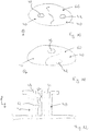
- Figs. 7, 8 and 9 show from a perspective, top and cross-sectional view respectively a two-component cartridge 1' that, unlike the cartridge 1 shown by figs. 1 and 3 , does not comprise a separate outlet 14. Instead, the head parts 6, 7 of the cartridge 1' each comprise an aperture 43 on which a respective connector 40 is to be arranged. For example, each connector 40 can be screwed separately onto the aperture 43 of the head part as shown by fig. 2 .
- the two connectors 40 When arranged at the apertures 43, the two connectors 40 form a snap fit connection with each other.
- the two connectors 40 can form for example an interference fit or a press fit or a bayonet type connection.
- the two connectors 40 are designed to snap into each other.
- the two connectors 40 can comprise complementary shapes, as shown for example by fig. 8 .
- the complementary shapes can intertwine respectively interlock together to form a combined connector.
- the combined connector can form a common dispensing outlet 60 for the two cartridge chambers 2, 3 that is provided by the two outlets 42 of the connectors 40.
- each connector 40 comprises a film 54 that extends over the entire radial surface of the aperture 43 of a respective cartridge chamber 2, 3.
- the outlets 42 of the two connectors 40 are therefore sealed against the medium contained by the cartridge chamber 2, 3.
- the film 54 is configured to burst in the region covering the outlet 42 on applying a dispensing pressure on the cartridge 1'.
- the connector 40 can comprise a film 54 with an aperture 56 in the region of the outlet 42 as shown by figs. 4b and 6b .
- a valve (not shown) can be arranged within the outlet 42 in order to regulate or direct a flow of the component or medium comprised by the cartridge chamber 2, 3.
- Figs. 10, 11 and 12 show further possible variants of the two connectors 40 forming a snap fit as the two connectors 40 shown in figs. 8 and 9 .
- the shapes of the two connectors 40 as shown here for example from a top view, can be any given as long as the two shapes are complimentary. The two shapes can therefore resemble two puzzle pieces.
- the two connectors 40 can comprise the same shape, with the two shapes engaging with each other. Moreover, the shapes engaging with each other can at least partially be formed along a radial surface of the connectors 40. As shown by fig.
- each connector 40 comprises a protrusion 62 respectively a snap-in nose, wherein the two protrusions 62 of the two connectors 40 are arranged such that the two protrusions 62 face each other when the two connectors 40 are arranged on the apertures 43 of the cartridge 1'.
- the two protrusions 62 are positioned on different heights along a longitudinal direction A of the connectors 40. In this way, the two protrusions 62 can engage with each other and hinder the two connectors 40 from disengaging when the two connectors 40 are installed on the apertures 43 of the head part 6, 7 of the cartridge 1'.
- one of the two connectors 40 can comprise a groove and the other connector 40 can comprise a protrusion designed to be received by the groove.
Landscapes
- Engineering & Computer Science (AREA)
- Mechanical Engineering (AREA)
- Coating Apparatus (AREA)
Priority Applications (4)
| Application Number | Priority Date | Filing Date | Title |
|---|---|---|---|
| EP20158124.6A EP3868685A1 (fr) | 2020-02-19 | 2020-02-19 | Cartouche et connecteur pour une cartouche |
| PCT/EP2020/067615 WO2021018484A1 (fr) | 2019-07-29 | 2020-06-24 | Cartouche et connecteur pour cartouche |
| EP20733650.4A EP3983310A1 (fr) | 2019-07-29 | 2020-06-24 | Cartouche et connecteur pour cartouche |
| US17/630,395 US20220315311A1 (en) | 2019-07-29 | 2020-06-24 | Cartridge and connector for a cartridge |
Applications Claiming Priority (1)
| Application Number | Priority Date | Filing Date | Title |
|---|---|---|---|
| EP20158124.6A EP3868685A1 (fr) | 2020-02-19 | 2020-02-19 | Cartouche et connecteur pour une cartouche |
Publications (1)
| Publication Number | Publication Date |
|---|---|
| EP3868685A1 true EP3868685A1 (fr) | 2021-08-25 |
Family
ID=69844346
Family Applications (1)
| Application Number | Title | Priority Date | Filing Date |
|---|---|---|---|
| EP20158124.6A Withdrawn EP3868685A1 (fr) | 2019-07-29 | 2020-02-19 | Cartouche et connecteur pour une cartouche |
Country Status (1)
| Country | Link |
|---|---|
| EP (1) | EP3868685A1 (fr) |
Citations (3)
| Publication number | Priority date | Publication date | Assignee | Title |
|---|---|---|---|---|
| WO2013056874A1 (fr) * | 2011-10-17 | 2013-04-25 | Sulzer Mixpac Ag | Cartouche et cartouche à plusieurs composants |
| WO2013078036A1 (fr) * | 2011-11-22 | 2013-05-30 | 3M Innovative Properties Company | Article et procédé de fermeture d'un récipient pliable |
| WO2016036620A1 (fr) * | 2014-09-01 | 2016-03-10 | Illinois Tool Works Inc. | Cartouche |
-
2020
- 2020-02-19 EP EP20158124.6A patent/EP3868685A1/fr not_active Withdrawn
Patent Citations (3)
| Publication number | Priority date | Publication date | Assignee | Title |
|---|---|---|---|---|
| WO2013056874A1 (fr) * | 2011-10-17 | 2013-04-25 | Sulzer Mixpac Ag | Cartouche et cartouche à plusieurs composants |
| WO2013078036A1 (fr) * | 2011-11-22 | 2013-05-30 | 3M Innovative Properties Company | Article et procédé de fermeture d'un récipient pliable |
| WO2016036620A1 (fr) * | 2014-09-01 | 2016-03-10 | Illinois Tool Works Inc. | Cartouche |
Similar Documents
| Publication | Publication Date | Title |
|---|---|---|
| US9555928B2 (en) | Cartridge and multicomponent cartridge | |
| US9901946B2 (en) | Cartridge and multicomponent cartridge | |
| US4988017A (en) | Dual chamber aerosol container | |
| EP1656309B1 (fr) | Capsule pour des materiaux a deux constituants | |
| US8899446B2 (en) | Apparatus for mixing and dispensing multiple flowable components | |
| US9975139B2 (en) | Cartridge and method for producing a cartridge | |
| US10105731B2 (en) | Cartridge, method of manufacturing same and multicomponent cartridge | |
| JP4236111B2 (ja) | 多室コンテナ・アセンブリ・システム | |
| US20220315311A1 (en) | Cartridge and connector for a cartridge | |
| CN114206158B (zh) | 用于混合和分配的容器系统 | |
| JP2011088675A (ja) | 緩衝要素を有する容器 | |
| US20240165656A1 (en) | Refillable mastic cartridge, dispenser, filling station and system comprising a mastic cartridge, a dispenser and a filling station, as well as cartridge and connector for a cartridge | |
| EP3868685A1 (fr) | Cartouche et connecteur pour une cartouche | |
| JP2011088672A (ja) | 一体化された閉止キャップを有するカートリッジ | |
| US20220379340A1 (en) | Cartridge for a dispensing device | |
| US20120248058A1 (en) | Cartridge having a plug | |
| US20210362938A1 (en) | Cartridge, dispensing assembly and method of manufacturing a cartridge | |
| KR102626019B1 (ko) | 산소혼합용기 | |
| WO2023161337A1 (fr) | Ensemble cartouche destiné à être inséré dans un distributeur et distributeur permettant de distribuer des matériaux | |
| KR20110046251A (ko) | 충격 흡수 요소를 구비한 용기 |
Legal Events
| Date | Code | Title | Description |
|---|---|---|---|
| PUAI | Public reference made under article 153(3) epc to a published international application that has entered the european phase |
Free format text: ORIGINAL CODE: 0009012 |
|
| STAA | Information on the status of an ep patent application or granted ep patent |
Free format text: STATUS: THE APPLICATION HAS BEEN PUBLISHED |
|
| AK | Designated contracting states |
Kind code of ref document: A1 Designated state(s): AL AT BE BG CH CY CZ DE DK EE ES FI FR GB GR HR HU IE IS IT LI LT LU LV MC MK MT NL NO PL PT RO RS SE SI SK SM TR |
|
| RAP3 | Party data changed (applicant data changed or rights of an application transferred) |
Owner name: MEDMIX SWITZERLAND AG |
|
| STAA | Information on the status of an ep patent application or granted ep patent |
Free format text: STATUS: THE APPLICATION IS DEEMED TO BE WITHDRAWN |
|
| 18D | Application deemed to be withdrawn |
Effective date: 20220226 |