EP3868663A1 - Passenger service unit with a cover, passenger seat area and vehicle with a passenger service unit - Google Patents
Passenger service unit with a cover, passenger seat area and vehicle with a passenger service unit Download PDFInfo
- Publication number
- EP3868663A1 EP3868663A1 EP21157433.0A EP21157433A EP3868663A1 EP 3868663 A1 EP3868663 A1 EP 3868663A1 EP 21157433 A EP21157433 A EP 21157433A EP 3868663 A1 EP3868663 A1 EP 3868663A1
- Authority
- EP
- European Patent Office
- Prior art keywords
- carrier element
- cover
- section
- service unit
- passenger
- Prior art date
- Legal status (The legal status is an assumption and is not a legal conclusion. Google has not performed a legal analysis and makes no representation as to the accuracy of the status listed.)
- Granted
Links
- 239000011248 coating agent Substances 0.000 claims abstract description 30
- 238000000576 coating method Methods 0.000 claims abstract description 30
- QVGXLLKOCUKJST-UHFFFAOYSA-N atomic oxygen Chemical compound [O] QVGXLLKOCUKJST-UHFFFAOYSA-N 0.000 claims description 20
- 229910052760 oxygen Inorganic materials 0.000 claims description 20
- 239000001301 oxygen Substances 0.000 claims description 20
- 239000004020 conductor Substances 0.000 claims description 16
- 238000009434 installation Methods 0.000 claims description 8
- 239000000835 fiber Substances 0.000 description 21
- 239000004744 fabric Substances 0.000 description 17
- 239000000463 material Substances 0.000 description 13
- 239000004033 plastic Substances 0.000 description 13
- 229920003023 plastic Polymers 0.000 description 13
- 239000004753 textile Substances 0.000 description 12
- 229920001296 polysiloxane Polymers 0.000 description 11
- 239000011888 foil Substances 0.000 description 4
- 230000010354 integration Effects 0.000 description 3
- 238000000034 method Methods 0.000 description 3
- 239000011149 active material Substances 0.000 description 2
- 230000000694 effects Effects 0.000 description 2
- 230000003287 optical effect Effects 0.000 description 2
- 238000009423 ventilation Methods 0.000 description 2
- 230000000007 visual effect Effects 0.000 description 2
- 239000011800 void material Substances 0.000 description 2
- 244000025254 Cannabis sativa Species 0.000 description 1
- 235000012766 Cannabis sativa ssp. sativa var. sativa Nutrition 0.000 description 1
- 235000012765 Cannabis sativa ssp. sativa var. spontanea Nutrition 0.000 description 1
- OKTJSMMVPCPJKN-UHFFFAOYSA-N Carbon Chemical compound [C] OKTJSMMVPCPJKN-UHFFFAOYSA-N 0.000 description 1
- 229920000742 Cotton Polymers 0.000 description 1
- 241000208202 Linaceae Species 0.000 description 1
- 235000004431 Linum usitatissimum Nutrition 0.000 description 1
- 238000013459 approach Methods 0.000 description 1
- 239000012237 artificial material Substances 0.000 description 1
- 235000009120 camo Nutrition 0.000 description 1
- 239000002775 capsule Substances 0.000 description 1
- 229910052799 carbon Inorganic materials 0.000 description 1
- 235000005607 chanvre indien Nutrition 0.000 description 1
- 238000004040 coloring Methods 0.000 description 1
- 238000010276 construction Methods 0.000 description 1
- 238000009792 diffusion process Methods 0.000 description 1
- 238000006073 displacement reaction Methods 0.000 description 1
- 230000005684 electric field Effects 0.000 description 1
- 239000011521 glass Substances 0.000 description 1
- 239000011487 hemp Substances 0.000 description 1
- 238000005286 illumination Methods 0.000 description 1
- 230000001771 impaired effect Effects 0.000 description 1
- 238000003780 insertion Methods 0.000 description 1
- 230000037431 insertion Effects 0.000 description 1
- 239000012528 membrane Substances 0.000 description 1
- 239000002184 metal Substances 0.000 description 1
- 239000000203 mixture Substances 0.000 description 1
- 239000005445 natural material Substances 0.000 description 1
- 239000006223 plastic coating Substances 0.000 description 1
- 238000004080 punching Methods 0.000 description 1
- 239000000779 smoke Substances 0.000 description 1
- 230000000391 smoking effect Effects 0.000 description 1
- 210000002268 wool Anatomy 0.000 description 1
Images


Classifications
-
- B—PERFORMING OPERATIONS; TRANSPORTING
- B64—AIRCRAFT; AVIATION; COSMONAUTICS
- B64D—EQUIPMENT FOR FITTING IN OR TO AIRCRAFT; FLIGHT SUITS; PARACHUTES; ARRANGEMENTS OR MOUNTING OF POWER PLANTS OR PROPULSION TRANSMISSIONS IN AIRCRAFT
- B64D11/00—Passenger or crew accommodation; Flight-deck installations not otherwise provided for
-
- B—PERFORMING OPERATIONS; TRANSPORTING
- B60—VEHICLES IN GENERAL
- B60Q—ARRANGEMENT OF SIGNALLING OR LIGHTING DEVICES, THE MOUNTING OR SUPPORTING THEREOF OR CIRCUITS THEREFOR, FOR VEHICLES IN GENERAL
- B60Q3/00—Arrangement of lighting devices for vehicle interiors; Lighting devices specially adapted for vehicle interiors
- B60Q3/40—Arrangement of lighting devices for vehicle interiors; Lighting devices specially adapted for vehicle interiors specially adapted for specific vehicle types
- B60Q3/41—Arrangement of lighting devices for vehicle interiors; Lighting devices specially adapted for vehicle interiors specially adapted for specific vehicle types for mass transit vehicles, e.g. buses
- B60Q3/47—Circuits; Control arrangements
-
- B—PERFORMING OPERATIONS; TRANSPORTING
- B64—AIRCRAFT; AVIATION; COSMONAUTICS
- B64D—EQUIPMENT FOR FITTING IN OR TO AIRCRAFT; FLIGHT SUITS; PARACHUTES; ARRANGEMENTS OR MOUNTING OF POWER PLANTS OR PROPULSION TRANSMISSIONS IN AIRCRAFT
- B64D11/00—Passenger or crew accommodation; Flight-deck installations not otherwise provided for
- B64D11/06—Arrangements of seats, or adaptations or details specially adapted for aircraft seats
- B64D11/0627—Seats combined with storage means
- B64D11/0629—Seats combined with storage means the storage means being specially adapted for emergency equipment
- B64D11/0632—Seats combined with storage means the storage means being specially adapted for emergency equipment for breathing apparatus
-
- B—PERFORMING OPERATIONS; TRANSPORTING
- B64—AIRCRAFT; AVIATION; COSMONAUTICS
- B64D—EQUIPMENT FOR FITTING IN OR TO AIRCRAFT; FLIGHT SUITS; PARACHUTES; ARRANGEMENTS OR MOUNTING OF POWER PLANTS OR PROPULSION TRANSMISSIONS IN AIRCRAFT
- B64D11/00—Passenger or crew accommodation; Flight-deck installations not otherwise provided for
- B64D11/06—Arrangements of seats, or adaptations or details specially adapted for aircraft seats
- B64D11/0647—Seats characterised by special upholstery or cushioning features
-
- B—PERFORMING OPERATIONS; TRANSPORTING
- B64—AIRCRAFT; AVIATION; COSMONAUTICS
- B64D—EQUIPMENT FOR FITTING IN OR TO AIRCRAFT; FLIGHT SUITS; PARACHUTES; ARRANGEMENTS OR MOUNTING OF POWER PLANTS OR PROPULSION TRANSMISSIONS IN AIRCRAFT
- B64D13/00—Arrangements or adaptations of air-treatment apparatus for aircraft crew or passengers, or freight space, or structural parts of the aircraft
-
- B—PERFORMING OPERATIONS; TRANSPORTING
- B60—VEHICLES IN GENERAL
- B60Q—ARRANGEMENT OF SIGNALLING OR LIGHTING DEVICES, THE MOUNTING OR SUPPORTING THEREOF OR CIRCUITS THEREFOR, FOR VEHICLES IN GENERAL
- B60Q3/00—Arrangement of lighting devices for vehicle interiors; Lighting devices specially adapted for vehicle interiors
- B60Q3/40—Arrangement of lighting devices for vehicle interiors; Lighting devices specially adapted for vehicle interiors specially adapted for specific vehicle types
- B60Q3/41—Arrangement of lighting devices for vehicle interiors; Lighting devices specially adapted for vehicle interiors specially adapted for specific vehicle types for mass transit vehicles, e.g. buses
- B60Q3/44—Spotlighting, e.g. reading lamps
-
- B—PERFORMING OPERATIONS; TRANSPORTING
- B60—VEHICLES IN GENERAL
- B60Q—ARRANGEMENT OF SIGNALLING OR LIGHTING DEVICES, THE MOUNTING OR SUPPORTING THEREOF OR CIRCUITS THEREFOR, FOR VEHICLES IN GENERAL
- B60Q3/00—Arrangement of lighting devices for vehicle interiors; Lighting devices specially adapted for vehicle interiors
- B60Q3/80—Circuits; Control arrangements
- B60Q3/82—Switches specially adapted for vehicle interior lighting, e.g. switching by tilting the lens
-
- B—PERFORMING OPERATIONS; TRANSPORTING
- B60—VEHICLES IN GENERAL
- B60R—VEHICLES, VEHICLE FITTINGS, OR VEHICLE PARTS, NOT OTHERWISE PROVIDED FOR
- B60R13/00—Elements for body-finishing, identifying, or decorating; Arrangements or adaptations for advertising purposes
- B60R13/02—Internal Trim mouldings ; Internal Ledges; Wall liners for passenger compartments; Roof liners
- B60R13/0212—Roof or head liners
-
- B—PERFORMING OPERATIONS; TRANSPORTING
- B64—AIRCRAFT; AVIATION; COSMONAUTICS
- B64D—EQUIPMENT FOR FITTING IN OR TO AIRCRAFT; FLIGHT SUITS; PARACHUTES; ARRANGEMENTS OR MOUNTING OF POWER PLANTS OR PROPULSION TRANSMISSIONS IN AIRCRAFT
- B64D11/00—Passenger or crew accommodation; Flight-deck installations not otherwise provided for
- B64D2011/0053—Cabin passenger reading lights
-
- B—PERFORMING OPERATIONS; TRANSPORTING
- B64—AIRCRAFT; AVIATION; COSMONAUTICS
- B64D—EQUIPMENT FOR FITTING IN OR TO AIRCRAFT; FLIGHT SUITS; PARACHUTES; ARRANGEMENTS OR MOUNTING OF POWER PLANTS OR PROPULSION TRANSMISSIONS IN AIRCRAFT
- B64D13/00—Arrangements or adaptations of air-treatment apparatus for aircraft crew or passengers, or freight space, or structural parts of the aircraft
- B64D2013/003—Cabin ventilation nozzles
-
- B—PERFORMING OPERATIONS; TRANSPORTING
- B64—AIRCRAFT; AVIATION; COSMONAUTICS
- B64D—EQUIPMENT FOR FITTING IN OR TO AIRCRAFT; FLIGHT SUITS; PARACHUTES; ARRANGEMENTS OR MOUNTING OF POWER PLANTS OR PROPULSION TRANSMISSIONS IN AIRCRAFT
- B64D2231/00—Emergency oxygen systems
-
- B—PERFORMING OPERATIONS; TRANSPORTING
- B64—AIRCRAFT; AVIATION; COSMONAUTICS
- B64D—EQUIPMENT FOR FITTING IN OR TO AIRCRAFT; FLIGHT SUITS; PARACHUTES; ARRANGEMENTS OR MOUNTING OF POWER PLANTS OR PROPULSION TRANSMISSIONS IN AIRCRAFT
- B64D2231/00—Emergency oxygen systems
- B64D2231/02—Supply or distribution systems
- B64D2231/025—Oxygen masks; Mask storages; Features related to mask deployment
Definitions
- the present invention relates to a passenger service unit with a carrier element that can be extended in a longitudinal direction and a cover in which at least one electrical and / or electronic element is integrated, as well as a passenger seating area and a vehicle with such a passenger service unit.
- the fabric has an integrated display device.
- the fabric may consist of or contain electrophoretic fibers to form a display device.
- a passenger seat is described that is covered with such a fabric in order to display information for the passengers.
- the invention is based on the object of providing a visually appealing interior device with additional functions for a vehicle.
- a passenger service unit for installation in a passenger seat area of a vehicle comprises a carrier element which can be extended in a longitudinal direction. Furthermore, the passenger service unit comprises a cover in which at least one electrical and / or electronic element is integrated. The coating can cover the carrier element at least in sections.
- a passenger service unit is also referred to as an individual / passenger service unit (PSU) and provides a passenger certain functions that he can control from the passenger seat.
- PSU can have outlet nozzles for fresh air, lamps for the individual passenger seats (in particular reading lamps), but also a call button to call service personnel.
- a PSU can also include oxygen masks that are ejected above the passenger seat in an emergency. Therefore, a PSU must be located in a certain position relative to the passenger seat (s).
- the carrier element which can be extended in a longitudinal direction, can have different dimensions in different directions.
- the dimensions of the carrier element can be changed in at least one of these directions, for example it can be extended or it can be shortened.
- the longitudinal direction is to be understood here as the direction in which the dimensions of the carrier element can be changed. This direction can coincide with a longitudinal direction of a vehicle (that is to say the direction of travel of the vehicle) in which such a passenger service unit can be installed, which is why the term longitudinal direction is used here in simplified form.
- the material of the cover can be a textile, a foil, silicone, rubber or other stretchable material / fabric.
- so-called “smart fabrics” or “smart clothes” can be used for the cover.
- the integration of the at least one electrical and / or electronic element into the cover takes place via a corresponding selection of a specific fabric, in particular so-called “smart fabrics” or “smart clothes” serve as a fabric for a textile cover.
- certain fibers can be selected to be used in the coating. These include, for example, electrically conductive fibers.
- electrophoretic fibers which are able to change their color at least in sections when an electric field is applied, or thermochromic fibers which change their color under the influence of temperature, can also be present in the one coating. Fibers with which a capacitive change can be recognized can also be used.
- a property of the fiber can change, which can be detected accordingly in a controller.
- Such fibers can be woven, knitted, braided or otherwise worked into the fabric of the cover.
- electrical and / or electronic components such as light-emitting diodes (LED), (separately designed) touch sensors and the like can also be integrated into the cover.
- sensors can also be integrated into the cover, the signals for controlling further electrical and / or can produce electronic components. For example, sensors for determining a temperature, a brightness (light), a humidity or the like can be integrated into the coating as electrical and / or electronic components.
- a personal fresh air nozzle can be activated / deactivated for the individual passenger if the temperature and / or humidity is above a predetermined threshold value, or a reading lamp for the individual passenger can be activated / deactivated if a brightness below a threshold is measured.
- these sensors can be integrated into fibers before the fabric for the cover is produced, and on the other hand, they can also be incorporated into the fabric afterwards.
- the (remaining) fibers of the coating can be made of any material.
- a fabric made from a natural material cotton, wool, flax, hemp, etc.
- Artificial materials can also be used, such as plastics that can be processed into fibers, silicone, glass (fibers), carbon, etc.
- a uniform carrier element can be used for the (entire) passenger service unit, while the cover can be adapted to the wishes of the vehicle operator or vehicle owner. So only the cover has to be adapted to the color wishes and other design options of the vehicle owner, for example by printing, coloring one or more fibers or layers of the cover, etc .. Furthermore, decorative elements can be attached to the cover, or by a corresponding color design in the Fabric or the material of the cover are incorporated.
- the integration of electrical and / or electronic elements in the cover allows a large number of functions to be offered to the passengers on the surface of the passenger service unit. As a result, a high-quality passenger service unit can be created at low cost. Furthermore, the functions of the Passenger service unit can be changed or adapted by simply replacing the cover, without having to install a completely new passenger service unit.
- the carrier element can be made of plastic or metal or a mixture or combination of both.
- the cover can form a pocket into which the carrier element is at least partially inserted, so that the cover is attached to the carrier element.
- the cover is double-layered on one side (or on one end), so that the cover can be arranged or rest on two sides of the carrier element. This enables the cover to be attached quickly to the carrier element, since only the carrier element has to be inserted into the pocket.
- the cover can be dimensioned such that a first section is the same size as a flat (front) side of the carrier element and a second section of the cover adjoining the first section is smaller than the flat side of the carrier element.
- the second section can thus be arranged on a (rear) side of the carrier element facing away from the flat side of the carrier element and encompass an edge of the carrier element lying therebetween.
- the cover can comprise further sections which span at least one further edge and / or are arranged at least on a further part of the (rear) side of the carrier element.
- the cover can also form a pocket on each of two opposite sides (be pocket-shaped), so that two opposite sides (ends) of the carrier element can each be inserted into a pocket. This allows the cover to be securely attached to the carrier element.
- Each pocket can be closed on at least one of its side sections, where the first and second (further) sections of the cover come to rest on one another. This makes it easy to apply the cover, a front side of the carrier element being completely covered by the cover.
- Each of the pockets can be provided with a rubber band that is located in particular in the section of the cover which is arranged on the rear side of the carrier element. This ensures the tension in the cover, which is located on the front side of the carrier element, and fixation of the carrier element in the pocket is improved.
- the Cover which is arranged on the back of the carrier element, be designed to be flexible, so that it applies the tension in the cover itself.
- the cover On the sides of the cover on which no pocket is arranged, the cover can be dimensioned such that it spans at least one edge of the carrier element.
- the carrier element can thus be completely covered by the cover on one (front) side.
- the cover is also formed with the overstretching of edges of the carrier element.
- a front side of the carrier element relates to a side facing a passenger area when the carrier element is installed in the passenger area (for example in a section of a vehicle).
- the front side of the carrier element is visible in the passenger area after installation.
- the rear side of the carrier element is correspondingly the side opposite the front side, which after installation in the passenger area is at least partially invisible or faces the primary structure of the vehicle.
- the carrier element can comprise a first section and a second section, the first section and the second section of the carrier element being coupled to one another.
- the first and second sections of the carrier element can be connected to one another and movable relative to one another.
- the carrier element can in particular have a flat basic shape, the second section being able to be moved relative to the first section within this area (plane) and / or out of this area. This allows at least one dimension of the carrier element to be changed.
- the movement can be a linear movement, a rotary movement, or a combination thereof (for example, moving along a curved path).
- the second section of the carrier element can be attached and fastened to the first section of the carrier element.
- the second section can comprise a protruding holding device which corresponds to a corresponding receptacle on the first section of the carrier element and can be fastened to / therein.
- a plurality of second sections can be attached and fastened to the first section in order to change the extension of the carrier element in the longitudinal direction.
- the respective change in the dimensions of the carrier element allows the carrier element and thus also the passenger service unit to be adapted when the passenger service unit is installed in a vehicle.
- the dimension can be changed in such a way that the carrier element is lengthened or shortened.
- a passenger service unit is installed along an associated service channel in the vehicle. Positioning along the service channel takes place taking into account the position of a passenger seat or a row of passenger seats below the service channel. If the distance between two subsequent passenger seats or rows of passenger seats is changed, a corresponding compensation can be made by changing the dimensions of the carrier element.
- the filling elements usually required for this, which represent a separate covering of the service channel, can thus be dispensed with. Since only the individual cover is visible instead of (as usual) a passenger service unit with additional filling elements, the ceiling area of the vehicle can be designed in a more visually appealing manner.
- the first section and the second section of the carrier element can be arranged in an overlapping manner. At least a part of the second section of the carrier element can overlap a corresponding part of the first section of the carrier element. This overlap can be present in particular when the second section rests against the first section of the carrier element or is at the smallest distance from the first section of the carrier element. If the second section is at a distance from the first section (greatest possible distance in the movement), the overlap can be minimal or completely eliminated. This enables the cover to always lie against a section of the carrier element. In other words, there is no void on the back of the cover that could otherwise be pressed into the void when touched. The cover could be damaged (for example punched through), which is prevented by the extended overlap area of the second section of the carrier element.
- the first section and the second section of the carrier element can be coupled to one another in a linearly movable manner via at least one rail.
- the at least one rail can be L-shaped, T-shaped, round, elliptical, etc., and can be brought into operative connection with a corresponding L-shaped, round, elliptical or similar rail.
- at least one holder can also be arranged, along which the rail of the other section of the carrier element can slide.
- the passenger service unit can furthermore comprise a locking device which fixes a relative position of the second section of the carrier element to the first section of the carrier element.
- the locking device is thus set up to block / lock the movement of the second section of the carrier element relative to its first section at any position.
- the locking can take place continuously and / or at positions with a predetermined grid.
- the predetermined grid can have distances that correspond to the distances between fastening positions in passenger seat rails. If, for example, passenger seats or rows of passenger seats arranged one behind the other are displaced by the fixed distance between the fastening positions in the seat rail, the dimensions of the carrier element and thus of the passenger service unit can be compensated more quickly.
- a stepless locking can take place, for example, by means of a screw or other clamping device that fixes the movable rail in any position.
- the cover can be designed to be stretchable, at least in sections.
- the cover can have stretchable fibers or other stretchable materials.
- the cover can be designed to be flexible in the section in which the second section can move from the first section of the carrier element, so that the cover does not impede the movement.
- the coating can comprise silicone / rubber-like material, so that it can be stretched at least in sections.
- the cover can also be dimensioned such that it can span the front side of the carrier element without substantial stretching when the second section of the carrier element is located furthest away from the first section of the carrier element. Furthermore, an opening can be provided between the first and second sections of the carrier element. If the second section is now moved to the first section of the carrier element (the carrier element becomes shorter overall), the excess coating can be passed through the Opening to be plugged into the back of the carrier element. For example, the cover can be clamped between the first and the second section of the carrier element, as a result of which the visual impression of the passenger service unit is not excessively impaired, since only the clamped fold can be seen.
- the cover is opaque. This also applies to a stretchable portion of the cover. At least the cover should remain opaque over an expansion area (maximum possible change in the dimension of the cover corresponding to the maximum possible change in the dimension of the carrier element).
- the fiber density of the fabric for the cover can be increased for this purpose.
- the cover can also consist of interconnected (for example glued) fibers, which are still stretchable at least in sections.
- the coating can also consist of a membrane or film in which the electrical and / or electronic elements are integrated.
- the cover can be arranged on an expandable plastic mold, the expandable plastic mold being shaped in such a way that it can be slipped over the carrier element.
- the plastic mold can be dimensioned in such a way that it engages around the front side of the carrier element and its edges and holds at least in sections on a rear side of the carrier element.
- the cover can be glued to the stretchable plastic mold or otherwise flatly attached to it.
- the cover can also be made of a stretchable material that performs the function of the stretchable plastic mold.
- a silicone mold that can be slipped over the carrier element is only mentioned as an example.
- a stretchable plastic mold can also be applied over the cover if the cover is already on the carrier element. If the plastic mold is designed to be transparent, additional protection of the cover and the electrical and / or electronic elements integrated therein can be ensured, while the cover can be easily and securely attached to the carrier element.
- the plastic mold can be made of silicone. This allows for a transparent, stretchable and durable plastic form both above and below the cover.
- the carrier element can comprise a fastening device which is arranged circumferentially at least in sections and to which a circumferential edge of the cover is fixed. Arranged circumferentially means in the edge region of the carrier element along a circumferential edge.
- the fastening device can be arranged on the edge or near the circumferential edge of the carrier element, for example on a rear side of the carrier element. The fastening device does not have to run continuously along the entire circumference of the carrier element, but only along sections thereof.
- the fastening device can be designed in the form of a groove into which the cover is clamped by means of a clamping cord.
- a clamping cord is made of a flexible material, for example, which is larger than the cavity formed by the groove, so that the clamping cord is clamped in the groove and thereby presses the coating against the inside of the groove.
- the groove can also be made of flexible material, into which a (fixed or flexible) clamping cord is inserted and thereby holds the cover in place.
- the fastening device can also comprise at least one magnet or a magnetically effective material, so that the coating can be held on the fastening device by means of magnetically effective material or a magnet.
- the fastening device can also comprise a section of a hook-and-loop tape comprising a barb, which is fastened to the rear side of the carrier element, the barbs being designed to hook into the cover. This enables the cover to be attached to the rear of the carrier element in a simple and inexpensive manner.
- the fastening device is arranged on a rear side of the carrier element.
- the coating is preferably dimensioned in such a way that it completely covers the front side of the carrier element and extends around the outer edge of the carrier element to at least the fastening device on the rear side of the carrier element.
- a cover that is tensioned all around the circumference avoids creases in the cover on the front side of the carrier element, which creates a high-quality appearance and yet enables a very quick and easy installation.
- the at least one electrical and / or electronic element can comprise a button, a lighting means and / or an illuminated or luminous symbol.
- the button can be provided with a switching function so that it functions, for example, as a call button or a switch for lighting. It is also possible that the button controls the volume of a loudspeaker or headphone output or the darkening of a window or the like. Two buttons can also be used in pairs for this purpose in order to manage the corresponding up and down control. Alternatively, the button can only close an electrical circuit as long as it is touched and / or pressed while a control takes over the actual switching process.
- buttons with the same function can also be provided in the cover.
- keys with the same function can be provided for each passenger to whom this passenger service unit belongs.
- the passenger service unit can belong to a row of seats with at least two seats. In the case of a call button in particular, this enables an exact assignment to the respective passenger, while conventional passenger service units usually only have one call button.
- the illuminant can function as general lighting of an area around the passenger service unit.
- a large number of lighting means can also be integrated in the cover or a large number of fibers can be stimulated to emit light.
- the cover and thus the passenger service unit can be illuminated in sections or completely.
- a color of the emitted light can also be set so that the area around the passenger service unit (in particular passenger seats arranged below the passenger service unit) can be illuminated.
- the lighting means can also be focused on a specific passenger seat and serve, for example, as a reading lamp. In the case of an arrangement of several passenger seats, several lighting means can of course be provided so that a reading lamp is assigned to each passenger seat.
- the symbol can be arranged in the cover in a self-luminous manner (symbol made up of self-luminous areas or fibers of the cover), and it can also be combined with a light source (the light source serves as background lighting for a symbol provided in the cover).
- the symbols can be, for example, instructions to the passengers, the lighting of which can be controlled centrally. For example, it can be symbols act like "do not smoke”, “do not use mobile devices", “fasten your seatbelts", etc.
- a button can also be combined with a symbol and / or a lamp.
- a symbol in the cover can light up independently or be illuminated by a lamp to confirm the switching process, and when the button is pressed again, the symbol's illumination can go out again.
- the carrier element can comprise a section that is pivotable with respect to the rest of the carrier element, a position of the pivotable section coinciding with a position of one of the at least one electrical and / or electronic element.
- the pivotable section is arranged on a rear side of the electrical and / or electronic element when the cover is arranged and fastened on the carrier element.
- the pivotable section can relate to an edge section of the carrier element on which symbols are provided in the cover.
- the symbols can be brought into a more visible position.
- the centrally controlled symbols described above can be arranged on a pivotable section of the carrier element which can be folded out of a general ceiling surface of the passenger seating area into the passenger seating area.
- the symbols are not on the ceiling of the passenger seating area, but instead assume a position in which they can be better seen by a passenger.
- the unfolding can be done manually or controlled by a machine. For example, in an aircraft during take-off and landing, symbols that indicate that it is mandatory to wear seat belts and the like can be moved into the field of vision of the passengers.
- the cover is flexible and can therefore follow the movement of the pivotable section of the carrier element. An otherwise necessary and complex cable routing is omitted, since an electrical supply is present in the cover.
- the pivotable section is arranged in a central region of the carrier element, that is to say that the otherwise flat carrier element is present around the pivotable section. This allows the pivotable section, deviating from the surface formed by the rest of the carrier element, assume a different orientation.
- the pivotable section can assume a round shape, an elliptical shape, a rectangular shape or any arbitrary polygonal shape.
- the pivotable section of the carrier element can be equipped on a side facing the cover with a part of a hook-and-loop tape comprising a barb, the barbs being designed to hook into the cover.
- the cover can be effectively fixed to the pivotable section in a simple manner, merely by arranging the Velcro strip on the pivotable section.
- the cover is thus carried along in the area of the pivotable section with every movement of the pivotable section. If there is an electrical and / or electronic element in this area of the coating, its orientation can easily be changed. For example, a light source, and in particular its light cone, can be easily aligned by means of the pivotable section.
- the pivotable section of the carrier element can be provided with a magnet or a magnetically active material on a side facing the cover, a magnetically active material or a magnet being integrated in the cover at a corresponding position. This also enables the cover to be fastened to the pivotable section in a manner that is quick to set up.
- the pivotable section in the form of a ball joint can be provided in / on the carrier element merely as an example.
- a holder in the form of a capsule into which a spherical component is inserted can be provided on the carrier element.
- the latter On the side of the spherical component facing the cover, the latter can have a flattened area to which the cover is attached.
- the flat area can be arranged such that the pivotable section can be brought into a position so that the flat area and the area of the carrier element arranged around it form a continuous common plane.
- an electrically conductive conductor track (electrical line) can be integrated in the coating, which is electrically connected to the at least one electrical and / or electronic element.
- This enables a non-visible electrical connection of the electrical and / or electronic element.
- the individual electrical connection of the electrical and / or electronic element when installing the passenger service unit is omitted, since both the conductor track and the electrical and / or electronic element are integrated in the cover.
- different conductor tracks or conductor tracks can be arranged in different layers in the coating.
- conductor tracks of a layer can be assigned a specific function.
- the conductor tracks for supplying power to lighting elements can be arranged in a first layer, while conductor tracks for connecting switching elements (buttons) are arranged in another layer.
- the coating can comprise a contact arrangement with a multiplicity of contacts for connecting the electrically conductive conductor track (s).
- the coating can contain a multiplicity of electrical and / or electronic elements as well as an (associated) multiplicity of conductor tracks, all of which are connected to the contact arrangement of the coating.
- the carrier element can comprise a contact arrangement with a multiplicity of contacts which are designed to produce electrical connections with the multiplicity of contacts of the contact arrangement of the cover by making mutual contact.
- the two contact arrangements of the carrier element and the cover thus form an electrical connection between the carrier element and the cover.
- Both contact arrangements can be designed as a plug connection.
- contact arrangements in which the respective multiplicity of contacts merely touch one another without being plugged into one another are easier to connect.
- the respective multiplicity of contacts in each of the contact arrangements can be arranged essentially in one plane. If necessary, the contacts can easily lift off a housing of the contact arrangement or protrude from the housing. As a result, the large number of contacts of the two contact arrangements can easily be placed on top of one another and establish reliable electrical contact.
- the contact arrangement of the carrier element can be connected to a controller which conducts electrical signals to the plurality of contacts of the contact arrangement in order to control the at least one electrical and / or electronic element in the coating.
- the control can be arranged on the carrier element, for example on a rear side of the carrier element.
- control can also be provided centrally at another point in the vehicle and be connected to the contact arrangement of the carrier element via electrical lines.
- the control can be part of a passenger cabin management system, for example, if some of the electrical and / or electronic elements have to be controlled centrally (in the case of illuminated symbols), or signals from some of the electrical and / or electronic elements have to be routed to a central point (for example call button ).
- the controller can also merely represent a power supply that applies a voltage to the at least one electrical and / or electronic element (via the contact arrangements and electrical lines).
- the control in particular when arranged on the carrier element, can comprise an electrical and / or electronic component that controls the electrical and / or electronic element in the cover. For example, when a button / switch in the cover is actuated, another electrical and / or electronic element in the cover can be controlled, such as switching a light on and off.
- control can also be integrated into the cover.
- circuits can be made very thin and thus integrated into the coating.
- the contact arrangement of the cover can only serve as a power supply for the cover and its circuits / controls.
- the contact arrangement of the carrier element can comprise a holding device and / or the contact arrangement of the cover can comprise a holding device.
- the respective holding device is set up to hold the other contact arrangement.
- a magnet or a plurality of magnets can be arranged in a contact arrangement, which magnet can come into operative connection with a magnetically active component (or likewise a magnet) at the corresponding position of the other contact arrangement.
- the passenger service unit can furthermore comprise an oxygen mask storage device which is set up to accommodate oxygen masks and, in an emergency, to release an opening for access to the oxygen masks.
- Oxygen mask storage is for example arranged on a rear side of the carrier element and the opening extends through the carrier element from its rear side to its front side.
- the opening can be closed with a flap that can be opened in an emergency.
- the opening of the flap can be controlled centrally, with the flap being pretensioned, for example, and opening automatically after a lock has been released.
- the cover can have a perforation (for example a microperforation), the position of which corresponds to the opening of the oxygen mask storage device or its flap.
- the perforation can be set up to enable an opening in the cover corresponding to the opening of the oxygen mask storage.
- the perforation can be designed to tear open when the flap opens.
- the flap can also be provided with a hook-and-loop tape comprising barb, so that when the flap is opened, the section of the cover attached to the barbs moves with the flap.
- an optically hidden oxygen mask storage through the cover) can be provided which, in an emergency, provides oxygen masks for passengers as usual.
- the passenger service unit can comprise an opening for a fresh air supply.
- the carrier element can include an opening and the cover can also include an opening at a location corresponding to the opening in the carrier element.
- a conventional fresh air supply in particular a fresh air nozzle that can be adjusted by a passenger, can be installed on the carrier element.
- the opening in the carrier element can also be used for the arrangement of a loudspeaker.
- a separate opening can be provided in the support element for a loudspeaker. Since the sound of the loudspeaker can penetrate through the textile cover, an opening in the textile cover at a corresponding position is not necessary. In the case of an impermeable (rubber or film-like cover), however, such an opening must be provided as an alternative.
- a passenger seating area for a vehicle comprises at least one passenger service unit according to the first aspect or one of its implementation variants.
- the at least one passenger service unit can be arranged in a ceiling area of the passenger seat area above at least one passenger seat.
- the at least one passenger service unit can be arranged in a ceiling area of the passenger seating area, which an average passenger can reach with his hands while sitting.
- a service channel which is part of a ceiling construction above the passenger seat area, can be arranged above the passenger seat area.
- Lines for supplying the individual passenger service units can be arranged in the service channel, for example power lines, fresh air lines, oxygen lines, etc.
- the service channel can comprise an installation rail or other holder, while a passenger service unit is equipped with a corresponding component which can be brought into engagement with the installation rail or holder and thereby holds the passenger service unit in the service channel.
- a simple clamping device can be arranged in the service channel, into which a corresponding holding element of the passenger service unit can be clamped. A click mount for the passenger service unit can thereby be achieved.
- the carrier element of the at least one passenger service unit can comprise a curved section, the curved section extending from the ceiling area of the passenger seat area in the direction of the passenger seat.
- the curved section can be seen more easily by passengers seated or standing in the passenger seating area, since it is at a better angle to the line of sight of the passengers (compared to a continuous plane forming the ceiling).
- a multiplicity of carrier elements with a passenger service unit can be installed in the service channel.
- a single cover can span the multitude of carrier elements. This not only enables a uniform, continuous image, which enables a visually appealing ceiling design for the vehicle.
- several passenger service units can also be installed quickly with the necessary functionality that is integrated in the cover.
- a vehicle can comprise at least one passenger service unit according to the first aspect and / or at least one passenger seating area according to the further aspect.
- the vehicle can be any means of transport, especially means of mass transportation.
- the vehicle can be an airplane, a train, a bus, a ship or the like.
- the at least one passenger service unit can also be installed in a car or driver's cab of a truck.
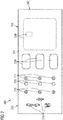
- a passenger service unit 10 which comprises a carrier element 100 and a cover 200.
- the carrier element 100 has, in particular, a flat and thin first section 101, which extends essentially in a plane that forms a ceiling section of a passenger seat area 2 ( Figure 17 ) forms, or is aligned parallel to it.
- the first section 101 can also assume other shapes, with a front face that is as flat as possible (the one shown in FIG Figure 3 facing side or in Figure 1 non-visible side) forms a visually appealing surface for the cover 200.
- Holding devices 110 for example for holding lighting elements, as well as openings 120, for example passage openings for fresh air, and / or ventilation grilles and / or loudspeakers can be provided on the rear side of the carrier element 100.
- an oxygen mask storage 130 can be provided in which oxygen masks are stored. This is particularly important in the case of passenger service units 10 in aircraft 1 ( Figure 17 ) intended.
- the carrier element 100 can furthermore comprise a second section 102, which is connected to the first section 101 and is movable relative thereto. As a result, the length of the carrier element 100 can be made variable.
- a further section 104 can be provided, which can be formed as part of the second section 102 and, when the second section 102 is moved, overlaps to different degrees with the first section 101, which in relation to FIG Figures 10 and 11 will be described in more detail.
- the carrier element 100 can comprise a third section 103 which protrudes in a curved manner from the first section 101.
- the third section 103 has an angle to the plane formed by the first section 101. This enables better visibility of the third section 103, as shown in FIG Figure 3 is shown.
- brackets 105 can be arranged on the rear side of the carrier element 100. These brackets 105 are used to fasten the carrier element 100 and thus the passenger service unit 10 in a vehicle 1. Cylindrical brackets 105 are shown only by way of example, which can be inserted into corresponding clamping devices in the vehicle, whereby the passenger service unit 10 is held.
- the cover 200 forms the visible surface of the passenger service unit 10 on the front side of the carrier element 100.
- the cover 200 has, corresponding to the carrier element 100, a first section 201, a second section 202 and a third section 203, which essentially correspond to the dimensions of the corresponding sections 101 to 103 of the carrier element 100 correspond.
- the cover 200 can have a flexible area 204 in which the cover 200 is stretchable.
- the entire cover 200 can be designed to be stretchable.
- At least one electrical and / or electronic element 210 to 216 is integrated in the cover 200.
- lighting means 210 and associated on and off switches 211 can be integrated in the cover 200.
- So-called “smart fabrics” are particularly suitable for this, in which electrically conductive tracks / fibers and / or electrical / electronic components are integrated.
- the latter also include call buttons 215, which can optionally have a light source in order to display a switching state of the call button 215.
- luminous symbols 216 can also be integrated in the cover 200.
- the arrangement of the electrical / electronic elements 210 to 216 as well as other portions of the cover 200 is not limited to the particular arrangement shown.
- the arrangement of the buttons / switches 211 in the examples is shown in FIG Figures 2 and 3 different. That’s what in Figure 3 Optical elements, such as lenses (disks), diffusion disks, or the like to be recognized, which can be arranged in front of corresponding illuminants.
- Openings 220 can be seen in the textile cover 200 for the fresh air supply or loudspeakers, while in FIG Figure 3 there are no such openings.
- the textile cover 200 can be air-permeable (for example perforated) so that a closed textile surface is formed, although fresh air can be supplied to each individual passenger and sound can also be transmitted through the textile cover 200.
- air-permeable for example perforated
- openings must be provided for both the air and the sound.
- a perforation is provided in the cover 200 which defines an opening area 230 for the oxygen mask storage 130.
- This perforation can tear if, for example, a flap or similar closure of the oxygen mask storage 130 opens (in Figure 1 downward).
- the passenger service unit 10 can be produced by slipping the cover 200 over certain sections of the carrier element 100. As in particular in Figure 3 can be seen, a very thin (slim) passenger service unit 10 can be created in a simple manner.
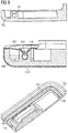
- FIG 4 the back of the cover 200 is shown schematically.
- a pocket 250 is formed at each end of the cover 200. This can be done, for example, by folding over the ends 251 of the cover 200 on its rear side.
- the ends 251 in the side area (in Figure 4 top and bottom) are connected to the main portion 201 of the cover 200. Of course, the entire side areas can be closed. This creates pocket openings across the width of the cover 200, into which the ends (second section 102 and third section 103) of the carrier element 100 can be inserted.
- the cover 200 is thus placed on the carrier element 100 like a sock.
- a contact arrangement 260 having a plurality of contacts 262 may be located on the rear side of the cover 200.
- the contacts 262 are used to connect electrically conductive conductor tracks 263 which are integrated in the coating 200.
- the electrical / electronic elements 210 to 216 can be electrically connected to the contacts 262 of the contact arrangement 260 through the conductor tracks 263.
- the conductor tracks 263 can be integrated in the covering 200 in that they are arranged in its fibers or form parts of the fibers of the covering 200.
- the contact arrangement 260 may further comprise a holding device 261 which, with regard to Figure 16 will be explained in more detail.
- the carrier element 100 can be threaded with one end at one end 203 of the cover 200, and then be threaded at an opposite end 202 of the cover 200.
- the cover 200 spans the carrier element 100.
- the carrier element 100 is inserted in order to hold the cover 200.
- the cover 200 can be held on the carrier element 100 with a silicone cover (not shown separately). It is also possible for the silicone cover to touch the carrier element 100 while the cover 200, for example made of fabric or textile, is arranged (for example glued) on the silicone cover. In this case, the ends 202, 203 of the cover 200 do not have to be pocket-shaped. Instead, a small overlap area is sufficient, as shown in Figure 5 is shown.
- the silicone cover can be stiffer than a thinner cover 200, for example a textile cover, and therefore achieve a greater clamping effect on the carrier element 100.
- a flexible section 204 of the textile cover 200 and / or the silicone cover facilitates the application of the cover 200 to the carrier element 100.
- a further section 205 of the cover 200 can be pushed into an opening between the second section 102 and the first section 101 of the carrier element 100 and clamped there (see FIG Figure 6 ).
- the section of the carrier element 100 shown on the left can also be a carrier element 100 of an adjacently arranged passenger service unit 10, while the cover 200 is stretched over several carrier elements 100 of several passenger service units 10. Any excess material 205 of the coating 200 can be between two carrier elements 100 are inserted and clamped, as shown in FIG Figure 6 can be seen.
- the carrier element 100 can have an inclined section 103 which, as in FIG Figure 6 is aligned with a rear side of the carrier element 100 or, as in FIG Figure 7 shown, is aligned with a front side of the carrier element 100. In both cases, an inclined side is created which can be seen better by a passenger below the passenger service unit 10.
- This inclined section 103 is particularly suitable for the arrangement of symbols 216 which indicate certain information to the passenger, such as a smoking ban, wearing seat belts, prohibiting the use of electronic devices, etc.
- the carrier element 100 can also be designed to be consistently flat, as shown in FIG Figure 8 is shown. This shape is particularly suitable if no parts of the ceiling section of the passenger seat area 2 are to protrude into the latter. As in the Figures 5 to 8 As can be seen, the overlapping areas 250, which form a pocket, can have different thicknesses. It is therefore advisable, in the area of an inclined section 103 of the carrier element 100 ( Figure 7 ) or in the case of a stretchable portion 204 of the cover 200 ( Figure 8 ) to provide a deeper pocket 250 in order to ensure a better hold of the cover 200.
- a fastening device 140 can be provided for fastening the cover 200 to the carrier element 100.
- the carrier element 100 can have a fastening device 140 which is arranged circumferentially at least in sections and which is provided in particular on a rear side of the carrier element 100.
- a simple form of the fastening device 140 can be a barbed section of a Velcro strip, wherein the barbs can hook onto the cover 200.
- FIG Figure 9 A fastening device 140 that is more frequently reusable and more flexible in the longitudinal direction of the carrier element 100 is shown in FIG Figure 9 shown.
- This is designed in the form of a groove on the rear side of the carrier element 100, into which a clamping cord 141 or a similar elongated clamping element can be inserted.
- the clamping cord 141 fits into a part of the groove 140 from which it can only be released by flexible deformation.
- One end of the cover 200 can be pinched between the clamping cord 141 and the groove 140.
- the cross section of the groove 140 can taper towards an opening, so that the clamping cord 141 has an even better hold or the clamping cord 141 is prevented from slipping out.
- the brackets 105 on the rear side of the carrier element 100 are fastened in a vehicle 1 with a corresponding clamping device (not shown).
- the mountings 105 have a similar shape to the clamping cord 141, but are attached to the rear side of the carrier element 100 or integrated therein.
- a clamping device is therefore provided on the vehicle 1, which corresponds to the fastening device 140, so that the clamping device in the vehicle 1 and the holder 105 are inserted into one another and held by means of a clamping effect.
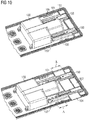
- the second section 102 of the carrier element 100 is shown in more detail.
- the second section 102 rests against the first section 101 of the carrier element 100 (has the smallest distance from the first section 101).
- the second section 102 is shown spaced apart from the first section 101 of the carrier element 100.
- a rail 154 can be provided, which is shown in FIG Figure 11 is shown in detail.
- the rail 154 may be attached to and extend away from the second portion 102.
- the rail 154 can be brought into engagement with a corresponding elongate element 151 so that the rail 154 can only move in the longitudinal direction of the rail 154.
- a locking device 150 can fix a relative position of the second section 102 to the first section 101 of the carrier element 100.
- the illustrated variant of the locking device 150 is provided with openings 152 in the elongated element 151 on the first section 101 in a predetermined grid.
- a corresponding locking element 153 here in the form of a tab, can dip into one of the openings 152, as a result of which movement of the rail 154 relative to the elongate element 151 is blocked.
- the tab 153 can, for example, be pretensioned and automatically move into the opening 152 when it reaches an opening 152. To release the tab 153 must be pulled out of the opening 152, whereby the second section 102 of the carrier element 100 can be moved again.
- the predetermined grid can correspond to a grid with which rows of seats can be arranged in the vehicle 1.
- seat rails have a corresponding grid. If the grids of the seat rail and the openings 152 match, it is possible to increase the seat spacing between two rows of seats also extend the length of the passenger service unit 10 by the same amount. As a result, a service channel in which the passenger service unit 10 is arranged can be closed without additional cover panels.
- Figure 12 shows an alternative embodiment of a rail 154.
- the rail 154 of the second section 102 has a rectangular cross section, which is inserted into a corresponding rectangular holding element 151.
- a screw 155 which clamps the rail 154 in place, can be provided on this holding element 151.
- Figure 12 finally also shows openings 120 in the carrier element 100, in which fresh air nozzles or outlets of fresh air lines and / or loudspeakers can be arranged.
- the second section 102 of the carrier element 100 can also be removed completely, as a result of which one dimension of the carrier element 100 can be shortened. As soon as the rail 154 is no longer in engagement with the elongate (holding) element 151, the second section 102 can be removed.
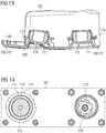
- the Figures 13 and 14 represent details of a pivotable section 111 of the carrier element 100.
- a holding device 110 in the form of a receptacle can be provided on the rear side of the carrier element 100.
- a pivotable section 111 of the carrier element 100 is inserted into the holding device 110, the pivotable section 111 being able to rotate at least partially in the holding device 110.
- the holding device 110 and the pivotable section 111 can have corresponding spherical surfaces.
- the holding device 110 can comprise a magnet (not shown) in order to hold the pivotable section 111 in the holding device 110.
- the holding device 110 can be dimensioned large enough so that the pivotable section 111 cannot slip out.
- the holding device 110 and the pivotable section 111 can be provided at a position of the carrier element 100 which corresponds to or corresponds to a position of one of the at least one electrical and / or electronic element 210 to 216 in the cover 200.
- a part of a Velcro strip 112 comprising a barb is provided on a side of the pivotable section 111 facing the cover 200.
- the barbs of the Velcro tape 112 are designed to hook into the cover 200.
- a part of a Velcro strip (not shown separately) which includes loops and which engages with the barbs 112 can also be provided on the cover 200. This allows the coating 200, as in Figure 13 align by pivoting the pivotable portion 111.
- the electrical / electronic element 210 to 216 provided at this position can therefore also be aligned by the pivotable section 111.
- a light source 210 for example in the form of a flat LED, can be integrated in the cover 200 (as shown in FIG Figure 13 shown) and abut against the pivotable section 111 via the barbs 112. This enables the lighting means (in particular the lighting cone) to be aligned with the aid of the pivotable section 111.
- a lighting means 275 can be arranged in the pivotable section 111.
- the light of the illuminant 275 can exit through an opening 113 in the pivotable section 111. If the cover 200 is now designed to be translucent (transparent and / or perforated and / or by means of an opening) at the position of the pivotable section 111, a pivotable lamp can be implemented in a simple and visually appealing manner.
- a further part of a Velcro strip 115 comprising barb can be arranged around the pivotable section 111 on the carrier element 100. This avoids stresses due to a larger area of the cover 200 when the pivotable section 111 is moved.
- the cover 200 can comprise punched-out portions which form two hook-shaped sections 271, 272. Electrical contact surfaces 273 can be provided at the respective ends of the hook-shaped sections 271, 272. Furthermore, electrical lines (conductor tracks) can be provided in the sections 271, 272 and the adjoining areas of the coating 200. An electrical connection is thereby integrated in the cover 200.
- the electrical contact surfaces 273 can be connected to an electrical / electronic component which is located outside the cover 200.
- a light source 275 as shown in FIG Figure 14 right and in Figure 15 is shown below in a sectional view, with the electrical contact surfaces 273 of the sections 271, 272 are electrically connected (the sections 271, 272 are for better clarity of the Figure 15 only provided with reference symbols for one of the illuminants 275).
- the lighting means 275 can thus comprise a foot 276 which is fastened, for example, in the pivotable section 111 of the carrier element 100 and has corresponding electrical connections to which the contact surfaces 273 can be attached. This variant enables even larger electrical / electronic components to be connected.
- the opening in the cover 200 resulting from the punching can be closed by an optical element 212.
- Figure 16 shows schematically an electrical and / or electronic control 170.
- This can for example be arranged and fastened on the rear side of the carrier element 100.
- the controller 170 can be arranged anywhere on the vehicle.
- the controller 170 can also be at least partially integrated in the cover 200.
- the controller 170 is used to supply the electrical and / or electronic elements 210 to 216 in the cover 200 with electrical current and / or electrical signals.
- the controller 170 has a contact arrangement 160.
- the contact arrangement 160 can be provided with a multiplicity of contacts 162.
- the arrangement of the contacts 162 corresponds to the arrangement of the contacts 262 of the contact arrangement 260 of the coating 200 (see FIG Figure 4 ).
- the contact arrangement 160 also has a holding device 161 which, in its position relative to the contacts 162, corresponds to the holding device 261 on the cover 200, likewise relative to its contacts 262.
- the holding devices 161, 261 can be at least one magnet, so that the two contact arrangements 160, 260 can easily be brought together and firmly connected to one another, with the individual contacts 162, 262 coming to rest on and against one another at the same time, an electrical one Establish connection.
- This form of electrical connection enables a quick connection Installation of the cover 200 and, at the same time, rapid electrical connection via the contact arrangements 160, 260.
- an area for the contact arrangement 160 on the carrier element 100 is shown schematically.
- an opening can be provided in the carrier element 100, through which the contact arrangement 160 extends so that the contact arrangement 260 of the coating 200 can reach and contact it.
- the contact arrangement 160 is integrated into the carrier element 100 and a connection option for connecting the controller 170 is provided on the rear side of the carrier element 100.
- the controller 170 is not arranged and fastened to the carrier element 100, only one connection option needs to be provided for the contact arrangement 160 of the carrier element 100.
- FIG. 3 shows a schematic representation of a vehicle 1, here an aircraft, with a passenger seat area 2. At least one passenger seat 5 and an associated passenger service unit 10 are installed in the passenger seat area 2.
- a plurality of seats / rows of seats 5 can be provided one behind the other in the vehicle 1, with a corresponding plurality of passenger service units 10 being arranged above each seat / row of seats 5. It is sufficient if a corresponding plurality of carrier elements 100 is arranged above each seat / row of seats 5 and a single one cover 200 spans at least two of the plurality of carrier elements 100. As a result, a uniform visual impression can be achieved in the passenger seating area 2. It is also possible to provide a single contact arrangement 260 of one cover 200 (and correspondingly a single contact arrangement 160 in / on the carrier element 100), via which all electrical / electronic elements 210 to 216 can be electrically connected to a controller 170.
- a central controller 7 is also shown by way of example, via which the at least one electrical / electronic element 210 to 216 can be controlled.
- the one cover 200 is electrically connected to the central control 7.
- it can be a cabin management system 7 with which individual or all of the electrical / electronic elements 210 to 216 can be controlled.
- the central controller 7 can be provided in the cabin or, alternatively, in a cockpit of the vehicle 1.
- the central controller 7 can also be connected to a controller 170 in / on the carrier element 100 and / or a controller 170 in the cover 200 and interact with it to control the at least one electrical / electronic element 210 to 216.
Abstract
Es wird eine Passagierserviceeinheit, ein Passagiersitzbereich sowie ein Fahrzeug jeweils mit einer Passagierserviceeinheit beschrieben, wobei die Passagierserviceeinheit aus einem in einer Längsrichtung verlängerbares Trägerelement und einem Überzug besteht. Der Überzug bedeckt das Trägerelement zumindest abschnittsweise. In dem Überzug ist mindestens ein elektrisches und/oder elektronisches Element integriert.A passenger service unit, a passenger seating area and a vehicle each with a passenger service unit are described, the passenger service unit consisting of a carrier element that can be extended in a longitudinal direction and a cover. The coating covers the carrier element at least in sections. At least one electrical and / or electronic element is integrated in the cover.
Description
Die vorliegende Erfindung betrifft eine Passagierserviceeinheit mit einem in einer Längsrichtung verlängerbaren Trägerelement und einem Überzug, in den mindestens ein elektrisches und/oder elektronisches Element integriert ist sowie einen Passagiersitzbereich und ein Fahrzeug mit solch einer Passagierserviceeinheit.The present invention relates to a passenger service unit with a carrier element that can be extended in a longitudinal direction and a cover in which at least one electrical and / or electronic element is integrated, as well as a passenger seating area and a vehicle with such a passenger service unit.
In Verkehrsmitteln, insbesondere in Flugzeugen, Bussen oder Zügen, werden sichtbare Oberflächen der Inneneinrichtung gerne mit Textilien oder Folien bespannt, da dies optisch ansprechende (und somit hochwertiger wirkende) Oberflächen im Vergleich zu herkömmlichen Kunststoffoberflächen ermöglicht.In means of transport, especially in airplanes, buses or trains, visible surfaces of the interior fittings are often covered with textiles or foils, as this enables optically appealing (and thus high-quality-looking) surfaces compared to conventional plastic surfaces.
In der
Der Erfindung liegt die Aufgabe zugrunde, eine optisch ansprechende Inneneinrichtung mit zusätzlichen Funktionen für ein Fahrzeug bereitzustellen.The invention is based on the object of providing a visually appealing interior device with additional functions for a vehicle.
Diese Aufgabe wird durch eine Passagierserviceeinheit mit den Merkmalen gemäß Anspruch 1, einen Passagiersitzbereich mit den Merkmalen gemäß Anspruch 13 und ein Fahrzeug mit den Merkmalen gemäß Anspruch 15 gelöst.This object is achieved by a passenger service unit with the features according to
Gemäß einem ersten Aspekt zum besseren Verständnis der vorliegenden Offenbarung umfasst eine Passagierserviceeinheit zum Einbau in einem Passagiersitzbereich eines Fahrzeugs ein in einer Längsrichtung verlängerbares Trägerelement. Ferner umfasst die Passagierserviceeinheit einen Überzug, in den mindestens ein elektrisches und/oder elektronisches Element integriert ist. Dabei kann der Überzug zumindest abschnittsweise das Trägerelement bedecken.According to a first aspect for a better understanding of the present disclosure, a passenger service unit for installation in a passenger seat area of a vehicle comprises a carrier element which can be extended in a longitudinal direction. Furthermore, the passenger service unit comprises a cover in which at least one electrical and / or electronic element is integrated. The coating can cover the carrier element at least in sections.
Eine Passagierserviceeinheit wird auch als individuelle/persönliche Serviceeinheit (personal/passenger service unit - PSU) bezeichnet und bietet einem Passagier bestimmte Funktionen, die er von dem Passagiersitz aus steuern kann. Beispielsweise kann eine PSU Auslassdüsen für Frischluft, Lampen für die einzelnen Passagiersitze (insbesondere Leselampen), aber auch eine Ruftaste, um Servicepersonal zu rufen, aufweisen. In Flugzeugen kann eine PSU auch Sauerstoffmasken, die im Notfall oberhalb des Passagiersitzes ausgeworfen werden, umfassen. Daher muss eine PSU an einer bestimmten Position relativ zu dem/den Passagiersitz(en) angeordnet sein.A passenger service unit is also referred to as an individual / passenger service unit (PSU) and provides a passenger certain functions that he can control from the passenger seat. For example, a PSU can have outlet nozzles for fresh air, lamps for the individual passenger seats (in particular reading lamps), but also a call button to call service personnel. In aircraft, a PSU can also include oxygen masks that are ejected above the passenger seat in an emergency. Therefore, a PSU must be located in a certain position relative to the passenger seat (s).
Das in einer Längsrichtung verlängerbare Trägerelement kann unterschiedliche Dimensionen in verschiedenen Richtungen aufweisen. In mindestens einer dieser Richtungen ist das Trägerelement in seiner Dimension veränderbar, beispielsweise verlängerbar oder es kann verkürzt werden. Unter Längsrichtung ist hier die Richtung zu verstehen, in der das Trägerelement in seiner Dimension verändert werden kann. Diese Richtung kann mit einer Längsrichtung eines Fahrzeugs (also der Fahrtrichtung des Fahrzeugs) übereinstimmen, in dem eine solche Passagierserviceeinheit eingebaut sein kann, weshalb hier vereinfacht von Längsrichtung gesprochen wird.The carrier element, which can be extended in a longitudinal direction, can have different dimensions in different directions. The dimensions of the carrier element can be changed in at least one of these directions, for example it can be extended or it can be shortened. The longitudinal direction is to be understood here as the direction in which the dimensions of the carrier element can be changed. This direction can coincide with a longitudinal direction of a vehicle (that is to say the direction of travel of the vehicle) in which such a passenger service unit can be installed, which is why the term longitudinal direction is used here in simplified form.
Das Material des Überzuges kann ein Textil sein, eine Folie, Silikon, Gummi oder auch anderes dehnbares Material/Gewebe. Insbesondere sogenannte "smart fabrics" oder "smart clothes" können für den Überzug verwendet werden.The material of the cover can be a textile, a foil, silicone, rubber or other stretchable material / fabric. In particular, so-called “smart fabrics” or “smart clothes” can be used for the cover.
Die Integration des mindestens einen elektrischen und/oder elektronischen Elements in den Überzug erfolgt über eine entsprechende Auswahl eines bestimmten Gewebes, insbesondere sogenannte "smart fabrics" oder "smart clothes" dienen als Gewebe für einen textilen Überzug. Alternativ oder zusätzlich können bestimmte Fasern ausgewählt werden, die in dem Überzug verwendet werden. Hierzu zählen beispielsweise elektrisch leitende Fasern. Ferner können auch elektrophoretische Fasern, die in der Lage sind, ihre Farbe zumindest abschnittsweise zu verändern, wenn ein elektrisches Feld angelegt wird, oder thermochromische Fasern, die ihre Farbe unter Temperatureinfluss ändern, in dem einen Überzug vorhanden sein. Ebenso können auch Fasern Verwendung finden, mit denen eine kapazitive Änderung erkannt werden kann. Beispielsweise kann sich bei Annäherung oder Berührung durch einen Finger oder ähnlichen kapazitiven Einfluss von außen eine Eigenschaft der Faser ändern, die entsprechend in einer Steuerung detektiert werden kann. So können solche Fasern in den Überzug eingewoben, eingestrickt, eingeflochten oder anderweitig in das Gewebe des Überzugs eingearbeitet werden. Selbstverständlich können auch elektrische und/oder elektronische Bauteile, wie zum Beispiel Leuchtdioden (LED), (gesondert ausgebildete) Berührungssensoren und Ähnliches in den Überzug integriert werden. Ferner können auch Sensoren in den Überzug integriert werden, die Signale zur Steuerung weiterer elektrische und/oder elektronischer Bauteile erzeugen können. Beispielsweise können Sensoren zur Bestimmung einer Temperatur, einer Helligkeit (Licht), einer Luftfeuchtigkeit oder Ähnliches als elektrische und/oder elektronische Bauteile in dem Überzug integriert sein. Anhand der Signale der Sensoren kann beispielsweise eine allgemeine Belüftung oder eine persönliche Frischluftdüse für den einzelnen Passagier aktiviert/deaktiviert werden, wenn die Temperatur und/oder Luftfeuchtigkeit über einem vorgegebenen Schwellenwert liegt, oder eine Leselampe für den einzelnen Passagier kann aktiviert/deaktiviert werden, wenn eine Helligkeit unterhalb eines Schwellenwerts gemessen wird. Diese Sensoren können einerseits bereits in Fasern vor Herstellung des Gewebes für den Überzug integriert werden, andererseits können sie auch anschließend in das Gewebe eingearbeitet werden.The integration of the at least one electrical and / or electronic element into the cover takes place via a corresponding selection of a specific fabric, in particular so-called “smart fabrics” or “smart clothes” serve as a fabric for a textile cover. Alternatively or in addition, certain fibers can be selected to be used in the coating. These include, for example, electrically conductive fibers. Furthermore, electrophoretic fibers which are able to change their color at least in sections when an electric field is applied, or thermochromic fibers which change their color under the influence of temperature, can also be present in the one coating. Fibers with which a capacitive change can be recognized can also be used. For example, when a finger approaches or touches it or a similar external capacitive influence, a property of the fiber can change, which can be detected accordingly in a controller. Such fibers can be woven, knitted, braided or otherwise worked into the fabric of the cover. Of course, electrical and / or electronic components such as light-emitting diodes (LED), (separately designed) touch sensors and the like can also be integrated into the cover. Furthermore, sensors can also be integrated into the cover, the signals for controlling further electrical and / or can produce electronic components. For example, sensors for determining a temperature, a brightness (light), a humidity or the like can be integrated into the coating as electrical and / or electronic components. Using the signals from the sensors, for example, general ventilation or a personal fresh air nozzle can be activated / deactivated for the individual passenger if the temperature and / or humidity is above a predetermined threshold value, or a reading lamp for the individual passenger can be activated / deactivated if a brightness below a threshold is measured. On the one hand, these sensors can be integrated into fibers before the fabric for the cover is produced, and on the other hand, they can also be incorporated into the fabric afterwards.
Die (übrigen) Fasern des Überzugs können aus jedem beliebigen Material hergestellt werden. Beispielsweise kann ein Gewebe aus einem natürlichen Stoff (Baumwolle, Wolle, Flachs, Hanf, etc.) verwendet werden. Ebenso können künstliche Materialien eingesetzt werden, wie zum Beispiel zu Fasern verarbeitbare Kunststoffe, Silikon, Glas(fasern), Carbon, etc..The (remaining) fibers of the coating can be made of any material. For example, a fabric made from a natural material (cotton, wool, flax, hemp, etc.) can be used. Artificial materials can also be used, such as plastics that can be processed into fibers, silicone, glass (fibers), carbon, etc.
Bei der Verwendung von Kunststoffen für den flexiblen Überzug, wie Folien, Stretch- oder Dehnfolien oder Silikon ist eine Integration von Leiterbahnen und/oder elektrischen Bauteilen ebenfalls in das Bauteil möglich. Mit Integration ist ebenfalls gemeint, dass elektrische und/oder elektronisches Element als weitere Materiallage aufgebracht werden können.When using plastics for the flexible cover, such as foils, stretch or expansion foils or silicone, it is also possible to integrate conductor tracks and / or electrical components into the component. Integration also means that electrical and / or electronic elements can be applied as a further material layer.
Durch die Verwendung eines Überzugs für die Passagierserviceeinheit kann ein einheitliches Trägerelement für die (gesamte) Passagierserviceeinheit verwendet werden, während der Überzug an die Wünsche des Fahrzeugbetreibers oder Fahrzeugbesitzers angepasst werden kann. So muss lediglich der Überzug an die Farbwünsche und anderen Gestaltungsoptionen des Fahrzeugbesitzers angepasst werden, beispielsweise durch Bedrucken, Einfärben einer oder mehrerer Fasern oder Schichten des Überzugs, etc.. Ferner können dekorative Elemente auf dem Überzug angebracht werden, oder durch eine entsprechende Farbgestaltung in das Gewebe bzw. des Materials des Überzugs eingearbeitet werden.By using a cover for the passenger service unit, a uniform carrier element can be used for the (entire) passenger service unit, while the cover can be adapted to the wishes of the vehicle operator or vehicle owner. So only the cover has to be adapted to the color wishes and other design options of the vehicle owner, for example by printing, coloring one or more fibers or layers of the cover, etc .. Furthermore, decorative elements can be attached to the cover, or by a corresponding color design in the Fabric or the material of the cover are incorporated.
Neben der besonders ansprechenden Optik des Überzugs kann durch die Integration von elektrischen und/oder elektronischen Elementen in dem Überzug eine Vielzahl von Funktionen an der Oberfläche der Passagierserviceeinheit für die Passagiere angeboten werden. Dadurch lässt sich mit geringem Kostenaufwand eine hochwertig wirkende Passagierserviceeinheit schaffen. Ferner können die Funktionen der Passagierserviceeinheit durch einfachen Austausch des Überzugs verändert oder angepasst werden, ohne eine vollständig neue Passagierserviceeinheit einbauen zu müssen.In addition to the particularly attractive appearance of the cover, the integration of electrical and / or electronic elements in the cover allows a large number of functions to be offered to the passengers on the surface of the passenger service unit. As a result, a high-quality passenger service unit can be created at low cost. Furthermore, the functions of the Passenger service unit can be changed or adapted by simply replacing the cover, without having to install a completely new passenger service unit.
Das Trägerelement kann aus Kunststoff oder Metall oder einer Mischung oder Kombination aus beidem hergestellt werden.The carrier element can be made of plastic or metal or a mixture or combination of both.
In einer Implementierungsvariante kann der Überzug eine Tasche bilden, in die das Trägerelement zumindest teilweise hineingesteckt ist, so dass der Überzug an dem Trägerelement befestigt ist. Mit anderen Worten ist der Überzug an einer Seite (oder an einem Ende) doppellagig ausgebildet, wodurch der Überzug auf zwei Seiten des Trägerelements angeordnet sein kann oder anliegen kann. Dies ermöglicht ein schnelles Befestigen des Überzugs an dem Trägerelement, da lediglich das Trägerelement in die Tasche eingeführt werden muss. Beispielsweise kann der Überzug so dimensioniert sein, dass ein erster Abschnitt gleich groß ist wie eine flache (Vorder-) Seite des Trägerelements und ein an den ersten Abschnitt anschließender zweiter Abschnitt des Überzugs kleiner ist als die flache Seite des Trägerelements. Der zweite Abschnitt kann somit auf einer der flachen Seite des Trägerelements abgewandten (Rück-) Seite des Trägerelements angeordnet sein und eine dazwischenliegende Kante des Trägerelements umspannen. Der Überzug kann weitere Abschnitte umfassen, die mindestens eine weitere Kante umspannen und/oder mindestens an einem weiteren Teil der (Rück-) Seite des Trägerelements angeordnet sind.In one implementation variant, the cover can form a pocket into which the carrier element is at least partially inserted, so that the cover is attached to the carrier element. In other words, the cover is double-layered on one side (or on one end), so that the cover can be arranged or rest on two sides of the carrier element. This enables the cover to be attached quickly to the carrier element, since only the carrier element has to be inserted into the pocket. For example, the cover can be dimensioned such that a first section is the same size as a flat (front) side of the carrier element and a second section of the cover adjoining the first section is smaller than the flat side of the carrier element. The second section can thus be arranged on a (rear) side of the carrier element facing away from the flat side of the carrier element and encompass an edge of the carrier element lying therebetween. The cover can comprise further sections which span at least one further edge and / or are arranged at least on a further part of the (rear) side of the carrier element.
So kann der Überzug auch an zwei gegenüberliegenden Seiten jeweils eine Tasche bilden (taschenförmig ausgebildet sein), sodass zwei gegenüberliegende Seiten (Enden) des Trägerelements in je eine Tasche eingeführt werden können. Dadurch lässt sich der Überzug sicher an dem Trägerelement befestigen. Jede Tasche kann dabei an mindestens einem ihrer Seitenabschnitte, wo der erste und zweite (weitere) Abschnitt des Überzugs aufeinander zu liegen kommen, verschlossen sein. Dadurch lässt sich der Überzug einfach anbringen, wobei eine Vorderseite des Trägerelements vollständig von dem Überzug bedeckt ist.Thus, the cover can also form a pocket on each of two opposite sides (be pocket-shaped), so that two opposite sides (ends) of the carrier element can each be inserted into a pocket. This allows the cover to be securely attached to the carrier element. Each pocket can be closed on at least one of its side sections, where the first and second (further) sections of the cover come to rest on one another. This makes it easy to apply the cover, a front side of the carrier element being completely covered by the cover.
Jede der Taschen kann mit einem Gummiband versehen sein, dass sich insbesondere in dem Abschnitt des Überzugs befindet, der an der Rückseite des Trägerelements angeordnet ist. Dadurch wird die Spannung in dem Überzug, der sich an der Vorderseite des Trägerelements befindet, gewährleistet und eine Fixierung des Trägerelements in der Tasche wird verbessert. Alternativ oder zusätzlich kann der Überzug, der an der Rückseite des Trägerelements angeordnet ist, flexibel ausgestaltet sein, sodass er die Spannung in dem Überzug selbst aufbringt.Each of the pockets can be provided with a rubber band that is located in particular in the section of the cover which is arranged on the rear side of the carrier element. This ensures the tension in the cover, which is located on the front side of the carrier element, and fixation of the carrier element in the pocket is improved. Alternatively or additionally, the Cover, which is arranged on the back of the carrier element, be designed to be flexible, so that it applies the tension in the cover itself.
An Seiten des Überzugs, an denen keine Tasche angeordnet ist, kann der Überzug so dimensioniert sein, dass er zumindest eine Kante des Trägerelements umspannt. Somit lässt sich das Trägerelement auf einer (Vorder-) Seite vollständig von dem Überzug bespannen. Mit anderen Worten sieht eine mögliche Ausgestaltung somit vor, das statt Taschen auch mit der Überspannung von Kanten des Trägerelementes der Überzug gebildet wird.On the sides of the cover on which no pocket is arranged, the cover can be dimensioned such that it spans at least one edge of the carrier element. The carrier element can thus be completely covered by the cover on one (front) side. In other words, one possible embodiment thus provides that, instead of pockets, the cover is also formed with the overstretching of edges of the carrier element.
In der hier vorliegenden Beschreibung betrifft eine Vorderseite des Trägerelements eine einem Passagierbereich zugewandte Seite, wenn das Trägerelement in dem Passagierbereich (beispielsweise in einem Abschnitt eines Fahrzeugs) eingebaut ist. Mit anderen Worten ist die Vorderseite des Trägerelements nach dem Einbau in dem Passagierbereich sichtbar. Die Rückseite des Trägerelements ist entsprechend die der Vorderseite gegenüberliegende Seite, die nach dem Einbau in dem Passagierbereich zumindest abschnittsweise nicht sichtbar ist bzw. der Primärstruktur des Fahrzeugs zugewandt ist.In the description provided here, a front side of the carrier element relates to a side facing a passenger area when the carrier element is installed in the passenger area (for example in a section of a vehicle). In other words, the front side of the carrier element is visible in the passenger area after installation. The rear side of the carrier element is correspondingly the side opposite the front side, which after installation in the passenger area is at least partially invisible or faces the primary structure of the vehicle.
In einer anderen Ausgestaltungsvariante kann das Trägerelement einen ersten Abschnitt und einen zweiten Abschnitt umfassen, wobei der erste Abschnitt und der zweite Abschnitt des Trägerelements miteinander gekoppelt sind.In another embodiment variant, the carrier element can comprise a first section and a second section, the first section and the second section of the carrier element being coupled to one another.
Beispielsweise können der erste und zweite Abschnitt des Trägerelements miteinander verbunden und relativ zueinander beweglich sein. Das Trägerelement kann insbesondere eine flächige Grundform aufweisen, wobei der zweite Abschnitt innerhalb dieser Fläche (Ebene) und/oder aus dieser Fläche heraus relativ zu dem ersten Abschnitt bewegt werden kann. Dadurch lässt sich mindestens eine Dimension des Trägerelements verändern. Bei der Bewegung kann es sich um eine lineare Bewegung, eine Drehbewegung oder eine Kombination daraus (beispielsweise Verschieben entlang einer gekrümmten Bahn) handeln.For example, the first and second sections of the carrier element can be connected to one another and movable relative to one another. The carrier element can in particular have a flat basic shape, the second section being able to be moved relative to the first section within this area (plane) and / or out of this area. This allows at least one dimension of the carrier element to be changed. The movement can be a linear movement, a rotary movement, or a combination thereof (for example, moving along a curved path).
Alternativ oder zusätzlich kann der zweite Abschnitt des Trägerelements an dem ersten Abschnitt des Trägerelements angebracht und befestigt werden. Beispielsweise kann der zweite Abschnitt eine abstehende Haltevorrichtung umfassen, die mit einer entsprechenden Aufnahme am ersten Abschnitt des Trägerelements korrespondiert und daran/darin befestigt werden kann. Ebenso können mehrere zweite Abschnitte an dem ersten Abschnitt angebracht und befestigt werden, um die Ausdehnung des Trägerelements in Längsrichtung zu verändern.Alternatively or additionally, the second section of the carrier element can be attached and fastened to the first section of the carrier element. For example, the second section can comprise a protruding holding device which corresponds to a corresponding receptacle on the first section of the carrier element and can be fastened to / therein. Likewise, a plurality of second sections can be attached and fastened to the first section in order to change the extension of the carrier element in the longitudinal direction.
Die jeweilige Veränderung der Dimension des Trägerelements erlaubt eine Anpassung des Trägerelements und somit auch der Passagierserviceeinheit beim Einbau der Passagierserviceeinheit in ein Fahrzeug. Dabei kann die Dimension so verändert werden, dass das Trägerelement verlängert wird oder verkürzt wird. Für gewöhnlich wird eine Passagierserviceeinheit entlang eines zugehörigen Servicekanals in dem Fahrzeug eingebaut. Eine Positionierung entlang des Servicekanals erfolgt dabei unter Berücksichtigung der Position eines Passagiersitzes oder einer Passagiersitzreihe unterhalb des Servicekanals. Wird nun der Abstand zweier nachfolgender Passagiersitze bzw. Passagiersitzreihen verändert, kann durch Veränderung der Dimension des Trägerelements ein entsprechender Ausgleich vorgenommen werden. Die hierfür üblicherweise notwendigen Füllelemente, die eine gesonderte Abdeckung des Servicekanals darstellen, können dadurch entfallen. Da nur der einzelne Überzug anstatt (wie üblich) eine Passagierserviceeinheit mit weiteren Füllelementen sichtbar ist, kann der Deckenbereich des Fahrzeugs optisch ansprechender gestaltet werden.The respective change in the dimensions of the carrier element allows the carrier element and thus also the passenger service unit to be adapted when the passenger service unit is installed in a vehicle. The dimension can be changed in such a way that the carrier element is lengthened or shortened. Usually a passenger service unit is installed along an associated service channel in the vehicle. Positioning along the service channel takes place taking into account the position of a passenger seat or a row of passenger seats below the service channel. If the distance between two subsequent passenger seats or rows of passenger seats is changed, a corresponding compensation can be made by changing the dimensions of the carrier element. The filling elements usually required for this, which represent a separate covering of the service channel, can thus be dispensed with. Since only the individual cover is visible instead of (as usual) a passenger service unit with additional filling elements, the ceiling area of the vehicle can be designed in a more visually appealing manner.
Bei einem linear oder entlang einer gekrümmten Bahn beweglichen zweiten Abschnitt des Trägerelements können der erste Abschnitt und der zweite Abschnitt des Trägerelements überlappend angeordnet sein. Zumindest ein Teil des zweiten Abschnitts des Trägerelements kann einen entsprechenden Teil des ersten Abschnitts des Trägerelements überlappen. Insbesondere wenn der zweite Abschnitt an dem ersten Abschnitt des Trägerelements anliegt oder den geringsten Abstand zu dem ersten Abschnitt des Trägerelements aufweist kann diese Überlappung vorliegen. Ist der zweite Abschnitt vom ersten Abschnitt entfernt (größter möglicher Abstand in der Bewegung) kann die Überlappung minimal sein oder ganz aufgehoben sein. Dies ermöglicht, dass der Überzug immer an einem Abschnitt des Trägerelements anliegt. Mit anderen Worten befindet sich kein Hohlraum auf der Rückseite des Überzugs, der andernfalls bei Berührung in den Hohlraum gedrückt werden kann. Dabei könnte der Überzug beschädigt werden (beispielsweise durchstanzt werden), was durch den ausgezogenen Überlappungsbereich des zweiten Abschnitts des Trägerelements verhindert wird.In the case of a second section of the carrier element that is movable linearly or along a curved path, the first section and the second section of the carrier element can be arranged in an overlapping manner. At least a part of the second section of the carrier element can overlap a corresponding part of the first section of the carrier element. This overlap can be present in particular when the second section rests against the first section of the carrier element or is at the smallest distance from the first section of the carrier element. If the second section is at a distance from the first section (greatest possible distance in the movement), the overlap can be minimal or completely eliminated. This enables the cover to always lie against a section of the carrier element. In other words, there is no void on the back of the cover that could otherwise be pressed into the void when touched. The cover could be damaged (for example punched through), which is prevented by the extended overlap area of the second section of the carrier element.
In noch einer anderen Ausgestaltungsvariante kann der erste Abschnitt und der zweite Abschnitt des Trägerelements über mindestens eine Schiene linear beweglich miteinander gekoppelt sein. Dabei kann die mindestens eine Schiene L-förmig, T-förmig, rund, elliptisch, etc. ausgestaltet sein und mit einer entsprechenden L-förmigen, runden, elliptischen oder ähnlich gestalteten Schiene in Wirkverbindung gebracht werden. Dabei ist eine erste Schiene an dem ersten Abschnitt des Trägerelements und eine zweite korrespondierende Schiene an dem zweiten Abschnitt des Trägerelements angebracht. Anstatt einer zweiten Schiene kann auch mindestens eine Halterung angeordnet sein, entlang der die Schiene des anderen Abschnitts des Trägerelements gleiten kann. Durch vollständiges Entfernen des zweiten Abschnitts des Trägerelements von dem ersten Abschnitt des Trägerelements, beispielsweise durch Herausziehen der Schiene aus der zugehörigen Halterung, kann das Trägerelement in einer Dimension auch verkürzt werden.In yet another embodiment variant, the first section and the second section of the carrier element can be coupled to one another in a linearly movable manner via at least one rail. The at least one rail can be L-shaped, T-shaped, round, elliptical, etc., and can be brought into operative connection with a corresponding L-shaped, round, elliptical or similar rail. There is a first rail on the first section of the Support element and a second corresponding rail attached to the second portion of the support element. Instead of a second rail, at least one holder can also be arranged, along which the rail of the other section of the carrier element can slide. By completely removing the second section of the carrier element from the first section of the carrier element, for example by pulling the rail out of the associated holder, the carrier element can also be shortened in one dimension.
In einer weiteren Ausgestaltungsvariante kann die Passagierserviceeinheit ferner eine Verriegelungseinrichtung umfassen, die eine relative Position des zweiten Abschnitts des Trägerelements zu dem ersten Abschnitt des Trägerelements fixiert. Die Verriegelungseinrichtung ist somit dazu eingerichtet, die Bewegung des zweiten Abschnitts des Trägerelements relativ zu dessen erstem Abschnitt an einer beliebigen Position zu blockieren/verriegeln. Die Verriegelung kann dabei stufenlos und/oder an Positionen mit vorgegebenem Raster erfolgen. Beispielsweise kann das vorgegebene Raster Abstände aufweisen, die den Abständen von Befestigungspositionen in Passagiersitzschienen entsprechen. Werden beispielsweise hintereinander angeordnete Passagiersitze oder Passagiersitzreihen um den festen Abstand der Befestigungspositionen in der Sitzschiene verschoben, kann ein schneller Ausgleich der Dimension des Trägerelements und somit der Passagierserviceeinheit erfolgen. Eine stufenlose Verriegelung kann beispielsweise mittels einer Schraube oder anderer Klemmvorrichtung erfolgen, die die bewegliche Schiene an jeder beliebigen Position fixiert.In a further embodiment variant, the passenger service unit can furthermore comprise a locking device which fixes a relative position of the second section of the carrier element to the first section of the carrier element. The locking device is thus set up to block / lock the movement of the second section of the carrier element relative to its first section at any position. The locking can take place continuously and / or at positions with a predetermined grid. For example, the predetermined grid can have distances that correspond to the distances between fastening positions in passenger seat rails. If, for example, passenger seats or rows of passenger seats arranged one behind the other are displaced by the fixed distance between the fastening positions in the seat rail, the dimensions of the carrier element and thus of the passenger service unit can be compensated more quickly. A stepless locking can take place, for example, by means of a screw or other clamping device that fixes the movable rail in any position.
In einer Ausgestaltungsvariante kann der Überzug zumindest abschnittsweise dehnbar ausgestaltet sein. Hierfür kann der Überzug dehnbare Fasern oder andere dehnbare Materialien aufweisen. Insbesondere kann der Überzug in dem Abschnitt flexibel ausgestaltet sein, in dem sich der zweite Abschnitt von dem ersten Abschnitt des Trägerelements bewegen kann, sodass der Überzug die Bewegung nicht behindert. Nur beispielhaft kann der Überzug Silikon/gummiähnliches Material umfassen, sodass er zumindest abschnittsweise dehnbar wird.In one embodiment, the cover can be designed to be stretchable, at least in sections. For this purpose, the cover can have stretchable fibers or other stretchable materials. In particular, the cover can be designed to be flexible in the section in which the second section can move from the first section of the carrier element, so that the cover does not impede the movement. By way of example only, the coating can comprise silicone / rubber-like material, so that it can be stretched at least in sections.
Alternativ oder zusätzlich kann der Überzug auch so dimensioniert sein, dass er ohne wesentliche Dehnung das Trägerelement dessen Vorderseite umspannen kann, wenn sich der zweite Abschnitt des Trägerelements von dem ersten Abschnitt des Trägerelements am weitesten entfernt befindet. Ferner kann eine Öffnung zwischen dem ersten und zweiten Abschnitt des Trägerelements vorgesehen sein. Wird nun der zweite Abschnitt zu dem ersten Abschnitt des Trägerelements bewegt (das Trägerelement wird insgesamt kürzer), kann der überschüssige Überzug durch die Öffnung zu der Rückseite des Trägerelements gesteckt werden. Beispielsweise kann der Überzug zwischen dem ersten und dem zweiten Abschnitt des Trägerelements eingeklemmt werden, wodurch der optische Eindruck der Passagierserviceeinheit nicht übermäßig beeinträchtigt wird, da lediglich der eingeklemmte Falz zu sehen sein wird.Alternatively or in addition, the cover can also be dimensioned such that it can span the front side of the carrier element without substantial stretching when the second section of the carrier element is located furthest away from the first section of the carrier element. Furthermore, an opening can be provided between the first and second sections of the carrier element. If the second section is now moved to the first section of the carrier element (the carrier element becomes shorter overall), the excess coating can be passed through the Opening to be plugged into the back of the carrier element. For example, the cover can be clamped between the first and the second section of the carrier element, as a result of which the visual impression of the passenger service unit is not excessively impaired, since only the clamped fold can be seen.
In einer anderen Ausgestaltungsvariante ist der Überzug blickdicht. Dies betrifft auch einen dehnbaren Abschnitt des Überzugs. Zumindest sollte der Überzug über einen Dehnbereich (maximal mögliche Änderung der Dimension des Überzugs entsprechend der maximal möglichen Änderung der Dimension des Trägerelements) blickdicht bleiben. Beispielsweise kann hierfür die Faserdichte des Gewebes für den Überzug erhöht sein. Selbstverständlich kann der Überzug auch aus miteinander verbundenen (beispielsweise verklebten) Fasern bestehen, die weiterhin zumindest abschnittsweise dehnbar sind. Auch kann der Überzug aus einer Membran oder Folie bestehen, in der die elektrischen und/oder elektronischen Elemente integriert sind.In another embodiment, the cover is opaque. This also applies to a stretchable portion of the cover. At least the cover should remain opaque over an expansion area (maximum possible change in the dimension of the cover corresponding to the maximum possible change in the dimension of the carrier element). For example, the fiber density of the fabric for the cover can be increased for this purpose. Of course, the cover can also consist of interconnected (for example glued) fibers, which are still stretchable at least in sections. The coating can also consist of a membrane or film in which the electrical and / or electronic elements are integrated.
In einer weiteren Ausgestaltungsvariante kann der Überzug auf einer dehnbaren Kunststoffform angeordnet sein, wobei die dehnbare Kunststoffform so geformt ist, dass sie sich über das Trägerelement stülpen lässt. Insbesondere kann die Kunststoffform so dimensioniert sein, dass sie die Vorderseite des Trägerelements sowie dessen Kanten umgreift und sich zumindest abschnittsweise auf einer Rückseite des Trägerelements festhält. Der Überzug kann dabei auf die dehnbare Kunststoffform geklebt sein oder anderweitig flächig daran befestigt sein. Selbstverständlich kann der Überzug auch aus einem dehnbaren Material hergestellt werden, dass die Funktion der dehnbaren Kunststoffform innehat. Nur als Beispiel sei eine Silikonform genannt, die über das Trägerelement gestülpt werden kann.In a further embodiment variant, the cover can be arranged on an expandable plastic mold, the expandable plastic mold being shaped in such a way that it can be slipped over the carrier element. In particular, the plastic mold can be dimensioned in such a way that it engages around the front side of the carrier element and its edges and holds at least in sections on a rear side of the carrier element. The cover can be glued to the stretchable plastic mold or otherwise flatly attached to it. Of course, the cover can also be made of a stretchable material that performs the function of the stretchable plastic mold. A silicone mold that can be slipped over the carrier element is only mentioned as an example.
Alternativ kann eine dehnbare Kunststoffform auch über dem Überzug aufgebracht werden, wenn sich der Überzug bereits auf dem Trägerelement befindet. Wenn die Kunststoffform transparent gestaltet ist, kann dadurch ein zusätzlicher Schutz des Überzugs und der darin integrierten elektrischen und/oder elektronischen Elemente gewährleistet werden, während der Überzug leicht und sicher an dem Trägerelement befestigt werden kann.Alternatively, a stretchable plastic mold can also be applied over the cover if the cover is already on the carrier element. If the plastic mold is designed to be transparent, additional protection of the cover and the electrical and / or electronic elements integrated therein can be ensured, while the cover can be easily and securely attached to the carrier element.
Nur als Beispiel kann die Kunststoffform aus Silikon hergestellt sein. Dies ermöglicht eine transparente, dehnbare und haltbare Kunststoffform sowohl über als auch unter dem Überzug.As an example only, the plastic mold can be made of silicone. This allows for a transparent, stretchable and durable plastic form both above and below the cover.
In noch einer weiteren Ausgestaltungsvariante kann das Trägerelement eine zumindest abschnittsweise umlaufend angeordnete Befestigungsvorrichtung, an der ein umlaufender Rand des Überzugs fixiert ist, umfassen. Umlaufend angeordnet bedeutet im Randbereich des Trägerelements entlang einer Umfangskante. Beispielsweise kann die Befestigungsvorrichtung am Rand oder nahe der Umfangskante des Trägerelements, beispielsweise auf einer Rückseite des Trägerelements, angeordnet sein. Dabei muss die Befestigungsvorrichtung nicht durchgängig an dem gesamten Umfang des Trägerelements entlang verlaufen, sondern lediglich an Abschnitten davon.In yet another embodiment variant, the carrier element can comprise a fastening device which is arranged circumferentially at least in sections and to which a circumferential edge of the cover is fixed. Arranged circumferentially means in the edge region of the carrier element along a circumferential edge. For example, the fastening device can be arranged on the edge or near the circumferential edge of the carrier element, for example on a rear side of the carrier element. The fastening device does not have to run continuously along the entire circumference of the carrier element, but only along sections thereof.
Beispielsweise kann die Befestigungsvorrichtung in Form einer Rille ausgebildet sein, in die der Überzug mittels einer Klemmschnur eingeklemmt wird. Eine Klemmschnur ist beispielsweise aus einem flexiblen Material, welches größer dimensioniert ist als der durch die Rille gebildete Hohlraum, sodass die Klemmschnur in der Rille eingeklemmt ist und dabei den Überzug an die Innenseite der Rille drückt. Selbstverständlich kann auch die Rille aus flexiblem Material hergestellt sein, in das eine (feste oder flexible) Klemmschnur eingelegt wird und dabei den Überzug festhält.For example, the fastening device can be designed in the form of a groove into which the cover is clamped by means of a clamping cord. A clamping cord is made of a flexible material, for example, which is larger than the cavity formed by the groove, so that the clamping cord is clamped in the groove and thereby presses the coating against the inside of the groove. Of course, the groove can also be made of flexible material, into which a (fixed or flexible) clamping cord is inserted and thereby holds the cover in place.
Alternativ oder zusätzlich kann die Befestigungsvorrichtung auch mindestens einen Magneten oder ein magnetisch wirksames Material umfassen, sodass der Überzug mittels magnetisch wirksamen Materials bzw. einem Magneten an der Befestigungsvorrichtung festgehalten werden kann.As an alternative or in addition, the fastening device can also comprise at least one magnet or a magnetically effective material, so that the coating can be held on the fastening device by means of magnetically effective material or a magnet.
Ebenfalls alternativ oder zusätzlich kann die Befestigungsvorrichtung auch einen Widerhaken umfassenden Abschnitt eines Klettbandes umfassen, das an der Rückseite des Trägerelements befestigt ist, wobei die Widerhaken dazu eingerichtet sind, sich in dem Überzug zu verhaken. Dies ermöglicht eine einfache und kostengünstige Befestigung des Überzugs an der Rückseite des Trägerelements.As an alternative or in addition, the fastening device can also comprise a section of a hook-and-loop tape comprising a barb, which is fastened to the rear side of the carrier element, the barbs being designed to hook into the cover. This enables the cover to be attached to the rear of the carrier element in a simple and inexpensive manner.
In einer Ausgestaltungsvariante ist die Befestigungsvorrichtung an einer Rückseite des Trägerelements angeordnet. Dabei ist vorzugsweise der Überzug so dimensioniert, dass er die Vorderseite des Trägerelements vollständig bedeckt und um die Außenkante des Trägerelements herum bis zumindest der Befestigungsvorrichtung an der Rückseite des Trägerelements reicht. Durch einen insgesamt umlaufend verspannten Überzug werden Falten des Überzugs auf der Vorderseite des Trägerelements vermieden, wodurch ein optisch hochwertiger Eindruck entsteht, und dennoch eine sehr schnelle und einfache Installation ermöglicht wird.In one embodiment variant, the fastening device is arranged on a rear side of the carrier element. The coating is preferably dimensioned in such a way that it completely covers the front side of the carrier element and extends around the outer edge of the carrier element to at least the fastening device on the rear side of the carrier element. A cover that is tensioned all around the circumference avoids creases in the cover on the front side of the carrier element, which creates a high-quality appearance and yet enables a very quick and easy installation.
In einer Implementierungsvariante kann das mindestens eine elektrische und/oder elektronische Element eine Taste, ein Leuchtmittel und/oder ein beleuchtetes oder leuchtendes Symbol umfassen. Die Taste kann mit einer Schaltfunktion versehen sein, sodass sie beispielsweise als eine Ruftaste oder Schalter für eine Beleuchtung fungiert. Auch ist es möglich, dass die Taste die Lautstärke eines Lautsprechers oder Kopfhörerausganges oder die Verdunkelung eines Fensters oder Ähnliches steuert. Hierfür können auch zwei Tasten paarweise eingesetzt werden, um die entsprechende Steuerung nach oben und unten zu bewerkstelligen. Alternativ kann die Taste lediglich einen elektrischen Kreis schließen, solange sie berührt und/oder gedrückt wird, während eine Steuerung den eigentlichen Schaltvorgang übernimmt.In one implementation variant, the at least one electrical and / or electronic element can comprise a button, a lighting means and / or an illuminated or luminous symbol. The button can be provided with a switching function so that it functions, for example, as a call button or a switch for lighting. It is also possible that the button controls the volume of a loudspeaker or headphone output or the darkening of a window or the like. Two buttons can also be used in pairs for this purpose in order to manage the corresponding up and down control. Alternatively, the button can only close an electrical circuit as long as it is touched and / or pressed while a control takes over the actual switching process.
Selbstverständlich können auch mehrere Tasten mit gleicher Funktion in dem Überzug vorgesehen sein. Beispielsweise können Tasten mit gleicher Funktion für jeden Passagier, zu dem diese Passagierserviceeinheit gehört vorgesehen werden. Beispielsweise kann die Passagierserviceeinheit zu einer Sitzreihe mit mindestens zwei Sitzen gehören. Insbesondere im Fall einer Ruftaste ermöglicht dies eine genaue Zuordnung zu dem jeweiligen Passagier, während herkömmliche Passagierserviceeinheiten meist über nur eine Ruftaste verfügen.Of course, several buttons with the same function can also be provided in the cover. For example, keys with the same function can be provided for each passenger to whom this passenger service unit belongs. For example, the passenger service unit can belong to a row of seats with at least two seats. In the case of a call button in particular, this enables an exact assignment to the respective passenger, while conventional passenger service units usually only have one call button.
Das Leuchtmittel kann als allgemeine Beleuchtung eines Bereichs um die Passagierserviceeinheit fungieren. Durch die Verwendung sogenannter "smart fabrics" kann auch eine Vielzahl von Leuchtmitteln in dem Überzug integriert sein oder eine Vielzahl von Fasern zum Emittieren von Licht angeregt werden. Dadurch kann der Überzug und somit die Passagierserviceeinheit abschnittsweise oder vollständig zum Leuchten gebracht werden. Auch eine Farbe des ausgestrahlten Lichts lässt sich einstellen, sodass der Bereich um die Passagierserviceeinheit (insbesondere unterhalb der Passagierserviceeinheit angeordnete Passagiersitze) ausgeleuchtet werden kann. Alternativ oder zusätzlich kann das Leuchtmittel auch fokussiert auf einen bestimmten Passagiersitz gerichtet sein und beispielsweise als Leselampe dienen. Bei einer Anordnung mehrerer Passagiersitze können selbstverständlich mehrere Leuchtmittel vorgesehen sein, sodass jedem Passagiersitz eine Leselampe zugeordnet ist.The illuminant can function as general lighting of an area around the passenger service unit. By using so-called "smart fabrics", a large number of lighting means can also be integrated in the cover or a large number of fibers can be stimulated to emit light. As a result, the cover and thus the passenger service unit can be illuminated in sections or completely. A color of the emitted light can also be set so that the area around the passenger service unit (in particular passenger seats arranged below the passenger service unit) can be illuminated. As an alternative or in addition, the lighting means can also be focused on a specific passenger seat and serve, for example, as a reading lamp. In the case of an arrangement of several passenger seats, several lighting means can of course be provided so that a reading lamp is assigned to each passenger seat.
Das Symbol kann sowohl eigenständig leuchtend in dem Überzug angeordnet sein (Symbol aus selbstleuchtenden Bereichen oder Fasern des Überzugs), als auch mit einem Leuchtmittel kombiniert sein (das Leuchtmittel dient als Hintergrundbeleuchtung für ein in dem Überzug vorgesehenen Symbol). Bei den Symbolen kann es sich beispielsweise um Hinweise an die Passagiere handeln, deren Aufleuchten zentral gesteuert werden kann. Beispielsweise kann es sich um Symbole wie "Nicht rauchen", "keine mobilen Geräte verwenden", "Bitte anschnallen", etc. handeln.The symbol can be arranged in the cover in a self-luminous manner (symbol made up of self-luminous areas or fibers of the cover), and it can also be combined with a light source (the light source serves as background lighting for a symbol provided in the cover). The symbols can be, for example, instructions to the passengers, the lighting of which can be controlled centrally. For example, it can be symbols act like "do not smoke", "do not use mobile devices", "fasten your seatbelts", etc.
Selbstverständlich kann auch eine Taste mit einem Symbol und/oder einem Leuchtmittel kombiniert werden. Beispielsweise kann bei Betätigung der Taste (einem Schaltvorgang) ein Symbol in dem Überzug eigenständig leuchten oder durch ein Leuchtmittel beleuchtet werden, um den Schaltvorgang zu bestätigen, und bei erneuter Betätigung der Taste kann die Beleuchtung des Symbols wieder erlöschen.Of course, a button can also be combined with a symbol and / or a lamp. For example, when the button is pressed (a switching process), a symbol in the cover can light up independently or be illuminated by a lamp to confirm the switching process, and when the button is pressed again, the symbol's illumination can go out again.
In einer anderen Ausgestaltungsvariante kann das Trägerelement einen gegenüber dem übrigen Trägerelement verschwenkbaren Abschnitt umfassen, wobei eine Position des verschwenkbaren Abschnitts mit einer Position eines des mindestens einen elektrischen und/oder elektronischen Elements übereinstimmt. Mit anderen Worten ist der verschwenkbare Abschnitt auf einer Rückseite des elektrischen und/oder elektronischen Elements angeordnet, wenn der Überzug auf dem Trägerelement angeordnet und befestigt ist. Dadurch kann eine Ausrichtung des Überzugs im Bereich des elektrischen und/oder elektronischen Elements im Raum verändert werden.In another embodiment variant, the carrier element can comprise a section that is pivotable with respect to the rest of the carrier element, a position of the pivotable section coinciding with a position of one of the at least one electrical and / or electronic element. In other words, the pivotable section is arranged on a rear side of the electrical and / or electronic element when the cover is arranged and fastened on the carrier element. As a result, an alignment of the coating in the area of the electrical and / or electronic element in space can be changed.
Nur beispielhaft kann der verschwenkbare Abschnitt einen Randabschnitt des Trägerelements betreffen, an dem Symbole in dem Überzug vorgesehen sind. Durch das Ausschwenken des Abschnitts des Trägerelements können die Symbole in eine besser sichtbare Position gebracht werden. Beispielsweise können die oben beschriebenen zentralgesteuerten Symbole an einem verschwenkbaren Abschnitt des Trägerelements angeordnet sein, der aus einer allgemeinen Deckenfläche des Passagiersitzbereichs in den Passagiersitzbereich herausgeklappt werden kann. Dadurch stehen die Symbole nicht an der Decke des Passagiersitzbereichs, sondern nehmen eine Position ein, in der sie von einem Passagier besser gesehen werden können. Das Ausklappen kann manuell erfolgen oder maschinell gesteuert sein. So können beispielsweise in einem Flugzeug während des Starts und der Landung Symbole, die eine Anschnallpflicht und Ähnliches anzeigen, in den Sichtbereich der Passagiere bewegt werden. Der Überzug ist flexibel und kann daher der Bewegung des verschwenkbaren Abschnitts des Trägerelements folgen. Eine ansonsten notwendige und aufwändige Kabelführung entfällt, da eine elektrische Versorgung in dem Überzug vorhanden ist.By way of example only, the pivotable section can relate to an edge section of the carrier element on which symbols are provided in the cover. By pivoting out the section of the carrier element, the symbols can be brought into a more visible position. For example, the centrally controlled symbols described above can be arranged on a pivotable section of the carrier element which can be folded out of a general ceiling surface of the passenger seating area into the passenger seating area. As a result, the symbols are not on the ceiling of the passenger seating area, but instead assume a position in which they can be better seen by a passenger. The unfolding can be done manually or controlled by a machine. For example, in an aircraft during take-off and landing, symbols that indicate that it is mandatory to wear seat belts and the like can be moved into the field of vision of the passengers. The cover is flexible and can therefore follow the movement of the pivotable section of the carrier element. An otherwise necessary and complex cable routing is omitted, since an electrical supply is present in the cover.
Ebenso ist es denkbar, dass der verschwenkbare Abschnitt in einem mittleren Bereich des Trägerelements angeordnet ist, also um den verschwenkbaren Abschnitt herum das ansonsten ebene Trägerelement vorhanden ist. Dadurch kann der verschwenkbare Abschnitt abweichend von der von dem übrigen Trägerelement gebildeten Fläche eine andere Ausrichtung einnehmen. Der verschwenkbare Abschnitt kann dabei eine runde Form, eine elliptische Form, eine rechteckige Form oder jede beliebige polygonale Form einnehmen.It is also conceivable that the pivotable section is arranged in a central region of the carrier element, that is to say that the otherwise flat carrier element is present around the pivotable section. This allows the pivotable section, deviating from the surface formed by the rest of the carrier element, assume a different orientation. The pivotable section can assume a round shape, an elliptical shape, a rectangular shape or any arbitrary polygonal shape.
Alternativ oder zusätzlich kann der verschwenkbare Abschnitt des Trägerelements an einer dem Überzug zugewandten Seite mit einem Widerhaken umfassenden Teil eines Klettbandes ausgestattet sein, wobei die Widerhaken dazu eingerichtet sind, sich in dem Überzug zu verhaken. Dadurch kann auf einfache Weise, lediglich durch Anordnung des Klettbandes auf dem verschwenkbaren Abschnitt, eine effektive Fixierung des Überzugs an dem verschwenkbaren Abschnitt erfolgen. Somit wird der Überzug im Bereich des verschwenkbaren Abschnitts bei jeder Bewegung des verschwenkbaren Abschnitts mitgeführt. Befindet sich in diesem Bereich des Überzugs ein elektrisches und/oder elektronisches Element, kann dieses leicht in seiner Ausrichtung verändert werden. Beispielsweise ein Leuchtmittel, und insbesondere dessen Lichtkegel, kann durch den verschwenkbaren Abschnitt einfach ausgerichtet werden.Alternatively or additionally, the pivotable section of the carrier element can be equipped on a side facing the cover with a part of a hook-and-loop tape comprising a barb, the barbs being designed to hook into the cover. As a result, the cover can be effectively fixed to the pivotable section in a simple manner, merely by arranging the Velcro strip on the pivotable section. The cover is thus carried along in the area of the pivotable section with every movement of the pivotable section. If there is an electrical and / or electronic element in this area of the coating, its orientation can easily be changed. For example, a light source, and in particular its light cone, can be easily aligned by means of the pivotable section.
Ebenfalls alternativ oder zusätzlich kann der verschwenkbare Abschnitt des Trägerelements an einer den Überzug zugewandten Seite mit einem Magneten oder einem magnetisch wirksamen Material versehen sein, wobei in dem Überzug an einer entsprechenden Position ein magnetisch wirksames Material bzw. ein Magnet integriert ist. Dies ermöglicht ebenfalls eine schnell einzurichtende Befestigung des Überzugs an dem schwenkbaren Abschnitt.Alternatively or additionally, the pivotable section of the carrier element can be provided with a magnet or a magnetically active material on a side facing the cover, a magnetically active material or a magnet being integrated in the cover at a corresponding position. This also enables the cover to be fastened to the pivotable section in a manner that is quick to set up.
Lediglich als Beispiel kann der verschwenkbare Abschnitt in Form eines Kugelgelenks in/an dem Trägerelement vorgesehen sein. Hierfür kann an dem Trägerelement eine Halterung in Form einer Kapsel vorgesehen sein, in die ein kugelförmiges Bauteil eingesetzt wird. An der dem Überzug zugewandten Seite des kugelförmigen Bauteils kann dieses eine Abflachung aufweisen, an der der Überzug befestigt ist. Die Abflachung kann so angeordnet sein, dass sich der verschwenkbare Abschnitt in eine Position bringen lassen kann, sodass die Abflachung und der darum herum angeordnete Bereich des Trägerelements eine durchgängige gemeinsame Ebene bilden.The pivotable section in the form of a ball joint can be provided in / on the carrier element merely as an example. For this purpose, a holder in the form of a capsule into which a spherical component is inserted can be provided on the carrier element. On the side of the spherical component facing the cover, the latter can have a flattened area to which the cover is attached. The flat area can be arranged such that the pivotable section can be brought into a position so that the flat area and the area of the carrier element arranged around it form a continuous common plane.
In einer weiteren Ausgestaltungsvariante kann in dem Überzug eine elektrisch leitende Leiterbahn (elektrische Leitung) integriert sein, die mit dem mindestens einen elektrischen und/oder elektronischen Element elektrisch verbunden ist. Dies ermöglicht einen nicht sichtbaren elektrischen Anschluss des elektrischen und/oder elektronischen Elements. Ferner entfällt das einzelne elektrische Anschließen des elektrischen und/oder elektronischen Elements beim Installieren der Passagierserviceeinheit, da sowohl die Leiterbahn als auch das elektrische und/oder elektronische Element in dem Überzug integriert sind.In a further embodiment variant, an electrically conductive conductor track (electrical line) can be integrated in the coating, which is electrically connected to the at least one electrical and / or electronic element. This enables a non-visible electrical connection of the electrical and / or electronic element. Furthermore, the individual electrical connection of the electrical and / or electronic element when installing the passenger service unit is omitted, since both the conductor track and the electrical and / or electronic element are integrated in the cover.
Alternativ oder zusätzlich können verschiedene Leiterbahnen oder Leitungsbahnen in unterschiedlichen Schichten in dem Überzug angeordnet sein. Dadurch können Leiterbahnen einer Schicht einer bestimmten Funktion zugeordnet werden. Beispielsweise können die Leiterbahnen zur Stromversorgung von Leuchtelementen in einer ersten Schicht angeordnet sein, während Leiterbahnen zum Anschließen von Schaltelementen (Tasten) in einer anderen Schicht angeordnet sind.Alternatively or additionally, different conductor tracks or conductor tracks can be arranged in different layers in the coating. In this way, conductor tracks of a layer can be assigned a specific function. For example, the conductor tracks for supplying power to lighting elements can be arranged in a first layer, while conductor tracks for connecting switching elements (buttons) are arranged in another layer.
In einer noch weiteren Implementierungsvariante kann der Überzug eine Kontaktanordnung mit einer Vielzahl von Kontakten zum Anschluss der elektrisch leitenden Leiterbahn(en) umfassen. Selbstverständlich kann der Überzug eine Vielzahl von elektrischen und/oder elektronischen Elementen sowie eine (zugehörige) Vielzahl von Leiterbahnen enthalten, die alle an der Kontaktanordnung des Überzugs angeschlossen sind.In yet another implementation variant, the coating can comprise a contact arrangement with a multiplicity of contacts for connecting the electrically conductive conductor track (s). Of course, the coating can contain a multiplicity of electrical and / or electronic elements as well as an (associated) multiplicity of conductor tracks, all of which are connected to the contact arrangement of the coating.
Ebenso kann das Trägerelement eine Kontaktanordnung mit einer Vielzahl von Kontakten, die dazu eingerichtet sind, elektrische Verbindungen mit der Vielzahl von Kontakten der Kontaktanordnung des Überzugs durch gegenseitiges Kontaktieren herzustellen, umfassen. Die beiden Kontaktanordnungen des Trägerelements und des Überzugs bilden somit eine elektrische Verbindung zwischen Trägerelement und dem Überzug. Zwar können beide Kontaktanordnungen als Steckverbindung ausgestaltet sein. Jedoch sind Kontaktanordnungen, bei denen sich die jeweilige Vielzahl von Kontakten gegenseitig lediglich berühren, ohne ineinander gesteckt zu sein, einfacher anzuschließen. Hierfür kann die jeweilige Vielzahl von Kontakten in jeder der Kontaktanordnungen im Wesentlichen in einer Ebene angeordnet sein. Gegebenenfalls können die Kontakte sich leicht von einem Gehäuse der Kontaktanordnung abheben oder von dem Gehäuse abstehen. Dadurch kann die Vielzahl der Kontakte der beiden Kontaktanordnungen leicht aufeinandergelegt werden und einen sicheren elektrischen Kontakt herstellen.Likewise, the carrier element can comprise a contact arrangement with a multiplicity of contacts which are designed to produce electrical connections with the multiplicity of contacts of the contact arrangement of the cover by making mutual contact. The two contact arrangements of the carrier element and the cover thus form an electrical connection between the carrier element and the cover. Both contact arrangements can be designed as a plug connection. However, contact arrangements in which the respective multiplicity of contacts merely touch one another without being plugged into one another are easier to connect. For this purpose, the respective multiplicity of contacts in each of the contact arrangements can be arranged essentially in one plane. If necessary, the contacts can easily lift off a housing of the contact arrangement or protrude from the housing. As a result, the large number of contacts of the two contact arrangements can easily be placed on top of one another and establish reliable electrical contact.
Die Kontaktanordnung des Trägerelements kann an eine Steuerung angeschlossen sein, die elektrische Signale an die Vielzahl von Kontakten der Kontaktanordnung leitet, um das mindestens eine elektrische und/oder elektronische Element in dem Überzug zu steuern. Die Steuerung kann an dem Trägerelement angeordnet sein, beispielsweise an einer Rückseite des Trägerelements.The contact arrangement of the carrier element can be connected to a controller which conducts electrical signals to the plurality of contacts of the contact arrangement in order to control the at least one electrical and / or electronic element in the coating. The control can be arranged on the carrier element, for example on a rear side of the carrier element.
Alternativ kann die Steuerung auch zentral an einer anderen Stelle des Fahrzeugs vorgesehen sein und über elektrische Leitungen mit der Kontaktanordnung des Trägerelements verbunden sein. Die Steuerung kann beispielsweise Teil eines Passagierkabinenmanagementsystems sein, wenn manche der elektrischen und/oder elektronischen Elemente zentral gesteuert werden müssen (im Fall leuchtender Symbole), oder Signale von manchen der elektrischen und/oder elektronischen Elemente an eine zentrale Stelle geleitet werden müssen (beispielsweise Ruftaste).Alternatively, the control can also be provided centrally at another point in the vehicle and be connected to the contact arrangement of the carrier element via electrical lines. The control can be part of a passenger cabin management system, for example, if some of the electrical and / or electronic elements have to be controlled centrally (in the case of illuminated symbols), or signals from some of the electrical and / or electronic elements have to be routed to a central point (for example call button ).
Alternativ oder zusätzlich kann die Steuerung auch lediglich eine Stromversorgung darstellen, die eine Spannung an das mindestens eine elektrische und/oder elektronische Element (über die Kontaktanordnungen und elektrischen Leitungen) anlegt. Ferner kann die Steuerung, insbesondere bei Anordnung an dem Trägerelement, ein elektrisches und/oder elektronisches Bauteil umfassen, das das elektrische und/oder elektronische Element in dem Überzug steuert. So kann beispielsweise bei Betätigung einer Taste/Schalter in dem Überzug ein weiteres elektrisches und/oder elektronisches Element in dem Überzug gesteuert werden, wie zum Beispiel das An- und Ausschalten eines Lichts.As an alternative or in addition, the controller can also merely represent a power supply that applies a voltage to the at least one electrical and / or electronic element (via the contact arrangements and electrical lines). Furthermore, the control, in particular when arranged on the carrier element, can comprise an electrical and / or electronic component that controls the electrical and / or electronic element in the cover. For example, when a button / switch in the cover is actuated, another electrical and / or electronic element in the cover can be controlled, such as switching a light on and off.
Ebenfalls alternativ oder zusätzlich kann die Steuerung in den Überzug integriert sein. Insbesondere Schaltkreise lassen sich sehr dünn ausgestalten und somit in dem Überzug integrieren. Die Kontaktanordnung des Überzugs kann dabei lediglich als Stromversorgung des Überzugs und seiner Schaltkreise/Steuerung dienen.As an alternative or in addition, the control can also be integrated into the cover. In particular, circuits can be made very thin and thus integrated into the coating. The contact arrangement of the cover can only serve as a power supply for the cover and its circuits / controls.
Weiterhin alternativ oder zusätzlich kann die Kontaktanordnung des Trägerelements eine Haltevorrichtung umfassen und/oder die Kontaktanordnung des Überzugs kann eine Haltevorrichtung umfassen. Dabei ist die jeweilige Haltevorrichtung dazu eingerichtet, die andere Kontaktanordnung zu halten. Beispielhaft kann/können in einer Kontaktanordnung ein Magnet oder mehrere Magnete angeordnet sein, der/die mit einem magnetisch wirksamen Bauteil (oder ebenfalls einem Magneten) an entsprechender Position der anderen Kontaktanordnung in Wirkverbindung treten kann/können. Durch entsprechend gepolter Magneten in beiden Kontaktanordnungen ist eine schnelle elektrische Verbindung zwischen beiden Kontaktanordnungen möglich, wobei die korrekte Polung der einzelnen Kontakte der Kontaktanordnungen gewährleistet ist.Furthermore, as an alternative or in addition, the contact arrangement of the carrier element can comprise a holding device and / or the contact arrangement of the cover can comprise a holding device. The respective holding device is set up to hold the other contact arrangement. For example, a magnet or a plurality of magnets can be arranged in a contact arrangement, which magnet can come into operative connection with a magnetically active component (or likewise a magnet) at the corresponding position of the other contact arrangement. By means of appropriately polarized magnets in both contact arrangements, a fast electrical connection between the two contact arrangements is possible, the correct polarity of the individual contacts of the contact arrangements being guaranteed.
In einer anderen Implementierungsvariante kann die Passagierserviceeinheit ferner eine Sauerstoffmaskenaufbewahrung umfassen, die dazu eingerichtet ist, Sauerstoffmasken aufzunehmen, und im Notfall eine Öffnung für den Zugriff auf die Sauerstoffmasken freizugeben. Die Sauerstoffmaskenaufbewahrung ist beispielsweise auf einer Rückseite des Trägerelements angeordnet und die Öffnung erstreckt sich durch das Trägerelement von dessen Rückseite zu dessen Vorderseite. Die Öffnung kann mit einer Klappe verschlossen sein, die im Notfall geöffnet werden kann. Das Öffnen der Klappe kann zentral gesteuert werden, wobei die Klappe beispielsweise vorgespannt sein kann und nach Lösen einer Verriegelung selbsttätig aufklappt.In another implementation variant, the passenger service unit can furthermore comprise an oxygen mask storage device which is set up to accommodate oxygen masks and, in an emergency, to release an opening for access to the oxygen masks. Oxygen mask storage is for example arranged on a rear side of the carrier element and the opening extends through the carrier element from its rear side to its front side. The opening can be closed with a flap that can be opened in an emergency. The opening of the flap can be controlled centrally, with the flap being pretensioned, for example, and opening automatically after a lock has been released.
In einer weiteren Implementierungsvariante kann der Überzug eine Perforation (beispielsweise eine Mikroperforation) aufweisen, deren Position der Öffnung der Sauerstoffmaskenaufbewahrung oder deren Klappe entspricht. Die Perforation kann dabei dazu eingerichtet sein, eine Öffnung in dem Überzug entsprechend der Öffnung der Sauerstoffmaskenaufbewahrung zu ermöglichen. In dem Beispiel mit einer die Öffnung in dem Trägerelement verschließenden Klappe kann die Perforation dazu eingerichtet sein, aufzureißen, wenn sich die Klappe öffnet. Die Klappe kann ferner auch mit einem Widerhaken umfassenden Klettband versehen sein, sodass sich beim Öffnen der Klappe der an den Widerhaken befestigte Abschnitt des Überzugs mit der Klappe mitbewegt. In jedem Fall kann eine (durch den Überzug) optisch versteckte Sauerstoffmaskenaufbewahrung bereitgestellt werden, die im Notfall wie üblich Sauerstoffmasken für Passagiere bereitstellt.In a further implementation variant, the cover can have a perforation (for example a microperforation), the position of which corresponds to the opening of the oxygen mask storage device or its flap. The perforation can be set up to enable an opening in the cover corresponding to the opening of the oxygen mask storage. In the example with a flap closing the opening in the carrier element, the perforation can be designed to tear open when the flap opens. The flap can also be provided with a hook-and-loop tape comprising barb, so that when the flap is opened, the section of the cover attached to the barbs moves with the flap. In any case, an optically hidden oxygen mask storage (through the cover) can be provided which, in an emergency, provides oxygen masks for passengers as usual.
In einer anderen Implementierungsvariante kann die Passagierserviceeinheit eine Öffnung für eine Frischluftzufuhr umfassen. Beispielsweise kann das Trägerelement eine Öffnung umfassen und auch der Überzug kann eine Öffnung an einer korrespondierenden Stelle zu der Öffnung in dem Trägerelement umfassen. Dadurch lässt sich eine herkömmliche Frischluftzufuhr, insbesondere eine von einem Passagier einstellbare Frischluftdüse, an dem Trägerelement installieren.In another implementation variant, the passenger service unit can comprise an opening for a fresh air supply. For example, the carrier element can include an opening and the cover can also include an opening at a location corresponding to the opening in the carrier element. As a result, a conventional fresh air supply, in particular a fresh air nozzle that can be adjusted by a passenger, can be installed on the carrier element.
Die Öffnung in dem Trägerelement kann ferner zur Anordnung eines Lautsprechers verwendet werden. Alternativ kann eine gesonderte Öffnung in dem Trägerelement für einen Lautsprecher vorgesehen werden. Da der Schall des Lautsprechers durch den textilen Überzug dringen kann, ist eine Öffnung in dem textilen Überzug an einer entsprechenden Position nicht notwendig. Bei einem undurchlässigen (gummi oder folienartigen Überzug muss eine solche Öffnung aber alternativ vorgesehen werden.The opening in the carrier element can also be used for the arrangement of a loudspeaker. Alternatively, a separate opening can be provided in the support element for a loudspeaker. Since the sound of the loudspeaker can penetrate through the textile cover, an opening in the textile cover at a corresponding position is not necessary. In the case of an impermeable (rubber or film-like cover), however, such an opening must be provided as an alternative.
Gemäß einem weiteren Aspekt zum besseren Verständnis der vorliegenden Offenbarung umfasst ein Passagiersitzbereich für ein Fahrzeug mindestens eine Passagierserviceeinheit gemäß dem ersten Aspekt oder einer seiner Implementierungsvarianten. Insbesondere kann die mindestens eine Passagierserviceeinheit in einem Deckenbereich des Passagiersitzbereichs oberhalb mindestens eines Passagiersitzes angeordnet sein. Beispielsweise kann die mindestens eine Passagierserviceeinheit in einem Deckenbereich des Passagiersitzbereichs angeordnet sein, den ein durchschnittlicher Passagier im Sitzen mit den Händen erreichen kann.According to a further aspect for a better understanding of the present disclosure, a passenger seating area for a vehicle comprises at least one passenger service unit according to the first aspect or one of its implementation variants. In particular, the at least one passenger service unit can be arranged in a ceiling area of the passenger seat area above at least one passenger seat. For example, the at least one passenger service unit can be arranged in a ceiling area of the passenger seating area, which an average passenger can reach with his hands while sitting.
Oberhalb des Passagiersitzbereichs kann ein Servicekanal angeordnet sein, der Teil einer Deckenkonstruktion oberhalb des Passagiersitzbereichs ist. In dem Servicekanal können Leitungen zur Versorgung der einzelnen Passagierserviceeinheiten angeordnet sein, beispielsweise Stromleitung, Frischluftleitung, Sauerstoffleitung, etc.A service channel, which is part of a ceiling construction above the passenger seat area, can be arranged above the passenger seat area. Lines for supplying the individual passenger service units can be arranged in the service channel, for example power lines, fresh air lines, oxygen lines, etc.
Ferner kann der Servicekanal eine Installationsschiene oder andere Halterung umfassen, während eine Passagierserviceeinheit mit einem entsprechenden Bauteil ausgestattet ist, das mit der Installationsschiene oder Halterung in Eingriff gebracht werden kann und dabei die Passagierserviceeinheit in dem Servicekanal hält. Beispielsweise kann eine einfache Klemmvorrichtung in dem Servicekanal angeordnet sein, in die ein entsprechendes Halteelement der Passagierserviceeinheit eingeklemmt werden kann. Dadurch lässt sich eine Klickhalterung für die Passagierserviceeinheit bewerkstelligen.Furthermore, the service channel can comprise an installation rail or other holder, while a passenger service unit is equipped with a corresponding component which can be brought into engagement with the installation rail or holder and thereby holds the passenger service unit in the service channel. For example, a simple clamping device can be arranged in the service channel, into which a corresponding holding element of the passenger service unit can be clamped. A click mount for the passenger service unit can thereby be achieved.
In einer Implementierungsvariante kann das Trägerelement der mindestens einen Passagierserviceeinheit einen gebogenen Abschnitt umfassen, wobei der gebogene Abschnitt sich von dem Deckenbereich des Passagiersitzbereichs in Richtung des Passagiersitzes erstreckt. Der gebogene Abschnitt kann von in dem Passagiersitzbereich sitzenden oder stehenden Passagieren leichter gesehen werden, da er sich in einem besseren Winkel zur Sichtachse der Passagiere befindet (verglichen mit einer durchgehenden die Decke bildenden Ebene).In one implementation variant, the carrier element of the at least one passenger service unit can comprise a curved section, the curved section extending from the ceiling area of the passenger seat area in the direction of the passenger seat. The curved section can be seen more easily by passengers seated or standing in the passenger seating area, since it is at a better angle to the line of sight of the passengers (compared to a continuous plane forming the ceiling).
In einer weiteren Implementierungsvariante können eine Vielzahl von Trägerelementen mit Passagierserviceeinheit in dem Servicekanal installiert sein. Ein einzelner Überzug kann hierbei die Vielzahl von Trägerelementen überspannen. Dies ermöglicht nicht nur ein einheitliches durchgehendes Bild, wodurch eine optisch ansprechende Deckengestaltung des Fahrzeugs möglich ist. Zudem lassen sich auch mehrere Passagierserviceeinheiten schnell mit der notwendigen Funktionalität, die in dem Überzug integriert ist, einbauen.In a further implementation variant, a multiplicity of carrier elements with a passenger service unit can be installed in the service channel. A single cover can span the multitude of carrier elements. This not only enables a uniform, continuous image, which enables a visually appealing ceiling design for the vehicle. In addition, several passenger service units can also be installed quickly with the necessary functionality that is integrated in the cover.
Gemäß noch einem weiteren Aspekt zum besseren Verständnis der vorliegenden Offenbarung kann ein Fahrzeug mindestens eine Passagierserviceeinheit gemäß dem ersten Aspekt und/oder mindestens einen Passagiersitzbereich gemäß dem weiteren Aspekt umfassen. Bei dem Fahrzeug kann es sich um jegliches Verkehrsmittel, insbesondere Massenverkehrsmittel, handeln. Beispielsweise kann das Fahrzeug ein Flugzeug, ein Zug, ein Bus, ein Schiff oder ähnliches sein. Selbstverständlich kann die mindestens eine Passagierserviceeinheit auch in einem Pkw oder Führerhaus eines Lkw installiert sein.According to yet another aspect for a better understanding of the present disclosure, a vehicle can comprise at least one passenger service unit according to the first aspect and / or at least one passenger seating area according to the further aspect. The vehicle can be any means of transport, especially means of mass transportation. For example, the vehicle can be an airplane, a train, a bus, a ship or the like. Of course, the at least one passenger service unit can also be installed in a car or driver's cab of a truck.
Ferner können die oben beschriebenen Aspekte, Implementierungsvarianten und weiteren selbstverständlich kombiniert werden, ohne dass dies explizit beschrieben ist. Jede der beschriebenen Ausgestaltungsvarianten ist somit optional zu jedem der Aspekte, Ausgestaltungen und Varianten oder bereits Kombinationen davon zu sehen. Die vorliegende Offenbarung ist somit nicht auf die einzelnen Ausgestaltungen und Ausgestaltungsvarianten in der beschriebenen Reihenfolge oder einer bestimmten Kombination der Aspekte und Ausgestaltungsvarianten beschränkt.Furthermore, the aspects, implementation variants and others described above can of course be combined without this being explicitly described. Each of the design variants described is therefore to be seen as optional for each of the aspects, configurations and variants or already combinations thereof. The present disclosure is therefore not limited to the individual configurations and configuration variants in the order described or to a specific combination of the aspects and configuration variants.
Bevorzugte Ausführungsbeispiele der Erfindung werden nun anhand der beigefügten schematischen Zeichnungen näher erläutert, wobei:
Figur 1- eine schematische perspektivische Ansicht der Rückseite eines Trägerelements zeigt;
Figur 2- schematisch einen Überzug zeigt;
- Figur 3
- schematisch eine perspektivische Vorderansicht einer Passagierserviceeinheit zeigt;
- Figur 4
- schematisch eine Ansicht der Rückseite eines Überzugs zeigt;
- Figur 5
- schematisch das Einsetzen eines Trägerelement in einen Überzug in einer Seitenschnittansicht zeigt;
- Figur 6
- schematisch eine Seitenschnittansicht einer alternativen Ausgestaltung einer Passagierserviceeinheit zeigt;
Figur 7- schematisch eine Seitenschnittansicht einer Ausgestaltungsvariante einer Passagierserviceeinheit zeigt;
- Figur 8
- schematisch eine Seitenschnittansicht einer weiteren Ausgestaltungsvariante einer Passagierserviceeinheit zeigt;
- Figur 9
- schematisch Ansichten einer Befestigungsvorrichtung für einen Überzug an einem Trägerelement zeigt;
Figur 10- schematisch perspektivische Ansichten einer Rückseite eines Trägerelements mit Sauerstoffmaskenaufbewahrung und einem beweglichen Abschnitt des Trägerelements zeigt;
Figur 11- schematisch eine Verriegelungsvorrichtung des beweglichen Abschnitts des Trägerelements zeigt;
- Figur 12
- schematisch eine Ausgestaltung eines beweglichen Abschnitts des Trägerelements zeigt;
- Figur 13
- schematisch eine Schnittansicht einer Ausgestaltung eines verschwenkbaren Abschnitts eines Trägerelements zeigt;
- Figur 14
- schematisch eine Aufsicht eines schwenkbaren Abschnitts eines Trägerelements zeigt;
- Figur 15
- schematisch Ansichten eines elektrischen/elektronischen Elements in einem Überzug und eine zugehörige Schnittansicht zeigt;
- Figur 16
- schematisch eine elektrische/elektronische Steuerung und Kontaktanordnung eines Trägerelements zeigt; und
- Figur 17
- schematisch ein Fahrzeug mit einem Passagiersitzbereich und einer Passagierserviceeinheit zeigt.
- Figure 1
- shows a schematic perspective view of the rear side of a carrier element;
- Figure 2
- shows schematically a coating;
- Figure 3
- schematically shows a perspective front view of a passenger service unit;
- Figure 4
- Figure 3 shows schematically a view of the back of a cover;
- Figure 5
- shows schematically the insertion of a carrier element in a cover in a side sectional view;
- Figure 6
- schematically shows a side sectional view of an alternative embodiment of a passenger service unit;
- Figure 7
- schematically shows a side sectional view of an embodiment variant of a passenger service unit;
- Figure 8
- shows schematically a side sectional view of a further embodiment variant of a passenger service unit;
- Figure 9
- shows schematically views of a fastening device for a cover on a carrier element;
- Figure 10
- schematically shows perspective views of a rear side of a carrier element with oxygen mask storage and a movable portion of the carrier element;
- Figure 11
- shows schematically a locking device of the movable portion of the support element;
- Figure 12
- shows schematically an embodiment of a movable portion of the carrier element;
- Figure 13
- schematically shows a sectional view of an embodiment of a pivotable portion of a carrier element;
- Figure 14
- shows schematically a plan view of a pivotable portion of a carrier element;
- Figure 15
- shows schematically views of an electrical / electronic element in a cover and a corresponding sectional view;
- Figure 16
- shows schematically an electrical / electronic control and contact arrangement of a carrier element; and
- Figure 17
- schematically shows a vehicle with a passenger seating area and a passenger service unit.
In den
Auf der Rückseite des Trägerelements 100 können Haltevorrichtungen 110, beispielsweise zum Halten von Beleuchtungselementen, sowie Öffnungen 120, beispielsweise Durchlassöffnungen für Frischluft, und/oder Lüftungsgitter und/oder Lautsprecher vorgesehen sein. Ferner kann eine Sauerstoffmaskenaufbewahrung 130 vorgesehen sein, in der Sauerstoffmasken aufbewahrt werden. Dies ist insbesondere bei Passagierserviceeinheiten 10 in Flugzeugen 1 (
Das Trägerelement 100 kann ferner einen zweiten Abschnitt 102 umfassen, der mit dem ersten Abschnitt 101 verbunden ist und relativ dazu beweglich ist. Dadurch lässt sich die Länge des Trägerelements 100 variabel gestalten. In einem Überlappungsbereich kann ein weiterer Abschnitt 104 vorgesehen sein, der als Teil des zweiten Abschnitts 102 ausgebildet sein kann und bei der Bewegung des zweiten Abschnitts 102 in unterschiedlichem Maße mit dem ersten Abschnitt 101 überlappt, was in Bezug auf die
Ferner kann das Trägerelement 100 einen dritten Abschnitt 103 umfassen, der gekrümmt von dem ersten Abschnitt 101 absteht. Insbesondere weist der dritte Abschnitt 103 einen Winkel zu der von dem ersten Abschnitt 101 gebildeten Ebene auf. Dies ermöglicht eine bessere Sichtbarkeit des dritten Abschnitts 103, wie dies in
Schließlich können Halterungen 105 an der Rückseite des Trägerelements 100 angeordnet sein. Diese Halterungen 105 dienen der Befestigung des Trägerelements 100 und somit der Passagierserviceeinheit 10 in einem Fahrzeug 1. Nur beispielhaft sind zylindrische Halterungen 105 dargestellt, die in entsprechende Klemmvorrichtungen in dem Fahrzeug eingesetzt werden können, wodurch die Passagierserviceeinheit 10 gehalten wird.Finally,
Der Überzug 200 bildet die sichtbare Oberfläche der Passagierserviceeinheit 10 an der Vorderseite des Trägerelements 100. Der Überzug 200 weist entsprechend dem Trägerelement 100 einen ersten Abschnitt 201, einen zweiten Abschnitt 202 und einen dritten Abschnitt 203 auf, die im Wesentlichen den Ausmaßen der korrespondierenden Abschnitte 101 bis 103 des Trägerelements 100 entsprechen. Um die Bewegung des zweiten Abschnitts 100 des Trägerelements 100 zu gewährleisten, kann der Überzug 200 einen flexiblen Bereich 204 aufweisen, in dem der Überzug 200 dehnbar ist. Selbstverständlich kann der gesamte Überzug 200 dehnbar ausgestaltet sein.The
In dem Überzug 200 ist mindestens ein elektrisches und/oder elektronisches Element 210 bis 216 integriert. So können Leuchtmittel 210 und zugehörige An- und Ausschalter 211 in dem Überzug 200 integriert sein. Hierfür eignen sich insbesondere sogenannte "smart fabrics", in denen elektrisch leitende Bahnen/Fasern und/oder elektrische/elektronische Bauelemente integriert sind. Zu letzteren gehören auch Ruftasten 215, die optional über ein Leuchtmittel verfügen können, um einen Schaltzustand der Ruftaste 215 anzuzeigen. Schließlich können auch leuchtende Symbole 216 in dem Überzug 200 integriert sein.At least one electrical and / or
Beim Vergleich der
Um den Zugriff auf Sauerstoffmasken zu ermöglichen, ist in dem Überzug 200 eine Perforation vorgesehen, die einen Öffnungsbereich 230 für die Sauerstoffmaskenaufbewahrung 130 definiert. Diese Perforation kann aufreißen, wenn sich beispielsweise eine Klappe oder ähnlicher Verschluss der Sauerstoffmaskenaufbewahrung 130 öffnet (in
Die Passagierserviceeinheit 10 kann durch Überstülpen des Überzugs 200 über bestimmte Abschnitte des Trägerelements 100 hergestellt werden. Wie insbesondere in
In
Auf der Rückseite des Überzugs 200 kann sich eine Kontaktanordnung 260 mit einer Vielzahl von Kontakten 262 befinden. Die Kontakte 262 dienen dem Anschluss von elektrisch leitenden Leiterbahnen 263, die in dem Überzug 200 integriert sind. Durch die Leiterbahnen 263 können die elektrischen/elektronischen Elemente 210 bis 216 mit den Kontakten 262 der Kontaktanordnung 260 elektrisch verbunden werden. Die Leiterbahnen 263 können in dem Überzug 200 dadurch integriert sein, dass sie in dessen Fasern angeordnet sind oder Teile der Fasern des Überzugs 200 bilden. Die Kontaktanordnung 260 kann ferner eine Haltevorrichtung 261 umfassen, die im Hinblick auf
Anhand der
Alternativ oder zusätzlich kann der Überzug 200 mit einem Silikonüberzug (nicht gesondert dargestellt) an dem Trägerelement 100 gehalten werden. Ebenso ist es möglich, dass der Silikonüberzug das Trägerelement 100 berührt, während der Überzug 200, beispielsweise aus Gewebe oder Textil, auf dem Silikonüberzug angeordnet (zum Beispiel aufgeklebt) ist. Hierbei müssen die Enden 202, 203 des Überzugs 200 nicht taschenförmig ausgebildet sein. Stattdessen reicht ein kleiner Überlappungsbereich aus, wie er in
Anstatt oder zusätzlich zu einem flexiblen Bereich 204 des Überzugs 200 kann ein weiterer Abschnitt 205 des Überzugs 200 in eine Öffnung zwischen zweitem Abschnitt 102 und erstem Abschnitt 101 des Trägerelements 100 eingeschoben und dort eingeklemmt werden (siehe
Das Trägerelement 100 kann einen schrägen Abschnitt 103 aufweisen, der, wie in
Ebenso kann das Trägerelement 100 auch durchgängig flach ausgebildet sein, wie dies in
Mit Bezug auf die
Eine häufiger wiederverwendbare und in Längsrichtung des Trägerelements 100 flexiblere Befestigungsvorrichtung 140 ist in
Nach dem gleichen Prinzip können die Halterungen 105 an der Rückseite des Trägerelements 100 (
In
Die Schiene 154 kann beispielsweise an dem zweiten Abschnitt 102 angebracht sein und sich von diesem weg erstrecken. Die Schiene 154 kann dabei mit einem entsprechenden länglichen Element 151 in Eingriff gebracht werden, sodass sich die Schiene 154 nur in Längsrichtung der Schiene 154 bewegen kann.For example, the
Ferner kann eine Verriegelungseinrichtung 150 eine relative Position des zweiten Abschnitts 102 zu dem ersten Abschnitt 101 des Trägerelements 100 fixieren. In der in
Das vorgegebene Raster kann einem Raster entsprechen, mit dem Sitzreihen in dem Fahrzeug 1 angeordnet werden können. Beispielsweise weisen Sitzschienen ein entsprechendes Raster auf. Stimmen die Raster der Sitzschiene und der Öffnungen 152 überein, lässt sich bei einer Vergrößerung des Sitzabstandes zweier Sitzreihen auch die Länge der Passagierserviceeinheit 10 um das gleiche Maß verlängern. Dadurch kann ein Servicekanal, in dem die Passagierserviceeinheit 10 angeordnet ist, ohne zusätzliche Abdeckblenden verschlossen werden.The predetermined grid can correspond to a grid with which rows of seats can be arranged in the
In allen Ausgestaltungen der
Die
Die Haltevorrichtung 110 und der verschwenkbare Abschnitt 111 können an einer Position des Trägerelements 100 vorgesehen sein, die mit einer Position eines des mindestens einen elektrischen und/oder elektronischen Elements 210 bis 216 in dem Überzug 200 übereinstimmt oder zu dieser korrespondiert. An einer dem Überzug 200 zugewandten Seite des verschwenkbaren Abschnitts 111 ist ein Widerhaken umfassender Teil eines Klettbandes 112 vorgesehen. Die Widerhaken des Klettbandes 112 sind dazu eingerichtet, sich in dem Überzug 200 zu verhaken.The holding
Selbstverständlich kann auch an dem Überzug 200 ein Schlaufen umfassender Teil eines Klettbandes (nicht gesondert dargestellt) vorgesehen sein, der mit den Widerhaken 112 in Eingriff kommt. Dadurch lässt sich der Überzug 200, wie in
Das an dieser Position vorgesehene elektrische/elektronische Element 210 bis 216 kann daher durch den verschwenkbaren Abschnitt 111 ebenfalls ausgerichtet werden. Beispielsweise kann ein Leuchtmittel 210, zum Beispiel in Form einer flachen LED, in dem Überzug 200 integriert sein (wie in
Alternativ kann auch, wie in
Zur besseren Fixierung des Überzugs 200 kann ein weiterer Widerhaken umfassender Teil eines Klettbandes 115 um den verschwenkbaren Abschnitt 111 an dem Trägerelement 100 angeordnet sein. Dadurch werden Spannungen durch einen größeren Bereich des Überzugs 200 bei Bewegung des verschwenkbaren Abschnitts 111 vermieden.For better fixation of the
Eine weitere Ausgestaltung der Anordnung eines Leuchtmittel 210 ist in
Aufgrund der Hakenform der Abschnitte 271, 272 können diese in eine Ebene gebracht werden, die sich von der durch den übrigen Teil des Überzugs 200 gebildeten Ebene unterscheidet. Dadurch könne die elektrischen Kontaktflächen 273 an ein elektrisches/elektronisches Bauteil angeschlossen werden, welches sich außerhalb des Überzugs 200 befindet. Beispielsweise kann ein Leuchtmittel 275, wie es in
Die durch die Ausstanzung entstehende Öffnung in dem Überzug 200 kann durch ein optisches Element 212 verschlossen werden.The opening in the
Die Kontaktanordnung 160 weist ferner eine Haltevorrichtung 161 auf, die in ihrer Position relativ zu den Kontakten 162 der Haltevorrichtung 261 an dem Überzug 200 ebenfalls relativ zu deren Kontakten 262 entspricht. Beispielsweise kann es sich bei den Haltevorrichtungen 161, 261 um mindestens einen Magneten handeln, sodass die beiden Kontaktanordnungen 160, 260 leicht zusammengeführt und fest miteinander verbunden werden können, wobei zeitgleich die einzelnen Kontakte 162, 262 aufeinander und aneinander zu liegen kommen, um eine elektrische Verbindung herzustellen. Diese Form des elektrischen Anschlusses ermöglicht eine schnelle Installation des Überzugs 200 und gleichzeitig ein schnelles elektrisches Anschließen über die Kontaktanordnungen 160, 260.The
In
Selbstverständlich können mehrere Sitze/Sitzreihen 5 hintereinander in dem Fahrzeug 1 vorgesehen sein, wobei eine entsprechende Vielzahl von Passagierserviceeinheit 10 oberhalb jedes Sitzes/Sitzreihe 5 angeordnet ist. Dabei ist es ausreichend, wenn eine entsprechende Vielzahl von Trägerelementen 100 oberhalb jedes Sitzes/Sitzreihe 5 angeordnet ist und ein einzelner einer Überzug 200 mindestens zwei der Vielzahl von Trägerelementen 100 überspannt. Dadurch kann ein einheitlicher optischer Eindruck in dem Passagiersitzbereichs 2 erzielt werden. Auch ist es möglich, eine einzelne Kontaktanordnung 260 des einen Überzugs 200 (und entsprechend eine einzelne Kontaktanordnung 160 in/an dem Trägerelement 100) vorzusehen, über die sämtliche elektrische/elektronische Elemente 210 bis 216 mit einer Steuerung 170 elektrisch verbunden werden können.It goes without saying that a plurality of seats / rows of seats 5 can be provided one behind the other in the
In
Die oben beschriebenen Ausführungsbeispiele und Varianten dienen nur der Veranschaulichung der Erfindung. Alle Beispiele, Varianten und einzelne Details können beliebig miteinander kombiniert werden, um bestimmte Ausführungsformen der Erfindung zu bilden.The exemplary embodiments and variants described above only serve to illustrate the invention. All examples, variants and individual details can be combined with one another as desired in order to form certain embodiments of the invention.
Claims (15)
wobei, vorzugsweise, eine Verriegelungseinrichtung (150) eine relative Position des zweiten Abschnitts (102) zu dem ersten Abschnitt (101) des Trägerelements (100) fixiert.Passenger service unit (10) according to claim 3, wherein the first section (101) and the second section (102) of the carrier element (100) are coupled to one another in a linearly movable manner via at least one rail, and
wherein, preferably, a locking device (150) fixes a relative position of the second section (102) to the first section (101) of the carrier element (100).
wobei, vorzugsweise, der verschwenkbare Abschnitt (111) des Trägerelements (100) an einer dem Überzug (200) zugewandten Seite mit einem Widerhaken umfassenden Teil eines Klettbandes (112) ausgestattet ist, wobei die Widerhaken dazu eingerichtet sind, sich in dem Überzug (200) zu verhaken.Passenger service unit (10) according to claim 7, wherein the carrier element (100) comprises a section (111) which can be pivoted relative to the rest of the carrier element (100), a position of the pivotable section (111) with a position of one of the at least one electrical and / or electronic Elements (210-216) matches, and
wherein, preferably, the pivotable section (111) of the carrier element (100) is equipped on a side facing the cover (200) with a barb comprising part of a Velcro tape (112), the barbs being designed to be located in the cover (200 ) to get caught.
wobei, vorzugsweise, die Kontaktanordnung (160) des Trägerelements (100) eine Haltevorrichtung (161) umfasst und/oder die Kontaktanordnung (260) des einen Überzugs (200) eine Haltevorrichtung (261) umfasst.The passenger service unit (10) according to claim 10, wherein the carrier element (100) comprises a contact arrangement (160) with a plurality of contacts (162) which are adapted to make electrical connections to the plurality of contacts (262) of the contact arrangement (260) of the cover (200) to establish by mutual contacting includes, and
wherein, preferably, the contact arrangement (160) of the carrier element (100) comprises a holding device (161) and / or the contact arrangement (260) of the one coating (200) comprises a holding device (261).
Applications Claiming Priority (1)
| Application Number | Priority Date | Filing Date | Title |
|---|---|---|---|
| DE102020104797.5A DE102020104797A1 (en) | 2020-02-24 | 2020-02-24 | Passenger service unit with textile cover, passenger seating area and vehicle with passenger service unit |
Publications (2)
| Publication Number | Publication Date |
|---|---|
| EP3868663A1 true EP3868663A1 (en) | 2021-08-25 |
| EP3868663B1 EP3868663B1 (en) | 2023-04-05 |
Family
ID=74666479
Family Applications (1)
| Application Number | Title | Priority Date | Filing Date |
|---|---|---|---|
| EP21157433.0A Active EP3868663B1 (en) | 2020-02-24 | 2021-02-16 | Passenger service unit with a cover, passenger seat area and vehicle with a passenger service unit |
Country Status (4)
| Country | Link |
|---|---|
| US (1) | US11572171B2 (en) |
| EP (1) | EP3868663B1 (en) |
| CN (1) | CN113291472A (en) |
| DE (1) | DE102020104797A1 (en) |
Citations (4)
| Publication number | Priority date | Publication date | Assignee | Title |
|---|---|---|---|---|
| EP0716014A1 (en) * | 1994-12-06 | 1996-06-12 | Drägerwerk Aktiengesellschaft | Cover with longitudinal positioning |
| US20150090839A1 (en) * | 2013-09-30 | 2015-04-02 | Peco Manufacturing Co., Inc. | Passenger Service Unit and Related Systems |
| EP2907751A1 (en) * | 2014-02-14 | 2015-08-19 | Airbus Operations GmbH | Interior component for a vehicle with a modular passenger service unit |
| EP3546355A1 (en) | 2018-03-29 | 2019-10-02 | Airbus Operations GmbH | Aircraft area having a textile display, aircraft passenger seat having a textile display, and aircraft including an aircraft area |
Family Cites Families (11)
| Publication number | Priority date | Publication date | Assignee | Title |
|---|---|---|---|---|
| US2569138A (en) * | 1949-11-14 | 1951-09-25 | Howard C Abbott | Electrically heated mattress pad |
| DE50200897D1 (en) * | 2002-05-10 | 2004-09-30 | Goodrich Hella Aerospace Ls | Control and / or display unit for vehicles |
| DE102004026835B4 (en) * | 2004-05-28 | 2015-08-27 | E.I.S. Electronics Gmbh | Composite component and method for its production |
| DE102005044719B4 (en) * | 2005-09-19 | 2014-10-30 | B/E Aerospace Systems Gmbh | Method for equipping a passenger supply unit with passenger oxygen masks |
| DE102010034410A1 (en) * | 2010-08-14 | 2012-02-16 | Diehl Aerospace Gmbh | Supply device for passenger cabin, particularly for aircraft passenger cabin, comprises hood body, functional unit and supply duct which is attached on passenger facing side, where hood body comprises operating section |
| DE102011116884B4 (en) * | 2011-10-25 | 2018-07-19 | Airbus Operations Gmbh | Passenger service module and passenger service system |
| US9205287B2 (en) * | 2013-05-17 | 2015-12-08 | Embraer S.A. | Passenger interface system and assembly thereof |
| US9481462B2 (en) * | 2013-10-04 | 2016-11-01 | Embraer S.A. | Modular passenger service units and assemblies thereof |
| EP3216690B1 (en) * | 2016-03-07 | 2018-11-07 | Airbus Operations GmbH | Method for manufacturing a lining panel |
| US10513335B2 (en) * | 2016-10-07 | 2019-12-24 | The Boeing Company | Systems and methods for providing electrical signals to electrical devices within an interior cabin of a vehicle |
| DE102019204355A1 (en) * | 2019-03-28 | 2020-10-01 | Airbus Operations Gmbh | CAMERA MODULE AND SYSTEM FOR MONITORING A PASSENGER CABIN OF AN AIRCRAFT AND AIRCRAFT |
-
2020
- 2020-02-24 DE DE102020104797.5A patent/DE102020104797A1/en active Pending
-
2021
- 2021-02-16 EP EP21157433.0A patent/EP3868663B1/en active Active
- 2021-02-22 US US17/181,591 patent/US11572171B2/en active Active
- 2021-02-22 CN CN202110196891.2A patent/CN113291472A/en active Pending
Patent Citations (4)
| Publication number | Priority date | Publication date | Assignee | Title |
|---|---|---|---|---|
| EP0716014A1 (en) * | 1994-12-06 | 1996-06-12 | Drägerwerk Aktiengesellschaft | Cover with longitudinal positioning |
| US20150090839A1 (en) * | 2013-09-30 | 2015-04-02 | Peco Manufacturing Co., Inc. | Passenger Service Unit and Related Systems |
| EP2907751A1 (en) * | 2014-02-14 | 2015-08-19 | Airbus Operations GmbH | Interior component for a vehicle with a modular passenger service unit |
| EP3546355A1 (en) | 2018-03-29 | 2019-10-02 | Airbus Operations GmbH | Aircraft area having a textile display, aircraft passenger seat having a textile display, and aircraft including an aircraft area |
Also Published As
| Publication number | Publication date |
|---|---|
| US11572171B2 (en) | 2023-02-07 |
| US20210261257A1 (en) | 2021-08-26 |
| EP3868663B1 (en) | 2023-04-05 |
| CN113291472A (en) | 2021-08-24 |
| DE102020104797A1 (en) | 2021-08-26 |
Similar Documents
| Publication | Publication Date | Title |
|---|---|---|
| DE102011005967B4 (en) | Lighting system for a motor vehicle | |
| DE102016110054B4 (en) | Lighting device and interior judgment for a vehicle | |
| DE202018103669U1 (en) | Lighting conductor integrated inside a sunroof paneling ring | |
| DE102014212148B4 (en) | lighting device | |
| DE102016106539A1 (en) | Interior trim part of a motor vehicle | |
| EP2662241B1 (en) | Motor vehicle, with a roof liner | |
| EP2861462B1 (en) | Covering device with a light source | |
| DE102016202752A1 (en) | motor vehicle | |
| DE102010036795A1 (en) | Covering device for a motor vehicle with integrated lighting system | |
| DE102015013669A1 (en) | Backlit interior part for a motor vehicle | |
| DE102014201730A1 (en) | INTERNAL COMPONENT FOR A VEHICLE | |
| DE112017004685T5 (en) | Vehicle seat with illuminated component | |
| DE202012104088U1 (en) | molding | |
| DE102012110153A1 (en) | Mold part e.g. covering part, for e.g. door panel, has carrier formed in region adjacent to light passage for viewable light transparent or translucent UV reflector, which reflects UV light incident from view side of decoration layer | |
| DE102009013942A1 (en) | Motor vehicle seat, has light source and light conductor arranged in carrier element that is fastened to backrest frame and/or headrest frame, and light conductor covered by laminar blind element | |
| DE102012009293B4 (en) | Motor vehicle with bonnet and lighting system | |
| EP3868663B1 (en) | Passenger service unit with a cover, passenger seat area and vehicle with a passenger service unit | |
| DE19926782B4 (en) | Service unit for passenger cabins, in particular for aircraft passenger cabins | |
| EP3847057B1 (en) | Covering device for covering a region in the interior of a motor vehicle | |
| DE102017210946A1 (en) | Lighting arrangement for a functional space of a vehicle | |
| DE102016219530A1 (en) | Covering device for an interior of a motor vehicle with incident and transmitted light illumination | |
| DE102017119618A1 (en) | An air guide | |
| WO2018041479A1 (en) | Interior trim for a motor vehicle | |
| EP2466573B1 (en) | Lamp | |
| DE102016220069B4 (en) | Illuminatable paneling device for an interior of a motor vehicle |
Legal Events
| Date | Code | Title | Description |
|---|---|---|---|
| PUAI | Public reference made under article 153(3) epc to a published international application that has entered the european phase |
Free format text: ORIGINAL CODE: 0009012 |
|
| STAA | Information on the status of an ep patent application or granted ep patent |
Free format text: STATUS: THE APPLICATION HAS BEEN PUBLISHED |
|
| AK | Designated contracting states |
Kind code of ref document: A1 Designated state(s): AL AT BE BG CH CY CZ DE DK EE ES FI FR GB GR HR HU IE IS IT LI LT LU LV MC MK MT NL NO PL PT RO RS SE SI SK SM TR |
|
| STAA | Information on the status of an ep patent application or granted ep patent |
Free format text: STATUS: REQUEST FOR EXAMINATION WAS MADE |
|
| 17P | Request for examination filed |
Effective date: 20211213 |
|
| RBV | Designated contracting states (corrected) |
Designated state(s): AL AT BE BG CH CY CZ DE DK EE ES FI FR GB GR HR HU IE IS IT LI LT LU LV MC MK MT NL NO PL PT RO RS SE SI SK SM TR |
|
| GRAP | Despatch of communication of intention to grant a patent |
Free format text: ORIGINAL CODE: EPIDOSNIGR1 |
|
| STAA | Information on the status of an ep patent application or granted ep patent |
Free format text: STATUS: GRANT OF PATENT IS INTENDED |
|
| RIC1 | Information provided on ipc code assigned before grant |
Ipc: B60Q 3/44 20170101ALI20221014BHEP Ipc: B64D 13/00 20060101ALI20221014BHEP Ipc: B64D 11/00 20060101AFI20221014BHEP |
|
| INTG | Intention to grant announced |
Effective date: 20221114 |
|
| GRAS | Grant fee paid |
Free format text: ORIGINAL CODE: EPIDOSNIGR3 |
|
| GRAA | (expected) grant |
Free format text: ORIGINAL CODE: 0009210 |
|
| STAA | Information on the status of an ep patent application or granted ep patent |
Free format text: STATUS: THE PATENT HAS BEEN GRANTED |
|
| AK | Designated contracting states |
Kind code of ref document: B1 Designated state(s): AL AT BE BG CH CY CZ DE DK EE ES FI FR GB GR HR HU IE IS IT LI LT LU LV MC MK MT NL NO PL PT RO RS SE SI SK SM TR |
|
| REG | Reference to a national code |
Ref country code: GB Ref legal event code: FG4D Free format text: NOT ENGLISH |
|
| REG | Reference to a national code |
Ref country code: CH Ref legal event code: EP |
|
| REG | Reference to a national code |
Ref country code: AT Ref legal event code: REF Ref document number: 1558071 Country of ref document: AT Kind code of ref document: T Effective date: 20230415 |
|
| REG | Reference to a national code |
Ref country code: DE Ref legal event code: R096 Ref document number: 502021000538 Country of ref document: DE |
|
| REG | Reference to a national code |
Ref country code: IE Ref legal event code: FG4D Free format text: LANGUAGE OF EP DOCUMENT: GERMAN |
|
| REG | Reference to a national code |
Ref country code: LT Ref legal event code: MG9D |
|
| REG | Reference to a national code |
Ref country code: NL Ref legal event code: MP Effective date: 20230405 |
|
| PG25 | Lapsed in a contracting state [announced via postgrant information from national office to epo] |
Ref country code: NL Free format text: LAPSE BECAUSE OF FAILURE TO SUBMIT A TRANSLATION OF THE DESCRIPTION OR TO PAY THE FEE WITHIN THE PRESCRIBED TIME-LIMIT Effective date: 20230405 |
|
| PG25 | Lapsed in a contracting state [announced via postgrant information from national office to epo] |
Ref country code: SE Free format text: LAPSE BECAUSE OF FAILURE TO SUBMIT A TRANSLATION OF THE DESCRIPTION OR TO PAY THE FEE WITHIN THE PRESCRIBED TIME-LIMIT Effective date: 20230405 Ref country code: PT Free format text: LAPSE BECAUSE OF FAILURE TO SUBMIT A TRANSLATION OF THE DESCRIPTION OR TO PAY THE FEE WITHIN THE PRESCRIBED TIME-LIMIT Effective date: 20230807 Ref country code: NO Free format text: LAPSE BECAUSE OF FAILURE TO SUBMIT A TRANSLATION OF THE DESCRIPTION OR TO PAY THE FEE WITHIN THE PRESCRIBED TIME-LIMIT Effective date: 20230705 Ref country code: ES Free format text: LAPSE BECAUSE OF FAILURE TO SUBMIT A TRANSLATION OF THE DESCRIPTION OR TO PAY THE FEE WITHIN THE PRESCRIBED TIME-LIMIT Effective date: 20230405 |
|
| PG25 | Lapsed in a contracting state [announced via postgrant information from national office to epo] |
Ref country code: RS Free format text: LAPSE BECAUSE OF FAILURE TO SUBMIT A TRANSLATION OF THE DESCRIPTION OR TO PAY THE FEE WITHIN THE PRESCRIBED TIME-LIMIT Effective date: 20230405 Ref country code: PL Free format text: LAPSE BECAUSE OF FAILURE TO SUBMIT A TRANSLATION OF THE DESCRIPTION OR TO PAY THE FEE WITHIN THE PRESCRIBED TIME-LIMIT Effective date: 20230405 Ref country code: LV Free format text: LAPSE BECAUSE OF FAILURE TO SUBMIT A TRANSLATION OF THE DESCRIPTION OR TO PAY THE FEE WITHIN THE PRESCRIBED TIME-LIMIT Effective date: 20230405 Ref country code: LT Free format text: LAPSE BECAUSE OF FAILURE TO SUBMIT A TRANSLATION OF THE DESCRIPTION OR TO PAY THE FEE WITHIN THE PRESCRIBED TIME-LIMIT Effective date: 20230405 Ref country code: IS Free format text: LAPSE BECAUSE OF FAILURE TO SUBMIT A TRANSLATION OF THE DESCRIPTION OR TO PAY THE FEE WITHIN THE PRESCRIBED TIME-LIMIT Effective date: 20230805 Ref country code: HR Free format text: LAPSE BECAUSE OF FAILURE TO SUBMIT A TRANSLATION OF THE DESCRIPTION OR TO PAY THE FEE WITHIN THE PRESCRIBED TIME-LIMIT Effective date: 20230405 Ref country code: GR Free format text: LAPSE BECAUSE OF FAILURE TO SUBMIT A TRANSLATION OF THE DESCRIPTION OR TO PAY THE FEE WITHIN THE PRESCRIBED TIME-LIMIT Effective date: 20230706 Ref country code: AL Free format text: LAPSE BECAUSE OF FAILURE TO SUBMIT A TRANSLATION OF THE DESCRIPTION OR TO PAY THE FEE WITHIN THE PRESCRIBED TIME-LIMIT Effective date: 20230405 |
|
| PG25 | Lapsed in a contracting state [announced via postgrant information from national office to epo] |
Ref country code: FI Free format text: LAPSE BECAUSE OF FAILURE TO SUBMIT A TRANSLATION OF THE DESCRIPTION OR TO PAY THE FEE WITHIN THE PRESCRIBED TIME-LIMIT Effective date: 20230405 |
|
| REG | Reference to a national code |
Ref country code: DE Ref legal event code: R097 Ref document number: 502021000538 Country of ref document: DE |
|
| PG25 | Lapsed in a contracting state [announced via postgrant information from national office to epo] |
Ref country code: SK Free format text: LAPSE BECAUSE OF FAILURE TO SUBMIT A TRANSLATION OF THE DESCRIPTION OR TO PAY THE FEE WITHIN THE PRESCRIBED TIME-LIMIT Effective date: 20230405 |
|
| PG25 | Lapsed in a contracting state [announced via postgrant information from national office to epo] |
Ref country code: SM Free format text: LAPSE BECAUSE OF FAILURE TO SUBMIT A TRANSLATION OF THE DESCRIPTION OR TO PAY THE FEE WITHIN THE PRESCRIBED TIME-LIMIT Effective date: 20230405 Ref country code: SK Free format text: LAPSE BECAUSE OF FAILURE TO SUBMIT A TRANSLATION OF THE DESCRIPTION OR TO PAY THE FEE WITHIN THE PRESCRIBED TIME-LIMIT Effective date: 20230405 Ref country code: RO Free format text: LAPSE BECAUSE OF FAILURE TO SUBMIT A TRANSLATION OF THE DESCRIPTION OR TO PAY THE FEE WITHIN THE PRESCRIBED TIME-LIMIT Effective date: 20230405 Ref country code: EE Free format text: LAPSE BECAUSE OF FAILURE TO SUBMIT A TRANSLATION OF THE DESCRIPTION OR TO PAY THE FEE WITHIN THE PRESCRIBED TIME-LIMIT Effective date: 20230405 Ref country code: DK Free format text: LAPSE BECAUSE OF FAILURE TO SUBMIT A TRANSLATION OF THE DESCRIPTION OR TO PAY THE FEE WITHIN THE PRESCRIBED TIME-LIMIT Effective date: 20230405 Ref country code: CZ Free format text: LAPSE BECAUSE OF FAILURE TO SUBMIT A TRANSLATION OF THE DESCRIPTION OR TO PAY THE FEE WITHIN THE PRESCRIBED TIME-LIMIT Effective date: 20230405 |
|
| PLBE | No opposition filed within time limit |
Free format text: ORIGINAL CODE: 0009261 |
|
| STAA | Information on the status of an ep patent application or granted ep patent |
Free format text: STATUS: NO OPPOSITION FILED WITHIN TIME LIMIT |
|
| 26N | No opposition filed |
Effective date: 20240108 |