EP2907751A1 - Interior component for a vehicle with a modular passenger service unit - Google Patents
Interior component for a vehicle with a modular passenger service unit Download PDFInfo
- Publication number
- EP2907751A1 EP2907751A1 EP15154106.7A EP15154106A EP2907751A1 EP 2907751 A1 EP2907751 A1 EP 2907751A1 EP 15154106 A EP15154106 A EP 15154106A EP 2907751 A1 EP2907751 A1 EP 2907751A1
- Authority
- EP
- European Patent Office
- Prior art keywords
- interior component
- functional modules
- multitude
- longitudinal direction
- functional module
- Prior art date
- Legal status (The legal status is an assumption and is not a legal conclusion. Google has not performed a legal analysis and makes no representation as to the accuracy of the status listed.)
- Granted
Links
Images


Classifications
-
- B—PERFORMING OPERATIONS; TRANSPORTING
- B64—AIRCRAFT; AVIATION; COSMONAUTICS
- B64D—EQUIPMENT FOR FITTING IN OR TO AIRCRAFT; FLIGHT SUITS; PARACHUTES; ARRANGEMENTS OR MOUNTING OF POWER PLANTS OR PROPULSION TRANSMISSIONS IN AIRCRAFT
- B64D11/00—Passenger or crew accommodation; Flight-deck installations not otherwise provided for
- B64D11/0015—Arrangements for entertainment or communications, e.g. radio, television
-
- B—PERFORMING OPERATIONS; TRANSPORTING
- B64—AIRCRAFT; AVIATION; COSMONAUTICS
- B64D—EQUIPMENT FOR FITTING IN OR TO AIRCRAFT; FLIGHT SUITS; PARACHUTES; ARRANGEMENTS OR MOUNTING OF POWER PLANTS OR PROPULSION TRANSMISSIONS IN AIRCRAFT
- B64D13/00—Arrangements or adaptations of air-treatment apparatus for aircraft crew or passengers, or freight space, or structural parts of the aircraft
- B64D13/06—Arrangements or adaptations of air-treatment apparatus for aircraft crew or passengers, or freight space, or structural parts of the aircraft the air being conditioned
-
- B—PERFORMING OPERATIONS; TRANSPORTING
- B64—AIRCRAFT; AVIATION; COSMONAUTICS
- B64D—EQUIPMENT FOR FITTING IN OR TO AIRCRAFT; FLIGHT SUITS; PARACHUTES; ARRANGEMENTS OR MOUNTING OF POWER PLANTS OR PROPULSION TRANSMISSIONS IN AIRCRAFT
- B64D25/00—Emergency apparatus or devices, not otherwise provided for
-
- B—PERFORMING OPERATIONS; TRANSPORTING
- B64—AIRCRAFT; AVIATION; COSMONAUTICS
- B64D—EQUIPMENT FOR FITTING IN OR TO AIRCRAFT; FLIGHT SUITS; PARACHUTES; ARRANGEMENTS OR MOUNTING OF POWER PLANTS OR PROPULSION TRANSMISSIONS IN AIRCRAFT
- B64D11/00—Passenger or crew accommodation; Flight-deck installations not otherwise provided for
- B64D2011/0046—Modular or preassembled units for creating cabin interior structures
-
- B—PERFORMING OPERATIONS; TRANSPORTING
- B64—AIRCRAFT; AVIATION; COSMONAUTICS
- B64D—EQUIPMENT FOR FITTING IN OR TO AIRCRAFT; FLIGHT SUITS; PARACHUTES; ARRANGEMENTS OR MOUNTING OF POWER PLANTS OR PROPULSION TRANSMISSIONS IN AIRCRAFT
- B64D11/00—Passenger or crew accommodation; Flight-deck installations not otherwise provided for
- B64D2011/0053—Cabin passenger reading lights
Definitions
- the invention relates to an interior component for an aircraft and to an aircraft comprising such an interior component.
- the interior component comprises a recess in which a multitude of functional modules for supplying one or several passengers are arranged.
- a passenger compartment In vehicles designed for passenger transport, in particular for the transport of a plurality of passengers, for example in aircraft, in a passenger compartment functional modules are arranged above the passenger seats, in other words in the overhead region of passengers, which functional modules supply passengers with, for example, light, air, emergency oxygen or information.
- the functional modules form a so-called passenger service unit, PSU.
- the position of the individual functional modules of the PSU depends among other things on the seat configuration in the passenger compartment. For example, illumination elements must be arranged so that an emitted light cone illuminates the region between two seats arranged one behind another, rather than illuminating the seat. Furthermore, control elements that are arranged in the overhead region must be conveniently accessible to passengers.
- the functional modules are, for example, supplied with air, electrical energy and control signals.
- the functional modules are coupled to the passenger service channel, in particular to lines in the passenger service channel, by way of connection interfaces.
- connection lines of the connection interface of the functional modules on the passenger service channel usually comprise overlength so that they can reach any possible installation position of a functional module in a vehicle.
- connection lines on the passenger service channel may be required in order to compensate for these tolerance-related variations in the installation position. It may be necessary for the overlengths in the connection lines to be attached to the fuselage structure merely in a specified maximum distance from a functional module in order to avoid non-attached overlength of the lines.
- WO 2011/079906 A2 and US 2012/312921 A1 describe a system component module for installation in an aircraft passenger cabin with a carrying device to which a PSU channel and an individual air supply system are attached.
- a fastening device is designed to fasten the system component module to a base plate of a stowage bin provided in the aircraft passenger cabin.
- an interior component for an interior room of an aircraft comprises a body having a first surface and a second surface. Furthermore, the interior component comprises a multitude of functional modules which form a passenger service unit. The second surface is arranged opposite the first surface and comprises a recess. The multitude of functional modules are arranged one after another in the recess in the longitudinal direction of the interior component, such that a first front surface of the functional module arranged frontally in the longitudinal direction closes flush with a first front surface of the body.
- a functional module can, in particular, be provided for supplying an entire seat row, in other words seats arranged side by side, so that a functional module can comprise several functional units of the same type that are arranged side by side.
- Various functions for a seat row are made possible in that various functional modules are arranged one after another and are associated with a seat row.
- the position or the order of the functional modules in the longitudinal direction of the interior component can vary.
- the functional modules associated with a seat can also be displaced, and any resulting gaps can be covered by so-called blank modules.
- the blank modules can be flat elements, for example flat panels without any further function, for merely covering up the resulting gaps.
- recess refers to an indentation in the second surface that makes it possible to spatially accommodate the functional modules.
- closing flush refers to the front functional module in the longitudinal direction of the interior component starting or ending essentially at the same height as the front surface of the interior component without in the longitudinal direction projecting beyond the front surface of the interior component.
- a second front surface of the rear functional module when viewed in the longitudinal direction, closes flush with a second front surface of the body.
- the functional modules arranged in the recess of the interior component extend over the entire length of the interior component. If such interior components are installed one after another in the longitudinal direction and if they adjoin, it is possible to provide any desired functional module at any desired position.
- the multitude of functional modules comprise an identical extension in the longitudinal direction.
- any two functional modules can be positionally changed without this necessitating a change in the position of the other functional modules.
- the adaptation expenditure relating to the functional modules of the passenger service unit is reduced.
- a functional module extends in a direction across the longitudinal direction over the entire extension of the recess, in other words over the entire width of the recess.
- the recess can, in particular, comprise a constant width so that the functional modules also comprise an identical width.
- the length of the body corresponds to an integral multiple of the length of a functional module.
- the length of the functional module corresponds to its extension in the longitudinal direction of the interior component.
- the interior component comprises a fastening element by means of which each functional module of the multitude of functional modules is reversibly mechanically coupled.
- the fastening element is used for positioning the functional module with reference to the interior component.
- Attachment of the functional modules can take place with non-positive fit or with positive fit as well as with the use of a tool or without the use of a tool.
- the fastening element is arranged in the recess.
- the fastening element is a fastening rail that extends in the longitudinal direction of the interior component.
- the functional modules can be displaced along the fastening rail in the longitudinal direction of the interior component, provided fastening of the functional modules to the fastening rail allows such movement.
- the functional modules can be attached to the fastening rail in such a manner that the functional modules are held in the recess of the interior component while nevertheless movement along the fastening rail is possible. If a functional module is in its intended position, affixation in the longitudinal direction of the fastening rail can also take place.
- the interior component comprises a first interface for connecting the interior component to a passenger service channel.
- connection lines of the passenger service channel are no longer coupled to the functional modules but instead to the interior component.
- hitherto existing overlengths of these connection lines can be reduced in that the first interface is arranged on the interior component at a constant position.
- the actual position of the functional modules is immaterial.
- the interior component comprises a second interface for connecting the multitude of functional modules to the interior component.
- the functional modules are functionally connected directly to the interior component, i.e., for example, a functional module comprising an air outlet is connected to an air duct; an illumination element is connected to an electrical line; and a display element is connected to a data transfer line.
- the second interface is coupled to the first interface so that the functional modules can be coupled indirectly to the passenger service channel.
- the second interface can comprise the different connection lines described above and is connected by way of interconnection lines to the corresponding connection lines of the first interface so that the functional modules can, by way of the interconnection lines, be coupled directly to the passenger service channel.
- the functional modules are not directly coupled to the passenger service channel there is no longer any need to provide an overlength in the connection lines of the passenger service channel on account of unforeseeable positions of the functional modules because the passenger service channel is coupled to the first interface of the interior component, whose position is independent of the position of the functional modules.
- the multitude of functional modules comprise at least one functional module selected from the group comprising a display element, an illumination element, a ventilation element, an emergency oxygen supply unit, an extendable projection surface and a projector.
- the interior component is a hatrack, in other words a stowage shelf or a stowage compartment.
- a hatrack in other words a stowage shelf or a stowage compartment.
- the functional modules are arranged in a recess.
- an aircraft comprising an interior component as described above and below.
- the aircraft comprises a passenger compartment with a multitude of seats arranged one after another.
- the interior component is arranged in the passenger compartment above the multitude of seats.
- a fastening device the interior component is mechanically coupled to a fuselage structure of the aircraft.
- the interior component as described above and below makes it possible to pre-install the functional modules on the interior components that can then be installed in the aircraft together with the functional modules.
- the position of the first connection interface of the interior component for connection to the passenger service channel is known, and thus it is also possible to affix the connection line of the passenger service channel with reference to the fuselage structure, rather than having to be adjusted depending on the position of a functional module, which position is determined only at a later stage. Because of the design of the interior component it is possible to subsequently alter the position of the functional modules without this requiring the connection line to be positioned anew on the passenger service channel and to be affixed thereto. Thus the required overlength of this connection line can turn out to be shorter.
- interior component can be used for retrofitting existing aircraft.
- Fig. 1 shows a view of an aircraft 350 comprising a fuselage structure 300.
- the fuselage structure 300 encloses a passenger compartment in which the interior component 100 is located.
- the interior component 100 is mechanically coupled to the fuselage structure 300 and is arranged in an overhead region of the passenger compartment, as is also evident from Fig. 2 , which will be described below.
- first connection interface 102 which is arranged on a first surface 106 of the body 103 of the interior component 100, the interior component 100 is connected to a passenger service channel 304A, 304B, wherein the interconnection lines are not shown in Fig. 1 .
- known interconnection lines and connection technology can be employed.
- the two dashed positions of the passenger service channel show possible optional positions, wherein the position of the passenger service channel relative to the interior component is irrelevant.
- the interior component 100 comprises a second surface 108, which is arranged opposite the first surface 102 and which points in the direction of the passenger compartment.
- the second surface 104 comprises a recess 110 which extends in the longitudinal direction of the interior component and is designed to accommodate the functional modules.
- connection interface 104 is arranged, by means of which the functional modules are coupled. It is also possible for several connection interfaces to be arranged in the recess 110.
- the first connection interface 102 which can also be referred to as the connection interface on the aircraft side
- the second connection interface 104 which can also be referred to as the connection interface on the functional module side
- the first connection interface 102 which can also be referred to as the connection interface on the aircraft side
- the second connection interface 104 which can also be referred to as the connection interface on the functional module side
- fastening elements 112A, 112B in the form of fastening rails that extend in the longitudinal direction of the interior component are arranged.
- the fastening rails are arranged on the sidewalls opposite the recess.
- Fastening of the functional modules in the recess 110 can take place in that the functional modules are pushed, consecutively and in the provided order in the longitudinal direction of the interior component along the fastening rail, to their positions, or alternatively in that the functional modules are fastened from below to the fastening element.
- Fig. 2 shows a diagrammatic lateral view of a passenger compartment.
- a plurality of seat rows are arranged one after another, with each seat row comprising several seats 310, 310B, 310C arranged side by side.
- Affixed above the seats are two interior components 100A, 100B, arranged one after another in the longitudinal direction 301, with a multitude of functional modules 130A, 130B, 130C being arranged one after another in the longitudinal direction 301 on the underside, i.e. the second surface 108, of said interior components 100A, 100B.
- the foremost functional module 130A is arranged such that a front surface 147 of the functional module 130A closes flush with the front surface 114 of the interior component 100A.
- the front surface 148 of the rearmost functional module 130E closes flush with the front surface 116 of the interior component 100A.
- An interior component 100A, 100B is dimensioned such that the length 101 of the interior component extends over three seat rows, thus corresponding to the length 312 that corresponds to three times the single seat pitch 311.
- the length 131 of a functional module is dimensioned such that the length 101 corresponds to an integral multiple of the length 131 so that the functional modules cover the entire length of the recess 110. Since the functional modules are identical in length, their order can be selected at will in the longitudinal direction 301. For example, in the interior component 100A the functional modules are arranged in the order 130A, 130B, 130C, whereas in the interior component 100B the functional modules are arranged in the order 130B, 130A, 130C.
- Fig. 2 shows a standard seat configuration in which the pitch 311 is, for example, 28 inch (71.12 cm).
- the pitch 312 and the length 101 are 84 inch (213.36 cm), and with a total number of 15 functional modules (5 functional modules for each seat row) the length 131 corresponds to 5.6 inch (14.224 cm).
- the seat configuration for example the seat pitch
- Such change can take place in that two functional modules merely swap their positions, or in that a functional module is pushed to some other position after at least one functional module has been removed from the recess.
- the change in the position of a functional module can take place without the functional coupling with the passenger service channel having to be detached and at the target position having to be re-established, and without the connection lines to the passenger service channel first having to be detached from the fuselage structure and having to be fastened anew.
- the interior component as described above and below also makes possible so-called local adaptation of the position of the functional modules without the need for adaptation of the positions of the functional modules in the entire passenger cabin.
- the order of the functional modules on the interior component 100A is altered, the order and the position of the functional modules on the interior component 100B are not influenced because in each case the functional modules have been installed with reference to an interior component rather than with reference to the passenger compartment or to the fuselage structure.
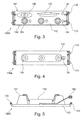
- Figs 3 to 7 show various functional modules that share the same basic design.
- One functional module comprises a carrying plate 132 that by way of coupling elements 133 can be mechanically coupled to the fastening element 112A, 112B of the interior component.
- a functional module comprises functionally specific units that by way of an interface can be coupled to the second connection interface 104 of the interior component.
- the carrying plates 132 of the different functional modules have identical dimensions so that the functional modules can be rearranged at will, i.e. can replace any other functional module at the latter's position without there being a need to rearrange adjacent functional modules.
- Fig. 3 shows a functional module 130A comprising three illumination elements 135, arranged side by side from left to right, so that in the installed state of the functional module 130A their position corresponds to the position of the seats in a seat row comprising three seats.
- the illumination elements can, for example, be reading lights which can be switched on or off by way of an actuating element 134 in the form of a switch or a button.
- Other actuating elements can be provided, for example to call a cabin attendant.
- the functional module 130A comprises a loudspeaker 136 and a display unit 137 for reproducing optical signals.
- Fig. 4 shows a functional module 130B comprising three air outlets 138 that analogous to the illumination elements 135 are arranged side by side and are connected to the second connection interface 104 by way of an air line 139.
- Fig. 5 shows a functional module 130C designed to provide an emergency oxygen supply.
- an oxygen cylinder 140 is arranged that supplies oxygen by way of oxygen masks that are arranged in the housing 141.
- a signal is transmitted to the connection interface 142 by way of the second connection interface 104 so that the oxygen masks drop from the housing 141 into the passenger compartment where they supply passengers with emergency oxygen.
- Fig. 6 shows a functional module 130D with an extendable projection surface 143.
- the projection surface 143 comprises a foldable frame that in the extended state provides stability.
- the projection surface 143 can comprise a gas-inflatable or fillable or fluid-inflatable or fillable frame to achieve stability.
- a coiling element 145 By way of rotary movement of a coiling element 145 the projection surface 143 is extended into the passenger compartment or moved from it.
- the coiling element 145 is driven by way of an actuator 144, for example an electric motor.
- the projection surface 143 can be used to reproduce visual information or to play back an entertainment program. Retracting and extending the projection surface 143 can be controlled by a passenger in relation to the particular projection surface allocated to said passenger, or can be controlled from a central position in relation to all the projection surfaces in the passenger compartment. To this effect the actuator 144 is supplied with electrical energy by way of the second connection interface 104 of the interior component.
- Fig. 7 shows a functional module 130E comprising a projector 146 that is designed to project an image onto the projection surface 143 shown in Fig. 6 .
- the projector receives the image information from the second connection interface 104 by way of the connection interface 142.
Abstract
Description
- The invention relates to an interior component for an aircraft and to an aircraft comprising such an interior component. The interior component comprises a recess in which a multitude of functional modules for supplying one or several passengers are arranged.
- In vehicles designed for passenger transport, in particular for the transport of a plurality of passengers, for example in aircraft, in a passenger compartment functional modules are arranged above the passenger seats, in other words in the overhead region of passengers, which functional modules supply passengers with, for example, light, air, emergency oxygen or information.
- The functional modules form a so-called passenger service unit, PSU. The position of the individual functional modules of the PSU depends among other things on the seat configuration in the passenger compartment. For example, illumination elements must be arranged so that an emitted light cone illuminates the region between two seats arranged one behind another, rather than illuminating the seat. Furthermore, control elements that are arranged in the overhead region must be conveniently accessible to passengers.
- By way of a passenger service channel the functional modules are, for example, supplied with air, electrical energy and control signals. To this effect the functional modules are coupled to the passenger service channel, in particular to lines in the passenger service channel, by way of connection interfaces.
- Usually, during assembly of an aircraft the passenger service channel is routed in a first work step before the seat configuration of the respective aircraft is established. In order to adapt the functional modules of the PSU to the seat configuration, the connection lines of the connection interface of the functional modules on the passenger service channel usually comprise overlength so that they can reach any possible installation position of a functional module in a vehicle.
- Moreover, because of component tolerances of the functional modules slight variations in the final installation position of the functional modules in the aircraft can occur, and for this reason, too, overlengths in the connection lines on the passenger service channel may be required in order to compensate for these tolerance-related variations in the installation position. It may be necessary for the overlengths in the connection lines to be attached to the fuselage structure merely in a specified maximum distance from a functional module in order to avoid non-attached overlength of the lines.
-
WO 2011/079906 A2 andUS 2012/312921 A1 describe a system component module for installation in an aircraft passenger cabin with a carrying device to which a PSU channel and an individual air supply system are attached. A fastening device is designed to fasten the system component module to a base plate of a stowage bin provided in the aircraft passenger cabin. - It may be considered to be the object of the invention to state an interior component with functional modules of a passenger service unit that makes it possible to achieve simpler installation in a vehicle as well as the provision of shorter overlengths of connection lines of the functional modules.
- This object is met by the subject matter of the independent claims. Improvements to the invention are provided in the dependent claims and in the following description.
- According to a first aspect an interior component for an interior room of an aircraft is provided. The interior component comprises a body having a first surface and a second surface. Furthermore, the interior component comprises a multitude of functional modules which form a passenger service unit. The second surface is arranged opposite the first surface and comprises a recess. The multitude of functional modules are arranged one after another in the recess in the longitudinal direction of the interior component, such that a first front surface of the functional module arranged frontally in the longitudinal direction closes flush with a first front surface of the body.
- In this manner the interior component described above and below makes it possible for the functional modules to be installed or fastened with reference to the interior component or its front surface, rather than with reference to the entire passenger compartment.
- If the functional modules are installed with reference to the entire passenger compartment, because of cumulative component tolerances of the functional modules, over the entire length of the passenger compartment of an aircraft this can result in very considerable fluctuation of the positions of the functional modules. These fluctuations can be prevented or reduced in that the functional modules are installed with reference to an interior component. Equipment tolerances thus have an effect only in the region of an interior component.
- If two interior components that are essentially identical are installed one after another in a passenger compartment, component tolerances of the functional modules in an interior component do not have an effect on the position of the functional modules in the second interior component, because the functional modules are arranged such that the front functional module in each case closes flush with a front surface of the interior component.
- A functional module can, in particular, be provided for supplying an entire seat row, in other words seats arranged side by side, so that a functional module can comprise several functional units of the same type that are arranged side by side. Various functions for a seat row are made possible in that various functional modules are arranged one after another and are associated with a seat row.
- Depending on the manner in which the interior component is arranged in the longitudinal direction with reference to the seats or the seat rows, the position or the order of the functional modules in the longitudinal direction of the interior component can vary.
- If the seat configuration is changed to the effect that the seat pitch of seats arranged one after another is increased, the functional modules associated with a seat can also be displaced, and any resulting gaps can be covered by so-called blank modules. The blank modules can be flat elements, for example flat panels without any further function, for merely covering up the resulting gaps.
- The term recess refers to an indentation in the second surface that makes it possible to spatially accommodate the functional modules.
- The notion of closing flush refers to the front functional module in the longitudinal direction of the interior component starting or ending essentially at the same height as the front surface of the interior component without in the longitudinal direction projecting beyond the front surface of the interior component.
- According to one embodiment a second front surface of the rear functional module, when viewed in the longitudinal direction, closes flush with a second front surface of the body.
- Thus the functional modules arranged in the recess of the interior component extend over the entire length of the interior component. If such interior components are installed one after another in the longitudinal direction and if they adjoin, it is possible to provide any desired functional module at any desired position.
- According to a further embodiment the multitude of functional modules comprise an identical extension in the longitudinal direction.
- In this way any two functional modules can be positionally changed without this necessitating a change in the position of the other functional modules. Thus in the case of a change in the seat configuration in the passenger compartment the adaptation expenditure relating to the functional modules of the passenger service unit is reduced.
- According to a further embodiment a functional module extends in a direction across the longitudinal direction over the entire extension of the recess, in other words over the entire width of the recess.
- The recess can, in particular, comprise a constant width so that the functional modules also comprise an identical width.
- According to a further embodiment the length of the body corresponds to an integral multiple of the length of a functional module. In this arrangement the length of the functional module corresponds to its extension in the longitudinal direction of the interior component.
- According to a further embodiment the interior component comprises a fastening element by means of which each functional module of the multitude of functional modules is reversibly mechanically coupled.
- In this arrangement the fastening element is used for positioning the functional module with reference to the interior component. Attachment of the functional modules can take place with non-positive fit or with positive fit as well as with the use of a tool or without the use of a tool.
- According to a further embodiment the fastening element is arranged in the recess.
- According to a further embodiment the fastening element is a fastening rail that extends in the longitudinal direction of the interior component.
- In this embodiment the functional modules can be displaced along the fastening rail in the longitudinal direction of the interior component, provided fastening of the functional modules to the fastening rail allows such movement.
- The functional modules can be attached to the fastening rail in such a manner that the functional modules are held in the recess of the interior component while nevertheless movement along the fastening rail is possible. If a functional module is in its intended position, affixation in the longitudinal direction of the fastening rail can also take place.
- According to a further embodiment the interior component comprises a first interface for connecting the interior component to a passenger service channel.
- Thus the connection lines of the passenger service channel are no longer coupled to the functional modules but instead to the interior component. Thus hitherto existing overlengths of these connection lines can be reduced in that the first interface is arranged on the interior component at a constant position. In terms of connection to the passenger service channel the actual position of the functional modules is immaterial.
- By reducing overlengths in the connection lines of the passenger service channel, overall the weight of a vehicle and the installation space required for cabling and the passenger service channel can be reduced.
- According to a further embodiment the interior component comprises a second interface for connecting the multitude of functional modules to the interior component.
- The functional modules are functionally connected directly to the interior component, i.e., for example, a functional module comprising an air outlet is connected to an air duct; an illumination element is connected to an electrical line; and a display element is connected to a data transfer line.
- According to a further embodiment the second interface is coupled to the first interface so that the functional modules can be coupled indirectly to the passenger service channel.
- The second interface can comprise the different connection lines described above and is connected by way of interconnection lines to the corresponding connection lines of the first interface so that the functional modules can, by way of the interconnection lines, be coupled directly to the passenger service channel.
- Because the functional modules are not directly coupled to the passenger service channel there is no longer any need to provide an overlength in the connection lines of the passenger service channel on account of unforeseeable positions of the functional modules because the passenger service channel is coupled to the first interface of the interior component, whose position is independent of the position of the functional modules.
- According to a further embodiment the multitude of functional modules comprise at least one functional module selected from the group comprising a display element, an illumination element, a ventilation element, an emergency oxygen supply unit, an extendable projection surface and a projector.
- According to a further embodiment the interior component is a hatrack, in other words a stowage shelf or a stowage compartment. In the body of the interior component there is an interior room for accommodating baggage, and on the underside of the baggage compartment the functional modules are arranged in a recess.
- According to a further aspect an aircraft comprising an interior component as described above and below is provided. The aircraft comprises a passenger compartment with a multitude of seats arranged one after another. The interior component is arranged in the passenger compartment above the multitude of seats. By means of a fastening device the interior component is mechanically coupled to a fuselage structure of the aircraft.
- The interior component as described above and below makes it possible to pre-install the functional modules on the interior components that can then be installed in the aircraft together with the functional modules. The position of the first connection interface of the interior component for connection to the passenger service channel is known, and thus it is also possible to affix the connection line of the passenger service channel with reference to the fuselage structure, rather than having to be adjusted depending on the position of a functional module, which position is determined only at a later stage. Because of the design of the interior component it is possible to subsequently alter the position of the functional modules without this requiring the connection line to be positioned anew on the passenger service channel and to be affixed thereto. Thus the required overlength of this connection line can turn out to be shorter.
- Likewise the interior component can be used for retrofitting existing aircraft.
- Below, exemplary embodiments of the invention are described with reference to the figures.
-
-
Fig. 1 shows a diagrammatic view of an aircraft comprising an interior component according to one exemplary embodiment. -
Fig. 2 shows a diagrammatic view of a passenger compartment comprising two interior components according to a further exemplary embodiment. -
Fig. 3 shows a functional module for an interior component according to a further exemplary embodiment. -
Fig. 4 shows a functional module for an interior component according to a further exemplary embodiment. -
Fig. 5 shows a functional module for an interior component according to a further exemplary embodiment. -
Fig. 6 shows a functional module for an interior component according to a further exemplary embodiment. -
Fig. 7 shows a functional module for an interior component according to a further exemplary embodiment. - Detailed description of exemplary embodiments.
- The illustrations are diagrammatic and not to scale. If in the following description of the figures the same reference characters are used, they relate to identical or similar elements.
-
Fig. 1 shows a view of anaircraft 350 comprising afuselage structure 300. Thefuselage structure 300 encloses a passenger compartment in which theinterior component 100 is located. Byway offastening elements 302 theinterior component 100 is mechanically coupled to thefuselage structure 300 and is arranged in an overhead region of the passenger compartment, as is also evident fromFig. 2 , which will be described below. - By way of a
first connection interface 102, which is arranged on afirst surface 106 of thebody 103 of theinterior component 100, theinterior component 100 is connected to apassenger service channel Fig. 1 . To this effect, known interconnection lines and connection technology can be employed. The two dashed positions of the passenger service channel show possible optional positions, wherein the position of the passenger service channel relative to the interior component is irrelevant. - The
interior component 100 comprises asecond surface 108, which is arranged opposite thefirst surface 102 and which points in the direction of the passenger compartment. Thesecond surface 104 comprises arecess 110 which extends in the longitudinal direction of the interior component and is designed to accommodate the functional modules. - In the recess 110 a
second connection interface 104 is arranged, by means of which the functional modules are coupled. It is also possible for several connection interfaces to be arranged in therecess 110. - The
first connection interface 102, which can also be referred to as the connection interface on the aircraft side, and thesecond connection interface 104, which can also be referred to as the connection interface on the functional module side, are interconnected in such a manner that electrical energy, electrical signals or an air flow can be transmitted from the passenger service channel by way of the first connection interface to the second connection interface, and the functional modules can be connected to the second connection interface. - In the
recess 110,fastening elements - It should be pointed out that in the longitudinal direction of the passenger compartment, which direction extends into the drawing plane, several interior components can be arranged one after another in particular so that the front surfaces of adjacent interior components adjoin, and in particular rest one against another. For the sake of clarity, the functional modules are not shown in
Fig. 1 ; however, they are shown in the subsequent figures. - Fastening of the functional modules in the
recess 110 can take place in that the functional modules are pushed, consecutively and in the provided order in the longitudinal direction of the interior component along the fastening rail, to their positions, or alternatively in that the functional modules are fastened from below to the fastening element. -
Fig. 2 shows a diagrammatic lateral view of a passenger compartment. A plurality of seat rows are arranged one after another, with each seat row comprisingseveral seats - Affixed above the seats are two
interior components longitudinal direction 301, with a multitude offunctional modules longitudinal direction 301 on the underside, i.e. thesecond surface 108, of saidinterior components - The foremost
functional module 130A is arranged such that afront surface 147 of thefunctional module 130A closes flush with thefront surface 114 of theinterior component 100A. Thefront surface 148 of the rearmostfunctional module 130E closes flush with thefront surface 116 of theinterior component 100A. - An
interior component length 101 of the interior component extends over three seat rows, thus corresponding to thelength 312 that corresponds to three times thesingle seat pitch 311. - The
length 131 of a functional module is dimensioned such that thelength 101 corresponds to an integral multiple of thelength 131 so that the functional modules cover the entire length of therecess 110. Since the functional modules are identical in length, their order can be selected at will in thelongitudinal direction 301. For example, in theinterior component 100A the functional modules are arranged in theorder interior component 100B the functional modules are arranged in theorder -
Fig. 2 shows a standard seat configuration in which thepitch 311 is, for example, 28 inch (71.12 cm). In this example thepitch 312 and thelength 101 are 84 inch (213.36 cm), and with a total number of 15 functional modules (5 functional modules for each seat row) thelength 131 corresponds to 5.6 inch (14.224 cm). - If the seat configuration, for example the seat pitch, is altered, this may require a change in the positions of the functional modules. Such change can take place in that two functional modules merely swap their positions, or in that a functional module is pushed to some other position after at least one functional module has been removed from the recess.
- The change in the position of a functional module can take place without the functional coupling with the passenger service channel having to be detached and at the target position having to be re-established, and without the connection lines to the passenger service channel first having to be detached from the fuselage structure and having to be fastened anew.
- The interior component as described above and below also makes possible so-called local adaptation of the position of the functional modules without the need for adaptation of the positions of the functional modules in the entire passenger cabin. For example, if the order of the functional modules on the
interior component 100A is altered, the order and the position of the functional modules on theinterior component 100B are not influenced because in each case the functional modules have been installed with reference to an interior component rather than with reference to the passenger compartment or to the fuselage structure. -
Figs 3 to 7 show various functional modules that share the same basic design. One functional module comprises a carryingplate 132 that by way ofcoupling elements 133 can be mechanically coupled to thefastening element second connection interface 104 of the interior component. - The carrying
plates 132 of the different functional modules have identical dimensions so that the functional modules can be rearranged at will, i.e. can replace any other functional module at the latter's position without there being a need to rearrange adjacent functional modules. -
Fig. 3 shows afunctional module 130A comprising threeillumination elements 135, arranged side by side from left to right, so that in the installed state of thefunctional module 130A their position corresponds to the position of the seats in a seat row comprising three seats. The illumination elements can, for example, be reading lights which can be switched on or off by way of anactuating element 134 in the form of a switch or a button. Other actuating elements can be provided, for example to call a cabin attendant. - Apart from the above, the
functional module 130A comprises aloudspeaker 136 and adisplay unit 137 for reproducing optical signals. -
Fig. 4 shows afunctional module 130B comprising threeair outlets 138 that analogous to theillumination elements 135 are arranged side by side and are connected to thesecond connection interface 104 by way of anair line 139. -
Fig. 5 shows afunctional module 130C designed to provide an emergency oxygen supply. To this effect anoxygen cylinder 140 is arranged that supplies oxygen by way of oxygen masks that are arranged in thehousing 141. When oxygen is required, a signal is transmitted to theconnection interface 142 by way of thesecond connection interface 104 so that the oxygen masks drop from thehousing 141 into the passenger compartment where they supply passengers with emergency oxygen. -
Fig. 6 shows afunctional module 130D with anextendable projection surface 143. Theprojection surface 143 comprises a foldable frame that in the extended state provides stability. As an alternative, theprojection surface 143 can comprise a gas-inflatable or fillable or fluid-inflatable or fillable frame to achieve stability. By way of rotary movement of acoiling element 145 theprojection surface 143 is extended into the passenger compartment or moved from it. The coilingelement 145 is driven by way of anactuator 144, for example an electric motor. - The
projection surface 143 can be used to reproduce visual information or to play back an entertainment program. Retracting and extending theprojection surface 143 can be controlled by a passenger in relation to the particular projection surface allocated to said passenger, or can be controlled from a central position in relation to all the projection surfaces in the passenger compartment. To this effect theactuator 144 is supplied with electrical energy by way of thesecond connection interface 104 of the interior component. -
Fig. 7 shows afunctional module 130E comprising aprojector 146 that is designed to project an image onto theprojection surface 143 shown inFig. 6 . The projector receives the image information from thesecond connection interface 104 by way of theconnection interface 142. - In addition, it should be pointed out that "comprising" does not exclude other elements or steps, and "a" or "one" does not exclude a plural number. Furthermore, it should be pointed out that characteristics or steps which have been described with reference to one of the above exemplary embodiments can also be used in combination with other characteristics or steps of other exemplary embodiments described above. Reference characters in the claims are not to be interpreted as limitations.
Claims (12)
- An interior component (100) for an interior room of an aircraft, comprising:a body (103) having a first surface (106) and a second surface (108); anda multitude of functional modules (130A, 130B, 130C, 130D, 130E) which form a passenger service unit;wherein the second surface (108) is arranged opposite the first surface (106);wherein the second surface (108) comprises a recess (110);wherein the multitude of functional modules are arranged one after another in the recess in the longitudinal direction (301) of the interior component, such that a first front surface (147) of the functional module (130A) arranged frontally in the longitudinal direction (301) closes flush with a first front surface (114) of the body (103);wherein the multitude of functional modules comprise an identical extension in the longitudinal direction (301);wherein a length of the body (103) corresponds to an integral multiple of the length of a functional module (130A).
- The interior component (100) of claim 1,
wherein a second front surface (148) of the rear functional module (130E), when viewed in the longitudinal direction (301), closes flush with a second front surface (116) of the body (103). - The interior component (100) of any one of the preceding claims,
wherein a functional module extends in a direction across the longitudinal direction (301) over the entire extension of the recess (110). - The interior component (100) of any one of the preceding claims,
comprising a fastening element (112A, 112B) by means of which each functional module of the multitude of functional modules is reversibly mechanically coupled. - The interior component (100) of claim 4,
wherein the fastening element is arranged in the recess (110). - The interior component (100) of claim 4 or 5,
wherein the fastening element is a fastening rail that extends in the longitudinal direction (301) of the interior component. - The interior component (100) of any one of the preceding claims,
comprising a first interface (102) for connecting the interior component (100) to a passenger service channel (304A, 304B). - The interior component (100) of any one of the preceding claims,
comprising a second interface (104) for connecting the multitude of functional modules to the interior component (100). - The interior component (100) of claim 8,
wherein the second interface (104) is coupled to the first interface (102) so that the functional modules can be coupled indirectly to the passenger service channel. - The interior component (100) of any one of the preceding claims,
wherein the multitude of functional modules comprise at least one functional module selected from the group comprising a display element, an illumination element, a ventilation element, an emergency oxygen supply unit, an extendable projection surface and a projector. - The interior component (100) of any one of the preceding claims,
wherein the interior component is a hatrack. - An aircraft (350) with an interior component (100) of any one of the preceding claims,
comprising a passenger compartment with a multitude of seats (310A, 310B, 310C) arranged one after another;
wherein the interior component is arranged in the passenger compartment above the multitude of seats.
Applications Claiming Priority (1)
| Application Number | Priority Date | Filing Date | Title |
|---|---|---|---|
| DE102014101895.8A DE102014101895A1 (en) | 2014-02-14 | 2014-02-14 | Interior component for a vehicle with a modular passenger supply unit |
Publications (2)
| Publication Number | Publication Date |
|---|---|
| EP2907751A1 true EP2907751A1 (en) | 2015-08-19 |
| EP2907751B1 EP2907751B1 (en) | 2019-06-12 |
Family
ID=52477576
Family Applications (1)
| Application Number | Title | Priority Date | Filing Date |
|---|---|---|---|
| EP15154106.7A Active EP2907751B1 (en) | 2014-02-14 | 2015-02-06 | Interior component for a vehicle with a modular passenger service unit |
Country Status (3)
| Country | Link |
|---|---|
| US (1) | US9688406B2 (en) |
| EP (1) | EP2907751B1 (en) |
| DE (1) | DE102014101895A1 (en) |
Cited By (2)
| Publication number | Priority date | Publication date | Assignee | Title |
|---|---|---|---|---|
| WO2021102884A1 (en) * | 2019-11-29 | 2021-06-03 | 中国商用飞机有限责任公司 | Connecting device and passenger service unit with same |
| EP3868663A1 (en) * | 2020-02-24 | 2021-08-25 | Airbus Operations GmbH | Passenger service unit with a cover, passenger seat area and vehicle with a passenger service unit |
Families Citing this family (4)
| Publication number | Priority date | Publication date | Assignee | Title |
|---|---|---|---|---|
| DE102011110010A1 (en) * | 2011-08-11 | 2013-02-14 | Airbus Operations Gmbh | Passenger supply module with integrated cabin lighting |
| DE202017107834U1 (en) * | 2017-12-21 | 2018-01-12 | Airbus Operations Gmbh | System for monitoring a passenger cabin |
| DE102018001100B4 (en) * | 2018-02-10 | 2021-02-25 | Diehl Aerospace Gmbh | Projection module, passenger cabin and retrofit procedures |
| DE102018010242B4 (en) | 2018-02-10 | 2022-02-03 | Diehl Aerospace Gmbh | Retrofit method for a projection module |
Citations (5)
| Publication number | Priority date | Publication date | Assignee | Title |
|---|---|---|---|---|
| US20100237191A1 (en) * | 2009-03-17 | 2010-09-23 | Airbus Operations Gmbh | Device for storing emergency equipment items in a vehicle |
| WO2011079906A2 (en) | 2009-12-18 | 2011-07-07 | Airbus Operations Gmbh | System component module, and method for mounting a system component module |
| US20110240796A1 (en) * | 2008-11-20 | 2011-10-06 | Airbus Operations Gmbh | Supply unit for flexible supply channels |
| US20130149950A1 (en) * | 2010-04-28 | 2013-06-13 | Airbus Operations Gmbh | Support structure for use in an air supply arrangement and service supply system comprising said type of support structure and method for configuration |
| EP2657132A2 (en) * | 2012-04-25 | 2013-10-30 | Airbus Operations GmbH | Passenger service system with improved air guidance |
Family Cites Families (8)
| Publication number | Priority date | Publication date | Assignee | Title |
|---|---|---|---|---|
| DE102007014406B3 (en) * | 2007-03-26 | 2008-04-24 | Airbus Deutschland Gmbh | Supply channel for supplying fresh air and/or air-conditioned air to seat of vehicle i.e. airplane, has air shower designed for sealingly fitting at mantle surface of hollow profile in area of air inlet |
| DE102009008543B4 (en) | 2009-02-11 | 2014-05-22 | Airbus Operations Gmbh | Interior projection for aircraft |
| DE102009014599A1 (en) | 2009-03-24 | 2010-09-30 | Airbus Deutschland Gmbh | Integration of supply functions in a storage compartment |
| DE102009051362A1 (en) | 2009-10-30 | 2011-05-05 | Airbus Operations Gmbh | Storage compartment module with integral supply channel for optimized installation |
| DE102009058801B4 (en) | 2009-12-18 | 2017-07-13 | Airbus Operations Gmbh | Multifunctional supply profile |
| DE102010034410A1 (en) * | 2010-08-14 | 2012-02-16 | Diehl Aerospace Gmbh | Supply device for passenger cabin, particularly for aircraft passenger cabin, comprises hood body, functional unit and supply duct which is attached on passenger facing side, where hood body comprises operating section |
| US20120074258A1 (en) * | 2010-09-23 | 2012-03-29 | Be Intellectual Property, Inc. | Integrated aircraft interior |
| DE102012017349A1 (en) | 2012-08-31 | 2014-03-06 | Airbus Operations Gmbh | Air transmission system for flexible passenger supply units |
-
2014
- 2014-02-14 DE DE102014101895.8A patent/DE102014101895A1/en not_active Withdrawn
-
2015
- 2015-02-06 EP EP15154106.7A patent/EP2907751B1/en active Active
- 2015-02-13 US US14/622,029 patent/US9688406B2/en active Active
Patent Citations (6)
| Publication number | Priority date | Publication date | Assignee | Title |
|---|---|---|---|---|
| US20110240796A1 (en) * | 2008-11-20 | 2011-10-06 | Airbus Operations Gmbh | Supply unit for flexible supply channels |
| US20100237191A1 (en) * | 2009-03-17 | 2010-09-23 | Airbus Operations Gmbh | Device for storing emergency equipment items in a vehicle |
| WO2011079906A2 (en) | 2009-12-18 | 2011-07-07 | Airbus Operations Gmbh | System component module, and method for mounting a system component module |
| US20120312921A1 (en) | 2009-12-18 | 2012-12-13 | Grosse-Plankermann Peter | System component module and method for mounting a system component module |
| US20130149950A1 (en) * | 2010-04-28 | 2013-06-13 | Airbus Operations Gmbh | Support structure for use in an air supply arrangement and service supply system comprising said type of support structure and method for configuration |
| EP2657132A2 (en) * | 2012-04-25 | 2013-10-30 | Airbus Operations GmbH | Passenger service system with improved air guidance |
Cited By (3)
| Publication number | Priority date | Publication date | Assignee | Title |
|---|---|---|---|---|
| WO2021102884A1 (en) * | 2019-11-29 | 2021-06-03 | 中国商用飞机有限责任公司 | Connecting device and passenger service unit with same |
| EP3868663A1 (en) * | 2020-02-24 | 2021-08-25 | Airbus Operations GmbH | Passenger service unit with a cover, passenger seat area and vehicle with a passenger service unit |
| US11572171B2 (en) * | 2020-02-24 | 2023-02-07 | Airbus Operations Gmbh | Passenger service unit having a covering, passenger seating area and vehicle having a passenger service unit |
Also Published As
| Publication number | Publication date |
|---|---|
| DE102014101895A1 (en) | 2015-08-20 |
| US20150232182A1 (en) | 2015-08-20 |
| EP2907751B1 (en) | 2019-06-12 |
| US9688406B2 (en) | 2017-06-27 |
Similar Documents
| Publication | Publication Date | Title |
|---|---|---|
| EP2907751B1 (en) | Interior component for a vehicle with a modular passenger service unit | |
| US9499270B2 (en) | Supply module for passenger transport vehicles | |
| EP3068133B1 (en) | Unique system and method of creating scenes within a moving vehicle such as an aircraft | |
| US9067683B2 (en) | Support structure for use in an air supply arrangement and service supply system comprising said type of support structure and method for configuration | |
| US8851420B2 (en) | Integration of supply functions in a storage compartment | |
| DE102011116884B4 (en) | Passenger service module and passenger service system | |
| US10723459B2 (en) | Modular overhead bin | |
| US7232094B2 (en) | Method and device for adapting the seat row arrangement in passenger planes according to need | |
| US9527479B2 (en) | Passenger services provisioning for a means of transport | |
| US20110147520A1 (en) | Multi functional supply profile | |
| CA2632276A1 (en) | Module for an aircraft | |
| DE102010018896A1 (en) | Passenger supply arrangement for an airplane | |
| US8814090B2 (en) | Cabin equipment component connection system and method for modifying passenger cabin configuration | |
| US9789962B2 (en) | Passenger service module with integrated cabin lighting | |
| US10882619B2 (en) | Space optimized cabin arrangement for a vehicle as well as a passenger cabin having a plurality of seats and such a cabin arrangement | |
| US9834309B2 (en) | Air transmission system for flexible passenger supply units | |
| US9365156B2 (en) | Lighting apparatus and vehicle | |
| DE102010034410A1 (en) | Supply device for passenger cabin, particularly for aircraft passenger cabin, comprises hood body, functional unit and supply duct which is attached on passenger facing side, where hood body comprises operating section | |
| WO2021165699A1 (en) | Display apparatus | |
| EP2832642A1 (en) | Storage device comprising a luggage bin and an emergency oxygen unit | |
| US20120019944A1 (en) | Mirror arrangement for monitoring a passenger cabin of an aircraft |
Legal Events
| Date | Code | Title | Description |
|---|---|---|---|
| PUAI | Public reference made under article 153(3) epc to a published international application that has entered the european phase |
Free format text: ORIGINAL CODE: 0009012 |
|
| AK | Designated contracting states |
Kind code of ref document: A1 Designated state(s): AL AT BE BG CH CY CZ DE DK EE ES FI FR GB GR HR HU IE IS IT LI LT LU LV MC MK MT NL NO PL PT RO RS SE SI SK SM TR |
|
| AX | Request for extension of the european patent |
Extension state: BA ME |
|
| 17P | Request for examination filed |
Effective date: 20160126 |
|
| RBV | Designated contracting states (corrected) |
Designated state(s): AL AT BE BG CH CY CZ DE DK EE ES FI FR GB GR HR HU IE IS IT LI LT LU LV MC MK MT NL NO PL PT RO RS SE SI SK SM TR |
|
| STAA | Information on the status of an ep patent application or granted ep patent |
Free format text: STATUS: EXAMINATION IS IN PROGRESS |
|
| 17Q | First examination report despatched |
Effective date: 20180516 |
|
| GRAP | Despatch of communication of intention to grant a patent |
Free format text: ORIGINAL CODE: EPIDOSNIGR1 |
|
| STAA | Information on the status of an ep patent application or granted ep patent |
Free format text: STATUS: GRANT OF PATENT IS INTENDED |
|
| INTG | Intention to grant announced |
Effective date: 20190218 |
|
| GRAS | Grant fee paid |
Free format text: ORIGINAL CODE: EPIDOSNIGR3 |
|
| GRAA | (expected) grant |
Free format text: ORIGINAL CODE: 0009210 |
|
| STAA | Information on the status of an ep patent application or granted ep patent |
Free format text: STATUS: THE PATENT HAS BEEN GRANTED |
|
| AK | Designated contracting states |
Kind code of ref document: B1 Designated state(s): AL AT BE BG CH CY CZ DE DK EE ES FI FR GB GR HR HU IE IS IT LI LT LU LV MC MK MT NL NO PL PT RO RS SE SI SK SM TR |
|
| REG | Reference to a national code |
Ref country code: GB Ref legal event code: FG4D |
|
| REG | Reference to a national code |
Ref country code: CH Ref legal event code: EP |
|
| REG | Reference to a national code |
Ref country code: AT Ref legal event code: REF Ref document number: 1142234 Country of ref document: AT Kind code of ref document: T Effective date: 20190615 |
|
| REG | Reference to a national code |
Ref country code: DE Ref legal event code: R096 Ref document number: 602015031617 Country of ref document: DE |
|
| REG | Reference to a national code |
Ref country code: IE Ref legal event code: FG4D |
|
| REG | Reference to a national code |
Ref country code: NL Ref legal event code: MP Effective date: 20190612 |
|
| REG | Reference to a national code |
Ref country code: LT Ref legal event code: MG4D |
|
| PG25 | Lapsed in a contracting state [announced via postgrant information from national office to epo] |
Ref country code: NO Free format text: LAPSE BECAUSE OF FAILURE TO SUBMIT A TRANSLATION OF THE DESCRIPTION OR TO PAY THE FEE WITHIN THE PRESCRIBED TIME-LIMIT Effective date: 20190912 Ref country code: FI Free format text: LAPSE BECAUSE OF FAILURE TO SUBMIT A TRANSLATION OF THE DESCRIPTION OR TO PAY THE FEE WITHIN THE PRESCRIBED TIME-LIMIT Effective date: 20190612 Ref country code: AL Free format text: LAPSE BECAUSE OF FAILURE TO SUBMIT A TRANSLATION OF THE DESCRIPTION OR TO PAY THE FEE WITHIN THE PRESCRIBED TIME-LIMIT Effective date: 20190612 Ref country code: HR Free format text: LAPSE BECAUSE OF FAILURE TO SUBMIT A TRANSLATION OF THE DESCRIPTION OR TO PAY THE FEE WITHIN THE PRESCRIBED TIME-LIMIT Effective date: 20190612 Ref country code: SE Free format text: LAPSE BECAUSE OF FAILURE TO SUBMIT A TRANSLATION OF THE DESCRIPTION OR TO PAY THE FEE WITHIN THE PRESCRIBED TIME-LIMIT Effective date: 20190612 Ref country code: LT Free format text: LAPSE BECAUSE OF FAILURE TO SUBMIT A TRANSLATION OF THE DESCRIPTION OR TO PAY THE FEE WITHIN THE PRESCRIBED TIME-LIMIT Effective date: 20190612 |
|
| PG25 | Lapsed in a contracting state [announced via postgrant information from national office to epo] |
Ref country code: GR Free format text: LAPSE BECAUSE OF FAILURE TO SUBMIT A TRANSLATION OF THE DESCRIPTION OR TO PAY THE FEE WITHIN THE PRESCRIBED TIME-LIMIT Effective date: 20190913 Ref country code: BG Free format text: LAPSE BECAUSE OF FAILURE TO SUBMIT A TRANSLATION OF THE DESCRIPTION OR TO PAY THE FEE WITHIN THE PRESCRIBED TIME-LIMIT Effective date: 20190912 Ref country code: RS Free format text: LAPSE BECAUSE OF FAILURE TO SUBMIT A TRANSLATION OF THE DESCRIPTION OR TO PAY THE FEE WITHIN THE PRESCRIBED TIME-LIMIT Effective date: 20190612 Ref country code: LV Free format text: LAPSE BECAUSE OF FAILURE TO SUBMIT A TRANSLATION OF THE DESCRIPTION OR TO PAY THE FEE WITHIN THE PRESCRIBED TIME-LIMIT Effective date: 20190612 |
|
| REG | Reference to a national code |
Ref country code: AT Ref legal event code: MK05 Ref document number: 1142234 Country of ref document: AT Kind code of ref document: T Effective date: 20190612 |
|
| PG25 | Lapsed in a contracting state [announced via postgrant information from national office to epo] |
Ref country code: CZ Free format text: LAPSE BECAUSE OF FAILURE TO SUBMIT A TRANSLATION OF THE DESCRIPTION OR TO PAY THE FEE WITHIN THE PRESCRIBED TIME-LIMIT Effective date: 20190612 Ref country code: RO Free format text: LAPSE BECAUSE OF FAILURE TO SUBMIT A TRANSLATION OF THE DESCRIPTION OR TO PAY THE FEE WITHIN THE PRESCRIBED TIME-LIMIT Effective date: 20190612 Ref country code: AT Free format text: LAPSE BECAUSE OF FAILURE TO SUBMIT A TRANSLATION OF THE DESCRIPTION OR TO PAY THE FEE WITHIN THE PRESCRIBED TIME-LIMIT Effective date: 20190612 Ref country code: EE Free format text: LAPSE BECAUSE OF FAILURE TO SUBMIT A TRANSLATION OF THE DESCRIPTION OR TO PAY THE FEE WITHIN THE PRESCRIBED TIME-LIMIT Effective date: 20190612 Ref country code: NL Free format text: LAPSE BECAUSE OF FAILURE TO SUBMIT A TRANSLATION OF THE DESCRIPTION OR TO PAY THE FEE WITHIN THE PRESCRIBED TIME-LIMIT Effective date: 20190612 Ref country code: SK Free format text: LAPSE BECAUSE OF FAILURE TO SUBMIT A TRANSLATION OF THE DESCRIPTION OR TO PAY THE FEE WITHIN THE PRESCRIBED TIME-LIMIT Effective date: 20190612 Ref country code: PT Free format text: LAPSE BECAUSE OF FAILURE TO SUBMIT A TRANSLATION OF THE DESCRIPTION OR TO PAY THE FEE WITHIN THE PRESCRIBED TIME-LIMIT Effective date: 20191014 |
|
| PG25 | Lapsed in a contracting state [announced via postgrant information from national office to epo] |
Ref country code: IT Free format text: LAPSE BECAUSE OF FAILURE TO SUBMIT A TRANSLATION OF THE DESCRIPTION OR TO PAY THE FEE WITHIN THE PRESCRIBED TIME-LIMIT Effective date: 20190612 Ref country code: IS Free format text: LAPSE BECAUSE OF FAILURE TO SUBMIT A TRANSLATION OF THE DESCRIPTION OR TO PAY THE FEE WITHIN THE PRESCRIBED TIME-LIMIT Effective date: 20191012 Ref country code: SM Free format text: LAPSE BECAUSE OF FAILURE TO SUBMIT A TRANSLATION OF THE DESCRIPTION OR TO PAY THE FEE WITHIN THE PRESCRIBED TIME-LIMIT Effective date: 20190612 Ref country code: ES Free format text: LAPSE BECAUSE OF FAILURE TO SUBMIT A TRANSLATION OF THE DESCRIPTION OR TO PAY THE FEE WITHIN THE PRESCRIBED TIME-LIMIT Effective date: 20190612 |
|
| REG | Reference to a national code |
Ref country code: DE Ref legal event code: R097 Ref document number: 602015031617 Country of ref document: DE |
|
| PG25 | Lapsed in a contracting state [announced via postgrant information from national office to epo] |
Ref country code: TR Free format text: LAPSE BECAUSE OF FAILURE TO SUBMIT A TRANSLATION OF THE DESCRIPTION OR TO PAY THE FEE WITHIN THE PRESCRIBED TIME-LIMIT Effective date: 20190612 |
|
| PLBE | No opposition filed within time limit |
Free format text: ORIGINAL CODE: 0009261 |
|
| STAA | Information on the status of an ep patent application or granted ep patent |
Free format text: STATUS: NO OPPOSITION FILED WITHIN TIME LIMIT |
|
| PG25 | Lapsed in a contracting state [announced via postgrant information from national office to epo] |
Ref country code: DK Free format text: LAPSE BECAUSE OF FAILURE TO SUBMIT A TRANSLATION OF THE DESCRIPTION OR TO PAY THE FEE WITHIN THE PRESCRIBED TIME-LIMIT Effective date: 20190612 Ref country code: PL Free format text: LAPSE BECAUSE OF FAILURE TO SUBMIT A TRANSLATION OF THE DESCRIPTION OR TO PAY THE FEE WITHIN THE PRESCRIBED TIME-LIMIT Effective date: 20190612 |
|
| 26N | No opposition filed |
Effective date: 20200313 |
|
| PG25 | Lapsed in a contracting state [announced via postgrant information from national office to epo] |
Ref country code: SI Free format text: LAPSE BECAUSE OF FAILURE TO SUBMIT A TRANSLATION OF THE DESCRIPTION OR TO PAY THE FEE WITHIN THE PRESCRIBED TIME-LIMIT Effective date: 20190612 Ref country code: IS Free format text: LAPSE BECAUSE OF FAILURE TO SUBMIT A TRANSLATION OF THE DESCRIPTION OR TO PAY THE FEE WITHIN THE PRESCRIBED TIME-LIMIT Effective date: 20200224 |
|
| PG2D | Information on lapse in contracting state deleted |
Ref country code: IS |
|
| REG | Reference to a national code |
Ref country code: CH Ref legal event code: PL |
|
| REG | Reference to a national code |
Ref country code: BE Ref legal event code: MM Effective date: 20200229 |
|
| PG25 | Lapsed in a contracting state [announced via postgrant information from national office to epo] |
Ref country code: LU Free format text: LAPSE BECAUSE OF NON-PAYMENT OF DUE FEES Effective date: 20200206 Ref country code: MC Free format text: LAPSE BECAUSE OF FAILURE TO SUBMIT A TRANSLATION OF THE DESCRIPTION OR TO PAY THE FEE WITHIN THE PRESCRIBED TIME-LIMIT Effective date: 20190612 |
|
| PG25 | Lapsed in a contracting state [announced via postgrant information from national office to epo] |
Ref country code: CH Free format text: LAPSE BECAUSE OF NON-PAYMENT OF DUE FEES Effective date: 20200229 Ref country code: LI Free format text: LAPSE BECAUSE OF NON-PAYMENT OF DUE FEES Effective date: 20200229 |
|
| PG25 | Lapsed in a contracting state [announced via postgrant information from national office to epo] |
Ref country code: IE Free format text: LAPSE BECAUSE OF NON-PAYMENT OF DUE FEES Effective date: 20200206 |
|
| PG25 | Lapsed in a contracting state [announced via postgrant information from national office to epo] |
Ref country code: BE Free format text: LAPSE BECAUSE OF NON-PAYMENT OF DUE FEES Effective date: 20200229 |
|
| PG25 | Lapsed in a contracting state [announced via postgrant information from national office to epo] |
Ref country code: MT Free format text: LAPSE BECAUSE OF FAILURE TO SUBMIT A TRANSLATION OF THE DESCRIPTION OR TO PAY THE FEE WITHIN THE PRESCRIBED TIME-LIMIT Effective date: 20190612 Ref country code: CY Free format text: LAPSE BECAUSE OF FAILURE TO SUBMIT A TRANSLATION OF THE DESCRIPTION OR TO PAY THE FEE WITHIN THE PRESCRIBED TIME-LIMIT Effective date: 20190612 |
|
| PG25 | Lapsed in a contracting state [announced via postgrant information from national office to epo] |
Ref country code: MK Free format text: LAPSE BECAUSE OF FAILURE TO SUBMIT A TRANSLATION OF THE DESCRIPTION OR TO PAY THE FEE WITHIN THE PRESCRIBED TIME-LIMIT Effective date: 20190612 |
|
| PGFP | Annual fee paid to national office [announced via postgrant information from national office to epo] |
Ref country code: FR Payment date: 20230221 Year of fee payment: 9 |
|
| PGFP | Annual fee paid to national office [announced via postgrant information from national office to epo] |
Ref country code: GB Payment date: 20230221 Year of fee payment: 9 Ref country code: DE Payment date: 20230216 Year of fee payment: 9 |