EP3868545B1 - 3d printing of an intraocular lens having smooth, curved surfaces - Google Patents
3d printing of an intraocular lens having smooth, curved surfaces Download PDFInfo
- Publication number
- EP3868545B1 EP3868545B1 EP21168614.2A EP21168614A EP3868545B1 EP 3868545 B1 EP3868545 B1 EP 3868545B1 EP 21168614 A EP21168614 A EP 21168614A EP 3868545 B1 EP3868545 B1 EP 3868545B1
- Authority
- EP
- European Patent Office
- Prior art keywords
- light source
- photopolymer resin
- curing
- source assembly
- bath
- Prior art date
- Legal status (The legal status is an assumption and is not a legal conclusion. Google has not performed a legal analysis and makes no representation as to the accuracy of the status listed.)
- Active
Links
- 239000011347 resin Substances 0.000 claims description 33
- 229920005989 resin Polymers 0.000 claims description 33
- 238000000034 method Methods 0.000 claims description 27
- 238000004519 manufacturing process Methods 0.000 claims description 19
- 230000007246 mechanism Effects 0.000 claims description 18
- 239000000654 additive Substances 0.000 claims description 17
- 230000000996 additive effect Effects 0.000 claims description 17
- 230000008569 process Effects 0.000 claims description 14
- 230000001360 synchronised effect Effects 0.000 claims description 7
- 229920000642 polymer Polymers 0.000 claims description 6
- 230000008859 change Effects 0.000 claims description 3
- 238000001723 curing Methods 0.000 description 25
- 239000010410 layer Substances 0.000 description 12
- 230000003287 optical effect Effects 0.000 description 7
- 238000010146 3D printing Methods 0.000 description 6
- 238000010586 diagram Methods 0.000 description 6
- 230000005855 radiation Effects 0.000 description 5
- 230000001419 dependent effect Effects 0.000 description 3
- 239000007788 liquid Substances 0.000 description 3
- 239000000463 material Substances 0.000 description 3
- 239000007787 solid Substances 0.000 description 3
- 239000002537 cosmetic Substances 0.000 description 2
- 238000003491 array Methods 0.000 description 1
- 238000010276 construction Methods 0.000 description 1
- 230000005284 excitation Effects 0.000 description 1
- 238000005286 illumination Methods 0.000 description 1
- 239000003999 initiator Substances 0.000 description 1
- 239000011344 liquid material Substances 0.000 description 1
- 238000001459 lithography Methods 0.000 description 1
- 235000015250 liver sausages Nutrition 0.000 description 1
- 238000012986 modification Methods 0.000 description 1
- 230000004048 modification Effects 0.000 description 1
- 239000000178 monomer Substances 0.000 description 1
- 230000035515 penetration Effects 0.000 description 1
- 238000000016 photochemical curing Methods 0.000 description 1
- 239000002356 single layer Substances 0.000 description 1
- 238000001228 spectrum Methods 0.000 description 1
Images


Classifications
-
- B—PERFORMING OPERATIONS; TRANSPORTING
- B29—WORKING OF PLASTICS; WORKING OF SUBSTANCES IN A PLASTIC STATE IN GENERAL
- B29C—SHAPING OR JOINING OF PLASTICS; SHAPING OF MATERIAL IN A PLASTIC STATE, NOT OTHERWISE PROVIDED FOR; AFTER-TREATMENT OF THE SHAPED PRODUCTS, e.g. REPAIRING
- B29C64/00—Additive manufacturing, i.e. manufacturing of three-dimensional [3D] objects by additive deposition, additive agglomeration or additive layering, e.g. by 3D printing, stereolithography or selective laser sintering
- B29C64/10—Processes of additive manufacturing
- B29C64/106—Processes of additive manufacturing using only liquids or viscous materials, e.g. depositing a continuous bead of viscous material
- B29C64/124—Processes of additive manufacturing using only liquids or viscous materials, e.g. depositing a continuous bead of viscous material using layers of liquid which are selectively solidified
- B29C64/129—Processes of additive manufacturing using only liquids or viscous materials, e.g. depositing a continuous bead of viscous material using layers of liquid which are selectively solidified characterised by the energy source therefor, e.g. by global irradiation combined with a mask
- B29C64/135—Processes of additive manufacturing using only liquids or viscous materials, e.g. depositing a continuous bead of viscous material using layers of liquid which are selectively solidified characterised by the energy source therefor, e.g. by global irradiation combined with a mask the energy source being concentrated, e.g. scanning lasers or focused light sources
-
- B—PERFORMING OPERATIONS; TRANSPORTING
- B29—WORKING OF PLASTICS; WORKING OF SUBSTANCES IN A PLASTIC STATE IN GENERAL
- B29C—SHAPING OR JOINING OF PLASTICS; SHAPING OF MATERIAL IN A PLASTIC STATE, NOT OTHERWISE PROVIDED FOR; AFTER-TREATMENT OF THE SHAPED PRODUCTS, e.g. REPAIRING
- B29C64/00—Additive manufacturing, i.e. manufacturing of three-dimensional [3D] objects by additive deposition, additive agglomeration or additive layering, e.g. by 3D printing, stereolithography or selective laser sintering
- B29C64/20—Apparatus for additive manufacturing; Details thereof or accessories therefor
- B29C64/264—Arrangements for irradiation
-
- A—HUMAN NECESSITIES
- A61—MEDICAL OR VETERINARY SCIENCE; HYGIENE
- A61F—FILTERS IMPLANTABLE INTO BLOOD VESSELS; PROSTHESES; DEVICES PROVIDING PATENCY TO, OR PREVENTING COLLAPSING OF, TUBULAR STRUCTURES OF THE BODY, e.g. STENTS; ORTHOPAEDIC, NURSING OR CONTRACEPTIVE DEVICES; FOMENTATION; TREATMENT OR PROTECTION OF EYES OR EARS; BANDAGES, DRESSINGS OR ABSORBENT PADS; FIRST-AID KITS
- A61F2/00—Filters implantable into blood vessels; Prostheses, i.e. artificial substitutes or replacements for parts of the body; Appliances for connecting them with the body; Devices providing patency to, or preventing collapsing of, tubular structures of the body, e.g. stents
- A61F2/02—Prostheses implantable into the body
- A61F2/14—Eye parts, e.g. lenses, corneal implants; Implanting instruments specially adapted therefor; Artificial eyes
- A61F2/16—Intraocular lenses
-
- B—PERFORMING OPERATIONS; TRANSPORTING
- B29—WORKING OF PLASTICS; WORKING OF SUBSTANCES IN A PLASTIC STATE IN GENERAL
- B29C—SHAPING OR JOINING OF PLASTICS; SHAPING OF MATERIAL IN A PLASTIC STATE, NOT OTHERWISE PROVIDED FOR; AFTER-TREATMENT OF THE SHAPED PRODUCTS, e.g. REPAIRING
- B29C64/00—Additive manufacturing, i.e. manufacturing of three-dimensional [3D] objects by additive deposition, additive agglomeration or additive layering, e.g. by 3D printing, stereolithography or selective laser sintering
- B29C64/20—Apparatus for additive manufacturing; Details thereof or accessories therefor
- B29C64/227—Driving means
-
- B—PERFORMING OPERATIONS; TRANSPORTING
- B29—WORKING OF PLASTICS; WORKING OF SUBSTANCES IN A PLASTIC STATE IN GENERAL
- B29C—SHAPING OR JOINING OF PLASTICS; SHAPING OF MATERIAL IN A PLASTIC STATE, NOT OTHERWISE PROVIDED FOR; AFTER-TREATMENT OF THE SHAPED PRODUCTS, e.g. REPAIRING
- B29C64/00—Additive manufacturing, i.e. manufacturing of three-dimensional [3D] objects by additive deposition, additive agglomeration or additive layering, e.g. by 3D printing, stereolithography or selective laser sintering
- B29C64/20—Apparatus for additive manufacturing; Details thereof or accessories therefor
- B29C64/245—Platforms or substrates
-
- B—PERFORMING OPERATIONS; TRANSPORTING
- B29—WORKING OF PLASTICS; WORKING OF SUBSTANCES IN A PLASTIC STATE IN GENERAL
- B29C—SHAPING OR JOINING OF PLASTICS; SHAPING OF MATERIAL IN A PLASTIC STATE, NOT OTHERWISE PROVIDED FOR; AFTER-TREATMENT OF THE SHAPED PRODUCTS, e.g. REPAIRING
- B29C64/00—Additive manufacturing, i.e. manufacturing of three-dimensional [3D] objects by additive deposition, additive agglomeration or additive layering, e.g. by 3D printing, stereolithography or selective laser sintering
- B29C64/20—Apparatus for additive manufacturing; Details thereof or accessories therefor
- B29C64/255—Enclosures for the building material, e.g. powder containers
-
- B—PERFORMING OPERATIONS; TRANSPORTING
- B29—WORKING OF PLASTICS; WORKING OF SUBSTANCES IN A PLASTIC STATE IN GENERAL
- B29D—PRODUCING PARTICULAR ARTICLES FROM PLASTICS OR FROM SUBSTANCES IN A PLASTIC STATE
- B29D11/00—Producing optical elements, e.g. lenses or prisms
- B29D11/00009—Production of simple or compound lenses
-
- B—PERFORMING OPERATIONS; TRANSPORTING
- B29—WORKING OF PLASTICS; WORKING OF SUBSTANCES IN A PLASTIC STATE IN GENERAL
- B29D—PRODUCING PARTICULAR ARTICLES FROM PLASTICS OR FROM SUBSTANCES IN A PLASTIC STATE
- B29D11/00—Producing optical elements, e.g. lenses or prisms
- B29D11/02—Artificial eyes from organic plastic material
- B29D11/023—Implants for natural eyes
-
- B—PERFORMING OPERATIONS; TRANSPORTING
- B33—ADDITIVE MANUFACTURING TECHNOLOGY
- B33Y—ADDITIVE MANUFACTURING, i.e. MANUFACTURING OF THREE-DIMENSIONAL [3-D] OBJECTS BY ADDITIVE DEPOSITION, ADDITIVE AGGLOMERATION OR ADDITIVE LAYERING, e.g. BY 3-D PRINTING, STEREOLITHOGRAPHY OR SELECTIVE LASER SINTERING
- B33Y10/00—Processes of additive manufacturing
-
- B—PERFORMING OPERATIONS; TRANSPORTING
- B33—ADDITIVE MANUFACTURING TECHNOLOGY
- B33Y—ADDITIVE MANUFACTURING, i.e. MANUFACTURING OF THREE-DIMENSIONAL [3-D] OBJECTS BY ADDITIVE DEPOSITION, ADDITIVE AGGLOMERATION OR ADDITIVE LAYERING, e.g. BY 3-D PRINTING, STEREOLITHOGRAPHY OR SELECTIVE LASER SINTERING
- B33Y30/00—Apparatus for additive manufacturing; Details thereof or accessories therefor
-
- A—HUMAN NECESSITIES
- A61—MEDICAL OR VETERINARY SCIENCE; HYGIENE
- A61F—FILTERS IMPLANTABLE INTO BLOOD VESSELS; PROSTHESES; DEVICES PROVIDING PATENCY TO, OR PREVENTING COLLAPSING OF, TUBULAR STRUCTURES OF THE BODY, e.g. STENTS; ORTHOPAEDIC, NURSING OR CONTRACEPTIVE DEVICES; FOMENTATION; TREATMENT OR PROTECTION OF EYES OR EARS; BANDAGES, DRESSINGS OR ABSORBENT PADS; FIRST-AID KITS
- A61F2240/00—Manufacturing or designing of prostheses classified in groups A61F2/00 - A61F2/26 or A61F2/82 or A61F9/00 or A61F11/00 or subgroups thereof
- A61F2240/001—Designing or manufacturing processes
- A61F2240/002—Designing or making customized prostheses
Definitions
- adjustment of the variable aperture and continuous movement of the platform 106 relative to the curing plane 124 may allow for the generation of parts (e.g., IOLs) having smooth curved surfaces.
Description
- This present disclosure relates generally 3D printing and, more particularly, to 3D printing of intraocular lenses having smooth, curved surfaces.
- 3D printing, also known as additive manufacturing, refers to processes used to create a three-dimensional object in which successive layers of material are formed under computer control to create an object. There are several 3D printing processes that differ in the way layers are deposited to create parts and in the materials that are used. Stereolithography (SLA) is a type of 3D printing process that produces layers of a solid part by curing liquid materials using photopolymerization. This is a process by which a vat of liquid polymer is exposed to light, causing chains of molecules to link together and form polymers that comprise one layer of a three-dimensional solid object. A build plate on which the solid object rests, is then moved down in small increments and the liquid polymer is again exposed to light. The process repeats until a model of the object is complete.
- Current SLA 3D printers use an image-forming projection system (e.g., a digital micromirror device (DMD), lithography, LCD, raster scan and the like) to project an image on to a particular plane of a photopolymer bath. These systems are meant for creating complex shapes and so require an adaptable image to cure the material. However, most image-forming projection systems utilize pixels to project the image, and thus the projected image has a resolution limitation in a transverse plane related to the pixel size. Additionally, stepper motors for translating the build pate results in the curing of fixed incremental layer steps, resulting in a "stair-stepped" surface finish on the part, instead of a part having smooth surfaces. Due to these limitations, current SLA 3D printers may not be suitable for production of intraocular lenses (IOLs) as the "stair steps" can reduce optical quality and cosmetic appearance.
- Accordingly, what is needed is an improved 3D printing system suitable for producing miniature optics, including IOLs, having smooth, continuously curved surfaces. Document
US 2004/0061620 A1 discloses a device and a method for the layer-by-layer generative manufacturing of three-dimensional objects by selective hardening of a previously applied layer by means of laser radiation, wherein a laser contains a switching device for changing the modal composition of the laser radiation. By changing the modal composition of the radiation during the selective hardening of a layer, the focussing features of the radiation is increased in areas, in which high structural accuracy is required. In the remaining areas to be illuminated, the required illumination time is reduced by increasing the intensity of the radiation. - In accordance with the invention, a continuous additive fabrication system is suggested as it is specified by the features of independent claim 1. Advantageous features of the system are the subject of dependent claim 2.
- Also in accordance with the invention, a method for continuous additive fabrication is suggested as it is specified by the features of independent method claim 3. Advantageous features of the method are the subject of dependent method claim 4.
- The above-described systems and methods may provide certain advantages over conventional additive manufacturing techniques. For example, the above-described systems and methods may allow for the generation of smooth, high-resolution, optical-quality services, suitable for IOLs.
- For a more complete understanding of the present disclosure and the advantages thereof, reference is now made to the following description taken in conjunction with the accompanying drawings in which like reference numerals indicate like features and wherein:
-
FIG. 1 is a diagram illustrating a portion of an example conventional SLA additive fabrication system; -
FIG. 2 is a diagram illustrating a continuous additive fabrication system in accordance with exemplary embodiments of the present invention; and -
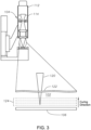
FIG. 3 is a cross-section diagram of light source assembly showing the light source and the motorized variable aperture. -
FIG. 1 is a diagram illustrating a portion of an example conventional SLA additive fabrication system. The example SLAadditive fabrication system 10, e.g., a conventional SLA 3D printer, includes a digital micromirror device (DMD) 12 or other image-forming projection system, to projectimages 14 on to atransverse plane 16 of a bath ofphotopolymer resin 18. Typically, theimages 14 are projected by theDMD 12 by focusing an ultraviolet (UV) light/laser (not shown) on to thetransverse plane 16 ofphotopolymer resin 18. A DMD chip comprises several hundred thousand microscopic mirrors on its surface arranged in an array corresponding to the pixels in theimage 14 to be displayed. The ultraviolet light projected by the DMD causes the photosensitive photopolymer to solidify to form a layer of the cured polymer defining the resulting part. However, because theDMD 12 is made up of pixels, the projectedimages 14 have a resolution limitation in thetransverse plane 16 related to the pixel size of theDMD 12, resulting in "stair-stepped" edges of theimages 14, as shown. - Additionally, stepper motors (not shown) translate an elevator apparatus or platform up or down in the bath photopolymer resin 18 a distance equal to the thickness of a single layer of the resulting
part 20 and the photopolymer is again exposed by the UV light. This process is repeated for each layer of the design until the 3D object is complete. - The use of stepper motors for translating the assembly results in curing fixed incremental layer steps, also resulting in a "stair-stepped" surface finish for each layer of the resulting
part 20 in a direction of the motor movement, shown here as themotor movement plane 22. Thus, conventional SLA additive fabrication systems create resultingparts 20 having what could be considered aliasing in both the transverse (or horizontal) direction and the motor (or vertical) direction, instead of parts having smooth surfaces. For an object, such as an intraocular lens (IOL), which is implanted into a human eye, having such aliased surfaces would be unacceptable due to reduced optical quality and cosmetic appearance. - An improved continuous additive fabrication method and system are provided to create smooth, continuously curved surfaces, which are suitable for intraocular lens (IOL) construction.
-
FIG. 2 is a diagram illustrating a continuous additive fabrication system in accordance with exemplary embodiments of the present invention. The continuousadditive fabrication system 100 may be implemented as a 3D printer that includes a bath of aphotopolymer resin 102, alight source assembly 104, aplatform 106 located within the bath of aphotopolymer resin 102 that supports cured polymer 108 (the object being built/printed), adrive mechanism 110 coupled to thelight source assembly 104 and/or theplatform 106, and aprocessor 112 coupled to thelight source assembly 104 and to thedrive mechanism 110. -
Photopolymer resin 102 may refer to any type of suitable polymerizable liquids, monomers, initiators and combinations thereof. The continuousadditive fabrication system 100 may also include a photopolymer resin reservoir (not shown) for replenishing the path ofphotopolymer resin 102 during the building process. -
Drive mechanism 110 may refer to any suitable device for movinglight source assembly 104 and/or theplatform 106. For example,drive mechanism 110 may comprise one or more a servo motors, electric motors, linear actuators, or any other suitable motor or actuation device. - The
light source assembly 104 is provided with alight source 112 and a motorizedvariable aperture 114. Thelight source 112 may comprise an ultraviolet (UV) light source and may include conventional optical components (not shown) such as, for example, one or more LEDs, filters, condensers, diffusers, lens tube length adjusters, and the like. Although in the exemplary embodiment discussed above thelight source 112. Although in the exemplary embodiment discussed above thelight source 112 comprises a UV light source,light source 112 may alternatively comprise any suitable type of excitation source (e.g., a light source generating light in the visible or spectrums). Additionally, although in the exemplary embodiment discussed above thelight source 112 includes one or more LEDs for generating light,light source 112 may alternatively include any other suitable components for generating light (e.g., incandescent lights, fluorescent lights, phosphorescent or luminescent light, or lasers). -
FIG. 3 is a cross-section diagram of thelight source assembly 104 showing thelight source 112 and themotorized variable aperture 114. Also shown is an enlarged area of the drawing (dashed oval) of the emitted light and thephotopolymer resin 102. Thelight source assembly 104 may be mounted vertically above thephotopolymer resin 102 and thelight 120 emitted from thelight source assembly 104 may have a focus point that defines acuring plane 124 within thephotopolymer resin 102. In one embodiment, the focus point may comprise a circular image of the aperture. As discussed in further detail below, adjustment of the variable aperture and continuous movement of theplatform 106 relative to the curing plane 124 (or, alternatively, movement of thelight source assembly 104 relative to the platform 106) may allow for the generation of parts (e.g., IOLs) having smooth curved surfaces. - Referring now to both
FIGS. 2 and3 , during the building process, aprocessor 112 executes software instructions, referred to herein as acuring control module 116, and those software instructions configure theprocessor 112 to control both thedrive mechanism 110 and thelight source assembly 104. Theprocessor 112 controls, among other things, a diameter of themotorized variable aperture 114, the intensity of thelight 120, and thedrive mechanism 110 to adjust a position of theplatform 106 and/or the position of thelight source assembly 104. - In one embodiment, the
processor 112 may initially position theplatform 106 at a predetermined depth below thesurface 122 of thephotopolymer resin 102 and set the focus point of thelight 120, and therefore, an initial position of thecuring plane 124, a predetermined distance above theplatform 106. The predetermined depth at which theplatform 106 is initially positioned may be based at least in part on the height of the build object. In one embodiment, a UV-blocker may be used to control the depth of penetration oflight 120 into thephotopolymer resin 102. - During the building process, the
processor 112 may cause thelight source assembly 104 to constantly expose thephotopolymer resin 102 with projections of the motorized variable aperture onto thecuring plane 124 in thephotopolymer resin 102. In one embodiment, if the motorized variable aperture is circular in shape, then the projections will be circular as well. Additionally or alternatively, the projection may be modified to produce other shapes as well, such an elliptical shape to produce an asymmetric optic. In certain embodiment, the projections of the motorizedvariable aperture 114 may be reimaged with a magnification factor onto the curingplane 124. - During the exposure, the
processor 112 causes a change in the diameter of the motorizedvariable aperture 114 according to a shape of the build object, while continuously moving the curingplane 124 through the bath ofphotopolymer resin 102. Stated differently, theprocessor 112 may control a continuous photo-curing process in which continuous movement of the curingplane 124 is synchronized with changes to the diameter of the motorized variable aperture and changes to position of the light 120 emitted from thelight source assembly 104 to create a build object having smooth surfaces in both transverse and vertical directions. - In one embodiment (not in accordance with the invention), the curing
plane 124 may be continuously moved up to through the photopolymer resin by continuously moving thelight source assembly 104 vertically up and away from thesurface 122 of thephotopolymer resin 102, thereby moving the curingplane 124 vertically through thephotopolymer resin 102 towards thesurface 122 of thephotopolymer resin 102. In this embodiment, aperture changes may be synchronized with the speed of thedrive mechanism 110 and optionally with properties of the light source, while the position of theplatform 106 may remain fixed. - In another embodiment (not in accordance with the invention), the curing
plane 124 may be continuously moved up through the photopolymer resin by continuously changing an optical power of thelight source assembly 104 to thereby move the curingplane 124 vertically through thephotopolymer resin 102 towards thesurface 122 of thephotopolymer resin 102. In this embodiment, the optical power of thelight source assembly 104 may be reduced, while the position of theplatform 106 may remain fixed. - According to an embodiment of the invention, the curing
control module 116 configures theprocessor 112 to change the diameter of the motorizedvariable aperture 114 according to a shape of the build object, while continuously moving theplatform 106 vertically away from thesurface 122 of thephotopolymer resin 102, thereby continuously lowering the build object during the curing process. In this embodiment, aperture changes are synchronized with the speed of thedrive mechanism 110 and optionally with properties of the light source, while the position of the curing plane remains fixed. - In one embodiment, the speed at which the curing
plane 124 is moved vertically may be fixed or variable, and the speed at which the diameter of the motorizedvariable aperture 114 is changed is dependent up the speed of the vertical movement as well as the shape of the build object. Additionally, calculated parameters may be used during the curing process to vary proportional speed of thedrive mechanism 110 using calculated curing control parameters to create surfaces (e.g., for IOLs) with spherical, aspherical, or free-form optical surface characteristics. In one embodiment, the curing control parameters input to the curingcontrol module 116 may include an output shape geometry for the build object, an aperture control profile for the motorizedvariable aperture 114, a motion control profile for thedrive mechanism 110, and light source assembly profile for thelight source 112. For instance, when creating a hemisphere shape, for example, the speed at which the diameter of the motorizedvariable aperture 114 is changing would not be constant for a particular speed of thedrive mechanism 110. If thedrive mechanism 110 is moving at a constant speed to move thelight source assembly 104 and/or theplatform 106 in thecontrol module 116 may alter the diameter of the motorizedvariable aperture 114 according to an equation defining the output shape geometry. - The above-described
processor 112 may be incorporated into the 3D printer or in a computer coupled to the 3D printer. In both embodiments, a memory (not shown) may be coupled to theprocessor 112. The memory may be used to store software instructions comprising the curingcontrol module 116, as well as the curing control parameters. Theprocessor 112 may be configured to execute the instructions stored in a memory to cause and control the process as described in this disclosure. As used herein, a processor may comprise one or more microprocessors, field-programmable gate arrays (FPGAs), controllers, or any other suitable computing devices or resources, and memory may take the form of volatile or non-volatile memory including, without limitation, magnetic media, optical media, random access memory (RAM), read-only memory (ROM), removable media, or any other suitable memory component. Memory may store instructions for programs and algorithms that, when executed by the processor, implement the functionality described herein with respect to any such processor, memory, or component that includes processing functionality. - A method and system for a continuous additive fabrication system has been disclosed. The present invention has been described in accordance with the embodiments shown, and there could be variations to the embodiments. Accordingly, many modifications may be made by one of ordinary skill in the art as long as they fall within the scope of protection defined by the appended claims.
Claims (4)
- A continuous additive fabrication system, comprising:a bath of photopolymer resin (102);a light source assembly (104) which is provided with a light source (112) and a motorized variable aperture (114), the light source assembly (104) operable to generate a focus point in the bath of photopolymer resin (102), the shape of the focus point at a curing plane within the bath of photopolymer resin (102) corresponding to the shape of the motorized variable aperture (114);a platform (106) located within the bath of photopolymer resin (102) and configured to support cured polymer (108);a drive mechanism (110) coupled to the light source assembly (104) and/or the platform (106), the drive mechanism (110) configured to continuously move the curing plane through the bath of photopolymer resin (102); anda processor (112) coupled to the light source assembly (104) and to the drive mechanism (110), the processor (112) being configured to execute software instructions of a curing control module (116) configuring the processor (112) to control both the drive mechanism (110) and the light source assembly (104), the curing control module (116) configuring the processor (112) to change the diameter of the motorized variable aperture (114) according to the shape of a build object while continuously moving the platform (106) vertically away from a surface (122) of the photopolymer resin (102), thereby continuously lowering the build object during the curing process,wherein the aperture changes are synchronized with the speed of the drive mechanism (110) while the position of the curing plane remains fixed.
- The continuous additive fabrication system according to claim 1, wherein the processor (112) is further configured to control the aperture changes so as to be synchronized with properties of the light source (112).
- A method for continuous additive fabrication using the system of any one of claims 1 or 2, the method comprising:generating, via the light source assembly (104), a focus point in a bath of photopolymer resin (102), the shape of the focus point at a curing plane within the bath of photopolymer resin (102) corresponding to the shape of the motorized variable aperture (114) of the light source assembly (104);changing the size and/or shape of the motorized variable aperture while continuously moving the platform (106) vertically away from the surface (122) of the bath of photopolymer resin (102), wherein the aperture changes are synchronized with the speed of the drive mechanism (110) while the position of the curing plane remains fixed.
- The method according to claim 3, wherein the aperture changes are further synchronized with properties of the light source (112) of the light source assembly (104).
Applications Claiming Priority (3)
| Application Number | Priority Date | Filing Date | Title |
|---|---|---|---|
| US201762474658P | 2017-03-22 | 2017-03-22 | |
| PCT/IB2018/051719 WO2018172888A1 (en) | 2017-03-22 | 2018-03-14 | 3d printing of an intraocular lens having smooth, curved surfaces |
| EP18713727.8A EP3600844B1 (en) | 2017-03-22 | 2018-03-14 | 3d printing of an object having smooth, curved surfaces |
Related Parent Applications (1)
| Application Number | Title | Priority Date | Filing Date |
|---|---|---|---|
| EP18713727.8A Division EP3600844B1 (en) | 2017-03-22 | 2018-03-14 | 3d printing of an object having smooth, curved surfaces |
Publications (2)
| Publication Number | Publication Date |
|---|---|
| EP3868545A1 EP3868545A1 (en) | 2021-08-25 |
| EP3868545B1 true EP3868545B1 (en) | 2023-12-06 |
Family
ID=61800569
Family Applications (2)
| Application Number | Title | Priority Date | Filing Date |
|---|---|---|---|
| EP18713727.8A Active EP3600844B1 (en) | 2017-03-22 | 2018-03-14 | 3d printing of an object having smooth, curved surfaces |
| EP21168614.2A Active EP3868545B1 (en) | 2017-03-22 | 2018-03-14 | 3d printing of an intraocular lens having smooth, curved surfaces |
Family Applications Before (1)
| Application Number | Title | Priority Date | Filing Date |
|---|---|---|---|
| EP18713727.8A Active EP3600844B1 (en) | 2017-03-22 | 2018-03-14 | 3d printing of an object having smooth, curved surfaces |
Country Status (8)
| Country | Link |
|---|---|
| US (3) | US11298874B2 (en) |
| EP (2) | EP3600844B1 (en) |
| JP (2) | JP7118988B2 (en) |
| CN (2) | CN114179361A (en) |
| AU (2) | AU2018237869B2 (en) |
| CA (1) | CA3052115A1 (en) |
| ES (1) | ES2870775T3 (en) |
| WO (1) | WO2018172888A1 (en) |
Families Citing this family (8)
| Publication number | Priority date | Publication date | Assignee | Title |
|---|---|---|---|---|
| DK3078482T3 (en) * | 2013-12-03 | 2019-08-12 | Prismlab China Ltd | Light-curing 3D printer unit and imaging system thereto |
| CN114179361A (en) * | 2017-03-22 | 2022-03-15 | 爱尔康公司 | 3D printing of intraocular lenses with smooth curved surfaces |
| US10845306B2 (en) | 2017-08-21 | 2020-11-24 | Saudi Arabian Oil Company | Determining composition of a sample |
| US10845307B2 (en) * | 2017-08-21 | 2020-11-24 | Saudi Arabian Oil Company | Determining composition of a sample |
| CN109130173A (en) * | 2018-08-15 | 2019-01-04 | 吴晶军 | A kind of three-dimensionally shaped method |
| EP4134226A1 (en) * | 2021-08-11 | 2023-02-15 | Essilor International | Manufacturing system configured to carry out a method for additively manufacturing a plurality of ophthalmic devices and such a method |
| CA3229595A1 (en) * | 2021-08-20 | 2023-02-23 | Opt Industries, Inc. | Control of photo-polymerization for additive manufacturing |
| CN114161702B (en) * | 2021-10-29 | 2024-01-05 | 深圳市纵维立方科技有限公司 | Photocuring 3D printing device |
Family Cites Families (31)
| Publication number | Priority date | Publication date | Assignee | Title |
|---|---|---|---|---|
| GB810041A (en) * | 1955-12-03 | 1959-03-11 | Ti Group Services Ltd | Improvements relating to the production of bodies of plastic |
| FR2567668B1 (en) * | 1984-07-16 | 1987-10-16 | Cilas Alcatel | DEVICE FOR PRODUCING AN INDUSTRIAL PART MODEL |
| JPH03227222A (en) | 1990-01-31 | 1991-10-08 | Sanyo Electric Co Ltd | Three-dimensional model manufacturing device |
| JPH03275337A (en) | 1990-03-26 | 1991-12-06 | Sanyo Electric Co Ltd | Optical method for forming three-dimensional body |
| JP3275337B2 (en) | 1991-12-16 | 2002-04-15 | 株式会社島津製作所 | X-ray fluoroscope |
| FR2692067A1 (en) * | 1992-06-05 | 1993-12-10 | Laser Int Sa | Prodn. of components from photo-transformable materials - having a mechanical device to vary light spot area, for rapid prototyping of industrial components |
| JP3227222B2 (en) | 1992-09-30 | 2001-11-12 | キヤノン株式会社 | Image processing device |
| JP2541756B2 (en) | 1993-06-14 | 1996-10-09 | 東レ株式会社 | Optics and flat panel displays |
| US5753171A (en) * | 1994-05-13 | 1998-05-19 | Eos Gmbh Electro Optical Systems | Method and apparatus for producing a three-dimensional object |
| JPH09207228A (en) | 1996-02-06 | 1997-08-12 | Toshiba Corp | Optically shaping device |
| US6051179A (en) * | 1997-03-19 | 2000-04-18 | Replicator Systems, Inc. | Apparatus and method for production of three-dimensional models by spatial light modulator |
| DE10245617A1 (en) * | 2002-09-30 | 2004-04-08 | Eos Gmbh Electro Optical Systems | Device and method for producing three-dimensional objects in layers |
| JP4692092B2 (en) * | 2005-06-17 | 2011-06-01 | Jsr株式会社 | Photocurable liquid composition for stereolithography, three-dimensional model and manufacturing method thereof |
| MY156057A (en) | 2008-04-02 | 2016-01-15 | Novartis Ag | Method for making ophthalmic devices using single mold stereolithography |
| CN102318451B (en) * | 2008-12-13 | 2013-11-06 | 万佳雷射有限公司 | Method and apparatus for laser machining relatively narrow and relatively wide structures |
| KR101025132B1 (en) | 2009-06-03 | 2011-03-31 | 한국산업기술대학교산학협력단 | Stereolithography Device Using Blue Lay Pick-up Unit |
| US20110122381A1 (en) | 2009-11-25 | 2011-05-26 | Kevin Hickerson | Imaging Assembly |
| US20130235334A1 (en) * | 2011-08-31 | 2013-09-12 | Michael F. Widman | Ophthalmic lens forming optic |
| JP6566872B2 (en) * | 2013-03-14 | 2019-08-28 | ストラタシス リミテッド | High-resolution DLP projector device and method of using the same |
| CN103786346B (en) * | 2014-02-27 | 2016-04-27 | 西安交通大学 | A kind of zoomable face exposure projections 3D prints rapid prototyping system and method |
| CN106660236B (en) * | 2014-05-20 | 2019-11-26 | 加利福尼亚大学董事会 | Via dynamic optical projection without layering biometric print and application thereof |
| US10314691B2 (en) | 2014-10-24 | 2019-06-11 | Verily Life Sciences Llc | Intra-ocular device |
| CN204431744U (en) * | 2015-01-15 | 2015-07-01 | 上海联泰三维科技有限公司 | The light solidifying quick forming device that hot spot is variable |
| US20180290380A1 (en) * | 2015-10-15 | 2018-10-11 | Saint-Gobain Ceramics & Plastics, Inc. | Method for forming a three dimensional body from a mixture with a high content of solid particles |
| CN105997303A (en) * | 2016-05-11 | 2016-10-12 | 张斌 | 3DP customized bionic lenses as well as preparation method and device thereof |
| CN105856573A (en) * | 2016-05-18 | 2016-08-17 | 博纳云智(天津)科技有限公司 | High-precision and high-speed continuous 3D printer and printing method thereof |
| CN106113498A (en) * | 2016-06-23 | 2016-11-16 | 唐天 | A kind of forming method |
| CN106042388A (en) * | 2016-07-25 | 2016-10-26 | 东莞中国科学院云计算产业技术创新与育成中心 | 3D printing device, control system of 3D printing device and work method of 3D printing device |
| EP3287262A1 (en) * | 2016-08-26 | 2018-02-28 | Multiphoton Optics Gmbh | Device and method for laser assisted processing of bodies or surfaces |
| FR3056593B1 (en) | 2016-09-28 | 2020-06-26 | Ecole Centrale De Marseille | METHOD FOR THE PRODUCTION OF A THREE-DIMENSIONAL OBJECT BY A MULTI-PHOTONIC PHOTO-POLYMERIZATION PROCESS AND ASSOCIATED DEVICE |
| CN114179361A (en) * | 2017-03-22 | 2022-03-15 | 爱尔康公司 | 3D printing of intraocular lenses with smooth curved surfaces |
-
2018
- 2018-03-14 CN CN202111323999.XA patent/CN114179361A/en active Pending
- 2018-03-14 CN CN201880019615.5A patent/CN110430989B/en active Active
- 2018-03-14 EP EP18713727.8A patent/EP3600844B1/en active Active
- 2018-03-14 CA CA3052115A patent/CA3052115A1/en active Pending
- 2018-03-14 WO PCT/IB2018/051719 patent/WO2018172888A1/en unknown
- 2018-03-14 EP EP21168614.2A patent/EP3868545B1/en active Active
- 2018-03-14 US US15/920,495 patent/US11298874B2/en active Active
- 2018-03-14 AU AU2018237869A patent/AU2018237869B2/en active Active
- 2018-03-14 ES ES18713727T patent/ES2870775T3/en active Active
- 2018-03-14 JP JP2019547374A patent/JP7118988B2/en active Active
-
2022
- 2022-02-22 US US17/652,084 patent/US11897190B2/en active Active
- 2022-08-02 JP JP2022123056A patent/JP7352700B2/en active Active
-
2023
- 2023-11-16 AU AU2023266347A patent/AU2023266347A1/en active Pending
- 2023-11-21 US US18/516,914 patent/US20240083106A1/en active Pending
Also Published As
| Publication number | Publication date |
|---|---|
| AU2018237869B2 (en) | 2023-08-17 |
| CN110430989B (en) | 2021-11-05 |
| JP2022140612A (en) | 2022-09-26 |
| EP3868545A1 (en) | 2021-08-25 |
| AU2023266347A1 (en) | 2023-12-07 |
| US20220176624A1 (en) | 2022-06-09 |
| EP3600844A1 (en) | 2020-02-05 |
| ES2870775T3 (en) | 2021-10-27 |
| EP3600844B1 (en) | 2021-04-21 |
| JP7118988B2 (en) | 2022-08-16 |
| JP2020511331A (en) | 2020-04-16 |
| US11897190B2 (en) | 2024-02-13 |
| JP7352700B2 (en) | 2023-09-28 |
| US11298874B2 (en) | 2022-04-12 |
| AU2018237869A1 (en) | 2019-08-01 |
| US20180272598A1 (en) | 2018-09-27 |
| CN114179361A (en) | 2022-03-15 |
| CN110430989A (en) | 2019-11-08 |
| WO2018172888A1 (en) | 2018-09-27 |
| CA3052115A1 (en) | 2018-09-27 |
| US20240083106A1 (en) | 2024-03-14 |
Similar Documents
| Publication | Publication Date | Title |
|---|---|---|
| EP3868545B1 (en) | 3d printing of an intraocular lens having smooth, curved surfaces | |
| US7088432B2 (en) | Dynamic mask projection stereo micro lithography | |
| US8348655B2 (en) | Optical molding apparatus, optical molding method, and optically molded product | |
| US8454879B2 (en) | Optical shaping apparatus and optical shaping method | |
| US7670541B2 (en) | Optical shaping apparatus and optical shaping method | |
| US20090140172A1 (en) | Optical shaping apparatus and optical shaping method | |
| JP2009083240A (en) | Optical molding apparatus | |
| US20200171741A1 (en) | 3d printer and 3d printing method and 3d printer control program | |
| Vladić et al. | Vat photopolymerization | |
| KR20190089964A (en) | Optical molding machine with improved optical group | |
| KR101918979B1 (en) | Apparatus for printing 3-dimensonal object using both laser scanner and dlp projector | |
| WO2018203867A1 (en) | Scanning vat-photopolymerization | |
| CN109982830B (en) | Information processing apparatus, forming device, information processing method, and program | |
| KR102357850B1 (en) | 3D printer with adjustable light transmission rate and control method thereof | |
| KR20200063335A (en) | optical beam irradiation apparatus of 3D printer | |
| JP7183763B2 (en) | Three-dimensional object modeling apparatus and modeling method | |
| Kim et al. | Exposure time variation method using DMD for microstereolithography | |
| Kesavan | 3D Printing of Bio Parts Using UV-SLA | |
| KR20190040587A (en) | Method and apparatus for high-speed 3d photolithographying using wavefront shaper |
Legal Events
| Date | Code | Title | Description |
|---|---|---|---|
| PUAI | Public reference made under article 153(3) epc to a published international application that has entered the european phase |
Free format text: ORIGINAL CODE: 0009012 |
|
| STAA | Information on the status of an ep patent application or granted ep patent |
Free format text: STATUS: THE APPLICATION HAS BEEN PUBLISHED |
|
| AC | Divisional application: reference to earlier application |
Ref document number: 3600844 Country of ref document: EP Kind code of ref document: P |
|
| AK | Designated contracting states |
Kind code of ref document: A1 Designated state(s): AL AT BE BG CH CY CZ DE DK EE ES FI FR GB GR HR HU IE IS IT LI LT LU LV MC MK MT NL NO PL PT RO RS SE SI SK SM TR |
|
| STAA | Information on the status of an ep patent application or granted ep patent |
Free format text: STATUS: REQUEST FOR EXAMINATION WAS MADE |
|
| 17P | Request for examination filed |
Effective date: 20220222 |
|
| RBV | Designated contracting states (corrected) |
Designated state(s): AL AT BE BG CH CY CZ DE DK EE ES FI FR GB GR HR HU IE IS IT LI LT LU LV MC MK MT NL NO PL PT RO RS SE SI SK SM TR |
|
| STAA | Information on the status of an ep patent application or granted ep patent |
Free format text: STATUS: EXAMINATION IS IN PROGRESS |
|
| 17Q | First examination report despatched |
Effective date: 20221219 |
|
| P01 | Opt-out of the competence of the unified patent court (upc) registered |
Effective date: 20230508 |
|
| GRAP | Despatch of communication of intention to grant a patent |
Free format text: ORIGINAL CODE: EPIDOSNIGR1 |
|
| STAA | Information on the status of an ep patent application or granted ep patent |
Free format text: STATUS: GRANT OF PATENT IS INTENDED |
|
| RIC1 | Information provided on ipc code assigned before grant |
Ipc: B33Y 10/00 20150101ALN20230614BHEP Ipc: B29D 11/02 20060101ALI20230614BHEP Ipc: B29C 64/264 20170101ALI20230614BHEP Ipc: B29C 64/135 20170101AFI20230614BHEP |
|
| INTG | Intention to grant announced |
Effective date: 20230630 |
|
| RIC1 | Information provided on ipc code assigned before grant |
Ipc: B33Y 10/00 20150101ALN20230616BHEP Ipc: B29D 11/02 20060101ALI20230616BHEP Ipc: B29C 64/264 20170101ALI20230616BHEP Ipc: B29C 64/135 20170101AFI20230616BHEP |
|
| GRAS | Grant fee paid |
Free format text: ORIGINAL CODE: EPIDOSNIGR3 |
|
| GRAA | (expected) grant |
Free format text: ORIGINAL CODE: 0009210 |
|
| STAA | Information on the status of an ep patent application or granted ep patent |
Free format text: STATUS: THE PATENT HAS BEEN GRANTED |
|
| AC | Divisional application: reference to earlier application |
Ref document number: 3600844 Country of ref document: EP Kind code of ref document: P |
|
| AK | Designated contracting states |
Kind code of ref document: B1 Designated state(s): AL AT BE BG CH CY CZ DE DK EE ES FI FR GB GR HR HU IE IS IT LI LT LU LV MC MK MT NL NO PL PT RO RS SE SI SK SM TR |
|
| REG | Reference to a national code |
Ref country code: GB Ref legal event code: FG4D |
|
| REG | Reference to a national code |
Ref country code: CH Ref legal event code: EP |
|
| REG | Reference to a national code |
Ref country code: DE Ref legal event code: R096 Ref document number: 602018062459 Country of ref document: DE |
|
| REG | Reference to a national code |
Ref country code: IE Ref legal event code: FG4D |
|
| REG | Reference to a national code |
Ref country code: NL Ref legal event code: FP |
|
| REG | Reference to a national code |
Ref country code: LT Ref legal event code: MG9D |
|
| PG25 | Lapsed in a contracting state [announced via postgrant information from national office to epo] |
Ref country code: GR Free format text: LAPSE BECAUSE OF FAILURE TO SUBMIT A TRANSLATION OF THE DESCRIPTION OR TO PAY THE FEE WITHIN THE PRESCRIBED TIME-LIMIT Effective date: 20240307 |
|
| PG25 | Lapsed in a contracting state [announced via postgrant information from national office to epo] |
Ref country code: LT Free format text: LAPSE BECAUSE OF FAILURE TO SUBMIT A TRANSLATION OF THE DESCRIPTION OR TO PAY THE FEE WITHIN THE PRESCRIBED TIME-LIMIT Effective date: 20231206 |
|
| PGFP | Annual fee paid to national office [announced via postgrant information from national office to epo] |
Ref country code: NL Payment date: 20240226 Year of fee payment: 7 Ref country code: IE Payment date: 20240223 Year of fee payment: 7 |