EP3868514A1 - Machine tool for working pieces configured to control one or more working steps - Google Patents
Machine tool for working pieces configured to control one or more working steps Download PDFInfo
- Publication number
- EP3868514A1 EP3868514A1 EP21157087.4A EP21157087A EP3868514A1 EP 3868514 A1 EP3868514 A1 EP 3868514A1 EP 21157087 A EP21157087 A EP 21157087A EP 3868514 A1 EP3868514 A1 EP 3868514A1
- Authority
- EP
- European Patent Office
- Prior art keywords
- machine tool
- video
- previous
- working
- videos
- Prior art date
- Legal status (The legal status is an assumption and is not a legal conclusion. Google has not performed a legal analysis and makes no representation as to the accuracy of the status listed.)
- Granted
Links
Images

Classifications
-
- B—PERFORMING OPERATIONS; TRANSPORTING
- B23—MACHINE TOOLS; METAL-WORKING NOT OTHERWISE PROVIDED FOR
- B23Q—DETAILS, COMPONENTS, OR ACCESSORIES FOR MACHINE TOOLS, e.g. ARRANGEMENTS FOR COPYING OR CONTROLLING; MACHINE TOOLS IN GENERAL CHARACTERISED BY THE CONSTRUCTION OF PARTICULAR DETAILS OR COMPONENTS; COMBINATIONS OR ASSOCIATIONS OF METAL-WORKING MACHINES, NOT DIRECTED TO A PARTICULAR RESULT
- B23Q17/00—Arrangements for observing, indicating or measuring on machine tools
- B23Q17/24—Arrangements for observing, indicating or measuring on machine tools using optics or electromagnetic waves
- B23Q17/2409—Arrangements for indirect observation of the working space using image recording means, e.g. a camera
-
- G—PHYSICS
- G05—CONTROLLING; REGULATING
- G05B—CONTROL OR REGULATING SYSTEMS IN GENERAL; FUNCTIONAL ELEMENTS OF SUCH SYSTEMS; MONITORING OR TESTING ARRANGEMENTS FOR SUCH SYSTEMS OR ELEMENTS
- G05B19/00—Program-control systems
- G05B19/02—Program-control systems electric
- G05B19/18—Numerical control [NC], i.e. automatically operating machines, in particular machine tools, e.g. in a manufacturing environment, so as to execute positioning, movement or co-ordinated operations by means of program data in numerical form
- G05B19/406—Numerical control [NC], i.e. automatically operating machines, in particular machine tools, e.g. in a manufacturing environment, so as to execute positioning, movement or co-ordinated operations by means of program data in numerical form characterised by monitoring or safety
- G05B19/4065—Monitoring tool breakage, life or condition
-
- G—PHYSICS
- G05—CONTROLLING; REGULATING
- G05B—CONTROL OR REGULATING SYSTEMS IN GENERAL; FUNCTIONAL ELEMENTS OF SUCH SYSTEMS; MONITORING OR TESTING ARRANGEMENTS FOR SUCH SYSTEMS OR ELEMENTS
- G05B2219/00—Program-control systems
- G05B2219/30—Nc systems
- G05B2219/37—Measurements
- G05B2219/37559—Camera, vision of tool, compute tool center, detect tool wear
Definitions
- the present invention relates to a machine tool for working pieces configured to control one or more working steps.
- These pieces can be panels made of different materials, such as wood, ceramic, plastic, metal, glass, fiberglass.
- the present invention relates to a machine tool for working panels capable of controlling what happens during the entire manufacturing process of said panels or some specific phases of said manufacturing process.
- a machine tool comprises several stations, such as for example at least one loading station equipped with a plane on which the panels to be machined are arranged, at least one unloading station, having a plane from which the machined panels are picked up by an operator or by a mechanical arm, at least one working station for working said panels (for example said working station may comprise a cutting device for cutting said panels) and the machine tool, object of the present invention, which is designed and built to control one or several phases associated with the respective stations.
- stations such as for example at least one loading station equipped with a plane on which the panels to be machined are arranged, at least one unloading station, having a plane from which the machined panels are picked up by an operator or by a mechanical arm, at least one working station for working said panels (for example said working station may comprise a cutting device for cutting said panels) and the machine tool, object of the present invention, which is designed and built to control one or several phases associated with the respective stations.
- a machine tool for working pieces such as wooden panels
- alarm systems to send an alarm signal in case of failures or malfunctions, for example when a component of the machine tool itself ceases to function or it does not work properly.
- the aim of the present invention is to overcome said disadvantage by providing a machine tool for working pieces designed to control the working process or one or more steps thereof, in such a way as to facilitate the task of an operator in identifying the site where a failure or malfunction has occurred and the type of failure or malfunction.
- a further aim of the present invention is to reduce the intervention time by an operator.
- said machine tool may comprise a logic control unit, connected to said storage means and configured to:
- said logic control unit is configured to acquire said one or more videos from said storage means on the basis of said operating state of said machine tool, in particular on the basis of said one or more data concerning said operating state of said machine tool.
- said logic control unit is configured to activate/deactivate one or more video cameras in a predetermined time window.
- said machine tool may comprise at least one working station and at least one video camera, the latter arranged in correspondence or in proximity of said at least one working station so as to record a video concerning an area of said working station, and/or at least one loading station and at least one video camera, the latter arranged in correspondence or in the proximity of said at least one loading station so as to record a video concerning an area of said loading station, and/or at least one unloading station and at least one video camera, the latter arranged in correspondence or proximity of said unloading station so as to record a video concerning an area of said unloading station.
- said machine tool may comprise a respective blower for each video camera, so as to remove the dust from each video camera.
- said display means may comprise a display included in a mobile electronic device and/or in a multimedia totem connected to said machine tool.
- the logic control unit may be configured to send at least a portion of said one or more videos to said mobile electronic device and/or to said multimedia totem.
- the logic control unit may be configured to send said operating state of said machine tool to said mobile electronic device and/or to said multimedia totem, in particular, said one or more data concerning said operating state of said machine tool.
- control logic unit may be configured to send at least a portion of said one or more videos to a cloud server, and said cloud server may be configured to send said at least a portion of said one or more videos to said mobile electronic device and/or said multimedia totem.
- Said logic control unit may be configured to send said operating state of said machine tool to said cloud server, in particular said one or more data concerning said operating state of said machine tool.
- said storage means may comprise a respective memory element, arranged inside each video camera.
- said storage means may comprise a memory element for said one or more video cameras, arranged outside each video camera, in particular in a cloud server.
- one or more cameras may be infrared cameras.
- said machine tool may be equipped with lighting means for illuminating one or more shaded areas that fall within a visual field of one or more video cameras, wherein said lighting means preferably comprising one or more LEDs.
- a machine tool M is described for working pieces P, such as for example panels made of wood, ceramic, plastic, metal, glass, fiberglass.
- said machine tool M is a sawing machine
- said pieces P are wooden panels.
- Said sawing machine M comprises:
- said sawing machine M comprises a logic control unit U, connected to said storage means S and configured to:
- an operator has double information: a first information deriving from the video of one or more video cameras VC, and a second information concerning the operating status of the sawing machine itself.
- the information not deducible from the video(s) can be obtained by viewing the data concerning the operating status of the sawing machine M, before the breakdown or malfunction.
- the data associated with the operating status of the sawing machine M can be the following: a data associated with the moving saw carriage/stationary saw carriage, a data associated with the rotating blade/stationary blade, a data associated with the fact that the blade and scoring device are not aligned, a data associated with the presence/absence of the blade, a data associated with the raised pressing device/lowered pressing device, a data associated with the presence of a piece under of the pressing device, a data associated with the presence of a piece on one or more planes of at least one loading station and/or at least one unloading station, a data associated with the presence of a piece on a loading plane, a data associated with the end of the pieces in storage unit, a data associated with the end of the working process on one or more pieces according to a predetermined cutting pattern, a data associated with one or more moving pushers, a data associated with one or more grippers gripping a piece, a data connected to the on/off suction, a data associated with an alarm state of the machine,
- the operating status of the machine can be identified by one or more data indicated above.
- this sawing machine it is possible to detect the operating status of this sawing machine from one or more videos by means of a known algorithm, such as a motion detection algorithm, which can be performed by the control logic unit, or from at least one video camera configured to implement this algorithm.
- a known algorithm such as a motion detection algorithm, which can be performed by the control logic unit, or from at least one video camera configured to implement this algorithm.
- said logic control unit U can be configured to acquire said one or more videos from said storage means S as a function of the operating state of the sawing machine M, in particular as a function of said one or more data concerning said operating state.
- a machine tool M can comprise a plurality of stations connected in series with each other: at least one loading station, at least one unloading station, and at least one working station to perform respective machining on one or more pieces P.
- the panels P to be worked are arranged on a support plane of said at least one loading station, and advance on said support plane along an advancement longitudinal direction (with respect to the support plane) until they reach the working station, by means of a thrust exerted by a plurality of pushers, each of which can comprise a respective gripper for gripping the workpiece.
- the panels worked by the working station of the machine tool M reach a support surface of an unloading station, and are picked up by an operator or by a mechanical arm.
- said sawing machine M comprises a loading station LS1 and a working station WS1, arranged at one end of said loading station LS1, as well as a further loading station LS2, connected to said working station WS1, a further working station WS2, arranged at one end of said further loading station LS2 and an unloading station US (in the example described, said unloading station comprises three floors, in particular three air-veiled tops, each one of which is movable in a direction transverse with respect to the advance direction).
- each working station WS1, WS2 is a cutting station that comprises:
- Each pressing device PD can move in a first direction or in a second direction (opposite to said first direction) along an axis vertical with respect to the advancement direction of the panel(s) P on the support plane of the loading station LS1.
- the advancement direction of the panel(s) is indicated by the arrow AP.
- the cutting device GB can move in a first direction or in a second direction (opposite to said first direction) along an axis X, which is transversal to the feed direction AP of the panel(s).
- said sawing machine M comprises two video cameras VC: a video camera VC arranged at or near said working station WS1, in such a way as to film an area A1, so as to record a video concerning said area A1, and a further video camera VC, arranged at or near said further working station WS2, in such a way as to film a further area A2, so as to record a video concerning said further area A2.
- Each area A1, A2 is indicated in Figure 1 with a respective plurality of dashed lines.
- the sawing machine M can comprise further video cameras, without departing from the scope of the invention.
- At least one video camera can be arranged at, or near the loading station LS1, in such a way as to record an area of said loading station LS1 (so as to record a video concerning said area), and/or at least one video camera can be arranged at or near the unloading station LS1, in such a way as to film an area of said unloading station LS1 (so as to record a video concerning said area).
- said video cameras VC are configured to video recording continuously.
- control logic unit U can be configured to activate/deactivate one or more video cameras VC in a predetermined time window.
- Said predetermined time window can be chosen on the basis of the operating state of the sawing machine M, in particular on the basis of the data relating to said operating state of said sawing machine.
- the sawing machine M can comprise a protection element for each video camera VC.
- said sawing machine M comprises a respective blower for each video camera VC, so as to remove the dust from each video camera VC.
- said display means D can comprise a display included in a mobile electronic device MP (as in the case of the embodiment that is described) and/or in a multimedia totem connected to said sawing machine M.
- a mobile electronic device means any electronic device, such as a smartphone, tablet, laptop, or similar.
- said logic control unit U it can be configured to send at least a portion of said one or more videos to said mobile electronic device MP and/or to said multimedia totem.
- said logic control unit U is configured to send the operating status of said sawing machine M (in particular said one or more data concerning the operating status of the sawing machine M) to said mobile electronic device MP and/or said multimedia totem.
- said logic control unit U can be configured to send at least a portion of said one or more videos to a cloud server, and the latter can be configured to send said at least one portion of said one or more videos to said mobile electronic device MP and/or to said multimedia totem.
- said logic control unit U can be configured to send the operating status of said sawing machine M to said cloud server, in particular, said one or more data concerning the operating status of said sawing machine, regardless of the sending of said portion of video to said mobile electronic device MP and/or to said multimedia totem.
- said storage means S comprises a respective memory element, arranged inside each video camera VC.
- said storage means S can comprise a single memory element for said one or more video cameras VC, arranged outside each video camera VC, for example in a cloud server.
- Said one or more video cameras can be infrared cameras.
- said sawing machine M can be provided with lighting means, for illuminating one or more shaded areas that fall within a field of view of the one or more video cameras VC.
- said lighting means comprise one or more LEDs.
- said infrared cameras and/or said illumination means it is possible to obtain the recording of one or more videos in different lighting conditions, up to complete darkness.
- a further advantage is given by the operator's ability to watch the content of the video captured through one or more video cameras, and read the data regarding the operating status of the machine tool up to the moment of failure or malfunction.
Landscapes
- Engineering & Computer Science (AREA)
- Physics & Mathematics (AREA)
- Human Computer Interaction (AREA)
- Manufacturing & Machinery (AREA)
- General Physics & Mathematics (AREA)
- Automation & Control Theory (AREA)
- Optics & Photonics (AREA)
- Mechanical Engineering (AREA)
- General Factory Administration (AREA)
- Turning (AREA)
Abstract
- one or more video cameras (VC), each of which is arranged in a respective predetermined position with respect to said machine tool (M) and configured to record a video during the working of said pieces (P) by said machine tool (M)),
- storage means (S) for storing the videos of each video camera (VC),
- display means (D) for displaying the videos of each video camera (VC), stored in said storage means (S).
Description
- The present invention relates to a machine tool for working pieces configured to control one or more working steps.
- These pieces can be panels made of different materials, such as wood, ceramic, plastic, metal, glass, fiberglass.
- More in detail, the present invention relates to a machine tool for working panels capable of controlling what happens during the entire manufacturing process of said panels or some specific phases of said manufacturing process.
- In general, a machine tool comprises several stations, such as for example at least one loading station equipped with a plane on which the panels to be machined are arranged, at least one unloading station, having a plane from which the machined panels are picked up by an operator or by a mechanical arm, at least one working station for working said panels (for example said working station may comprise a cutting device for cutting said panels) and the machine tool, object of the present invention, which is designed and built to control one or several phases associated with the respective stations.
- In the following the description will be addressed to a cutting machine and more particularly to a sawing machine for sawing panels.
- However, the same advantages can be obtained with any machine tool for working pieces, without departing from the scope of the invention.
- Currently, a machine tool for working pieces, such as wooden panels, is equipped with alarm systems to send an alarm signal in case of failures or malfunctions, for example when a component of the machine tool itself ceases to function or it does not work properly.
- However, it is not possible for an operator to know the site where the failure or malfunction occurred or the cause of such failure or malfunction.
- When an alarm system is triggered, the operator is only aware that a fault or malfunction has occurred.
- When considering a sawing machine for sawing panels including a plurality of working stations arranged in series with each other, it is apparent that in the event of a fault or malfunction, the operator is forced to waste time to figure out where this fault or malfunction occurs and the type of failure or malfunction, despite the activation of the alarm system.
- Consequently, a disadvantage is due to the fact that known machine tools do not allow an operator to know the site where the failure or malfunction occurred and the type of failure or malfunction.
- In other words, when the alarm system is activated due to a fault or a malfunction, the only information known to the operator is that a problem has occurred.
- The aim of the present invention is to overcome said disadvantage by providing a machine tool for working pieces designed to control the working process or one or more steps thereof, in such a way as to facilitate the task of an operator in identifying the site where a failure or malfunction has occurred and the type of failure or malfunction.
- A further aim of the present invention is to reduce the intervention time by an operator.
- It is therefore object of the present invention a machine tool for working one or more pieces, said machine tool comprising:
- one or more video cameras, each of which is arranged in a respective predetermined position with respect to said machine tool and configured to record a video during the working of said pieces by said machine tool,
- storage means for storing the videos of each video camera,
- displaying means for displaying the videos of each video camera, stored in said storage means.
- Advantageously, said machine tool may comprise a logic control unit, connected to said storage means and configured to:
- acquire one or more videos from said storage means,
- detect the operating state of said machine tool, in particular one or more data concerning said operating state of said machine tool, when said machine tool is in use.
- It is preferable that said logic control unit is configured to acquire said one or more videos from said storage means on the basis of said operating state of said machine tool, in particular on the basis of said one or more data concerning said operating state of said machine tool.
- It is further preferable that said logic control unit is configured to activate/deactivate one or more video cameras in a predetermined time window.
- With reference to the structure of said machine tool, said machine tool may comprise at least one working station and at least one video camera, the latter arranged in correspondence or in proximity of said at least one working station so as to record a video concerning an area of said working station, and/or at least one loading station and at least one video camera, the latter arranged in correspondence or in the proximity of said at least one loading station so as to record a video concerning an area of said loading station, and/or at least one unloading station and at least one video camera, the latter arranged in correspondence or proximity of said unloading station so as to record a video concerning an area of said unloading station.
- Furthermore, said machine tool may comprise a respective blower for each video camera, so as to remove the dust from each video camera.
- With reference to said display means, said display means may comprise a display included in a mobile electronic device and/or in a multimedia totem connected to said machine tool.
- In particular, the logic control unit may be configured to send at least a portion of said one or more videos to said mobile electronic device and/or to said multimedia totem.
- More particularly, the logic control unit may be configured to send said operating state of said machine tool to said mobile electronic device and/or to said multimedia totem, in particular, said one or more data concerning said operating state of said machine tool.
- Advantageously, the control logic unit may be configured to send at least a portion of said one or more videos to a cloud server, and said cloud server may be configured to send said at least a portion of said one or more videos to said mobile electronic device and/or said multimedia totem.
- Said logic control unit may be configured to send said operating state of said machine tool to said cloud server, in particular said one or more data concerning said operating state of said machine tool.
- With reference to said display means, in a first alternative, said storage means may comprise a respective memory element, arranged inside each video camera.
- In a second alternative, said storage means may comprise a memory element for said one or more video cameras, arranged outside each video camera, in particular in a cloud server.
- With reference to said one or more cameras may be infrared cameras.
- Finally, regardless of the presence of infrared cameras, said machine tool may be equipped with lighting means for illuminating one or more shaded areas that fall within a visual field of one or more video cameras, wherein said lighting means preferably comprising one or more LEDs.
- The present invention will be now described, for illustrative but not limitative purposes, according to its preferred embodiments, with particular reference to the figures of the enclosed drawings, wherein:
-
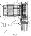
Figure 1 is a schematic top view of a sawing machine for sawing for sawing wooden panels, provided with a plurality of video cameras arranged at or near a respective working station of said sawing machine; -
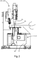
Figure 2 is a side view of one of the two working stations of the sawing machine ofFigure 1 ; -
Figure 3 is a schematic perspective view of one of the two working stations of the sawing machine ofFigure 1 ; -
Figure 4 is a schematic view of a video camera to show that said video camera comprises inside a memory element. - With reference to
Figures 1 to 4 , a machine tool M is described for working pieces P, such as for example panels made of wood, ceramic, plastic, metal, glass, fiberglass. - In the example described, said machine tool M is a sawing machine, and said pieces P are wooden panels.
- Said sawing machine M comprises:
- one or more video cameras VC, each of which is arranged in a respective predetermined position with respect to said sawing machine M and configured to record a video during the working of said pieces by said sawing machine M,
- storage means S for storing the videos of each video camera VC,
- display means D for displaying the videos from each video camera VC and stored in said storage means S.
- As shown in the embodiment that is described, it is preferable that said sawing machine M comprises a logic control unit U, connected to said storage means S and configured to:
- acquire one or more videos from said storage means S,
- detect the operating state of said sawing machine M, in particular one or more data concerning said operating state of said sawing machine M, when said sawing machine is in use.
- Advantageously, in case of a breakdown or malfunction of the sawing machine M, an operator has double information: a first information deriving from the video of one or more video cameras VC, and a second information concerning the operating status of the sawing machine itself.
- From the combination of this information, an operator can understand in detail where the failure or malfunction occurred and the type of failure or malfunction.
- In other words, the information not deducible from the video(s) can be obtained by viewing the data concerning the operating status of the sawing machine M, before the breakdown or malfunction.
- For example, the data associated with the operating status of the sawing machine M can be the following: a data associated with the moving saw carriage/stationary saw carriage, a data associated with the rotating blade/stationary blade, a data associated with the fact that the blade and scoring device are not aligned, a data associated with the presence/absence of the blade, a data associated with the raised pressing device/lowered pressing device, a data associated with the presence of a piece under of the pressing device, a data associated with the presence of a piece on one or more planes of at least one loading station and/or at least one unloading station, a data associated with the presence of a piece on a loading plane, a data associated with the end of the pieces in storage unit, a data associated with the end of the working process on one or more pieces according to a predetermined cutting pattern, a data associated with one or more moving pushers, a data associated with one or more grippers gripping a piece, a data connected to the on/off suction, a data associated with an alarm state of the machine, a data associated with a pause state, a data associated with an operational stop state, a data associated with the machine on/machine off, a data associated with the machine in emergency, a data associated with the position of one or more floors of at least one loading station and/or at least one unloading station, a data associated with the presence of an operator, a data associated with the violation of a security perimeter by an operator.
- In other words, the operating status of the machine can be identified by one or more data indicated above.
- However, it is not necessary to acquire or record data relating to the operating status of the sawing machine M.
- For example, in a not shown variant, it is possible to detect the operating status of this sawing machine from one or more videos by means of a known algorithm, such as a motion detection algorithm, which can be performed by the control logic unit, or from at least one video camera configured to implement this algorithm.
- In particular, said logic control unit U can be configured to acquire said one or more videos from said storage means S as a function of the operating state of the sawing machine M, in particular as a function of said one or more data concerning said operating state.
- In general, as already mentioned, a machine tool M can comprise a plurality of stations connected in series with each other: at least one loading station, at least one unloading station, and at least one working station to perform respective machining on one or more pieces P.
- The panels P to be worked are arranged on a support plane of said at least one loading station, and advance on said support plane along an advancement longitudinal direction (with respect to the support plane) until they reach the working station, by means of a thrust exerted by a plurality of pushers, each of which can comprise a respective gripper for gripping the workpiece.
- The panels worked by the working station of the machine tool M reach a support surface of an unloading station, and are picked up by an operator or by a mechanical arm.
- In the embodiment described, said sawing machine M comprises a loading station LS1 and a working station WS1, arranged at one end of said loading station LS1, as well as a further loading station LS2, connected to said working station WS1, a further working station WS2, arranged at one end of said further loading station LS2 and an unloading station US (in the example described, said unloading station comprises three floors, in particular three air-veiled tops, each one of which is movable in a direction transverse with respect to the advance direction).
- As shown in
Figure 3 , each working station WS1, WS2 is a cutting station that comprises: - a respective pressing device PD, coupled to the base of said machine tool, movable between a first position or lower position, in which the panel is clamped on the support surface of the respective loading station LS1, LS2 at the respective cutting station, and a second or upper position, in which the panel is released by said pressure device PD,
- a respective cutting device GB comprising a first blade B1 for engraving the panel, and a second blade B2 for cutting said panel (as it is known).
- Each pressing device PD can move in a first direction or in a second direction (opposite to said first direction) along an axis vertical with respect to the advancement direction of the panel(s) P on the support plane of the loading station LS1.
- The advancement direction of the panel(s) is indicated by the arrow AP.
- The cutting device GB can move in a first direction or in a second direction (opposite to said first direction) along an axis X, which is transversal to the feed direction AP of the panel(s).
- In the embodiment that is described, said sawing machine M comprises two video cameras VC: a video camera VC arranged at or near said working station WS1, in such a way as to film an area A1, so as to record a video concerning said area A1, and a further video camera VC, arranged at or near said further working station WS2, in such a way as to film a further area A2, so as to record a video concerning said further area A2.
- Each area A1, A2 is indicated in
Figure 1 with a respective plurality of dashed lines. - Although not shown in the Figures, the sawing machine M can comprise further video cameras, without departing from the scope of the invention.
- For example, at least one video camera can be arranged at, or near the loading station LS1, in such a way as to record an area of said loading station LS1 (so as to record a video concerning said area), and/or at least one video camera can be arranged at or near the unloading station LS1, in such a way as to film an area of said unloading station LS1 (so as to record a video concerning said area).
- In the embodiment described, said video cameras VC are configured to video recording continuously.
- However, the control logic unit U can be configured to activate/deactivate one or more video cameras VC in a predetermined time window.
- Said predetermined time window can be chosen on the basis of the operating state of the sawing machine M, in particular on the basis of the data relating to said operating state of said sawing machine.
- Although not shown in the Figures, the sawing machine M can comprise a protection element for each video camera VC.
- Furthermore, although not shown in the Figures, it is preferable that said sawing machine M comprises a respective blower for each video camera VC, so as to remove the dust from each video camera VC.
- With reference to said display means D, said display means D can comprise a display included in a mobile electronic device MP (as in the case of the embodiment that is described) and/or in a multimedia totem connected to said sawing machine M.
- A mobile electronic device means any electronic device, such as a smartphone, tablet, laptop, or similar.
- With reference to said logic control unit U, it can be configured to send at least a portion of said one or more videos to said mobile electronic device MP and/or to said multimedia totem.
- It is preferable that said logic control unit U is configured to send the operating status of said sawing machine M (in particular said one or more data concerning the operating status of the sawing machine M) to said mobile electronic device MP and/or said multimedia totem.
- Although not shown in the Figures, said logic control unit U can be configured to send at least a portion of said one or more videos to a cloud server, and the latter can be configured to send said at least one portion of said one or more videos to said mobile electronic device MP and/or to said multimedia totem.
- Furthermore, said logic control unit U can be configured to send the operating status of said sawing machine M to said cloud server, in particular, said one or more data concerning the operating status of said sawing machine, regardless of the sending of said portion of video to said mobile electronic device MP and/or to said multimedia totem.
- With reference to said storage means S, in the embodiment that is described, as shown in
Figure 4 , said storage means S comprises a respective memory element, arranged inside each video camera VC. - However, although not shown in the Figures, said storage means S can comprise a single memory element for said one or more video cameras VC, arranged outside each video camera VC, for example in a cloud server.
- Said one or more video cameras can be infrared cameras.
- Alternatively, or in combination with infrared cameras, said sawing machine M can be provided with lighting means, for illuminating one or more shaded areas that fall within a field of view of the one or more video cameras VC.
- It is preferable that said lighting means comprise one or more LEDs.
- Advantageously, through said infrared cameras and/or said illumination means, it is possible to obtain the recording of one or more videos in different lighting conditions, up to complete darkness.
- Advantageously, by means of the machine tool object of the present invention, it is possible to facilitate the task of an operator who wishes to identify where a fault or malfunction has occurred and to understand the type of fault or malfunction.
- In this way, it is possible to reduce the intervention time by the operator himself.
- A further advantage is given by the operator's ability to watch the content of the video captured through one or more video cameras, and read the data regarding the operating status of the machine tool up to the moment of failure or malfunction.
- The present invention has been described for illustrative but not limitative purposes, according to its preferred embodiments, but it is to be understood that modifications and/or changes can be introduced by those skilled in the art without departing from the relevant scope as defined in the enclosed claims.
Claims (15)
- Machine tool (M) for working one or more pieces (P), said machine tool (M) comprising:- one or more video cameras (VC), each of which is arranged in a respective predetermined position with respect to said machine tool (M) and configured to record a video during the working of said pieces (P) by said machine tool (M),- storage means (S) for storing the videos of each video camera (VC),- displaying means (D) for displaying the videos of each video camera (VC), stored in said storage means (S).
- Machine tool (M) according to the previous claim, characterized in that said machine tool (M) comprises a logic control unit (U), connected to said storage means (S) and configured to:- acquire one or more videos from said storage means (S),- detect the operating state of said machine tool (M), in particular one or more data concerning said operating state of said machine tool (M), when said machine tool (M) is in use.
- Machine tool (M) according to the previous claim, characterized in that said logic control unit (U) is configured to acquire said one or more videos from said storage means (S) on the basis of said operating state of said machine tool (M), in particular on the basis of said one or more data concerning said operating state of said machine tool (M).
- Machine tool (M) according to the previous claim, characterized in that said logic control unit (U) is configured to activate/deactivate one or more video cameras (VC) in a predetermined time window.
- Machine tool (M) according to any one of the previous claims, characterized
in that
said machine tool (M) comprises at least one working station (WS1,WS2) and at least one video camera (VC), the latter arranged in correspondence or in proximity of said at least one working station (WS1,WS2) so as to record a video concerning an area (A1,A2) of said working station (WS1,WS2),
and/or
in that
said machine tool (M) comprises at least one loading station (LS1,LS2) and at least one video camera (VC), the latter arranged in correspondence or in proximity of said at least one loading station (LS1 ,LS2) so as to record a video concerning an area of said loading station (LS1, LS2),
and/or
in that
said machine tool (M) comprises at least one unloading station (US) and at least one video camera (VC), the latter arranged in correspondence or proximity of said unloading station (US) so as to record a video concerning an area of said unloading station (US). - Machine tool (M) according to any one of the previous claims, characterized in that said machine tool (M) comprises a respective blower for each video camera (VC), so as to remove the dust from each video camera (VC).
- Machine tool (M) according to any one of the previous claims, characterized in that said display means (D) comprise a display included in a mobile electronic device (MP) and/or in a multimedia totem connected to said machine tool (M).
- Machine tool (M) according to the previous claim, characterized in that said logic control unit (U) is configured to send at least a portion of said one or more videos to said mobile electronic device (MP) and/or to said multimedia totem.
- Machine tool (M) according to the previous claim, characterized in that said logic control unit (U) is configured to send said operating state of said machine tool (M) to said mobile electronic device (MP) and/or to said multimedia totem, in particular said one or more data concerning said operating state of said machine tool (M).
- Machine tool (M) according to any one of the previous claims, characterized in that
said logic control unit (U) is configured to send at least a portion of said one or more videos to a cloud server,
in that
said cloud server is configured to send said at least a portion of said one or more videos to said mobile electronic device (MP) and/or said multimedia totem. - Machine tool (M) according to the previous claim, characterized in that said logic control unit (U) is configured to send said operating state of said machine tool (M) to said cloud server, in particular said one or more data concerning said operating state of said machine tool (M).
- Machine tool (M) according to any one of claims 1-11, characterized in that said storage means (S) comprise a respective memory element, arranged inside each video camera (VC).
- Machine tool (M) according to any one of claims 1-11, characterized in that said storage means (S) comprise a memory element for said one or more video cameras (VC), arranged outside each camera (VC), in particular in a cloud server.
- Machine tool (M) according to any one of claims 1-13, characterized in that said one or more video cameras is/are infrared camera/s.
- Machine tool (M) according to any one of the previous claims, characterized in that said machine tool (M) is provided with lighting means for illuminating one or more shaded areas that fall within a visual field of one or more video cameras (VC); said lighting means preferably comprising one or more LEDs.
Applications Claiming Priority (1)
| Application Number | Priority Date | Filing Date | Title |
|---|---|---|---|
| IT102020000003230A IT202000003230A1 (en) | 2020-02-18 | 2020-02-18 | Machine tool for machining pieces configured to control one or more processing stages |
Publications (2)
| Publication Number | Publication Date |
|---|---|
| EP3868514A1 true EP3868514A1 (en) | 2021-08-25 |
| EP3868514B1 EP3868514B1 (en) | 2024-06-26 |
Family
ID=70480705
Family Applications (1)
| Application Number | Title | Priority Date | Filing Date |
|---|---|---|---|
| EP21157087.4A Active EP3868514B1 (en) | 2020-02-18 | 2021-02-15 | Machine tool for working pieces configured to control one or more working steps |
Country Status (2)
| Country | Link |
|---|---|
| EP (1) | EP3868514B1 (en) |
| IT (1) | IT202000003230A1 (en) |
Citations (8)
| Publication number | Priority date | Publication date | Assignee | Title |
|---|---|---|---|---|
| US20060177119A1 (en) * | 2002-10-25 | 2006-08-10 | Mcpheely Bernard M | Digital diagnosti video system for manufacturing and industrial process |
| EP1932618A1 (en) * | 2006-12-11 | 2008-06-18 | Index-Werke Gmbh & Co. Kg Hahn & Tessky | Work machine |
| DE202014102322U1 (en) * | 2014-05-16 | 2014-08-22 | Klingelnberg Ag | Device for machining a workpiece |
| US20180099369A1 (en) * | 2016-10-10 | 2018-04-12 | Red Wing Shoe Company, Inc. | Cutting tool with auto-stop |
| EP3348350A1 (en) * | 2017-01-16 | 2018-07-18 | Nakamura-Tome Precision Industry Co., Ltd | Machine tool with camera |
| CN207629741U (en) * | 2017-12-18 | 2018-07-20 | 安徽省安达兴智能装备有限公司 | Closed remote control vertical machining center |
| WO2019008855A1 (en) * | 2017-07-04 | 2019-01-10 | コマツ産機株式会社 | Machine system and control method |
| US20190258863A1 (en) * | 2016-04-19 | 2019-08-22 | Rockwell Automation Technologies, Inc. | Analyzing video streams in an industrial environment to identify potential problems and select recipients for a display of video streams related to the potential problems |
-
2020
- 2020-02-18 IT IT102020000003230A patent/IT202000003230A1/en unknown
-
2021
- 2021-02-15 EP EP21157087.4A patent/EP3868514B1/en active Active
Patent Citations (8)
| Publication number | Priority date | Publication date | Assignee | Title |
|---|---|---|---|---|
| US20060177119A1 (en) * | 2002-10-25 | 2006-08-10 | Mcpheely Bernard M | Digital diagnosti video system for manufacturing and industrial process |
| EP1932618A1 (en) * | 2006-12-11 | 2008-06-18 | Index-Werke Gmbh & Co. Kg Hahn & Tessky | Work machine |
| DE202014102322U1 (en) * | 2014-05-16 | 2014-08-22 | Klingelnberg Ag | Device for machining a workpiece |
| US20190258863A1 (en) * | 2016-04-19 | 2019-08-22 | Rockwell Automation Technologies, Inc. | Analyzing video streams in an industrial environment to identify potential problems and select recipients for a display of video streams related to the potential problems |
| US20180099369A1 (en) * | 2016-10-10 | 2018-04-12 | Red Wing Shoe Company, Inc. | Cutting tool with auto-stop |
| EP3348350A1 (en) * | 2017-01-16 | 2018-07-18 | Nakamura-Tome Precision Industry Co., Ltd | Machine tool with camera |
| WO2019008855A1 (en) * | 2017-07-04 | 2019-01-10 | コマツ産機株式会社 | Machine system and control method |
| CN207629741U (en) * | 2017-12-18 | 2018-07-20 | 安徽省安达兴智能装备有限公司 | Closed remote control vertical machining center |
Also Published As
| Publication number | Publication date |
|---|---|
| EP3868514B1 (en) | 2024-06-26 |
| IT202000003230A1 (en) | 2021-08-18 |
Similar Documents
| Publication | Publication Date | Title |
|---|---|---|
| ES2367958T3 (en) | MACHINING MACHINE WITH SECURITY SCANNER. | |
| CN106470797B (en) | Method for operating board processing apparatus, and board processing apparatus | |
| CN109843503B (en) | Conveying equipment, control device thereof and loading and unloading method of material processing unit | |
| EP4032671B1 (en) | Method for picking up a panel from the exit station of a machine for working panels made of wood and the like and machine thereof | |
| US10247636B2 (en) | Sheet metal processing machines having a chip suctioning device and methods for detecting a malfunction in the chip suctioning device | |
| CN106102975A (en) | A kind of method for running plate processing unit (plant) | |
| CN107985950B (en) | A loading attachment for separating equipment of useless book | |
| JP7220035B2 (en) | band saw | |
| CN112024915A (en) | Disc part processing production line | |
| CN112025714A (en) | Workpiece grabbing method and device and robot equipment | |
| EP3868514B1 (en) | Machine tool for working pieces configured to control one or more working steps | |
| US20240383010A1 (en) | Sorting method for an automatic sorting process, and sorting device | |
| CN113213034A (en) | Storage bin applied to intelligent storage system and operation method thereof | |
| US10500892B2 (en) | Method and apparatus with rotating tool changer for automated multiple sides workpiece machining | |
| CN109747196B (en) | Pressure device | |
| WO1995027597A1 (en) | Multidirectional cutting tool in a punch press environment | |
| CN115707566A (en) | Light wood defect detecting and removing line | |
| CN105489087B (en) | A production line for processing learning cards for the blind | |
| CN112384333A (en) | Working equipment with under-table manipulator | |
| KR840006156A (en) | Combined shear and punch press | |
| CN113276128A (en) | Flexible automatic workstation for discriminating product processing raw materials and discriminating system thereof | |
| US20140148940A1 (en) | System for Remotely Deactivating the Operation of a Machine | |
| EP3939728B1 (en) | Machine for sawing panels provided with an improved exit station | |
| JPH03219907A (en) | Method and apparatus for working workpiece in wood working equipment | |
| CN212551103U (en) | Plate shearing machine with width detection function |
Legal Events
| Date | Code | Title | Description |
|---|---|---|---|
| PUAI | Public reference made under article 153(3) epc to a published international application that has entered the european phase |
Free format text: ORIGINAL CODE: 0009012 |
|
| STAA | Information on the status of an ep patent application or granted ep patent |
Free format text: STATUS: THE APPLICATION HAS BEEN PUBLISHED |
|
| AK | Designated contracting states |
Kind code of ref document: A1 Designated state(s): AL AT BE BG CH CY CZ DE DK EE ES FI FR GB GR HR HU IE IS IT LI LT LU LV MC MK MT NL NO PL PT RO RS SE SI SK SM TR |
|
| STAA | Information on the status of an ep patent application or granted ep patent |
Free format text: STATUS: REQUEST FOR EXAMINATION WAS MADE |
|
| 17P | Request for examination filed |
Effective date: 20220111 |
|
| RBV | Designated contracting states (corrected) |
Designated state(s): AL AT BE BG CH CY CZ DE DK EE ES FI FR GB GR HR HU IE IS IT LI LT LU LV MC MK MT NL NO PL PT RO RS SE SI SK SM TR |
|
| P01 | Opt-out of the competence of the unified patent court (upc) registered |
Effective date: 20230518 |
|
| GRAP | Despatch of communication of intention to grant a patent |
Free format text: ORIGINAL CODE: EPIDOSNIGR1 |
|
| STAA | Information on the status of an ep patent application or granted ep patent |
Free format text: STATUS: GRANT OF PATENT IS INTENDED |
|
| INTG | Intention to grant announced |
Effective date: 20240209 |
|
| GRAS | Grant fee paid |
Free format text: ORIGINAL CODE: EPIDOSNIGR3 |
|
| GRAA | (expected) grant |
Free format text: ORIGINAL CODE: 0009210 |
|
| STAA | Information on the status of an ep patent application or granted ep patent |
Free format text: STATUS: THE PATENT HAS BEEN GRANTED |
|
| AK | Designated contracting states |
Kind code of ref document: B1 Designated state(s): AL AT BE BG CH CY CZ DE DK EE ES FI FR GB GR HR HU IE IS IT LI LT LU LV MC MK MT NL NO PL PT RO RS SE SI SK SM TR |
|
| REG | Reference to a national code |
Ref country code: GB Ref legal event code: FG4D |
|
| REG | Reference to a national code |
Ref country code: CH Ref legal event code: EP |
|
| REG | Reference to a national code |
Ref country code: DE Ref legal event code: R096 Ref document number: 602021014691 Country of ref document: DE |
|
| PG25 | Lapsed in a contracting state [announced via postgrant information from national office to epo] |
Ref country code: BG Free format text: LAPSE BECAUSE OF FAILURE TO SUBMIT A TRANSLATION OF THE DESCRIPTION OR TO PAY THE FEE WITHIN THE PRESCRIBED TIME-LIMIT Effective date: 20240626 |
|
| PG25 | Lapsed in a contracting state [announced via postgrant information from national office to epo] |
Ref country code: HR Free format text: LAPSE BECAUSE OF FAILURE TO SUBMIT A TRANSLATION OF THE DESCRIPTION OR TO PAY THE FEE WITHIN THE PRESCRIBED TIME-LIMIT Effective date: 20240626 Ref country code: FI Free format text: LAPSE BECAUSE OF FAILURE TO SUBMIT A TRANSLATION OF THE DESCRIPTION OR TO PAY THE FEE WITHIN THE PRESCRIBED TIME-LIMIT Effective date: 20240626 |
|
| REG | Reference to a national code |
Ref country code: LT Ref legal event code: MG9D |
|
| PG25 | Lapsed in a contracting state [announced via postgrant information from national office to epo] |
Ref country code: GR Free format text: LAPSE BECAUSE OF FAILURE TO SUBMIT A TRANSLATION OF THE DESCRIPTION OR TO PAY THE FEE WITHIN THE PRESCRIBED TIME-LIMIT Effective date: 20240927 |
|
| PG25 | Lapsed in a contracting state [announced via postgrant information from national office to epo] |
Ref country code: LV Free format text: LAPSE BECAUSE OF FAILURE TO SUBMIT A TRANSLATION OF THE DESCRIPTION OR TO PAY THE FEE WITHIN THE PRESCRIBED TIME-LIMIT Effective date: 20240626 |
|
| REG | Reference to a national code |
Ref country code: NL Ref legal event code: MP Effective date: 20240626 |
|
| PG25 | Lapsed in a contracting state [announced via postgrant information from national office to epo] |
Ref country code: NO Free format text: LAPSE BECAUSE OF FAILURE TO SUBMIT A TRANSLATION OF THE DESCRIPTION OR TO PAY THE FEE WITHIN THE PRESCRIBED TIME-LIMIT Effective date: 20240926 Ref country code: LV Free format text: LAPSE BECAUSE OF FAILURE TO SUBMIT A TRANSLATION OF THE DESCRIPTION OR TO PAY THE FEE WITHIN THE PRESCRIBED TIME-LIMIT Effective date: 20240626 Ref country code: HR Free format text: LAPSE BECAUSE OF FAILURE TO SUBMIT A TRANSLATION OF THE DESCRIPTION OR TO PAY THE FEE WITHIN THE PRESCRIBED TIME-LIMIT Effective date: 20240626 Ref country code: GR Free format text: LAPSE BECAUSE OF FAILURE TO SUBMIT A TRANSLATION OF THE DESCRIPTION OR TO PAY THE FEE WITHIN THE PRESCRIBED TIME-LIMIT Effective date: 20240927 Ref country code: FI Free format text: LAPSE BECAUSE OF FAILURE TO SUBMIT A TRANSLATION OF THE DESCRIPTION OR TO PAY THE FEE WITHIN THE PRESCRIBED TIME-LIMIT Effective date: 20240626 Ref country code: BG Free format text: LAPSE BECAUSE OF FAILURE TO SUBMIT A TRANSLATION OF THE DESCRIPTION OR TO PAY THE FEE WITHIN THE PRESCRIBED TIME-LIMIT Effective date: 20240626 Ref country code: RS Free format text: LAPSE BECAUSE OF FAILURE TO SUBMIT A TRANSLATION OF THE DESCRIPTION OR TO PAY THE FEE WITHIN THE PRESCRIBED TIME-LIMIT Effective date: 20240926 |
|
| PG25 | Lapsed in a contracting state [announced via postgrant information from national office to epo] |
Ref country code: NL Free format text: LAPSE BECAUSE OF FAILURE TO SUBMIT A TRANSLATION OF THE DESCRIPTION OR TO PAY THE FEE WITHIN THE PRESCRIBED TIME-LIMIT Effective date: 20240626 |
|
| PG25 | Lapsed in a contracting state [announced via postgrant information from national office to epo] |
Ref country code: NL Free format text: LAPSE BECAUSE OF FAILURE TO SUBMIT A TRANSLATION OF THE DESCRIPTION OR TO PAY THE FEE WITHIN THE PRESCRIBED TIME-LIMIT Effective date: 20240626 |
|
| PG25 | Lapsed in a contracting state [announced via postgrant information from national office to epo] |
Ref country code: PT Free format text: LAPSE BECAUSE OF FAILURE TO SUBMIT A TRANSLATION OF THE DESCRIPTION OR TO PAY THE FEE WITHIN THE PRESCRIBED TIME-LIMIT Effective date: 20241028 |
|
| PG25 | Lapsed in a contracting state [announced via postgrant information from national office to epo] |
Ref country code: PT Free format text: LAPSE BECAUSE OF FAILURE TO SUBMIT A TRANSLATION OF THE DESCRIPTION OR TO PAY THE FEE WITHIN THE PRESCRIBED TIME-LIMIT Effective date: 20241028 |
|
| PG25 | Lapsed in a contracting state [announced via postgrant information from national office to epo] |
Ref country code: PL Free format text: LAPSE BECAUSE OF FAILURE TO SUBMIT A TRANSLATION OF THE DESCRIPTION OR TO PAY THE FEE WITHIN THE PRESCRIBED TIME-LIMIT Effective date: 20240626 |
|
| PG25 | Lapsed in a contracting state [announced via postgrant information from national office to epo] |
Ref country code: EE Free format text: LAPSE BECAUSE OF FAILURE TO SUBMIT A TRANSLATION OF THE DESCRIPTION OR TO PAY THE FEE WITHIN THE PRESCRIBED TIME-LIMIT Effective date: 20240626 |
|
| PG25 | Lapsed in a contracting state [announced via postgrant information from national office to epo] |
Ref country code: IS Free format text: LAPSE BECAUSE OF FAILURE TO SUBMIT A TRANSLATION OF THE DESCRIPTION OR TO PAY THE FEE WITHIN THE PRESCRIBED TIME-LIMIT Effective date: 20241026 |
|
| PG25 | Lapsed in a contracting state [announced via postgrant information from national office to epo] |
Ref country code: CZ Free format text: LAPSE BECAUSE OF FAILURE TO SUBMIT A TRANSLATION OF THE DESCRIPTION OR TO PAY THE FEE WITHIN THE PRESCRIBED TIME-LIMIT Effective date: 20240626 |
|
| PG25 | Lapsed in a contracting state [announced via postgrant information from national office to epo] |
Ref country code: RO Free format text: LAPSE BECAUSE OF FAILURE TO SUBMIT A TRANSLATION OF THE DESCRIPTION OR TO PAY THE FEE WITHIN THE PRESCRIBED TIME-LIMIT Effective date: 20240626 Ref country code: SK Free format text: LAPSE BECAUSE OF FAILURE TO SUBMIT A TRANSLATION OF THE DESCRIPTION OR TO PAY THE FEE WITHIN THE PRESCRIBED TIME-LIMIT Effective date: 20240626 |
|
| PG25 | Lapsed in a contracting state [announced via postgrant information from national office to epo] |
Ref country code: SM Free format text: LAPSE BECAUSE OF FAILURE TO SUBMIT A TRANSLATION OF THE DESCRIPTION OR TO PAY THE FEE WITHIN THE PRESCRIBED TIME-LIMIT Effective date: 20240626 Ref country code: ES Free format text: LAPSE BECAUSE OF FAILURE TO SUBMIT A TRANSLATION OF THE DESCRIPTION OR TO PAY THE FEE WITHIN THE PRESCRIBED TIME-LIMIT Effective date: 20240626 |
|
| PG25 | Lapsed in a contracting state [announced via postgrant information from national office to epo] |
Ref country code: SM Free format text: LAPSE BECAUSE OF FAILURE TO SUBMIT A TRANSLATION OF THE DESCRIPTION OR TO PAY THE FEE WITHIN THE PRESCRIBED TIME-LIMIT Effective date: 20240626 Ref country code: SK Free format text: LAPSE BECAUSE OF FAILURE TO SUBMIT A TRANSLATION OF THE DESCRIPTION OR TO PAY THE FEE WITHIN THE PRESCRIBED TIME-LIMIT Effective date: 20240626 Ref country code: RO Free format text: LAPSE BECAUSE OF FAILURE TO SUBMIT A TRANSLATION OF THE DESCRIPTION OR TO PAY THE FEE WITHIN THE PRESCRIBED TIME-LIMIT Effective date: 20240626 Ref country code: PL Free format text: LAPSE BECAUSE OF FAILURE TO SUBMIT A TRANSLATION OF THE DESCRIPTION OR TO PAY THE FEE WITHIN THE PRESCRIBED TIME-LIMIT Effective date: 20240626 Ref country code: IS Free format text: LAPSE BECAUSE OF FAILURE TO SUBMIT A TRANSLATION OF THE DESCRIPTION OR TO PAY THE FEE WITHIN THE PRESCRIBED TIME-LIMIT Effective date: 20241026 Ref country code: ES Free format text: LAPSE BECAUSE OF FAILURE TO SUBMIT A TRANSLATION OF THE DESCRIPTION OR TO PAY THE FEE WITHIN THE PRESCRIBED TIME-LIMIT Effective date: 20240626 Ref country code: EE Free format text: LAPSE BECAUSE OF FAILURE TO SUBMIT A TRANSLATION OF THE DESCRIPTION OR TO PAY THE FEE WITHIN THE PRESCRIBED TIME-LIMIT Effective date: 20240626 Ref country code: CZ Free format text: LAPSE BECAUSE OF FAILURE TO SUBMIT A TRANSLATION OF THE DESCRIPTION OR TO PAY THE FEE WITHIN THE PRESCRIBED TIME-LIMIT Effective date: 20240626 |
|
| REG | Reference to a national code |
Ref country code: DE Ref legal event code: R097 Ref document number: 602021014691 Country of ref document: DE |
|
| PG25 | Lapsed in a contracting state [announced via postgrant information from national office to epo] |
Ref country code: DK Free format text: LAPSE BECAUSE OF FAILURE TO SUBMIT A TRANSLATION OF THE DESCRIPTION OR TO PAY THE FEE WITHIN THE PRESCRIBED TIME-LIMIT Effective date: 20240626 |
|
| PLBE | No opposition filed within time limit |
Free format text: ORIGINAL CODE: 0009261 |
|
| STAA | Information on the status of an ep patent application or granted ep patent |
Free format text: STATUS: NO OPPOSITION FILED WITHIN TIME LIMIT |
|
| 26N | No opposition filed |
Effective date: 20250327 |
|
| PG25 | Lapsed in a contracting state [announced via postgrant information from national office to epo] |
Ref country code: SE Free format text: LAPSE BECAUSE OF FAILURE TO SUBMIT A TRANSLATION OF THE DESCRIPTION OR TO PAY THE FEE WITHIN THE PRESCRIBED TIME-LIMIT Effective date: 20240626 |
|
| PG25 | Lapsed in a contracting state [announced via postgrant information from national office to epo] |
Ref country code: MC Free format text: LAPSE BECAUSE OF FAILURE TO SUBMIT A TRANSLATION OF THE DESCRIPTION OR TO PAY THE FEE WITHIN THE PRESCRIBED TIME-LIMIT Effective date: 20240626 |
|
| REG | Reference to a national code |
Ref country code: CH Ref legal event code: PL |
|
| PG25 | Lapsed in a contracting state [announced via postgrant information from national office to epo] |
Ref country code: LU Free format text: LAPSE BECAUSE OF NON-PAYMENT OF DUE FEES Effective date: 20250215 |
|
| REG | Reference to a national code |
Ref country code: AT Ref legal event code: UEP Ref document number: 1697318 Country of ref document: AT Kind code of ref document: T Effective date: 20240626 |
|
| PG25 | Lapsed in a contracting state [announced via postgrant information from national office to epo] |
Ref country code: CH Free format text: LAPSE BECAUSE OF NON-PAYMENT OF DUE FEES Effective date: 20250228 |
|
| GBPC | Gb: european patent ceased through non-payment of renewal fee |
Effective date: 20250215 |
|
| REG | Reference to a national code |
Ref country code: BE Ref legal event code: MM Effective date: 20250228 |
|
| PG25 | Lapsed in a contracting state [announced via postgrant information from national office to epo] |
Ref country code: GB Free format text: LAPSE BECAUSE OF NON-PAYMENT OF DUE FEES Effective date: 20250215 |
|
| PG25 | Lapsed in a contracting state [announced via postgrant information from national office to epo] |
Ref country code: FR Free format text: LAPSE BECAUSE OF NON-PAYMENT OF DUE FEES Effective date: 20250228 |
|
| PG25 | Lapsed in a contracting state [announced via postgrant information from national office to epo] |
Ref country code: BE Free format text: LAPSE BECAUSE OF NON-PAYMENT OF DUE FEES Effective date: 20250228 |
|
| PG25 | Lapsed in a contracting state [announced via postgrant information from national office to epo] |
Ref country code: IE Free format text: LAPSE BECAUSE OF NON-PAYMENT OF DUE FEES Effective date: 20250215 |
|
| PGFP | Annual fee paid to national office [announced via postgrant information from national office to epo] |
Ref country code: DE Payment date: 20260217 Year of fee payment: 6 |
|
| PGFP | Annual fee paid to national office [announced via postgrant information from national office to epo] |
Ref country code: AT Payment date: 20260216 Year of fee payment: 6 |
|
| PGFP | Annual fee paid to national office [announced via postgrant information from national office to epo] |
Ref country code: IT Payment date: 20260113 Year of fee payment: 6 |