EP3866455A1 - Device and method for capturing images or video - Google Patents
Device and method for capturing images or video Download PDFInfo
- Publication number
- EP3866455A1 EP3866455A1 EP20305142.0A EP20305142A EP3866455A1 EP 3866455 A1 EP3866455 A1 EP 3866455A1 EP 20305142 A EP20305142 A EP 20305142A EP 3866455 A1 EP3866455 A1 EP 3866455A1
- Authority
- EP
- European Patent Office
- Prior art keywords
- image data
- sensor
- rectangular
- hardware processor
- data
- Prior art date
- Legal status (The legal status is an assumption and is not a legal conclusion. Google has not performed a legal analysis and makes no representation as to the accuracy of the status listed.)
- Withdrawn
Links
Images


Classifications
-
- H—ELECTRICITY
- H04—ELECTRIC COMMUNICATION TECHNIQUE
- H04N—PICTORIAL COMMUNICATION, e.g. TELEVISION
- H04N23/00—Cameras or camera modules comprising electronic image sensors; Control thereof
- H04N23/45—Cameras or camera modules comprising electronic image sensors; Control thereof for generating image signals from two or more image sensors being of different type or operating in different modes, e.g. with a CMOS sensor for moving images in combination with a charge-coupled device [CCD] for still images
-
- H—ELECTRICITY
- H04—ELECTRIC COMMUNICATION TECHNIQUE
- H04N—PICTORIAL COMMUNICATION, e.g. TELEVISION
- H04N23/00—Cameras or camera modules comprising electronic image sensors; Control thereof
- H04N23/95—Computational photography systems, e.g. light-field imaging systems
- H04N23/951—Computational photography systems, e.g. light-field imaging systems by using two or more images to influence resolution, frame rate or aspect ratio
-
- H—ELECTRICITY
- H04—ELECTRIC COMMUNICATION TECHNIQUE
- H04N—PICTORIAL COMMUNICATION, e.g. TELEVISION
- H04N5/00—Details of television systems
- H04N5/222—Studio circuitry; Studio devices; Studio equipment
- H04N5/262—Studio circuits, e.g. for mixing, switching-over, change of character of image, other special effects ; Cameras specially adapted for the electronic generation of special effects
- H04N5/2628—Alteration of picture size, shape, position or orientation, e.g. zooming, rotation, rolling, perspective, translation
Definitions
- the present disclosure relates generally to digital photography and in particular to photography using handheld devices such as smartphones and tablets.
- a photo in portrait format is not suited for display on a television or other landscape-based display, while, conversely, a photo in landscape format is ill-suited for use as wallpaper on the smartphone and for display on portrait-based displays.
- a suitable mode e.g. portrait or landscape
- the present principles are directed to a device comprising at least one first sensor for capturing first image data, the at least one first sensor being rectangular and directed in a direction in relation to the device, at least one second sensor for capturing second image data, the at least one second sensor being rectangular and directed in the direction and further arranged at least essentially orthogonal to the at least one first rectangular sensor, and at least one hardware processor configured to cause the at least one first sensor and the at least one second sensor to capture, respectively, the first image data and the second image data at least substantially simultaneously.
- the present principles are directed to a method comprising capturing at least substantially simultaneously first image data by at least one first sensor of a device and second image data by at least one second sensor of the device, the at least one first sensor being rectangular and directed in a direction in relation to the device, and the at least one second sensor being rectangular and directed in the direction and further arranged at least essentially orthogonal to the at least one first rectangular sensor.
- the present principles are directed to a computer program product which is stored on a non-transitory computer readable medium and includes program code instructions executable by a processor for implementing the steps of a method according to any embodiment of the second aspect.
- Figure 1 illustrates a device 100 according to an embodiment of the present principles.
- the device 100 will be described as a smartphone, but it will be understood that the device 100 can be implemented as other types of devices, such as a tablet.
- images a.k.a. pictures
- this can be extended to include video, which in practice is a set of images.
- the smartphone 100 includes at least one user interface 110 configured to receive input, such as instructions and selections, from a user and to provide output to the user.
- Any suitable user interface can be used, including for example a microphone, a speaker, a haptic actuator, buttons, a keyboard, and a touchscreen.
- the smartphone 100 further includes at least one hardware processor 120 (“processor") configured to, among other things, control the smartphone 100, process captured images, and execute program code instructions to perform at least one method of the present principles.
- processor hardware processor
- the smartphone 100 also includes memory 130 configured to store the program code instructions, execution parameters, image data, and so on.
- the smartphone 100 further includes a display 140 configured to output visual information such as images, possibly captured by the smartphone 100.
- the display 140 which can be a touchscreen, is part of the user interface 110, but is described separately for emphasis.
- the smartphone 100 further includes at least one first rectangular sensor (“first sensor”) 150 and at least one second rectangular sensor (“second sensor”) 160 configured to capture images.
- the first sensor 150 and the second sensor can have the same aspect ratios (e.g. 4/3 or 16/9), but are oriented to face in the same direction (such as directly outward from the back of the smartphone) and respectively orthogonal or at least essentially orthogonal. Put another way, one sensor can be oriented to capture portraits while the other sensor, possibly otherwise with the same characteristics as the first, is oriented to capture landscapes.
- the smartphone 100 further includes an angle measuring unit 170 configured to measure the roll angle, i.e. the inclination of the smartphone in relation to the horizon.
- the smartphone 100 can include a plurality of first sensors 150 and a plurality of second sensors 160, preferably but not necessarily the same number, oriented to face the same direction.
- different sensors can have different properties in order to make it possible to provide for example bokeh effects, wide angle capacity, telephoto lens capacity, or improved fine details.
- a non-transitory computer readable medium 180 stores program code instructions that, when executed by a processor (e.g. processor 120), implement the steps of a method according to at least one embodiment of the present principles.
- a smartphone will include further features such as a power source and radio interfaces; only features related to the present principles are discussed for reasons of brevity and clarity.
- the processor 120 When taking a picture, for example in response to user instructions, the processor 120 will cause both the first sensor 150 and the second sensor 160 to take a picture at the same time or at least substantially the same time.
- the resulting first picture and second picture can be processed before storage, for example in memory 130, or transmission to another device.
- the first picture and the second picture can be stored in a single file, for example based on the Extensible Device Metadata (XDM) file format that enables storage of image data from a plurality of cameras (sensors) in a single file.
- XDM Extensible Device Metadata
- conventional use of the XDM format appears to require the same pose and same aspect ratio for the images.
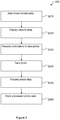
- Figure 2 illustrates a method 200 of an embodiment of the present principles.
- the method 200 can be performed by a device 100 such as the smartphone in Figure 1 .
- step S210 the device 100 starts its photo application enabling photo functionality. This can for example be done in response to user instructions (e.g. via user interface 110 in Figure 1 ), in response to execution of software code or in response to instructions received from an external device.
- step S220 the device 100 displays a capture zone on its display.
- the capture zone indicates at least essentially what can be captured by the device's first and second sensors. The skilled person will appreciate that this enables the user to aim the device before taking a picture, in order to frame the picture.
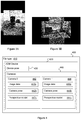
- Figures 3A and 3B illustrate examples of capture zones on a display of a device according to embodiments of the present principles.
- Figure 3A illustrates a first example of a capture zone with a 4/3 aspect ratio displayed on a vertically oriented smartphone.
- Figure 3B illustrates a second example of a capture zone with a 16/9 aspect ratio displayed on a horizontally oriented smartphone.
- the capture zone is cross-shaped. Indeed, the capture zone displays what is "seen" by the first sensor and by the second sensor.
- the input from the first sensor and the second sensor are processed (as will be explained hereafter) with the goal of providing a seamless stitching of the inputs.
- the capture zone shows the input from one of the sensors and the "missing parts" from the input of the other sensor.
- step S230 the device 100 obtains instructions to take a picture. As in step S210, this can for example be user instructions.
- step S240 in response to the instructions, the device 100 captures the input from the first and the second sensor separately.
- step S250 the device 100 processes the captured input from the first and second sensors. This processing will be further described hereafter.
- step S260 the device 100 stores the captured photo, i.e. the processed input.
- the captured photo can be stored in memory of the device or output to a further device for storage.
- the captured input can be stored in a single file, e.g. using the XDM file format, input from each sensor being associated with a different "camera”.
- the processing can include respectively associating the captured input from the sensors with sensor pose information, for example vertical or horizontal.
- Figure 4 illustrates an example of a file storing a photo captured using the method illustrated in Figure 2 .
- the file format is XDM.
- the XDM file 400 includes an indication of file type 410, such as JPEG and GIF, XDM device information 420 including device pose 430 and camera information 440.
- the camera information 440 can include information relating to a first camera 442 and information relating to a second camera 444.
- the information relating to a camera 442, 444 can each correspond to a sensor, e.g. Camera 0 can correspond to the first sensor 150 and Camera 1 to the second sensor 160, or vice versa.
- Each information relating to a camera 442, 444 can include processed image data 442a, 444a from the corresponding sensor, information about the camera pose (i.e. sensor pose) 442b, 444b and a perspective model 442c, 444c, i.e. intrinsic parameters of a camera such as for example focal length, principal point for the optical axis, skew, and lens distortion.
- Figures 5A and 5B respectively illustrate examples of displayed processed data corresponding to the sensors.
- Figure 5A shows a landscape image captured by one sensor and
- Figure 5B a portrait image captured by the other sensor.
- the device When displaying the stored photo, the device can show a combined image with data from both sensors combined in any suitable way, only the landscape image or only the portrait image. What the device displays can be preset or selected by a user. The device can display the combined image and then, in response to user instructions, display, store or output one of the two images.
- the captured data is processed to reduce the size of the resulting file. It is noted that this processing also can be used to provide the seamless stitching mentioned with reference to step S220.
- captured image data from one sensor is rectified to the referential of the other sensor, resized and then cropped to keep only the additional parts of the captured image data.
- Figure 6 illustrates a method for processing captured data according to the further embodiment.
- the first camera, Camera 0 is the one that took the landscape picture and the second camera, Camera 1, took the portrait picture, but it can be the other way around.
- step S610 a processor obtains the captured data from Camera 1, the pose and perspective model from Camera 1 and the pose and perspective model from Camera 0.
- step S620 the processor rectifies the captured image data from Camera 1 to the referential of Camera 0, which results in rectified image data.
- This is a well-known procedure that will not be further described herein as it has been described in for example Z. Zhang, "A Flexible New Technique for Camera Calibration," in IEEE Transactions on Pattern Analysis and Machine Intelligence, vol. 22, no. 11, pp. 1330-1334, Nov. 2000 . and in J.-Y. Bouguet, Camera Calibration Toolbox for Matlab, http://www.vision.caltech.edu/bouguetj/calib_doc/index.html .
- step S630 the processor resizes the rectified image data to match the size of the captured image data from Camera 0, which results in resized image data. This, too, is a well-known procedure.
- step S640 the processor removes the redundant parts of the resized image data, which results in reduced image data.
- the redundant parts are the ones that may be found in the captured image data from Camera 0, essentially the overlapping parts.
- step S650 the processor outputs the reduced image data, for example for storage in the file.
- Figures 7A and 7B illustrate examples of images corresponding to image data and corresponding reduced data.
- Figure 7A illustrates the same landscape image as in Figure 5A
- Figure 7B illustrates the additional parts (note that there are two additional parts, one corresponding to the part above the image in 7A, one corresponding to the part below).
- Figure 8 illustrates an example of a file storing a photo captured using the method illustrated in Figure 2 and that has been reduced in size.
- the file 800 bears a significant resemblance to the file 400 in Figure 4 ; the same reference numbers are used when the indicated features are the same.
- a first difference is that the image data 844a of Camera 1 844 includes the additional parts
- a second difference is that the image data 844a is associated with a reduced image data indicator 844b that indicates whether or not the file includes reduced image data, i.e. additional parts, to be combined with the image data of Camera 0 before display.
- Figure 9 illustrates a method for capturing video according to an embodiment of the present principles.
- the method can be performed by the device 100 of Figure 1 ; the reference numbers in the description of the figure refer to those in Figure 1 . It is noted that the method would typically be implemented as an iterative method processing a captured image at a time.
- step S910 the first sensor 150 and the second sensor 160 capture video, i.e. a series of images.
- step S920 the processor 120 processes the captured video from the second sensor 160 using the method described in Figure 6 , i.e. rectification, resizing and reduction, to generate reduced video data.
- step S930 the processor 120 combines the video from the first sensor 150 with the reduced video data generated in step S920 to generate combined video data.
- step S940 the processor 120 uses a roll angle, e.g. measured by the angle measuring unit 170 of the device 100, to crop the combined video data so that the cropped video data is in the landscape mode parallel or at least essentially parallel to the horizontal.
- a roll angle e.g. measured by the angle measuring unit 170 of the device 100
- step S950 the processor 120 outputs the cropped video data, for example to at least one of the display 140, the memory 130 and an external device.
- Figures 10A-10D illustrate the cropping of the combined video data based on the roll angle in step S940.
- the figures are intended to illustrate counterclockwise orientation of the device 100 from the vertical (also indicated by the light blue rectangle) to the near horizontal.
- Each figure illustrates the combined video (shown as an overlay of a dark blue rectangle and a light blue rectangle) and the cropped video (shown as a dashed rectangle), and also indicates the roll angle.
- the video is cropped to have the same output size that can be as big as possible while being entirely contained in the combined video regardless of roll angle.
- each sensor has 1920x1080 pixels, it can be possible to obtain a cropped video with 1331x748 pixels.
- the present principles can be used to provide a device capable of, at least to a certain extent, compensate for how it is oriented when taking a picture or shooting video.
- processor or “controller” should not be construed to refer exclusively to hardware capable of executing software, and may implicitly include, without limitation, digital signal processor (DSP) hardware, read only memory (ROM) for storing software, random access memory (RAM), and non-volatile storage.
- DSP digital signal processor
- ROM read only memory
- RAM random access memory
- any switches shown in the figures are conceptual only. Their function may be carried out through the operation of program logic, through dedicated logic, through the interaction of program control and dedicated logic, or even manually, the particular technique being selectable by the implementer as more specifically understood from the context.
- any element expressed as a means for performing a specified function is intended to encompass any way of performing that function including, for example, a) a combination of circuit elements that performs that function or b) software in any form, including, therefore, firmware, microcode or the like, combined with appropriate circuitry for executing that software to perform the function.
- the disclosure as defined by such claims resides in the fact that the functionalities provided by the various recited means are combined and brought together in the manner which the claims call for. It is thus regarded that any means that can provide those functionalities are equivalent to those shown herein.
Abstract
A device includes at least one first sensor and at least one second sensor for capturing first image data, the at least one first and second sensors being rectangular and arranged orthogonal to the at least one first rectangular sensor, and at least one hardware processor configured to cause the at least one first and second sensors, respectively, the first image data and the second image data at least substantially simultaneously. The resulting first and second image data can be stored in a single file in memory. The at least one hardware processor can be processed to remove redundancies between the image data. The device can also extract from the first and second image data, image data corresponding to a rectangle parallel with an horizon.
Description
- The present disclosure relates generally to digital photography and in particular to photography using handheld devices such as smartphones and tablets.
- This section is intended to introduce the reader to various aspects of art, which may be related to various aspects of the present disclosure that are described and/or claimed below. This discussion is believed to be helpful in providing the reader with background information to facilitate a better understanding of the various aspects of the present disclosure. Accordingly, it should be understood that these statements are to be read in this light, and not as admissions of prior art.
- Presently, when taking pictures or video using a smartphone, the user selects between portrait or landscape formats by rotating the smartphone. A photo in portrait format is not suited for display on a television or other landscape-based display, while, conversely, a photo in landscape format is ill-suited for use as wallpaper on the smartphone and for display on portrait-based displays.
- While the user often has enough time to select a suitable mode (e.g. portrait or landscape), it can happen that a photo is taken on the fly due to an unexpected event, in which case the user tends to take the picture holding the smartphone in the most instinctive way, i.e. in portrait mode, because these devices are designed to be held like that in one hand.
- In the case of video, most viewing screens are in landscape mode, but people nevertheless often shoot video in portrait mode with their smartphone, ending up with video not particularly suitable for these viewing screens.
- As can be seen, users taking pictures or shooting video with smartphones do not always choose the most suitable mode.
- It will thus be appreciated that there is a desire for a solution that addresses at least some of the shortcomings related to taking pictures or shooting video with a smartphone. The present principles provide such a solution.
- In a first aspect, the present principles are directed to a device comprising at least one first sensor for capturing first image data, the at least one first sensor being rectangular and directed in a direction in relation to the device, at least one second sensor for capturing second image data, the at least one second sensor being rectangular and directed in the direction and further arranged at least essentially orthogonal to the at least one first rectangular sensor, and at least one hardware processor configured to cause the at least one first sensor and the at least one second sensor to capture, respectively, the first image data and the second image data at least substantially simultaneously.
- In a second aspect, the present principles are directed to a method comprising capturing at least substantially simultaneously first image data by at least one first sensor of a device and second image data by at least one second sensor of the device, the at least one first sensor being rectangular and directed in a direction in relation to the device, and the at least one second sensor being rectangular and directed in the direction and further arranged at least essentially orthogonal to the at least one first rectangular sensor.
- In a third aspect, the present principles are directed to a computer program product which is stored on a non-transitory computer readable medium and includes program code instructions executable by a processor for implementing the steps of a method according to any embodiment of the second aspect.
- Features of the present principles will now be described, by way of non-limiting example, with reference to the accompanying drawings, in which:
-
Figure 1 illustrates a device according to an embodiment of the present principles; -
Figure 2 illustrates a method according to an embodiment of the present principles; -
Figures 3A and 3B illustrate examples of capture zones according to embodiments of the present principles; -
Figure 4 illustrates an example of a file storing a photo captured using the method illustrated inFigure 2 ; -
Figures 5A and 5B respectively illustrate examples of displayed processed data corresponding to the sensors; -
Figure 6 illustrates a method for processing captured data according to an embodiment; -
Figures 7A and 7B illustrate examples of images corresponding to image data and corresponding reduced data; -
Figure 8 illustrates an example of a file storing a photo captured using the method illustrated inFigure 2 and that has been reduced in size; -
Figure 9 illustrates a method for capturing video according to an embodiment of the present principles; and -
Figures 10A-10D illustrate the cropping of the combined video data based on the roll angle in the method ofFigure 9 . -
Figure 1 illustrates adevice 100 according to an embodiment of the present principles. In the following, as a non-limiting example, thedevice 100 will be described as a smartphone, but it will be understood that thedevice 100 can be implemented as other types of devices, such as a tablet. In addition, where the description mentions images (a.k.a. pictures), this can be extended to include video, which in practice is a set of images. - The
smartphone 100 includes at least oneuser interface 110 configured to receive input, such as instructions and selections, from a user and to provide output to the user. Any suitable user interface can be used, including for example a microphone, a speaker, a haptic actuator, buttons, a keyboard, and a touchscreen. - The
smartphone 100 further includes at least one hardware processor 120 ("processor") configured to, among other things, control thesmartphone 100, process captured images, and execute program code instructions to perform at least one method of the present principles. Thesmartphone 100 also includesmemory 130 configured to store the program code instructions, execution parameters, image data, and so on. - The
smartphone 100 further includes adisplay 140 configured to output visual information such as images, possibly captured by thesmartphone 100. Thedisplay 140, which can be a touchscreen, is part of theuser interface 110, but is described separately for emphasis. - The
smartphone 100 further includes at least one first rectangular sensor ("first sensor") 150 and at least one second rectangular sensor ("second sensor") 160 configured to capture images. Thefirst sensor 150 and the second sensor can have the same aspect ratios (e.g. 4/3 or 16/9), but are oriented to face in the same direction (such as directly outward from the back of the smartphone) and respectively orthogonal or at least essentially orthogonal. Put another way, one sensor can be oriented to capture portraits while the other sensor, possibly otherwise with the same characteristics as the first, is oriented to capture landscapes. - The
smartphone 100 further includes anangle measuring unit 170 configured to measure the roll angle, i.e. the inclination of the smartphone in relation to the horizon. - The
smartphone 100 can include a plurality offirst sensors 150 and a plurality ofsecond sensors 160, preferably but not necessarily the same number, oriented to face the same direction. As is known, in a plurality of sensors, different sensors can have different properties in order to make it possible to provide for example bokeh effects, wide angle capacity, telephoto lens capacity, or improved fine details. - A non-transitory computer
readable medium 180 stores program code instructions that, when executed by a processor (e.g. processor 120), implement the steps of a method according to at least one embodiment of the present principles. - One skilled in the art will understand that a smartphone will include further features such as a power source and radio interfaces; only features related to the present principles are discussed for reasons of brevity and clarity.
- When taking a picture, for example in response to user instructions, the
processor 120 will cause both thefirst sensor 150 and thesecond sensor 160 to take a picture at the same time or at least substantially the same time. The resulting first picture and second picture can be processed before storage, for example inmemory 130, or transmission to another device. - The first picture and the second picture can be stored in a single file, for example based on the Extensible Device Metadata (XDM) file format that enables storage of image data from a plurality of cameras (sensors) in a single file. Contrary to the present principles, conventional use of the XDM format, however, appears to require the same pose and same aspect ratio for the images.
-
Figure 2 illustrates amethod 200 of an embodiment of the present principles. Themethod 200 can be performed by adevice 100 such as the smartphone inFigure 1 . - In step S210, the
device 100 starts its photo application enabling photo functionality. This can for example be done in response to user instructions (e.g. viauser interface 110 inFigure 1 ), in response to execution of software code or in response to instructions received from an external device. - In step S220, the
device 100 displays a capture zone on its display. The capture zone indicates at least essentially what can be captured by the device's first and second sensors. The skilled person will appreciate that this enables the user to aim the device before taking a picture, in order to frame the picture. -
Figures 3A and 3B illustrate examples of capture zones on a display of a device according to embodiments of the present principles.Figure 3A illustrates a first example of a capture zone with a 4/3 aspect ratio displayed on a vertically oriented smartphone.Figure 3B illustrates a second example of a capture zone with a 16/9 aspect ratio displayed on a horizontally oriented smartphone. - As can be seen in
Figures 3A and 3B , the capture zone is cross-shaped. Indeed, the capture zone displays what is "seen" by the first sensor and by the second sensor. In an embodiment, the input from the first sensor and the second sensor are processed (as will be explained hereafter) with the goal of providing a seamless stitching of the inputs. In another embodiment, the capture zone shows the input from one of the sensors and the "missing parts" from the input of the other sensor. - In step S230, the
device 100 obtains instructions to take a picture. As in step S210, this can for example be user instructions. - In step S240, in response to the instructions, the
device 100 captures the input from the first and the second sensor separately. - In step S250, the
device 100 processes the captured input from the first and second sensors. This processing will be further described hereafter. - In step S260, the
device 100 stores the captured photo, i.e. the processed input. The captured photo can be stored in memory of the device or output to a further device for storage. - As already mentioned, the captured input can be stored in a single file, e.g. using the XDM file format, input from each sensor being associated with a different "camera".
- In an embodiment, the processing can include respectively associating the captured input from the sensors with sensor pose information, for example vertical or horizontal.
-
Figure 4 illustrates an example of a file storing a photo captured using the method illustrated inFigure 2 . In the example, the file format is XDM. - As can be seen, the XDM file 400 includes an indication of
file type 410, such as JPEG and GIF,XDM device information 420 including device pose 430 andcamera information 440. Thecamera information 440 can include information relating to afirst camera 442 and information relating to asecond camera 444. - The information relating to a
camera e.g. Camera 0 can correspond to thefirst sensor 150 andCamera 1 to thesecond sensor 160, or vice versa. - Each information relating to a
camera image data perspective model -
Figures 5A and 5B respectively illustrate examples of displayed processed data corresponding to the sensors.Figure 5A shows a landscape image captured by one sensor andFigure 5B a portrait image captured by the other sensor. - When displaying the stored photo, the device can show a combined image with data from both sensors combined in any suitable way, only the landscape image or only the portrait image. What the device displays can be preset or selected by a user. The device can display the combined image and then, in response to user instructions, display, store or output one of the two images.
- The skilled person will appreciate that the two images contain much redundant information and that the storage requirements thus are greater than needed for at least some applications.
- In a further embodiment, the captured data is processed to reduce the size of the resulting file. It is noted that this processing also can be used to provide the seamless stitching mentioned with reference to step S220.
- In the further embodiment, since the lenses for the sensors are not the same, captured image data from one sensor is rectified to the referential of the other sensor, resized and then cropped to keep only the additional parts of the captured image data.
-
Figure 6 illustrates a method for processing captured data according to the further embodiment. In this example, the first camera,Camera 0, is the one that took the landscape picture and the second camera,Camera 1, took the portrait picture, but it can be the other way around. - In step S610, a processor obtains the captured data from
Camera 1, the pose and perspective model fromCamera 1 and the pose and perspective model fromCamera 0. - In step S620, the processor rectifies the captured image data from
Camera 1 to the referential ofCamera 0, which results in rectified image data. This is a well-known procedure that will not be further described herein as it has been described in for example Z. Zhang, "A Flexible New Technique for Camera Calibration," in IEEE Transactions on Pattern Analysis and Machine Intelligence, vol. 22, no. 11, pp. 1330-1334, Nov. 2000. and in J.-Y. Bouguet, Camera Calibration Toolbox for Matlab, http://www.vision.caltech.edu/bouguetj/calib_doc/index.html. - In step S630, the processor resizes the rectified image data to match the size of the captured image data from
Camera 0, which results in resized image data. This, too, is a well-known procedure. - In step S640, the processor removes the redundant parts of the resized image data, which results in reduced image data. The redundant parts are the ones that may be found in the captured image data from
Camera 0, essentially the overlapping parts. - In step S650, the processor outputs the reduced image data, for example for storage in the file.
- It is noted that in case it is desired to use image processing techniques that require the captured data from both sensors, such as for example super-resolution imaging, then such image processing should be performed before the captured image data is reduced using the method in
Figure 6 . -
Figures 7A and 7B illustrate examples of images corresponding to image data and corresponding reduced data.Figure 7A illustrates the same landscape image as inFigure 5A , whileFigure 7B illustrates the additional parts (note that there are two additional parts, one corresponding to the part above the image in 7A, one corresponding to the part below). -
Figure 8 illustrates an example of a file storing a photo captured using the method illustrated inFigure 2 and that has been reduced in size. - As can be seen, the
file 800 bears a significant resemblance to thefile 400 inFigure 4 ; the same reference numbers are used when the indicated features are the same. A first difference is that theimage data 844a ofCamera 1 844 includes the additional parts, a second difference is that theimage data 844a is associated with a reducedimage data indicator 844b that indicates whether or not the file includes reduced image data, i.e. additional parts, to be combined with the image data ofCamera 0 before display. -
Figure 9 illustrates a method for capturing video according to an embodiment of the present principles. The method can be performed by thedevice 100 ofFigure 1 ; the reference numbers in the description of the figure refer to those inFigure 1 . It is noted that the method would typically be implemented as an iterative method processing a captured image at a time. - In step S910, the
first sensor 150 and thesecond sensor 160 capture video, i.e. a series of images. - In step S920, the
processor 120 processes the captured video from thesecond sensor 160 using the method described inFigure 6 , i.e. rectification, resizing and reduction, to generate reduced video data. - In step S930, the
processor 120 combines the video from thefirst sensor 150 with the reduced video data generated in step S920 to generate combined video data. - In step S940, the
processor 120 uses a roll angle, e.g. measured by theangle measuring unit 170 of thedevice 100, to crop the combined video data so that the cropped video data is in the landscape mode parallel or at least essentially parallel to the horizontal. - In step S950, the
processor 120 outputs the cropped video data, for example to at least one of thedisplay 140, thememory 130 and an external device. -
Figures 10A-10D illustrate the cropping of the combined video data based on the roll angle in step S940. The figures are intended to illustrate counterclockwise orientation of thedevice 100 from the vertical (also indicated by the light blue rectangle) to the near horizontal. - Each figure illustrates the combined video (shown as an overlay of a dark blue rectangle and a light blue rectangle) and the cropped video (shown as a dashed rectangle), and also indicates the roll angle.
- The video is cropped to have the same output size that can be as big as possible while being entirely contained in the combined video regardless of roll angle. As an example, in case each sensor has 1920x1080 pixels, it can be possible to obtain a cropped video with 1331x748 pixels.
- It will thus be appreciated that the present principles can be used to provide a device capable of, at least to a certain extent, compensate for how it is oriented when taking a picture or shooting video.
- It should be understood that the elements shown in the figures may be implemented in various forms of hardware, software or combinations thereof. Preferably, these elements are implemented in a combination of hardware and software on one or more appropriately programmed general-purpose devices, which may include a processor, memory and input/output interfaces.
- The present description illustrates the principles of the present disclosure. It will thus be appreciated that those skilled in the art will be able to devise various arrangements that, although not explicitly described or shown herein, embody the principles of the disclosure and are included within its scope.
- All examples and conditional language recited herein are intended for educational purposes to aid the reader in understanding the principles of the disclosure and the concepts contributed by the inventor to furthering the art, and are to be construed as being without limitation to such specifically recited examples and conditions.
- Moreover, all statements herein reciting principles, aspects, and embodiments of the disclosure, as well as specific examples thereof, are intended to encompass both structural and functional equivalents thereof. Additionally, it is intended that such equivalents include both currently known equivalents as well as equivalents developed in the future, i.e., any elements developed that perform the same function, regardless of structure.
- Thus, for example, it will be appreciated by those skilled in the art that the block diagrams presented herein represent conceptual views of illustrative circuitry embodying the principles of the disclosure. Similarly, it will be appreciated that any flow charts, flow diagrams, and the like represent various processes which may be substantially represented in computer readable media and so executed by a computer or processor, whether or not such computer or processor is explicitly shown.
- The functions of the various elements shown in the figures may be provided through the use of dedicated hardware as well as hardware capable of executing software in association with appropriate software. When provided by a processor, the functions may be provided by a single dedicated processor, by a single shared processor, or by a plurality of individual processors, some of which may be shared. Moreover, explicit use of the term "processor" or "controller" should not be construed to refer exclusively to hardware capable of executing software, and may implicitly include, without limitation, digital signal processor (DSP) hardware, read only memory (ROM) for storing software, random access memory (RAM), and non-volatile storage.
- Other hardware, conventional and/or custom, may also be included. Similarly, any switches shown in the figures are conceptual only. Their function may be carried out through the operation of program logic, through dedicated logic, through the interaction of program control and dedicated logic, or even manually, the particular technique being selectable by the implementer as more specifically understood from the context.
- In the claims hereof, any element expressed as a means for performing a specified function is intended to encompass any way of performing that function including, for example, a) a combination of circuit elements that performs that function or b) software in any form, including, therefore, firmware, microcode or the like, combined with appropriate circuitry for executing that software to perform the function. The disclosure as defined by such claims resides in the fact that the functionalities provided by the various recited means are combined and brought together in the manner which the claims call for. It is thus regarded that any means that can provide those functionalities are equivalent to those shown herein.
Claims (15)
- A device comprising:at least one first sensor for capturing first image data, the at least one first sensor being rectangular and directed in a direction in relation to the device;at least one second sensor for capturing second image data, the at least one second sensor being rectangular and directed in the direction and further arranged at least essentially orthogonal to the at least one first rectangular sensor;at least one hardware processor configured to cause the at least one first sensor and the at least one second sensor to capture, respectively, the first image data and the second image data at least substantially simultaneously.
- The device of claim 1, further comprising a display configured to display an image based simultaneously on the first image data and the second image data.
- The device of claim 1, wherein the at least one hardware processor is further configured to process at least one of the first image data and the second image data to remove renduncancies between the first image data and the second image data.
- The device of claim 3, wherein the at least one hardware processor is configured to remove redundancies by:rectifying the second image data to a referential to the first image data to obtain rectified second image data;resizing the rectified second image data to match a size of the first image data to obtain resized second image data; andremoving parts of the resized second image data present in the first image data.
- The device of claim 3, further comprising an angle measurement unit configured to measure a roll angle of the device;
wherein the at least hardware processor is further configured to extract, from the first image data and the second image data and using the roll angle, image data corresponding to a rectangular image whose longer edge is parallel with the horizon. - The device of claim 5, wherein extracted image data, for at least some but not all roll angle values, includes image data from both the first image data and the second image data.
- The device of claim 1, wherein the device further comprises memory configured to store data from the first image data and the second image data.
- The device of claim 1, wherein the at least one hardware processor is further configured to store data from the first image data and the second image data captured in response to an instruction in a single file.
- The device of claim 1, wherein the at least one first rectangular sensor and the at least one second rectangular sensor have the same aspect ratio.
- The device of claim 1, wherein the device is a smartphone or a tablet.
- A method comprising:
capturing at least substantially simultaneously first image data by at least one first sensor of a device and second image data by at least one second sensor of the device, the at least one first sensor being rectangular and directed in a direction in relation to the device, and the at least one second sensor being rectangular and directed in the direction and further arranged at least essentially orthogonal to the at least one first rectangular sensor. - The method of claim 11, further comprising processing, by at least one hardware processor, at least one of the first image data and the second image data to remove renduncancies between the first image data and the second image data.
- The method of claim 12, wherein the at least one hardware processor removes redundancies by:rectifying the second image data to a referential to the first image data to obtain rectified second image data;resizing the rectified second image data to match a size of the first image data to obtain resized second image data; andremoving parts of the resized second image data present in the first image data.
- The method of claim 11, further comprising storing data from the first image data and the second image data captured in response to an instruction in a single file.
- A non-transitory computer readable medium storing program code instructions that, when executed by a processor, implement the steps of a method according to at least one of claims 11 to 14.
Priority Applications (7)
| Application Number | Priority Date | Filing Date | Title |
|---|---|---|---|
| EP20305142.0A EP3866455A1 (en) | 2020-02-14 | 2020-02-14 | Device and method for capturing images or video |
| MX2022009946A MX2022009946A (en) | 2020-02-14 | 2021-02-03 | Device and method for capturing images or video. |
| PCT/EP2021/052539 WO2021160489A1 (en) | 2020-02-14 | 2021-02-03 | Device and method for capturing images or video |
| CN202180014239.2A CN115088242A (en) | 2020-02-14 | 2021-02-03 | Apparatus and method for capturing an image or video |
| US17/799,501 US20230088309A1 (en) | 2020-02-14 | 2021-02-03 | Device and method for capturing images or video |
| EP21702052.8A EP4136830A1 (en) | 2020-02-14 | 2021-02-03 | Device and method for capturing images or video |
| JP2022549125A JP2023517494A (en) | 2020-02-14 | 2021-02-03 | Device and method for capturing images or videos |
Applications Claiming Priority (1)
| Application Number | Priority Date | Filing Date | Title |
|---|---|---|---|
| EP20305142.0A EP3866455A1 (en) | 2020-02-14 | 2020-02-14 | Device and method for capturing images or video |
Publications (1)
| Publication Number | Publication Date |
|---|---|
| EP3866455A1 true EP3866455A1 (en) | 2021-08-18 |
Family
ID=69740313
Family Applications (2)
| Application Number | Title | Priority Date | Filing Date |
|---|---|---|---|
| EP20305142.0A Withdrawn EP3866455A1 (en) | 2020-02-14 | 2020-02-14 | Device and method for capturing images or video |
| EP21702052.8A Pending EP4136830A1 (en) | 2020-02-14 | 2021-02-03 | Device and method for capturing images or video |
Family Applications After (1)
| Application Number | Title | Priority Date | Filing Date |
|---|---|---|---|
| EP21702052.8A Pending EP4136830A1 (en) | 2020-02-14 | 2021-02-03 | Device and method for capturing images or video |
Country Status (6)
| Country | Link |
|---|---|
| US (1) | US20230088309A1 (en) |
| EP (2) | EP3866455A1 (en) |
| JP (1) | JP2023517494A (en) |
| CN (1) | CN115088242A (en) |
| MX (1) | MX2022009946A (en) |
| WO (1) | WO2021160489A1 (en) |
Citations (3)
| Publication number | Priority date | Publication date | Assignee | Title |
|---|---|---|---|---|
| US20120287315A1 (en) * | 2011-05-10 | 2012-11-15 | Htc Corporation | Handheld Electronic Device, Dual Image Capturing Method Applying for Thereof, and Computer Program Production for Load into Thereof |
| US20130258129A1 (en) * | 2012-03-28 | 2013-10-03 | Qualcomm Incorporated | Method and apparatus for managing orientation in devices with multiple imaging sensors |
| US20140320725A1 (en) * | 2013-02-28 | 2014-10-30 | Lg Electronics Inc. | Digital device and method for controlling the same |
Family Cites Families (9)
| Publication number | Priority date | Publication date | Assignee | Title |
|---|---|---|---|---|
| JP5423235B2 (en) * | 2009-08-20 | 2014-02-19 | ソニー株式会社 | Imaging device |
| JP5593772B2 (en) * | 2010-03-29 | 2014-09-24 | ソニー株式会社 | Image processing apparatus, image processing method, and program |
| US10175177B2 (en) * | 2012-01-30 | 2019-01-08 | SeeScan, Inc. | Adjustable variable resolution inspection systems and methods |
| US20140160231A1 (en) * | 2012-12-12 | 2014-06-12 | Daniel C. Middleton | Multi-focal image capture and display |
| US9177362B2 (en) * | 2013-08-02 | 2015-11-03 | Facebook, Inc. | Systems and methods for transforming an image |
| US9723212B2 (en) * | 2014-03-28 | 2017-08-01 | Intel Corporation | Image capture |
| US20160381345A1 (en) * | 2015-06-29 | 2016-12-29 | Mediatek Inc. | Stereoscopic camera device and associated control method |
| KR102291525B1 (en) * | 2015-12-29 | 2021-08-19 | 코어포토닉스 리미티드 | Dual-aperture zoom digital camera with automatic adjustable tele field of view |
| CN107249109B (en) * | 2017-05-03 | 2021-02-05 | Oppo广东移动通信有限公司 | Image sensor, camera module and electronic device |
-
2020
- 2020-02-14 EP EP20305142.0A patent/EP3866455A1/en not_active Withdrawn
-
2021
- 2021-02-03 MX MX2022009946A patent/MX2022009946A/en unknown
- 2021-02-03 EP EP21702052.8A patent/EP4136830A1/en active Pending
- 2021-02-03 US US17/799,501 patent/US20230088309A1/en active Pending
- 2021-02-03 JP JP2022549125A patent/JP2023517494A/en active Pending
- 2021-02-03 WO PCT/EP2021/052539 patent/WO2021160489A1/en unknown
- 2021-02-03 CN CN202180014239.2A patent/CN115088242A/en active Pending
Patent Citations (3)
| Publication number | Priority date | Publication date | Assignee | Title |
|---|---|---|---|---|
| US20120287315A1 (en) * | 2011-05-10 | 2012-11-15 | Htc Corporation | Handheld Electronic Device, Dual Image Capturing Method Applying for Thereof, and Computer Program Production for Load into Thereof |
| US20130258129A1 (en) * | 2012-03-28 | 2013-10-03 | Qualcomm Incorporated | Method and apparatus for managing orientation in devices with multiple imaging sensors |
| US20140320725A1 (en) * | 2013-02-28 | 2014-10-30 | Lg Electronics Inc. | Digital device and method for controlling the same |
Non-Patent Citations (2)
| Title |
|---|
| J.-Y. BOUGUET, CAMERA CALIBRATION TOOLBOX FOR MATLAB, Retrieved from the Internet <URL:http://www.vision.caltech.edu/bouguetj/calib_doc/index.html> |
| Z. ZHANG: "A Flexible New Technique for Camera Calibration", IEEE TRANSACTIONS ON PATTERN ANALYSIS AND MACHINE INTELLIGENCE, vol. 22, no. 11, November 2000 (2000-11-01), pages 1330 - 1334, XP055037019, DOI: 10.1109/34.888718 |
Also Published As
| Publication number | Publication date |
|---|---|
| CN115088242A (en) | 2022-09-20 |
| EP4136830A1 (en) | 2023-02-22 |
| US20230088309A1 (en) | 2023-03-23 |
| WO2021160489A1 (en) | 2021-08-19 |
| MX2022009946A (en) | 2022-09-12 |
| JP2023517494A (en) | 2023-04-26 |
Similar Documents
| Publication | Publication Date | Title |
|---|---|---|
| US9619861B2 (en) | Apparatus and method for improving quality of enlarged image | |
| TWI518436B (en) | Image capturing apparatus and image processing method | |
| US9282242B2 (en) | Method and electric device for taking panoramic photograph | |
| JP5040760B2 (en) | Image processing apparatus, imaging apparatus, display control method, and program | |
| JP6727989B2 (en) | Image processing apparatus and control method thereof | |
| KR20160053987A (en) | Image capturing apparatus and method of controlling the same | |
| US20130258159A1 (en) | Imaging device, control method of imaging device, and computer program | |
| JP2017168882A (en) | Image processing apparatus, image processing method, and program | |
| CN109688321B (en) | Electronic equipment, image display method thereof and device with storage function | |
| US8525913B2 (en) | Digital photographing apparatus, method of controlling the same, and computer-readable storage medium | |
| WO2017088662A1 (en) | Focusing method and device | |
| JP2010268019A (en) | Photographing apparatus | |
| CN108810326B (en) | Photographing method and device and mobile terminal | |
| EP3866455A1 (en) | Device and method for capturing images or video | |
| JP5911300B2 (en) | Imaging apparatus and control method thereof | |
| JP2023033355A (en) | Image processing device and control method therefor | |
| CN112653841B (en) | Shooting method and device and electronic equipment | |
| JP2007228233A (en) | Photographic device | |
| JP2008098739A (en) | Imaging apparatus, image processing method used for imaging apparatus and program making computer execute same image processing method | |
| CN110875998A (en) | Panoramic photographic device and image mapping combination method thereof | |
| JP7463111B2 (en) | Electronic device, electronic device control method, program, and storage medium | |
| JP6645614B2 (en) | Imaging device and electronic equipment | |
| JP6645612B1 (en) | Imaging device and electronic equipment | |
| RU2792413C1 (en) | Image processing method and mobile terminal | |
| KR101392382B1 (en) | Apparatus and method for emboding panorama function of camera in portable terminal |
Legal Events
| Date | Code | Title | Description |
|---|---|---|---|
| PUAI | Public reference made under article 153(3) epc to a published international application that has entered the european phase |
Free format text: ORIGINAL CODE: 0009012 |
|
| STAA | Information on the status of an ep patent application or granted ep patent |
Free format text: STATUS: THE APPLICATION HAS BEEN PUBLISHED |
|
| AK | Designated contracting states |
Kind code of ref document: A1 Designated state(s): AL AT BE BG CH CY CZ DE DK EE ES FI FR GB GR HR HU IE IS IT LI LT LU LV MC MK MT NL NO PL PT RO RS SE SI SK SM TR |
|
| STAA | Information on the status of an ep patent application or granted ep patent |
Free format text: STATUS: THE APPLICATION IS DEEMED TO BE WITHDRAWN |
|
| 18D | Application deemed to be withdrawn |
Effective date: 20220219 |