EP3866375A1 - Packet correlator for a radio transmission system with time-varying frequency drift - Google Patents
Packet correlator for a radio transmission system with time-varying frequency drift Download PDFInfo
- Publication number
- EP3866375A1 EP3866375A1 EP20157770.7A EP20157770A EP3866375A1 EP 3866375 A1 EP3866375 A1 EP 3866375A1 EP 20157770 A EP20157770 A EP 20157770A EP 3866375 A1 EP3866375 A1 EP 3866375A1
- Authority
- EP
- European Patent Office
- Prior art keywords
- correlation
- stage
- pattern
- pilot
- results
- Prior art date
- Legal status (The legal status is an assumption and is not a legal conclusion. Google has not performed a legal analysis and makes no representation as to the accuracy of the status listed.)
- Withdrawn
Links
Images


Classifications
-
- H—ELECTRICITY
- H04—ELECTRIC COMMUNICATION TECHNIQUE
- H04L—TRANSMISSION OF DIGITAL INFORMATION, e.g. TELEGRAPHIC COMMUNICATION
- H04L5/00—Arrangements affording multiple use of the transmission path
- H04L5/003—Arrangements for allocating sub-channels of the transmission path
- H04L5/0048—Allocation of pilot signals, i.e. of signals known to the receiver
-
- H—ELECTRICITY
- H04—ELECTRIC COMMUNICATION TECHNIQUE
- H04L—TRANSMISSION OF DIGITAL INFORMATION, e.g. TELEGRAPHIC COMMUNICATION
- H04L27/00—Modulated-carrier systems
- H04L27/26—Systems using multi-frequency codes
- H04L27/2601—Multicarrier modulation systems
- H04L27/2602—Signal structure
- H04L27/261—Details of reference signals
- H04L27/2613—Structure of the reference signals
-
- H—ELECTRICITY
- H04—ELECTRIC COMMUNICATION TECHNIQUE
- H04L—TRANSMISSION OF DIGITAL INFORMATION, e.g. TELEGRAPHIC COMMUNICATION
- H04L27/00—Modulated-carrier systems
- H04L27/26—Systems using multi-frequency codes
- H04L27/2601—Multicarrier modulation systems
- H04L27/2647—Arrangements specific to the receiver only
- H04L27/2655—Synchronisation arrangements
- H04L27/2657—Carrier synchronisation
- H04L27/2659—Coarse or integer frequency offset determination and synchronisation
-
- H—ELECTRICITY
- H04—ELECTRIC COMMUNICATION TECHNIQUE
- H04L—TRANSMISSION OF DIGITAL INFORMATION, e.g. TELEGRAPHIC COMMUNICATION
- H04L27/00—Modulated-carrier systems
- H04L27/26—Systems using multi-frequency codes
- H04L27/2601—Multicarrier modulation systems
- H04L27/2647—Arrangements specific to the receiver only
- H04L27/2655—Synchronisation arrangements
- H04L27/2668—Details of algorithms
- H04L27/2673—Details of algorithms characterised by synchronisation parameters
- H04L27/2675—Pilot or known symbols
-
- H—ELECTRICITY
- H04—ELECTRIC COMMUNICATION TECHNIQUE
- H04L—TRANSMISSION OF DIGITAL INFORMATION, e.g. TELEGRAPHIC COMMUNICATION
- H04L5/00—Arrangements affording multiple use of the transmission path
- H04L5/0001—Arrangements for dividing the transmission path
- H04L5/0003—Two-dimensional division
- H04L5/0005—Time-frequency
- H04L5/0007—Time-frequency the frequencies being orthogonal, e.g. OFDM(A), DMT
- H04L5/0012—Hopping in multicarrier systems
Definitions
- Embodiments of the present invention relate to a data receiver and, in particular, to a data receiver for receiving a signal to which a time-varying frequency drift is applied. Some exemplary embodiments relate to a packet correlator for a radio transmission system with time-variant frequency drift.
- the time-spaced pilot sequences can be subjected to a time-variable frequency shift (frequency drift), for example caused by a relative change in movement between the data transmitter and data receiver or a time-variable mismatch between the frequency transmitters (e.g. oscillators) of the data transmitter and data receiver.
- a time-variable frequency shift frequency drift
- a data packet transmitted with such a signal or partial data packets transmitted with such a signal can no longer be detected on the basis of the pilot sequences, in particular if they are subject to a larger, time-varying frequency drift, such as a frequency drift of more than 1 / 8 of the symbol rate used in Hertz.
- the present invention is therefore based on the object of creating a concept which makes it possible to detect pilot sequences which are spaced apart from one another in time and which are subjected to a larger, time-variable frequency drift.
- Embodiments provide a data receiver, wherein the data receiver is configured to receive a signal from a data transmitter [e.g. stationary station, satellite or relay], the signal comprising at least two pilot sequences which correspond to a pilot pattern in time [e.g. and optionally in frequency] distributed [e.g. spaced apart], at least one second pilot sequence of the at least two pilot sequences being a time-varying frequency shift [e.g. Frequency drift] [e.g. by a Doppler effect] against a first pilot sequence of the at least two pilot sequences, the data receiver comprising a detector with a correlator configured to compare the at least two pilot sequences based on a [e.g. to detect correlation patterns corresponding to or derived from the pilot pattern], the correlation pattern in frequency [e.g. to the time-varying frequency shift], e.g. to reduce an influence of the time-varying frequency shift [e.g. to compensate].
- a data transmitter e.g. stationary station, satellite or relay
- the signal comprising
- the data receiver e.g. the detector of the data receiver or the correlator itself
- the data receiver can be configured to adapt the correlation pattern in frequency, e.g. to reduce an influence of the frequency shift [e.g. to compensate].
- the signal can have a data packet, the data packet having the at least two pilot sequences.
- the signal can have at least two partial data packets, each of the at least two partial data packets having a pilot sequence of the at least two pilot sequences.
- the correlation pattern can describe a distribution of the at least two pilot sequences in time [and optionally in frequency].
- At least one of the data transmitter and data receiver can move relative to the other of the data transmitter and data receiver, the time-variable frequency shift resulting from a relative change in movement between the data transmitter and data receiver.
- the time-variable frequency shift can additionally or alternatively result from a time-variable mismatch between the oscillators of the data transmitter and the data receiver.
- the data receiver can be configured to estimate the time-varying frequency shift of the at least one second pilot sequence compared to the first pilot sequence and to adapt the correlation pattern in frequency based on the estimated time-varying frequency shift.
- the correlator can be a multi-level correlator which has a first correlation level and at least one second correlation level following the first correlation level [eg a second correlation level and optionally a third correlation level] that operates based on correlation results of the first correlation level, the detector being configured is to get the at least two pilot sequences in the to detect received signal, wherein the data receiver is configured to adjust at least one correlation pattern that is used in at least one correlation stage from the at least one second correlation stage of the multi-stage correlator in the frequency, e.g. to reduce the influence of the frequency shift [e.g. to compensate ].
- the multistage correlator can have a first correlation stage and a second correlation stage, the data receiver being configured to adjust the frequency of a correlation pattern used in the second correlation stage of the multistage correlator, for example in order to reduce the influence of the frequency shift [e.g. to compensate].
- the multi-level correlator can have a first correlation level, a second correlation level and a third correlation level, wherein the data receiver is configured to use a correlation pattern that is used in the second correlation level of the multi-level correlator and / or a correlation pattern that is used in the third correlation level of the multi-stage correlator is used to adjust the frequency, e.g. to reduce the influence of the frequency shift [e.g. to compensate].
- the signal can be at least two partial data packets [e.g. a plurality of partial data packets] which are distributed in time and frequency according to a hopping pattern, the at least two partial data packets each having a pilot sequence of the at least two pilot sequences [e.g. Plurality of pilot sequences], wherein the data receiver can be configured to detect the at least two partial data packets based on the respective pilot sequences in the received signal.
- the pilot pattern can, for example, be the same as the jump pattern or, for example, a time-shifted version of the jump pattern [e.g. if the jump pattern defines absolute times of the partial data packets or the pilot sequences are at different positions within the partial data packets than those defined by the jump pattern [e.g. Beginnings of the partial data packets vs. midambles]].
- the at least two pilot sequences can be distributed in time and frequency according to a pilot pattern, the multi-stage correlator being configured to detect the at least two pilot sequences in the received signal or a version derived therefrom [eg a plurality of subband signals].
- the received signal may comprise a plurality of subband signals, the plurality of subband signals being different [e.g. partially overlapping] subbands of the signal [e.g. Broadband signal].
- the data receiver may be configured to, based on the signal [e.g. Broadband signal] to obtain a received signal including the plurality of subband signals].
- the signal e.g. Broadband signal
- the plurality of subband signals can be used directly for the correlation carried out by the multistage correlator.
- the multistage correlator can be configured to perform a multistage correlation of at least a subset of the plurality of subband signals in order to detect the at least two pilot sequences in the subset of the plurality of subband signals.
- the first correlation stage can be configured to correlate the received signal or a version derived therefrom with a plurality of pilot sequence sections which correspond to different sections of the at least two pilot sequences [e.g. the plurality of partial data packets] correspond to obtain a plurality of section correlation results, the first correlation stage being configured to combine the plurality of section correlation results to obtain a set of correlation results or a subset of correlation results as correlation results of the first correlation stage.
- the at least two pilot sequences can be the same, e.g. map the same bit sequence.
- the first correlation stage can be configured to normalize the plurality of section correlation results [e.g. by forming absolute squares].
- the first correlation stage can be configured to receive the plurality of section correlation results as a function of a determined [eg calculated] power [p [n]] of the received signal or the version derived therefrom [eg the filtered and / or stored version of the received Signals].
- the first correlation stage can be configured to normalize the section correlation results by forming squares of the magnitudes, dividing by the determined power and calculating the roots of the quotients.
- the power for the normalization can be determined over several sub-bands.
- the first correlation stage can be configured to normalize the plurality of section correlation results separately, the power being determined separately for each pilot sequence section or jointly for all pilot sequence sections.
- the first level of correlation may have a plurality of queuing buffers [e.g. Ring buffers] configured to temporarily store the respective section correlation results, the plurality of queue buffers having different storage lengths, the storage lengths of the plurality of queue buffers being dependent on the respective pilot sequence sections of the.
- a plurality of queuing buffers e.g. Ring buffers
- the first correlation stage can be configured to match at least two sub-band signals of the plurality of sub-band signals [e.g. a plurality of subband signals of the plurality of subband signals or all subband signals of the plurality of subband signals] in each case with the plurality of pilot sequence sections in order to obtain a subset of correlation results [e.g. (normalized) correlation amplitudes or a one-dimensional array of (normalized) correlation amplitudes], wherein the first correlation stage is configured to provide, as correlation results of the first correlation stage, a set of correlation results which has the subsets of correlation results.
- a subset of correlation results e.g. (normalized) correlation amplitudes or a one-dimensional array of (normalized) correlation amplitudes
- the set of correlation results can include the one-dimensional subsets of correlation results.
- the set of correlation results of the first correlation stage can be a two-dimensional array of correlation results, a first dimension of the two-dimensional array of correlation results [eg a sequence of] describing sampling times of the received signal [eg time direction], where a second dimension of the two-dimensional array of correlation results describes subbands of the received signal [eg frequency direction].
- the first stage of correlation may be a [e.g. multi-channel] output queue buffer [e.g. Ring buffer] which is configured to temporarily store the set of correlation results of the first correlation level.
- output queue buffer e.g. Ring buffer
- the first correlation stage can be configured to perform a maximum formation using correlation results from neighboring subband signals and to discard the smaller values.
- the at least two pilot sequences can be a plurality of pilot sequences, with at least two groups of pilot sequences of the plurality of pilot sequences having the same relative group pilot pattern in groups [e.g. or wherein at least two groups of partial data packets of the plurality of partial data packets have the same relative group jump pattern in groups], a second correlation level of the at least one second correlation level of the multi-level correlator being configured to convert groups of from the set of correlation results of the first correlation level Correlation results based on a group correlation pattern derived from the group pilot pattern [e.g. or group jump pattern], to be selected and to be combined in groups in order to obtain a set of correlation results of the second correlation level.
- groups of pilot sequences of the plurality of pilot sequences having the same relative group pilot pattern in groups [e.g. or wherein at least two groups of partial data packets of the plurality of partial data packets have the same relative group jump pattern in groups]
- a second pilot sequence of the first group of pilot sequences can have the same time and frequency difference to a first pilot sequence of the first group of pilot sequences as a fourth pilot sequence of the second group of pilot sequences to a third pilot sequence of the second group of pilot sequences.
- the second correlation stage can be designed to select the groups of correlation results from the set of correlation results of the first correlation stage in time and / or frequency direction based on the group correlation pattern.
- the set of correlation results of the first correlation level can be a two-dimensional array of correlation results, the group correlation pattern indicating time and frequency intervals of the correlation results of the two-dimensional array of correlation results of the first correlation level, which correspond to the relative time and frequency intervals of the group hopping pattern of the groups of pilot sequences.
- the set of correlation results of the second correlation level may be a two-dimensional array of correlation results, with a first dimension of the two-dimensional array of correlation results being a [e.g. relative] temporal position of the group of pilot sequences describes [time direction], with a second dimension of the two-dimensional array of correlation results being a [e.g. relative] describes the frequency position of the group of pilot sequences [frequency direction].
- At least one dimension [e.g. Frequency direction] of the two-dimensional array of correlation results of the second correlation stage may be smaller than the respective at least one dimension of the two-dimensional array of correlation results of the first correlation stage.
- the second stage of correlation may be a [e.g. two dimensional] output queue buffer [e.g. Ring buffer] which is designed to temporarily store the set of correlation results of the second correlation stage.
- a [e.g. two dimensional] output queue buffer e.g. Ring buffer] which is designed to temporarily store the set of correlation results of the second correlation stage.
- the at least two groups of pilot sequences can form a sequence, with the at least two groups of pilot sequences having a relative group sequence pilot pattern [e.g. or wherein the at least two groups of partial data packets have a relative group sequence hopping pattern to one another], a third correlation stage of the at least one second correlation stage of the multi-stage correlator being configured to generate groups of correlation results based on a group sequence correlation pattern from the set of correlation results of the second correlation stage from the group sequence pilot pattern [e.g. or group sequence hopping pattern], to be selected and to be combined in groups in order to obtain a set of correlation results of the third correlation level.
- a relative group sequence pilot pattern e.g. or wherein the at least two groups of partial data packets have a relative group sequence hopping pattern to one another
- a third correlation stage of the at least one second correlation stage of the multi-stage correlator being configured to generate groups of correlation results based on a group sequence correlation pattern from the set of correlation results of the second correlation stage from the group sequence pilot pattern
- the third correlation stage can be designed to select the groups of correlation results from the set of correlation results of the second correlation stage in the time and / or frequency direction based on the group sequence correlation pattern.
- the set of correlation results of the second correlation stage can be a two-dimensional array of correlation results, the group sequence correlation pattern indicating time and frequency intervals of the correlation results of the two-dimensional array of correlation results of the second correlation stage, which correspond to the relative time and frequency intervals of the group sequence hopping pattern.
- the set of correlation results of the third correlation level may be a two-dimensional array of correlation results, with a first dimension of the two-dimensional array of correlation results being a [e.g. relative] time position of the groups of pilot sequences describes [time direction], with a second dimension of the two-dimensional array of correlation results describing a relative frequency position of the groups of pilot sequences [frequency direction].
- At least one dimension [e.g. Frequency direction] of the two-dimensional array of correlation results of the third correlation stage may be smaller than the respective at least one dimension of the two-dimensional array of correlation results of the second correlation stage.
- the third level of correlation may be a [e.g. multi-channel] output queue buffer [e.g. Ring buffer] which is designed to temporarily store the set of correlation results of the third correlation stage.
- a [e.g. multi-channel] output queue buffer e.g. Ring buffer] which is designed to temporarily store the set of correlation results of the third correlation stage.
- the data receiver can be designed to transfer the set of correlation results in a suitable form to a subsequent packet detection.
- the data receiver can be configured to adjust the group correlation pattern in frequency, e.g., to reduce the influence of the frequency shift [e.g. to compensate], and / or wherein the data receiver can be configured to adapt the group sequence correlation pattern, e.g. to reduce the influence of the frequency shift [e.g. to compensate].
- the data receiver can have a decoder which is configured to decode data comprising the received signal, the decoder being configured to take into account or correct the time-varying frequency shift when decoding the data.
- the method comprises a step of receiving a signal from a data transmitter [e.g. stationary station, satellite or relay], the signal comprising at least two pilot sequences corresponding to a pilot pattern in time [e.g. and optionally in frequency] distributed [e.g. spaced apart], at least one second pilot sequence of the at least two pilot sequences being a time-varying frequency shift [e.g. Frequency drift] [e.g. by a Doppler effect] compared to a first pilot sequence which has at least two pilot sequences.
- the method further comprises a step of detecting the at least two pilot sequences based on a [e.g. correlation pattern corresponding to the pilot pattern or derived from the pilot pattern], the correlation pattern being adapted in frequency to the time-varying frequency shift, e.g., in order to reduce an influence of the time-varying frequency shift [e.g. to compensate].
- a data receiver configured to receive a signal from a data transmitter [e.g. stationary station, satellite or relay], the signal comprising at least two pilot sequences which correspond to a pilot pattern in time [e.g. and optionally in frequency] distributed [e.g. spaced apart], at least one second pilot sequence of the at least two pilot sequences being a time-varying frequency shift [e.g. Frequency drift] [e.g. by a Doppler effect] against a first pilot sequence of the at least two pilot sequences, the data receiver comprising a detector with a correlator configured to compare the at least two pilot sequences based on a [e.g. [e.g. compensate].
- a data transmitter e.g. stationary station, satellite or relay
- the signal comprising at least two pilot sequences which correspond to a pilot pattern in time [e.g. and optionally in frequency] distributed [e.g. spaced apart], at least one second pilot sequence of the at least two pilot sequences being a time-varying frequency shift [e.g
- the signal can have a data packet, the data packet having the at least two pilot sequences.
- the signal can have at least two partial data packets, each of the at least two partial data packets having a pilot sequence of the at least two pilot sequences.
- the detector can be configured to estimate the time-varying frequency shift of the at least one second pilot sequence with respect to the first pilot sequence, the detector being configured to select a correlation pattern from the set of correlation patterns as a function of the estimated frequency shift in order to the selected correlation pattern to obtain.
- the data receiver may include a decoder configured to read data [e.g. a data packet or at least two partial data packets] comprising the signal, wherein the decoder is configured to reduce the time-variable frequency offset during the decoding of the data, which is reduced by the correlation pattern selected for the detection [e.g. compensated] is to be taken into account or corrected.
- a decoder configured to read data [e.g. a data packet or at least two partial data packets] comprising the signal, wherein the decoder is configured to reduce the time-variable frequency offset during the decoding of the data, which is reduced by the correlation pattern selected for the detection [e.g. compensated] is to be taken into account or corrected.
- the signal can have a plurality of partial data packets that are distributed in time and frequency according to a hop pattern, the at least two pilot sequences being a plurality of pilot sequences, the plurality of partial data packets each having a pilot sequence of the plurality of pilot sequences , [e.g. wherein the pilot pattern is the same as the jump pattern or is a time-shifted version of the jump pattern], the set of correlation patterns being derived from the jump pattern.
- the set of correlation patterns can be derived from at least one jump pattern defined in ETSI TS 103 357.
- the method comprises a step of receiving a signal from a data transmitter [e.g. stationary station, satellite or relay], wherein the signal has at least two pilot sequences that are distributed [e.g. spaced apart], at least one second pilot sequence of the at least two pilot sequences having a time-variable frequency shift [eg frequency drift] [eg due to a Doppler effect] compared to a first pilot sequence of the at least two pilot sequences.
- the method further comprises a step of detecting the at least two pilot sequences based on one of a set of correlation patterns selected correlation patterns, the correlation patterns of the set of correlation patterns reducing [eg compensating] different influences of time-varying frequency shifts.
- SDR software defined radio, i.e. receiver with software-implemented signal processing
- FIG. 3 describes exemplary embodiments of a data receiver or correlator to be expanded / modified.
- FIG. 3 shows a schematic block diagram of a system with a data transmitter 100 and a data receiver 110.
- the data transmitter 100 can be designed to send a signal 120, the signal 120 having at least two separate partial data packets 142.
- the data receiver 110 can be designed to receive the signal 120 (or a version of the signal 120 modified by the transmission channel), which has the at least two separate partial data packets 142.
- the at least two separate partial data packets 142 are separated from one another or spaced apart in terms of time and / or frequency.
- the distribution of the at least two separate partial data packets 142 in terms of time and / or frequency can take place in accordance with a hopping pattern 140.
- the data transmitter 100 can have a transmission device (or transmission module, or transmitter) 102 which is designed to transmit the signal 120.
- the transmission device 102 can be connected to an antenna 104 of the data transmitter 100.
- the data transmitter 100 can furthermore have a receiving device (or receiving module, or receiver) 106 which is designed to receive a signal.
- the receiving device 106 can be connected to the antenna 104 or a further (separate) antenna of the data transmitter 100.
- the data transmitter 100 can also have a combined transceiver.
- the data receiver 110 can have a receiving device (or receiving module, or receiver) 116, which is designed to receive the signal 120.
- the receiving device 116 can be connected to an antenna 114 of the data receiver 110.
- the data receiver 110 can have a transmission device (or transmission module or transmitter) 112 which is designed to transmit a signal.
- the transmitting device 112 can be connected to the antenna 114 or a further (separate) antenna of the data receiver 110.
- the data receiver 110 can also have a combined transceiver.
- the data transmitter 100 can be a sensor node, while the data receiver 110 can be a base station.
- a communication system comprises at least one data receiver 110 (base station) and a plurality of data transmitters (sensor nodes, such as heating meters, for example).
- the data transmitter 100 is a base station
- the data receiver 110 is a sensor node.
- both the data transmitter 100 and the Data receivers 110 are sensor nodes.
- both the data transmitter 100 and the data receiver 110 to be base stations.
- the data transmitter 100 and the data receiver 110 can be designed to send or receive data using a telegram splitting method.
- a data packet (or telegram) containing the data is divided into a plurality of partial data packets (or sub-data packets) 142 and the partial data packets 142 are distributed over time and / or frequency distributed by the data transmitter according to a jump pattern 140 100 are transmitted to the data receiver 110, the data receiver 110 reassembling (or combining) the partial data packets 142 in order to obtain the actual data packet.
- Each of the partial data packets 142 contains only part of the data packet 120.
- the data packet can also be channel-coded so that not all partial data packets 142 but only a part of the partial data packets 142 are required for error-free decoding of the data packet.
- the temporal distribution of the plurality of partial data packets 142 can, as already mentioned, take place in accordance with a time and / or frequency hopping pattern 140.
- a time jump pattern can specify a sequence of transmission times or transmission time intervals with which the partial data packets are sent. For example, a first partial data packet can be sent at a first transmission time (or in a first transmission time slot) and a second partial data packet at a second transmission time (or in a second transmission time slot), the first transmission time and the second transmission time being different.
- the time jump pattern can define (or specify, or specify) the first transmission time and the second transmission time.
- the time jump pattern can indicate the first transmission time and a time interval between the first transmission time and the second transmission time.
- the time jump pattern can also only indicate the time interval between the first point in time and the second transmission point in time. There may be pauses in transmission between the partial data packets, during which there is no transmission.
- the partial data packets can also overlap (overlap) in time.
- a frequency hopping pattern can specify a sequence of transmission frequencies or transmission frequency hops with which the partial data packets are sent. For example, a first partial data packet can be sent with a first transmission frequency (or in a first frequency channel) and a second partial data packet with a second transmission frequency (or in a second frequency channel), the first transmission frequency and the second transmission frequency are different.
- the frequency hopping pattern can define (or specify, or specify) the first transmission frequency and the second transmission frequency.
- the frequency hopping pattern can indicate the first transmission frequency and a frequency spacing (transmission frequency hopping) between the first transmission frequency and the second transmission frequency.
- the frequency hopping pattern can also only specify the frequency spacing (transmission frequency hopping) between the first transmission frequency and the second transmission frequency.
- the plurality of partial data packets 142 can also be transmitted from the data transmitter 100 to the data receiver 110, both in terms of time and frequency.
- the distribution of the plurality of partial data packets in terms of time and frequency can take place in accordance with a time-frequency hopping pattern.
- a time frequency hopping pattern can be the combination of a time hopping pattern and a frequency hopping pattern, i.e. a sequence of transmission times or transmission time intervals with which the partial data packets 142 are transmitted, transmission frequencies (or transmission frequency hops) being assigned to the transmission times (or transmission time intervals).
- Fig. 2 shows in a diagram an occupancy of the transmission channel during the transmission of a plurality of partial data packets 142 in accordance with a time-frequency hopping pattern.
- the ordinate describes the frequency and the abscissa describes the time.
- the plurality of partial data packets 142 can be used in addition to data (data symbols 146 in Fig. 2 ) also pilot sequences (pilot symbols (or synchronization symbols) 144 in Fig. 2 ), based on which the data receiver 110 detects the partial data packets 142 in a received signal 120 or received data stream.
- the detection and decoding of the partial data packets is carried out separately or separately from one another in exemplary embodiments, as will be explained below.
- Fig. 3 shows a schematic block diagram of a system with a data transmitter 100 and a data receiver 110.
- the data transmitter 100 is designed to send a signal 120 which has a plurality of partial data packets 142_1 to 142_8, with at least two groups 148_1 and 148_2 of partial Data packets 142_1 to 142_8 have the same relative group jump pattern 140_1 and 140_2 in groups.
- a first group 148_1 of partial data packets (e.g. the partial data packets 142_1 to 142_4) and a second group 148_2 of partial data packets (e.g. the partial data packets 142_5 to 142_8) have the same relative group jump pattern 140_1 and 140_2.
- the second group jump pattern 140_2 can be a version of the first group jump pattern 140_1 that is shifted in terms of time and / or frequency.
- the data receiver 110 can be designed to receive the signal 120 (or a version of the signal 120 modified by a transmission channel between the data transmitter 100 and the data receiver 110), the signal 120 having a plurality of partial data packets 142_1 to 142_8, with at least two groups 148_1 and 148_2 of partial data packets 142_1 to 142_8 have the same relative group jump pattern 140_1 and 140_2 in groups.
- the partial data packets 142_1 to 142_8 are transmitted using at least two frequency and time hopping patterns (ie combined frequency hopping patterns and time hopping patterns) 140_1 and 140_2.
- the partial data packets 142_1 to 142_8 can also only be transmitted using pure frequency hopping patterns or time hopping patterns.
- the second group jump pattern 140_2 can be a time-shifted version of the first group jump pattern 140_1.
- the second group jump pattern 140_2 can also be a frequency-shifted version of the first group jump pattern 140_1.
- the second group jump pattern can 140_2 can also be a version of the first group jump pattern 14 ° _1 shifted in time and frequency.
- a number n of the partial data packets can be an integer multiple of a number m of time hopping patterns and / or frequency hopping patterns, so that the partial data packets can be evenly divided into the number m of time hopping patterns and / or frequency hopping patterns, the number n being the Partial data packets 142_1 to 142_n is at least twice as large as the number m of time hopping patterns and / or frequency hopping patterns 140_1 to 140_m, so that at least two partial data packets are transmitted in each time hopping pattern and / or frequency hopping pattern 140_1 to 140_m.
- the data can be transmitted in such a way that there are pauses in transmission (pauses in which the data transmitter does not transmit) between the partial data packets 142_1 to 142_n.
- the data can be a telegram that is divided into the plurality of partial data packets 142_1 to 142_m, each of the plurality of partial data packets 142_1 to 142_m being shorter than the telegram.
- Fig. 4 shows in a diagram an occupancy of a transmission channel during the transmission of a large number of partial data packets 142_1 to 142_n, three groups of partial data packets of the large number of partial data packets having the same relative group jump pattern 140_1, 140_2 and 140_3 in groups.
- nine partial data packets 142_1 to 142_9 can be divided into three groups 148_1 to 148_3, so that each of the three groups 148_1 to 148_3 comprises three of the partial data packets 142_1 to 142_9.
- the second group jump pattern 140_2 can be a time and frequency shifted version of the first group jump pattern 14 ° _1, the third group jump pattern 140_3 being a version of the first group jump pattern 140_1 shifted in time and frequency.
- the time intervals ⁇ x1 and ⁇ x2 and the frequency intervals between the partial data packets are the same in the three group jump patterns 14 ° _1 to 140_3.
- the partial data packets 142_1 to 142_9 or at least some of the partial data packets can be linked with synchronization sequences or partial synchronization sequences (divided Synchronization sequence) for synchronization and / or detection at the data receiver.
- Fig. 4 shows a subdivision of partial data packets 142_1 to 142_n into groups 148_1 to 148_m.
- Fig. 4 shows this method by way of example for nine partial data packets 142_1 to 142_9 which have been combined into three groups 148_1 to 148_3 with the size of three partial data packets.
- the group jump pattern for the time and / or frequency is the same. The pauses and frequencies can be different between groups 148_1 to 148_3.
- a multi-stage correlation for the detection of the partial data packets 142 takes place in exemplary embodiments, as will be explained in the following.
- Figure 5a shows a schematic block diagram of a data receiver 110, according to an embodiment.
- the data receiver 110 can be designed to receive a signal 120 which has a plurality of partial data packets 142, which are distributed in time and frequency, for example, according to a hopping pattern, the plurality of partial data packets 142 each being a part of one Have data packet.
- the data receiver 110 (or a packet detector of the data receiver 110) can have a multi-level correlator 122, which can be designed to carry out a multi-level correlation in order to detect the partial data packets 142 in the received signal 121, wherein a second correlation stage 128 of the multistage correlator 122 operates based on correlation results 125 of a first correlation stage 124 of the multistage correlator 122.
- the multi-stage correlator 122 can be designed to detect the partial data packets 142 based on their preambles in the received signal 121.
- the multi-stage correlator 122 can be designed to detect the partial data packets 142 by means of a blind estimation method.
- Figure 5b shows a schematic block diagram of a data receiver 110, according to a further embodiment of the present invention.
- the data receiver 110 can be designed to receive a signal 120 which has a plurality of partial data packets 142, which are distributed in time and frequency, for example, according to a hopping pattern, the plurality of partial data packets 142 each being a part of one Have data packet.
- the data receiver 110 (or a packet detector of the data receiver 110) can have a multi-level correlator 122, which can be designed to carry out a multi-level correlation in order to detect the partial data packets 142 in the received signal 121.
- the multi-level correlator 122 can have a first correlation level 124, a second correlation level 128 and a third correlation level 129, the second correlation level 128 operating based on correlation results 125 of the first correlation level 124, the third correlation level 129 operating based on correlation results 126 of the second correlation level 128 .
- Embodiments relate to a preamble correlation and the detection of data packets in the receiver 110 of a radio transmission system.
- the German term "preamble" for the symbols used for correlation is used here independently of the arrangement of the preamble within the data packets and therefore includes the cases referred to in the English-language literature as preamble, midamble and postamble. In the following, the method is explained using the example of a preamble arranged exactly in the middle, but it applies in the same way to other arrangements.
- Fig. 6 shows a schematic block diagram of a packet detector 130 of a data receiver 110, according to an embodiment.
- the packet detector 130 can have an (optional) filter bank (e.g. a matched filter bank) 132, the multi-level correlator 122 with the first correlation level (e.g. preamble correlation) 124 and further correlation levels (e.g. sequence correlation) 127, as well as a packet Have detection 134.
- the others Correlation stages 127 are either composed of a second correlation stage 128 according to FIG Figure 5a or from a second 128 and a third 129 correlation stage according to FIG Figure 5b together.
- the received signal 121 can have a plurality of channels.
- the data receiver 110 can, for example, have the filter bank 132 in order to use the signal 120 (for example a broadband signal in Fig. 6 ) to obtain a received signal 121 (e.g. signal to be processed) with a plurality of channels.
- the data receiver 110 can also have a group of narrowband receivers in order to receive a received signal 121 with a plurality of channels based on the signal 120.
- the reception frequencies of the plurality of narrowband receivers can be set in such a way that the same signals result as at the output of FIG Fig. 6 filter bank 132 shown.
- the plurality of channels of the received signal 121 are referred to as subband signals.
- the sub-band signals can have different bands of the signal 120, how these are obtained is irrelevant.
- Fig. 7 shows in a diagram an occupancy of the transmission channel in the transmission of data packets using four different transmission methods. Describes in Fig. 7 the ordinate the frequency and the abscissa the time. In other words, Fig. 7 shows four possible methods of transmitting a single packet,
- a first transmission method (case 1) comprises a continuous transmission of a data packet at a constant frequency.
- a second transmission method (case 2) comprises a continuous transmission of a data packet in connection with a frequency hopping method.
- a third transmission method (case 3) comprises discontinuous transmission of a data packet (telegram splitting) at a constant frequency.
- a fourth transmission method (case 4) comprises a discontinuous transmission of a data packet (telegram splitting) in connection with a frequency hopping method.
- Embodiments of the data receiver 110 are relevant for all four methods when a large number of data packets are to be received, when the data receiver 110 has to receive a large number of data packets that are transmitted asynchronously by different data transmitters 100 and on different frequencies within an assigned frequency band.
- the broadband signal 120 at the input has a significantly higher bandwidth than the partial data packets 142.
- Embodiments of the data receiver 110 are particularly relevant in case 4, which enables a particularly high degree of parallel asynchronous packet transmissions.
- each partial data packet 142 contains its own preamble.
- the time and frequency sequence of the partial data packets 142 is referred to below as the (partial data packet) sequence.
- the throughput of the transmission system can be further increased in that different data transmitters 100 use different sequences; as a result, the probability of collisions of the partial data packets 142 from different data transmitters 100 decreases.
- frequency generators with a relatively high tolerance are used in the data transmitters 100 for reasons of cost.
- a frequency offset occurs between data transmitter 100 and data receiver 110 which can be a multiple of the symbol rate f sym of the partial data packets. Since this effect also reduces the probability of packet collisions, the maximum throughput of the transmission system can be further increased by specifically adding a stochastic component to the transmission frequencies. As a result, the transmission frequencies in the data receiver 110 are in principle unknown.
- the data packets in the data receiver can be detected with the aid of the preambles in the partial data packets 142.
- the assigned frequency band can be broken down into overlapping channels to be processed in parallel using a filter bank (eg matched filter bank) 132;
- Fig. 8 shows a schematic view of a structure of a partial data packet 142, according to an embodiment.
- the partial data packet 142 can comprise N P preamble symbols 144 and N D data symbols 146, wherein the preamble can be arranged in the middle.
- a data packet can consist of M partial data packets 142 which are transmitted discontinuously.
- Fig. 9 shows in a diagram the time and frequency arrangement of the partial data packets 142 of a data packet in the assigned frequency band with the bandwidth B. The ordinate describes the frequency and the abscissa describes the time.
- the M times [t 1 , t 2 , ..., t M ] and the N carrier frequencies [f 1 , f 2 , ..., f N ] can be freely selected. In practice, however, an equidistant grid with the step size ⁇ f T can be used for the frequencies, for example, since this simplifies the generation of signals in the data transmitter 100. In contrast to this, the points in time are not equidistant.
- the number N of carrier frequencies can be less than or equal to the number M of partial data packets 142. If N ⁇ M, individual carrier frequencies are used several times. However, this is not a general restriction; the number N of carrier frequencies can also be greater than the number M of partial data packets 142. In this case, not all bearers are busy during a transmission.
- the distance f off between the lower end of the frequency band and the frequency f 1 is variable due to the imprecise frequency generation in the data transmitters and the aforementioned stochastic component in the transmission frequencies and can, for example, correspond to at least half the bandwidth B T of a partial data packet 142, so the partial data packet with the carrier frequency f 1 is still completely within the frequency band.
- the sequence S P of a data packet can be defined, for example, by the sequence of the indices of the frequencies with respect to the times [t 1 , t 2 ,..., T M ].
- S. P. 7th , 10 , 1 , 5 , N , 12th , 4th , 8th , ... , 11
- sequences can be used which are made up of similar groups which are shifted in frequency relative to one another.
- Sequence correlation 127 shown can be split into a group correlation (second correlation level 128) and a subsequent group sequence correlation (third correlation level 129).
- the M G indices of the group S G can assume values in the range [1, ..., N - X].
- the N G values of the group sequence S PG can then assume values in the range [0, ..., X], so that the addition of any value from the group S G and any value from the group sequence S PG always results in a value in the range [1, ..., N] results.
- the computational effort in the packet correlator (multi-stage correlator) 122 can be adapted by a suitable choice of the parameters M G , N G and X.
- the group sequence S PG can be selected in such a way that it contains all possible values exactly once. for X ⁇ N G - 1 individual values occur several times in the group sequence.
- M G ⁇ N G can apply, ie the length of a group can be less than the number of groups. In this case, the computational effort decreases as the value for X decreases.
- an integer value can be selected for M ⁇ so that the frequency generation in the transmitters and receivers can be designed as simply as possible.
- the group sequence correlation takes place Ns-fold in parallel.
- a lower value for the parameter X leads to a particularly pronounced reduction in the computational effort.
- Fig. 10 shows a schematic block diagram of a first correlation stage 124 of the multi-stage correlator 122 of the data receiver 110, according to an embodiment.
- K section correlation results 152 for example section correlation amplitudes
- one section correlation result for example one correlation amplitude
- P subband signals can be present at the input of the first correlation stage, wherein the first correlation stage 124 can be designed to correlate a subband signal (for example the subband signal 121_1) of P subband signals in the preamble section correlation 150 with the K preamble sections in order to correlate K section correlation results 152 (e.g. section correlation amplitudes) for the subband signal (e.g. subband signal 121_1), and to combine 154 the K section correlation results 152 to obtain a set of correlation results 156 for the subband signal (e.g. subband signal 121_1).
- K section correlation results 152 e.g. section correlation amplitudes
- the first correlation stage 124 can be designed to correlate at least two sub-band signals of the P sub-band signals (e.g. several sub-band signals of the P sub-band signals or all sub-band signals of the P sub-band signals) each with the K sub-preambles in order to correlate one sub-band signal of the at least two sub-band signals
- a subset of correlation results 158 e.g. a one-dimensional array of (normalized) correlation amplitudes
- the first correlation stage 124 can be designed to provide a first set of correlation results 156 as correlation results 125 of the first correlation stage, which has the subsets of correlation results 158, for example, the first set of correlation results 156 may include the one-dimensional subsets of correlation results 158.
- the first set of correlation results 156 of the first correlation stage 124 can thus be a two-dimensional array of correlation results, with a first dimension describes the two-dimensional array of correlation results (for example a sequence of) sampling times of the subband signals, a second dimension of the two-dimensional array of correlation results describing the plurality of subbands.
- Fig. 11 shows a schematic block diagram of the second correlation stage 128 of the multi-stage correlator of the data receiver 110, according to an embodiment.
- At least two groups of partial data packets 148_1 and 148_2 can have the same relative group jump pattern 140_1, 140_2 in groups, for example so that partial data packets 142 of a first group of partial data packets have the same relative group jump pattern as partial data packets 142 of a second group of partial data packets 148_2 (cf. Fig. 3 ).
- the second correlation stage 128 can be designed to use the first set of correlation results 156 (for example the two-dimensional array of correlation results) of the first correlation stage 124 to generate groups of correlation results 160 based on a group correlation pattern 162 which is derived from the group jump pattern 140_1, 140_2 , select and combine 164 (eg add) in groups in order to obtain a second set of correlation results 166 of the second correlation stage 128.
- the group correlation pattern 162 can specify time and frequency intervals of the correlation results of the two-dimensional array of correlation results 156 of the first correlation stage 124, which correspond to the relative time and frequency intervals of the group jump pattern 140_1, 140_2 of the groups of partial data packets 142.
- the second correlation stage 128 can be designed to select the groups of correlation results 160 from the first set of correlation results 156 of the first correlation stage 124 in the time and / or frequency direction based on the group correlation pattern 162.
- the second set of correlation results 166 of the second correlation stage 128 can be a two-dimensional array of correlation results, with a first dimension of the two-dimensional array of correlation results 166 describing a time position of the group of partial data packets 142, with a second dimension of the two-dimensional Arrays of correlation results 166 describe a frequency position of the group of partial data packets 142.
- the third correlation level can essentially correspond to the second correlation level 128, with the difference that the third correlation level groups correlation results of the second correlation level based on a group sequence correlation pattern instead of a group correlation pattern, the group sequence hopping pattern relative time and frequency intervals between the groups of partial data packets 148_1 and 148J2 (cf. Fig. 3 ) indicates.
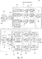
- Fig. 12 shows a schematic block diagram of a multi-stage correlator 122 of a data receiver 110, according to an embodiment.
- the multi-stage correlator 122 comprises three correlation stages, in detail, a first correlation stage 124 (cf. Fig. 10 ), a second correlation level 128 (cf. Fig. 11 ) and a third correlation stage 129.
- the first correlation stage 124 can take over a preamble correlation
- the second (128) and the third (129) correlation stage can take over a sequence correlation (127).
- the input signal 121 of the multistage correlator 122 may comprise P subband signals.
- the P subband signals can be obtained, for example, by the filter bank (e.g. matched filter) 132.
- the P subband signals present at the input of the multistage correlator 122 are indeed based on the broadband signal 120 (see FIG Fig. 6 ), but it is irrelevant how the broadband band signal 120, which is applied to the antenna of the data receiver 110 (for example "in the air"), is broken down into the P subband signals. This can be done, for example, with the in Fig. 12 filter bank 132 shown, but just as with P narrow band receiver or a broadband receiver and another type of decomposition.
- the multi-stage correlator 122 can have a first intermediate memory (e.g. ring buffer) 170 which can be designed to temporarily store the P subband signals (e.g. provided by the filter bank 132).
- a first intermediate memory e.g. ring buffer 170 which can be designed to temporarily store the P subband signals (e.g. provided by the filter bank 132).
- the first correlation stage 124 can be designed to convert the P subband signals into which the broadband signal 120 is divided, in each case with the K preamble sections in the To correlate preamble section correlation 150 in order to obtain K section correlation results 152 (for example section correlation amplitudes) for the respective subband signal. Furthermore, the first correlation stage 124 can be designed to normalize the K section correlation results 152 as a function of a determined power p [n] (eg calculated over several subbands). For example, the first correlation stage 124 can be designed to normalize the section correlation results 152 by forming absolute squares, dividing by the determined power p [n] and calculating the roots of the quotients.
- the first correlation stage 124 can have K queue buffers (for example ring buffers) 153, which can be designed to temporarily store the respective section correlation results 152, wherein the plurality of queue buffers 153 can have different storage lengths, the storage lengths of the K queue buffers 153 differing from the respective Preamble sections of the preambles of the partial data packets 142 may be dependent. Furthermore, the first correlation stage 124 can be designed to combine (e.g. add) the K section correlation results 152 temporarily stored in the K queue buffers 153 in order to obtain a subset of correlation results 158 for each of the subband signals, and to obtain a first set of correlation results 156, having the subsets of correlation results 158 for the P subbands.
- the first correlation stage 124 can furthermore have a (eg two-dimensional) output queue buffer (eg ring buffer) 172 which can be designed to temporarily store the first set of correlation results 156 of the first correlation stage 124.
- the second correlation stage 128 can have a group correlation 165, which can be designed to select groups of correlation results based on a group correlation pattern from the first set of correlation results 156 'of the first correlation stage 124 temporarily stored in the output queue buffer (eg ring buffer) 172 combine (e.g. add) in groups to obtain a second set of correlation results 166.
- the second correlation stage 128 may have a (e.g., two-dimensional) output queue buffer (e.g., ring buffer) 174, which may be designed to temporarily store the second set of correlation results 166 of the second correlation stage 128.
- the third correlation stage 129 can have a group sequence correlation 180, which can be designed to identify from the data in the output queue buffer (eg Ring buffer) 174 cached second set of correlation results 166 'of the second correlation stage 128 to select groups of correlation results based on a group sequence correlation pattern and to combine (eg add) in groups in order to obtain a third set of correlation results 182.
- the third correlation stage 129 can have a (eg, two-dimensional) output queue buffer (eg, ring buffer) 176, which can be designed to temporarily store the third set of correlation results 182 of the third correlation stage 129.
- the third correlation stage 129 can be designed to provide the correlation results in a form suitable for a subsequent packet detection 134.
- the third correlation stage can be designed to detect N S sequences of partial data packets.
- the group sequence correlation 180, the output queue buffer memory 176 and the packet detection N s -fach can be implemented.
- Ring buffers for storing intermediate results are arranged between the individual processing blocks.
- the depth of this ring buffer is given by the processing length of the subsequent processing block.
- the preamble can be divided into K sections of length L K , each of which is standardized individually and then added.
- the sections can be selected to be overlapping or non-overlapping.
- a value in the range 1 ... L K can be selected for the shift D K between the individual sections.
- D K L K
- non-overlapping sections are obtained.
- Fig. 13 shows a schematic view of an exemplary division of a preamble 190, according to an embodiment.
- the preamble 190 comprises 12 preamble symbols 144, the preamble 190 according to a first example being divided into three non-overlapping sections 192 of four preamble symbols 144 each, and the preamble 190 according to a second example being divided into five overlapping sections 192 of four preamble symbols 144 each will.
- the subdivision into sections 192 and their separate normalization can considerably improve the immunity to impulse-like interference.
- the division allows a reduction in the number C P of the channels to be processed in parallel (for example by reducing the overlap of the subband signals, ie by reducing the oversampling M F in the frequency direction).
- the result of the preamble correlation 124 is normalized, real-valued correlation amplitudes that result from the addition of the corresponding values of the individual sections.
- the results of the individual sections can be shifted over time by selecting the depths of the ring buffers following the normalization. Since the correlation takes place exclusively in the time direction, the number C P of the channels remains unchanged.
- the normalized correlation amplitudes of the M G preambles of the partial data packets 142 of a group can be added in the group correlation 128. This can be done by means of the temporal structure of a group described by T G and the frequency structure of a group described by S G. Since the correlation here also takes place in the frequency direction, the number of channels is reduced from C P to C G.
- the normalized correlation amplitudes of the N G groups of a sequence can be added in the group sequence correlation. This can be done by means of the temporal structure described by T PG, i and the frequency structure of the respective group sequence described by Sp Gi. Since there is also a correlation in the frequency direction here, the number of channels is reduced from C G to Cs.
- M F is the oversampling factor in the frequency direction.
- the factor M F can be adapted to the length L K of the sections of the preamble correlation.
- a conventional implementation can be used M. F. ⁇ 2 ⁇ L. K are valid. A method for reducing the factor M F to lower values is described below.
- B. G B. G
- standard ⁇ ⁇ f T B. G
- B G can use the bandwidth of the group and B.
- C. S. C. P. - M. F. ⁇ M. ⁇ ⁇ B. G , standard + B. PG , standard
- Table 1 contains the parameter values for two examples. With regard to the structure of a data packet, the only difference between the two examples is the carrier spacing ⁇ f T. In both examples, the relative bandwidth of a group was chosen in such a way that the number of channels is significantly reduced by the group correlation. This is particularly important in example 2.
- parameter Formula symbol example 1 Example 2 Band width B.
- Fig. 14 shows a schematic block diagram of a section of the in Fig. 12 first correlation stage 124 shown as well as the provision of the subband signals upstream of the first correlation stage 124, which takes place here by way of example with a filter bank (eg matched filter bank) 132 and the buffer (eg ring buffer) 170, according to an embodiment.
- Fig. 14 shows the signals and the circular buffer 170 of the preamble section correlation 150.
- the circular buffer 170 may be of size C P ⁇ (M T * L K ).
- Fig. 15 shows a schematic view of the preamble section correlation, carried out by the first correlation stage, of the subband signals temporarily stored in the ring buffer, including the combination of the section correlation results, according to an exemplary embodiment.
- M T successive columns of the ring buffer can be combined into one column with M T ⁇ Cp elements.
- the ring buffer 170 then has the size (M T * C P ) * L K.
- the correlation can now take place in parallel via M T * Cp channels and for each channel M T Deliver output values.
- M T sampled values of the subband signals which can correspond, for example, to M T output vectors of a matched filter bank, can be combined to form a column in the ring buffer.
- the values of the ring buffer can be stored in the memory column by column, ie starting with the values in the first column and ending with the values in the last column.
- the variants C P ⁇ (M T * L K ) and (M T * C P ) ⁇ L K are equivalent in the memory.
- the power calculation 151 shown follows the same sequence, but instead of the multiplication with the reference symbols, the square of the values of the values is calculated.
- Fig. 16 shows a schematic block diagram of a section of the in Fig. 12 first correlation stage 124 shown, according to an embodiment.
- the first correlation stage 124 can be designed to carry out a normalization 155 of the section correlation results 152 in order to obtain normalized section correlation results 152 '.
- the first correlation stage 124 can be designed to temporarily store the normalized section correlation results 152 'in the queue buffers 153 and to combine 154 (eg add) the normalized section correlation results 152' buffered in the queue buffers 153.
- Fig. 16 shows the normalization 155 and the subsequent addition of the results of the sections.
- ring buffers 153 can be used as delay elements in order to delay the results in accordance with the time structure of the sections.
- Fig. 17 shows a schematic block diagram of the second correlation stage 128 of the multi-stage correlator 122 of the data receiver, according to an embodiment.
- the second correlation stage 128 can be designed to carry out a group correlation 165 of the first set of correlation results 156 ′ buffered in the output queue buffer (eg ring buffer) 172 of the first correlation stage 124 in order to obtain a second set of correlation results 166.
- Fig. 17 shows the signals and the ring buffer of the group correlation.
- Fig. 18 shows a schematic view of a two-dimensional memory structure of the output queue buffer (e.g. ring buffer) 172 of the first correlation stage 124 and the group correlation 165 carried out by the second correlation stage 128, in the case of which from the first set of correlation results that is stored in the output queue buffer (e.g. ring buffer) 172 of the first correlation stage 124 is cached, groups of correlation results 160 are selected based on a group correlation pattern and combined 164 in groups.
- the output queue buffer e.g. ring buffer
- Fig. 18 shows the sequence of the group correlation 165.
- the M G sub-columns to be added, each with C G values move horizontally and cyclically through the ring buffer.
- the number of channels in the group correlation is reduced from Cp to C G. This reduction is greater, the greater the normalized bandwidth B G, norm of the group.
- Fig. 19 shows a schematic block diagram of a section of the in Fig. 12 third correlation stage 129 shown, according to an embodiment.
- the third correlation stage 129 can be designed to carry out a group sequence correlation 180 of the second set of correlation results 166 ′ buffered in the output queue buffer (eg ring buffer) 174 of the second correlation stage 128 in order to obtain a third set of correlation results 182.
- the third correlation stage 129 can be designed to detect Ns sequences of partial data packets 142.
- the group sequence correlation can be implemented 180 N s times.
- Fig. 19 shows the signals and the ring buffer of the group sequence correlation.
- the N S output signals c S, 1 [n], ... c S, Ns [n] form the output signals of the packet correlator.
- a plurality of groups can alternatively also be used.
- the one in the lower part of Fig. 12 The part shown with the group correlation 165 and the subsequent group sequence correlations 180 is present several times in this case.
- the error in the preamble correlation acts as a limiting factor here.
- matched filtering which can take place, for example, with a matched filter bank
- Fig. 20 shows how this situation can be used to reduce the number of channels, ie the number of subband signals, which can be done, for example, by reducing the number of channels of a matched filter bank 132.
- the subband signals are provided by a matched filter bank, since this is the preferred embodiment in practice. In principle, however, the provision can take place with any method that can provide a set of subband signals that are equivalent for further processing. In other words: the type of provision of the subband signals is not relevant for the processing.
- Fig. 20 Shows in detail Fig. 20 a schematic view of a reduction in the number of channels of a matched filter bank 132 from an f / 8 matched filter bank 132_1 to an f / 4 matched filter bank 132_2.
- every second filter of the f / 8 matched filter bank can be omitted and the outputs of the resulting f / 4 matched filter bank can be shifted by ⁇ f sym / 16 with two mixers each, so that a frequency grid as in an f / 8 matched filter bank.
- the computational effort in the matched filter bank 132 can be reduced by approximately half.
- the mixers after the f / 4 matched filter bank 132_2 can be saved by using two different preambles rotated with the corresponding mixing frequencies or their sections as reference symbols in the correlation. This is in Fig. 21 shown for a single channel. Although this procedure is not equivalent with regard to the complex-valued result of the correlation, only the square of the amount of the result is required in further processing, so that the deviation has no effect.
- the rotation of the reference symbols takes place once during the initialization of the components.
- Fig. 23 shows a schematic block diagram of the first correlation stage 124, according to a further embodiment.
- the first correlation stage 124 is designed to shift a subband signal provided by the f / 4 matched filter bank by ⁇ f sym / 16 using two mixers, and to carry out a preamble section correlation 150 for each of the ⁇ f sym / 16 shifted versions of the subband signal to obtain preamble section results and to perform normalization 155 of the preamble section results to obtain normalized preamble section results and to temporarily store the normalized preamble section results in the queue buffers 153 and to combine the cached normalized preamble section results 154 to calculate for the by ⁇ f sym / 16 shifted versions of each subband signal to obtain a correlation intermediate result, and to perform a maximum formation 157 of the correlation intermediate results in order to obtain a correlation result for each subband signal.
- the data transmitter sends its packet at any time.
- the recipient has no or only imprecise knowledge of the transmission time at which the transmission begins. This point in time must be determined in the receiver by means of a detection.
- the preamble is typically divided into several subsections.
- Embodiments of the present invention take a different approach, in which the correlation is subdivided into several partial correlations and then the partial results are added can be summarized in an overall result.
- a prerequisite for this methodology can, for example, be that the sequence is the same in all subsections. If this is the case, the correlation can be divided into a preamble correlation, an (optional) group correlation and a group sequence correlation, as described in section 2.
- This methodology reduces the required computing power of the detector enormously. This means that either cheaper hardware can be used or the number of jump patterns supported can be increased.
- the correlator not only consists of a single-stage correlator, there are at least two correlators, the second correlator operating on the basis of the results of the first correlator.
- the results in the stages can be stored temporarily (e.g. in a database or a ring buffer).
- a correlation can first be carried out using the preamble sequence sections. These results can then be combined in a second correlator to form a group result. On the basis of the group correlation, the group sequence correlation can then be carried out, which provides the overall result for the detection.
- the results can now be loaded from the memories of the various preamble correlations according to the jump pattern and be combined. Further processing is carried out in the same way as the procedure described above.
- the first correlation stage has at least two parallel correlators.
- the results from the multiple correlates of the first stage can be loaded and combined according to the jump pattern.
- Fig. 13 the example of a preamble with 12 symbols shows how the performance of the correlation against frequency offsets can be increased by dividing the preamble into sections that are individually correlated and then added incoherently.
- the threshold value can be chosen after the correlation based on the background noise. Due to the length of the correlation, additional noise averaging is carried out, which limits the number of false detections with a suitable threshold value. All correlation values above the threshold value represent the beginning of a transmitted data packet with a very high probability. The higher the receiving power of the transmitted data packet at the data receiver, the higher the correlation value and thus the probability that a data packet was transmitted.
- the amounts of the individual partial data packets can be weighted according to the estimated disruption. This means that disturbed partial data packets have less of an impact than partial data packets without a disturbance.
- a non-linear function is necessary for normalization. This can, for example, as described above, represent the weighting of the amounts according to the estimated disturbance.
- the subpackets can be normalized to the estimated disturbance. This normalization can take place either before the correlation or also after the correlation.
- a more specific example of this normalization is the normalization of the correlation results to the received signal power. For this purpose, the squares of the amounts are formed for all symbols in the preamble and then the sum is calculated.
- the correlation result is also normalized to the received signal power. As the symbols received during the disturbance in general however deviate from the expected preamble sequence, the correlation result is significantly lower than in the case of an undisturbed signal.
- the normalization thus ensures that the correlation result is well below one and thus the probability of a false detection decreases.
- the correlation result can also be divided directly by the square root of the determined signal power.
- the normalization can also take place before the correlation.
- the signal power is calculated in the same way as above and then the root is taken. This result is applied to each input symbol using division.
- the correlation result can be normalized to the received signal power of the preamble. This can be done in several ways.
- data symbols occur before and / or after the received preamble, these data symbols can also (partially) be included in the calculation of the power.
- the number of symbols which are used to determine the power is thus greater than the number of preamble symbols for the correlation.
- the received signal power can be determined using at least one data symbol.
- either the same number of symbols can be used as for the correlation or neighboring symbols can be included again.
- the partial areas of the correlation can be normalized separately. Either a separate determination of the performance or a joint performance determination can be made for each sub-area.
- the normalization can be carried out separately for each channel. If it can be assumed that disturbances always occupy at least two of the channels, the performance can also be determined jointly for at least two channels.
- the normalization in a multichannel receiver, can be carried out in parallel on all channels, with the power determination also being able to take place across several channels.
- results from different points in time can be added, depending on the temporal position of the sequence.
- a solution to avoid this problem is to create a buffer structure for the partial correlation results.
- n-ring buffers can be used for the n-partial correlations.
- the time dependency between the partial correlations can be established through the length of each ring buffer. That is, the length of the buffer determines the duration of the delay.
- the oldest entries of all ring buffers can be added up before they are discarded in the next step.
- a buffer structure can be used at the output of the partial correlations.
- the time delay (see Fig. 16 ) realized.
- the frequency offset (random and / or systematic offset) between the data transmitter and data receiver can be a multiple of the symbol rate, it is necessary to use a multi-channel correlator.
- a filter bank can be used in advance, which generates the symbols for each channel.
- the filter bank of the multichannel correlator can have a different frequency oversampling than the following correlator.
- the symbols of the filter bank can be multiplied by a complex exponential oscillation (corresponds to a digital frequency shift), the choice of exponential oscillation being dependent on the frequency offset.
- the reference sequence can also be multiplied with the exponential oscillation.
- a separate reference sequence can be used for each frequency line to be generated from the data of the filter bank, the adapted reference frequency being generated from the original reference sequence by means of multiplication with the corresponding exponential oscillation.
- Another possibility for reducing the channels results from the finding that the high frequency resolution of the preamble correlation is not required for the subsequent group and group sequence correlation.
- the number of channels after the first correlation stage can be reduced, which entails less computational effort and smaller memories.
- a maximum formation can be carried out over adjacent channels.
- the smaller value (s) are discarded for further processing.
- Fig. 24 shows a schematic block diagram of a radio transmission system with a data transmitter 100 and a data receiver 110, according to an embodiment of the present invention.
- the data receiver 110 can be configured to receive a signal 120 from a data transmitter 100, the signal 120 having at least two pilot sequences 144_1, 142_2 (and 144_3) that are distributed in time and optionally in frequency according to a (transmitter-side) pilot pattern at least one second pilot sequence 144_2 (and 144_3) of the at least two pilot sequences 144_1, 142_2 (and 144_3) has a time-variable frequency shift ⁇ f (frequency drift) compared to a first pilot sequence 144_1 of the at least two pilot sequences 144_1, 142_2 (and 144_3).
- ⁇ f frequency drift
- the data receiver may have a detector 130 (e.g. packet detector) with a correlator 122 which is configured to detect the at least two pilot sequences 144_1, 142_2 (and 144_3) (e.g. in the received signal 121) based on a correlation pattern, wherein the correlation pattern is adapted in frequency to the time-varying frequency shift in order to reduce (for example to compensate) an influence of the time-varying frequency shift ⁇ f.
- a detector 130 e.g. packet detector
- a correlator 122 which is configured to detect the at least two pilot sequences 144_1, 142_2 (and 144_3) (e.g. in the received signal 121) based on a correlation pattern, wherein the correlation pattern is adapted in frequency to the time-varying frequency shift in order to reduce (for example to compensate) an influence of the time-varying frequency shift ⁇ f.
- the signal 120 has, for example, two or three pilot sequences 144_1, 144_2 (and 144_3).
- the signal 120 can have up to n pilot sequences 144_1 to 144_n, where n is a natural number greater than or equal to two, n 2.
- the signal 120 can have a data packet 141, wherein the data packet 141 can have the at least two pilot sequences 144_1 and 144_2.
- the pilot pattern can indicate a time interval between the at least two pilot sequences 144_1 and 144_2.
- the signal 120 can have at least two partial data packets 142_1, 142_2 (and 142_3) (see section 1), the at least two partial data packets 142_1, 142_2 (and 142_3) each having a pilot sequence 144_1, 142_2 (and 144_3) , and wherein the at least two partial data packets 142_1, 142_2 (and 142_3) are distributed in time and optionally in frequency in accordance with a hop pattern 140.
- the pilot pattern can indicate a distribution of the at least two pilot sequences 142_1, 142_2 (and 142_3) in terms of time and optionally in terms of frequency.
- the pilot pattern can be the same as the jump pattern 140.
- the pilot pattern can be derived from the jump pattern 140, for example if the jump pattern 140 defines absolute times of the partial data packets 142_1, 142_2 (and 142_3) instead of relative times or the pilot sequences 142_1, 142_2 (and 142_3) are located at other positions within the Partial data packets 142_1, 142_2 (and 142_3) are located as those defined by the jump pattern 140.
- the correlation pattern used by the correlator 122 can be the same as a (transmitter-side) pilot pattern.
- the correlation pattern used by the correlator 122 can be derived from the (transmitter-side) pilot pattern, e.g. if the correlation pattern already takes into account transmission properties of the communication channel used (with the exception of the time-variable frequency shift ⁇ f).
- an expected distribution of the at least two pilot sequences 144_1, 144_2 (and 144_3) indicated by the correlation pattern does not match the actual distribution of the at least two pilot sequences 144_1, 144_2 (and 144_3) of the received signal.
- the data receiver 110 (e.g., the detector 130 of the data receiver 110 or the correlator 122 itself) can therefore be configured to adjust the correlation pattern in frequency to reduce (e.g., compensate) for an influence of the frequency shift ⁇ f.
- the data receiver 110 can be configured to estimate the time-variable frequency shift of the at least one second pilot sequence 144_2 compared to the first pilot sequence 144_1 and to adapt the correlation pattern in frequency based on the estimated time-variable frequency shift, e.g. to adjust the correlation pattern in frequency by to shift the estimated temporally variable frequency shift or to apply the estimated temporal changes to the correlation pattern.
- the data receiver 110 can adjust the correlation pattern in the frequency by +100 Hz / s (for example, apply a time-variable frequency shift of +100 Hz / s) to an influence to reduce or compensate for the time-variable frequency shift. Accordingly, the data receiver 110 can adjust the correlation pattern in the frequency by -300 Hz / s with an estimated time-variable frequency shift of, for example, -300 Hz / s (for example, apply a time-variable frequency shift of -300 Hz / s) in order to avoid an influence of the to reduce or compensate for temporally variable frequency shifts.
- the data receiver 110 (for example the detector 130 of the data receiver 110 or the correlator 122 itself) can also be configured in exemplary embodiments to detect the at least two pilot sequences 144_1, 144_2 (and 144_3) based on a correlation pattern selected from a set of correlation patterns, wherein the correlation patterns of the set of correlation patterns reduce or compensate for different influences of time-varying frequency shifts.
- the data receiver 110 (or the correlator 122) can be configured to estimate the time-variable frequency shift of the at least one second pilot sequence 144_2 compared to the first pilot sequence 144_1, and to select a correlation pattern from the set of correlation patterns as a function of the estimated frequency shift in order to obtain the selected correlation pattern.
- a suitable correlation pattern can also be selected from the set of correlation patterns in order to reduce the influence of the time-variable frequency shift.
- the correlation pattern of the set of correlation patterns can be derived from the same pilot pattern, which describes the distribution of the at least two pilot sequences 144_1 and 144_2 in the data packet 141, and applied with different, time-variable frequency shifts, so that a respective correlation pattern has an influence on a respective one Time-varying frequency shift reduced or compensated.
- the correlation pattern of the set of correlation patterns can also be derived from the same jump pattern that describes the distribution in time and optionally in the frequency of the at least two partial data packets and can be subjected to different, time-variable frequency shifts, so that a respective correlation pattern an influence of a respective time-varying frequency shift is reduced or compensated.
- a first correlation pattern of the set of correlation patterns can have a time-varying frequency shift of, for example, +100 Hz / s applied to it, in order to reduce or compensate for an influence of a time-varying frequency shift of, for example, +100 Hz / s.
- a second correlation pattern of the set of correlation patterns can have a time-varying frequency shift of, for example +200 Hz / s must be applied in order to reduce or compensate for the influence of a time-variable frequency shift of, for example, +200 Hz / s.
- the time-variable frequency shift e.g. in the case of a movable data transmitter 100 and / or data receiver 110, can be caused by a relative change in movement between the data transmitter 100 and the data receiver 110.
- the time-variable frequency shift can also result, additionally or alternatively, from a time-variable mismatch between the oscillators of the data transmitter and the data receiver.
- one of the data transmitter 100 and the data receiver 110 can be a satellite or a relay, while the other of the data transmitter 100 and the data receiver 110 can be a stationary station.
- the data transmitter 100 can have a transmission device (or transmission module, or transmitter) 102 which is designed to transmit the signal 120.
- the transmission device 102 can be connected to an antenna 104 of the data transmitter 100.
- the data transmitter 100 can have a receiving device (or receiving module, or receiver) 106 which is designed to receive a signal.
- the receiving device 106 can be connected to the antenna 104 or a further (separate) antenna of the data transmitter 100.
- the data transmitter 100 can also have a combined transceiver.
- the data receiver 110 can have a receiving device (or receiving module, or receiver) 116, which is designed to receive the signal 120 in order to provide a received signal 121.
- the receiving device 116 can be connected to an antenna 114 of the data receiver 110.
- the data receiver 110 can have a transmission device (or transmission module, or transmitter) 112 which is designed to transmit a signal.
- the transmitting device 112 can be connected to the antenna 114 or a further (separate) antenna of the data receiver 110.
- the data receiver 110 can also have a combined transceiver.
- Fig. 25 shows a schematic block diagram of a correlator 122, according to an embodiment of the present invention.
- the correlator 122 can have at least two correlation units 118_1 and 118_2 operating in parallel, wherein a first correlation unit 122_1 of the at least two correlation units 118_1 and 118_2 operating in parallel can be configured in order, based on the correlation pattern, to perform correlations of the at least two pilot sequences 144_1, 144_2 ( and 144_3) with corresponding reference sequences in order to obtain a set of correlation results 119_1 of the first correlation unit 118_1, wherein a second correlation unit 118_2 of the at least two correlation units 118_1 and 118_2 operating in parallel can be configured to perform correlations of the at least two pilot sequences 144_1 To carry out 144_2 (and 144_3) with corresponding reference sequences in order to obtain a set of correlation results 119_2 of the second correlation unit 118_2.
- the at least two correlation units 118_1 and 118_2 operating in parallel can be configured to use correlation patterns that are differently adapted in terms of frequency in order to reduce or compensate for influences of different time-varying frequency shifts during detection.
- the data receiver 110 can be configured to differently adapt the correlation pattern used in the at least two correlation units 118_1 and 118_2 operating in parallel in terms of frequency in order to reduce or compensate for influences of different frequency shifts.
- Fig. 26 shows a schematic block diagram of a correlator 122, according to a further exemplary embodiment of the present invention.
- the multi-level correlator 122 can have a first correlation level 124 and at least one second correlation level 128 (and 129) following the first correlation level 124, which works based on correlation results 125 of the first correlation level 124, wherein at least one correlation pattern that in at least a correlation stage from which at least one second correlation stage 128 (and 129) is used, in which the frequency is adapted in order to reduce or compensate for the influence of the frequency shift which is variable over time.
- the multistage correlator 122 can have a first correlation stage 124 and a second correlation stage 128 that operates based on correlation results 125 of the first correlation stage 124, a correlation pattern that is used in the second correlation stage 128 being adapted in frequency to to reduce or compensate for the influence of the time-variable frequency shift.
- the multi-level correlator 122 can have a first correlation level 124, a second correlation level 128, which operates based on correlation results 125 of the first correlation level 124, and a third correlation level 129, which operates based on correlation results 126 of the second correlation level 128, with a correlation pattern , which is used in the second correlation stage 128 and / or a correlation pattern which is used in the third correlation stage 129 is adapted in frequency in order to reduce or compensate for the influence of the time-variable frequency shift.
- the first correlation stage 124 can be configured to perform a preamble correlation, as described in detail in Sections 2 and 3.
- the first correlation stage 124 can be configured, for example in relation to FIG Fig. 10 has been explained in order to correlate the received signal 121 or a version derived therefrom with a plurality of pilot sequence sections 150 which correspond to different sections of the pilot sequences of the at least two partial data packets 142_1, 142_2 (and 142_3) correspond to obtain a plurality of section correlation results 152, wherein the first correlation stage 124 can be configured to combine 154 the plurality of section correlation results 152 to produce a set of correlation results 156 or a subset of correlation results 158 as correlation results 125 of the first correlation stage 124 to get.
- the first correlation stage 124 can of course also be configured to detect at least two pilot sequences that are not contained in at least two partial data packets 142_1, 142_2 (and 142_3) but in a single data packet 141 (cf. Fig. 24 ).
- the first correlation stage 124 can be configured to correlate the received signal 121 or a version derived therefrom with a plurality of pilot sequence sections, which correspond to different sections of the at least two pilot sequences 144_1 and 144_2, in order to assign a plurality of section correlation results 152
- the first correlation stage 124 may be configured to combine 154 the plurality of section correlation results 152 in order to obtain a set of correlation results 156 or a subset of correlation results 158 as correlation results 125 of the first correlation stage 124.
- the second correlation stage 128 can be configured to carry out a group correlation, provided that the signal 120 has a plurality of partial data packets 142_1 to 142_n, which in groups have the same relative group jump pattern 140_1 and 140_2, as in sections 2 and 3 has been described in detail.
- the second correlation stage 128 can be configured, for example in relation to FIG Fig. 11 was explained to select from the set of correlation results 156 of the first correlation level 124 groups of correlation results 160 based on a group correlation pattern 162, which is derived from a group jump pattern, and to combine 164 in groups to obtain a set of correlation results 166 of the second correlation level 128 .
- the second correlation stage 128 can of course also be configured to detect a multiplicity of pilot sequences that are not contained in a multiplicity of partial data packets 142_1 to 142_n, but rather in a single data packet 141 and within the data packet 141 the same relative in groups Have group pilot patterns.
- the second correlation stage 128 can be configured to determine from the Set of correlation results 156 of the first correlation level 124 to select and combine 164 groups of correlation results 160 based on a group correlation pattern 162 derived from the group pilot pattern in order to obtain a set of correlation results 166 of the second correlation level 128.
- the third correlation stage 129 can be configured to carry out a group sequence correlation, provided that the at least two groups of partial data packets form a sequence and have a group sequence jump pattern relative to one another, as was described in detail in Sections 2 and 3.
- the third correlation stage 129 can be configured, for example with reference to FIG Fig. 12 in order to select from the set of correlation results 166 of the second correlation level 128 groups of correlation results based on a group sequence correlation pattern which is derived from the group sequence jump pattern and to combine them in groups to obtain a set of correlation results 182 of the third correlation level 129.
- the third correlation stage 129 can of course also be configured to detect a plurality of pilot sequences that are not contained in a plurality of partial data packets 142_1 to 142_n, but rather have a relative group sequence pilot pattern in a single data packet 141 and within the data packet 141 .
- the third correlation stage 129 can be configured to select from the set of correlation results 166 of the second correlation stage 128 groups of correlation results based on a group sequence correlation pattern which is derived from the group sequence pilot pattern and to combine them in groups to form a set of correlation results 182 of FIG third correlation stage 129 to be obtained.
- a correlation pattern that is used in the second correlation stage 128 and / or in the third correlation stage 129 can be adjusted in terms of frequency in order to reduce or compensate for the influence of the frequency shift.
- the data receiver 110 (e.g. or the detector 130 of the data receiver 110 or the multi-stage correlator 122 itself) can be configured to adjust the frequency of a correlation pattern that is used in the second correlation stage 128 and / or in the third correlation stage 129, to reduce or compensate for the influence of the frequency shift.
- the data receiver 110 can be configured to adjust the frequency of the group correlation pattern used in the second correlation stage 128 in order to reduce or compensate for the influence of the time-varying frequency shift. Furthermore or alternatively, the data receiver 110 can be configured to adjust the frequency of the group sequence correlation pattern used in the third correlation stage 129 in order to reduce or compensate for the influence of the frequency shift which is variable over time.
- pilot sequences e.g. of a data packet with several pilot sequences or of several data packets each with at least one pilot sequence
- receiver of a radio transmission system.
- preamble is used to designate the pilot sequence, i.e. for the symbols to be used for correlation, regardless of the arrangement of the preamble within the data packets.
- preamble used below therefore includes the cases referred to in the English-language literature as preamble, midamble and postamble. In the following, the method is explained using the example of a preamble arranged exactly in the middle, but it applies in the same way to other arrangements.
- detector 130 e.g. packet detector
- filter bank e.g. a matched filter bank
- the further correlation stages 127 either consist of a second correlation stage 128 (cf. Figure 5a ) or from a second 128 and a third 129 correlation level (cf. Figure 5b ) together.
- exemplary embodiments of the data receiver 110 can be applied to all four in Fig. 7 The cases shown are used, for example when the data receiver 110 is to receive a large number of data packets which are transmitted asynchronously by different data transmitters 100 and on different frequencies within an assigned frequency band. As a result, the broadband signal 120 at the input has a significantly higher bandwidth than the partial data packets 142_1-142_n.
- Embodiments of the data receiver 110 are particularly relevant in case 4, which enables a particularly high degree of parallel asynchronous packet transmissions.
- each partial data packet 142_1-142_n contains its own preamble 144_1-144_n (cf. Fig. 24 ).
- the time and frequency sequence of the partial data packets 142_1-142_n is referred to below as the (partial data packet) sequence.
- the throughput of the transmission system can be further increased in that different data transmitters 100 use different sequences; as a result, the probability of collisions of the partial data packets 142_1-142_n from different data transmitters 100 decreases.
- Embodiments of the present invention are used, for example, in satellite communication systems, but generally whenever frequency drifts are to be expected.
- a high Doppler frequency is a problem for the coherent detection of telegrams if the transmission time (e.g. as in [4]) is long.
- Figure 28a Shows in detail Figure 28a a Doppler shift in kHz plotted against an elevation angle of the LEO satellite while Figure 29b shows a delta-Doppler shift in Hz / s plotted over an elevation angle of the LEO satellite, in each case for a carrier frequency f c of 1 GHz and an earth orbit at an altitude of 700 km.
- the starting point of the exemplary embodiments described below is the multistage correlator 122 described in Sections 2 and 3, which carries out the packet detection with the aid of a multistage correlation. According to the exemplary embodiments described below, this is modified to the effect that the reception of packets (e.g. Data packets 141 or partial data packets 142_1-142_n, cf. Fig. 24 ) is possible with the frequency drifts mentioned above.
- packets e.g. Data packets 141 or partial data packets 142_1-142_n, cf. Fig. 24
- the time-variant Doppler shift described above results in frequency shifts of up to 200 Hz / s.
- the pilot sequences are introduced in each of the 24 radio bursts (partial data packets 142_1-142_24). The interval between the first and the last pilot sequence is thus also approx. 4 seconds.
- the data rate of the radio transmission system is around 2400 Sym / s.
- the frequency resolution of the multi-stage detector according to Sections 2 and 3 is typically 1/8 of the symbol rate in Hz. In other words, the frequency oversampling during the correlation is typically 8 times higher than the symbol rate in Hz.
- exemplary embodiments of the present invention are not limited to the so-called telegram splitting method [5]. Rather, exemplary embodiments of the present invention can generally be used for a detection of packet transmissions with divided or distributed pilot sequences. For example, there are systems with a preamble and a postamble. Then the duration between the preamble and postamble is used as a reference for the time-variant frequency drift.
- the correlator 122 can be modified. In detail, only part of the correlator can be modified when using the multistage correlator 122 (see section 4.3).
- Fig. 29 shows a diagram of a correlation pattern 200 as it is used in Sections 2 and 3 above.
- the abscissa describes the time, divided into time correlation steps which, according to Sections 2 and 3, can be, for example, half the symbol duration, while the ordinate describes the frequency, divided into frequency steps of the correlation, which, as mentioned above, e.g. 1/8 of the symbol rate can be.
- the result is an average interval of one second between the pilot sequences ( or partial data packets).
- the frequency difference between the first and last pilot sequences (or partial data packets) is 600 Hz.
- the frequency offset is greater than the step size from the third pilot sequence (or partial data packet). From the fifth pilot sequence (or partial data packet) there are already two step sizes.
- the correlation pattern (or correlation pattern) of the correlator 122 is modified so that, for example, the next higher frequency element is selected from the third pilot sequence (or partial data packet), the telegram can be detected again. From the fifth pilot sequence (or partial packet) onwards, the frequency element after the next can then be selected, as shown in FIG Fig. 30 is shown.
- FIG. 30 Shows in detail Fig. 30 in a diagram based on the in Fig. 29 correlation pattern 200 shown, a modified correlation pattern 202, according to an embodiment of the present invention.
- the respective frequency lines are modified in accordance with the frequency drift to be expected. If the frequency drift is greater, for example, the modified correlation pattern must be adapted accordingly.
- the correlation pattern (or correlation pattern) can be adapted accordingly so that values below the correlation pattern follow Fig. 30 must be chosen.
- the correlation pattern when transmitting telegrams or data packets with distributed / divided pilot sequences and / or telegram splitting, the correlation pattern (or correlation pattern) can be modified according to an expected frequency drift so that the telegram or data packet can be detected.
- the smaller change of 50 Hz / s results in a maximum change of 200 Hz over the four-second telegram duration (between the first and last pilot sequence (or partial data packet)). This means that the correlation does not have to be modified for successful detection, since the maximum difference is smaller than the step size of the correlation.
- the last pilot sequence (or partial data packet) has a frequency difference of approximately 200 Hz compared to the first pilot sequence (or partial data packet). This value is greater than half the step size of the correlator 122. Since the last pilot sequence (or partial data packet) does not lie exactly on a correlation line, the "energy" of the correlation is divided between the neighboring lines. This is the one after the in Fig. 29 shown index, as well as the next following index.
- the correlation pattern can be used when transmitting telegrams or data packets with distributed / divided pilot sequences and / or telegram splitting be modified according to an expected frequency drift so that detection of the telegram is improved.
- the starting point is again the system according to [5] with a symbol rate of approx. 2400 sym / s, 24 partial data packets 142_1-142_24 and a transmission time of approx. Four seconds.
- the mode of operation of the multi-stage correlator 122 is briefly explained below (cf. Sections 2 and 3.
- the multi-stage correlation takes place in several separate stages, each of which is based on the results of the previous stage.
- the first stage is the so-called preamble correlation 124, which is based on the output signal of the optional matched filter bank 132, which divides the input signal 120 of the receiver 110 into overlapping subband signals.
- the preamble correlation 124 correlates the symbols within a pilot sequence or a partial data packet in the necessary sub-bands.
- the preamble correlation therefore only works within a partial data packet, so the duration is limited to approx. 15 ms.
- the second stage is the so-called group correlation 128.
- the basic pattern comprises three partial data packets (or radio bursts) in [5]. According to [5], the duration of a basic pattern is approx. 316 ms.
- the third and last correlation stage includes what is known as the group sequence correlation 129, in which the results of the group correlation 128 are correlated over the entire core frame to form an overall result.
- the duration thus covers the entire four seconds, as mentioned at the beginning.
- the maximum frequency deviations in the preamble correlation 124 and the group correlation 128 are significantly smaller than the step size (or half the step size), it is not absolutely necessary to take into account the frequency drift in the first two correlation stages 124 and 128. In some exemplary embodiments, it is sufficient to modify the group sequence correlation 129. Of course, the group correlation 128 and the group sequence correlation 129 can also be modified in exemplary embodiments.
- the group sequence correlation can be modified as described in Chapter 4.1, whereby the intervals in time and frequency correspond to the intervals between the groups (of partial data packets that have the same group jump pattern in groups), whereby the duration of the group is also taken into account.
- Fig. 31 shows a schematic block diagram of a detector 130 with a multi-stage correlator 122, according to an embodiment of the present invention.
- Fig. 31 shows a sequence of the correlation in the detector 130 in the case of multi-stage correlation with modification for frequency drifts, with the in FIG Fig. 31 shown embodiment only the three-stage correlation is considered in more detail.
- Fig. 32 Shows in detail Fig. 32 a schematic block diagram of a detector 130 with a multi-level correlator 122, which has at least two third correlation levels (group sequence correlations) 129_1 and 129_2 that use correlation patterns that are differently adapted in frequency, according to an embodiment of the present invention.
- group sequence correlations group sequence correlations
- Fig. 32 it is assumed here by way of example that either no frequency drift or only a specific frequency drift can be present.
- a parallel correlation 129_1 and 129_2 and detection 134_1 and 124_2 can be carried out with different assumptions for the frequency drifts.
- Fig. 33 shows a schematic block diagram of a detector 130 with a multi-stage correlator 122, which has five third correlation stages (group sequence correlations) 129_1-129_5, which use correlation patterns that are differently adapted in terms of frequency in order to detect different time-varying frequency shifts (-200 Hz / s, -100 Hz / s, 0 Hz / s, 100 Hz / s, 200 Hz / s) according to an embodiment of the present invention.
- the detector 130 can furthermore have a selector 131 which is configured to select the correlation results of one of the five third correlation levels 129_1-129_5, based on which the detection is to take place, and to provide them to a packet detection 134.
- a five-fold parallel correlation shows 129_1-129_5 with five different assumptions, the frequency drifts in this case being from -200 Hz / s to + 200 Hz / s. Since in this case the detection would also have to run five times, the in Fig. 33
- a selector 131 is inserted after the group sequence correlation 129_1-129_5. It often happens that the actual frequency drift does not exactly match the assumptions. According to the description in Chapter 4.2 for the system from [5], up to 75 Hz / s can be tolerated without correction.
- the different assumptions are separated by 100 Hz / s. For example, if the frequency drift is 60 Hz / s, the telegram is correctly detected by both the 0 Hz / s and the +100 Hz / s correlation. The decoder would therefore have to process a packet twice.
- a selector 131 can only forward the highest value per time step and jump pattern (e.g. to a packet detection 134).
- Selector scenario 2 Controlled forwarding of (multiple) detections
- Fig. 34 shows a schematic block diagram of a data receiver 110 with a detector 130 with a multi-stage correlator 122, which has three third correlation stages (group sequence correlations) 129_1-129_3, the correlation results of which are used in three packet detections 134_1-134_3 for the detection of the pilot sequences, using of a selector, only the detection results of one of the packet detections 134_1-134_3 are provided for a decoder, according to an exemplary embodiment of the present invention.
- group sequence correlations group sequence correlations
- Fig. 34 shows multiple parallel group sequence correlations 129_1-129_3 and detections 134_1-134_3 for different frequency drifts with subsequent selector 131.
- a selector 131 is inserted after the detections 134_1-134_3.
- the task of the selector 131 is to recognize multiple detections and to forward a) none or b) only a limited number of multiple detections for the subsequent decoding 133.
- Case b) The detection of multiple detections as described in a) can be used to improve the decoder performance.
- the joint consideration of multiple detections can provide additional information that positively supports the decoding process.
- suitable multiple detections are selected and forwarded. Criteria for the selection of suitable multiple detection can be made both dynamically, e.g. by appropriate feedback 135 of the decoder 133, as well as permanently by preconfiguration.
- the selector 131 can clearly identify multiple detections by a feedback 135 of the decoder 133.
- the selector 131 forwards multiple detections in a controlled manner for the subsequent decoding.
- the frequency indices of the individual pilot sequences or the subpackets change due to the frequency drift.
- the indices are directly related to the jump patterns without frequency drift or can be derived from them.
- the jump patterns can thus also be adapted. This has the advantage that only the configuration parameters have to be adjusted, which is sometimes even possible dynamically.
- the hopping patterns can be adapted in accordance with the frequency drift (s) to be analyzed.
- the frequency drift can now also be included in the synchronization, but this increases the degrees of freedom and thus the complexity and computing power.
- the estimation of the frequency drift by the various assumptions in the detector can be used directly for the correction in or in front of the decoder.
- Fig. 35 shows a schematic block diagram of a data receiver 110 with a detector 130, a delta-Doppler compensator 137 and a decoder 133, according to an embodiment of the present invention.
- Fig. 35 shows an interplay of detection and decoding with compensation of the determined frequency drift.
- Fig. 36 shows a schematic block diagram of a data receiver 110 with a detector 130, a Doppler compensator 137 and a decoder 133, according to an embodiment of the present invention.
- Fig. 36 shows an interplay of detection and decoding with compensation of the determined frequency drift.
- Figures 35 and 36 show possibilities of how the determined frequency drift can be compensated or corrected before decoding 133.
- the frequency drift can be corrected directly in the decoder 133.
- the detector 130 generally notifies the decoder 133 of the number of the detected jump pattern, since this means that the symbols are extracted from the input signal.
- By modifying and, if necessary, expanding the jump pattern it is also known which frequency drift was successful in detection 130. From this, the frequency drift can be calculated and corrected again.
- the detected jump pattern number can be used to calculate back to the frequency drift and correct it.
- FIG. 3 shows a flow diagram of a method 300 for receiving a signal, according to an exemplary embodiment of the present invention.
- the method 300 comprises a step of receiving a signal from a data transmitter, the signal having at least two pilot sequences that are distributed in time according to a pilot pattern, at least one second pilot sequence of the at least two pilot sequences having a time-variable frequency shift compared to a first pilot sequence has at least two pilot sequences.
- the method further comprises a step of detecting the at least two pilot sequences based on a correlation pattern, the correlation pattern being adapted in frequency to the frequency shift which is variable over time is adapted to reduce an influence of the time-varying frequency shift.
- FIG. 3 shows a flow diagram of a method 310 for receiving a signal, according to a further exemplary embodiment of the present invention.
- the method 310 comprises a step 312 of receiving a signal from a data transmitter, the signal having at least two pilot sequences that are distributed in time according to a pilot pattern, with at least one second pilot sequence of the at least two pilot sequences having a time-variable frequency shift compared to one first pilot sequence which has at least two pilot sequences.
- the method further comprises a step 314 of detecting the at least two pilot sequences based on a correlation pattern selected from a set of correlation patterns, the correlation patterns of the set of correlation patterns reducing different influences of temporally variable frequency shifts.
- Embodiments provide a data receiver, the data receiver being adapted to receive a signal comprising a plurality of partial data packets [e.g. which are distributed according to a hopping pattern in the time and frequency], the plurality of partial data packets each having a part of a data packet, the data receiver having a multi-level correlator which is designed to carry out a multi-level correlation [e.g. of the received signal (e.g. in a first correlation stage) and a processed (e.g. by the first correlation stage) version of the received signal (e.g. in a second correlation stage)] in order to carry out the partial data packets [e.g.
- a second correlation stage of the multi-stage correlator is based on correlation results [e.g. based on the processed version of the received signal] of a first correlation stage of the multi-stage correlator operates.
- the multi-stage correlator can be designed to detect the plurality of partial data packets based on preambles of the same in the received signal.
- the plurality of partial data packets can be distributed in time and frequency in accordance with a hopping pattern, the multi-stage correlator being designed to convert the plurality of partial data packets [e.g. based on preambles thereof] in the received signal or a version derived therefrom [e.g. a plurality of subband signals].
- the received signal may comprise a plurality of subband signals, the plurality of subband signals being different [e.g. partially overlapping] subbands of the signal [e.g. Broadband signal]
- the data receiver can be configured to receive a received signal which has the plurality of subband signals based on the signal (e.g. broadband signals)].
- the plurality of subband signals can be used directly for the correlation carried out by the multistage correlator.
- the multistage correlator can be designed to carry out a multistage correlation of at least a subset of the plurality of subband signals in order to detect the plurality of subset data packets in the subset of the plurality of subband signals do not match the corresponding values of the multistage correlator, so that the multistage correlator processes only part of the plurality of subband signals and / or only part of the sample values].
- the data receiver can be designed to multiply the plurality of subband signals by a complex exponential oscillation in order to increase the frequency resolution in the multistage correlator.
- the multistage correlator can have a first correlation stage, which can be designed to convert the received signal or a version derived therefrom [eg a filtered and / or stored version of the signal to be received (eg a subband signal of the plurality of subband signals)] with a Correlate plurality of preamble sections which correspond to different [eg overlapping or adjacent] sections of the preambles of the plurality of partial data packets [eg match (eg in the case of an undisturbed transmission channel)] in order to obtain a plurality of section correlation results [eg section correlation amplitudes; eg to obtain a section correlation result (eg a correlation amplitude) per preamble section per sample], the first correlation stage being formed is to combine the plurality of section correlation results [eg per sample] [eg to add or incoherently add (eg by forming the amount)] to produce a set of correlation results [eg (normalized) correlation amplitudes; eg for the signal to be
- the first correlation stage can be designed to normalize the plurality of section correlation results [e.g. by forming absolute squares].
- the first correlation stage can be designed to generate the plurality of section correlation results as a function of a determined (e.g. calculated) power (p [n]) of the received signal or of the version derived therefrom [e.g. to normalize the filtered and / or stored version of the received signal (e.g. the sub-band signal of the plurality of sub-band signals)] To normalize quotients].
- a determined (e.g. calculated) power (p [n]) of the received signal or of the version derived therefrom e.g. to normalize the filtered and / or stored version of the received signal (e.g. the sub-band signal of the plurality of sub-band signals)] To normalize quotients].
- the power for the normalization can be determined over several sub-bands.
- the power for the normalization can be determined based on synchronization symbols and at least one data symbol of the respective partial data packets.
- the first correlation stage can be designed to normalize the plurality of section correlation results separately, the power being determined separately for each preamble section or jointly for all preamble sections.
- the first correlation stage can have a plurality of queue buffers (for example ring buffers) which are designed to temporarily store the respective section correlation results, the plurality of queue buffers having different storage lengths, the Storage lengths of the plurality of queuing buffers are dependent on the respective preamble sections of the preambles of the plurality of partial data packets.
- a plurality of queue buffers for example ring buffers
- the Storage lengths of the plurality of queuing buffers are dependent on the respective preamble sections of the preambles of the plurality of partial data packets.
- the first correlation stage can be designed to match at least two subband signals of the plurality of subband signals [e.g. a plurality of subband signals of the plurality of subband signals or all subband signals of the plurality of subband signals] in each case with the plurality of preamble sections in order to obtain a subset of correlation results [e.g. (normalized) correlation amplitudes or a one-dimensional array of (normalized) correlation amplitudes], the first correlation stage being designed to provide, as correlation results of the first correlation stage, a set of correlation results which has the subsets of correlation results [for example, the set of correlation results can be the have one-dimensional subsets of correlation results].
- a subset of correlation results e.g. (normalized) correlation amplitudes or a one-dimensional array of (normalized) correlation amplitudes
- the set of correlation results of the first correlation level may be a two-dimensional array of correlation results, with a first dimension of the two-dimensional array of correlation results [e.g. describes a sequence of] sampling times of the received signal [e.g. Time direction], where a second dimension of the two-dimensional array of correlation results describes subbands of the received signal [e.g. Frequency direction].
- a first dimension of the two-dimensional array of correlation results e.g. describes a sequence of] sampling times of the received signal [e.g. Time direction]
- a second dimension of the two-dimensional array of correlation results describes subbands of the received signal [e.g. Frequency direction].
- the first stage of correlation may be a [e.g. multi-channel] output queue buffer [e.g. Ring buffer] which is designed to temporarily store the set of correlation results of the first correlation stage.
- a [e.g. multi-channel] output queue buffer e.g. Ring buffer] which is designed to temporarily store the set of correlation results of the first correlation stage.
- the first correlation stage can be designed to perform a maximum formation using correlation results from adjacent subband signals and to discard the smaller values.
- the plurality of partial data packets can have at least two different preambles, the first correlation stage being designed to correlate the received signal with a second plurality of preamble sections that correspond to different [e.g. overlapping or adjacent] sections of a second preamble correspond to the plurality of partial data packets [eg match (eg in the case of an undisturbed transmission channel)] in order to obtain at least a second plurality of section correlation results [eg Section correlation amplitudes; e.g. to obtain a section correlation result (e.g. a correlation amplitude) per preamble section per sample], the first correlation stage being designed to combine the second plurality of section correlation results [e.g. per sample] [e.g.
- a second set of correlation results [eg (normalized) correlation amplitudes; eg for the signal to be received] or a second subset of correlation results [eg (normalized) correlation amplitudes or a one-dimensional array of (normalized) correlation amplitudes; eg for the subband signal of the plurality of subband signals of the received signal to be processed].
- the at least two preambles can have different lengths.
- the plurality of partial data packets can have the same preamble.
- the at least two sub-data packets can be a plurality of sub-data packets, with at least two groups of sub-data packets of the plurality of sub-data packets [e.g. the at least two groups of partial data packets are genuine [e.g. disjoint] subsets of the plurality of partial data packets], have the same relative group hop pattern in groups [e.g.
- the second correlation stage being designed to identify from the set of correlation results [e.g. a two-dimensional array of correlation results] of the first correlation stage.
- Groups of correlation results based on a group correlation pattern [e.g. which gives time and frequency intervals of the correlation results of the two dimensional array of correlation results] derived from the group hopping pattern [e.g. which specifies relative time and frequency intervals of the group of partial data packets] is derived, to be selected and to be combined in groups [e.g. to add] to obtain a set of correlation results of the second correlation level.
- a second data packet of the first group of data packets can have the same time and frequency spacing from a first data packet of the first group of Data packets have, like a fourth data packet of the second group of data packets to a third data packet of the second group of data packets.
- the second correlation stage can be designed to select the groups of correlation results from the set of correlation results of the first correlation stage in time and / or frequency direction based on the group correlation pattern.
- the set of correlation results of the first correlation stage can be a two-dimensional array of correlation results, the group correlation pattern indicating time and frequency intervals of the correlation results of the two-dimensional array of correlation results of the first correlation stage, which indicates the relative time and frequency intervals of the group hopping pattern Groups of partial data packets correspond.
- the set of correlation results of the second correlation level may be a two-dimensional array of correlation results, with a first dimension of the two-dimensional array of correlation results being a [e.g. relative] temporal position of the group of partial data packets describes [time direction], whereby a second dimension of the two-dimensional array of correlation results is a [e.g. relative] describes the frequency position of the group of partial data packets [frequency direction].
- At least one dimension [e.g. Frequency direction] of the two-dimensional array of correlation results of the second correlation stage may be smaller than the respective at least one dimension of the two-dimensional array of correlation results of the first correlation stage.
- the second stage of correlation may be a [e.g. two dimensional] output queue buffer [e.g. Ring buffer] which is designed to temporarily store the set of correlation results of the second correlation stage.
- a [e.g. two dimensional] output queue buffer e.g. Ring buffer] which is designed to temporarily store the set of correlation results of the second correlation stage.
- the further group jump pattern [e.g. which relative time and frequency intervals of the second group of partial data packets] is derived, to be selected and to be combined in groups [eg to add] in order to obtain a set of further correlation results of the second correlation level, the group jump pattern and the further group jump pattern being different.
- the at least two groups of partial data packets can form a sequence, wherein the at least two groups of partial data packets form a relative group sequence hopping pattern [e.g. relative time and frequency intervals between the groups] to one another, the data receiver having a third correlation stage which is designed to determine from the set of correlation results [e.g. a two-dimensional array of correlation results] of the second correlation stage. Groups of correlation results based on a group sequence correlation pattern [e.g. which indicates time and frequency intervals of the correlation results of the two-dimensional array of correlation results] derived from the group sequence hopping pattern, and to combine them in groups [e.g. to add] to obtain a set of correlation results of the third correlation level.
- a group sequence correlation pattern e.g. which indicates time and frequency intervals of the correlation results of the two-dimensional array of correlation results
- the third correlation stage can be designed to select the groups of correlation results from the set of correlation results of the second correlation stage in the time and / or frequency direction based on the group sequence correlation pattern.
- the set of correlation results of the second correlation stage can be a two-dimensional array of correlation results, the group sequence correlation pattern indicating time and frequency intervals of the correlation results of the two-dimensional array of correlation results of the second correlation stage, which correspond to the relative time and frequency intervals of the group sequence hopping pattern.
- the set of correlation results of the third correlation level may be a two-dimensional array of correlation results, with a first dimension of the two-dimensional array of correlation results being a [e.g. relative] temporal position of the groups of partial data packets describes [time direction], with a second dimension of the two-dimensional array of correlation results describing a relative frequency position of the groups of partial data packets [frequency direction].
- At least one dimension [e.g. Frequency direction] of the two-dimensional array of correlation results of the third correlation stage may be smaller than the respective at least one dimension of the two-dimensional array of correlation results of the second correlation stage.
- the third level of correlation may be a [e.g. multi-channel] output queue buffer [e.g. Ring buffer] which is designed to temporarily store the set of correlation results of the third correlation stage.
- a [e.g. multi-channel] output queue buffer e.g. Ring buffer] which is designed to temporarily store the set of correlation results of the third correlation stage.
- the data receiver can be designed to transfer the set of correlation results in a suitable form to a subsequent packet detection.
- the at least two groups of partial data packets can form a further sequence [eg a first group and a second group of partial data packets form a first sequence, with a third group and a fourth group of partial data packets forming a second sequence] , wherein the at least two groups of partial data packets have a relative further group sequence hopping pattern [eg relative time and frequency intervals between the groups] to one another, the data receiver having a third correlation stage which is designed to convert from the set of correlation results [eg one two dimensional array of correlation results] of the second correlation stage groups of correlation results based on a further group sequence correlation pattern [eg which indicates time and frequency intervals of the correlation results of the two-dimensional array of correlation results] derived from the further group sequence jump pattern it is to select and combine [eg add] in groups in order to obtain a further set of correlation results of the third correlation stage, the group sequence jump pattern and the further group sequence jump pattern being different.
- a third correlation stage which is designed to convert from the set of correlation results [eg one two
- the data packets can be distributed in time and frequency in accordance with a hopping pattern
- the second correlation stage can be designed to use the set of correlation results [e.g. a two-dimensional array of correlation results] of the first correlation level groups of correlation results based on a correlation pattern [e.g. which indicates time and frequency intervals of the correlation results of the two-dimensional array of correlation results] derived from the hopping pattern of the partial data packets, and to combine them in groups [e.g. to add or coherently add] to obtain a set of correlation results of the second correlation stage.
- the second correlation stage can be designed to select the groups of correlation results from the set of correlation results of the first correlation stage in the time and / or frequency direction based on the correlation pattern.
- the set of correlation results of the first correlation stage can be a two-dimensional array of correlation results, the correlation pattern indicating time and frequency intervals of the correlation results of the two-dimensional array of correlation results of the first correlation stage, which indicates the relative time and frequency intervals of the jump pattern of the partial Data packets correspond.
- the set of correlation results of the second correlation level may be a two-dimensional array of correlation results, with a first dimension of the two-dimensional array of correlation results being a [e.g. relative] temporal position describes partial data packets [time direction], whereby a second dimension of the two-dimensional array of correlation results is a [e.g. relative] frequency position describes partial data packets [frequency direction].
- the first dimension and / or the second dimension of the two-dimensional array of correlation results of the second correlation level can be smaller than the respective dimension of the two-dimensional array of correlation results of the first correlation level.
- the second correlation stage can have a [e.g. multi-channel] output queue buffer memory [e.g. ring buffer] which is designed to temporarily store the set of correlation results of the second correlation level.
- a [e.g. multi-channel] output queue buffer memory e.g. ring buffer] which is designed to temporarily store the set of correlation results of the second correlation level.
- the data receiver can be designed to transfer the set of correlation results in a suitable form to a subsequent packet detection.
- the further group hopping pattern [e.g. which specifies relative time and frequency intervals of the second group of partial data packets] is derived, to be selected and to be combined in groups [e.g. to add] in order to obtain a set of further correlation results of the second correlation stage, the group jump pattern and the further group jump pattern being different.
- the method comprises a step of performing a multi-stage correlation [e.g. the received signal (e.g. in a first correlation stage) and a (e.g. by the first correlation stage) processed version of the signal to be processed (e.g.
- a multi-stage correlation e.g. the received signal (e.g. in
- Detect partial data packets [eg based on preambles of the same] in the received signal, with a second correlation level of the multi-level correlation taking place based on correlation results [eg based on the processed version of the received signal] of a first correlation level of the multi-level correlation.
- a data receiver which is designed to receive a signal which has at least one data packet, the data packet having a preamble, the data receiver having a correlation stage which is designed to convert the received signal or a version derived therefrom. e.g. a filtered and / or stored version of the received signal] with a plurality of preamble sections [e.g. which correspond to different (e.g. overlapping or adjoining) sections of the preamble of the data packet (e.g. match (e.g. in the case of an undisturbed transmission channel))] in order to obtain a plurality of section correlation results [e.g. Section correlation amplitudes; e.g. to obtain a section correlation result (e.g.
- the first correlation stage being designed to generate the plurality of section correlation results [e.g. per sample] to combine [e.g. to add or to add incoherently (e.g. by forming the amount)] in order to obtain a set of correlation results [e.g. (normalized) correlation amplitudes; e.g. for the signal to be received], the first correlation stage being designed to normalize the plurality of section correlation results [e.g. by forming squared magnitudes], the first correlation stage being designed to generate the plurality of section correlation results as a function of a determined (e.g. calculated) power or interference power (p [n]) of the signal to be received or of the version derived therefrom [e.g. to normalize the filtered and / or stored version of the signal to be received].
- a determined e.g. calculated
- interference power p [n]
- the correlation stage can be designed to correlate the signal to be processed or a version derived therefrom with a plurality of preamble sections which are associated with different [e.g. overlapping or contiguous] portions of the preamble of the data packet correspond [e.g. match (e.g. in the case of an undisturbed transmission channel)] in order to obtain the plurality of section correlation results [e.g. Section correlation amplitudes; e.g. to obtain a section correlation result (e.g. a correlation amplitude) per preamble section per sample].
- a section correlation result e.g. a correlation amplitude
- the first correlation stage can be designed to normalize the section correlation results by forming squared amounts, dividing by the determined power and calculating the roots of the quotients.
- FIG. 1 For exemplary embodiments, create a method for receiving a signal, the signal having at least one data packet, the data packet having a preamble.
- the method comprises a step of correlating the received signal or a version derived therefrom [e.g. a filtered and / or stored version of the received signal] with a plurality of preamble sections associated with different [e.g. overlapping or contiguous] portions of the preamble of the data packet correspond [e.g. match (e.g. in the case of an undisturbed transmission channel))] in order to obtain a plurality of section correlation results [e.g. Section correlation amplitudes; e.g. to obtain a section correlation result (e.g. a correlation amplitude) per preamble section per sample].
- Section correlation amplitudes e.g. to obtain a section correlation result (e.g. a correlation amplitude) per preamble section per sample.
- the method further comprises a step of normalizing the plurality of section correlation results, the plurality of section correlation results depending on a determined (e.g. calculated) power or interference power (p [n]) of the received signal or the version derived therefrom [e.g. the filtered and / or stored version of the received signal] is normalized.
- the method further comprises a step of combining the plurality of normalized section correlation results [e.g. per sample] [e.g. to add or incoherently add] to obtain a set of correlation results [e.g. (normalized) correlation amplitudes; e.g. for the received signal].
- aspects have been described in connection with a device, it goes without saying that these aspects also represent a description of the corresponding method, so that a block or a component of a device is also to be understood as a corresponding method step or as a feature of a method step. Analogously to this, aspects that have been described in connection with or as a method step also represent a description of a corresponding block or details or features of a corresponding device.
- Some or all of the method steps can be performed by a hardware device (or using a hardware Apparatus), such as a microprocessor, a programmable computer or an electronic circuit. In some embodiments, some or more of the most important process steps can be performed by such an apparatus.
- embodiments of the invention can be implemented in hardware or in software.
- the implementation can be carried out using a digital storage medium, for example a floppy disk, a DVD, a Blu-ray disc, a CD, a ROM, a PROM, an EPROM, an EEPROM or a FLASH memory, a hard disk or any other magnetic or optical storage device on which electronically readable control signals are stored, which can interact or cooperate with a programmable computer system in such a way that the respective method is carried out. Therefore, the digital storage medium can be computer readable.
- Some exemplary embodiments according to the invention thus comprise a data carrier which has electronically readable control signals which are able to interact with a programmable computer system in such a way that one of the methods described herein is carried out.
- exemplary embodiments of the present invention can be implemented as a computer program product with a program code, the program code being effective to carry out one of the methods when the computer program product runs on a computer.
- the program code can, for example, also be stored on a machine-readable carrier.
- exemplary embodiments include the computer program for performing one of the methods described herein, the computer program being stored on a machine-readable carrier.
- an exemplary embodiment of the method according to the invention is thus a computer program which has a program code for performing one of the methods described herein when the computer program runs on a computer.
- a further exemplary embodiment of the method according to the invention is thus a data carrier (or a digital storage medium or a computer-readable medium) on which the computer program for performing one of the methods described herein is recorded.
- the data carrier, the digital storage medium or the computer-readable medium are typically tangible and / or non-perishable or non-transitory.
- a further exemplary embodiment of the method according to the invention is thus a data stream or a sequence of signals which the computer program for Carrying out one of the methods described herein represents or represent.
- the data stream or the sequence of signals can, for example, be configured to be transferred via a data communication connection, for example via the Internet.
- Another exemplary embodiment comprises a processing device, for example a computer or a programmable logic component, which is configured or adapted to carry out one of the methods described herein.
- a processing device for example a computer or a programmable logic component, which is configured or adapted to carry out one of the methods described herein.
- Another exemplary embodiment comprises a computer on which the computer program for performing one of the methods described herein is installed.
- a further exemplary embodiment according to the invention comprises a device or a system which is designed to transmit a computer program for performing at least one of the methods described herein to a receiver.
- the transmission can take place electronically or optically, for example.
- the receiver can be, for example, a computer, a mobile device, a storage device or a similar device.
- the device or the system can comprise, for example, a file server for transmitting the computer program to the recipient.
- a programmable logic component for example a field-programmable gate array, an FPGA
- a field-programmable gate array can interact with a microprocessor in order to carry out one of the methods described herein.
- the methods are performed by any hardware device. This can be hardware that can be used universally, such as a computer processor (CPU), or hardware specific to the method, such as an ASIC, for example.
- the devices described herein can be implemented, for example, using a hardware apparatus, or using a computer, or using a combination of a hardware apparatus and a computer.
- the devices described herein, or any components of the devices described herein, can be implemented at least partially in hardware and / or in software (computer program).
- the methods described herein can be implemented using hardware apparatus, or using a computer, or using a combination of hardware apparatus and a computer.
Abstract
Ausführungsbeispiele schaffen einen Datenempfänger, wobei der Datenempfänger konfiguriert ist, um ein Signal von einem Datensender zu empfangen, wobei das Signal zumindest zwei Pilotsequenzen aufweist, die entsprechend eines Pilotmusters in der Zeit und optional in der Frequenz verteilt sind, wobei zumindest eine zweite Pilotsequenz der zumindest zwei Pilotsequenzen eine zeitlich veränderliche Frequenzverschiebung gegenüber einer ersten Pilotsequenz der zumindest zwei Pilotsequenzen aufweist, wobei der Datenempfänger einen Paketdetektor mir einem Korrelator aufweist, der konfiguriert ist, um die zumindest zwei Pilotsequenzen basierend auf einem Korrelationsmuster zu detektieren, wobei das Korrelationsmuster in der Frequenz angepasst ist, um einen Einfluss der Frequenzverschiebung zu reduzieren.Embodiments create a data receiver, wherein the data receiver is configured to receive a signal from a data transmitter, the signal having at least two pilot sequences that are distributed according to a pilot pattern in time and optionally in frequency, with at least a second pilot sequence of the at least two pilot sequences have a time-variable frequency shift compared to a first pilot sequence of the at least two pilot sequences, the data receiver having a packet detector with a correlator which is configured to detect the at least two pilot sequences based on a correlation pattern, the correlation pattern being adapted in frequency to reduce an influence of the frequency shift.
Description
Ausführungsbeispiele der vorliegenden Erfindung beziehen sich auf einen Datenempfänger und, im speziellen, auf einen Datenempfänger zum Empfangen eines Signals, das mit einem zeitlich veränderlichen Frequenzdrift beaufschlagt ist. Manche Ausführungsbeispiele beziehen sich auf einen Paket-Korrelator für ein Funkübertragungssystem mit zeitvariantem Frequenzdrift.Embodiments of the present invention relate to a data receiver and, in particular, to a data receiver for receiving a signal to which a time-varying frequency drift is applied. Some exemplary embodiments relate to a packet correlator for a radio transmission system with time-variant frequency drift.
Bei der Übertragung eines Signals, das ein Datenpaket mit zumindest zwei voneinander beabstandeten Pilotsequenzen aufweist oder das wie in [2] oder [4] beschrieben eine Mehrzahl von Teil-Datenpaketen aufweist, die jeweils eine Pilotsequenz aufweisen und die in der Zeit und Frequenz entsprechend eines Sprungmusters verteilt sind, können die zeitlich voneinander beabstandeten Pilotsequenzen mit einer zeitlich veränderlichen Frequenzverschiebung (Frequenzdrift) beaufschlagt sein, beispielsweise verursacht durch eine relative Bewegungsänderung zwischen Datensender und Datenempfänger oder eine zeitlich veränderliche Fehlanpassung zwischen den Frequenzgebern (z.B. Oszillatoren) von Datensender und Datenempfänger.When transmitting a signal which has a data packet with at least two pilot sequences spaced apart from one another or which, as described in [2] or [4], has a plurality of partial data packets, each having a pilot sequence and corresponding to one in time and frequency Jump patterns are distributed, the time-spaced pilot sequences can be subjected to a time-variable frequency shift (frequency drift), for example caused by a relative change in movement between the data transmitter and data receiver or a time-variable mismatch between the frequency transmitters (e.g. oscillators) of the data transmitter and data receiver.
Herkömmlicherweise kann ein mit einem solchen Signal übermitteltes Datenpaket bzw. können mit einem solchen Signal übermittelte Teil-Datenpakete nicht mehr basierend auf den Pilotsequenzen detektiert werden, insbesondere wenn diese mit einem größeren zeitlich veränderlichen Frequenzdrift beaufschlagt sind, wie z.B. mit einem Frequenzdrift von mehr als 1/8 der verwendeten Symbolrate in Hertz.Conventionally, a data packet transmitted with such a signal or partial data packets transmitted with such a signal can no longer be detected on the basis of the pilot sequences, in particular if they are subject to a larger, time-varying frequency drift, such as a frequency drift of more than 1 / 8 of the symbol rate used in Hertz.
Der vorliegenden Erfindung liegt daher die Aufgabe zugrunde, ein Konzept zu schaffen, welches es ermöglicht, zeitlich voneinander beabstandete Pilotsequenzen zu detektieren, die mit einem größeren zeitlich veränderlichen Frequenzdrift beaufschlagt sind.The present invention is therefore based on the object of creating a concept which makes it possible to detect pilot sequences which are spaced apart from one another in time and which are subjected to a larger, time-variable frequency drift.
Diese Aufgabe wird durch die unabhängigen Patentansprüche gelöst.This problem is solved by the independent patent claims.
Vorteilhafte Weiterbildungen finden sich in den abhängigen Patentansprüchen.Advantageous further developments can be found in the dependent claims.
Ausführungsbeispiele schaffen einen Datenempfänger, wobei der Datenempfänger konfiguriert ist, um ein Signal von einem Datensender [z.B. stationäre Station, Satellit oder Relay] zu empfangen, wobei das Signal zumindest zwei Pilotsequenzen aufweist, die entsprechend eines Pilotmusters in der Zeit [z.B. und optional in der Frequenz] verteilt [z.B. voneinander beabstandet] sind, wobei zumindest eine zweite Pilotsequenz der zumindest zwei Pilotsequenzen eine zeitlich veränderliche Frequenzverschiebung [z.B. Frequenzdrift] [z.B. durch einen Doppler-Effekt] gegenüber einer ersten Pilotsequenz der zumindest zwei Pilotsequenzen aufweist, wobei der Datenempfänger einen Detektor mit einem Korrelator aufweist, der konfiguriert ist, um die zumindest zwei Pilotsequenzen basierend auf einem [z.B. dem Pilotmuster korrespondierenden oder von dem Pilotmuster abgeleiteten] Korrelationsmuster zu detektieren, wobei das Korrelationsmuster in der Frequenz [z.B. an die zeitlich veränderliche Frequenzverschiebung] angepasst ist, z.B. um einen Einfluss der zeitlich veränderlichen Frequenzverschiebung zu reduzieren [z.B. zu kompensieren].Embodiments provide a data receiver, wherein the data receiver is configured to receive a signal from a data transmitter [e.g. stationary station, satellite or relay], the signal comprising at least two pilot sequences which correspond to a pilot pattern in time [e.g. and optionally in frequency] distributed [e.g. spaced apart], at least one second pilot sequence of the at least two pilot sequences being a time-varying frequency shift [e.g. Frequency drift] [e.g. by a Doppler effect] against a first pilot sequence of the at least two pilot sequences, the data receiver comprising a detector with a correlator configured to compare the at least two pilot sequences based on a [e.g. to detect correlation patterns corresponding to or derived from the pilot pattern], the correlation pattern in frequency [e.g. to the time-varying frequency shift], e.g. to reduce an influence of the time-varying frequency shift [e.g. to compensate].
Bei Ausführungsbeispielen kann der Datenempfänger [z.B. der Detektor des Datenempfängers oder der Korrelator selber] konfiguriert sein, um das Korrelationsmuster in der Frequenz anzupassen, z.B. um einen Einfluss der Frequenzverschiebung zu reduzieren [z.B. zu kompensieren].In embodiments, the data receiver [e.g. the detector of the data receiver or the correlator itself] can be configured to adapt the correlation pattern in frequency, e.g. to reduce an influence of the frequency shift [e.g. to compensate].
Bei Ausführungsbeispielen kann das Signal ein Datenpaket aufweisen, wobei das Datenpaket die zumindest zwei Pilotsequenzen aufweist.In exemplary embodiments, the signal can have a data packet, the data packet having the at least two pilot sequences.
Bei Ausführungsbeispielen kann das Signal zumindest zwei Teil-Datenpakete aufweisen, wobei jedes der zumindest zwei Teil-Datenpakete eine Pilotsequenz der zumindest zwei Pilotsequenzen aufweist.In embodiments, the signal can have at least two partial data packets, each of the at least two partial data packets having a pilot sequence of the at least two pilot sequences.
Bei Ausführungsbeispielen kann das Korrelationsmuster eine Verteilung der zumindest zwei Pilotsequenzen in der Zeit [und optional in der Frequenz] beschreiben.In embodiments, the correlation pattern can describe a distribution of the at least two pilot sequences in time [and optionally in frequency].
Bei Ausführungsbeispielen kann sich zumindest einer aus Datensender und Datenempfänger relativ zu dem anderen aus Datensender und Datenempfänger bewegen, wobei die zeitlich veränderliche Frequenzverschiebung durch eine relative Bewegungsänderung zwischen dem Datensender und Datenempfänger resultiert.In embodiments, at least one of the data transmitter and data receiver can move relative to the other of the data transmitter and data receiver, the time-variable frequency shift resulting from a relative change in movement between the data transmitter and data receiver.
Bei Ausführungsbeispielen kann die zeitlich veränderliche Frequenzverschiebung auch zusätzlich oder alternativ durch eine zeitlich veränderliche Fehlanpassung zwischen Oszillatoren von Datensender und Datenempfänger resultieren.In exemplary embodiments, the time-variable frequency shift can additionally or alternatively result from a time-variable mismatch between the oscillators of the data transmitter and the data receiver.
Bei Ausführungsbeispielen kann der Datenempfänger konfiguriert sein, um die zeitlich veränderliche Frequenzverschiebung der zumindest einen zweiten Pilotsequenz gegenüber der ersten Pilotsequenz zu schätzen und um das Korrelationsmuster in der Frequenz basierend auf der geschätzten zeitlich veränderlichen Frequenzverschiebung anzupassen.In embodiments, the data receiver can be configured to estimate the time-varying frequency shift of the at least one second pilot sequence compared to the first pilot sequence and to adapt the correlation pattern in frequency based on the estimated time-varying frequency shift.
Bei Ausführungsbeispielen kann der Korrelator zumindest zwei parallel arbeitende Korrelationseinheiten aufweisen, wobei eine erste Korrelationseinheit der zumindest zwei parallel arbeitenden Korrelationseinheiten konfiguriert ist, um basierend auf dem Korrelationsmuster Korrelationen der zumindest zwei Pilotsequenzen mit Referenzsequenzen durchzuführen, um einen Satz von Korrelationsergebnissen der ersten Korrelationseinheit zu erhalten, wobei eine zweite Korrelationseinheit der zumindest zwei parallel arbeitenden Korrelationseinheiten konfiguriert ist, um basierend auf dem Korrelationsmuster Korrelationen der zumindest zwei Pilotsequenzen mit Referenzsequenzen durchzuführen, um einen Satz von Korrelationsergebnissen der zweiten Korrelationseinheit zu erhalten, wobei der Datenempfänger konfiguriert ist, um das in den zumindest zwei parallel arbeitenden Korrelationseinheiten verwendete Korrelationsmuster in der Frequenz unterschiedlich anzupassen, z.B. um Einflüsse unterschiedlicher Frequenzverschiebungen zu reduzieren [z.B. zu kompensieren], wobei der Datenempfänger konfiguriert ist, um einen Satz von Korrelationsergebnissen aus den Sätzen von Korrelationsergebnissen der zumindest zwei parallel arbeitenden Korrelationseinheiten [z.B. einen Satz von Korrelationsergebnissen aus
- dem Satz von Korrelationsergebnissen der ersten Korrelationseinheit, und
- dem Satz von Korrelationsergebnissen der zweiten Korrelationseinheit,] basierend auf dem die Detektion der zumindest zwei Pilotsequenzen erfolgt, in Abhängigkeit von Werten des jeweiligen Satzes von Korrelationsergebnissen auszuwählen.
- the set of correlation results of the first correlation unit, and
- the set of correlation results of the second correlation unit,] based on which the detection of the at least two pilot sequences takes place, depending on values of the respective set of correlation results.
Beispielsweise kann der Datenempfänger konfiguriert sein, um die zumindest zwei Pilotsequenzen basierend auf einem aus
- dem Satz von Korrelationsergebnissen der ersten Korrelationseinheit, und
- dem Satz von Korrelationsergebnissen der zweiten Korrelationseinheit,
- the set of correlation results of the first correlation unit, and
- the set of correlation results of the second correlation unit,
Bei Ausführungsbeispielen kann der Korrelator ein mehrstufiger Korrelator sein, der eine erste Korrelationsstufe und zumindest eine auf die erste Korrelationsstufe folgende zweite Korrelationsstufe [z.B. eine zweite Korrelationsstufe und optional eine dritte Korrelationsstufe] aufweist, die basierend auf Korrelationsergebnissen der ersten Korrelationsstufe arbeitet, wobei der Detektor konfiguriert ist, um die zumindest zwei Pilotsequenzen in dem empfangenen Signal zu detektieren, wobei der Datenempfänger konfiguriert ist, um zumindest ein Korrelationsmuster, das in zumindest einer Korrelationsstufe aus der zumindest einen zweiten Korrelationsstufe des mehrstufigen Korrelators verwendet wird, in der Frequenz anzupassen, z.B. um den Einfluss der Frequenzverschiebung zu reduzieren [z.B. zu kompensieren].In exemplary embodiments, the correlator can be a multi-level correlator which has a first correlation level and at least one second correlation level following the first correlation level [eg a second correlation level and optionally a third correlation level] that operates based on correlation results of the first correlation level, the detector being configured is to get the at least two pilot sequences in the to detect received signal, wherein the data receiver is configured to adjust at least one correlation pattern that is used in at least one correlation stage from the at least one second correlation stage of the multi-stage correlator in the frequency, e.g. to reduce the influence of the frequency shift [e.g. to compensate ].
Beispielsweise kann der mehrstufige Korrelator eine erste Korrelationsstufe und eine zweite Korrelationsstufe aufweisen, wobei der Datenempfänger konfiguriert ist, um ein Korrelationsmuster, das in der zweiten Korrelationsstufe des mehrstufigen Korrelators verwendet wird, in der Frequenz anzupassen, z.B. um den Einfluss der Frequenzverschiebung zu reduzieren [z.B. zu kompensieren].For example, the multistage correlator can have a first correlation stage and a second correlation stage, the data receiver being configured to adjust the frequency of a correlation pattern used in the second correlation stage of the multistage correlator, for example in order to reduce the influence of the frequency shift [e.g. to compensate].
Beispielsweise kann der mehrstufige Korrelator eine erste Korrelationsstufe, eine zweite Korrelationsstufe und eine dritte Korrelationsstufe aufweisen, wobei der Datenempfänger konfiguriert ist, um ein Korrelationsmuster, das in der zweiten Korrelationsstufe des mehrstufigen Korrelators verwendet wird und/oder ein Korrelationsmuster, das in der dritten Korrelationsstufe des mehrstufigen Korrelators verwendet wird, in der Frequenz anzupassen, z.B. um den Einfluss der Frequenzverschiebung zu reduzieren [z.B. zu kompensieren].For example, the multi-level correlator can have a first correlation level, a second correlation level and a third correlation level, wherein the data receiver is configured to use a correlation pattern that is used in the second correlation level of the multi-level correlator and / or a correlation pattern that is used in the third correlation level of the multi-stage correlator is used to adjust the frequency, e.g. to reduce the influence of the frequency shift [e.g. to compensate].
Beispielsweise kann das Signal zumindest zwei Teil-Datenpakete [z.B. eine Mehrzahl von Teil-Datenpaketen] aufweisen, die entsprechend eines Sprungmusters in der Zeit- und Frequenz verteilt sind, wobei die zumindest zwei Teil-Datenpakete jeweils eine Pilotsequenz der zumindest zwei Pilotsequenzen [z.B. Mehrzahl von Pilotsequenzen] aufweisen, wobei der Datenempfänger konfiguriert sein kann, um die zumindest zwei Teil-Datenpakete basierend auf den jeweiligen Pilotsequenzen in dem empfangenen Signal zu detektieren. Das Pilotmuster kann hierbei z.B. gleich dem Sprungmuster sein oder z.B. eine in der Zeit verschobene Version des Sprungmusters [z.B. wenn das Sprungmuster absolute Zeitpunkte der Teil-Datenpakete definiert oder sich die Pilotsequenzen an anderen Positionen innerhalb der Teil-Datenpakete befinden als diejenigen, die durch das Sprungmuster definiert werden [z.B. Anfänge der Teil-Datenpakete vs. Midambeln]].For example, the signal can be at least two partial data packets [e.g. a plurality of partial data packets] which are distributed in time and frequency according to a hopping pattern, the at least two partial data packets each having a pilot sequence of the at least two pilot sequences [e.g. Plurality of pilot sequences], wherein the data receiver can be configured to detect the at least two partial data packets based on the respective pilot sequences in the received signal. The pilot pattern can, for example, be the same as the jump pattern or, for example, a time-shifted version of the jump pattern [e.g. if the jump pattern defines absolute times of the partial data packets or the pilot sequences are at different positions within the partial data packets than those defined by the jump pattern [e.g. Beginnings of the partial data packets vs. midambles]].
Bei Ausführungsbeispielen können die zumindest zwei Pilotsequenzen entsprechend eines Pilotmuster in der Zeit- und Frequenz verteilt sein, wobei der mehrstufige Korrelator konfiguriert ist, um die zumindest zwei Pilotsequenzen in dem empfangenen Signal oder einer davon abgeleiteten Version [z.B. einer Mehrzahl von Teilbandsignalen] zu detektieren.In embodiments, the at least two pilot sequences can be distributed in time and frequency according to a pilot pattern, the multi-stage correlator being configured to detect the at least two pilot sequences in the received signal or a version derived therefrom [eg a plurality of subband signals].
Bei Ausführungsbeispielen kann das empfangene Signal eine Mehrzahl von Teilbandsignalen aufweisen, wobei die Mehrzahl von Teilbandsignalen unterschiedliche [z.B. sich teilweise überlappende] Teilbänder des Signals [z.B. Breitbandsignals] aufweisen.In embodiments, the received signal may comprise a plurality of subband signals, the plurality of subband signals being different [e.g. partially overlapping] subbands of the signal [e.g. Broadband signal].
Beispielsweise kann der Datenempfänger konfiguriert sein, um basierend auf dem Signal [z.B. Breitbandsignal] ein empfangenes Signal zu erhalten, das die Mehrzahl von Teilbandsignalen aufweist].For example, the data receiver may be configured to, based on the signal [e.g. Broadband signal] to obtain a received signal including the plurality of subband signals].
Bei Ausführungsbeispielen können die Mehrzahl von Teilbandsignalen direkt für die durch den mehrstufigen Korrelator durchgeführte Korrelation eingesetzt werden.In exemplary embodiments, the plurality of subband signals can be used directly for the correlation carried out by the multistage correlator.
Bei Ausführungsbeispielen kann der mehrstufige Korrelator konfiguriert sein, um eine mehrstufige Korrelation von zumindest einer Teilmenge der Mehrzahl von Teilbandsignalen durchzuführen, um die zumindest zwei Pilotsequenzen in der Teilmenge der Mehrzahl von Teilbandsignalen zu detektieren.In embodiments, the multistage correlator can be configured to perform a multistage correlation of at least a subset of the plurality of subband signals in order to detect the at least two pilot sequences in the subset of the plurality of subband signals.
Bei Ausführungsbeispielen kann die erste Korrelationsstufe konfiguriert sein, um das empfangene Signal oder eine davon abgeleitete Version mit einer Mehrzahl von Pilotsequenzabschnitten zu korrelieren, die mit unterschiedlichen Abschnitten der zumindest zwei Pilotsequenzen [z.B. der Mehrzahl von Teil-Datenpaketen] korrespondieren, um eine Mehrzahl von Abschnittskorrelationsergebnissen zu erhalten, wobei die erste Korrelationsstufe konfiguriert ist, um die Mehrzahl von Abschnittskorrelationsergebnissen zu kombinieren, um einen Satz von Korrelationsergebnissen oder einen Teilsatz von Korrelationsergebnissen als Korrelationsergebnisse der ersten Korrelationsstufe zu erhalten.In embodiments, the first correlation stage can be configured to correlate the received signal or a version derived therefrom with a plurality of pilot sequence sections which correspond to different sections of the at least two pilot sequences [e.g. the plurality of partial data packets] correspond to obtain a plurality of section correlation results, the first correlation stage being configured to combine the plurality of section correlation results to obtain a set of correlation results or a subset of correlation results as correlation results of the first correlation stage.
Bei Ausführungsbeispielen können die zumindest zwei Pilotsequenzen gleich sein, z.B. die gleiche Bitfolge abbilden.In embodiments, the at least two pilot sequences can be the same, e.g. map the same bit sequence.
Bei Ausführungsbeispielen kann die erste Korrelationsstufe konfiguriert sein, um die Mehrzahl von Abschnittskorrelationsergebnissen zu normieren [z.B. durch Bildung von Betragsquadraten] .In embodiments, the first correlation stage can be configured to normalize the plurality of section correlation results [e.g. by forming absolute squares].
Bei Ausführungsbeispielen kann die erste Korrelationsstufe konfiguriert sein, um die Mehrzahl von Abschnittskorrelationsergebnissen in Abhängigkeit von einer ermittelten [z.B. berechneten] Leistung [p[n]] des empfangenen Signals oder der davon abgeleiteten Version [z.B. die gefilterte und/oder gespeicherte Version des zu empfangenen Signals] zu normieren. Beispielsweise kann die erste Korrelationsstufe konfiguriert sein, um die Abschnittskorrelationsergebnissen durch Bildung von Betragsquadraten, Division durch die ermittelte Leistung und Berechnung der Wurzeln der Quotienten zu normieren.In exemplary embodiments, the first correlation stage can be configured to receive the plurality of section correlation results as a function of a determined [eg calculated] power [p [n]] of the received signal or the version derived therefrom [eg the filtered and / or stored version of the received Signals]. For example, the first correlation stage can be configured to normalize the section correlation results by forming squares of the magnitudes, dividing by the determined power and calculating the roots of the quotients.
Bei Ausführungsbeispielen kann die Leistung für die Normierung über mehrere Teilbänder ermittelt werden.In exemplary embodiments, the power for the normalization can be determined over several sub-bands.
Bei Ausführungsbeispielen kann die erste Korrelationsstufe konfiguriert sein, um die Mehrzahl von Abschnittskorrelationsergebnissen separat zu normieren, wobei die Leistung getrennt für jeden Pilotsequenzabschnitt oder gemeinsam für alle Pilotsequenzabschnitte ermittelt wird.In exemplary embodiments, the first correlation stage can be configured to normalize the plurality of section correlation results separately, the power being determined separately for each pilot sequence section or jointly for all pilot sequence sections.
Bei Ausführungsbeispielen kann die erste Korrelationsstufe eine Mehrzahl von Warteschlangenzwischenspeichern [z.B. Ringpuffern] aufweisen, die konfiguriert sind, um die jeweiligen Abschnittskorrelationsergebnisse zwischen zu speichern, wobei die Mehrzahl von Warteschlangenzwischenspeichern unterschiedliche Speicherlängen aufweisen, wobei die Speicherlängen der Mehrzahl von Warteschlangenzwischenspeichern von den jeweiligen Pilotsequenzabschnitten der abhängig sind.In embodiments, the first level of correlation may have a plurality of queuing buffers [e.g. Ring buffers] configured to temporarily store the respective section correlation results, the plurality of queue buffers having different storage lengths, the storage lengths of the plurality of queue buffers being dependent on the respective pilot sequence sections of the.
Bei Ausführungsbeispielen kann die erste Korrelationsstufe konfiguriert sein, um zumindest zwei Teilbandsignale der Mehrzahl von Teilbandsignalen [z.B. mehrere Teilbandsignale der Mehrzahl von Teilbandsignalen oder alle Teilbandsignale der Mehrzahl von Teilbandsignalen] jeweils mit der Mehrzahl von Pilotsequenzabschnitten zu korrelieren, um für jedes Teilbandsignal der zumindest zwei Teilbandsignale einen Teilsatz von Korrelationsergebnissen [z.B. (normierte) Korrelationsamplituden oder ein eindimensionales Array von (normierten) Korrelationsamplituden] zu erhalten, wobei die erste Korrelationsstufe konfiguriert ist, um als Korrelationsergebnisse der ersten Korrelationsstufe einen Satz von Korrelationsergebnissen bereitzustellen, der die Teilsätze von Korrelationsergebnissen aufweist.In embodiments, the first correlation stage can be configured to match at least two sub-band signals of the plurality of sub-band signals [e.g. a plurality of subband signals of the plurality of subband signals or all subband signals of the plurality of subband signals] in each case with the plurality of pilot sequence sections in order to obtain a subset of correlation results [e.g. (normalized) correlation amplitudes or a one-dimensional array of (normalized) correlation amplitudes], wherein the first correlation stage is configured to provide, as correlation results of the first correlation stage, a set of correlation results which has the subsets of correlation results.
Beispielsweise kann der Satz von Korrelationsergebnissen die eindimensionalen Teilsätze von Korrelationsergebnissen aufweisen.For example, the set of correlation results can include the one-dimensional subsets of correlation results.
Bei Ausführungsbeispielen kann der Satz von Korrelationsergebnissen der ersten Korrelationsstufe ein zweidimensionales Array von Korrelationsergebnissen sein, wobei eine erste Dimension des zweidimensionalen Arrays von Korrelationsergebnissen [z.B. eine Abfolge von] Abtastzeitpunkte des empfangenen Signals beschreibt [z.B. Zeitrichtung], wobei eine zweite Dimension des zweidimensionalen Arrays von Korrelationsergebnissen Teilbänder des empfangenen Signals beschreibt [z.B. Frequenzrichtung].In exemplary embodiments, the set of correlation results of the first correlation stage can be a two-dimensional array of correlation results, a first dimension of the two-dimensional array of correlation results [eg a sequence of] describing sampling times of the received signal [eg time direction], where a second dimension of the two-dimensional array of correlation results describes subbands of the received signal [eg frequency direction].
Bei Ausführungsbeispielen kann die erste Korrelationsstufe einen [z.B. mehrkanaligen] Ausgangs-Warteschlangenzwischenspeicher [z.B. Ringpuffer] aufweisen, der konfiguriert ist, um den Satz von Korrelationsergebnissen der ersten Korrelationsstufe zwischen zu speichern.In embodiments, the first stage of correlation may be a [e.g. multi-channel] output queue buffer [e.g. Ring buffer] which is configured to temporarily store the set of correlation results of the first correlation level.
Bei Ausführungsbeispielen kann die erste Korrelationsstufe konfiguriert sein, um eine Maximumbildung über Korrelationsergebnisse von benachbarten Teilbandsignalen durchzuführen, und um die kleineren Werte zu verwerfen.In exemplary embodiments, the first correlation stage can be configured to perform a maximum formation using correlation results from neighboring subband signals and to discard the smaller values.
Bei Ausführungsbeispielen können die zumindest zwei Pilotsequenzen eine Vielzahl von Pilotsequenzen sein, wobei zumindest zwei Gruppen von Pilotsequenzen der Vielzahl von Pilotsequenzen, gruppenweise das gleiche relative Gruppenpilotmuster aufweisen [z.B. oder wobei zumindest zwei Gruppen von Teil-Datenpaketen der Vielzahl von Teil-Datenpaketen, gruppenweise das gleiche relative Gruppensprungmuster aufweisen], wobei eine zweite Korrelationsstufe der zumindest einen zweiten Korrelationsstufe des mehrstufigen Korrelators konfiguriert ist, um aus dem Satz von Korrelationsergebnissen der ersten Korrelationsstufe Gruppen von Korrelationsergebnissen basierend auf einem Gruppenkorrelationsmuster, das von dem Gruppenpilotmuster [z.B. oder Gruppensprungmuster] abgeleitet ist, auszuwählen und gruppenweise zu kombinieren, um einen Satz von Korrelationsergebnissen der zweiten Korrelationsstufe zu erhalten.In embodiments, the at least two pilot sequences can be a plurality of pilot sequences, with at least two groups of pilot sequences of the plurality of pilot sequences having the same relative group pilot pattern in groups [e.g. or wherein at least two groups of partial data packets of the plurality of partial data packets have the same relative group jump pattern in groups], a second correlation level of the at least one second correlation level of the multi-level correlator being configured to convert groups of from the set of correlation results of the first correlation level Correlation results based on a group correlation pattern derived from the group pilot pattern [e.g. or group jump pattern], to be selected and to be combined in groups in order to obtain a set of correlation results of the second correlation level.
Beispielsweise kann eine zweite Pilotsequenz der ersten Gruppe von Pilotsequenzen den gleichen Zeit- und Frequenzabstand zu einer ersten Pilotsequenzen der ersten Gruppe von Pilotsequenzen aufweisen, wie eine vierte Pilotsequenz der zweiten Gruppe von Pilotsequenz zu einer dritten Pilotsequenz der zweiten Gruppe von Pilotsequenzen.For example, a second pilot sequence of the first group of pilot sequences can have the same time and frequency difference to a first pilot sequence of the first group of pilot sequences as a fourth pilot sequence of the second group of pilot sequences to a third pilot sequence of the second group of pilot sequences.
Bei Ausführungsbeispielen kann die zweite Korrelationsstufe ausgebildet sein, um die Gruppen von Korrelationsergebnissen aus dem Satz von Korrelationsergebnissen der ersten Korrelationsstufe in Zeit- und oder Frequenzrichtung basierend auf dem Gruppenkorrelationsmuster auszuwählen.In embodiments, the second correlation stage can be designed to select the groups of correlation results from the set of correlation results of the first correlation stage in time and / or frequency direction based on the group correlation pattern.
Bei Ausführungsbeispielen kann der Satz von Korrelationsergebnissen der ersten Korrelationsstufe ein zwei dimensionales Array von Korrelationsergebnissen sein, wobei das Gruppenkorrelationsmuster Zeit- und Frequenzabstände der Korrelationsergebnisse des zwei dimensionalen Arrays von Korrelationsergebnissen der ersten Korrelationsstufe angibt, die den relativen Zeit- und Frequenzabständen des Gruppen-Sprungmusters der Gruppen von Pilotsequenzen entsprechen.In embodiments, the set of correlation results of the first correlation level can be a two-dimensional array of correlation results, the group correlation pattern indicating time and frequency intervals of the correlation results of the two-dimensional array of correlation results of the first correlation level, which correspond to the relative time and frequency intervals of the group hopping pattern of the groups of pilot sequences.
Bei Ausführungsbeispielen kann der Satz von Korrelationsergebnissen der zweiten Korrelationsstufe ein zwei dimensionales Array von Korrelationsergebnissen sein, wobei eine erste Dimension des zweidimensionalen Arrays von Korrelationsergebnissen eine [z.B. relative] zeitliche Lage der Gruppe von Pilotsequenzen beschreibt [Zeitrichtung], wobei eine zweite Dimension des zweidimensionalen Arrays von Korrelationsergebnissen eine [z.B. relative] Frequenzlage der Gruppe von Pilotsequenzen beschreibt [Frequenzrichtung].In embodiments, the set of correlation results of the second correlation level may be a two-dimensional array of correlation results, with a first dimension of the two-dimensional array of correlation results being a [e.g. relative] temporal position of the group of pilot sequences describes [time direction], with a second dimension of the two-dimensional array of correlation results being a [e.g. relative] describes the frequency position of the group of pilot sequences [frequency direction].
Bei Ausführungsbeispielen kann zumindest eine Dimension [z.B. Frequenzrichtung] des zweidimensionalen Arrays von Korrelationsergebnissen der zweiten Korrelationsstufe kleiner sein als die jeweilige zumindest eine Dimension des zweidimensionalen Arrays von Korrelationsergebnissen der ersten Korrelationsstufe.In embodiments, at least one dimension [e.g. Frequency direction] of the two-dimensional array of correlation results of the second correlation stage may be smaller than the respective at least one dimension of the two-dimensional array of correlation results of the first correlation stage.
Bei Ausführungsbeispielen kann die zweite Korrelationsstufe einen [z.B. zwei dimensionalen] Ausgangs-Warteschlangenzwischenspeicher [z.B. Ringpuffer] aufweisen, der ausgebildet ist, um den Satz von Korrelationsergebnissen der zweiten Korrelationsstufe zwischen zu speichern.In embodiments, the second stage of correlation may be a [e.g. two dimensional] output queue buffer [e.g. Ring buffer] which is designed to temporarily store the set of correlation results of the second correlation stage.
Bei Ausführungsbeispielen können die zumindest zwei Gruppen von Pilotsequenzen eine Sequenz bilden, wobei die zumindest zwei Gruppen von Pilotsequenzen ein relatives Gruppensequenzpilotmuster aufweisen [z.B. oder wobei die zumindest zwei Gruppen von Teil-Datenpaketen ein relatives Gruppensequenzsprungmuster zueinander aufweisen], wobei eine dritte Korrelationsstufe der zumindest einen zweiten Korrelationsstufe des mehrstufigen Korrelators konfiguriert ist, um aus dem Satz von Korrelationsergebnissen der zweiten Korrelationsstufe Gruppen von Korrelationsergebnissen basierend auf einem Gruppensequenzkorrelationsmuster, das von dem Gruppensequenzpilotmuster [z.B. oder Gruppensequenzsprungmuster] abgeleitet ist, auszuwählen und gruppenweise zu kombinieren, um einen Satz von Korrelationsergebnissen der dritten Korrelationsstufe zu erhalten.In embodiments, the at least two groups of pilot sequences can form a sequence, with the at least two groups of pilot sequences having a relative group sequence pilot pattern [e.g. or wherein the at least two groups of partial data packets have a relative group sequence hopping pattern to one another], a third correlation stage of the at least one second correlation stage of the multi-stage correlator being configured to generate groups of correlation results based on a group sequence correlation pattern from the set of correlation results of the second correlation stage from the group sequence pilot pattern [e.g. or group sequence hopping pattern], to be selected and to be combined in groups in order to obtain a set of correlation results of the third correlation level.
Bei Ausführungsbeispielen kann die dritte Korrelationsstufe ausgebildet sein, um die Gruppen von Korrelationsergebnissen aus dem Satz von Korrelationsergebnissen der zweiten Korrelationsstufe in Zeit- und oder Frequenzrichtung basierend auf dem Gruppensequenzkorrelationsmuster auszuwählen.In exemplary embodiments, the third correlation stage can be designed to select the groups of correlation results from the set of correlation results of the second correlation stage in the time and / or frequency direction based on the group sequence correlation pattern.
Bei Ausführungsbeispielen kann der Satz von Korrelationsergebnissen der zweiten Korrelationsstufe ein zwei dimensionales Array von Korrelationsergebnissen sein, wobei das Gruppensequenzkorrelationsmuster Zeit- und Frequenzabstände der Korrelationsergebnisse des zwei dimensionalen Arrays von Korrelationsergebnissen der zweiten Korrelationsstufe angibt, die den relativen Zeit- und Frequenzabständen des Gruppensequenzsprungrnusters entsprechen.In embodiments, the set of correlation results of the second correlation stage can be a two-dimensional array of correlation results, the group sequence correlation pattern indicating time and frequency intervals of the correlation results of the two-dimensional array of correlation results of the second correlation stage, which correspond to the relative time and frequency intervals of the group sequence hopping pattern.
Bei Ausführungsbeispielen kann der Satz von Korrelationsergebnissen der dritten Korrelationsstufe ein zwei dimensionales Array von Korrelationsergebnissen sein, wobei eine erste Dimension des zweidimensionalen Arrays von Korrelationsergebnissen eine [z.B. relative] zeitliche Lage der Gruppen von Pilotsequenzen beschreibt [Zeitrichtung], wobei eine zweite Dimension des zweidimensionalen Arrays von Korrelationsergebnissen eine relative Frequenzlage der Gruppen von Pilotsequenzen beschreibt [Frequenzrichtung].In embodiments, the set of correlation results of the third correlation level may be a two-dimensional array of correlation results, with a first dimension of the two-dimensional array of correlation results being a [e.g. relative] time position of the groups of pilot sequences describes [time direction], with a second dimension of the two-dimensional array of correlation results describing a relative frequency position of the groups of pilot sequences [frequency direction].
Bei Ausführungsbeispielen kann zumindest eine Dimension [z.B. Frequenzrichtung] des zweidimensionalen Arrays von Korrelationsergebnissen der dritten Korrelationsstufe kleiner sein als die jeweilige zumindest eine Dimension des zweidimensionalen Arrays von Korrelationsergebnissen der zweiten Korrelationsstufe.In embodiments, at least one dimension [e.g. Frequency direction] of the two-dimensional array of correlation results of the third correlation stage may be smaller than the respective at least one dimension of the two-dimensional array of correlation results of the second correlation stage.
Bei Ausführungsbeispielen kann die dritte Korrelationsstufe einen [z.B. mehrkanaligen] Ausgangs-Warteschlangenzwischenspeicher [z.B. Ringpuffer] aufweisen, der ausgebildet ist, um den Satz von Korrelationsergebnissen der dritten Korrelationsstufe zwischen zu speichern.In embodiments, the third level of correlation may be a [e.g. multi-channel] output queue buffer [e.g. Ring buffer] which is designed to temporarily store the set of correlation results of the third correlation stage.
Bei Ausführungsbeispielen kann der Datenempfänger ausgebildet sein, um den Satz von Korrelationsergebnissen in einer geeigneten Form an eine nachfolgende Paket-Detektion zu übergeben.In exemplary embodiments, the data receiver can be designed to transfer the set of correlation results in a suitable form to a subsequent packet detection.
Bei Ausführungsbeispielen kann der Datenempfänger konfiguriert sein, um das Gruppenkorrelationsmuster in der Frequenz anzupassen, z.B. um den Einfluss der Frequenzverschiebung zu reduzieren [z.B. zu kompensieren], und/oder wobei der Datenempfänger konfiguriert sein, um das Gruppensequenzkorrelationsmuster anzupassen, z.B. um den Einfluss der Frequenzverschiebung zu reduzieren [z.B. zu kompensieren].In embodiments, the data receiver can be configured to adjust the group correlation pattern in frequency, e.g., to reduce the influence of the frequency shift [e.g. to compensate], and / or wherein the data receiver can be configured to adapt the group sequence correlation pattern, e.g. to reduce the influence of the frequency shift [e.g. to compensate].
Bei Ausführungsbeispielen kann das in der dritten Korrelationsstufe des mehrstufigen Korrelators verwendete Gruppensequenzkorrelationsmuster ein erstes Gruppensequenzkorrelationsmuster sein, wobei eine vierte Korrelationsstufe der zumindest einen zweiten Korrelationsstufe des mehrstufigen Korrelators, die parallel zu der dritten Korrelationsstufe arbeitet, konfiguriert ist, um aus dem Satz von Korrelationsergebnissen der zweiten Korrelationsstufe Gruppen von Korrelationsergebnissen basierend auf einem zweiten Gruppensequenzkorrelationsmuster, das von dem Gruppensequenzpilotmuster [z.B. oder Gruppensequenzsprungmuster] abgeleitet ist, auszuwählen und gruppenweise zu kombinieren, um einen Satz von Korrelationsergebnissen der vierten Korrelationsstufe zu erhalten, wobei der Datenempfänger konfiguriert ist, um das erste Gruppensequenzkorrelationsmuster und das zweite Gruppensequenzkorrelationsmuster unterschiedlich in der Frequenz anzupassen, um unterschiedliche Frequenzverschiebungen zu reduzieren, wobei der Datenempfänger konfiguriert ist, um die zumindest zwei Pilotsequenzen basierend auf
- dem Satz von Korrelationsergebnissen der dritten Korrelationsstufe, und/oder
- dem Satz von Korrelationsergebnissen der vierten Korrelationsstufe zu detektieren.
- the set of correlation results of the third correlation level, and / or
- to detect the set of correlation results of the fourth correlation stage.
Bei Ausführungsbeispielen kann der Datenempfänger konfiguriert sein, um einen Satz von Korrelationsergebnissen aus
- dem Satz von Korrelationsergebnissen der dritten Korrelationsstufe, und
- dem Satz von Korrelationsergebnissen der vierten Korrelationsstufe,
- the set of correlation results of the third correlation level, and
- the set of correlation results of the fourth correlation level,
Beispielsweise kann der Datenempfänger konfiguriert sein, um die zumindest zwei Pilotsequenzen [z.B. oder die zumindest zwei Teil-Datenpakete] basierend auf einem aus
- dem Satz von Korrelationsergebnissen der dritten Korrelationsstufe, und
- dem Satz von Korrelationsergebnissen der vierten Korrelationsstufe,
- the set of correlation results of the third correlation level, and
- the set of correlation results of the fourth correlation level,
Bei Ausführungsbeispielen kann der Datenempfänger einen Decoder aufweisen, der konfiguriert ist, um Daten, die das Signal aufweist, basierend auf den zumindest zwei Pilotsequenzen zu decodieren, wobei der Datenempfänger konfiguriert ist, um den Satz von Korrelationsergebnissen aus
- dem Satz von Korrelationsergebnissen der dritten Korrelationsstufe, und
- dem Satz von Korrelationsergebnissen der vierten Korrelationsstufe,
- the set of correlation results of the third correlation level, and
- the set of correlation results of the fourth correlation level,
Bei Ausführungsbeispielen kann der Datenempfänger einen Decoder aufweisen, der konfiguriert ist, um Daten, die das empfangene Signal aufweist, zu decodieren, wobei der Decoder konfiguriert ist, um bei der Decodierung der Daten die zeitlich veränderliche Frequenzverschiebung zu berücksichtigen oder zu korrigieren.In exemplary embodiments, the data receiver can have a decoder which is configured to decode data comprising the received signal, the decoder being configured to take into account or correct the time-varying frequency shift when decoding the data.
Weitere Ausführungsbeispiele schaffen ein Verfahren. Das Verfahren umfasst einen Schritt des Empfangens eines Signals von einem Datensender [z.B. stationäre Station, Satellit oder Relay], wobei das Signal zumindest zwei Pilotsequenzen aufweist, die entsprechend eines Pilotmusters in der Zeit [z.B. und optional in der Frequenz] verteilt [z.B. voneinander beabstandet] sind, wobei zumindest eine zweite Pilotsequenz der zumindest zwei Pilotsequenzen eine zeitlich veränderliche Frequenzverschiebung [z.B. Frequenzdrift] [z.B. durch einen Doppler-Effekt] gegenüber einer ersten Pilotsequenz der zumindest zwei Pilotsequenzen aufweist. Ferner umfasst das Verfahren einen Schritt des Detektierens der zumindest zwei Pilotsequenzen basierend auf einem [z.B. dem Pilotmuster korrespondierenden oder von dem Pilotmuster abgeleiteten] Korrelationsmuster, wobei das Korrelationsmuster in der Frequenz an die zeitlich veränderliche Frequenzverschiebung angepasst ist, z.B. um einen Einfluss der zeitlich veränderlichen Frequenzverschiebung zu reduzieren [z.B. zu kompensieren].Further exemplary embodiments create a method. The method comprises a step of receiving a signal from a data transmitter [e.g. stationary station, satellite or relay], the signal comprising at least two pilot sequences corresponding to a pilot pattern in time [e.g. and optionally in frequency] distributed [e.g. spaced apart], at least one second pilot sequence of the at least two pilot sequences being a time-varying frequency shift [e.g. Frequency drift] [e.g. by a Doppler effect] compared to a first pilot sequence which has at least two pilot sequences. The method further comprises a step of detecting the at least two pilot sequences based on a [e.g. correlation pattern corresponding to the pilot pattern or derived from the pilot pattern], the correlation pattern being adapted in frequency to the time-varying frequency shift, e.g., in order to reduce an influence of the time-varying frequency shift [e.g. to compensate].
Weitere Ausführungsbeispiele schaffen einen Datenempfänger, wobei der Datenempfänger konfiguriert ist, um ein Signal von einem Datensender [z.B. stationäre Station, Satellit oder Relay] zu empfangen, wobei das Signal zumindest zwei Pilotsequenzen aufweist, die entsprechend eines Pilotmusters in der Zeit [z.B. und optional in der Frequenz] verteilt [z.B. voneinander beabstandet] sind, wobei zumindest eine zweite Pilotsequenz der zumindest zwei Pilotsequenzen eine zeitlich veränderliche Frequenzverschiebung [z.B. Frequenzdrift] [z.B. durch einen Doppler-Effekt] gegenüber einer ersten Pilotsequenz der zumindest zwei Pilotsequenzen aufweist, wobei der Datenempfänger einen Detektor mit einem Korrelator aufweist, der konfiguriert ist, um die zumindest zwei Pilotsequenzen basierend auf einem [z.B. dem Pilotmuster korrespondierenden oder von dem Pilotmuster abgeleiteten] aus einem Satz von Korrelationsmustern ausgewählten Korrelationsmuster zu detektieren, wobei die Korrelationsmuster des Satzes von Korrelationsmustern unterschiedliche Einflüsse von zeitlich veränderlichen Frequenzverschiebungen reduzieren [z.B. kompensieren].Further embodiments provide a data receiver, wherein the data receiver is configured to receive a signal from a data transmitter [e.g. stationary station, satellite or relay], the signal comprising at least two pilot sequences which correspond to a pilot pattern in time [e.g. and optionally in frequency] distributed [e.g. spaced apart], at least one second pilot sequence of the at least two pilot sequences being a time-varying frequency shift [e.g. Frequency drift] [e.g. by a Doppler effect] against a first pilot sequence of the at least two pilot sequences, the data receiver comprising a detector with a correlator configured to compare the at least two pilot sequences based on a [e.g. [e.g. compensate].
Bei Ausführungsbeispielen kann das Signal ein Datenpaket aufweisen, wobei das Datenpaket die zumindest zwei Pilotsequenzen aufweist.In exemplary embodiments, the signal can have a data packet, the data packet having the at least two pilot sequences.
Bei Ausführungsbeispielen kann das Signal zumindest zwei Teil-Datenpakete aufweisen, wobei jedes der zumindest zwei Teil-Datenpakete eine Pilotsequenz der zumindest zwei Pilotsequenzen aufweist.In embodiments, the signal can have at least two partial data packets, each of the at least two partial data packets having a pilot sequence of the at least two pilot sequences.
Bei Ausführungsbeispielen kann der Detektor konfiguriert ist, um die zeitlich veränderliche Frequenzverschiebung der zumindest einen zweiten Pilotsequenz gegenüber der ersten Pilotsequenz zu schätzen, wobei der Detektor konfiguriert ist, um ein Korrelationsmuster aus dem Satz von Korrelationsmustern in Abhängigkeit der geschätzten Frequenzverschiebung auszuwählen, um das ausgewählte Korrelationsmuster zu erhalten.In exemplary embodiments, the detector can be configured to estimate the time-varying frequency shift of the at least one second pilot sequence with respect to the first pilot sequence, the detector being configured to select a correlation pattern from the set of correlation patterns as a function of the estimated frequency shift in order to the selected correlation pattern to obtain.
Bei Ausführungsbeispielen kann der Datenempfänger einen Decoder aufweisen, der konfiguriert ist, um Daten [z.B. ein Datenpaket oder zumindest zwei Teil-Datenpakete], die das Signal aufweist zu decodieren, wobei der Decoder konfiguriert ist, um bei der Decodierung der Daten den zeitlich veränderlichen Frequenzversatz, der durch das für die Detektion ausgewählte Korrelationsmuster reduziert [z.B. kompensiert] wird, zu berücksichtigen oder zu korrigieren.In embodiments, the data receiver may include a decoder configured to read data [e.g. a data packet or at least two partial data packets] comprising the signal, wherein the decoder is configured to reduce the time-variable frequency offset during the decoding of the data, which is reduced by the correlation pattern selected for the detection [e.g. compensated] is to be taken into account or corrected.
Bei Ausführungsbeispielen kann das Signal eine Mehrzahl von Teil-Datenpaketen aufweisen, die entsprechend eines Sprungmusters in der Zeit- und Frequenz verteilt sind, wobei die zumindest zwei Pilotsequenzen eine Mehrzähl von Pilotsequenzen sind, wobei die Mehrzahl von Teildatenpakten jeweils eine Pilotsequenz der Mehrzahl von Pilotsequenzen aufweisen, [z.B. wobei das Pilotmuster gleich dem Sprungmuster ist oder eine in der Zeit verschobene Version des Sprungmusters ist], wobei der Satz von Korrelationsmustern von dem Sprungmuster abgeleitet ist.In embodiments, the signal can have a plurality of partial data packets that are distributed in time and frequency according to a hop pattern, the at least two pilot sequences being a plurality of pilot sequences, the plurality of partial data packets each having a pilot sequence of the plurality of pilot sequences , [e.g. wherein the pilot pattern is the same as the jump pattern or is a time-shifted version of the jump pattern], the set of correlation patterns being derived from the jump pattern.
Bei Ausführungsbeispielen kann der Satz von Korrelationsmustern von zumindest einem in ETSI TS 103 357 definierten Sprungmuster abgeleitet sein.In exemplary embodiments, the set of correlation patterns can be derived from at least one jump pattern defined in ETSI TS 103 357.
Weitere Ausführungsbeispiele schaffen ein Verfahren. Das Verfahren umfasst einen Schritt des Empfangens eines Signals von einem Datensender [z.B. stationäre Station, Satellit oder Relay] zu empfangen, wobei das Signal zumindest zwei Pilotsequenzen aufweist, die entsprechend eines Pilotmusters in der Zeit [z.B. und optional in der Frequenz] verteilt [z.B. voneinander beabstandet] sind, wobei zumindest eine zweite Pilotsequenz der zumindest zwei Pilotsequenzen eine zeitlich veränderliche Frequenzverschiebung [z.B. Frequenzdrift] [z.B. durch einen Doppler-Effekt] gegenüber einer ersten Pilotsequenz der zumindest zwei Pilotsequenzen aufweist. Ferner umfasst das Verfahren einen Schritt des Detektierens der zumindest zwei Pilotsequenzen basierend auf einem aus einem Satz von Korrelationsmustern ausgewählten Korrelatiorismuster, wobei die Korrelationsmuster des Satzes von Korrelationsmustern unterschiedliche Einflüsse von zeitlich veränderlichen Frequenzverschiebungen reduzieren [z.B. kompensieren].Further exemplary embodiments create a method. The method comprises a step of receiving a signal from a data transmitter [e.g. stationary station, satellite or relay], wherein the signal has at least two pilot sequences that are distributed [e.g. spaced apart], at least one second pilot sequence of the at least two pilot sequences having a time-variable frequency shift [eg frequency drift] [eg due to a Doppler effect] compared to a first pilot sequence of the at least two pilot sequences. The method further comprises a step of detecting the at least two pilot sequences based on one of a set of correlation patterns selected correlation patterns, the correlation patterns of the set of correlation patterns reducing [eg compensating] different influences of time-varying frequency shifts.
Weitere Ausführungsbeispiele schaffen ein Computerprogramm zur Durchführung eines Verfahrens gemäß einem der hierin beschriebenen Ausführungsbeispiele, wenn das Computerprogramm auf einem Computer, Mikroprozessor oder SDR Empfänger (SDR = software defined radio, dt. Empfänger mit softwareimplementierter Signalverarbeitung) abläuft.Further exemplary embodiments create a computer program for carrying out a method according to one of the exemplary embodiments described herein when the computer program runs on a computer, microprocessor or SDR receiver (SDR = software defined radio, i.e. receiver with software-implemented signal processing).
Ausführungsbeispiele der vorliegenden Erfindung werden bezugnehmend auf die beiliegenden Figuren näher beschrieben. Es zeigen:
- Fig. 1
- ein schematisches Blockschaltbild eines Systems mit einem Datensender und einem Datenempfänger;
- Fig. 2
- in einem Diagramm eine Belegung des Übertragungskanals bei der Übertragung einer Mehrzahl von Teil-Datenpaketen entsprechend einem Zeitfrequenzsprungmuster und einen beispielhaften Aufbau eines Teil-Pakets bestehend aus Daten- und Synchronisationssymbolen;
- Fig. 3
- ein schematisches Blockschaltbild eines Systems mit einem Datensender und einem Datenempfänger;
- Fig. 4
- in einem Diagramm eine Belegung eines Übertragungskanals bei der Übertragung einer Vielzahl von Teil-Datenpaketen, wobei drei Gruppen von Teil-Datenpaketen der Vielzahl von Teil-Datenpaketen gruppenweise das gleiche relative Gruppensprungmuster aufweisen;
- Fig. 5a
- ein schematisches Blockschaltbild eines Datenempfängers mit einem mehrstufigen Korrelator, gemäß einem Ausführungsbeispiel;
- Fig. 5b
- ein schematisches Blockschaltbild eines Datenempfängers mit einem mehrstufigen Korrelator, gemäß einem weiteren Ausführungsbeispiel;
- Fig. 6
- ein schematisches Blockschaltbild eines Paket-Detektors (mehrstufigen Korrelators) eines Datenempfängers, gemäß einem Ausführungsbeispiel;
- Fig. 7
- in einem Diagramm eine Belegung des Übertragungskanals bei der Übertragung von Datenpaketen unter Verwendung von vier unterschiedlichen Übertragungsverfah ren;
- Fig. 8
- eine schematische Ansicht eines Aufbaus eines Teil-Datenpakets, gemäß einem Ausführungsbeispiel;
- Fig. 9
- in einem Diagramm eine zeit- und frequenzmäßige Anordnung der Teil-Datenpakete eines Datenpakets im zugewiesenen Frequenzband mit der Bandbreite B;
- Fig. 10
- ein schematisches Blockschaltbild einer ersten Korrelationsstufe des mehrstufigen Korrelators des Datenempfängers, gemäß einem Ausführungsbeispiel;
- Fig. 11
- ein schematisches Blockschaltbild einer zweiten Korrelationsstufe des mehrstufigen Korrelators des Datenempfängers, gemäß einem Ausführungsbeispiel;
- Fig. 12
- ein schematisches Blockschaltbild eines mehrstufigen Korrelators eines Datenempfängers, wobei der mehrstufige Korrelator drei Korrelationsstufen aufweist, gemäß einem Ausführungsbeispiel;
- Fig. 13
- eine schematische Ansicht einer beispielhaften Aufteilung einer Präambel, gemäß einem Ausführungsbeispiel;
- Fig. 14
- ein schematisches Blockschalbild eines Ausschnitts der in
Fig. 12 gezeigten ersten Korrelationsstufe sowie der der ersten Korrelationsstufe vorgeschalteten Filterbank (z.B. Matched-Filterbank) und Zwischenspeicher (z.B. Ring-Puffer), gemäß einem Ausführungsbeispiel; - Fig. 15
- eine schematische Ansicht der durch die erste Korrelationsstufe durchgeführten Präambelabschnittskorrelation der in dem Ringpuffer zwischengespeicherten Teilbandsignale einschließlich der Kombination der Abschnittskorrelationsergebnisse, gemäß einem Ausführungsbeispiel;
- Fig. 16
- ein schematisches Blockschaltbild eines Ausschnitts der in
Fig. 12 gezeigten ersten Korrelationsstufe, gemäß einem Ausführungsbeispiel; - Fig. 17
- ein schematisches Blockschaltbild der zweiten Korrelationsstufe, gemäß einem Ausführungsbeispiel;
- Fig. 18
- eine schematische Ansicht der durch die zweite Korrelationsstufe durchgeführten Gruppenkorrelation basierend auf den in dem Ausgangs-Warteschlangenzwischenspeicher der ersten Korrelationsstufe zwischengespeicherten ersten Korrelationsergebnisse, gemäß einem Ausführungsbeispiel;
- Fig. 19
- ein schematisches Blockschaltbild eines Ausschnitts der in
Fig. 12 gezeigten dritten Korrelationsstufe, gemäß einem Ausführungsbeispiel; - Fig. 20
- eine schematische Ansicht einer Reduktion der Kanalanzahl der Matched-Filterbank durch eine f/8-Matched-Filterbank und einer f/4-Matched-Filterbank, gemäß einem Ausführungsbeispiel;
- Fig. 21
- eine schematische Ansicht einer Abschnittskorrelation mit den mit entsprechenden Mischfrequenzen rotierten Präambeln bzw. deren Abschnitten als Referenzsymbole;
- Fig. 22
- eine schematische Ansicht einer Maximum-Bildung zwischen der ersten Korrelationsstufe und der zweiten Korrelationsstufe des Datenempfängers, gemäß einem Ausführungsbeispiel;
- Fig. 23
- ein schematisches Blockschaltbild einer ersten Korrelationsstufe des Datenempfängers, gemäß einem weiteren Ausführungsbeispiel;
- Fig. 24
- ein schematisches Blockschaltbild eines Funkübertragungssystems mit einem Datensender und einem Datenempfänger, gemäß einem Ausführungsbeispiel der vorliegenden Erfindung;
- Fig. 25
- ein schematisches Blockschaltbild eines Korrelators, gemäß einem Ausführungsbeispiel der vorliegenden Erfindung;
- Fig. 26
- ein schematisches Blockschaltbild eines Korrelators, gemäß einem weiteren Ausführungsbeispiel der vorliegenden Erfindung;
- Fig. 27
- in Diagrammen, ausgehend vom Zenit zum Zeitpunkt T = 0, einen Abstand eines LEO Satelliten in km aufgetragen über die Zeit in s, eine relative Geschwindigkeit des LEO Satelliten in m/s aufgetragen über die Zeit, eine Doppler-Verschiebung eines Signals des LEO Satelliten in Hz aufgetragen über die Zeit, und eine Delta-Doppler-Verschiebung eines Signals des LEO Satelliten in Hz/s aufgetragen über die Zeit, jeweils für eine Trägerfrequenz fc von 1 GHz;
- Fig. 28a
- in einem Diagramm eine Doppler-Verschiebung in kHz aufgetragen über einen Elevationswinkel des LEO Satelliten;
- Fig. 28b
- in einem Diagramm eine Delta-Doppler-Verschiebung in kHz aufgetragen über einen Elevationswinkel des LEO Satelliten;
- Fig. 29
- in einem Diagramm ein herkömmliches Korrelationsmuster;
- Fig. 30
- in einem Diagramm, ausgehend von dem in
Fig. 29 gezeigten Korrelationsmuster, ein modifiziertes Korrelationsmuster, gemäß einem Ausführungsbeispiel der vorliegenden Erfindung; - Fig. 31
- ein schematisches Blockschaltbild eines Detektors mit einem mehrstufigen Korrelator, gemäß einem Ausführungsbeispiel der vorliegenden Erfindung;
- Fig. 32
- ein schematisches Blockschaltbild eines Detektors mit einem mehrstufigen Korrelator, der zumindest zwei dritte Korrelationsstufen (Gruppensequenz-Korrelationen) aufweist, die in der Frequenz unterschiedlich angepasste Korrelationsmuster verwenden, gemäß einem Ausführungsbeispiel der vorliegenden Erfindung;
- Fig. 33
- ein schematisches Blockschaltbild eines Detektors mit einem mehrstufigen Korrelator, der fünf dritte Korrelationsstufen (Gruppensequenz-Korrelationen) aufweist, die in der Frequenz unterschiedlich angepasste Korrelationsmuster verwenden, um unterschiedliche zeitlich veränderliche Frequenzverschiebungen zu kompensieren, gemäß einem Ausführungsbeispiel der vorliegenden Erfindung;
- Fig. 34
- ein schematisches Blockschaltbild eines Datenempfängers mit einem Detektor mit einem mehrstufigen Korrelator, der drei dritte Korrelationsstufen (Gruppensequenz-Korrelationen) aufweist, dessen Korrelationsergebnisse in drei Paket-Detektionen zur Detektion der Pilotsequenzen verwendet werden, wobei mittels eines Auswählers nur die Detektionsergebnisse einer der Paket-Detektionen für einen Decoder bereitgestellt werden, gemäß einem Ausführungsbeispiel der vorliegenden Erfindung;
- Fig. 35
- ein schematisches Blockschaltbild eines Datenempfängers mit einem Detektor, einem Delta-Doppler-Kompensator und einem Decoder, gemäß einem Ausführungsbeispiel der vorliegenden Erfindung;
- Fig. 36
- ein schematisches Blockschaltbild eines Datenempfängers mit einem Detektor, einem Doppler-Kompensator und einem Decoder, gemäß einem Ausführungsbeispiel der vorliegenden Erfindung;
- Fig. 37
- ein Flussdiagramm eines Verfahrens zum empfangen eines Signals, gemäß einem Ausführungsbeispiel der vorliegenden Erfindung; und
- Fig. 38
- ein Flussdiagramm eines Verfahrens zum empfangen eines Signals, gemäß einem weiteren Ausführungsbeispiel der vorliegenden Erfindung.
- Fig. 1
- a schematic block diagram of a system with a data transmitter and a data receiver;
- Fig. 2
- in a diagram an occupancy of the transmission channel during the transmission of a plurality of partial data packets according to a time frequency hopping pattern and an exemplary structure of a partial packet consisting of data and synchronization symbols;
- Fig. 3
- a schematic block diagram of a system with a data transmitter and a data receiver;
- Fig. 4
- in a diagram, an occupancy of a transmission channel during the transmission of a multiplicity of partial data packets, three groups of partial data packets of the multiplicity of partial data packets having the same relative group hop pattern in groups;
- Figure 5a
- a schematic block diagram of a data receiver with a multi-stage correlator, according to an embodiment;
- Figure 5b
- a schematic block diagram of a data receiver with a multi-stage correlator, according to a further embodiment;
- Fig. 6
- a schematic block diagram of a packet detector (multi-stage correlator) of a data receiver, according to an embodiment;
- Fig. 7
- in a diagram, an occupancy of the transmission channel in the transmission of data packets using four different transmission methods;
- Fig. 8
- a schematic view of a structure of a partial data packet, according to an embodiment;
- Fig. 9
- in a diagram a time and frequency arrangement of the partial data packets of a data packet in the assigned frequency band with the bandwidth B;
- Fig. 10
- a schematic block diagram of a first correlation stage of the multi-stage correlator of the data receiver, according to an embodiment;
- Fig. 11
- a schematic block diagram of a second correlation stage of the multi-stage correlator of the data receiver, according to an embodiment;
- Fig. 12
- a schematic block diagram of a multi-stage correlator of a data receiver, wherein the multi-stage correlator has three correlation stages, according to an embodiment;
- Fig. 13
- a schematic view of an exemplary division of a preamble, according to an embodiment;
- Fig. 14
- a schematic block diagram of a section of the in
Fig. 12 the first correlation stage shown as well as the filter bank (eg matched filter bank) and intermediate storage (eg ring buffer) connected upstream of the first correlation stage, according to an exemplary embodiment; - Fig. 15
- a schematic view of the preamble section correlation, carried out by the first correlation stage, of the subband signals temporarily stored in the ring buffer, including the combination of the section correlation results, according to an exemplary embodiment;
- Fig. 16
- a schematic block diagram of a section of the in
Fig. 12 shown first correlation stage, according to an embodiment; - Fig. 17
- a schematic block diagram of the second correlation stage, according to an embodiment;
- Fig. 18
- a schematic view of the group correlation carried out by the second correlation stage based on the first correlation results temporarily stored in the output queue buffer of the first correlation stage, according to an exemplary embodiment;
- Fig. 19
- a schematic block diagram of a section of the in
Fig. 12 third correlation stage shown, according to an embodiment; - Fig. 20
- a schematic view of a reduction in the number of channels of the matched filter bank by an f / 8 matched filter bank and an f / 4 matched filter bank, according to an embodiment;
- Fig. 21
- a schematic view of a section correlation with the preambles rotated with corresponding mixing frequencies or their sections as reference symbols;
- Fig. 22
- a schematic view of a maximum formation between the first correlation stage and the second correlation stage of the data receiver, according to an embodiment;
- Fig. 23
- a schematic block diagram of a first correlation stage of the data receiver, according to a further embodiment;
- Fig. 24
- a schematic block diagram of a radio transmission system with a data transmitter and a data receiver, according to an embodiment of the present invention;
- Fig. 25
- a schematic block diagram of a correlator, according to an embodiment of the present invention;
- Fig. 26
- a schematic block diagram of a correlator, according to a further embodiment of the present invention;
- Fig. 27
- in diagrams, starting from the zenith at time T = 0, a distance of a LEO satellite in km plotted over time in s, a relative speed of the LEO satellite in m / s plotted over time, a Doppler shift of a signal from the LEO satellite plotted in Hz over time, and a delta-Doppler shift of a signal from the LEO satellite in Hz / s plotted over time, in each case for a carrier frequency f c of 1 GHz;
- Figure 28a
- in a diagram, a Doppler shift in kHz plotted against an elevation angle of the LEO satellite;
- Figure 28b
- a diagram of a delta-Doppler shift in kHz plotted over an elevation angle of the LEO satellite;
- Fig. 29
- a diagram shows a conventional correlation pattern;
- Fig. 30
- in a diagram based on the in
Fig. 29 correlation pattern shown, a modified correlation pattern, according to an embodiment of the present invention; - Fig. 31
- a schematic block diagram of a detector with a multi-stage correlator, according to an embodiment of the present invention;
- Fig. 32
- a schematic block diagram of a detector with a multi-stage correlator which has at least two third correlation stages (group sequence correlations) which use correlation patterns that are differently adapted in terms of frequency, according to an exemplary embodiment of the present invention;
- Fig. 33
- a schematic block diagram of a detector with a multi-stage correlator, which has five third correlation stages (group sequence correlations), which use correlation patterns that are differently adapted in terms of the frequency in order to compensate for different time-varying frequency shifts, according to an embodiment of the present invention;
- Fig. 34
- a schematic block diagram of a data receiver with a detector with a multi-stage correlator, which has three third correlation stages (group sequence correlations), the correlation results of which are used in three packet detections for the detection of the pilot sequences, whereby by means of a selector only the detection results of one of the packet detections for a decoder according to an embodiment of the present invention;
- Fig. 35
- a schematic block diagram of a data receiver with a detector, a delta-Doppler compensator and a decoder, according to an embodiment of the present invention;
- Fig. 36
- a schematic block diagram of a data receiver with a detector, a Doppler compensator and a decoder, according to an embodiment of the present invention;
- Fig. 37
- a flowchart of a method for receiving a signal, according to an embodiment of the present invention; and
- Fig. 38
- a flowchart of a method for receiving a signal, according to a further embodiment of the present invention.
In der nachfolgenden Beschreibung der Ausführungsbeispiele der vorliegenden Erfindung werden in den Figuren gleiche oder gleichwirkende Elemente mit dem gleichen Bezugszeichen versehen, so dass deren Beschreibung untereinander austauschbar ist.In the following description of the exemplary embodiments of the present invention, elements that are the same or have the same effect are provided with the same reference symbols in the figures, so that their descriptions can be interchanged with one another.
Bevor im Abschnitt 4 Ausführungsbeispiele eines Datenempfängers bzw. eines Korrelators beschrieben werden, die es ermöglichen, zeitlich voneinander beabstandete Pilotsequenzen zu detektieren, die mit einem größeren zeitlich veränderlichen Frequenzdrift beaufschlagt sind, wird zunächst in Abschnitt 1 ein beispielhaftes, zugrundeliegendes Funkübertragungssystem sowie in den Abschnitten 2 und 3 beispielhafte Ausgestaltungen eines zu erweiternden / modifizierenden Datenempfängers bzw. Korrelators beschrieben.Before, in
Wie in
Bei Ausführungsbeispielen kann der Datensender 100 eine Sendeeinrichtung (oder Sendemodul, oder Transmitter) 102 aufweisen, die ausgebildet ist, um das Signal 120 zu senden. Die Sendeeinrichtung 102 kann mit einer Antenne 104 des Datensenders 100 verbunden sein. Der Datensender 100 kann ferner eine Empfangseinrichtung (oder Empfangsmodul, oder Receiver) 106 aufweisen, die ausgebildet ist, um ein Signal zu empfangen. Die Empfangseinrichtung 106 kann mit der Antenne 104 oder einer weiteren (separaten) Antenne des Datensenders 100 verbunden sein. Der Datensender 100 kann auch eine kombinierte Sendeempfangseinrichtung (Transceiver) aufweisen.In exemplary embodiments, the
Bei Ausführungsbeispielen kann der Datenempfänger 110 kann eine Empfangseinrichtung (oder Empfangsmodul, oder Receiver) 116 aufweisen, die ausgebildet ist, um das Signal 120 zu empfangen. Die Empfangseinrichtung 116 kann mit einer Antenne 114 des Datenempfängers 110 verbunden sein. Ferner kann der Datenempfänger 110 eine Sendeeinrichtung (oder Sendemodul, oder Transmitter) 112 aufweisen, die ausgebildet ist, um ein Signal zu senden. Die Sendeeinrichtung 112 kann mit der Antenne 114 oder einer weiteren (separaten) Antenne des Datenempfängers 110 verbunden sein. Der Datenempfänger 110 kann auch eine kombinierte Sendeempfangseinrichtung (Transceiver) aufweisen.In exemplary embodiments, the
Bei Ausführungsbeispielen kann der Datensender 100 ein Sensorknoten sein, während der Datenempfänger 110 eine Basisstation sein kann. Typischerweise umfasst ein Kommunikationssystem zumindest einen Datenempfänger 110 (Basisstation) und eine Vielzahl von Datensendern (Sensorknoten, wie z.B. Heizungszähler). Natürlich ist es auch möglich, dass der Datensender 100 eine Basisstation ist, während der Datenempfänger 110 ein Sensorknoten ist. Ferner ist es möglich, dass sowohl der Datensender 100 als auch der Datenempfänger 110 Sensorknoten sind. Des Weiteren ist es möglich, dass sowohl der Datensender 100 als auch der Datenempfänger 110 Basisstationen sind.In embodiments, the
Der Datensender 100 und der Datenempfänger 110 können ausgebildet sein, um Daten unter Verwendung eines Telegram-Splitting-Verfahrens (dt. Telegrammaufteilungsverfahrens) zu senden bzw. zu empfangen. Hierbei wird ein die Daten aufweisendes Datenpaket (oder Telegramm) in eine Mehrzahl von Teil-Datenpakete (oder Sub-Datenpakte) 142 aufgeteilt und die Teil-Datenpakete 142 entsprechend eines Sprungmusters 140 in der Zeit verteilt und/oder in der Frequenz verteilt von dem Datensender 100 zu dem Datenempfänger 110 übertragen, wobei der Datenempfänger 110 die Teil-Datenpakete 142 wieder zusammenfügt (oder kombiniert), um das eigentliche Datenpaket zu erhalten. Jedes der Teil-Datenpakete 142 enthält dabei nur einen Teil des Datenpakets 120. Das Datenpaket kann ferner kanalcodiert sein, so dass zum fehlerfreien Decodieren des Datenpakets nicht alle Teil-Datenpakete 142 sondern nur ein Teil der Teil-Datenpakete 142 erforderlich ist.The
Die zeitliche Verteilung der Mehrzahl von Teil-Datenpaketen 142 kann, wie bereits erwähnt, entsprechend eines Zeit- und/oder Frequenzsprungmusters 140 erfolgen.The temporal distribution of the plurality of
Ein Zeitsprungmuster kann eine Abfolge von Sendezeitpunkten oder Sendezeitabständen angeben, mit denen die Teil-Datenpakete gesendet werden. Beispielsweise kann ein erstes Teil-Datenpaket zu einem ersten Sendezeitpunkt (oder in einem ersten Sendezeitschlitz) und ein zweites Teil-Datenpaket zu einem zweiten Sendezeitpunkt (oder in einem zweiten Sendezeitschlitz) gesendet werden, wobei der erste Sendezeitpunkt und der zweite Sendezeitpunkt unterschiedlich sind. Das Zeitsprungmuster kann dabei den ersten Sendezeitpunkt und den zweiten Sendezeitpunkt definieren (oder vorgeben, oder angeben). Alternativ kann das Zeitsprungmuster den ersten Sendezeitpunkt und einen zeitlichen Abstand zwischen dem ersten Sendezeitpunkt und dem zweiten Sendezeitpunkt angeben. Natürlich kann das Zeitsprungmuster auch nur den zeitlichen Abstand zwischen dem ersten Zeitpunkt und dem zweiten Sendezeitpunkt angeben. Zwischen den Teil-Datenpaketen können Sendepausen vorhanden sein in denen nicht gesendet wird. Die Teil-Datenpakete können sich auch zeitlich überlappen (überschneiden).A time jump pattern can specify a sequence of transmission times or transmission time intervals with which the partial data packets are sent. For example, a first partial data packet can be sent at a first transmission time (or in a first transmission time slot) and a second partial data packet at a second transmission time (or in a second transmission time slot), the first transmission time and the second transmission time being different. The time jump pattern can define (or specify, or specify) the first transmission time and the second transmission time. Alternatively, the time jump pattern can indicate the first transmission time and a time interval between the first transmission time and the second transmission time. Of course, the time jump pattern can also only indicate the time interval between the first point in time and the second transmission point in time. There may be pauses in transmission between the partial data packets, during which there is no transmission. The partial data packets can also overlap (overlap) in time.
Ein Frequenzsprungmuster kann eine Abfolge von Sendefrequenzen oder Sendefrequenzsprüngen angeben, mit denen die Teil-Datenpakete gesendet werden. Beispielsweise kann ein erstes Teil-Datenpaket mit einer ersten Sendefrequenz (oder in einem ersten Frequenzkanal) und ein zweites Teil-Datenpaket mit einer zweiten Sendefrequenz (oder in einem zweiten Frequenzkanal) gesendet werden, wobei die erste Sendefrequenz und die zweite Sendefrequenz unterschiedlich sind. Das Frequenzsprungmuster kann dabei die erste Sendefrequenz und die zweite Sendefrequenz definieren (oder vorgeben, oder angeben). Alternativ kann das Frequenzsprungmuster die erste Sendefrequenz und einen Frequenzabstand (Sendefrequenzsprung) zwischen der ersten Sendefrequenz und der zweiten Sendefrequenz angeben. Natürlich kann das Frequenzsprungmuster auch nur den Frequenzabstand (Sendefrequenzsprung) zwischen der ersten Sendefrequenz und der zweiten Sendefrequenz angeben.A frequency hopping pattern can specify a sequence of transmission frequencies or transmission frequency hops with which the partial data packets are sent. For example, a first partial data packet can be sent with a first transmission frequency (or in a first frequency channel) and a second partial data packet with a second transmission frequency (or in a second frequency channel), the first transmission frequency and the second transmission frequency are different. The frequency hopping pattern can define (or specify, or specify) the first transmission frequency and the second transmission frequency. Alternatively, the frequency hopping pattern can indicate the first transmission frequency and a frequency spacing (transmission frequency hopping) between the first transmission frequency and the second transmission frequency. Of course, the frequency hopping pattern can also only specify the frequency spacing (transmission frequency hopping) between the first transmission frequency and the second transmission frequency.
Natürlich können die Mehrzahl von Teil-Datenpaketen 142 auch sowohl in der Zeit- als auch in der Frequenz verteilt von dem Datensender 100 zu dem Datenempfänger 110 übertragen werden. Die Verteilung der Mehrzahl von Teil-Datenpaketen in der Zeit und in der Frequenz kann entsprechend einem Zeitfrequenzsprungmuster erfolgen. Ein Zeitfrequenzsprungmuster kann die Kombination aus einem Zeitsprungmuster und einem Frequenzsprungmuster sein, d.h. eine Abfolge von Sendezeitpunkten oder Sendezeitabständen mit denen die Teil-Datenpakete 142 übertragen werden, wobei den Sendezeitpunkten (oder Sendezeitabständen) Sendefrequenzen (oder Sendefrequenzsprünge) zugeordnet sind.Of course, the plurality of
Wie in
Wie in
Bei der gleichzeitigen bzw. zeitlich überlappenden Aussendung einer Vielzahl von in Teil-Datenpaketen aufgeteilten Datenpaketen durch eine Vielzahl von Datensendern, steigt die im Datenempfänger erforderliche Rechenleistung zur Detektion und Decodierung der Teil-Datenpakete jedoch erheblich.With the simultaneous or temporally overlapping transmission of a large number of data packets divided into partial data packets by a large number of data transmitters, the computing power required in the data receiver for the detection and decoding of the partial data packets increases considerably.
Zur Reduktion der für die Detektion und Decodierung erforderlichen Rechenleistung, erfolgt bei Ausführungsbeispielen die Detektion und Decodierung der Teil-Datenpakete getrennt bzw. separat voneinander, wie dies im Folgenden erläutert wird.In order to reduce the computing power required for the detection and decoding, the detection and decoding of the partial data packets is carried out separately or separately from one another in exemplary embodiments, as will be explained below.
Beispielsweise kann, wie in
Der Datenempfänger 110 kann ausgebildet, um das Signal 120 (oder eine durch einen Übertragungskanal zwischen Datensender 100 und Datenempfänger 110 modifizierte Version des Signals 120) zu empfangen, wobei das Signal 120 eine Vielzahl von Teil-Datenpaketen 142_1 bis 142_8 aufweist, wobei zumindest zwei Gruppen 148_1 und 148_2 von Teil-Datenpaketen 142_1 bis 142_8 gruppenweise das gleiche relative Gruppensprungmuster 140_1 und 140_2 aufweisen.The
In
Wie in
In
Die Daten können dabei so übertragen werden, dass zwischen den Teil-Datenpaketen 142_1 bis 142_n Sendepausen (Pausen, in denen der Datensender nicht sendet) vorhanden sind.The data can be transmitted in such a way that there are pauses in transmission (pauses in which the data transmitter does not transmit) between the partial data packets 142_1 to 142_n.
Die Daten können ein Telegramm sein, dass in die Mehrzahl von Teil-Datenpaketen 142_1 bis 142_m aufgeteilt ist, wobei jedes der Mehrzahl von Teil-Datenpakete 142_1 bis 142_m kürzer ist als das Telegramm.The data can be a telegram that is divided into the plurality of partial data packets 142_1 to 142_m, each of the plurality of partial data packets 142_1 to 142_m being shorter than the telegram.
Wie in
Mit anderen Worten,
Bei der gleichzeitigen bzw. zeitlich überlappenden Aussendung einer Vielzahl von in Teil-Datenpaketen aufgeteilten Datenpaketen durch eine Vielzahl von Datensendern, steigt die im Datenempfänger erforderliche Rechenleistung zur Detektion der Teil-Datenpakete jedoch erheblich.With the simultaneous or temporally overlapping transmission of a large number of data packets divided into partial data packets by a large number of data transmitters, the computing power required in the data receiver to detect the partial data packets increases considerably.
Zur Reduktion der für die Detektion und Decodierung erforderlichen Rechenleistung, erfolgt bei Ausführungsbeispielen eine mehrstufige Korrelation zur Detektion der Teil-Datenpakete 142, wie dies im Folgenden erläutert wird.In order to reduce the computing power required for the detection and decoding, a multi-stage correlation for the detection of the
Wie in
Bei Ausführungsbeispielen kann der mehrstufige Korrelator 122 ausgebildet sein, um eine mehrstufige Korrelation durchzuführen, im Detail, eine erste Korrelation des empfangenen Signals 121 in der ersten Korrelationsstufe 124 und eine zweite Korrelation einer aufbereiteten Version des empfangenen Signals 125 (= Korrelationsergebnisse der ersten Korrelationsstufe) in der zweiten Korrelationsstufe 128.In exemplary embodiments, the
Bei Ausführungsbeispielen kann der mehrstufige Korrelator 122 ausgebildet sein, um die Teil-Datenpakete 142 basierend auf Präambeln derselben in dem empfangenen Signal 121 zu detektieren. Alternativ kann der mehrstufige Korrelator 122 ausgebildet sein, um die Teil-Datenpakete 142 mittels eines blinden Schätzverfahrens zu detektieren.In exemplary embodiments, the
Wie in
Ausführungsbeispiele beziehen sich auf eine Präambel-Korrelation und die Detektion von Datenpaketen im Empfänger 110 eines Funkübertragungssystems. Der deutschsprachige Begriff "Präambel" für die zur Korrelation verwendeten Symbole wird hier unabhängig von der Anordnung der Präambel innerhalb der Datenpakete verwendet und umfasst deshalb die in der englischsprachigen Literatur mit Preamble, Midamble und Postamble bezeichneten Fälle. Im Folgenden wird das Verfahren am Beispiel einer exakt in der Mitte angeordneten Präambel erläutert, es gilt jedoch für andere Anordnungen in gleicher Weise.Embodiments relate to a preamble correlation and the detection of data packets in the
Mit anderen Worten, wie in
- eine (optionale) Matched-
Filterbank 132 zur Zerlegung eines Breitbandsignals 120 in parallel zu verarbeitende Kanäle; - eine Präambel-
Korrelation 124 zur kanalweisen Korrelation mit den bekannten Symbolen der Präambel; - eine Sequenz-
Korrelation 127 zur Zusammenfassung der Ergebnisse bei Paketen, die aus mehreren Teil-Paketen mit jeweils eigener Präambel bestehen; - eine Paket-
Detektion 134 zur Detektion der Pakete.
- an (optional) matched
filter bank 132 for breaking down abroadband signal 120 into channels to be processed in parallel; - a
preamble correlation 124 for channel-wise correlation with the known symbols of the preamble; - a
sequence correlation 127 for combining the results in the case of packets which consist of several sub-packets, each with its own preamble; - a
packet detection 134 for detecting the packets.
Wie in
Bei Ausführungsbeispielen kann der Datenempfänger 110 beispielsweise die Filterbank 132 aufweisen, um basierend auf dem Signal 120 (z.B. ein Breitbandsignal in
In der nachfolgenden Beschreibung werden die Mehrzahl von Kanälen des empfangen Signals 121 (z.B. zu verarbeitendes Signal) als Teilbandsignale bezeichnet. Die Teilbandsignale können dabei unterschiedliche Bänder des Signals 120 aufweisen, wie diese gewonnen werden ist unerheblich.In the following description, the plurality of channels of the received signal 121 (e.g., signal to be processed) are referred to as subband signals. The sub-band signals can have different bands of the
Ein erstes Übertragungsverfahren (Fall 1) umfasst eine kontinuierliche Übertragung eines Datenpakets bei konstanter Frequenz.A first transmission method (case 1) comprises a continuous transmission of a data packet at a constant frequency.
Ein zweites Übertragungsverfahren (Fall 2) umfasst eine kontinuierliche Übertragung eines Datenpakets in Verbindung mit einem Frequenzsprung-Verfahren.A second transmission method (case 2) comprises a continuous transmission of a data packet in connection with a frequency hopping method.
Ein drittes Übertragungsverfahren (Fall 3) umfasst eine diskontinuierliche Übertragung eines Datenpakets (Telegramm-Splitting) bei konstanter Frequenz.A third transmission method (case 3) comprises discontinuous transmission of a data packet (telegram splitting) at a constant frequency.
Ein viertes Übertragungsverfahren (Fall 4) umfasst eine diskontinuierliche Übertragung eines Datenpakets (Telegramm-Splitting) in Verbindung mit einem Frequenzsprung-Verfahren.A fourth transmission method (case 4) comprises a discontinuous transmission of a data packet (telegram splitting) in connection with a frequency hopping method.
Ausführungsbeispiele des Datenempfängers 110 sind für alle vier Verfahren relevant, wenn eine Vielzahl von Datenpaketen empfangen werden sollen, wenn der Datenempfänger 110 eine Vielzahl von Datenpaketen empfangen muss, die von verschiedenen Datensendern 100 asynchron und auf verschiedenen Frequenzen innerhalb eines zugewiesenen Frequenzbandes ausgesendet werden. Dadurch weist das Breitbandsignal 120 am Eingang eine wesentlich höhere Bandbreite auf als die Teil-Datenpakete 142.Embodiments of the
Besonders relevant werden Ausführungsbeispiele des Datenempfängers 110 im Fall 4, der ein besonders hohes Maß an parallelen asynchronen Paketübertragungen ermöglicht. In diesem Fall enthält jedes Teil-Datenpaket 142 eine eigene Präambel. Die zeit- und frequenzmäßige Abfolge der Teil-Datenpakete 142 wird im Folgenden als (Teil-Datenpaket-) Sequenz bezeichnet. Der Durchsatz des Übertragungssystems kann weiter erhöht werden, indem verschiedene Datensender 100 verschiedene Sequenzen verwenden; dadurch nimmt die Wahrscheinlichkeit für Kollisionen der Teil-Datenpakete 142 verschiedener Datensender 100 ab.Embodiments of the
Hinzu kommt, dass in den Datensendern 100 aus Kostengründen Frequenzgeneratoren mit relativ hoher Toleranz verwendet werden. Dadurch tritt zwischen Datensender 100 und Datenempfänger 110 ein Frequenzversatz auf, der ein Vielfaches der Symbolrate fsym der Teil-Datenpakete betragen kann. Da dieser Effekt die Wahrscheinlichkeit für Paket-Kollisionen ebenfalls verringert, kann der maximale Durchsatz des Übertragungssystems weiter erhöht werden, indem den Sendefrequenzen gezielt eine stochastische Komponente hinzufügt wird. Dadurch sind die Sendefrequenzen im Datenempfänger 110 prinzipiell unbekannt.In addition, frequency generators with a relatively high tolerance are used in the
Die Detektion der Datenpakete im Datenempfänger kann mit Hilfe der Präambeln in den Teil-Datenpaketen 142 erfolgen. Da die Sendefrequenzen im Datenempfänger 110 unbekannt sind, kann bei Ausführungsbeispielen das zugewiesene Frequenzband mit einer Filterbank (z.B. Matched-Filterbank) 132 in überlappende, parallel zu verarbeitende Kanäle zerlegt werden; dabei können die Abstände ΔfMF zwischen den Mittenfrequenzen der einzelnen Kanäle nur einen Bruchteil der Symbolrate fsym der Teil-Datenpakete 142 betragen. Werte liegen beispielsweise (z.B. typischerweise) im Bereich ΔfMF/fsym = 1/4 ...1/8. Daraus ergibt sich in Verbindung mit der Bandbreite B des zugewiesenen Frequenzbandes und der Bandbreite BT eines Teil-Datenpaketes 142 z.B. die Anzahl NCH der parallel zu verarbeitenden Kanäle: ![]()
![]()
Ein Datenpaket kann aus M Teil-Datenpaketen 142 bestehen, die diskontinuierlich übertragen werden.
Die M Zeitpunkte [t1, t2, ... , tM] und die N Trägerfrequenzen [f1, f2, ... , fN] können frei gewählt werden. In der Praxis kann jedoch beispielsweise für die Frequenzen ein äquidistantes Raster mit der Schrittweite ΔfT verwendet werden, da dies die Signalerzeugung im Datensender 100 erleichtert. Im Gegensatz dazu sind die Zeitpunkte nicht äquidistant. Die Anzahl N der Trägerfrequenzen kann kleiner oder gleich der Anzahl M der Teil-Datenpakete 142 sein. Bei N < M werden einzelne Trägerfrequenzen mehrfach verwendet. Dies ist jedoch keine allgemeine Einschränkung, die Anzahl N der Trägerfrequenzen kann auch größer als die Anzahl M der Teil-Datenpakete 142 sein. In diesem Fall sind nicht alle Träger während einer Übertragung besetzt.The M times [t 1 , t 2 , ..., t M ] and the N carrier frequencies [f 1 , f 2 , ..., f N ] can be freely selected. In practice, however, an equidistant grid with the step size Δf T can be used for the frequencies, for example, since this simplifies the generation of signals in the
Der Abstand foff zwischen dem unteren Ende des Frequenzbandes und der Frequenz f1 ist aufgrund der ungenauen Frequenzerzeugung in den Datensendern und der bereits genannten stochastischen Komponente in den Sendefrequenzen variabel und kann z.B. mindestens der halben Bandbreite BT eines Teil-Datenpaketes 142 entsprechen, damit das Teil-Datenpaket mit der Trägerfrequenz f1 noch vollständig innerhalb des Frequenzbandes liegt. Der resultierende Abstand foff,B zwischen der Frequenz fN und dem oberen Ende des Frequenzbandes kann ebenfalls z.B. mindestens der halben Bandbreite BT entsprechen, damit das Teil-Datenpaket 142 mit der Trägerfrequenz fN noch vollständig innerhalb des Frequenzbandes liegt. Daraus folgt z.B.: ![]()
![]()
![]()
![]()
Der Variationsbereich von foff hat z.B. eine Breite von: ![]()
![]()
Die Sequenz SP eines Datenpaketes kann z.B. durch die Folge der Indices der Frequenzen bezüglich der Zeitpunkte [t1, t2, ... , tM] definiert werden. In ![]()
![]()
Für N < M treten einzelne Indices mehrfach auf.For N <M, individual indices occur more than once.
Bei vollkommen freier Wahl der Folge der Indices in der Sequenz SP ergibt sich ein hoher Rechenaufwand im Paket-Korrelator (mehrstufigen Korrelator) 122. Bei Ausführungsbeispielen können Sequenzen verwendet werden, die aus gleichartigen, frequenzmäßig gegeneinander verschobenen Gruppen aufgebaut sind. Dazu kann die Anzahl M der Teil-Datenpakete 142 als Produkt der Anzahl MG der Teil-Datenpakete 142 einer Gruppe und der Anzahl NG der Gruppen dargestellt werden: ![]()
![]()
Dadurch kann die in ![]()
![]()
![]()
![]()
N = 20, M = 24, MG = 3, NG = 8, X = 7 ![]()
![]()
![]()
![]()
![]()
![]()
![]()
![]()
Für die normierten Bandbreiten der Gruppe und der Gruppensequenz gilt z.B.: ![]()
![]()
![]()
![]()
Es kann MG < NG gelten, d.h. die Länge einer Gruppe kann geringer sein als die Anzahl der Gruppen. In diesem Fall nimmt der Rechenaufwand mit abnehmendem Wert für X ab.M G <N G can apply, ie the length of a group can be less than the number of groups. In this case, the computational effort decreases as the value for X decreases.
Der Abstand ΔfT zwischen benachbarten Frequenzen kann auf die Symbolrate fsym bezogen werden: ![]()
![]()
Für MΔ kann beispielsweise ein ganzzahliger Wert gewählt werden, damit die Frequenzerzeugung in den Sendern und Empfängern möglichst einfach gestaltet werden kann.For example, an integer value can be selected for M Δ so that the frequency generation in the transmitters and receivers can be designed as simply as possible.
Die Zeitpunkte [t1, t2, ... , tM] können auf den Zeitpunkt t1 bezogen werden: ![]()
![]()
Die Werte können so gewählt werden, dass sich für die Abstände Vielfache der Symboldauer Tsym = 1/fsym ergeben. Damit erhält man für die normierten Abstände ![]()
![]()
![]()
![]()
![]()
![]()
![]()
![]()
![]()
![]()
Zur Verringerung der Wahrscheinlichkeit für Kollisionen von Teil-Datenpaketen 142 verschiedener Datensender 100 können die Sender in Ns Sendergruppen eingeteilt werden, die verschiedene Gruppensequenzen SPG,i und TPG,i mit i = 1 ... NS verwenden. Dadurch erfolgt die Gruppensequenz-Korrelation Ns-fach parallel. In diesem Fall führt ein geringerer Wert für den Parameter X zu einer besonders ausgeprägten Reduktion des Rechenaufwands.To reduce the probability of collisions of
Die erste Korrelationsstufe 124 kann ausgebildet sein, um das empfangene Signal 121 oder eine davon abgeleitete Version in der Präambelabschnittskorrelation 150 mit K Präambelabschnitten zu korrelieren, die mit unterschiedlichen (z.B. sich überlappenden oder aneinander angrenzenden) Abschnitten der Präambeln (= Präambelabschnitten) der Teil-Datenpakete 142 korrespondieren (z.B. übereinstimmen), um K Abschnittskorrelationsergebnisse 152 (z.B. Abschnittskorrelationsamplituden) zu erhalten, beispielsweise ein Abschnittskorrelationsergebnis (z.B. eine Korrelationsamplitude) pro Präambelabschnitt. Ferner kann die erste Korrelationsstufe 124 ausgebildet sein, um die Mehrzahl von Abschnittskorrelationsergebnissen 152 (z.B. pro Sample) zu kombinieren 154 (z.B. zu addieren oder inkohärent zu addieren (z.B. durch Betragsbildung)), um für das empfangene Signal 121 einen ersten Satz von Korrelationsergebnissen 156 (= Korrelationsergebnisse 125) der ersten Korrelationsstufe 124 zu erhalten.The
Wie in
Bei Ausführungsbeispielen kann die erste Korrelationsstufe 124 ausgebildet sein, um zumindest zwei Teilbandsignale der P Teilbandsignale (z.B. mehrere Teilbandsignale der P Teilbandsignale oder alle Teilbandsignale der P Teilbandsignalen) jeweils mit den K Teil-Präambeln zu korrelieren, um für jedes Teilbandsignal der zumindest zwei Teilbandsignale einen Teilsatz von Korrelationsergebnissen 158 (z.B. ein eindimensionales Array von (normierten) Korrelationsamplituden) zu erhalten, wobei die erste Korrelationsstufe 124 ausgebildet sein kann, um als Korrelationsergebnisse 125 der ersten Korrelationsstufe einen ersten Satz von Korrelationsergebnissen 156 bereitzustellen, der die Teilsätze von Korrelationsergebnissen 158 aufweist, beispielsweise kann der erste Satz von Korrelationsergebnissen 156 die eindimensionalen Teilsätze von Korrelationsergebnissen 158 aufweisen.In embodiments, the
Der erste Satz von Korrelationsergebnissen 156 der ersten Korrelationsstufe 124 kann somit ein zweidimensionales Array von Korrelationsergebnissen sein, wobei eine erste Dimension des zweidimensionalen Arrays von Korrelationsergebnissen (z.B. eine Abfolge von) Abtastzeitpunkte der Teilbandsignale beschreibt, wobei eine zweite Dimension des zweidimensionalen Arrays von Korrelationsergebnissen die Mehrzahl von Teilbändern beschreibt.The first set of correlation results 156 of the
Wie bereits oben erwähnt, können zumindest zwei Gruppen von Teil-Datenpaketen 148_1 und 148_2 gruppenweise das gleiche relative Gruppensprungmuster 140_1, 140_2 aufweisen, beispielsweise so dass Teil-Datenpakete 142 einer ersten Gruppe von Teil-Datenpakten das gleiche relative Gruppensprungmuster aufweisen, wie Teil-Datenpakete 142 einer zweiten Gruppe von Teil-Datenpaketen 148_2 (vgl.
Die zweite Korrelationsstufe 128 kann ausgebildet sein, um aus dem ersten Satz von Korrelationsergebnissen 156 (z.B. dem zwei dimensionalen Array von Korrelationsergebnissen) der ersten Korrelationsstufe 124 Gruppen von Korrelationsergebnissen 160 basierend auf einem Gruppenkorrelationsmuster 162, das von dem Gruppen-Sprungmuster 140_1, 140_2 abgeleitet ist, auszuwählen und gruppenweise zu kombinieren 164 (z.B. zu addieren), um einen zweiten Satz von Korrelationsergebnissen 166 der zweiten Korrelationsstufe 128 zu erhalten.The
Hierbei kann das Gruppenkorrelationsmuster 162 Zeit- und Frequenzabstände der Korrelationsergebnisse des zwei dimensionalen Arrays von Korrelationsergebnissen 156 der ersten Korrelationsstufe 124 angeben, die den relativen Zeit- und Frequenzabständen des Gruppen-Sprungmusters 140_1, 140_2 der Gruppen von Teil-Datenpaketen 142 entsprechen.The
Wie in
Der zweite Satz von Korrelationsergebnissen 166 der zweiten Korrelationsstufe 128 kann ein zwei dimensionales Array von Korrelationsergebnissen sein, wobei eine erste Dimension des zweidimensionalen Arrays von Korrelationsergebnissen 166 eine zeitliche Lage der Gruppe von Teil-Datenpaketen 142 beschreibt, wobei eine zweite Dimension des zweidimensionalen Arrays von Korrelationsergebnissen 166 eine Frequenzlage der Gruppe von Teil-Datenpaketen 142 beschreibt.The second set of correlation results 166 of the
Im Folgenden werden Ausführungsbeispiele des mehrstufigen Korrelators 122 beschrieben, der drei Korrellationsstufen aufweist. Hierbei kann die dritte Korrelationsstufe im Wesentlichen der zweiten Korrelationsstufe 128 entsprechen, mit dem Unterschied, dass die dritte Korrelationsstufe Korrelationsergebnisse der zweiten Korrelationsstufe basierend auf einem Gruppensequenzkorrelationsmuster anstatt eines Gruppenkorrelationsmusters gruppiert, wobei das Gruppensequenzsprungmuster relative Zeit- und Frequenzabstände zwischen den Gruppen von Teil-Datenpaketen 148_1 und 148J2 (vgl.
Das Eingangssignal 121 des mehrstufigen Korrelators 122 kann P Teilbandsignale aufweisen. Die P Teilbandsignale können beispielsweise durch die Filterbank (z.B. Matched-Filter) 132 gewonnen werden.The
Es sei darauf hingewiesen, dass die am Eingang des mehrstufigen Korrelators 122 anliegenden P Teilbandsignale zwar auf dem Breitbandsignal 120 (siehe
Der mehrstufige Korrelator 122 kann einen ersten Zwischenspeicher (z.B. Ring-Puffer) 170 aufweisen, der ausgebildet sein kann, um die (z.B. von der Filterbank 132 bereitgestellten) P Teilbandsignale zwischen zu speichern.The
Die erste Korrelationsstufe 124 kann ausgebildet sein, um die P Teilbandsignale, in die das Breitbandsignal 120 zerlegt ist, jeweils mit den K Präambelabschnitten in der Präambelabschnittskorrelation 150 zu korrelieren, um K Abschnittskorrelationsergebnisse 152 (z.B. Abschnittskorrelationsamplituden) für das jeweilige Teilbandsignal zu erhalten. Ferner kann die erste Korrelationsstufe 124 ausgebildet sein, um die K Abschnittskorrelationsergebnisse 152 in Abhängigkeit von einer ermittelten (z.B. über mehrere Teilbänder hinweg berechneten) Leistung p[n] zu normieren. Beispielsweise kann die erste Korrelationsstufe 124 ausgebildet sein, um die Abschnittskorrelationsergebnisse 152 durch eine Bildung von Betragsquadraten, eine Division durch die ermittelte Leistung p[n] und eine Berechnung der Wurzeln der Quotienten zu normieren. Ferner kann die erste Korrelationsstufe 124 K Warteschlangenzwischenspeicher (z.B. Ringpuffer) 153 aufweisen, die ausgebildet sein können, um die jeweiligen Abschnittskorrelationsergebnisse 152 zwischen zu speichern, wobei die Mehrzahl von Warteschlangenzwischenspeichern 153 unterschiedliche Speicherlängen aufweisen können, wobei die Speicherlängen der K Warteschlangenzwischenspeicher 153 von den jeweiligen Präambelabschnitten der Präambeln der Teil-Datenpakete 142 abhängig sein können. Ferner kann die erste Korrelationsstufe 124 ausgebildet sein, um die in den K Warteschlangenzwischenspeichern 153 zwischengespeicherten K Abschnittskorrelationsergebnisse 152 zu kombinieren (z.B. zu addieren), um für jedes der Teilbandsignale einen Teilsatz von Korrelationsergebnissen 158 zu erhalten, und um einen ersten Satz von Korrelationsergebnissen 156, der die Teilsätze von Korrelationsergebnissen 158 für die P Teilbänder aufweist, bereitzustellen. Die erste Korrelationsstufe 124 kann ferner einen (z.B. zwei dimensionalen) Ausgangs-Warteschlangenzwischenspeicher (z.B. Ringpuffer) 172 aufweisen, der ausgebildet sein kann, um den ersten Satz von Korrelationsergebnissen 156 der ersten Korrelationsstufe 124 zwischen zu speichern.The
Die zweite Korrelationsstufe 128 kann eine Gruppen-Korrelation 165 aufweisen, die ausgebildet sein kann, um aus dem in dem Ausgangs-Warteschlangenzwischenspeicher (z.B. Ringpuffer) 172 zwischengespeicherten ersten Satz von Korrelationsergebnissen 156' der ersten Korrelationsstufe 124 Gruppen von Korrelationsergebnissen basierend auf einem Gruppenkorrelationsmuster auszuwählen und gruppenweise zu kombinieren (z.B. zu addieren), um einen zweiten Satz von Korrelationsergebnissen 166 zu erhalten. Die zweite Korrelationsstufe 128 kann einen (z.B. zwei dimensionalen) Ausgangs-Warteschlangenzwischenspeicher (z.B. Ringpuffer) 174 aufweisen, der ausgebildet sein kann, um den zweiten Satz von Korrelationsergebnissen 166 der zweiten Korrelationsstufe 128 zwischen zu speichern.The
Die dritte Korrelationsstufe 129 kann eine Gruppensequenzkorrelation 180 aufweisen, die ausgebildet sein kann, um aus dem in dem Ausgangs-Warteschlangenzwischenspeicher (z.B. Ringpuffer) 174 zwischengespeicherten zweiten Satz von Korrelationsergebnissen 166' der zweiten Korrelationsstufe 128 Gruppen von Korrelationsergebnissen basierend auf einem Gruppensequenzkorrelationsmuster auszuwählen und gruppenweise zu kombinieren (z.B. zu addieren), um einen dritten Satz von Korrelationsergebnissen 182 zu erhalten. Ferner kann die dritte Korrelationsstufe 129 einen (z.B. zwei dimensionalen) Ausgangs-Warteschlangenzwischenspeicher (z.B. Ringpuffer) 176 aufweisen, der ausgebildet sein kann, um den dritten Satz von Korrelationsergebnissen 182 der dritten Korrelationsstufe 129 zwischen zu speichern.The
Bei Ausführungsbeispielen kann die dritte Korrelationsstufe 129 ausgebildet sein, um die Korrelationsergebnisse in einer für eine nachfolgende Paket-Detektion 134 geeigneten Form bereitzustellen.In exemplary embodiments, the
Wie in
Mit anderen Worten,
- 1. Präambel-Korrelation (erste Korrelationsstufe 124)
- 2. Gruppen-Korrelation (zweite Korrelationsstufe 128)
- 3. Gruppensequenz-Korrelation (dritte Korrelationsstufe 129)
- 1. Preamble correlation (first correlation level 124)
- 2nd group correlation (second correlation level 128)
- 3rd group sequence correlation (third correlation level 129)
Zwischen den einzelnen Verarbeitungsblöcken sind Ringpuffer zur Speicherung der Zwischenergebnisse angeordnet. Die Tiefe dieser Ringpuffer ist durch die Verarbeitungslänge des nachfolgenden Verarbeitungsblockes gegeben. In den Verarbeitungsblöcken selbst sind deshalb keine weiteren Puffer für die Zwischenergebnisse enthalten.Ring buffers for storing intermediate results are arranged between the individual processing blocks. The depth of this ring buffer is given by the processing length of the subsequent processing block. The processing blocks themselves therefore do not contain any further buffers for the intermediate results.
Zur Präambel-Korrelation kann die Präambel in K Abschnitte der Länge LK aufgeteilt werden, die jeweils einzeln normiert und anschließend addiert werden. Die Abschnitte können überlappend oder nicht-überlappend gewählt werden. Dazu kann für die Verschiebung DK zwischen den einzelnen Abschnitten ein Wert im Bereich 1... LK gewählt werden. Für DK = LK erhält man nicht-überlappende Abschnitte. Bei NP Präambelsymbolen erhält man den Zusammenhang: ![]()
![]()
Durch die Aufteilung in Abschnitte 192 und deren separate Normierung kann die Störfestigkeit gegen impulsartige Störungen erheblich verbessert werden. Zusätzlich erlaubt die Aufteilung eine Reduktion der Anzahl CP der parallel zu verarbeitenden Kanäle (z.B. durch eine Reduktion der Überlappung der Teilbandsignale, d.h. durch eine Reduktion der Überabtastung MF in Frequenzrichtung).The subdivision into
Bei Ausführungsbeispiel resultieren als Ergebnis der Präambel-Korrelation 124 normierte, reell-wertige Korrelationsamplituden, die sich aus der Addition der entsprechenden Werte der einzelnen Abschnitte ergeben. Die zeitliche Verschiebung der Ergebnisse der einzelnen Abschnitte kann durch entsprechende Wahl der Tiefen der auf die Normierung folgenden Ringpuffer erfolgen. Da die Korrelation ausschließlich in Zeit-Richtung erfolgt, bleibt die Anzahl CP der Kanäle unverändert.In the exemplary embodiment, the result of the
Bei Ausführungsbeispielen können in der Gruppen-Korrelation 128 die normierten Korrelationsamplituden der MG Präambeln der Teil-Datenpakete 142 einer Gruppe addiert werden. Dies kann mittels der durch TG beschriebenen zeitlichen und der durch SG beschriebenen frequenzmäßigen Struktur einer Gruppe erfolgen. Da die Korrelation hier auch in Frequenz-Richtung erfolgt, reduziert sich die Anzahl der Kanäle von CP auf CG.In exemplary embodiments, the normalized correlation amplitudes of the M G preambles of the
Bei Ausführungsbeispielen können in der Gruppensequenz-Korrelation die normierten Korrelationsamplituden der NG Gruppen einer Sequenz addiert werden. Dies kann mittels der durch TPG,i beschriebenen zeitlichen und der durch SpG.i beschriebenen frequenzmäßigen Struktur der jeweiligen Gruppensequenz erfolgen. Da auch hier eine Korrelation in Frequenz-Richtung erfolgt, reduziert sich die Anzahl der Kanäle von CG auf Cs.In embodiments, the normalized correlation amplitudes of the N G groups of a sequence can be added in the group sequence correlation. This can be done by means of the temporal structure described by T PG, i and the frequency structure of the respective group sequence described by Sp Gi. Since there is also a correlation in the frequency direction here, the number of channels is reduced from C G to Cs.
Die Anzahl der Kanäle in der Präambel-Korrelation kann der Anzahl an relevanten Kanälen (Teilbandsignalen), z.B. den relevanten Kanälen einer Matched-Filterbank, entsprechen: ![]()
![]()
Dabei ist B die Bandbreite des Bandes, fsym die Symbolrate und MF der Überabtastfaktor in Frequenz-Richtung. Der Faktor MF kann an die Länge LK der Abschnitte der Präambel-Korrelation angepasst werden. Um auch für Pakete, die bezüglich des Frequenzrasters der Teilbandsignale, die z.B. von einer Matched-Filterbank 132 bereitgestellt werden können, ungünstig liegen, eine ausreichende Empfindlichkeit zu erzielen, kann bei einer herkömmlichen Implementierung ![]()
![]()
In der Gruppen-Korrelation kann sich die Anzahl der Kanäle reduzieren auf: ![]()
![]()
Dabei kann ![]()
![]()
![]()
![]()
In der Gruppensequenz-Korrelation reduziert sich die Anzahl der Kanäle auf z.B.: ![]()
![]()
Dabei kann BG die bereits genannte Bandbreite der Gruppe und ![]()
![]()
die Bandbreite der Gruppensequenz sein. Daraus folgt z.B.: ![]()
![]()
Zwischen den normierten Bandbreiten und der Anzahl N der Trägerfrequenzen besteht der Zusammenhang: ![]()
![]()
Damit ergibt sich z.B.: ![]()
![]()
Die Kanalanzahl Cs kann mit dem Wert Δfoff korrespondieren, um den die Trägerfrequenzen der Teil-Datenpakete 142 variieren können, ohne dass eine Überschreitung des zugewiesenen Frequenzbandes auftritt: ![]()
![]()
Die folgende Tabelle (Tabelle 1) enthält die Parameterwerte für zwei Beispiele. Bezüglich des Aufbaus eines Datenpaketes unterscheiden sich die beiden Beispiele nur durch den Trägerabstand ΔfT. In beiden Beispielen wurde die relative Bandbreite einer Gruppe so gewählt, dass die Kanalanzahl durch die Gruppen-Korrelation wesentlich reduziert wird. Besonders wichtig ist dies im Beispiel 2.
Die Korrelation kann mit einem zeitlichen Überabtastfaktor MT erfolgen, d.h. die Abtastrate sämtlicher Signale beträgt z.B.: ![]()
![]()
Beispielsweise kann MT = 2 verwendet werden,For example, M T = 2 can be used,
Wie in
Alternativ können jeweils MT aufeinander folgende Spalten des Ringpuffers zu einer Spalte mit MT · Cp Elementen zusammengefasst werden. Der Ringpuffer 170 hat dann die Größe (MT · CP) × LK. Die Korrelation kann nun parallel über MT · Cp Kanäle erfolgen und für jeden Kanal MT Ausgangswerte liefern. Entsprechend können auf der Eingangsseite jeweils MT Abtastwerte der Teilbandsignale, die z.B. MT Ausgabevektoren einer Matched-Filterbank entsprechen können, zu einer Spalte im Ringpuffer zusammengefasst werden.Alternatively, M T successive columns of the ring buffer can be combined into one column with M T · Cp elements. The
Die Werte des Ringpuffers können im Speicher spaltenweise abgelegt werden, d.h. beginnend mit den Werten der ersten Spalte und endend mit den Werten der letzten Spalte. Dadurch sind die Varianten CP × (MT · LK) und (MT · CP) × LK im Speicher äquivalent.The values of the ring buffer can be stored in the memory column by column, ie starting with the values in the first column and ending with the values in the last column. As a result, the variants C P × (M T * L K ) and (M T * C P ) × L K are equivalent in the memory.
Die in
Anschließend können die Korrelationssignale c1[n],...,cK[n] normiert, indem:
- die Betragsquadrate gebildet werden;
- eine Division durch die Leistungen p[n] erfolgt;
- die Wurzeln der Quotienten berechnet werden.
- the squares of the amounts are formed;
- division by the power p [n] takes place;
- the roots of the quotients are calculated.
Mit anderen Worten, ![]()
![]()
Mit anderen Worten,
Mit anderen Worten,
Zur weiteren Reduktion der Wahrscheinlichkeit von Kollisionen der Teil-Datenpakete 142 verschiedener Datensender können alternativ auch mehrere Gruppen verwendet werden. Der im unteren Teil von
Die Abstände zwischen den Mittenfrequenzen der Cp Kanäle (Teilbandsignale), die z.B. den Kanälen einer Matched-Filterbank entsprechen können, betragen z.B.: ![]()
![]()
Dadurch kann der Frequenzoffset Δf zwischen der tatsächlichen Empfangsfrequenz eines Teil-Datenpakets und der Mittenfrequenz des nächstgelegenen Teilbandsignals, das z.B. dem nächstgelegenen Kanal einer Matched-Filterbank entsprechen kann, auf den Bereich ![]()
![]()
![]()
![]()
![]()
![]()
Als begrenzender Faktor wirkt hier der Fehler in der Präambel-Korrelation. Bezüglich der Matched-Filterung, die z.B. mit einer Matched-Filterbank erfolgen kann, kann dagegen in der Regel auch ein größerer Frequenzoffset im Bereich ![]()
![]()
Im Folgenden wird davon ausgegangen, dass die Teilbandsignale von einer Matched-Filterbank bereitgestellt werden, da es sich dabei um die in der Praxis bevorzugte Ausführung handelt. Prinzipiell kann die Bereitstellung jedoch mit jedem Verfahren erfolgen, das einen Satz von für die weitere Verarbeitung gleichwertigen Teilbandsignalen bereitstellen kann. Mit anderen Worten: Die Art der Bereitstellung der Teilbandsignale ist für die Verarbeitung nicht relevant.In the following, it is assumed that the subband signals are provided by a matched filter bank, since this is the preferred embodiment in practice. In principle, however, the provision can take place with any method that can provide a set of subband signals that are equivalent for further processing. In other words: the type of provision of the subband signals is not relevant for the processing.
Im Detail zeigt
Im Zusammenspiel mit der nachfolgenden Präambel-Abschnittskorrelation können die Mischer nach der f/4-Matched-Filterbank 132_2 eingespart werden, indem in der Korrelation zwei verschiedene, mit den entsprechenden Mischfrequenzen rotierte Präambeln bzw. deren Abschnitte als Referenzsymbole verwendet werden. Dies ist in
Eine weitere Möglichkeit zur Reduktion ergibt sich aus der Feststellung, dass die hohe Frequenzauflösung der Präambel-Korrelation für die nachfolgende Gruppen- und Gruppensequenz-Korrelation nicht zwingend benötigt wird. Deshalb kann zwischen der Präambel-Korrelation und der Gruppen-Korrelation eine Maximum-Bildung über benachbarte Kanäle durchgeführt und die Kanalanzahl entsprechend reduziert werden. Diese Maßnahme führt jedoch zu einer Erhöhung der Fehldetektionswahrscheinlichkeit in der auf den Paket-Korrelator folgenden Paket-Detektion, so dass in der Regel nur zwei benachbarte Kanäle zusammengefasst werden können. Dieser Fall ist in
Werden beide Maßnahmen kombiniert - eine Halbierung der Kanalanzahl am Eingang bzw. in der Matched-Filterbank 132 und eine Halbierung der Kanalanzahl nach der Präambel-Korrelation durch Maximum-Bildung über jeweils zwei benachbarte Kanäle -, resultiert die in
Im Vergleich zu dem in
Eine weitere Reduktion der Kanalanzahl vor der Präambel-Korrelation durch eine Wahl von MF < 4 ist in der Regel nicht möglich, da der Frequenzoffset Δf in der Matched-Filterbank in diesem Fall Werte annehmen kann, die eine sehr ausgeprägte Symbolverzerrung zur Folge haben; dadurch werden die Ergebnisse so stark verfälscht, dass die Leistungsfähigkeit signifikant abnimmt. In Sonderfällen, in denen mit Blick auf den Rechenaufwand Kompromisse unvermeidbar sind, muss dies ggf. in Kauf genommen werden.A further reduction in the number of channels before the preamble correlation by selecting M F <4 is generally not possible, since the frequency offset Δf in the matched filter bank in in this case can assume values that result in very pronounced symbol distortion; this falsifies the results to such an extent that performance is significantly reduced. In special cases in which compromises are unavoidable with regard to the computing effort, this may have to be accepted.
Im Gegensatz dazu ist eine weitere Reduktion der Kanalanzahl nach der Präambel-Korrelation durch Maximum-Bildung über mehr als zwei benachbarte Kanäle durchaus möglich, wenn die damit verbundene höhere Fehldetektionswahrscheinlichkeit toleriert werden kann. Ausschlaggebend ist dabei der relative Rechenaufwand in den einzelnen Komponenten des Präambel-Korrelators. In der Praxis ist der Rechenaufwand in der Präambel-Korrelation häufig deutlich höher als in der Gruppen- und der Gruppensequenz-Korrelation. In diesem Fall würde eine Reduktion der Kanalanzahl nach der Präambel-Korrelation den Rechenaufwand nur unwesentlich reduzieren.In contrast to this, a further reduction in the number of channels after the preamble correlation by forming a maximum over more than two adjacent channels is entirely possible if the associated higher probability of incorrect detection can be tolerated. The decisive factor here is the relative computational effort in the individual components of the preamble correlator. In practice, the computational effort in the preamble correlation is often significantly higher than in the group and group sequence correlation. In this case, a reduction in the number of channels after the preamble correlation would only insignificantly reduce the computational effort.
In Funkkommunikationssystemen ohne Koordination (wie z. B. beim ALOHA-Verfahren) sendet der Datensender sein Paket zu einem beliebigen Zeitpunkt aus. Der Empfänger hat dabei keine bzw. nur eine ungenaue Kenntnis über den Sendezeitpunkt, an dem die Übertragung beginnt. Dieser Zeitpunkt muss im Empfänger mittels einer Detektion bestimmt werden.In radio communication systems without coordination (such as the ALOHA method), the data transmitter sends its packet at any time. The recipient has no or only imprecise knowledge of the transmission time at which the transmission begins. This point in time must be determined in the receiver by means of a detection.
Klassische Systeme verwenden für die Detektion der Datenpakete im Datenempfänger die Präambel der Übertragung. Diese wird in der Regel am Stück übertragen und kann daher verhältnismäßig einfach mit einer klassischen Korrelation detektiert werden.Classic systems use the preamble of the transmission to detect the data packets in the data receiver. This is usually transmitted in one piece and can therefore be detected relatively easily with a classic correlation.
Durch das Telegramm-Splitting Verfahren bzw. bei einem Zeit- oder Frequenzsprungverfahren wird die Präambel jedoch typischerweise auf mehrere Teilabschnitte aufgeteilt.However, with the telegram splitting process or with a time or frequency hopping process, the preamble is typically divided into several subsections.
Soll diese aufgeteilte Sequenz nun detektiert werden, ist es vorteilhaft die Korrelation gemeinsam über alle Sequenzteile zu berechnen, was einen sehr hohen Rechenaufwand mit sich zieht.If this split sequence is now to be detected, it is advantageous to calculate the correlation jointly over all sequence parts, which entails a very high computational effort.
Ausführungsbeispiele der vorliegenden Erfindung gehen einen anderen Weg, bei welchem die Korrelation in mehrere Teilkorrelationen unterteilt wird und anschließend die Teilergebnisse zu einem Gesamtergebnis zusammenfasst werden. Voraussetzung dieser Methodik kann beispielsweise sein, dass die Sequenz in allen Teilabschnitten gleich ist. Ist dies gegeben kann die Korrelation, wie im Abschnitt 2 beschrieben in eine Präambel-Korrelation, eine (optionale) Gruppen-Korrelation und eine Gruppensequenz-Korrelation aufgeteilt werden.Embodiments of the present invention take a different approach, in which the correlation is subdivided into several partial correlations and then the partial results are added can be summarized in an overall result. A prerequisite for this methodology can, for example, be that the sequence is the same in all subsections. If this is the case, the correlation can be divided into a preamble correlation, an (optional) group correlation and a group sequence correlation, as described in
Durch die Verwendung der Gruppen- und Gruppensequenz-Korrelation besteht die Möglichkeit, dass mehrere verschiedene Sprungmuster detektiert werden, welche die Störanfälligkeit der Übertragung reduzieren. Wird im Falle mehrerer Sprungmuster die Sequenz in den Teilabschnitten für alle Muster gleich gewählt, ist nur ein einziger Präambel-Korrelator notwendig.By using the group and group sequence correlation, it is possible that several different jump patterns are detected, which reduce the susceptibility of the transmission to interference. If, in the case of several jump patterns, the sequence in the subsections is chosen to be the same for all patterns, only a single preamble correlator is necessary.
Durch diese Methodik verringert sich die notwendige Rechenleistung des Detektors enorm. Wodurch entweder eine kostengünstigere Hardware eingesetzt oder die Anzahl der unterstützten Sprungmuster erhöht werden kann.This methodology reduces the required computing power of the detector enormously. This means that either cheaper hardware can be used or the number of jump patterns supported can be increased.
Bei Ausführungsbeispielen besteht der Korrelator nicht nur aus einem einstufigen Korrelator, es sind zumindest zwei Korrelatoren vorhanden, wobei der zweite Korrelator auf Basis der Ergebnisse des ersten Korrelators arbeitet. Die Ergebnisse in den Stufen können zwischengespeichtert (z. B. in einer Datenbank oder einem Ringpuffer) werden.In exemplary embodiments, the correlator not only consists of a single-stage correlator, there are at least two correlators, the second correlator operating on the basis of the results of the first correlator. The results in the stages can be stored temporarily (e.g. in a database or a ring buffer).
Bei Ausführungsbeispielen kann zunächst eine Korrelation über die Präambel-Sequenz-Abschnitte durchgeführt werden. Diese Ergebnisse können anschließend in einem zweiten Korrelator zu einem Gruppen-Ergebnis kombiniert werden. Auf Basis der Gruppen-Korrelation kann anschließend die Gruppensequenz-Korrelation durchgeführt werden, welche das Gesamtergebnis für die Detektion liefert.In exemplary embodiments, a correlation can first be carried out using the preamble sequence sections. These results can then be combined in a second correlator to form a group result. On the basis of the group correlation, the group sequence correlation can then be carried out, which provides the overall result for the detection.
Wird die oben beschriebene Voraussetzung, dass alle Teilabschnitte die gleiche Pilotsequenz besitzen, nicht erfüllt, kann das oben beschriebene Verfahren jedoch trotzdem angewendet werden, wenn es nur sehr wenige (im Verhältnis weniger Sequenzen als Teilpakete) Sequenzen gibt.If the above-described requirement that all subsections have the same pilot sequence is not met, the above-described method can nevertheless be used if there are only very few sequences (in relation to fewer sequences than subpackets).
In diesem Fall gibt es v-parallele Präambel-Korrelationen, wobei v die Anzahl der verschiedenen Sequenzen ist. Es ist nicht zwingend notwendig, dass die verschiedenen Sequenzen die gleiche Länge besitzen.In this case there are v-parallel preamble correlations, where v is the number of different sequences. It is not absolutely necessary that the different sequences have the same length.
Im nächsten Schritt der Teilkorrelation, können nun entsprechend des Sprungmusters die Ergebnisse aus den Speichern der verschiedenen Präambel-Korrelationen geladen und kombiniert werden. Die weitere Verarbeitung erfolgt analog zum oben beschriebenen Verfahren.In the next step of the partial correlation, the results can now be loaded from the memories of the various preamble correlations according to the jump pattern and be combined. Further processing is carried out in the same way as the procedure described above.
Bei Ausführungsbeispielen weist die erste Korrelationsstufe mindestens zwei parallele Korrelateren auf.In exemplary embodiments, the first correlation stage has at least two parallel correlators.
Bei Ausführungsbeispielen können im zweiten Korrelationsschritt die Ergebnisse aus den mehreren Korrelateren der ersten Stufe geladen und entsprechend des Sprungmusters kombiniert werden.In embodiments, in the second correlation step, the results from the multiple correlates of the first stage can be loaded and combined according to the jump pattern.
Die in den folgenden Unterkapiteln beschriebenen Ideen sind auf Basis der Präambel-Korrelation aus Abschnitt 3.1 beschrieben. Sie sind jedoch allgemein für alle Systeme gültig, die eine Präambel zur Detektion einsetzen, auch im Fall, dass nur eine zusammenhängende Präambel im Telegramm/Paket vorhanden ist.The ideas described in the following subsections are based on the preamble correlation from Section 3.1. However, they are generally valid for all systems that use a preamble for detection, even in the event that there is only one connected preamble in the telegram / packet.
In
Diese Idee zur Verbesserung der Korrelationsergebnisse unter Frequenzoffsets wurde bereits in [3] und [4] ausführlich erläutert.This idea to improve the correlation results under frequency offsets has already been explained in detail in [3] and [4].
In einem typischen System, in dem keine Störung auftritt kann der Schwellwert nach der Korrelation auf Basis des Hintergrundrauschens gewählt werden. Durch die Länge der Korrelation wird eine zusätzliche Rauschmittelung durchgeführt, welche die Anzahl der Fehldetektionen bei passendem Schwellwert einschränkt. Alle Korrelationswerte über dem Schwellwert stellen mit sehr hoher Wahrscheinlichkeit den Beginn eines übertragenen Datenpakets dar. Je höher die Empfangsleistung des übertragenen Datenpakets am Datenempfänger, desto höher ist auch der Korrelationswert und somit die Wahrscheinlichkeit dass ein Datenpaket übertragen wurde.In a typical system in which no interference occurs, the threshold value can be chosen after the correlation based on the background noise. Due to the length of the correlation, additional noise averaging is carried out, which limits the number of false detections with a suitable threshold value. All correlation values above the threshold value represent the beginning of a transmitted data packet with a very high probability. The higher the receiving power of the transmitted data packet at the data receiver, the higher the correlation value and thus the probability that a data packet was transmitted.
Können während der Übertragung Störungen durch andere Teilnehmer (gleiches oder fremdes Netz) auftreten, ist der oben beschriebene Ansatz nur noch sehr eingeschränkt einsetzbar, da die Störung das Ergebnis der Korrelation beeinflusst und der Wert an dieser Stelle typischerweise über dem Schwellwert der folgenden Paketdetektion liegt. An diesen Stellen nimmt der Datenempfänger somit fälschlicherweise eine Detektion an. Dies stellt insbesondere dann ein Problem dar, wenn die Empfangsleistung des Störers deutlich stärker als das Rauschen ist, da dann die Korrelation auch ein verhältnismäßig hohes Ergebnis liefert.If interference from other participants (same or a different network) can occur during the transmission, the approach described above can only be used to a very limited extent, since the disturbance influences the result of the correlation and the value at this point is typically above the threshold value of the following packet detection. The data receiver therefore incorrectly assumes a detection at these points. This represents a problem in particular when the receiving power of the interferer is significantly stronger than the noise, since the correlation then also delivers a relatively high result.
Abhilfe schafft hier eine Normierung der Korrelationsergebnisse auf die empfangene (geschätzte) Störung. So können beispielsweise die Beträge der einzelnen Teildatenpakete nach der geschätzten Störung gewichtet werden. Dadurch haben gestörte Teildatenpakete einen geringeren Einfluss als Teildatenpakete ohne Störung.
Allgemein gesprochen ist zur Normierung nicht-lineare Funktion notwendig. Dies kann beispielsweise wie oben beschrieben die Wichtung der Beträge nach der geschätzten Störung darstellen.This can be remedied by normalizing the correlation results for the received (estimated) interference. For example, the amounts of the individual partial data packets can be weighted according to the estimated disruption. This means that disturbed partial data packets have less of an impact than partial data packets without a disturbance.
Generally speaking, a non-linear function is necessary for normalization. This can, for example, as described above, represent the weighting of the amounts according to the estimated disturbance.
Bei Ausführungsbeispielen kann eine Normierung der Teilpakete auf die geschätzte Störung vorgenommen werden. Diese Normierung kann entweder vor der Korrelation oder auch nach der Korrelation stattfinden.In exemplary embodiments, the subpackets can be normalized to the estimated disturbance. This normalization can take place either before the correlation or also after the correlation.
Ein konkreteres Beispiel dieser Normierung ist die Normierung der Korrelationsergebnisse auf die empfangene Signalleistung. Hierfür werden für alle Symbole der Präambel die Betragsquadrate gebildet und anschließend die Summe berechnet.A more specific example of this normalization is the normalization of the correlation results to the received signal power. For this purpose, the squares of the amounts are formed for all symbols in the preamble and then the sum is calculated.
Diese Summe wird durch das Betragsquadrat des Korrelationsergebnisses dividiert wobei aus dem Quotienten anschließend die Wurzel gezogen wird, was das normierte Korrelationsergebnis darstellt. Durch diese Normierung haben nun alle Pakete, die am Datenempfänger (z.B. Basisstation) eintreffen einen Korrelationswert von eins (bei einer ideal empfangenen Pilotsequenz ohne Rauschen und Störung) oder niedriger.This sum is divided by the square of the amount of the correlation result, the quotient then being taken to the root, which represents the normalized correlation result. As a result of this normalization, all packets that arrive at the data receiver (e.g. base station) now have a correlation value of one (with an ideally received pilot sequence without noise and interference) or lower.
Anstelle der Betragsquadratbildung und der anschließenden Wurzelziehung kann auch eine Approximation durchgeführt werden, dies sind beispielsweise:
- 1. abs(I)+abs(Q)
- 2.
Newton Rapson Verfahren 1/sqrt(X) - 3. Approximation der Beträge und Quadratischem addieren
- 1.abs (I) + abs (Q)
- 2.
Newton Rapson method 1 / sqrt (X) - 3. Add the approximation of the amounts and the square
Tritt eine Störung auf, wird das Korrelationsergebnis ebenfalls auf die empfangene Signalleistung normiert. Da die empfangenen Symbole während der Störung im Allgemeinen jedoch von der erwarteten Präambel-Sequenz abweichen, ist das Korrelationsergebnis deutlich geringer als bei einem nicht gestörten Signal.If a disturbance occurs, the correlation result is also normalized to the received signal power. As the symbols received during the disturbance in general however deviate from the expected preamble sequence, the correlation result is significantly lower than in the case of an undisturbed signal.
Die Normierung sorgt somit dafür, dass das Korrelationsergebnis deutlich unter eins liegt und somit die Wahrscheinlichkeit einer Fehldetektion sinkt.The normalization thus ensures that the correlation result is well below one and thus the probability of a false detection decreases.
Alternativ zur Berechnung des Betragsquadrats des Korrelationsergebnisses kann die Division des Korrelationsergebnisses auch direkt durch die Wurzel der ermittelten Signalleistung erfolgen.As an alternative to calculating the square of the magnitude of the correlation result, the correlation result can also be divided directly by the square root of the determined signal power.
Weiterhin kann die Normierung auch vor der Korrelation stattfinden. Hierfür wird die Signalleistung in gleicher Weise wie oben berechnet und danach die Wurzel gezogen. Dieses Ergebnis wird auf jedes Eingangssymbol mittels Division angewandt.Furthermore, the normalization can also take place before the correlation. For this purpose, the signal power is calculated in the same way as above and then the root is taken. This result is applied to each input symbol using division.
Bei Ausführungsbeispielen kann eine Normierung des Korrelationsergebnisses auf die empfangene Signalleistung der Präambel durchgeführt werden. Diese kann durch mehrere Möglichkeiten erfolgen.In exemplary embodiments, the correlation result can be normalized to the received signal power of the preamble. This can be done in several ways.
Falls vor und/oder nach der empfangenen Präambel Datensymbole erfolgen, können diese Datensymbole auch (teilweise) in die Berechnung der Leistung mit einbezogen werden. Somit ist die Anzahl an Symbolen welche für die Ermittlung der Leistung eingesetzt werden größer als die Anzahl an Präambelsymbolen für die Korrelation.If data symbols occur before and / or after the received preamble, these data symbols can also (partially) be included in the calculation of the power. The number of symbols which are used to determine the power is thus greater than the number of preamble symbols for the correlation.
Bei Ausführungsbeispielen kann die Bestimmung der empfangenen Signalleistung über zumindest ein Datensymbol durchgeführt werden.In embodiments, the received signal power can be determined using at least one data symbol.
Die vorherigen Verfahren haben immer eine Korrelation ohne Unterteilung in Teilabschnitte wie in
Um die Leistung für die Normierung der Teilbereiche zu bestimmen, gibt es nun zwei Möglichkeiten:
- 1. Getrennte Bestimmung der Leistung für jeden Teilbereich
- 2. Gemeinsame Bestimmung der Leistung für alle Teilbereiche
- 1. Separate determination of the performance for each sub-area
- 2. Joint determination of the performance for all sub-areas
In beiden Varianten kann wie oben entweder die gleiche Anzahl an Symbolen wie für die Korrelation verwendet werden oder aber es werden wieder benachbarte Symbole einbezogen.In both variants, as above, either the same number of symbols can be used as for the correlation or neighboring symbols can be included again.
Bei Ausführungsbeispielen kann eine getrennte Normierung der Teilbereiche der Korrelation durchgeführt werden. Hierbei kann entweder für jeden Teilbereich eine eigene Bestimmung der Leistung oder eine gemeinsame Leistungsbestimmung erfolgen.In exemplary embodiments, the partial areas of the correlation can be normalized separately. Either a separate determination of the performance or a joint performance determination can be made for each sub-area.
Wird wie im Falle von Abschnitt 2 ein Vielkanaldetektor eingesetzt, kann die Normierung für jeden Kanal getrennt erfolgen. Falls davon auszugehen ist, dass Störungen immer mindestens zwei der Kanäle belegen, kann die Leistungsermittlung auch gemeinsam für mindestens zwei Kanäle erfolgen.If, as in the case of
Bei Ausführungsbeispielen kann bei einem Vielkanalempfänger die Normierung auf allen Kanälen parallel durchgeführt werden, wobei die Leistungsermittlung auch über mehrere Kanäle hinweg erfolgen kann.In exemplary embodiments, in a multichannel receiver, the normalization can be carried out in parallel on all channels, with the power determination also being able to take place across several channels.
Bei Einsatz einer geteilten abschnittsweisen Korrelation können Ergebnisse aus unterschiedlichen Zeitpunkten, abhängig von der zeitlichen Lage der Sequenz, addiert werden.When using a divided section-by-section correlation, results from different points in time can be added, depending on the temporal position of the sequence.
Eine Möglichkeit dies zu erreichen ist es, die Korrelation für alle notwendigen Zeitpunkte vor der Addition zu berechnen. Dies hat jedoch unter gewissen Umständen den Nachteil, dass die vorhergehende Pufferstruktur (in diesem Fall der Ausgang der Filterbank) die Eingangs-Daten für den vollständigen Korrelationszeitraum vorhalten muss.One way to achieve this is to calculate the correlation for all necessary points in time before the addition. However, under certain circumstances this has the disadvantage that the previous buffer structure (in this case the output of the filter bank) has to hold the input data for the complete correlation period.
Eine Lösung um dieses Problem zu umgehen, ist es sinnvoll eine Pufferstruktur für die Teilkorrelationsergebnisse anzulegen.A solution to avoid this problem is to create a buffer structure for the partial correlation results.
Dadurch können am Eingang nur noch die Daten für die Länge der Teilkorrelation vorgehalten werden.This means that only the data for the length of the partial correlation can be held at the input.
Am Ausgang können n-Ringpuffer für die n-Teilkorrelationen eingesetzt werden. Durch die Länge jedes Ringpuffers lässt sich die zeitliche Abhängigkeit zwischen den Teilkorrelationen herstellen. Das heißt die Länge des Puffers bestimmt die Dauer der Verzögerung.At the output, n-ring buffers can be used for the n-partial correlations. The time dependency between the partial correlations can be established through the length of each ring buffer. That is, the length of the buffer determines the duration of the delay.
Zur Berechnung des Gesairitkorrelatiorisergebnisses können die jeweils ältesten Einträge aller Ringpuffer aufaddiert werden, bevor diese im nächsten Schritt verworfen werden.To calculate the total correlation result, the oldest entries of all ring buffers can be added up before they are discarded in the next step.
Bei Ausführungsbeispielen kann anstelle eines großen Puffers am Eingang der (Teil-)Korrelation eine Pufferstruktur am Ausgang der Teil-Korrelationen verwendet werden. Durch die Länge der jeweiligen Puffer wird die Zeitverzögerung (siehe
In Systemen, in denen der Frequenzoffset (zufälliger und/oder systematischer Offset) zwischen dem Datensender und Datenempfänger ein Vielfaches der Symbolrate betragen kann, ist es notwendig einen Vielkanal-Korrelator einzusetzen.In systems in which the frequency offset (random and / or systematic offset) between the data transmitter and data receiver can be a multiple of the symbol rate, it is necessary to use a multi-channel correlator.
Um die parallele Korrelation auf den Kanälen durchführen zu können, kann vorweg eine Filterbank verwendet werden, welche die Symbole für jeden Kanal erzeugt.In order to be able to carry out the parallel correlation on the channels, a filter bank can be used in advance, which generates the symbols for each channel.
Durch den Zusammenhang zwischen der (Teil-)Korrelationslänge und den maximalen zulässigen Frequenzoffset zwischen zwei Kanälen (siehe Abschnitt 2) ergibt sich eine große Anzahl an Kanälen die in der Filterbank berechnet und gespeichert werden muss.The relationship between the (partial) correlation length and the maximum permissible frequency offset between two channels (see Section 2) results in a large number of channels that must be calculated and stored in the filter bank.
Wie jedoch in Abschnitt 2 beschrieben, gilt diese Einschränkung für den Vielkanal-Korrelator und nicht auf die vorhergehende Filterbank. Dies ist grafisch in
Wird die Überabtastung der Filterbank in Frequenzrichtung bis zu einem gewissen Maße reduziert und anschließend vor der Korrelation die Frequenzauflösung durch eine Frequenzverschiebung der Symbole wiederhergestellt, hat dies wenig bis keinen Einfluss auf die Performance der Korrelation. Es wird jedoch die notwendige Rechenleistung und der Speicherverbrauch der Filterbank und des folgenden Speichers um den gewählten Faktor reduziert.If the oversampling of the filter bank in the frequency direction is reduced to a certain extent and the frequency resolution is then restored by shifting the frequency of the symbols before the correlation, this has little or no influence on the performance of the correlation. However, the necessary computing power and the memory consumption of the filter bank and the following memory are reduced by the selected factor.
Bei Ausführungsbeispielen kann die Filterbank des Vielkanal-Korrelators eine andere Frequenz-Überabtastung aufweisen als der folgende Korrelator. Um die Frequenzauflösung im Korrelator wieder zu erhöhen, können die Symbole der Filterbank mit einer komplexen Exponentialschwingung (entspricht einer digitalen Frequenzverschiebung) multipliziert werden, wobei die Wahl der Exponentialschwingung vom Frequenzoffset abhängig ist. Anstelle der Multiplikation der Eingangsdaten mit der Exponentialschwingung kann auch die Referenzsequenz mit der Exponentialschwingung multipliziert werden. Hierdurch gibt es dann für jeden Frequenzoffset eine eigene Referenzsequenz, es entfällt jedoch der Aufwand der Multiplikation in jedem Rechenschritt.In exemplary embodiments, the filter bank of the multichannel correlator can have a different frequency oversampling than the following correlator. In order to increase the frequency resolution in the correlator again, the symbols of the filter bank can be multiplied by a complex exponential oscillation (corresponds to a digital frequency shift), the choice of exponential oscillation being dependent on the frequency offset. Instead of multiplying the input data with the exponential oscillation, the reference sequence can also be multiplied with the exponential oscillation. As a result, there is then a separate reference sequence for each frequency offset, but there is no need for multiplication in each calculation step.
Bei Ausführungsbeispielen kann für jede zu generierende Frequenzlinie aus den Daten der Filterbank eine eigene Referenzsequenz verwendet, wobei die angepasste Referenzfrequenz aus der ursprünglichen Referenzsequenz mittels Multiplikation mit der entsprechenden Exponentialschwingung erzeugt wird.In embodiments, a separate reference sequence can be used for each frequency line to be generated from the data of the filter bank, the adapted reference frequency being generated from the original reference sequence by means of multiplication with the corresponding exponential oscillation.
Eine weitere Möglichkeit zur Reduktion der Kanäle ergibt sich aus der Feststellung, dass die hohe Frequenzauflösung der Präambel-Korrelation für die nachfolgende Gruppen- und Gruppensequenz-Korrelation nicht benötigt wird.Another possibility for reducing the channels results from the finding that the high frequency resolution of the preamble correlation is not required for the subsequent group and group sequence correlation.
Deshalb kann zwischen der Präambel-Korrelation und der Gruppen-Korrelation eine Maximum-Bildung über benachbarte Kanäle durchgeführt und die Kanalanzahl entsprechend reduziert werden. Diese Maßnahme führt jedoch zu einer Erhöhung der Fehldetektionswahrscheinlichkeit in der auf den Paket-Korrelator folgenden Paket-Detektion, so dass in der Regel nur zwei benachbarte Kanäle zusammengefasst werden können. Dieser Fall ist in
Durch die Maximum-Bildung und verwerfen des/der kleinere(n) Wert(e) kann die Anzahl der Kanäle nach der ersten Korrelationsstufe verringert werden, was einen geringeren Rechenaufwand und kleinere Speicher mit sich zieht.By forming the maximum and discarding the smaller value (s), the number of channels after the first correlation stage can be reduced, which entails less computational effort and smaller memories.
Bei Ausführungsbeispielen kann nach der Berechnung der Präambel-Korrelation eine Maximum-Bildung über benachbarte Kanäle durchgeführt werden. Für die weitere Verarbeitung wird/werden der/die kleinere(n) Wert(e) verworfen.In exemplary embodiments, after the calculation of the preamble correlation, a maximum formation can be carried out over adjacent channels. The smaller value (s) are discarded for further processing.
Der Datenempfänger 110 kann konfiguriert sein, um ein Signal 120 von einem Datensender 100 zu empfangen, wobei das Signal 120 zumindest zwei Pilotsequenzen 144_1, 142_2 (und 144_3) aufweist, die entsprechend eines (senderseitigen) Pilotmusters in der Zeit und optional in der Frequenz verteilt sind, wobei zumindest eine zweite Pilotsequenz 144_2 (und 144_3) der zumindest zwei Pilotsequenzen 144_1, 142_2 (und 144_3) eine zeitlich veränderliche Frequenzverschiebung Δf (Frequenzdrift) gegenüber einer ersten Pilotsequenz 144_1 der zumindest zwei Pilotsequenzen 144_1, 142_2 (und 144_3) aufweist.The
Der Datenempfänger kann einen Detektor 130 (z.B. Paket-Detektor) mit einem Korrelator 122 aufweisen, der konfiguriert ist, um die zumindest zwei Pilotsequenzen 144_1, 142_2 (und 144_3) (z.B. in dem empfangenen Signal 121) basierend auf einem Korrelationsmuster zu detektieren, wobei das Korrelationsmuster in der Frequenz an die zeitlich veränderliche Frequenzverschiebung angepasst ist, um einen Einfluss der zeitlich veränderlichen Frequenzverschiebung Δf zu reduzieren (z.B. zu kompensieren).The data receiver may have a detector 130 (e.g. packet detector) with a
In
Wie hierbei in
Alternativ kann das Signal 120 zumindest zwei Teil-Datenpakete 142_1, 142_2 (und 142_3) aufweisen (vgl. Abschnitt 1), wobei die zumindest zwei Teil-Datenpakete 142_1, 142_2 (und 142_3) jeweils eine Pilotsequenz 144_1, 142_2 (und 144_3) aufweisen, und wobei die zumindest zwei Teil-Datenpakete 142_1, 142_2 (und 142_3) in der Zeit und optional in der Frequenz entsprechend eines Sprungmusters 140 verteilt sind. Das Pilotmuster kann hierbei eine Verteilung der zumindest zwei Pilotsequenzen 142_1, 142_2 (und 142_3) in der Zeit und optional in der Frequenz angeben. Beispielsweise kann das Pilotmuster gleich dem Sprungmuster 140 sein. Alternativ kann das Pilotmuster von dem Sprungmuster 140 abgeleitet sein, z.B. wenn das Sprungmuster 140 anstelle von relativen Zeitpunkten absolute Zeitpunkte der Teil-Datenpakete 142_1, 142_2 (und 142_3) definiert oder sich die Pilotsequenzen 142_1, 142_2 (und 142_3) an anderen Positionen innerhalb der Teil-Datenpakete 142_1, 142_2 (und 142_3) befinden als diejenigen, die durch das Sprungmuster 140 definiert werden.Alternatively, the
Bei Ausführungsbeispielen kann das von dem Korrelator 122 verwendete Korrelationsmuster gleich einem (senderseitigen) Pilotmuster sein. Alternativ kann das von dem Korrelator 122 verwendete Korrelationsmuster von dem (senderseitigen) Pilotmuster abgeleitet sein, z.B. wenn das Korrelationsmuster bereits Übertragungseigenschaften des verwendeten Kommunikationskanals (mit Ausnahme der zeitlich veränderlichen Frequenzverschiebung Δf) berücksichtigt.In exemplary embodiments, the correlation pattern used by the
Bedingt durch die zeitlich veränderliche Frequenzverschiebung Δf stimmt eine durch das Korrelationsmuster angegebene, erwartete Verteilung der zumindest zwei Pilotsequenzen 144_1, 144_2 (und 144_3) jedoch nicht mit der tatsächlichen Verteilung der zumindest zwei Pilotsequenzen 144_1, 144_2 (und 144_3) des empfangenen Signals überein.Due to the time-variable frequency shift Δf, an expected distribution of the at least two pilot sequences 144_1, 144_2 (and 144_3) indicated by the correlation pattern does not match the actual distribution of the at least two pilot sequences 144_1, 144_2 (and 144_3) of the received signal.
Bei Ausführungsbeispielen kann der Datenempfänger 110 (z.B. der Detektor 130 des Datenempfänger 110 oder der Korrelator 122 selber) daher konfiguriert sein, um das Korrelationsmuster in der Frequenz anzupassen, um einen Einfluss der Frequenzverschiebung Δf zu reduzieren (z.B. zu kompensieren).In embodiments, the data receiver 110 (e.g., the
Beispielsweise kann der Datenempfänger 110 konfiguriert sein, um die zeitlich veränderliche Frequenzverschiebung der zumindest einen zweiten Pilotsequenz 144_2 gegenüber der ersten Pilotsequenz 144_1 zu schätzen und um das Korrelationsmuster in der Frequenz basierend auf der geschätzten zeitlich veränderlichen Frequenzverschiebung anzupassen, z.B. um das Korrelationsmuster in der Frequenz um die geschätzte zeitlich veränderliche Frequenzverschiebung zu verschieben bzw. um das Korrelationsmuster mit der geschätzten zeitlichen Veränderungen zu beaufschlagen.For example, the
Zum Beispiel kann der Datenempfänger 110 bei einer geschätzten zeitlich veränderlichen Frequenzverschiebung von z.B. +100 Hz/s das Korrelationsmuster in der Frequenz um +100 Hz/s anpassen (z.B. mit einer zeitlich veränderlichen Frequenzverschiebung von +100 Hz/s beaufschlagen), um einen Einfluss der zeitlich veränderlichen Frequenzverschiebung zu reduzieren oder zu kompensieren. Dementsprechend kann der Datenempfänger 110 bei einer geschätzten zeitlich veränderlichen Frequenzverschiebung von z.B. -300 Hz/s das Korrelationsmuster in der Frequenz um -300 Hz/s anpassen (z.B. mit einer zeitlich veränderlichen Frequenzverschiebung von -300 Hz/s beaufschlagen), um einen Einfluss der zeitlich veränderlichen Frequenzverschiebung zu reduzieren oder zu kompensieren.For example, in the case of an estimated time-variable frequency shift of, for example, +100 Hz / s, the
Alternativ kann der Datenempfänger 110 (z.B. der Detektor 130 des Datenempfänger 110 oder der Korrelator 122 selber) bei Ausführungsbeispielen auch konfiguriert sein, um die zumindest zwei Pilotsequenzen 144_1, 144_2 (und 144_3) basierend auf einem aus einem Satz von Korrelationsmustern ausgewählten Korrelationsmuster zu detektieren, wobei die Korrelationsmuster des Satzes von Korrelationsmustern unterschiedliche Einflüsse von zeitlich veränderlichen Frequenzverschiebungen reduzieren oder kompensieren.Alternatively, the data receiver 110 (for example the
Beispielsweise kann der Datenempfänger 110 (oder der Korrelator 122) konfiguriert sein, um die zeitlich veränderliche Frequenzverschiebung der zumindest einen zweiten Pilotsequenz 144_2 gegenüber der ersten Pilotsequenz 144_1 zu schätzen, und um ein Korrelationsmuster aus dem Satz von Korrelationsmustern in Abhängigkeit der geschätzten Frequenzverschiebung auszuwählen, um das ausgewählte Korrelationsmuster zu erhalten.For example, the data receiver 110 (or the correlator 122) can be configured to estimate the time-variable frequency shift of the at least one second pilot sequence 144_2 compared to the first pilot sequence 144_1, and to select a correlation pattern from the set of correlation patterns as a function of the estimated frequency shift in order to obtain the selected correlation pattern.
Anstelle der Anpassung des Korrelationsmusters in der Frequenz kann bei Ausführungsbeispielen also auch ein geeignetes Korrelationsmuster aus dem Satz von Korrelationsmustern ausgewählt werden, um einen Einfluss der zeitlich veränderlichen Frequenzverschiebung zu reduzieren.Instead of adapting the correlation pattern in terms of frequency, in exemplary embodiments a suitable correlation pattern can also be selected from the set of correlation patterns in order to reduce the influence of the time-variable frequency shift.
Die Korrelationsmuster des Satzes von Korrelationsmustern können hierbei von dem gleichen Pilotmuster, das die Verteilung der zumindest zwei Pilotsequenzen 144_1 und 144_2 in dem Datenpaket 141 beschreibt, abgleitet sein und mit unterschiedlichen, zeitlich veränderlichen Frequenzverschiebungen beaufschlagt sein, so dass ein jeweiliges Korrelationsmuster einen Einfluss einer jeweiligen zeitlich veränderlichen Frequenzverschiebung reduziert oder kompensiert.The correlation pattern of the set of correlation patterns can be derived from the same pilot pattern, which describes the distribution of the at least two pilot sequences 144_1 and 144_2 in the
Natürlich können die Korrelationsmuster des Satzes von Korrelationsmustern auch von dem gleichen Sprungmuster, das die Verteilung in der Zeit und optional in der Frequenz der zumindest zwei Teil-Datenpakete beschreibt, abgeleitet sein und mit unterschiedlichen, zeitlich veränderlichen Frequenzverschiebungen beaufschlagt sein, so dass ein jeweiliges Korrelationsmuster einen Einfluss einer jeweiligen zeitlich veränderlichen Frequenzverschiebung reduziert oder kompensiert.Of course, the correlation pattern of the set of correlation patterns can also be derived from the same jump pattern that describes the distribution in time and optionally in the frequency of the at least two partial data packets and can be subjected to different, time-variable frequency shifts, so that a respective correlation pattern an influence of a respective time-varying frequency shift is reduced or compensated.
Beispielsweise kann ein erstes Korrelationsmuster des Satzes von Korrelationsmustern mit einer zeitlich veränderlichen Frequenzverschiebung von z.B. +100 Hz/s beaufschlagt sein, um einen Einfluss einer zeitlich veränderlichen Frequenzverschiebung von z.B. +100 Hz/s zu reduzieren oder zu kompensieren. Ein zweites Korrelationsmuster des Satzes von Korrelationsmustern kann mit einer zeitlich veränderlichen Frequenzverschiebung von z.B. +200 Hz/s beaufschlagt sein, um einen Einfluss einer zeitlich veränderlichen Frequenzverschiebung von z.B. +200 Hz/s zu reduzieren oder zu kompensieren.For example, a first correlation pattern of the set of correlation patterns can have a time-varying frequency shift of, for example, +100 Hz / s applied to it, in order to reduce or compensate for an influence of a time-varying frequency shift of, for example, +100 Hz / s. A second correlation pattern of the set of correlation patterns can have a time-varying frequency shift of, for example +200 Hz / s must be applied in order to reduce or compensate for the influence of a time-variable frequency shift of, for example, +200 Hz / s.
Bei Ausführungsbeispielen kann die zeitlich veränderliche Frequenzverschiebung, z.B. im Falle eines beweglichen Datensenders 100 und/oder Datenempfängers 110, durch eine relative Bewegungsänderung zwischen dem Datensender 100 und dem Datenempfänger 110 hervorgerufen werden.In exemplary embodiments, the time-variable frequency shift, e.g. in the case of a
Bei Ausführungsbeispielen kann die zeitlich veränderliche Frequenzverschiebung auch zusätzlich oder alternativ durch eine zeitlich veränderlichen Fehlanpassungen zwischen Oszillatoren von Datensender und Datenempfänger resultieren.In embodiments, the time-variable frequency shift can also result, additionally or alternatively, from a time-variable mismatch between the oscillators of the data transmitter and the data receiver.
Bei Ausführungsbeispielen kann einer aus dem Datensender 100 und dem Datenempfänger 110 ein Satellit oder ein Relay sein, während der andere aus dem Datensender 100 und dem Datenempfänger 110 ein stationäre Station sein kann.In embodiments, one of the
Bei Ausführungsbeispielen kann der Datensender 100 eine Sendeeinrichtung (oder Sendemodul, oder Transmitter) 102 aufweisen, die ausgebildet ist, um das Signal 120 zu senden. Die Sendeeinrichtung 102 kann mit einer Antenne 104 des Datensenders 100 verbunden sein. Optional kann der Datensender 100 eine Empfangseinrichtung (oder Empfangsmodul, oder Receiver) 106 aufweisen, die ausgebildet ist, um ein Signal zu empfangen. Die Empfangseinrichtung 106 kann mit der Antenne 104 oder einer weiteren (separaten) Antenne des Datensenders 100 verbunden sein. Der Datensender 100 kann auch eine kombinierte Sendeempfangseinrichtung (Transceiver) aufweisen.In exemplary embodiments, the
Bei Ausführungsbeispielen kann der Datenempfänger 110 eine Empfangseinrichtung (oder Empfangsmodul, oder Receiver) 116 aufweisen, die ausgebildet ist, um das Signal 120 zu empfangen, um ein empfangenes Signal 121 bereitzustellen. Die Empfangseinrichtung 116 kann mit einer Antenne 114 des Datenempfängers 110 verbunden sein. Optional kann der Datenempfänger 110 eine Sendeeinrichtung (oder Sendemodul, oder Transmitter) 112 aufweisen, die ausgebildet ist, um ein Signal zu senden. Die Sendeeinrichtung 112 kann mit der Antenne 114 oder einer weiteren (separaten) Antenne des Datenempfängers 110 verbunden sein. Der Datenempfänger 110 kann auch eine kombinierte Sendeempfangseinrichtung (Transceiver) aufweisen.In exemplary embodiments, the
Wie in
Die zumindest zwei parallel arbeitenden Korrelationseinheiten 118_1 und 118_2 können konfiguriert sein, um in der Frequenz unterschiedlich angepasste Korrelationsmuster zu verwenden, um bei der Detektion Einflüsse unterschiedlicher zeitlich veränderlicher Frequenzverschiebungen zu reduzieren oder zu kompensieren.The at least two correlation units 118_1 and 118_2 operating in parallel can be configured to use correlation patterns that are differently adapted in terms of frequency in order to reduce or compensate for influences of different time-varying frequency shifts during detection.
Beispielsweise kann der Datenempfänger 110 konfiguriert sein, um das in den zumindest zwei parallel arbeitenden Korrelationseinheiten 118_1 und 118_2 verwendete Korrelationsmuster in der Frequenz unterschiedlich anzupassen, um Einflüsse unterschiedlicher Frequenzverschiebungen zu reduzieren oder zu kompensieren.For example, the
Der Detektor 130 kann hierbei konfiguriert sein, um einen Satz von Korrelationsergebnissen aus
- dem Satz von Korrelationsergebnissen 119_1 der ersten Korrelationseinheit 118_1, und
- dem Satz von Korrelationsergebnissen 119_2 der zweiten Korrelationseinheit 118_2, basierend auf dem die Detektion der zumindest zwei Pilotsequenzen 144_1, 144_2 (und 144_3) erfolgt, in Abhängigkeit von Werten des jeweiligen Satzes von Korrelationsergebnissen 119_1 und 119_2 auszuwählen.
- the set of correlation results 119_1 of the first correlation unit 118_1, and
- the set of correlation results 119_2 of the second correlation unit 118_2, based on which the detection of the at least two pilot sequences 144_1, 144_2 (and 144_3) takes place, depending on values of the respective set of correlation results 119_1 and 119_2.
Beispielsweise kann der Detektor 130 konfiguriert sein, um die zumindest zwei Pilotsequenzen 144_1, 144_2 (und 144_3) basierend auf einem aus
- dem Satz von Korrelationsergebnissen 119_1 der ersten Korrelationseinheit 118_1, und
- dem Satz von Korrelationsergebnissen 119_2 der zweiten Korrelationseinheit 118_2, die die höchsten Werte aufweisen, zu detektieren.
- the set of correlation results 119_1 of the first correlation unit 118_1, and
- to detect the set of correlation results 119_2 of the second correlation unit 118_2 which have the highest values.
Wie in
Bei Ausführungsbeispielen kann der mehrstufige Korrelator 122 eine erste Korrelationsstufe 124 und eine zweite Korrelationsstufe 128, die basierend auf Korrelationsergebnissen 125 der ersten Korrelationsstufe 124 arbeitet, aufweisen, wobei ein Korrelationsmuster, das in der zweiten Korrelationsstufe 128 verwendet wird, in der Frequenz angepasst ist, um den Einfluss der zeitlich veränderlichen Frequenzverschiebung zu reduzieren oder zu kompensieren.In exemplary embodiments, the
Bei Ausführungsbeispielen kann der mehrstufige Korrelator 122 eine erste Korrelationsstufe 124, eine zweite Korrelationsstufe 128, die basierend auf Korrelationsergebnissen 125 der ersten Korrelationsstufe 124 arbeitet, und eine dritte Korrelationsstufe 129, die basierend auf Korrelationsergebnissen 126 der zweiten Korrelationsstufe 128 arbeitet, aufweisen, wobei ein Korrelationsmuster, das in der zweiten Korrelationsstufe 128 verwendet wird und/oder ein Korrelationsmuster, das in der dritten Korrelationsstufe 129 verwendet wird, in der Frequenz angepasst ist, um den Einfluss der zeitlich veränderlichen Frequenzverschiebung zu reduzieren oder zu kompensieren.In exemplary embodiments, the
Bei Ausführungsbeispielen kann die erste Korrelationsstufe 124 konfiguriert sein, um eine Präambel-Korrelation durchzuführen, wie dies in den Abschnitten 2 und 3 ausführlich beschrieben wurde.In exemplary embodiments, the
Im Detail kann die erste Korrelationsstufe 124 konfiguriert sein, wie dies z.B. in Bezug auf
Bei Ausführungsbeispielen kann die erste Korrelationsstufe 124 natürlich auch konfiguriert sein, um zumindest zwei Pilotsequenzen zu detektieren, die nicht in zumindest zwei Teil-Datenpaketen 142_1, 142_2 (und 142_3) enthalten sind, sondern in einem einzelnen Datenpaket 141 (vgl.
Bei Ausführungsbeispielen kann die zweite Korrelationsstufe 128 konfiguriert sein, um eine Gruppen-Korrelation durchzuführen, sofern das Signal 120 eine Vielzahl von Teil-Datenpaketen 142_1 bis 142_n aufweist, die gruppenweise das gleiche relative Gruppensprungmuster 140_1 und 140_2 aufweisen, wie dies in den Abschnitten 2 und 3 ausführlich beschrieben wurde.In exemplary embodiments, the
Im Detail kann die zweite Korrelationsstufe 128 konfiguriert sein, wie dies z.B. in Bezug auf
Bei Ausführungsbeispielen kann die zweite Korrelationsstufe 128 natürlich auch konfiguriert sein, um eine Vielzahl von Pilotsequenzen zu detektieren, die nicht in einer Vielzahl von Teil-Datenpaketen 142_1 bis 142_n enthalten sind, sondern in einem einzelnen Datenpaket 141 und innerhalb des Datenpakets 141 gruppenweise das gleiche relative Gruppenpilotmuster aufweisen. In diesem Fall kann die zweite Korrelationsstufe 128 konfiguriert sein, um aus dem Satz von Korrelationsergebnissen 156 der ersten Korrelationsstufe 124 Gruppen von Korrelationsergebnissen 160 basierend auf einem Gruppenkorrelationsmuster 162, das von dem Gruppenpilotmuster abgeleitet ist, auszuwählen und gruppenweise zu kombinieren 164, um einen Satz von Korrelationsergebnissen 166 der zweiten Korrelationsstufe 128 zu erhalten.In exemplary embodiments, the
Bei Ausführungsbeispielen kann die dritte Korrelationsstufe 129 konfiguriert sein, um eine Gruppensequenz-Korrelation durchzuführen, sofern die zumindest zwei Gruppen von Teil-Datenpaketen eine Sequenz bilden und ein relatives Gruppensequenzsprungmuster zueinander aufweisen, wie dies in den Abschnitten 2 und 3 ausführlich beschrieben wurde.In exemplary embodiments, the
Im Detail kann die dritte Korrelationsstufe 129 konfiguriert sein, wie dies z.B. in Bezug auf
Bei Ausführungsbeispielen kann die dritte Korrelationsstufe 129 natürlich auch konfiguriert sein, um eine Vielzahl von Pilotsequenzen zu detektieren, die nicht in einer Vielzahl von Teil-Datenpaketen 142_1 bis 142_n enthalten sind, sondern in einem einzelnen Datenpaket 141 und innerhalb des Datenpakets 141 ein relatives Gruppensequenzpilotmuster aufweisen. In diesem Fall kann die dritte Korrelationsstufe 129 konfiguriert sein, um aus dem Satz von Korrelationsergebnissen 166 der zweiten Korrelationsstufe 128 Gruppen von Korrelationsergebnissen basierend auf einem Gruppensequenzkorrelationsmuster, das von dem Gruppensequenzpilotmuster abgeleitet ist, auszuwählen und gruppenweise zu kombinieren, um einen Satz von Korrelationsergebnissen 182 der dritten Korrelationsstufe 129 zu erhalten.In exemplary embodiments, the
Wie bereits erwähnt kann hierbei ein Korrelationsmuster das in der zweiten Korrelationsstufe 128 und/oder in der dritten Korrelationsstufe 129 verwendet wird, in der Frequenz angepasst sein, um den Einfluss der Frequenzverschiebung zu reduzieren oder zu kompensieren.As already mentioned, a correlation pattern that is used in the
Beispielsweise kann der Datenempfänger 110 (z.B. oder der Detektor 130 des Datenempfängers 110 oder der mehrstufige Korrelator 122 selber) konfiguriert sein, um ein Korrelationsmuster, das in der zweiten Korrelationsstufe 128 und/oder in der dritten Korrelationsstufe 129 verwendet wird, in der Frequenz anzupassen, um den Einfluss der Frequenzverschiebung zu reduzieren oder zu kompensieren.For example, the data receiver 110 (e.g. or the
Zum Beispiel kann der Datenempfänger 110 konfiguriert sein, um das in der zweiten Korrelationsstufe 128 verwendete Gruppenkorrelationsmuster in der Frequenz anzupassen, um den Einfluss der zeitlich veränderlichen Frequenzverschiebung zu reduzieren oder zu kompensieren. Ferner oder alternativ kann der Datenempfänger 110 konfiguriert sein, um das in der dritten Korrelationsstufe 129 verwendete Gruppensequenzkorrelationsmuster in der Frequenz anzupassen, um den Einfluss der zeitlich veränderlichen Frequenzverschiebung zu reduzieren oder zu kompensieren.For example, the
Im Folgenden werden detaillierte Ausführungsbeispiele der vorliegenden Erfindung näher beschrieben, die insbesondere auf dem in
Die im Folgenden beschriebenen Ausführungsbeispiele beziehen sich auf eine Korrelation und Detektion von Pilotsequenzen (z.B. von einem Datenpaket mit mehreren Pilotsequenzen oder von mehreren Datenpaketen mit jeweils zumindest einer Pilotsequenz) im Datenempfänger 110, nachfolgend auch Empfänger genannt, eines Funkübertragungssystems. Im Folgenden wird zur Bezeichnung der Pilotsequenz, d.h. für die zur Korrelation zu verwendenden Symbole, der deutschsprachige Begriff "Präambel" verwendet, unabhängig von der Anordnung der Präambel innerhalb der Datenpakete. Der nachfolgend verwendete Begriff Präambel umfasst deshalb die in der englischsprachigen Literatur mit Preamble, Midamble und Postamble bezeichneten Fälle. Im Folgenden wird das Verfahren am Beispiel einer exakt in der Mitte angeordneten Präambel erläutert, es gilt jedoch für andere Anordnungen in gleicher Weise.The exemplary embodiments described below relate to a correlation and detection of pilot sequences (e.g. of a data packet with several pilot sequences or of several data packets each with at least one pilot sequence) in the
Wie bereits in Abschnitt 2 in Bezug auf
Der mehrstufige Korrelator 122 kann somit Bestandteil eines Paket-Detektors 130 sein, der folgende Komponenten aufweisen kann:
- eine (optionale) Matched-
Filterbank 132 zur Zerlegung eines Breitbandsignals 120 in parallel zu verarbeitende Kanäle; - eine Präambel-
Korrelation 124 zur kanalweisen Korrelation mit den bekannten Symbolen der Präambel; - eine Sequenz-
Korrelation 127 zur Zusammenfassung der Ergebnisse bei Paketen, die aus mehreren Teil-Paketen mit jeweils eigener Präambel bestehen; - eine Paket-
Detektion 134 zur Detektion der Pakete.
- an (optional) matched
filter bank 132 for breaking down abroadband signal 120 into channels to be processed in parallel; - a
preamble correlation 124 for channel-wise correlation with the known symbols of the preamble; - a
sequence correlation 127 for combining the results in the case of packets which consist of several sub-packets, each with its own preamble; - a
packet detection 134 for detecting the packets.
Wie bereits in Abschnitt 2 erwähnt wurde, können Ausführungsbeispiele des Datenempfänger 110 auf alle vier in
Besonders relevant werden Ausführungsbeispiele des Datenempfängers 110 im Fall 4, der ein besonders hohes Maß an parallelen asynchronen Paketübertragungen ermöglicht. In diesem Fall enthält jedes Teil-Datenpaket 142_1-142_n eine eigene Präambel 144_1-144_n (vgl.
Die Detektion der Teil-Datenpakete 142_1 bis 142_n im Empfänger erfolgt mit Hilfe der Präambeln in den Teil-Paketen 142_1 bis 142_n. Da die Sendefrequenzen im Empfänger 110 unbekannt sind, wird das zugewiesene Frequenzband mit einer Matched-Filterbank 132 in überlappende, parallel zu verarbeitende Kanäle zerlegt werden; dabei betragen die Abstände ΔfMF zwischen den Mittenfrequenzen der einzelnen Kanäle nur einen Bruchteil der Symbolrate fsym der Teil-Datenpakete142_1-142_n. Typische Werte liegen im Bereich ΔfMF/fsym = 1/4 ...1/8. Daraus ergibt sich in Verbindung mit der Bandbreite B des zugewiesenen Frequenzbandes und der Bandbreite BT eines Teil-Datenpaketes 142_1-142_n die Anzahl NCH der parallel zu verarbeitenden Kanäle: ![]()
![]()
Ausführungsbeispiele der vorliegenden Erfindung finden beispielsweise Anwendung in Satellitenkommunikationssystemen, im Allgemeinen jedoch immer dann, wenn Frequenzdrifts zu erwarten sind. Durch die Bewegung von LEO Satelliten (LEO = low earth orbit, dt. niedrige Erdumlaufbahn) ändert sich die Empfangsfrequenz des empfangen Signals während der Übertragung im Empfänger durch den sog. Doppler-Effekt.Embodiments of the present invention are used, for example, in satellite communication systems, but generally whenever frequency drifts are to be expected. The movement of LEO satellites (LEO = low earth orbit) changes the reception frequency of the received signal during transmission in the receiver due to the so-called Doppler effect.
Die maximale Dopplerfrequenz ist abhängig von der Geschwindigkeit des Satelliten und der Trägerfrequenz des Kommunikationssystems, sie berechnet sich zu: ![]()
![]()
Für ein beispielhaftes System mit LEO Satelliten ergeben sich nach
Daraus resultieren Frequenzoffsets (Doppler Shift) und Frequenzdrifts (Delta Doppler) wie sie beispielhaft in
Im Detail zeigt
Ausgangspunkt der im Folgenden beschriebenen Ausführungsbeispiele ist der in den Abschnitten 2 und 3 beschriebene mehrstufige Korrelator 122, der mit Hilfe einer mehrstufigen Korrelation die Paketdetektion vornimmt. Dieser wird gem. den im Folgenden beschriebenen Ausführungsbeispiele dahingehend modifiziert, dass ein Empfang von Paketen (z.B. Datenpaketen 141 oder Teil-Datenpaketen 142_1-142_n, vgl.
Durch den oben beschriebenen zeitvarianten Doppler Shift entstehen Frequenzverschiebungen von bis zu 200 Hz/s. Diese Frequenzverschiebungen führen bei einem Übertragungssystem nach [5], bei dem ein zu übertragendes Telegramm (oder Datenpaket) auf mindestens 24 sog. Radio Bursts (=Teil-Datenpakete 142_1-142_24) aufgeteilt wird, die einen sog. Core Frame bilden, mit einer Übertragungsdauer von ca. vier Sekunden für den sog. Core Frame, zu einer Frequenzänderung von etwa 800 Hz zwischen dem Beginn und dem Ende des Core Frame. Im Core Frame sind nach [5] die Pilotsequenzen in jedem der 24 Radio Bursts (Teil-Datenpakete 142_1-142_24) eingebracht. Der Abstand zwischen der ersten und der letzten Pilotsequenz beträgt somit ebenfalls ca. 4 Sekunden.The time-variant Doppler shift described above results in frequency shifts of up to 200 Hz / s. These frequency shifts result in a transmission system according to [5], in which a telegram (or data packet) to be transmitted is divided into at least 24 so-called radio bursts (= partial data packets 142_1-142_24) that form a so-called core frame with a Transmission duration of approx. Four seconds for the so-called core frame, with a frequency change of approx. 800 Hz between the beginning and the end of the core frame. In the core frame, according to [5], the pilot sequences are introduced in each of the 24 radio bursts (partial data packets 142_1-142_24). The interval between the first and the last pilot sequence is thus also approx. 4 seconds.
Nach [5] beträgt die Datenrate des Funkübertragungssystems etwa 2400 Sym/s. Die Frequenzauflösung des mehrstufigen Detektors nach den Abschnitten 2 und 3 beträgt typischerweise 1/8 der Symbolrate in Hz. In anderen Worten, die Frequenzüberabtastung bei der Korrelation ist typischerweise um den Faktor 8 höher als die Symbolrate in Hz.According to [5], the data rate of the radio transmission system is around 2400 Sym / s. The frequency resolution of the multi-stage detector according to
Unter dieser Annahme ergibt sich eine Frequenzsprungweite bei der Korrelation von ca. 2400 Hz / 8 = 300 Hz. Das bedeutet, eine Detektion von Telegrammen ist nur möglich, wenn der Frequenzdrift geringer als 300 Hz über das gesamte Telegramm (in [5] der Core Frame) geringer als 75 Hz pro Sekunde ist.This assumption results in a frequency jump with the correlation of approx. 2400 Hz / 8 = 300 Hz. This means that telegrams can only be detected if the frequency drift is less than 300 Hz over the entire telegram (in [5] the core Frame) is less than 75 Hz per second.
Es sei jedoch darauf hingewiesen, dass Ausführungsbeispiele der vorliegenden Erfindung nicht auf das sog. Telegram-Splitting-Verfahren (dt. Telegrammaufteilungsverfahren) [5] begrenzt sind. Vielmehr können Ausführungsbeispiele der vorliegenden Erfindung allgemein für eine Detektion von Paketübertragungen mit geteilten bzw. verteilten Pilotsequenzen angewendet werden. Beispielspeise gibt es Systeme mit einer Prä- und Postambel. Dann gilt die Dauer zwischen der Prä- und Postambel als Referenz für den zeitvarianten Frequenzdrift.It should be pointed out, however, that exemplary embodiments of the present invention are not limited to the so-called telegram splitting method [5]. Rather, exemplary embodiments of the present invention can generally be used for a detection of packet transmissions with divided or distributed pilot sequences. For example, there are systems with a preamble and a postamble. Then the duration between the preamble and postamble is used as a reference for the time-variant frequency drift.
Um und auch bei zeitvarianten Frequenzdrifts Telegramme bzw. Datenpakete detektieren zu können, kann der Korrelator 122 modifiziert werden. Im Detail kann bei Verwendung des mehrstufigen Korrelators 122 nur ein Teil des Korrelators modifiziert werden (siehe Abschnitt 4.3).In order to be able to detect telegrams or data packets in the event of time-variant frequency drifts as well, the
Unter einer beispielhaften ersten Annahme eines linearen Frequenzdrifts von 150 Hz/s, einer Frequenzauflösung des Korrelators von 300 Hz, einer Übertragungsdauer von vier Sekunden und fünf geteilten Pilotsequenzen (oder Teil-Datenpaketen), ergibt sich ein mittlerer Abstand von einer Sekunde zwischen den Pilotsequenzen (oder Teil-Datenpaketen). Das bedeutet, dass sich die Frequenz einer jeweiligen empfangenen Pilotsequenz (oder Teil-Datenpakets) im Mittel zur vorherigen Pilotsequenz (oder Teil-Datenpaket) um 150 Hz geändert hat. Zwischen der ersten und letzten Pilotsequenzen (oder Teil-Datenpakets) liegt die Frequenzdifferenz bei 600 Hz.Under an exemplary first assumption of a linear frequency drift of 150 Hz / s, a frequency resolution of the correlator of 300 Hz, a transmission duration of four seconds and five divided pilot sequences (or partial data packets), the result is an average interval of one second between the pilot sequences ( or partial data packets). This means that the frequency of a respective received pilot sequence (or partial data packet) has changed by 150 Hz on average compared to the previous pilot sequence (or partial data packet). The frequency difference between the first and last pilot sequences (or partial data packets) is 600 Hz.
Mit der Auflösung der Korrelation vom 300 Hz pro Schritt ist ab der dritten Pilotsequenz (oder Teil-Datenpaket) der Frequenzoffset größer als die Schrittweite. Ab der fünften Pilotsequenz (oder Teil-Datenpaket) bereits zwei Schrittweiten.With the resolution of the correlation of 300 Hz per step, the frequency offset is greater than the step size from the third pilot sequence (or partial data packet). From the fifth pilot sequence (or partial data packet) there are already two step sizes.
Eine Detektion des Telegramms nach
Wird das Korrelationsmuster (oder Korrelationspattern) des Korrelators 122 jedoch dahingehend modifiziert, dass beispielsweise ab der dritten Pilotsequenz (oder Teil-Datenpaket) jeweils das nächsthöhere Frequenzelement gewählt wird, ist eine Detektion des Telegramms wieder möglich. Ab der fünften Pilotsequenz (oder Teilpaket) kann dann jeweils des übernächste Frequenzelement gewählt werden, wie dies in
Im Detail zeigt
Hierbei werden die jeweiligen Frequenzlinien entsprechend des zu erwartenden Frequenzdrifts modifiziert. Ist der Frequendrift beispielsweise größer muss das modifizierte Korrelationspattern entsprechend angepasst werden.The respective frequency lines are modified in accordance with the frequency drift to be expected. If the frequency drift is greater, for example, the modified correlation pattern must be adapted accordingly.
Ist anstelle des obigen Ausführungsbeispiels genannten positiven Frequenzdrifts ein negativer Frequenzdrift zu erwarten, kann das Korrelationsmuster (oder Korrelationspattern) entsprechend angepasst werden, dass Werte unterhalb des Korrelationsmuster nach
Bei Ausführungsbeispielen kann bei einer Übertragung von Telegrammen oder Datenpaketen mit verteilten/geteilten Pilotsequenzen und/oder Telegram-Splitting das Korrelationsmuster (oder Korrelationspattern) entsprechend eines zu erwartenden Frequenzdrifts modifiziert, damit eine Detektion des Telegramms oder Datenpakets möglich ist.In embodiments, when transmitting telegrams or data packets with distributed / divided pilot sequences and / or telegram splitting, the correlation pattern (or correlation pattern) can be modified according to an expected frequency drift so that the telegram or data packet can be detected.
Unter einer beispielhaften zweiten Annahme eines linearen Frequenzdrifts von 50 Hz/s, einer Frequenzauflösung des Korrelators von 300 Hz, einer Übertragungsdauer von vier Sekunden und fünf geteilten Pilotsequenzen (oder Teil-Datenpaketen), ergibt sich ebenfalls ein mittlerer Abstand von einer Sekunde zwischen den Pilotsequenzen (oder Teil-Datenpaketen).Under an exemplary second assumption of a linear frequency drift of 50 Hz / s, a frequency resolution of the correlator of 300 Hz, a transmission duration of four seconds and five divided pilot sequences (or partial data packets), there is also an average interval of one second between the pilot sequences (or partial data packets).
Durch die geringere Änderung von 50 Hz/s ergibt sich eine maximale Änderung von 200 Hz über die vier Sekunden Telegrammdauer (zwischen der ersten und letzten Pilotsequenz (oder Teil-Datenpaket)). Daraus ergibt sich, dass die Korrelation für eine erfolgreiche Detektion nicht modifiziert werden muss, da die maximale Differenz kleiner als die Schrittweite der Korrelation ist.The smaller change of 50 Hz / s results in a maximum change of 200 Hz over the four-second telegram duration (between the first and last pilot sequence (or partial data packet)). This means that the correlation does not have to be modified for successful detection, since the maximum difference is smaller than the step size of the correlation.
In diesem Fall ist es jedoch trotzdem sinnvoll das Korrelationsmuster (oder Korrelationspattern) anzupassen, um die Leistungsfähigkeit der Detektion zu verbessern. Die letzte Pilotsequenz (oder Teil-Datenpaket) weist eine Frequenzdifferenz von etwa 200 Hz im Vergleich zur ersten Pilotsequenz (oder Teil-Datenpaket) auf. Dieser Wert ist größer als die Hälfte der Schrittweite des Korrelators 122. Da die letzte Pilotsequenz (oder Teil-Datenpaket) nicht genau auf einer Korrelationslinie liegt, teilt sich die "Energie" der Korrelation auf die benachbarten Linien auf. Dies ist der nach dem in
Da der Frequenzoffset größer als die Hälfte der Schrittweite der Korrelation ist, liegt mehr "Energie" im nächsthöheren Index. Dadurch ist es auch bei Frequenzdrifts, die die Hälfte der Schrittweite der Korrelation übersteigen, sinnvoll das Korrelationsmuster (oder Korrelationspattern) anzupassen.Since the frequency offset is greater than half the step size of the correlation, there is more "energy" in the next higher index. As a result, it makes sense to adapt the correlation pattern (or correlation pattern) even in the case of frequency drifts that exceed half the step size of the correlation.
Bei Ausführungsbeispielen kann bei einer Übertragung von Telegrammen oder Datenpaketen mit verteilten/geteilten Pilotsequenzen und/oder Telegram-Splitting das Korrelationspattern entsprechend eines zu erwartenden Frequenzdrifts modifiziert werden, damit eine Detektion des Telegramms verbessert ist.In exemplary embodiments, the correlation pattern can be used when transmitting telegrams or data packets with distributed / divided pilot sequences and / or telegram splitting be modified according to an expected frequency drift so that detection of the telegram is improved.
Ausgangbasis sein nun wieder das System nach [5] mit einer Symbolrate von ca. 2400 Sym/s, 24 Teil-Datenpaketen 142_1-142_24 und einer Übertragungsdauer von ca. vier Sekunden.The starting point is again the system according to [5] with a symbol rate of approx. 2400 sym / s, 24 partial data packets 142_1-142_24 and a transmission time of approx. Four seconds.
Für dieses System wurde in den Abschnitten 2 und 3 eine effiziente mehrstufige Korrelation 122 zur Detektion beschrieben. Diese Art der Detektion von Telegrammen funktioniert allerdings jedoch nur wenn der maximale Frequenzversatz zwischen dem ersten und letzten Teil-Datenpaket 124_1 und 124_24 kleiner als die Frequenzschrittweite der Korrelation ist (mit den Werten von oben kleiner als 300 Hz). Wie oben bereits berechnet, gilt dies nur für Frequenzdrifts von weniger als 75 Hz/s.For this system, an efficient
Im Folgenden wird die Funktionsweise des mehrstufigen Korrelators 122 kurz erläutert (vgl. Abschnitte 2 und 3. Die mehrstufige Korrelation erfolgt in mehreren, getrennten Stufen, die jeweils auf die Ergebnisse der vorherigen Stufe aufbauen.The mode of operation of the
Die erste Stufe ist die sog. Präambel-korrelation 124, diese baut auf dem Ausgangsignal der optionalen Matched-Filterbank 132 auf, die das Eingangssignal 120 des Empfängers 110 in überlappende Teilbandsignale aufteilt. Wie der Name schon sagt, korreliert die Präambel-Korrelation 124 die Symbole innerhalb einer Pilotsequenz bzw. eines Teil-Datenpakets in den notwendigen Teilbändern. Somit arbeitet die Präambel-Korrelation nur innerhalb eines Teil-Datenpakets, somit ist die Dauer auf ca. 15 ms begrenzt.The first stage is the so-called
Die zweite Stufe ist die sog. Gruppen-Korrelation 128. Diese Korrelationsstufe nutzt die speziellen Eigenschaften der in [5] beschriebenen Sprungmuster aus, indem sie die Sprungmuster in Sub-Muster (=Gruppensprungmuster) untergliedert, die in der Frequenz und Zeit verschobene Muster eines Basismusters sind. Das Basismuster umfasst in [5] drei Teil-Datenpakete (bzw. Radio bursts). Die Dauer eines Basismusters beträgt nach [5] ca. 316 ms.The second stage is the so-called
Die dritte und letzte Korrelationsstufe umfasst die sog. Gruppensequenz-Korrelation 129, bei welcher die Ergebnisse der Gruppen-Korrelation 128 über den gesamten Core Frame zu einem Gesamtergebnis korreliert werden. Die Dauer umfasst somit die gesamten vier Sekunden, wie eingangs erwähnt.The third and last correlation stage includes what is known as the
Werden nun wieder die in der Systembeschreibung (Abschnitt 4.1) beispielhaft erwähnten maximalen 200 Hz/s betrachtet, dann ergibt dies auf die Dauer der Präambel-Korrelation 124 eine maximale Frequenzabweichung von 3,0 Hz über die Dauer eines Teil-Datenpakets. Für die Gruppen-Korrelation 128 ergibt sich eine maximale Frequenzabweichung von 63,2 Hz innerhalb der Gruppe. Für die Gruppensequenz-Korrelation 129 gilt wie oben bereits berechnet die maximale Frequenzabweichung von 800 Hz über den gesamten Core Frame (d.h. die 24 Teil-Datenpakete).If the maximum 200 Hz / s mentioned as an example in the system description (Section 4.1) are now considered again, this results in a maximum frequency deviation of 3.0 Hz over the duration of a partial data packet over the duration of the
Da die maximalen Frequenzabweichungen in der Präambel-Korrelation 124 und der Gruppen-Korrelation 128 deutlich kleiner als die Schrittweite (bzw. die halbe Schrittweite) sind, ist es nicht zwingend erforderlich, den Frequenzdrift in den ersten beiden Korrelationsstufen 124 und 128 zu berücksichtigen. Bei manchen Ausführungsbeispielen genügt es die Gruppensequenz-Korrelation 129 zu modifizieren. Natürlich kann bei Ausführungsbeispielen auch die Gruppen-Korrelation 128 und die Gruppensequenz-Korrelation 129 modifiziert werden.Since the maximum frequency deviations in the
Die Gruppensequenz-Korrelation kann wie nach Kapitel 4.1 modifiziert werden, wobei die Abstände in Zeit und Frequenz den Abständen zwischen den Gruppen (von Teil-Datenpaketen, die gruppenweise das gleiche Gruppensprungmuster aufweisen) entspricht, wobei die Dauer der Gruppe ebenfalls berücksichtigt wird.The group sequence correlation can be modified as described in Chapter 4.1, whereby the intervals in time and frequency correspond to the intervals between the groups (of partial data packets that have the same group jump pattern in groups), whereby the duration of the group is also taken into account.
Bei dem in
Es sei jedoch darauf hingewiesen, dass das hierin vorgestellte Prinzip der Anpassung des Korrelationsmusters auch Anwendung in der zweiten Korrelationsstufe 128 (Gruppen-Korrelation) finden kann, sofern der Frequenzdrift auch relevante Auswirkungen auf die Teilsequenzen einer Gruppe hat.It should be noted, however, that the principle of adapting the correlation pattern presented here can also be used in the second correlation stage 128 (group correlation), provided that the frequency drift also has relevant effects on the partial sequences of a group.
Bei Ausführungsbeispielen werden bei einer mehrstufigen Korrelation nur diejenigen Korrelationsstufen modifiziert, in denen der Frequenzdrift einen Einfluss auf die Performance hat. Dies gilt in der Regel, wenn die Frequenzabweichung größer als die Hälfte der Schrittweite der Korrelation ist.In exemplary embodiments, in the case of a multi-level correlation, only those correlation levels are modified in which the frequency drift has an influence on the performance. This usually applies if the frequency deviation is greater than half the step size of the correlation.
Bei den in den Abschnitten 4.1 bis 4.3 beschriebenen Ausführungsbeispielen wurde vorausgesetzt, dass der Frequenzdrift vorab beim Empfänger 110 bekannt ist und sich nicht ändert bzw. durch den Empfänger 110 geschätzt werden kann. Dies ist jedoch unter Berücksichtigung von
Da vorab nicht bekannt ist, wann welcher Frequenzdrift vorliegt, ist es nicht möglich den Detektor entsprechend des aktuellen Frequenzdrifts umzuschalten.Since it is not known in advance which frequency drift is present, it is not possible to switch the detector according to the current frequency drift.
Um trotzdem zu jedem Zeitpunkt mit und ohne Frequenzdrift empfangen zu können, ist es möglich mehrere Korrelationen mit verschiedenen Annahmen zu den Frequenzdrifts laufen zu lassen.In order to still be able to receive with and without frequency drift at any point in time, it is possible to run several correlations with different assumptions about the frequency drifts.
Dies wird beispielhaft am System aus Abschnitt 4.3 in
Im Detail zeigt
Bei Ausführungsbeispielen kann, wenn der Frequenzdrift nicht konstant und/oder nicht vorher bekannt ist, eine parallele Korrelation 129_1 und 129_2 und Detektion 134_1 und 124_2 mit unterschiedlichen Annahmen für die Frequenzdrifts durchgeführt werden.In exemplary embodiments, if the frequency drift is not constant and / or is not known in advance, a parallel correlation 129_1 and 129_2 and detection 134_1 and 124_2 can be carried out with different assumptions for the frequency drifts.
Mit anderen Worten, zeigt eine fünffach parallele Korrelationen 129_1-129_5 mit fünf verschiedenen Annahmen, wobei die Frequenzdrifts in diesem Fall von -200 Hz/s bis + 200 Hz/s liegen können. Da in diesem Fall die Detektion ebenfalls fünfmal laufen müsste, wurde bei dem in
Mehrfachdetektion soll mit Hilfe des Auswählers 131 umgangen werden indem dieser für jeden Zeitpunkt und das gleiche Sprungmuster die Korrelationsergebnisse der einzelnen Annahmen vergleicht und nur den höchsten Wert an die Detektion weitergibt. Somit kann die Detektion weiter nach den Abschnitten 2 und 3 erfolgen.Multiple detection is to be bypassed with the aid of the
Bei Ausführungsbeispielen kann zur Vermeidung von Mehrfachdetektionen ein Auswähler 131 jeweils nur den höchsten Wert pro Zeitschritt und Sprungmuster (z.B. an eine Paket-Detektion 134) weitergeben.In exemplary embodiments, in order to avoid multiple detections, a
Mit anderen Worten,
Fall a) Hierfür wird das Feedback 135 des Decoders 133 benötigt. Nach erfolgreicher Decodierung eines Telegramms oder Datenpakets übermittelt der Decoder 133 dem Auswähler 131 Informationen (z.B. Anfangszeitpunkt, Endzeitpunkt), die es dem Auswähler 131 ermöglichen eindeutig Mehrfachdetektionen eines Telegramms oder Datenpakets als solche zu erkennen und zu ignorieren.Case a) The
Fall b) Die Erkennung von Mehrfachdetektionen wie in a) beschrieben kann dazu genutzt werden um die Decoderleistung zu verbessern. Die gemeinsame Betrachtung von Mehrfachdetektionen kann zusätzliche Information liefern, die den Decodierprozess positiv unterstützen. Hierzu werden geeignete Mehrfachdetektionen ausgewählt und weitergeleitet. Kriterien zur Auswahl geeigneter der Mehrfachdetektion können sowohl dynamisch, z.B. durch entsprechendes Feedback 135 des Decoders 133, als auch fest durch Vorkonfiguration erfolgen.Case b) The detection of multiple detections as described in a) can be used to improve the decoder performance. The joint consideration of multiple detections can provide additional information that positively supports the decoding process. For this purpose, suitable multiple detections are selected and forwarded. Criteria for the selection of suitable multiple detection can be made both dynamically, e.g. by
Bei Ausführungsbeispielen kann der Auswähler 131 eindeutig Mehrfachdetektionen durch einen Feedback 135 des Decoders 133 erkennen. Der Auswähler 131 leitet kontrolliert Mehrfachdetektionen weiter für die anschließende Decodierung.In exemplary embodiments, the
Die beschriebene Erweiterung der Korrelationen mit verschiedenen Annahmen zum Frequenzdrift haben den Nachteil, dass die Empfängerimplementierung dahingehend angepasst wird, dass neue Korrelatoren (zumindest für die letzte Korrelationsstufe) eingefügt werden. Soll wie in
Wie in
Sollen wie zuvor beschrieben mehrere mögliche Frequenzdrifts untersucht werden, kann dies dadurch erreicht werden, dass die Anzahl der Sprungmuster (oder Korrelationsmuster) entsprechend erhöht wird.If, as described above, several possible frequency drifts are to be examined, this can be achieved by increasing the number of hopping patterns (or correlation patterns) accordingly.
Bei Ausführungsbeispielen können, anstelle der Modifikation der Empfängersoftware, die Sprungmuster entsprechend des/der zu analysierenden Frequenzdrifts angepasst werden.In embodiments, instead of modifying the receiver software, the hopping patterns can be adapted in accordance with the frequency drift (s) to be analyzed.
In den bisherigen Ideen ist immer die Detektion betrachtet worden. Oftmals ist die Decodierung jedoch kritischer, da hier deutlich weniger Fehler toleriert werden kann. Deshalb wird in Systemen nach dem Stand der Technik typischerweise nach der Detektion und vor der Decodierung eine Synchronisation (Zeit, Frequenz und ggf. Phase) durchgeführt.In the previous ideas, detection has always been considered. Often, however, the decoding is more critical, since significantly fewer errors can be tolerated here. Therefore, in systems according to the prior art, a synchronization (time, frequency and possibly phase) is typically carried out after the detection and before the decoding.
Der Frequenzdrift kann nun ebenfalls in die Synchronisation mit aufgenommen werden, was jedoch die Freiheitsgrade und somit die Komplexität und Rechenleistung erhöht.The frequency drift can now also be included in the synchronization, but this increases the degrees of freedom and thus the complexity and computing power.
Da die Detektion bereits mehrere Annahmen zum Frequenzdrift untersucht hat, ist es jedoch sinnvoller diese Annahme auch für die Korrektur zu verwenden. Dadurch ist keine zusätzliche Rechenleistung notwendig und bei entsprechend genauer Auflösung der Annahmen ist diese Schätzung für den Frequenzdrift ausreichend.Since the detection has already examined several assumptions about frequency drift, it makes more sense to use this assumption for the correction as well. As a result, no additional computing power is required and, given a correspondingly more precise resolution of the assumptions, this estimate is sufficient for the frequency drift.
Bei Ausführungsbeispielen kann die Schätzung des Frequenzdrifts durch die verschiedenen Annahmen im Detektor direkt für die Korrektur im bzw. vor dem Decoder verwendet werden.In exemplary embodiments, the estimation of the frequency drift by the various assumptions in the detector can be used directly for the correction in or in front of the decoder.
Wird wie in Abschnitt 4.4 die Schätzung des Frequenzdrifts durch die Modifikation der Sprungmuster vorgenommen, kann die Korrektur des Frequenzdrifts direkt im Decoder 133 vorgenommen werden. Der Detektor 130 teilt dem Decoder 133 in der Regel die Nummer des detektierten Sprungmuster mit, da dadurch die Symbole aus dem Eingangssignal entnommen werden. Durch die Modifikation und ggf. Erweiterung der Sprungmuster ist ebenfalls bekannt welcher Frequenzdrift in der Detektion 130 erfolgreich war. Daraus kann der Frequenzdrift wieder ausgerechnet und korrigiert werden.If, as in Section 4.4, the frequency drift is estimated by modifying the hopping pattern, the frequency drift can be corrected directly in the
Bei Ausführungsbeispielen kann durch die detektierte Sprungmusternummer auf den Frequenzdrift zurückgerechnet und korrigiert werden.In embodiments, the detected jump pattern number can be used to calculate back to the frequency drift and correct it.
Im Folgenden werden weitere Ausführungsbeispiele der vorliegenden Erfindung beschrieben, die für sich genommen als auch in Kombination mit den oben beschriebenen Ausführungsbeispielen Anwendung finden können.In the following, further exemplary embodiments of the present invention are described, which can be used on their own as well as in combination with the exemplary embodiments described above.
Ausführungsbeispiele schaffen einen Datenempfänger, wobei der Datenempfänger ausgebildet ist, um ein Signal zu empfangen, das eine Mehrzahl von Teil-Datenpaketen aufweist [z.B. die entsprechend eines Sprungmusters in der Zeit- und Frequenz verteilt sind], wobei die Mehrzahl von Teil-Datenpaketen jeweils einen Teil eines Datenpakets aufweisen, wobei der Datenempfänger einen mehrstufigen Korrelator aufweist, der ausgebildet ist, um eine mehrstufige Korrelation [z.B. des empfangenen Signals (z.B. in einer ersten Korrelationsstufe) und einer (z.B. durch die erste Korrelationsstufe) aufbereiteten Version des empfangenen Signals (z.B. in einer zweiten Korrelationsstufe)] durchzuführen, um die Teil-Datenpakete [z.B. basierend auf Präambeln derselben oder mittels eines blinden Schätzverfahrens] in dem empfangenen Signal zu detektieren, wobei eine zweite Korrelationsstufe des mehrstufigen Korrelators basierend auf Korrelationsergebnissen [z.B. basierend auf der aufbereiteten Version des empfangenen Signals] einer ersten Korrelationsstufe des mehrstufigen Korrelators arbeitet.Embodiments provide a data receiver, the data receiver being adapted to receive a signal comprising a plurality of partial data packets [e.g. which are distributed according to a hopping pattern in the time and frequency], the plurality of partial data packets each having a part of a data packet, the data receiver having a multi-level correlator which is designed to carry out a multi-level correlation [e.g. of the received signal (e.g. in a first correlation stage) and a processed (e.g. by the first correlation stage) version of the received signal (e.g. in a second correlation stage)] in order to carry out the partial data packets [e.g. based on preambles of the same or by means of a blind estimation method] in the received signal, wherein a second correlation stage of the multi-stage correlator is based on correlation results [e.g. based on the processed version of the received signal] of a first correlation stage of the multi-stage correlator operates.
Bei Ausführungsbeispielen kann der mehrstufige Korrelator ausgebildet sein, um die Mehrzahl von Teil-Datenpaketen basierend auf Präambeln derselben in dem empfangenen Signal zu detektieren.In embodiments, the multi-stage correlator can be designed to detect the plurality of partial data packets based on preambles of the same in the received signal.
Bei Ausführungsbeispielen können die Mehrzahl von Teil-Datenpaketen entsprechend eines Sprungmusters in der Zeit- und Frequenz verteilt sein, wobei der mehrstufige Korrelator ausgebildet ist, um die Mehrzahl von Teil-Datenpaketen [z.B. basierend auf Präambeln derselben] in dem empfangenen Signal oder einer davon abgeleiteten Version [z.B. einer Mehrzahl von Teilbandsignalen] zu detektieren.In embodiments, the plurality of partial data packets can be distributed in time and frequency in accordance with a hopping pattern, the multi-stage correlator being designed to convert the plurality of partial data packets [e.g. based on preambles thereof] in the received signal or a version derived therefrom [e.g. a plurality of subband signals].
Bei Ausführungsbeispielen kann das empfangene Signal eine Mehrzahl von Teilbandsignalen aufweisen, wobei die Mehrzahl von Teilbandsignalen unterschiedliche [z.B. sich teilweise überlappende] Teilbänder des Signals [z.B. Breitbandsignals] aufweisen [Beispielsweise kann der Datenempfänger ausgebildet sein, um basierend auf dem Signal (z.B. Breitbandsignale) ein empfangenes Signal zu erhalten, das die Mehrzahl von Teilbandsignalen aufweist].In embodiments, the received signal may comprise a plurality of subband signals, the plurality of subband signals being different [e.g. partially overlapping] subbands of the signal [e.g. Broadband signal] [For example, the data receiver can be configured to receive a received signal which has the plurality of subband signals based on the signal (e.g. broadband signals)].
Bei Ausführungsbeispielen können die Mehrzahl von Teilbandsignalen direkt für die durch den mehrstufigen Korrelator durchgeführte Korrelation eingesetzt werden.In exemplary embodiments, the plurality of subband signals can be used directly for the correlation carried out by the multistage correlator.
Bei Ausführungsbeispielen kann der mehrstufige Korrelator ausgebildet sein, um eine mehrstufige Korrelation von zumindest einer Teilmenge der Mehrzahl von Teilbandsignalen durchzuführen, um die Mehrzahl von Teildatenpaketen in der Teilmenge der Mehrzahl von Teilbandsignalen zu detektieren [Beispielsweise kann eine Anzahl der bereitgestellten Teilbandsignale und/oder deren Abtastrate nicht mit den entsprechenden Werten des mehrstufigen Korrelators übereinstimmen, so dass der mehrstufige Korrelator nur einen Teil der Mehrzahl von Teilbandsignale und/oder nur einen Teil der Abtastwerte verarbeitet].In exemplary embodiments, the multistage correlator can be designed to carry out a multistage correlation of at least a subset of the plurality of subband signals in order to detect the plurality of subset data packets in the subset of the plurality of subband signals do not match the corresponding values of the multistage correlator, so that the multistage correlator processes only part of the plurality of subband signals and / or only part of the sample values].
Bei Ausführungsbeispielen kann der Datenempfänger ausgebildet sein, um die Mehrzahl von Teilbandsignalen mit einer komplexen Exponentialschwingung zu multiplizieren, um die Frequenzauflösung im mehrstufigen Korrelator zu erhöhen.In exemplary embodiments, the data receiver can be designed to multiply the plurality of subband signals by a complex exponential oscillation in order to increase the frequency resolution in the multistage correlator.
Bei Ausführungsbeispielen kann der mehrstufige Korrelator eine erste Korrelationsstufe aufweisen, die ausgebildet sein kann, um das empfangene Signal oder eine davon abgeleitete Version [z.B. eine gefilterte und/oder gespeicherte Version des zu empfangenen Signals (z.B. ein Teilbandsignal der Mehrzahl von Teilbandsignalen)] mit einer Mehrzahl von Präambelabschnitten zu korrelieren, die mit unterschiedlichen [z.B. sich überlappenden oder aneinander angrenzenden] Abschnitten der Präambeln der Mehrzahl von Teil-Datenpaketen korrespondieren [z.B. übereinstimmen (z.B. bei einem ungestörten Übertragungskanal)], um eine Mehrzahl von Abschnittskorrelationsergebnissen [z.B. Abschnittskorrelationsamplituden; z.B. ein Abschnittskorrelationsergebnis (z.B. eine Korrelationsamplitude) pro Präambelabschnitt pro Abtastwert] zu erhalten, wobei die erste Korrelationsstufe ausgebildet ist, um die Mehrzahl von Abschnittskorrelationsergebnissen [z.B. pro Abtastwert] zu kombinieren [z.B. zu addieren oder inkohärent zu addieren (z.B. durch Betragsbildung)], um einen Satz von Korrelationsergebnissen [z.B. (normierte) Korrelationsamplituden; z.B. für das zu empfangene Signal] oder einen Teilsatz von Korrelationsergebnissen [z.B. (normierte) Korrelationsamplituden oder ein eindimensionales Array von (normierten) Korrelationsamplituden; z.B. für das Teilbandsignal der Mehrzahl von Teilbandsignalen des empfangenen Signals] der ersten Korrelationsstufe als Korrelationsergebnisse der ersten Korrelationsstufe zu erhalten.In embodiments, the multistage correlator can have a first correlation stage, which can be designed to convert the received signal or a version derived therefrom [eg a filtered and / or stored version of the signal to be received (eg a subband signal of the plurality of subband signals)] with a Correlate plurality of preamble sections which correspond to different [eg overlapping or adjacent] sections of the preambles of the plurality of partial data packets [eg match (eg in the case of an undisturbed transmission channel)] in order to obtain a plurality of section correlation results [eg section correlation amplitudes; eg to obtain a section correlation result (eg a correlation amplitude) per preamble section per sample], the first correlation stage being formed is to combine the plurality of section correlation results [eg per sample] [eg to add or incoherently add (eg by forming the amount)] to produce a set of correlation results [eg (normalized) correlation amplitudes; eg for the signal to be received] or a subset of correlation results [eg (normalized) correlation amplitudes or a one-dimensional array of (normalized) correlation amplitudes; eg for the subband signal of the plurality of subband signals of the received signal] of the first correlation stage as correlation results of the first correlation stage.
Bei Ausführungsbeispielen kann die erste Korrelationsstufe ausgebildet sein, um die Mehrzahl von Abschnittskorrelationsergebnissen zu normieren [z.B. durch Bildung von Betragsquadraten].In embodiments, the first correlation stage can be designed to normalize the plurality of section correlation results [e.g. by forming absolute squares].
Bei Ausführungsbeispielen kann die erste Korrelationsstufe ausgebildet sein, um die Mehrzahl von Abschnittskorrelationsergebnissen in Abhängigkeit von einer ermittelten (z.B. berechneten) Leistung (p[n]) des empfangenen Signals oder der davon abgeleiteten Version [z.B. die gefilterte und/oder gespeicherte Version des zu empfangenen Signals (z.B. das Teilbandsignal der Mehrzahl von Teilbandsignalen)] zu normieren [Beispielsweise kann die erste Korrelationsstufe ausgebildet sein, um die Abschnittskorrelationsergebnissen durch Bildung von Betragsquadraten, Division durch die ermittelte Leistung und Berechnung der Wurzeln der Quotienten zu normieren].In exemplary embodiments, the first correlation stage can be designed to generate the plurality of section correlation results as a function of a determined (e.g. calculated) power (p [n]) of the received signal or of the version derived therefrom [e.g. to normalize the filtered and / or stored version of the received signal (e.g. the sub-band signal of the plurality of sub-band signals)] To normalize quotients].
Bei Ausführungsbeispielen kann die Leistung für die Normierung über mehrere Teilbänder ermittelt werden.In exemplary embodiments, the power for the normalization can be determined over several sub-bands.
Bei Ausführungsbeispielen kann die Leistung für die Normierung basierend auf Synchronisationssymbolen und zumindest einem Datensymbol der jeweiligen Teil-Datenpakete ermittelt werden.In exemplary embodiments, the power for the normalization can be determined based on synchronization symbols and at least one data symbol of the respective partial data packets.
Bei Ausführungsbeispielen kann die erste Korrelationsstufe ausgebildet sein, um die Mehrzahl von Abschnittskorrelationsergebnissen separat zu normieren, wobei die Leistung getrennt für jeden Präambelabschnitt oder gemeinsam für alle Präambelabschnitte ermittelt wird.In exemplary embodiments, the first correlation stage can be designed to normalize the plurality of section correlation results separately, the power being determined separately for each preamble section or jointly for all preamble sections.
Bei Ausführungsbeispielen kann die erste Korrelationsstufe eine Mehrzahl von Warteschlangenzwischenspeichern (z.B. Ringpuffern) aufweisen, die ausgebildet sind, um die jeweiligen Abschnittskorrelationsergebnisse zwischen zu speichern, wobei die Mehrzahl von Warteschlangenzwischenspeichern unterschiedliche Speicherlängen aufweisen, wobei die Speicherlängen der Mehrzahl von Warteschlangenzwischenspeichern von den jeweiligen Präambelabschnitten der Präambeln der Mehrzahl von Teil-Datenpaketen abhängig sind.In exemplary embodiments, the first correlation stage can have a plurality of queue buffers (for example ring buffers) which are designed to temporarily store the respective section correlation results, the plurality of queue buffers having different storage lengths, the Storage lengths of the plurality of queuing buffers are dependent on the respective preamble sections of the preambles of the plurality of partial data packets.
Bei Ausführungsbeispielen kann die erste Korrelationsstufe ausgebildet sein, um zumindest zwei Teilbandsignale der Mehrzahl von Teilbandsignalen [z.B. mehrere Teilbandsignale der Mehrzahl von Teilbandsignalen oder alle Teilbandsignale der Mehrzahl von Teilbandsignalen] jeweils mit der Mehrzahl von Präambelabschnitten zu korrelieren, um für jedes Teilbandsignal der zumindest zwei Teilbandsignale einen Teilsatz von Korrelationsergebnissen [z.B. (normierte) Korrelationsamplituden oder ein eindimensionales Array von (normierten) Korrelationsamplituden] zu erhalten, wobei die erste Korrelationsstufe ausgebildet ist, um als Korrelationsergebnisse der ersten Korrelationsstufe einen Satz von Korrelationsergebnissen bereitzustellen, der die Teilsätze von Korrelationsergebnissen aufweist [Beispielsweise kann der Satz von Korrelationsergebnissen die eindimensionalen Teilsätze von Korrelationsergebnissen aufweisen].In embodiments, the first correlation stage can be designed to match at least two subband signals of the plurality of subband signals [e.g. a plurality of subband signals of the plurality of subband signals or all subband signals of the plurality of subband signals] in each case with the plurality of preamble sections in order to obtain a subset of correlation results [e.g. (normalized) correlation amplitudes or a one-dimensional array of (normalized) correlation amplitudes], the first correlation stage being designed to provide, as correlation results of the first correlation stage, a set of correlation results which has the subsets of correlation results [for example, the set of correlation results can be the have one-dimensional subsets of correlation results].
Bei Ausführungsbeispielen kann der Satz von Korrelationsergebnissen der ersten Korrelationsstufe ein zweidimensionales Array von Korrelationsergebnissen sein, wobei eine erste Dimension des zweidimensionalen Arrays von Korrelationsergebnissen [z.B. eine Abfolge von] Abtastzeitpunkte des empfangenen Signals beschreibt [z.B. Zeitrichtung], wobei eine zweite Dimension des zweidimensionalen Arrays von Korrelationsergebnissen Teilbänder des empfangenen Signals beschreibt [z.B. Frequenzrichtung].In embodiments, the set of correlation results of the first correlation level may be a two-dimensional array of correlation results, with a first dimension of the two-dimensional array of correlation results [e.g. describes a sequence of] sampling times of the received signal [e.g. Time direction], where a second dimension of the two-dimensional array of correlation results describes subbands of the received signal [e.g. Frequency direction].
Bei Ausführungsbeispielen kann die erste Korrelationsstufe einen [z.B. mehrkanaligen] Ausgangs-Warteschlangenzwischenspeicher [z.B. Ringpuffer] aufweisen, der ausgebildet ist, um den Satz von Korrelationsergebnissen der ersten Korrelationsstufe zwischen zu speichern.In embodiments, the first stage of correlation may be a [e.g. multi-channel] output queue buffer [e.g. Ring buffer] which is designed to temporarily store the set of correlation results of the first correlation stage.
Bei Ausführungsbeispielen kann die erste Korrelationsstufe ausgebildet sein, um eine Maximumbildung über Korrelationsergebnisse von benachbarten Teilbandsignalen durchzuführen, und um die kleineren Werte zu verwerfen.In exemplary embodiments, the first correlation stage can be designed to perform a maximum formation using correlation results from adjacent subband signals and to discard the smaller values.
Bei Ausführungsbeispielen können die Mehrzahl von Teil-Datenpaketen zumindest zwei unterschiedliche Präambeln aufweisen, wobei die erste Korrelationsstufe ausgebildet ist, um das empfangene Signal mit einer zweiten Mehrzahl von Präambelabschnitten zu korrelieren, die mit unterschiedlichen [z.B. sich überlappenden oder aneinander angrenzenden] Abschnitten einer zweiten Präambel der Mehrzahl von Teil-Datenpaketen korrespondieren [z.B. übereinstimmen (z.B. bei einem ungestörten Übertragungskanal)], um zumindest eine zweite Mehrzahl von Abschnittskorrelationsergebnissen [z.B. Abschnittskorrelationsamplituden; z.B. ein Abschnittskorrelationsergebnis (z.B. eine Korrelationsamplitude) pro Präambelabschnitt pro Abtastwert] zu erhalten, wobei die erste Korrelationsstufe ausgebildet ist, um die zweite Mehrzahl von Abschnittskorrelationsergebnissen [z.B. pro Abtastwert] zu kombinieren [z.B. zu addieren oder inkohärent zu addieren (z.B. durch Betragsbildung)], um einen zweiten Satz von Korrelationsergebnissen [z.B. (normierte) Korrelationsamplituden; z.B. für das zu empfangene Signal] oder einen zweiten Teilsatz von Korrelationsergebnissen [z.B. (normierte) Korrelationsamplituden oder ein eindimensionales Array von (normierten) Korrelationsamplituden; z.B. für das Teilbandsignal der Mehrzahl von Teilbandsignalen des zu verarbeitenden empfangenen Signals] zu erhalten.In exemplary embodiments, the plurality of partial data packets can have at least two different preambles, the first correlation stage being designed to correlate the received signal with a second plurality of preamble sections that correspond to different [e.g. overlapping or adjacent] sections of a second preamble correspond to the plurality of partial data packets [eg match (eg in the case of an undisturbed transmission channel)] in order to obtain at least a second plurality of section correlation results [eg Section correlation amplitudes; e.g. to obtain a section correlation result (e.g. a correlation amplitude) per preamble section per sample], the first correlation stage being designed to combine the second plurality of section correlation results [e.g. per sample] [e.g. to add or incoherently add (e.g. by forming the amount)] to obtain a second set of correlation results [eg (normalized) correlation amplitudes; eg for the signal to be received] or a second subset of correlation results [eg (normalized) correlation amplitudes or a one-dimensional array of (normalized) correlation amplitudes; eg for the subband signal of the plurality of subband signals of the received signal to be processed].
Bei Ausführungsbeispielen können die zumindest zwei Präambeln unterschiedliche Längen aufweisen.In embodiments, the at least two preambles can have different lengths.
Bei Ausführungsbeispielen können die Mehrzahl von Teil-Datenpaketen die gleiche Präambel aufweisen.In exemplary embodiments, the plurality of partial data packets can have the same preamble.
Bei Ausführungsbeispielen können die zumindest zwei Teil-Datenpakete eine Vielzahl von Teil-Datenpaketen sein, wobei zumindest zwei Gruppen von Teil-Datenpaketen der Vielzahl von Teil-Datenpaketen [z.B. die zumindest zwei Gruppen von Teil-Datenpaketen echte [z.B. disjunkte] Teilmengen der Vielzahl von Teil-Datenpaketen sind], gruppenweise das gleiche relative Gruppensprungmuster aufweisen [z.B. so dass Teil-Datenpakete der zumindest zwei Gruppen von Teil-Datenpaketen den gleichen relativen Zeit- und Frequenzabstand zueinander aufweisen, oder mit anderen Worten, so dass Teil-Datenpakete einer ersten Gruppe von Teil-Datenpakten das gleiche relative Sprungmuster (=Gruppensprungmuster) aufweisen, wie Teil-Datenpakete einer zweiten Gruppe von Teil-Datenpaketen], wobei die zweite Korrelationsstufe ausgebildet ist, um aus dem Satz von Korrelationsergebnissen [z.B. ein zwei dimensionales Array von Korrelationsergebnissen] der ersten Korrelationsstufe Gruppen von Korrelationsergebnissen basierend auf einem Gruppenkorrelationsmuster [z.B. welches Zeit- und Frequenzabstände der Korrelationsergebnisse des zwei dimensionalen Arrays von Korrelationsergebnissen angibt], das von dem Gruppen-Sprungmuster [z.B. welches relative Zeit- und Frequenzabstande der Gruppe von Teil-Datenpaketen angibt] abgeleitet ist, auszuwählen und gruppenweise zu kombinieren [z.B. zu addieren], um einen Satz von Korrelationsergebnissen der zweiten Korrelationsstufe zu erhalten.In embodiments, the at least two sub-data packets can be a plurality of sub-data packets, with at least two groups of sub-data packets of the plurality of sub-data packets [e.g. the at least two groups of partial data packets are genuine [e.g. disjoint] subsets of the plurality of partial data packets], have the same relative group hop pattern in groups [e.g. so that partial data packets of the at least two groups of partial data packets have the same relative time and frequency spacing from one another, or in other words, so that partial data packets of a first group of partial data packets have the same relative hop pattern (= group hop pattern), such as partial data packets of a second group of partial data packets], the second correlation stage being designed to identify from the set of correlation results [e.g. a two-dimensional array of correlation results] of the first correlation stage. Groups of correlation results based on a group correlation pattern [e.g. which gives time and frequency intervals of the correlation results of the two dimensional array of correlation results] derived from the group hopping pattern [e.g. which specifies relative time and frequency intervals of the group of partial data packets] is derived, to be selected and to be combined in groups [e.g. to add] to obtain a set of correlation results of the second correlation level.
Beispielsweise kann ein zweites Datenpaket der ersten Gruppe von Datenpaketen den gleichen Zeit- und Frequenzabstand zu einem ersten Datenpaket der ersten Gruppe von Datenpakten aufweisen, wie ein viertes Datenpaket der zweiten Gruppe von Datenpaketen zu einem dritten Datenpaket der zweiten Gruppe von Datenpaketen.For example, a second data packet of the first group of data packets can have the same time and frequency spacing from a first data packet of the first group of Data packets have, like a fourth data packet of the second group of data packets to a third data packet of the second group of data packets.
Bei Ausführungsbeispielen kann die zweite Korrelationsstufe ausgebildet sein, um die Gruppen von Korrelationsergebnissen aus dem Satz von Korrelationsergebnissen der ersten Korrelationsstufe in Zeit- und oder Frequenzrichtung basierend auf dem Gruppenkorrelationsmuster auszuwählen.In embodiments, the second correlation stage can be designed to select the groups of correlation results from the set of correlation results of the first correlation stage in time and / or frequency direction based on the group correlation pattern.
Bei Ausführungsbeispielen kann der Satz von Korrelationsergebnissen der ersten Korrelationsstufe ein zwei dimensionales Array von Korrelationsergebnissen sein, wobei das Gruppenkorrelationsmuster Zeit- und Frequenzabstände der Korrelationsergebnisse des zwei dimensionalen Arrays von Korrelationsergebnissen der ersten Korrelationsstufe angibt, die den relativen Zeit- und Frequenzabständen des Gruppen-Sprungmusters der Gruppen von Teil-Datenpaketen entsprechen.In embodiments, the set of correlation results of the first correlation stage can be a two-dimensional array of correlation results, the group correlation pattern indicating time and frequency intervals of the correlation results of the two-dimensional array of correlation results of the first correlation stage, which indicates the relative time and frequency intervals of the group hopping pattern Groups of partial data packets correspond.
Bei Ausführungsbeispielen kann der Satz von Korrelationsergebnissen der zweiten Korrelationsstufe ein zwei dimensionales Array von Korrelationsergebnissen sein, wobei eine erste Dimension des zweidimensionalen Arrays von Korrelationsergebnissen eine [z.B. relative] zeitliche Lage der Gruppe von Teil-Datenpaketen beschreibt [Zeitrichtung], wobei eine zweite Dimension des zweidimensionalen Arrays von Korrelationsergebnissen eine [z.B. relative] Frequenzlage der Gruppe von Teil-Datenpaketen beschreibt [Frequenzrichtung].In embodiments, the set of correlation results of the second correlation level may be a two-dimensional array of correlation results, with a first dimension of the two-dimensional array of correlation results being a [e.g. relative] temporal position of the group of partial data packets describes [time direction], whereby a second dimension of the two-dimensional array of correlation results is a [e.g. relative] describes the frequency position of the group of partial data packets [frequency direction].
Bei Ausführungsbeispielen kann zumindest eine Dimension [z.B. Frequenzrichtung] des zweidimensionalen Arrays von Korrelationsergebnissen der zweiten Korrelationsstufe kleiner sein als die jeweilige zumindest eine Dimension des zweidimensionalen Arrays von Korrelationsergebnissen der ersten Korrelationsstufe.In embodiments, at least one dimension [e.g. Frequency direction] of the two-dimensional array of correlation results of the second correlation stage may be smaller than the respective at least one dimension of the two-dimensional array of correlation results of the first correlation stage.
Bei Ausführungsbeispielen kann die zweite Korrelationsstufe einen [z.B. zwei dimensionalen] Ausgangs-Warteschlangenzwischenspeicher [z.B. Ringpuffer] aufweisen, der ausgebildet ist, um den Satz von Korrelationsergebnissen der zweiten Korrelationsstufe zwischen zu speichern.In embodiments, the second stage of correlation may be a [e.g. two dimensional] output queue buffer [e.g. Ring buffer] which is designed to temporarily store the set of correlation results of the second correlation stage.
Bei Ausführungsbeispielen können zumindest zwei weitere Gruppen von Teil-Datenpaketen der Vielzahl von Teil-Datenpaketen gruppenweise ein gleiches relatives weiteres Gruppensprungmuster aufweisen [z.B. so dass Teil-Datenpakete der zumindest zwei zweiten weiteren Gruppen von Teil-Datenpaketen den gleichen relativen Zeit- und Frequenzabstand zueinander aufweisen, oder mit anderen Worten, so dass Teil-Datenpakete einer dritten Gruppe von Teil-Datenpakten das gleiche relative weitere Sprungmuster (= weiteres Gruppensprungmuster) aufweisen, wie Teil-Datenpakete einer vierten Gruppe von Teil-Datenpaketen], wobei die zweite Korrelationsstufe ausgebildet ist, um aus dem Satz von Korrelationsergebnissen [z.B. ein zwei dimensionales Array von Korrelationsergebnissen] der ersten Korrelationsstufe weitere Gruppen von Korrelationsergebnissen basierend auf einem weiteren Gruppenkorrelationsmuster [z.B. welches Zeit- und Frequenzabstände der Korrelationsergebnisse des zwei dimensionalen Arrays von Korrelationsergebnissen angibt], das von dem weiteren Gruppen-Sprungmuster [z.B. welches relative Zeit- und Frequenzabstande der zweiten Gruppe von Teil-Datenpaketen angibt] abgeleitet ist, auszuwählen und gruppenweise zu kombinieren [z.B. zu addieren], um einen Satz von weiteren Korrelationsergebnissen der zweiten Korrelationsstufe zu erhalten, wobei das Gruppensprungmuster und das weitere Gruppensprungmuster unterschiedlich sind.In exemplary embodiments, at least two further groups of partial data packets of the plurality of partial data packets can have the same relative further group jump pattern in groups [e.g. so that partial data packets of the at least two second further groups of partial data packets have the same relative time and frequency spacing from one another , or in other words, so that partial data packets of a third Group of partial data packets have the same relative further jump pattern (= further group jump pattern) as partial data packets of a fourth group of partial data packets], the second correlation stage being designed to convert from the set of correlation results [eg a two-dimensional array of Correlation results] of the first correlation level further groups of correlation results based on a further group correlation pattern [e.g. which time and frequency intervals of the correlation results of the two-dimensional array of correlation results specifies] that of the further group jump pattern [e.g. which relative time and frequency intervals of the second group of partial data packets] is derived, to be selected and to be combined in groups [eg to add] in order to obtain a set of further correlation results of the second correlation level, the group jump pattern and the further group jump pattern being different.
Bei Ausführungsbeispielen können die zumindest zwei Gruppen von Teil-Datenpaketen eine Sequenz bilden, wobei die zumindest zwei Gruppen von Teil-Datenpaketen ein relatives Gruppensequenzsprungmuster [z.B. relative Zeit- und Frequenzabstände zwischen den Gruppen] zueinander aufweisen, wobei der Datenempfänger eine dritte Korrelationsstufe aufweist, die ausgebildet ist, um aus dem Satz von Korrelationsergebnissen [z.B. ein zwei dimensionales Array von Korrelationsergebnissen] der zweiten Korrelationsstufe Gruppen von Korrelationsergebnissen basierend auf einem Gruppensequenzkorrelationsmuster [z.B. welches Zeit- und Frequenzabstände der Korrelationsergebnisse des zwei dimensionalen Arrays von Korrelationsergebnissen angibt], das von dem Gruppensequenzsprungmuster abgeleitet ist, auszuwählen und gruppenweise zu kombinieren [z.B. zu addieren], um einen Satz von Korrelationsergebnissen der dritten Korrelationsstufe zu erhalten.In embodiments, the at least two groups of partial data packets can form a sequence, wherein the at least two groups of partial data packets form a relative group sequence hopping pattern [e.g. relative time and frequency intervals between the groups] to one another, the data receiver having a third correlation stage which is designed to determine from the set of correlation results [e.g. a two-dimensional array of correlation results] of the second correlation stage. Groups of correlation results based on a group sequence correlation pattern [e.g. which indicates time and frequency intervals of the correlation results of the two-dimensional array of correlation results] derived from the group sequence hopping pattern, and to combine them in groups [e.g. to add] to obtain a set of correlation results of the third correlation level.
Bei Ausführungsbeispielen kann die dritte Korrelationsstufe ausgebildet sein, um die Gruppen von Korrelationsergebnissen aus dem Satz von Korrelationsergebnissen der zweiten Korrelationsstufe in Zeit- und oder Frequenzrichtung basierend auf dem Gruppensequenzkorrelationsmuster auszuwählen.In exemplary embodiments, the third correlation stage can be designed to select the groups of correlation results from the set of correlation results of the second correlation stage in the time and / or frequency direction based on the group sequence correlation pattern.
Bei Ausführungsbeispielen kann der Satz von Korrelationsergebnissen der zweiten Korrelationsstufe ein zwei dimensionales Array von Korrelationsergebnissen sein, wobei das Gruppensequenzkorrelationsmuster Zeit- und Frequenzabstände der Korrelationsergebnisse des zwei dimensionalen Arrays von Korrelationsergebnissen der zweiten Korrelationsstufe angibt, die den relativen Zeit- und Frequenzabständen des Gruppensequenzsprungmusters entsprechen.In embodiments, the set of correlation results of the second correlation stage can be a two-dimensional array of correlation results, the group sequence correlation pattern indicating time and frequency intervals of the correlation results of the two-dimensional array of correlation results of the second correlation stage, which correspond to the relative time and frequency intervals of the group sequence hopping pattern.
Bei Ausführungsbeispielen kann der Satz von Korrelationsergebnissen der dritten Korrelationsstufe ein zwei dimensionales Array von Korrelationsergebnissen sein, wobei eine erste Dimension des zweidimensionalen Arrays von Korrelationsergebnissen eine [z.B. relative] zeitliche Lage der Gruppen von Teil-Datenpaketen beschreibt [Zeitrichtung], wobei eine zweite Dimension des zweidimensionalen Arrays von Korrelationsergebnissen eine relative Frequenzlage der Gruppen von Teil-Datenpaketen beschreibt [Frequenzrichtung].In embodiments, the set of correlation results of the third correlation level may be a two-dimensional array of correlation results, with a first dimension of the two-dimensional array of correlation results being a [e.g. relative] temporal position of the groups of partial data packets describes [time direction], with a second dimension of the two-dimensional array of correlation results describing a relative frequency position of the groups of partial data packets [frequency direction].
Bei Ausführungsbeispielen kann zumindest eine Dimension [z.B. Frequenzrichtung] des zweidimensionalen Arrays von Korrelationsergebnissen der dritten Korrelationsstufe kleiner sein als die jeweilige zumindest eine Dimension des zweidimensionalen Arrays von Korrelationsergebnissen der zweiten Korrelationsstufe.In embodiments, at least one dimension [e.g. Frequency direction] of the two-dimensional array of correlation results of the third correlation stage may be smaller than the respective at least one dimension of the two-dimensional array of correlation results of the second correlation stage.
Bei Ausführungsbeispielen kann die dritte Korrelationsstufe einen [z.B. mehrkanaligen] Ausgangs-Warteschlangenzwischenspeicher [z.B. Ringpuffer] aufweisen, der ausgebildet ist, um den Satz von Korrelationsergebnissen der dritten Korrelationsstufe zwischen zu speichern.In embodiments, the third level of correlation may be a [e.g. multi-channel] output queue buffer [e.g. Ring buffer] which is designed to temporarily store the set of correlation results of the third correlation stage.
Bei Ausführungsbeispielen kann der Datenempfänger ausgebildet sein, um den Satz von Korrelationsergebnissen in einer geeigneten Form an eine nachfolgende Paket-Detektion zu übergeben.In exemplary embodiments, the data receiver can be designed to transfer the set of correlation results in a suitable form to a subsequent packet detection.
Bei Ausführungsbeispielen können die zumindest zwei Gruppen von Teil-Datenpaketen eine weitere Sequenz bilden [z.B. eine erste Gruppe und eine zweite Gruppe von Teil-Datenpakten bilden eine erste Sequenz, wobei eine dritte Gruppe und eine vierte Gruppe von Teil-Datenpaketen eine zweite Sequenz bilden], wobei die zumindest zwei Gruppen von Teil-Datenpaketen ein relatives weiteres Gruppensequenzsprungmuster [z.B. relative Zeit- und Frequenzabstände zwischen den Gruppen] zueinander aufweisen, wobei der Datenempfänger eine dritte Korrelationsstufe aufweist, die ausgebildet ist, um aus dem Satz von Korrelationsergebnissen [z.B. ein zwei dimensionales Array von Korrelationsergebnissen] der zweiten Korrelationsstufe Gruppen von Korrelationsergebnissen basierend auf einem weiteren Gruppens-Sequenzkorrelationsmuster [z.B. welches Zeit- und Frequenzabstände der Korrelationsergebnisse des zwei dimensionalen Arrays von Korrelationsergebnissen angibt], das von dem weiteren Gruppensequenzsprungmuster abgeleitet ist, auszuwählen und gruppenweise zu kombinieren [z.B. zu addieren], um einen weiteren Satz von Korrelationsergebnissen der dritten Korrelationsstufe zu erhalten, wobei das Gruppensequenzsprungmuster und das weitere Gruppensequenzsprungmuster unterschiedlich sind.In exemplary embodiments, the at least two groups of partial data packets can form a further sequence [eg a first group and a second group of partial data packets form a first sequence, with a third group and a fourth group of partial data packets forming a second sequence] , wherein the at least two groups of partial data packets have a relative further group sequence hopping pattern [eg relative time and frequency intervals between the groups] to one another, the data receiver having a third correlation stage which is designed to convert from the set of correlation results [eg one two dimensional array of correlation results] of the second correlation stage groups of correlation results based on a further group sequence correlation pattern [eg which indicates time and frequency intervals of the correlation results of the two-dimensional array of correlation results] derived from the further group sequence jump pattern it is to select and combine [eg add] in groups in order to obtain a further set of correlation results of the third correlation stage, the group sequence jump pattern and the further group sequence jump pattern being different.
Bei Ausführungsbeispielen können die Datenpakete entsprechend eines Sprungmusters in der Zeit- und Frequenz verteilt sein, wobei die zweite Korrelationsstufe ausgebildet sein kann, um aus dem Satz von Korrelationsergebnissen [z.B. ein zwei dimensionales Array von Korrelationsergebnissen] der ersten Korrelationsstufe Gruppen von Korrelationsergebnissen basierend auf einem Korrelationsmuster [z.B. welches Zeit- und Frequenzabstände der Korrelationsergebnisse des zwei dimensionalen Arrays von Korrelationsergebnissen angibt], das von dem Sprungmuster der Teil-Datenpakete abgeleitet ist, auszuwählen und gruppenweise zu kombinieren [z.B. zu addieren oder kohärent zu addieren], um einen Satz von Korrelationsergebnissen der zweiten Korrelationsstufe zu erhalten.In exemplary embodiments, the data packets can be distributed in time and frequency in accordance with a hopping pattern, and the second correlation stage can be designed to use the set of correlation results [e.g. a two-dimensional array of correlation results] of the first correlation level groups of correlation results based on a correlation pattern [e.g. which indicates time and frequency intervals of the correlation results of the two-dimensional array of correlation results] derived from the hopping pattern of the partial data packets, and to combine them in groups [e.g. to add or coherently add] to obtain a set of correlation results of the second correlation stage.
Bei Ausführungsbeispielen kann die zweite Korrelationsstufe ausgebildet ist, um die Gruppen von Korrelationsergebnissen aus dem Satz von Korrelationsergebnissen der ersten Korrelationsstufe in Zeit- und oder Frequenzrichtung basierend auf dem Korrelationsmuster auszuwählen.In embodiments, the second correlation stage can be designed to select the groups of correlation results from the set of correlation results of the first correlation stage in the time and / or frequency direction based on the correlation pattern.
Bei Ausführungsbeispielen kann der Satz von Korrelationsergebnissen der ersten Korrelationsstufe ein zwei dimensionales Array von Korrelationsergebnissen sein, wobei das Korrelationsmuster Zeit- und Frequenzabstände der Korrelationsergebnisse des zwei dimensionalen Arrays von Korrelationsergebnissen der ersten Korrelationsstufe angibt, die den relativen Zeit- und Frequenzabständen des Sprungmusters der Teil-Datenpakete entsprechen.In exemplary embodiments, the set of correlation results of the first correlation stage can be a two-dimensional array of correlation results, the correlation pattern indicating time and frequency intervals of the correlation results of the two-dimensional array of correlation results of the first correlation stage, which indicates the relative time and frequency intervals of the jump pattern of the partial Data packets correspond.
Bei Ausführungsbeispielen kann der Satz von Korrelationsergebnissen der zweiten Korrelationsstufe ein zwei dimensionales Array von Korrelationsergebnissen sein, wobei eine erste Dimension des zweidimensionalen Arrays von Korrelationsergebnissen eine [z.B. relative] zeitliche Lage Teil-Datenpakete beschreibt [Zeitrichtung], wobei eine zweite Dimension des zweidimensionalen Arrays von Korrelationsergebnissen eine [z.B. relative] Frequenzlage Teil-Datenpakete beschreibt [Frequenzrichtung].In embodiments, the set of correlation results of the second correlation level may be a two-dimensional array of correlation results, with a first dimension of the two-dimensional array of correlation results being a [e.g. relative] temporal position describes partial data packets [time direction], whereby a second dimension of the two-dimensional array of correlation results is a [e.g. relative] frequency position describes partial data packets [frequency direction].
Bei Ausführungsbeispielen kann die erste Dimension und/oder die zweite Dimension des zweidimensionalen Arrays von Korrelationsergebnissen der zweiten Korrelationsstufe kleiner sein als die jeweilige Dimension des zweidimensionalen Arrays von Korrelationsergebnissen der ersten Korrelationsstufe.In exemplary embodiments, the first dimension and / or the second dimension of the two-dimensional array of correlation results of the second correlation level can be smaller than the respective dimension of the two-dimensional array of correlation results of the first correlation level.
Bei Ausführungsbeispielen kann die zweite Korrelationsstufe einen [z.B. mehrkanaligen] Ausgangs-Warteschlangenzwischenspeicher [z.B. Ringpuffer] aufweisen, der ausgebildet ist, um den Satz von Korrelationsergebnissen der zweiten Korrelationsstufe zwischen zu speichern.In exemplary embodiments, the second correlation stage can have a [e.g. multi-channel] output queue buffer memory [e.g. ring buffer] which is designed to temporarily store the set of correlation results of the second correlation level.
Bei Ausführungsbeispielen kann der Datenempfänger ausgebildet sein, um den Satz von Korrelationsergebnissen in einer geeigneten Form an eine nachfolgende Paket-Detektion zu übergeben.In exemplary embodiments, the data receiver can be designed to transfer the set of correlation results in a suitable form to a subsequent packet detection.
Bei Ausführungsbeispielen können zumindest zwei weitere Gruppen von Teil-Datenpaketen der Vielzahl von Teil-Datenpaketen gruppenweise ein gleiches relatives weiteres Gruppensprungmuster aufweisen [z.B. so dass Teil-Datenpakete der zumindest zwei zweiten weiteren Gruppen von Teil-Datenpaketen den gleichen relativen Zeit- und Frequenzabstand zueinander aufweisen, oder mit anderen Worten, so dass Teil-Datenpakete einer dritten Gruppe von Teil-Datenpakten das gleiche relative weitere Sprungmuster (= weiteres Gruppensprungmuster) aufweisen, wie Teil-Datenpakete einer vierten Gruppe von Teil-Datenpaketen], wobei die zweite Korrelationsstufe ausgebildet ist, um aus dem Satz von Korrelationsergebnissen [z.B. ein zwei dimensionales Array von Korrelationsergebnissen] der ersten Korrelationsstufe weitere Gruppen von Korrelationsergebnissen basierend auf einem weiteren Gruppenkorrelationsmuster [z.B. welches Zeit- und Frequenzabstände der Korrelationsergebnisse des zwei dimensionalen Arrays von Korrelationsergebnissen angibt], das von dem weiteren Gruppen-Sprungmuster [z.B. welches relative Zeit- und Frequenzabstande der zweiten Gruppe von Teil-Datenpaketen angibt] abgeleitet ist, auszuwählen und gruppenweise zu kombinieren [z.B. zu addieren], um einen Satz von weiteren Korrelationsergebnissen der zweiten Korrelationsstufe zu erhalten, wobei das Gruppensprungmuster und das weitere Gruppensprungmuster unterschiedlich sind.In exemplary embodiments, at least two further groups of partial data packets of the plurality of partial data packets can have the same relative further group hop pattern in groups [e.g. so that partial data packets of the at least two second further groups of partial data packets have the same relative time and frequency spacing from one another, or in other words, so that partial data packets of a third group of partial data packets have the same relative further jump pattern (= further Group jump pattern), such as partial data packets of a fourth group of partial data packets], the second correlation stage being designed to convert from the set of correlation results [e.g. a two-dimensional array of correlation results] of the first correlation stage further groups of correlation results based on a further group correlation pattern [e.g. which indicates time and frequency intervals of the correlation results of the two-dimensional array of correlation results] derived from the further group hopping pattern [e.g. which specifies relative time and frequency intervals of the second group of partial data packets] is derived, to be selected and to be combined in groups [e.g. to add] in order to obtain a set of further correlation results of the second correlation stage, the group jump pattern and the further group jump pattern being different.
Weitere Ausführungsbeispiele schaffen ein Verfahren zum Empfangen eines Signals, wobei das Signal eine Mehrzahl von Teil-Datenpaketen aufweist [z.B. die entsprechend eines Sprungmusters in der Zeit- und Frequenz verteilt sind], wobei die Mehrzahl von Teil-Datenpaketen jeweils einen Teil eines Datenpakets aufweisen. Das Verfahren umfasst einen Schritt des Durchführens einer mehrstufigen Korrelation [z.B. des empfangenen Signals (z.B. in einer ersten Korrelationsstufe) und einer (z.B. durch die erste Korrelationsstufe) aufbereiteten Version des zu verarbeitenden Signals (z.B. in einer zweiten Korrelationsstufe)], um die Mehrzahl von Teil-Datenpaketen [z.B. basierend auf Präambeln derselben] in dem empfangenen Signal zu detektieren, wobei eine zweite Korrelationsstufe der mehrstufigen Korrelation basierend auf Korrelationsergebnissen [z.B. basierend auf der aufbereiteten Version des empfangenen Signals] einer ersten Korrelationsstufe der mehrstufigen Korrelation erfolgt.Further exemplary embodiments provide a method for receiving a signal, the signal having a plurality of partial data packets [eg which are distributed in time and frequency according to a hopping pattern], the plurality of partial data packets each having a part of a data packet. The method comprises a step of performing a multi-stage correlation [e.g. the received signal (e.g. in a first correlation stage) and a (e.g. by the first correlation stage) processed version of the signal to be processed (e.g. in a second correlation stage)] to obtain the plurality of Detect partial data packets [eg based on preambles of the same] in the received signal, with a second correlation level of the multi-level correlation taking place based on correlation results [eg based on the processed version of the received signal] of a first correlation level of the multi-level correlation.
Weitere Ausführungsbeispiele schaffen einen Datenempfänger, der ausgebildet ist, um ein Signal zu empfangen, das zumindest ein Datenpaket aufweist, wobei das Datenpaket eine Präambel aufweist, wobei der Datenempfänger eine Korrelationsstufe aufweist, die ausgebildet ist, um das empfangene Signal oder eine davon abgeleitete Version [z.B. eine gefilterte und/oder gespeicherte Version des empfangenen Signals] mit einer Mehrzahl von Präambelabschnitten zu korrelieren [z.B. die mit unterschiedlichen (z.B. sich überlappenden oder aneinander angrenzenden) Abschnitten der Präambel des Datenpakets korrespondieren (z.B. übereinstimmen (z.B. bei einem ungestörten Übertragungskanal))], um eine Mehrzahl von Abschnittskorrelationsergebnissen [z.B. Abschnittskorrelationsamplituden; z.B. ein Abschnittskorrelationsergebnis (z.B. eine Korrelationsamplitude) pro Präambelabschnitt pro Sample] zu erhalten, wobei die erste Korrelationsstufe ausgebildet ist, um die Mehrzahl von Abschnittskorrelationsergebnissen [z.B. pro Sample] zu kombinieren [z.B. zu addieren oder inkohärent zu addieren (z.B. durch Betragsbildung)], um einen Satz von Korrelationsergebnissen [z.B. (normierte) Korrelationsamplituden; z.B. für das zu empfangene Signal] zu erhalten, wobei die erste Korrelationsstufe ausgebildet ist, um die Mehrzahl von Abschnittskorrelationsergebnissen zu normieren [z.B. durch Bildung von Betragsquadraten], wobei die erste Korrelationsstufe ausgebildet ist, um die Mehrzahl von Abschnittskorrelationsergebnissen in Abhängigkeit von einer ermittelten (z.B. berechneten) Leistung oder Störleistung (p[n]) des zu empfangenen Signals oder der davon abgeleiteten Version [z.B. die gefilterte und/oder gespeicherte Version des zu empfangenen Signals] zu normieren.Further exemplary embodiments provide a data receiver which is designed to receive a signal which has at least one data packet, the data packet having a preamble, the data receiver having a correlation stage which is designed to convert the received signal or a version derived therefrom. e.g. a filtered and / or stored version of the received signal] with a plurality of preamble sections [e.g. which correspond to different (e.g. overlapping or adjoining) sections of the preamble of the data packet (e.g. match (e.g. in the case of an undisturbed transmission channel))] in order to obtain a plurality of section correlation results [e.g. Section correlation amplitudes; e.g. to obtain a section correlation result (e.g. a correlation amplitude) per preamble section per sample], the first correlation stage being designed to generate the plurality of section correlation results [e.g. per sample] to combine [e.g. to add or to add incoherently (e.g. by forming the amount)] in order to obtain a set of correlation results [e.g. (normalized) correlation amplitudes; e.g. for the signal to be received], the first correlation stage being designed to normalize the plurality of section correlation results [e.g. by forming squared magnitudes], the first correlation stage being designed to generate the plurality of section correlation results as a function of a determined (e.g. calculated) power or interference power (p [n]) of the signal to be received or of the version derived therefrom [e.g. to normalize the filtered and / or stored version of the signal to be received].
Bei Ausführungsbeispielen kann die Korrelationsstufe ausgebildet sein, um das zu verarbeitende Signal oder eine davon abgeleitete Version mit einer Mehrzahl von Präambelabschnitten zu korrelieren, die mit unterschiedlichen [z.B. sich überlappenden oder aneinander angrenzenden] Abschnitten der Präambel des Datenpakets korrespondieren [z.B. übereinstimmen (z.B. bei einem ungestörten Übertragungskanal)], um die Mehrzahl von Abschnittskorrelationsergebnissen [z.B. Abschnittskorrelationsamplituden; z.B. ein Abschnittskorrelationsergebnis (z.B. eine Korrelationsamplitude) pro Präambelabschnitt pro Abtastwert] zu erhalten.In embodiments, the correlation stage can be designed to correlate the signal to be processed or a version derived therefrom with a plurality of preamble sections which are associated with different [e.g. overlapping or contiguous] portions of the preamble of the data packet correspond [e.g. match (e.g. in the case of an undisturbed transmission channel)] in order to obtain the plurality of section correlation results [e.g. Section correlation amplitudes; e.g. to obtain a section correlation result (e.g. a correlation amplitude) per preamble section per sample].
Bei Ausführungsbeispielen kann die erste Korrelationsstufe ausgebildet sein, um die Abschnittskorrelationsergebnisse durch Bildung von Betragsquadraten, Division durch die ermittelte Leistung und Berechnung der Wurzeln der Quotienten zu normieren.In exemplary embodiments, the first correlation stage can be designed to normalize the section correlation results by forming squared amounts, dividing by the determined power and calculating the roots of the quotients.
Weitere Ausführungsbeispiele schaffen ein Verfahren zum Empfangen eines Signals, wobei das Signal zumindest ein Datenpaket aufweist, wobei das Datenpaket eine Präambel aufweist. Das Verfahren umfasst einen Schritt des Korrelierens des empfangenen Signals oder einer davon abgeleiteten Version [z.B. eine gefilterte und/oder gespeicherte Version des empfangenen Signals] mit einer Mehrzahl von Präambelabschnitten, die mit unterschiedlichen [z.B. sich überlappenden oder aneinander angrenzenden] Abschnitten der Präambel des Datenpakets korrespondieren [z.B. übereinstimmen (z.B. bei einem ungestörten Übertragungskanal))], um eine Mehrzahl von Abschnittskorrelationsergebnissen [z.B. Abschnittskorrelationsamplituden; z.B. ein Abschnittskorrelationsergebnis (z.B. eine Korrelationsamplitude) pro Präambelabschnitt pro Abtastwert] zu erhalten. Ferner umfasst das Verfahren einen Schritt des Normierens der Mehrzahl von Abschnittskorrelationsergebnissen, wobei die Mehrzahl von Abschnittskorrelationsergebnissen in Abhängigkeit von einer ermittelten (z.B. berechneten) Leistung oder Störleistung (p[n]) des empfangenen Signals oder der davon abgeleiteten Version [z.B. die gefilterte und/oder gespeicherte Version des empfangenen Signals] normiert wird. Ferner umfasst das Verfahren einen Schritt des Kombinierens der Mehrzahl von normierten Abschnittskorrelationsergebnissen [z.B. pro Sample] [z.B. zu addieren oder inkohärent zu addieren], um einen Satz von Korrelationsergebnissen [z.B. (normierte) Korrelationsamplituden; z.B. für das empfangene Signal] zu erhalten.Further exemplary embodiments create a method for receiving a signal, the signal having at least one data packet, the data packet having a preamble. The method comprises a step of correlating the received signal or a version derived therefrom [e.g. a filtered and / or stored version of the received signal] with a plurality of preamble sections associated with different [e.g. overlapping or contiguous] portions of the preamble of the data packet correspond [e.g. match (e.g. in the case of an undisturbed transmission channel))] in order to obtain a plurality of section correlation results [e.g. Section correlation amplitudes; e.g. to obtain a section correlation result (e.g. a correlation amplitude) per preamble section per sample]. The method further comprises a step of normalizing the plurality of section correlation results, the plurality of section correlation results depending on a determined (e.g. calculated) power or interference power (p [n]) of the received signal or the version derived therefrom [e.g. the filtered and / or stored version of the received signal] is normalized. The method further comprises a step of combining the plurality of normalized section correlation results [e.g. per sample] [e.g. to add or incoherently add] to obtain a set of correlation results [e.g. (normalized) correlation amplitudes; e.g. for the received signal].
Obwohl manche Aspekte im Zusammenhang mit einer Vorrichtung beschrieben wurden, versteht es sich, dass diese Aspekte auch eine Beschreibung des entsprechenden Verfahrens darstellen, sodass ein Block oder ein Bauelement einer Vorrichtung auch als ein entsprechender Verfahrensschritt oder als ein Merkmal eines Verfahrensschrittes zu verstehen ist. Analog dazu stellen Aspekte, die im Zusammenhang mit einem oder als ein Verfahrensschritt beschrieben wurden, auch eine Beschreibung eines entsprechenden Blocks oder Details oder Merkmals einer entsprechenden Vorrichtung dar. Einige oder alle der Verfahrensschritte können durch einen Hardware-Apparat (oder unter Verwendung eines Hardware-Apparats), wie zum Beispiel einen Mikroprozessor, einen programmierbaren Computer oder eine elektronische Schaltung ausgeführt werden. Bei einigen Ausführungsbeispielen können einige oder mehrere der wichtigsten Verfahrensschritte durch einen solchen Apparat ausgeführt werden.Although some aspects have been described in connection with a device, it goes without saying that these aspects also represent a description of the corresponding method, so that a block or a component of a device is also to be understood as a corresponding method step or as a feature of a method step. Analogously to this, aspects that have been described in connection with or as a method step also represent a description of a corresponding block or details or features of a corresponding device. Some or all of the method steps can be performed by a hardware device (or using a hardware Apparatus), such as a microprocessor, a programmable computer or an electronic circuit. In some embodiments, some or more of the most important process steps can be performed by such an apparatus.
Je nach bestimmten Implementierungsanforderungen können Ausführungsbeispiele der Erfindung in Hardware oder in Software implementiert sein. Die Implementierung kann unter Verwendung eines digitalen Speichermediums, beispielsweise einer Floppy-Disk, einer DVD, einer Blu-ray Disc, einer CD, eines ROM, eines PROM, eines EPROM, eines EEPROM oder eines FLASH-Speichers, einer Festplatte oder eines anderen magnetischen oder optischen Speichers durchgeführt werden, auf dem elektronisch lesbare Steuersignale gespeichert sind, die mit einem programmierbaren Computersystem derart zusammenwirken können oder zusammenwirken, dass das jeweilige Verfahren durchgeführt wird. Deshalb kann das digitale Speichermedium computerlesbar sein.Depending on the specific implementation requirements, embodiments of the invention can be implemented in hardware or in software. The implementation can be carried out using a digital storage medium, for example a floppy disk, a DVD, a Blu-ray disc, a CD, a ROM, a PROM, an EPROM, an EEPROM or a FLASH memory, a hard disk or any other magnetic or optical storage device on which electronically readable control signals are stored, which can interact or cooperate with a programmable computer system in such a way that the respective method is carried out. Therefore, the digital storage medium can be computer readable.
Manche Ausführungsbeispiele gemäß der Erfindung umfassen also einen Datenträger, der elektronisch lesbare Steuersignale aufweist, die in der Lage sind, mit einem programmierbaren Computersystem derart zusammenzuwirken, dass eines der hierin beschriebenen Verfahren durchgeführt wird.Some exemplary embodiments according to the invention thus comprise a data carrier which has electronically readable control signals which are able to interact with a programmable computer system in such a way that one of the methods described herein is carried out.
Allgemein können Ausführungsbeispiele der vorliegenden Erfindung als Computerprogrammprodukt mit einem Programmcode implementiert sein, wobei der Programmcode dahin gehend wirksam ist, eines der Verfahren durchzuführen, wenn das Computerprogrammprodukt auf einem Computer abläuft.In general, exemplary embodiments of the present invention can be implemented as a computer program product with a program code, the program code being effective to carry out one of the methods when the computer program product runs on a computer.
Der Programmcode kann beispielsweise auch auf einem maschinenlesbaren Träger gespeichert sein.The program code can, for example, also be stored on a machine-readable carrier.
Andere Ausführungsbeispiele umfassen das Computerprogramm zum Durchführen eines der hierin beschriebenen Verfahren, wobei das Computerprogramm auf einem maschinenlesbaren Träger gespeichert ist.Other exemplary embodiments include the computer program for performing one of the methods described herein, the computer program being stored on a machine-readable carrier.
Mit anderen Worten ist ein Ausführungsbeispiel des erfindungsgemäßen Verfahrens somit ein Computerprogramm, das einen Programmcode zum Durchführen eines der hierin beschriebenen Verfahren aufweist, wenn das Computerprogramm auf einem Computer abläuft.In other words, an exemplary embodiment of the method according to the invention is thus a computer program which has a program code for performing one of the methods described herein when the computer program runs on a computer.
Ein weiteres Ausführungsbeispiel der erfindungsgemäßen Verfahren ist somit ein Datenträger (oder ein digitales Speichermedium oder ein computerlesbares Medium), auf dem das Computerprogramm zum Durchführen eines der hierin beschriebenen Verfahren aufgezeichnet ist. Der Datenträger, das digitale Speichermedium oder das computerlesbare Medium sind typischerweise gegenständlich und/oder nichtvergänglich bzw. nichtvorübergehend.A further exemplary embodiment of the method according to the invention is thus a data carrier (or a digital storage medium or a computer-readable medium) on which the computer program for performing one of the methods described herein is recorded. The data carrier, the digital storage medium or the computer-readable medium are typically tangible and / or non-perishable or non-transitory.
Ein weiteres Ausführungsbeispiel des erfindungsgemäßen Verfahrens ist somit ein Datenstrom oder eine Sequenz von Signalen, der bzw. die das Computerprogramm zum Durchführen eines der hierin beschriebenen Verfahren darstellt bzw. darstellen. Der Datenstrom oder die Sequenz von Signalen kann bzw. können beispielsweise dahin gehend konfiguriert sein, über eine Datenkommunikationsverbindung, beispielsweise über das Internet, transferiert zu werden.A further exemplary embodiment of the method according to the invention is thus a data stream or a sequence of signals which the computer program for Carrying out one of the methods described herein represents or represent. The data stream or the sequence of signals can, for example, be configured to be transferred via a data communication connection, for example via the Internet.
Ein weiteres Ausführungsbeispiel umfasst eine Verarbeitungseinrichtung, beispielsweise einen Computer oder ein programmierbares Logikbauelement, die dahin gehend konfiguriert oder angepasst ist, eines der hierin beschriebenen Verfahren durchzuführen.Another exemplary embodiment comprises a processing device, for example a computer or a programmable logic component, which is configured or adapted to carry out one of the methods described herein.
Ein weiteres Ausführungsbeispiel umfasst einen Computer, auf dem das Computerprogramm zum Durchführen eines der hierin beschriebenen Verfahren installiert ist.Another exemplary embodiment comprises a computer on which the computer program for performing one of the methods described herein is installed.
Ein weiteres Ausführungsbeispiel gemäß der Erfindung umfasst eine Vorrichtung oder ein System, die bzw. das ausgelegt ist, um ein Computerprogramm zur Durchführung zumindest eines der hierin beschriebenen Verfahren zu einem Empfänger zu übertragen. Die Übertragung kann beispielsweise elektronisch oder optisch erfolgen. Der Empfänger kann beispielsweise ein Computer, ein Mobilgerät, ein Speichergerät oder eine ähnliche Vorrichtung sein. Die Vorrichtung oder das System kann beispielsweise einen Datei-Server zur Übertragung des Computerprogramms zu dem Empfänger umfassen.A further exemplary embodiment according to the invention comprises a device or a system which is designed to transmit a computer program for performing at least one of the methods described herein to a receiver. The transmission can take place electronically or optically, for example. The receiver can be, for example, a computer, a mobile device, a storage device or a similar device. The device or the system can comprise, for example, a file server for transmitting the computer program to the recipient.
Bei manchen Ausführungsbeispielen kann ein programmierbares Logikbauelement (beispielsweise ein feldprogrammierbares Gatterarray, ein FPGA) dazu verwendet werden, manche oder alle Funktionalitäten der hierin beschriebenen Verfahren durchzuführen. Bei manchen Ausführungsbeispielen kann ein feldprogrammierbares Gatterarray mit einem Mikroprozessor zusammenwirken, um eines der hierin beschriebenen Verfahren durchzuführen. Allgemein werden die Verfahren bei einigen Ausführungsbeispielen seitens einer beliebigen Hardwarevorrichtung durchgeführt. Diese kann eine universell einsetzbare Hardware wie ein Computerprozessor (CPU) sein oder für das Verfahren spezifische Hardware, wie beispielsweise ein ASIC.In some exemplary embodiments, a programmable logic component (for example a field-programmable gate array, an FPGA) can be used to carry out some or all of the functionalities of the methods described herein. In some exemplary embodiments, a field-programmable gate array can interact with a microprocessor in order to carry out one of the methods described herein. In general, in some exemplary embodiments, the methods are performed by any hardware device. This can be hardware that can be used universally, such as a computer processor (CPU), or hardware specific to the method, such as an ASIC, for example.
Die hierin beschriebenen Vorrichtungen können beispielsweise unter Verwendung eines Hardware-Apparats, oder unter Verwendung eines Computers, oder unter Verwendung einer Kombination eines Hardware-Apparats und eines Computers implementiert werden.The devices described herein can be implemented, for example, using a hardware apparatus, or using a computer, or using a combination of a hardware apparatus and a computer.
Die hierin beschriebenen Vorrichtungen, oder jedwede Komponenten der hierin beschriebenen Vorrichtungen können zumindest teilweise in Hardware und/oder in Software (Computerprogramm) implementiert sein.The devices described herein, or any components of the devices described herein, can be implemented at least partially in hardware and / or in software (computer program).
Die hierin beschriebenen Verfahren können beispielsweise unter Verwendung eines Hardware-Apparats, oder unter Verwendung eines Computers, oder unter Verwendung einer Kombination eines Hardware-Apparats und eines Computers implementiert werden.For example, the methods described herein can be implemented using hardware apparatus, or using a computer, or using a combination of hardware apparatus and a computer.
Die hierin beschriebenen Verfahren, oder jedwede Komponenten der hierin beschriebenen Verfahren können zumindest teilweise durch Hardware und/oder durch Software ausgeführt werden.The methods described herein, or any components of the methods described herein, can be carried out at least in part by hardware and / or by software.
Die oben beschriebenen Ausführungsbeispiele stellen lediglich eine Veranschaulichung der Prinzipien der vorliegenden Erfindung dar. Es versteht sich, dass Modifikationen und Variationen der hierin beschriebenen Anordnungen und Einzelheiten anderen Fachleuten einleuchten werden. Deshalb ist beabsichtigt, dass die Erfindung lediglich durch den Schutzumfang der nachstehenden Patentansprüche und nicht durch die spezifischen Einzelheiten, die anhand der Beschreibung und der Erläuterung der Ausführungsbeispiele hierin präsentiert wurden, beschränkt sei.The embodiments described above are merely illustrative of the principles of the present invention. It is to be understood that modifications and variations of the arrangements and details described herein will be apparent to other skilled persons. It is therefore intended that the invention be limited only by the scope of protection of the following patent claims and not by the specific details presented herein with reference to the description and explanation of the exemplary embodiments.
-
[1]
G. Kilian, M. Breiling, H. H. Petkov, H. Lieske, F. Beer, J. Robert, and A. Heuberger, "Increasing Transmission Reliability for Telemetry Systems Using Telegram Splitting," IEEE Transactions on Communications, vol. 63, no. 3, pp. 949-961, Mar. 2015 G. Kilian, M. Breiling, HH Petkov, H. Lieske, F. Beer, J. Robert, and A. Heuberger, "Increasing Transmission Reliability for Telemetry Systems Using Telegram Splitting," IEEE Transactions on Communications, vol. 63, no. 3, pp. 949-961, Mar. 2015 -
[2]
DE 10 2011 082098 B4 DE 10 2011 082098 B4 -
[3]
WO 2017/167366 A1 WO 2017/167366 A1 -
[4]
DE 10 2017 206248 A1 DE 10 2017 206248 A1 - [5] ETSI TS 103357, ETSI Technical Specification[5] ETSI TS 103357, ETSI Technical Specification
Claims (22)
wobei der Datenempfänger (110) konfiguriert ist, um ein Signal (120) von einem Datensender (100) zu empfangen, wobei das Signal (120) zumindest zwei Pilotsequenzen (144_1-144_n) aufweist, die entsprechend eines Pilotmusters (140) in der Zeit verteilt sind, wobei zumindest eine zweite Pilotsequenz (144_2) der zumindest zwei Pilotsequenzen (144_1-144_n) eine zeitlich veränderliche Frequenzverschiebung gegenüber einer ersten Pilotsequenz (144_1) der zumindest zwei Pilotsequenzen (144_1-144_n) aufweist,
wobei der Datenempfänger einen Detektor (130) mit einem Korrelator (122) aufweist, der konfiguriert ist, um die zumindest zwei Pilotsequenzen (144_1-144_n) basierend auf einem Korrelationsmuster zu detektieren,
wobei das Korrelationsmuster in der Frequenz angepasst ist, um einen Einfluss der zeitlich veränderlichen Frequenzverschiebung zu reduzieren.Data receiver (110),
wherein the data receiver (110) is configured to receive a signal (120) from a data transmitter (100), the signal (120) having at least two pilot sequences (144_1-144_n) corresponding to a pilot pattern (140) in time are distributed, at least one second pilot sequence (144_2) of the at least two pilot sequences (144_1-144_n) having a time-variable frequency shift compared to a first pilot sequence (144_1) of the at least two pilot sequences (144_1-144_n),
wherein the data receiver has a detector (130) with a correlator (122) which is configured to detect the at least two pilot sequences (144_1-144_n) based on a correlation pattern,
wherein the correlation pattern is adjusted in frequency in order to reduce an influence of the time-varying frequency shift.
wobei das Korrelationsmuster eine Verteilung der zumindest zwei Pilotsequenzen (144_1-144_n) in der Zeit beschreibt.Data receiver (110) according to the preceding claim,
wherein the correlation pattern describes a distribution of the at least two pilot sequences (144_1-144_n) over time.
wobei sich zumindest einer aus Datensender (100) und Datenempfänger (110) relativ zu dem anderen aus Datensender (100) und Datenempfänger (110) bewegt,
wobei die zeitlich veränderliche Frequenzverschiebung durch eine relative Bewegungsänderung zwischen dem Datensender (100) und Datenempfänger (110) resultiert.Data receiver (110) according to one of the preceding claims,
wherein at least one of the data transmitter (100) and data receiver (110) moves relative to the other of the data transmitter (100) and data receiver (110),
wherein the time-variable frequency shift results from a relative change in movement between the data transmitter (100) and data receiver (110).
wobei der Datenempfänger (110) konfiguriert ist, um die zeitlich veränderliche Frequenzverschiebung der zumindest einen zweiten Pilotsequenz (144_2) gegenüber der ersten Pilotsequenz (144_1) zu schätzen und um das Korrelationsmuster in der Frequenz basierend auf der geschätzten zeitlich veränderlichen Frequenzverschiebung anzupassen.Data receiver (110) according to one of the preceding claims,
wherein the data receiver (110) is configured to estimate the time-varying frequency shift of the at least one second pilot sequence (144_2) compared to the first pilot sequence (144_1) and to adapt the correlation pattern in frequency based on the estimated time-varying frequency shift.
wobei der Korrelator (122) zumindest zwei parallel arbeitende Korrelationseinheiten (118_1, 118_2) aufweist,
wobei eine erste Korrelationseinheit (118_1) der zumindest zwei parallel arbeitenden Korrelationseinheiten (118_1, 118_2) konfiguriert ist, um basierend auf dem Korrelationsmuster Korrelationen der zumindest zwei Pilotsequenzen (144_1-144_n) mit Referenzsequenzen durchzuführen, um einen Satz von Korrelationsergebnissen (119_1) der ersten Korrelationseinheit (118_1) zu erhalten,
wobei eine zweite Korrelationseinheit (118_2) der zumindest zwei parallel arbeitenden Korrelationseinheiten (118_1, 118_2) konfiguriert ist, um basierend auf dem Korrelationsmuster Korrelationen der zumindest zwei Pilotsequenzen (144_1-144_n) mit Referenzsequenzen durchzuführen, um einen Satz von Korrelationsergebnissen (119_2) der zweiten Korrelationseinheit (118_2) zu erhalten,
wobei der Datenempfänger (110) konfiguriert ist, um das in den zumindest zwei parallel arbeitenden Korrelationseinheiten (118_1, 118_2) verwendete Korrelationsmuster in der Frequenz unterschiedlich anzupassen, um Einflüsse unterschiedlicher zeitlich veränderlicher Frequenzverschiebungen zu reduzieren,
wobei der Datenempfänger (110) konfiguriert ist, um einen Satz von Korrelationsergebnissen aus den Sätzen von Korrelationsergebnissen (119_1, 119_2) der zumindest zwei parallel arbeitenden Korrelationseinheiten (118_1, 118_2), basierend auf dem die Detektion der zumindest zwei Pilotsequenzen (144_1-144_n) erfolgt, in Abhängigkeit von Werten des jeweiligen Satzes von Korrelationsergebnissen auszuwählen.Data receiver (110) according to one of Claims 1 to 4,
wherein the correlator (122) has at least two correlation units (118_1, 118_2) operating in parallel,
wherein a first correlation unit (118_1) of the at least two correlation units (118_1, 118_2) operating in parallel is configured to carry out correlations of the at least two pilot sequences (144_1-144_n) with reference sequences based on the correlation pattern in order to produce a set of correlation results (119_1) of the first To get correlation unit (118_1),
wherein a second correlation unit (118_2) of the at least two correlation units (118_1, 118_2) operating in parallel is configured to perform correlations of the at least two pilot sequences (144_1-144_n) with reference sequences based on the correlation pattern in order to produce a set of correlation results (119_2) of the second To get correlation unit (118_2),
wherein the data receiver (110) is configured to differently adapt the correlation pattern used in the at least two correlation units (118_1, 118_2) operating in parallel in terms of frequency in order to reduce the effects of different time-varying frequency shifts,
wherein the data receiver (110) is configured to receive a set of correlation results from the sets of correlation results (119_1, 119_2) of the at least two correlation units (118_1, 118_2) operating in parallel, based on which the detection of the at least two pilot sequences (144_1-144_n) takes place, depending on the values of the respective set of correlation results.
wobei der Korrelator (122) ein mehrstufiger Korrelator ist, der eine erste Korrelationsstufe (124) und zumindest eine auf die erste Korrelationsstufe folgende zweite Korrelationsstufe (128, 129) aufweist, die basierend auf Korrelationsergebnissen (125) der ersten Korrelationsstufe (124) arbeitet,
wobei der Detektor (130) konfiguriert ist, um die zumindest zwei Pilotsequenzen (144_1-144_n) in dem empfangenen Signal (121) zu detektieren,
wobei der Datenempfänger (110) konfiguriert ist, um zumindest ein Korrelationsmuster, das in zumindest einer Korrelationsstufe aus der zumindest einen zweiten Korrelationsstufe (128, 129) des mehrstufigen Korrelators (122) verwendet wird, in der Frequenz anzupassen, um den Einfluss der zeitlich veränderlichen Frequenzverschiebung zu reduzieren.Data receiver (110) according to one of Claims 1 to 4,
wherein the correlator (122) is a multi-stage correlator which has a first correlation stage (124) and at least one second correlation stage (128, 129) following the first correlation stage and which operates based on correlation results (125) of the first correlation stage (124),
wherein the detector (130) is configured to detect the at least two pilot sequences (144_1-144_n) in the received signal (121),
wherein the data receiver (110) is configured to adjust the frequency of at least one correlation pattern that is used in at least one correlation stage from the at least one second correlation stage (128, 129) of the multi-stage correlator (122) in order to adapt the influence of the temporally variable Reduce frequency shift.
wobei die erste Korrelationsstufe (124) konfiguriert ist, um das empfangene Signal (121) oder eine davon abgeleitete Version mit einer Mehrzahl von Pilotsequenzabschnitten zu korrelieren (150), die mit unterschiedlichen Abschnitten der zumindest zwei Pilotsequenzen (144_1-144_n) korrespondieren, um eine Mehrzahl von Abschnittskorrelationsergebnissen (152) zu erhalten,
wobei die erste Korrelationsstufe (124) ausgebildet ist, um die Mehrzahl von Abschnittskorrelationsergebnissen (152) zu kombinieren (154), um einen Satz von Korrelationsergebnissen (156) oder einen Teilsatz von Korrelationsergebnissen (158) als Korrelationsergebnisse (125) der ersten Korrelationsstufe (124) zu erhalten.Data receiver (110) according to claim 6,
wherein the first correlation stage (124) is configured to correlate the received signal (121) or a version derived therefrom with a plurality of pilot sequence sections (150) which correspond to different sections of the at least two pilot sequences (144_1-144_n) by one Obtain a plurality of section correlation results (152),
wherein the first correlation stage (124) is designed to combine (154) the plurality of section correlation results (152) to produce a set of correlation results (156) or a subset of correlation results (158) as correlation results (125) of the first correlation stage (124 ) to obtain.
wobei die zumindest zwei Pilotsequenzen (144_1-144_n) eine Vielzahl von Pilotsequenzen sind,
wobei zumindest zwei Gruppen von Pilotsequenzen der Vielzahl von Pilotsequenzen (144_1-144_n), gruppenweise das gleiche relative Gruppenpilotmuster aufweisen,
wobei eine zweite Korrelationsstufe (128) der zumindest einen zweiten Korrelationsstufe (128, 129) des mehrstufigen Korrelators (122) konfiguriert ist, um aus dem Satz von Korrelationsergebnissen (156) der ersten Korrelationsstufe (124) Gruppen von Korrelationsergebnissen (160) basierend auf einem Gruppenkorrelationsmuster (162), das von dem Gruppenpilotmuster abgeleitet ist, auszuwählen und gruppenweise zu kombinieren (164), um einen Satz von Korrelationsergebnissen (166) der zweiten Korrelationsstufe (128) zu erhalten.Data receiver (110) according to one of claims 6 to 7,
wherein the at least two pilot sequences (144_1-144_n) are a plurality of pilot sequences,
wherein at least two groups of pilot sequences of the plurality of pilot sequences (144_1-144_n) have the same relative group pilot pattern in groups,
wherein a second correlation stage (128) of the at least one second correlation stage (128, 129) of the multi-stage correlator (122) is configured to from the set of correlation results (156) of the first correlation level (124) to select groups of correlation results (160) based on a group correlation pattern (162) derived from the group pilot pattern and to combine (164) in groups to form a set of correlation results (166 ) the second correlation stage (128).
wobei die zumindest zwei Gruppen von Pilotsequenzen eine Sequenz bilden,
wobei die zumindest zwei Gruppen von Pilotsequenzen ein relatives Gruppensequenzpilotmuster aufweisen,
wobei eine dritte Korrelationsstufe (129) der zumindest einen zweiten Korrelationsstufe (128, 129) des mehrstufigen Korrelators (122) konfiguriert ist, um aus dem Satz von Korrelationsergebnissen (166) der zweiten Korrelationsstufe (128) Gruppen von Korrelationsergebnissen basierend auf einem Gruppensequenzkorrelationsmuster, das von dem Gruppensequenzpilotmuster abgeleitet ist, auszuwählen und gruppenweise zu kombinieren, um einen Satz von Korrelationsergebnissen (182) der dritten Korrelationsstufe (129) zu erhalten.Data receiver (110) according to one of claims 6 to 8,
wherein the at least two groups of pilot sequences form a sequence,
wherein the at least two groups of pilot sequences have a relative group sequence pilot pattern,
wherein a third correlation stage (129) of the at least one second correlation stage (128, 129) of the multi-stage correlator (122) is configured to generate groups of correlation results based on a group sequence correlation pattern from the set of correlation results (166) of the second correlation stage (128) is derived from the group sequence pilot pattern, to be selected and combined in groups in order to obtain a set of correlation results (182) of the third correlation stage (129).
wobei der Datenempfänger (110) konfiguriert ist, um das Gruppenkorrelationsmuster nach Anspruch 8 in der Frequenz anzupassen, um den Einfluss der zeitlich veränderlichen Frequenzverschiebung zu reduzieren,
und/oder wobei der Datenempfänger (110) konfiguriert ist, um das Gruppensequenzkorrelationsmuster nach Anspruch 9 anzupassen, um den Einfluss der zeitlich veränderlichen Frequenzverschiebung zu reduzieren.Data receiver (110) according to one of Claims 6 to 9,
wherein the data receiver (110) is configured to adjust the group correlation pattern according to claim 8 in frequency in order to reduce the influence of the time-varying frequency shift,
and / or wherein the data receiver (110) is configured to adapt the group sequence correlation pattern according to claim 9 in order to reduce the influence of the time-varying frequency shift.
wobei das in der dritten Korrelationsstufe (129) des mehrstufigen Korrelators (122) verwendete Gruppensequenzkorrelationsmuster ein erstes Gruppensequenzkorrelationsmuster ist,
wobei eine vierte Korrelationsstufe (129_2) der zumindest einen zweiten Korrelationsstufe (128, 129) des mehrstufigen Korrelators (122), die parallel zu der dritten Korrelationsstufe (129_1) arbeitet, konfiguriert ist, um aus dem Satz von Korrelationsergebnissen (166) der zweiten Korrelationsstufe (128) Gruppen von Korrelationsergebnissen basierend auf einem zweiten Gruppensequenzkorrelationsmuster, das von dem Gruppensequenzpilotmuster abgeleitet ist, auszuwählen und gruppenweise zu kombinieren, um einen Satz von Korrelationsergebnissen der vierten Korrelationsstufe (129_2) zu erhalten,
wobei der Datenempfänger (110) konfiguriert ist, um das erste Gruppensequenzkorrelationsmuster und das zweite Gruppensequenzkorrelationsmuster unterschiedlich in der Frequenz anzupassen,
wobei der Datenempfänger (110) konfiguriert ist, um die zumindest zwei Pilotsequenzen (144_1-144_n) basierend auf
wherein the group sequence correlation pattern used in the third correlation stage (129) of the multi-stage correlator (122) is a first group sequence correlation pattern,
wherein a fourth correlation stage (129_2) of the at least one second correlation stage (128, 129) of the multi-stage correlator (122), which operates in parallel with the third correlation stage (129_1), is configured to use the set of correlation results (166) of the second correlation stage (128) select groups of correlation results based on a second group sequence correlation pattern which is derived from the group sequence pilot pattern and combine them in groups in order to obtain a set of correlation results of the fourth correlation level (129_2),
wherein the data receiver (110) is configured to adjust the first group sequence correlation pattern and the second group sequence correlation pattern differently in frequency,
wherein the data receiver (110) is configured to generate the at least two pilot sequences (144_1-144_n) based on
wobei der Datenempfänger (110) konfiguriert ist, um einen Satz von Korrelationsergebnissen aus
wherein the data receiver (110) is configured to receive a set of correlation results
wobei der Datenempfänger (110) einen Decoder (134) aufweist, der konfiguriert ist, um Daten, die das Signal (120) aufweist, basierend auf den zumindest zwei Pilotsequenzen (144_1-144_n) zu decodieren,
wobei der Datenempfänger (110) konfiguriert ist, um den Satz von Korrelationsergebnissen aus
wherein the data receiver (110) comprises a decoder (134) configured to decode data comprising the signal (120) based on the at least two pilot sequences (144_1-144_n),
wherein the data receiver (110) is configured to receive the set of correlation results
wobei der Datenempfänger (110) einen Decoder (133) aufweist, der konfiguriert ist, um Daten, die das empfangene Signal aufweist, zu decodieren,
wobei der Decoder (133) konfiguriert ist, um bei der Decodierung der Daten die zeitlich veränderliche Frequenzverschiebung zu berücksichtigen oder zu korrigieren.Data receiver (110) according to one of the preceding claims,
wherein the data receiver (110) comprises a decoder (133) configured to decode data comprising the received signal,
wherein the decoder (133) is configured to take into account or correct the time-varying frequency shift when decoding the data.
wobei der Datenempfänger (110) konfiguriert ist, um ein Signal (120) von einem Datensender (100) zu empfangen, wobei das Signal (120) zumindest zwei Pilotsequenzen (144_1-144_n) aufweist, die entsprechend eines Pilotmusters (140) in der Zeit verteilt sind, wobei zumindest eine zweite Pilotsequenz (144_2) der zumindest zwei Pilotsequenzen (144_1-144_n) eine zeitlich veränderliche Frequenzverschiebung gegenüber einer ersten Pilotsequenz (144_1) der zumindest zwei Pilotsequenzen (144_1-144_n) aufweist,
wobei der Datenempfänger (110) einen Detektor (130) mit einem Korrelator (122) aufweist, der konfiguriert ist, um die zumindest zwei Pilotsequenzen (144_1-144_n) basierend auf einem aus einem Satz von Korrelationsmustern ausgewählten Korrelationsmuster zu detektieren,
wobei die Korrelationsmuster des Satzes von Korrelationsmustern unterschiedliche Einflüsse von zeitlich veränderlichen Frequenzverschiebungen reduzieren.Data receiver (110),
wherein the data receiver (110) is configured to receive a signal (120) from a data transmitter (100), the signal (120) having at least two pilot sequences (144_1-144_n) corresponding to a pilot pattern (140) in time are distributed, with at least one second pilot sequence (144_2) of the at least two pilot sequences (144_1-144_n) being a time-variable frequency shift compared to a first pilot sequence (144_1) which has at least two pilot sequences (144_1-144_n),
wherein the data receiver (110) has a detector (130) with a correlator (122) which is configured to detect the at least two pilot sequences (144_1-144_n) based on a correlation pattern selected from a set of correlation patterns,
wherein the correlation patterns of the set of correlation patterns reduce different influences of time-varying frequency shifts.
wobei der Detektor (130) konfiguriert ist, um die zeitlich veränderliche Frequenzverschiebung der zumindest einen zweiten Pilotsequenz (144_2) gegenüber der ersten Pilotsequenz (144_1) zu schätzen,
wobei der Detektor (130) konfiguriert ist, um ein Korrelationsmuster aus dem Satz von Korrelationsmustern in Abhängigkeit der geschätzten Frequenzverschiebung auszuwählen, um das ausgewählte Korrelationsmuster zu erhalten.Data receiver (110) according to claim 16,
wherein the detector (130) is configured to estimate the time-variable frequency shift of the at least one second pilot sequence (144_2) compared to the first pilot sequence (144_1),
wherein the detector (130) is configured to select a correlation pattern from the set of correlation patterns in dependence on the estimated frequency shift in order to obtain the selected correlation pattern.
wobei der Datenempfänger (110) einen Decoder (133) aufweist, der konfiguriert ist, um Daten, die das Signal (120) aufweist zu decodieren,
wobei der Decoder (133) konfiguriert ist, um bei der Decodierung der Daten den zeitlich veränderlichen Frequenzversatz, der durch das für die Detektion ausgewählte Korrelationsmuster reduziert wird, zu berücksichtigen oder zu korrigieren.Data receiver (110) according to one of claims 16 to 17,
wherein the data receiver (110) comprises a decoder (133) configured to decode data comprising the signal (120),
wherein the decoder (133) is configured to take into account or to correct the temporally variable frequency offset, which is reduced by the correlation pattern selected for the detection, during the decoding of the data.
wobei das Signal (120) eine Mehrzahl von Teil-Datenpaketen (142_1-142_n) aufweist, die entsprechend eines Sprungmusters (140) in der Zeit- und Frequenz verteilt sind,
wobei die zumindest zwei Pilotsequenzen (144_1-144_n) eine Mehrzahl von Pilotsequenzen (144_1-144_n) sind, wobei die Mehrzahl von Teil-Datenpakten (142_1-142_n) jeweils eine Pilotsequenz der Mehrzahl von Pilotsequenzen (144_1-144_n) aufweisen,
wobei der Satz von Korrelationsmustern von dem Sprungmuster (140) abgeleitet ist.Data receiver (110) according to one of claims 16 to 18,
wherein the signal (120) has a plurality of partial data packets (142_1-142_n) which are distributed in time and frequency according to a hop pattern (140),
wherein the at least two pilot sequences (144_1-144_n) are a plurality of pilot sequences (144_1-144_n), wherein the plurality of partial data packets (142_1-142_n) each have a pilot sequence of the plurality of pilot sequences (144_1-144_n),
wherein the set of correlation patterns is derived from the hop pattern (140).
wobei der Satz von Korrelationsmustern von zumindest einem in ETSI TS 103 357 definierten Sprungmuster abgeleitet ist.Data receiver (110) according to one of claims 16 to 19,
wherein the set of correlation patterns is derived from at least one jump pattern defined in ETSI TS 103 357.
Priority Applications (3)
| Application Number | Priority Date | Filing Date | Title |
|---|---|---|---|
| EP20157770.7A EP3866375A1 (en) | 2020-02-17 | 2020-02-17 | Packet correlator for a radio transmission system with time-varying frequency drift |
| PCT/EP2021/053560 WO2021165164A1 (en) | 2020-02-17 | 2021-02-12 | Packet correlator for a wireless transmission system with time-varying frequency drift |
| EP21704287.8A EP4107891A1 (en) | 2020-02-17 | 2021-02-12 | Packet correlator for a wireless transmission system with time-varying frequency drift |
Applications Claiming Priority (1)
| Application Number | Priority Date | Filing Date | Title |
|---|---|---|---|
| EP20157770.7A EP3866375A1 (en) | 2020-02-17 | 2020-02-17 | Packet correlator for a radio transmission system with time-varying frequency drift |
Publications (1)
| Publication Number | Publication Date |
|---|---|
| EP3866375A1 true EP3866375A1 (en) | 2021-08-18 |
Family
ID=69650523
Family Applications (2)
| Application Number | Title | Priority Date | Filing Date |
|---|---|---|---|
| EP20157770.7A Withdrawn EP3866375A1 (en) | 2020-02-17 | 2020-02-17 | Packet correlator for a radio transmission system with time-varying frequency drift |
| EP21704287.8A Pending EP4107891A1 (en) | 2020-02-17 | 2021-02-12 | Packet correlator for a wireless transmission system with time-varying frequency drift |
Family Applications After (1)
| Application Number | Title | Priority Date | Filing Date |
|---|---|---|---|
| EP21704287.8A Pending EP4107891A1 (en) | 2020-02-17 | 2021-02-12 | Packet correlator for a wireless transmission system with time-varying frequency drift |
Country Status (2)
| Country | Link |
|---|---|
| EP (2) | EP3866375A1 (en) |
| WO (1) | WO2021165164A1 (en) |
Citations (6)
| Publication number | Priority date | Publication date | Assignee | Title |
|---|---|---|---|---|
| US6748026B1 (en) * | 1999-02-12 | 2004-06-08 | Matsushita Electric Industrial Co., Ltd. | Distortion estimation apparatus, frequency offset compensation apparatus and reception apparatus |
| US20080158050A1 (en) * | 2006-12-27 | 2008-07-03 | Sharon Levy | Method for acquisition of gps signals and gps receiver with sample time error and frequency offset compensation |
| DE102011082098B4 (en) | 2011-09-02 | 2014-04-10 | Fraunhofer-Gesellschaft zur Förderung der angewandten Forschung e.V. | Battery operated stationary sensor arrangement with unidirectional data transmission |
| WO2017167366A1 (en) | 2016-03-31 | 2017-10-05 | Fraunhofer-Gesellschaft zur Förderung der angewandten Forschung e.V. | Optimized preamble and method for interference robust packet detection for telemetry applications |
| DE102017206248B3 (en) | 2017-04-11 | 2018-07-26 | Fraunhofer-Gesellschaft zur Förderung der angewandten Forschung e.V. | TRANSMITTERS AND RECEIVERS AND CORRESPONDING METHODS |
| US20190260628A1 (en) * | 2016-11-11 | 2019-08-22 | Telefonaktiebolaget Lm Ericsson (Publ) | Reference signal design with zadoff-chu sequences |
-
2020
- 2020-02-17 EP EP20157770.7A patent/EP3866375A1/en not_active Withdrawn
-
2021
- 2021-02-12 WO PCT/EP2021/053560 patent/WO2021165164A1/en unknown
- 2021-02-12 EP EP21704287.8A patent/EP4107891A1/en active Pending
Patent Citations (6)
| Publication number | Priority date | Publication date | Assignee | Title |
|---|---|---|---|---|
| US6748026B1 (en) * | 1999-02-12 | 2004-06-08 | Matsushita Electric Industrial Co., Ltd. | Distortion estimation apparatus, frequency offset compensation apparatus and reception apparatus |
| US20080158050A1 (en) * | 2006-12-27 | 2008-07-03 | Sharon Levy | Method for acquisition of gps signals and gps receiver with sample time error and frequency offset compensation |
| DE102011082098B4 (en) | 2011-09-02 | 2014-04-10 | Fraunhofer-Gesellschaft zur Förderung der angewandten Forschung e.V. | Battery operated stationary sensor arrangement with unidirectional data transmission |
| WO2017167366A1 (en) | 2016-03-31 | 2017-10-05 | Fraunhofer-Gesellschaft zur Förderung der angewandten Forschung e.V. | Optimized preamble and method for interference robust packet detection for telemetry applications |
| US20190260628A1 (en) * | 2016-11-11 | 2019-08-22 | Telefonaktiebolaget Lm Ericsson (Publ) | Reference signal design with zadoff-chu sequences |
| DE102017206248B3 (en) | 2017-04-11 | 2018-07-26 | Fraunhofer-Gesellschaft zur Förderung der angewandten Forschung e.V. | TRANSMITTERS AND RECEIVERS AND CORRESPONDING METHODS |
Non-Patent Citations (2)
| Title |
|---|
| ETSI TS 103357, ETSI TECHNICAL SPECIFICATION |
| G. KILIANM. BREILINGH. H. PETKOVH. LIESKEF. BEERJ. ROBERTA. HEUBERGER: "Increasing Transmission Reliability for Telemetry Systems Using Telegram Splitting", IEEE TRANSACTIONS ON COMMUNICATIONS, vol. 63, no. 3, March 2015 (2015-03-01), pages 949 - 961 |
Also Published As
| Publication number | Publication date |
|---|---|
| EP4107891A1 (en) | 2022-12-28 |
| WO2021165164A1 (en) | 2021-08-26 |
Similar Documents
| Publication | Publication Date | Title |
|---|---|---|
| DE69728383T2 (en) | Method and apparatus for time synchronization in a receiver for a multicarrier signal | |
| EP3610595B1 (en) | Transmitter and receiver and corresponding methods thereof | |
| EP0529421B1 (en) | Method and apparatus for synchronising a receiver in a multichannel communications system with the transmitter of said system | |
| DE102018206159B3 (en) | Packet detector / decoder for a radio transmission system | |
| DE102016220883A1 (en) | Optimized combination of preamble and data fields for sensor networks with low power consumption based on the telegram splitting method | |
| DE3590158T1 (en) | Method for obtaining time and frequency synchronization in modems that uses known symbols (as non-data) as part of their normally transmitted data format | |
| DE1466171C3 (en) | Method and device for separating identical signals that have been shifted in time | |
| WO2019007933A9 (en) | Specific hopping pattern for repeatedly sending and receiving data and method for producing the same | |
| DE69932916T2 (en) | Receiving device and synchronization method for a digital communication system | |
| EP2174413A2 (en) | Method and device for the detection of simultaneous dual transmission of am signals | |
| DE60318715T2 (en) | PILOT SYMBOLS IN COMMUNICATION SYSTEMS | |
| DE60311067T2 (en) | OFDM symbol synchronization | |
| EP1729471B1 (en) | Method for classification of digital modulated signals | |
| EP3782292B1 (en) | Packet correlator for a wireless transmission system | |
| DE1441817B2 (en) | Overlay Receiver | |
| EP1825603B1 (en) | Apparatus and method for determining a correlation value | |
| DE102008032913A1 (en) | Method for compensating information losses generated by blanking pulse-shaped interference in a communication signal | |
| DE69627223T2 (en) | Receiver for TDMA arrangement for interrupted burst data reception | |
| EP3866375A1 (en) | Packet correlator for a radio transmission system with time-varying frequency drift | |
| EP2850739B1 (en) | Method for radio transmission by ultra-wideband-transmission | |
| EP1490962B1 (en) | Demodulation of a digitally frequency modulated analogue received signal by evaluation of the time difference between the null transitions | |
| EP0309855A2 (en) | Method and apparatus for transmitting selective addresses and/or distress signals in short-wave radio networks | |
| EP2248268A2 (en) | Method for the detection and generation of a useful signal and associated devices and communications system | |
| DE102017012191B4 (en) | Transmitter and receiver and corresponding procedures | |
| WO2012069471A1 (en) | Signal acquisition method and signal acquisition arrangement for spread spectrum signals |
Legal Events
| Date | Code | Title | Description |
|---|---|---|---|
| PUAI | Public reference made under article 153(3) epc to a published international application that has entered the european phase |
Free format text: ORIGINAL CODE: 0009012 |
|
| STAA | Information on the status of an ep patent application or granted ep patent |
Free format text: STATUS: THE APPLICATION HAS BEEN PUBLISHED |
|
| AK | Designated contracting states |
Kind code of ref document: A1 Designated state(s): AL AT BE BG CH CY CZ DE DK EE ES FI FR GB GR HR HU IE IS IT LI LT LU LV MC MK MT NL NO PL PT RO RS SE SI SK SM TR |
|
| RAP3 | Party data changed (applicant data changed or rights of an application transferred) |
Owner name: FRAUNHOFER-GESELLSCHAFT ZUR FOERDERUNG DER ANGEWANDTEN FORSCHUNG E.V. |
|
| STAA | Information on the status of an ep patent application or granted ep patent |
Free format text: STATUS: THE APPLICATION IS DEEMED TO BE WITHDRAWN |
|
| 18D | Application deemed to be withdrawn |
Effective date: 20220219 |