EP3782292B1 - Packet correlator for a wireless transmission system - Google Patents
Packet correlator for a wireless transmission system Download PDFInfo
- Publication number
- EP3782292B1 EP3782292B1 EP19718690.1A EP19718690A EP3782292B1 EP 3782292 B1 EP3782292 B1 EP 3782292B1 EP 19718690 A EP19718690 A EP 19718690A EP 3782292 B1 EP3782292 B1 EP 3782292B1
- Authority
- EP
- European Patent Office
- Prior art keywords
- correlation
- stage
- data packets
- partial data
- results
- Prior art date
- Legal status (The legal status is an assumption and is not a legal conclusion. Google has not performed a legal analysis and makes no representation as to the accuracy of the status listed.)
- Active
Links
- 230000005540 biological transmission Effects 0.000 title description 98
- 238000000034 method Methods 0.000 claims description 75
- 238000001514 detection method Methods 0.000 claims description 27
- 238000004590 computer program Methods 0.000 claims description 14
- 239000000872 buffer Substances 0.000 description 80
- 238000010586 diagram Methods 0.000 description 36
- 238000010606 normalization Methods 0.000 description 21
- 230000000875 corresponding effect Effects 0.000 description 12
- 230000009467 reduction Effects 0.000 description 12
- 230000015654 memory Effects 0.000 description 11
- 238000012545 processing Methods 0.000 description 11
- 230000015572 biosynthetic process Effects 0.000 description 9
- 238000004891 communication Methods 0.000 description 8
- 230000002123 temporal effect Effects 0.000 description 7
- 230000007423 decrease Effects 0.000 description 5
- 238000005070 sampling Methods 0.000 description 4
- 238000004364 calculation method Methods 0.000 description 3
- 239000013256 coordination polymer Substances 0.000 description 3
- 230000001419 dependent effect Effects 0.000 description 3
- 230000000694 effects Effects 0.000 description 3
- 230000010355 oscillation Effects 0.000 description 3
- 230000008569 process Effects 0.000 description 3
- 238000012546 transfer Methods 0.000 description 3
- 235000008694 Humulus lupulus Nutrition 0.000 description 2
- 238000013459 approach Methods 0.000 description 2
- 230000006870 function Effects 0.000 description 2
- 238000011144 upstream manufacturing Methods 0.000 description 2
- 241001136792 Alle Species 0.000 description 1
- 238000012935 Averaging Methods 0.000 description 1
- 238000003491 array Methods 0.000 description 1
- 239000000969 carrier Substances 0.000 description 1
- 230000001427 coherent effect Effects 0.000 description 1
- 230000001143 conditioned effect Effects 0.000 description 1
- 230000002596 correlated effect Effects 0.000 description 1
- 125000004122 cyclic group Chemical group 0.000 description 1
- 238000000354 decomposition reaction Methods 0.000 description 1
- 230000003247 decreasing effect Effects 0.000 description 1
- 238000011161 development Methods 0.000 description 1
- 230000018109 developmental process Effects 0.000 description 1
- 238000006073 displacement reaction Methods 0.000 description 1
- 238000001914 filtration Methods 0.000 description 1
- 230000007274 generation of a signal involved in cell-cell signaling Effects 0.000 description 1
- 238000010438 heat treatment Methods 0.000 description 1
- 230000036039 immunity Effects 0.000 description 1
- 230000006872 improvement Effects 0.000 description 1
- 230000003993 interaction Effects 0.000 description 1
- 239000012464 large buffer Substances 0.000 description 1
- 238000012886 linear function Methods 0.000 description 1
- 238000012986 modification Methods 0.000 description 1
- 230000004048 modification Effects 0.000 description 1
- 230000003287 optical effect Effects 0.000 description 1
- 230000004044 response Effects 0.000 description 1
- 230000035945 sensitivity Effects 0.000 description 1
- 230000001629 suppression Effects 0.000 description 1
- 230000009897 systematic effect Effects 0.000 description 1
- 239000013598 vector Substances 0.000 description 1
Images


Classifications
-
- H—ELECTRICITY
- H04—ELECTRIC COMMUNICATION TECHNIQUE
- H04B—TRANSMISSION
- H04B1/00—Details of transmission systems, not covered by a single one of groups H04B3/00 - H04B13/00; Details of transmission systems not characterised by the medium used for transmission
- H04B1/69—Spread spectrum techniques
- H04B1/713—Spread spectrum techniques using frequency hopping
- H04B1/7156—Arrangements for sequence synchronisation
-
- H—ELECTRICITY
- H04—ELECTRIC COMMUNICATION TECHNIQUE
- H04B—TRANSMISSION
- H04B1/00—Details of transmission systems, not covered by a single one of groups H04B3/00 - H04B13/00; Details of transmission systems not characterised by the medium used for transmission
- H04B1/69—Spread spectrum techniques
- H04B1/707—Spread spectrum techniques using direct sequence modulation
- H04B1/709—Correlator structure
-
- H—ELECTRICITY
- H04—ELECTRIC COMMUNICATION TECHNIQUE
- H04B—TRANSMISSION
- H04B1/00—Details of transmission systems, not covered by a single one of groups H04B3/00 - H04B13/00; Details of transmission systems not characterised by the medium used for transmission
- H04B1/06—Receivers
-
- H—ELECTRICITY
- H04—ELECTRIC COMMUNICATION TECHNIQUE
- H04B—TRANSMISSION
- H04B1/00—Details of transmission systems, not covered by a single one of groups H04B3/00 - H04B13/00; Details of transmission systems not characterised by the medium used for transmission
- H04B1/69—Spread spectrum techniques
- H04B1/707—Spread spectrum techniques using direct sequence modulation
- H04B1/7073—Synchronisation aspects
- H04B1/7075—Synchronisation aspects with code phase acquisition
- H04B1/70751—Synchronisation aspects with code phase acquisition using partial detection
- H04B1/70752—Partial correlation
-
- H—ELECTRICITY
- H04—ELECTRIC COMMUNICATION TECHNIQUE
- H04B—TRANSMISSION
- H04B1/00—Details of transmission systems, not covered by a single one of groups H04B3/00 - H04B13/00; Details of transmission systems not characterised by the medium used for transmission
- H04B1/69—Spread spectrum techniques
- H04B1/707—Spread spectrum techniques using direct sequence modulation
- H04B1/709—Correlator structure
- H04B1/7093—Matched filter type
-
- H—ELECTRICITY
- H04—ELECTRIC COMMUNICATION TECHNIQUE
- H04B—TRANSMISSION
- H04B1/00—Details of transmission systems, not covered by a single one of groups H04B3/00 - H04B13/00; Details of transmission systems not characterised by the medium used for transmission
- H04B1/69—Spread spectrum techniques
- H04B1/713—Spread spectrum techniques using frequency hopping
-
- H—ELECTRICITY
- H04—ELECTRIC COMMUNICATION TECHNIQUE
- H04J—MULTIPLEX COMMUNICATION
- H04J13/00—Code division multiplex systems
- H04J13/10—Code generation
- H04J13/102—Combining codes
- H04J13/107—Combining codes by concatenation
-
- H—ELECTRICITY
- H04—ELECTRIC COMMUNICATION TECHNIQUE
- H04B—TRANSMISSION
- H04B1/00—Details of transmission systems, not covered by a single one of groups H04B3/00 - H04B13/00; Details of transmission systems not characterised by the medium used for transmission
- H04B1/69—Spread spectrum techniques
- H04B1/713—Spread spectrum techniques using frequency hopping
- H04B1/7156—Arrangements for sequence synchronisation
- H04B2001/71563—Acquisition
Definitions
- Embodiments relate to a data receiver and, more particularly, to a data receiver for receiving a broadband signal comprising a plurality of sub-data packets distributed in time and frequency according to a time-frequency hopping pattern. Some embodiments relate to a packet correlator for a radio transmission system.
- a telegram-splitting-based radio transmission system is known from [2], in which a data packet (or telegram) to be transmitted is divided into a plurality of partial data packets, with the plurality of partial data packets each being shorter than the data packet, and with the A plurality of partial data packets are transmitted distributed according to a time-frequency hopping pattern in time and frequency.
- [5] describes a transmission method for the wireless transmission of data in a communication system (e.g. a sensor network or telemetry system).
- the data comprises core data and extension data, the core data being encoded and interleaved in a plurality of core sub-data packets, the extension data being encoded and interleaved in a plurality of extension sub-data packets, with at least part of the core data contained in the core sub-data packets being required for receiving the extension data or expansion data packages is required.
- Synchronization of time-frequency codes is described in [6].
- a frequency hopping pattern associated with a short-range wireless long-distance communication network is identified. Based on the identified frequency hopping pattern, a frequency hopping pattern is selected for communication in a local short-range wireless communication network. Additionally, a timing for the selected frequency hopping pattern is selected based on the identified frequency hopping pattern timing.
- One or more symbols, such as OFDM symbols, may be transmitted according to the selected frequency hopping pattern and timing.
- [7] describes an improvement in a range for telegram splitting-based radio transmission systems.
- the object of the present invention is to reduce the computing power required in the data receiver for the detection of partial data packets.
- Embodiments provide a data receiver, wherein the data receiver is configured to receive a signal having a plurality of partial data packets [e.g. distributed according to a hopping pattern in time and frequency], the plurality of partial data packets each having a Have part of a data packet, wherein the data receiver has a multi-stage correlator which is designed to carry out a multi-stage correlation [e.g. of the received signal (e.g. in a first correlation stage) and a (e.g. by the first correlation stage) processed version of the received signal (e.g. in a second correlation stage)] to carry out the partial data packets [e.g.
- a multi-stage correlator which is designed to carry out a multi-stage correlation [e.g. of the received signal (e.g. in a first correlation stage) and a (e.g. by the first correlation stage) processed version of the received signal (e.g. in a second correlation stage)] to carry out the partial data packets [e.g.
- a second correlation stage of the multi-stage correlator operates based on correlation results [e.g. based on the conditioned version of the received signal] of a first correlation stage of the multi-stage correlator.
- the multi-stage correlator may be configured to detect the plurality of partial data packets based on preambles thereof in the received signal.
- the plurality of sub-data packets can be distributed in time and frequency according to a hopping pattern, with the multi-stage correlator being configured to correlate the plurality of sub-data packets [e.g. based on preambles thereof] in the received signal or a derivative thereof [e.g. a plurality of subband signals].
- the received signal may include a plurality of sub-band signals, the plurality of sub-band signals having different [e.g. partially overlapping] sub-bands of the signal [e.g. broadband signal]
- the data receiver may be configured to obtain a received signal comprising the plurality of subband signals based on the signal (e.g., broadband signals)].
- the plurality of sub-band signals can be used directly for the correlation performed by the multi-stage correlator.
- the multi-stage correlator can be designed to carry out a multi-stage correlation of at least a subset of the plurality of sub-band signals in order to detect the plurality of sub-data packets in the sub-set of the plurality of sub-band signals [for example, a number of the sub-band signals provided and/or their sampling rate do not match the corresponding values of the multi-level correlator, so that the multi-level correlator processes only part of the plurality of subband signals and/or only part of the samples].
- the data receiver may be configured to multiply the plurality of sub-band signals by a complex exponential to increase the frequency resolution in the multi-stage correlator.
- the multi-stage correlator may include a first correlation stage, which may be configured to correlate the received signal or a derivative thereof [e.g. to correlate a filtered and/or stored version of the signal to be received (e.g. a sub-band signal of the plurality of sub-band signals)] with a plurality of preamble sections associated with different [e.g. [e.g. overlapping or contiguous] sections of the preambles of the plurality of sub-data packets. agree (e.g. with an undisturbed transmission channel)] to obtain a plurality of section correlation results [e.g. intercept correlation amplitudes; e.g. one bin correlation result (e.g.
- the first correlation stage is adapted to obtain the plurality of bin correlation results [e.g. per sample] to combine [e.g. to add or to add incoherently (e.g. by absolute value formation)] to obtain a set of correlation results [e.g. (normalized) correlation amplitudes; e.g. for the signal to be received] or a subset of correlation results [e.g. (normalized) correlation amplitudes or a one-dimensional array of (normalized) correlation amplitudes; e.g. for the sub-band signal of the plurality of sub-band signals of the received signal] of the first correlation stage as correlation results of the first correlation stage.
- the plurality of bin correlation results e.g. per sample] to combine [e.g. to add or to add incoherently (e.g. by absolute value formation)] to obtain a set of correlation results [e.g. (normalized) correlation amplitudes; e.g. for the signal to be received] or a subset of correlation results [e.g
- the first correlation stage may be configured to normalize the plurality of section correlation results [e.g. by forming absolute squares].
- the first correlation stage can be configured to correlate the plurality of section correlation results in dependence on a determined (e.g. calculated) power (p[n]) of the received signal or the version derived therefrom [e.g. the filtered and/or stored version of the signal to be received (e.g. the sub-band signal of the plurality of sub-band signals)] [For example, the first correlation stage can be designed to normalize the section correlation results by forming the squares of the magnitude, dividing by the determined power and calculating the roots of the to normalize quotients].
- the power for normalization can be determined over several sub-bands.
- the power for the normalization can be determined based on synchronization symbols and at least one data symbol of the respective partial data packets.
- the first correlation stage can be designed to normalize the plurality of section correlation results separately, with the power being determined separately for each preamble section or jointly for all preamble sections.
- the first correlation stage may comprise a plurality of buffer queues (e.g. ring buffers) configured to buffer the respective section correlation results, the plurality of buffer queues having different storage lengths, the storage lengths of the plurality of buffer queues being different from the respective preamble sections of the preambles the plurality of partial data packets are dependent.
- a plurality of buffer queues e.g. ring buffers
- the first correlation stage may be configured to combine at least two sub-band signals of the plurality of sub-band signals [e.g. to correlate a plurality of sub-band signals of the plurality of sub-band signals or all sub-band signals of the plurality of sub-band signals] with the plurality of preamble sections, respectively, to obtain a sub-set of correlation results [e.g. (normalized) correlation amplitudes or a one-dimensional array of (normalized) correlation amplitudes], wherein the first correlation stage is designed to provide a set of correlation results as correlation results of the first correlation stage, which has the subsets of correlation results [for example, the set of correlation results can one-dimensional subsets of correlation results].
- a sub-set of correlation results e.g. (normalized) correlation amplitudes or a one-dimensional array of (normalized) correlation amplitudes
- the set of correlation results of the first level of correlation may be a two-dimensional array of correlation results, wherein a first dimension of the two-dimensional array of correlation results [e.g. describes a sequence of] sampling instants of the received signal [e.g. time direction], where a second dimension of the two-dimensional array of correlation results describes sub-bands of the received signal [e.g. frequency direction].
- a first dimension of the two-dimensional array of correlation results [e.g. describes a sequence of] sampling instants of the received signal [e.g. time direction]
- a second dimension of the two-dimensional array of correlation results describes sub-bands of the received signal [e.g. frequency direction].
- the first correlation stage can have a [eg multi-channel] output queue buffer [eg ring buffer], which is designed to temporarily store the set of correlation results of the first correlation stage.
- the first correlation stage can be designed to generate a maximum of correlation results from adjacent subband signals and to discard the smaller values.
- the plurality of sub-data packets can have at least two different preambles, with the first correlation stage being configured to correlate the received signal with a second plurality of preamble sections which have different [e.g. corresponding to overlapping or contiguous] portions of a second preamble of the plurality of sub-data packets [e.g. coincide (e.g. with an undisturbed transmission channel)] to obtain at least a second plurality of section correlation results [e.g. intercept correlation amplitudes; e.g. one bin correlation result (e.g. correlation amplitude) per preamble bin per sample], wherein the first correlation stage is arranged to obtain the second plurality of bin correlation results [e.g. per sample] to combine [e.g.
- a second set of correlation results [e.g. (normalized) correlation amplitudes; e.g. for the signal to be received] or a second subset of correlation results [e.g. (normalized) correlation amplitudes or a one-dimensional array of (normalized) correlation amplitudes; e.g. for the sub-band signal of the plurality of sub-band signals of the received signal to be processed].
- a second set of correlation results e.g. (normalized) correlation amplitudes; e.g. for the signal to be received
- a second subset of correlation results e.g. (normalized) correlation amplitudes or a one-dimensional array of (normalized) correlation amplitudes; e.g. for the sub-band signal of the plurality of sub-band signals of the received signal to be processed.
- the at least two preambles can have different lengths.
- the plurality of partial data packets can have the same preamble.
- the at least two partial data packets can be a plurality of partial data packets, with at least two groups of partial data packets of the plurality of partial data packets [e.g. the at least two groups of partial data packets being genuine [e.g. disjoint] subsets of the plurality of are part data packets], have the same relative group hopping pattern in groups [e.g.
- the second correlation stage being designed to use the set of correlation results [e.g. a two-dimensional array of correlation results] of the first correlation stage to generate groups of correlation results based on a group correlation pattern [e.g. which time and frequency intervals between the correlation results of the two dimensional arrays of correlation results indicating], which is derived from the group hopping pattern [e.g. which indicates relative time and frequency distances of the group of partial data packets], to select and to combine in groups [e.g. to add] to form a set of correlation results of the second to get the correlation level.
- group correlation pattern e.g. which time and frequency intervals between the correlation results of the two dimensional arrays of correlation results indicating]
- a second data packet in the first group of data packets can have the same time and frequency spacing from a first data packet in the first group of data packets as a fourth data packet in the second group of data packets has from a third data packet in the second group of data packets.
- the second correlation stage can be designed to select the groups of correlation results from the set of correlation results of the first correlation stage in the time and/or frequency direction based on the group correlation pattern.
- the set of first-level correlation results may be a two-dimensional array of correlation results, with the group correlation pattern indicating time and frequency spacings of the correlation results of the two-dimensional array of first-level correlation results that correspond to the relative time and frequency spacings of the group hopping pattern of the Correspond to groups of partial data packets.
- the second stage correlation set of correlation results may be a two-dimensional array of correlation results, wherein a first dimension of the two-dimensional array of correlation results is a [e.g. relative] temporal position of the group of partial data packets describes [time direction], with a second dimension of the two-dimensional array of correlation results being a [e.g. relative] Frequency position of the group of partial data packets describes [frequency direction].
- At least one dimension [eg frequency direction] of the two-dimensional array of correlation results of the second correlation stage can be smaller be as the respective at least one dimension of the two-dimensional array of correlation results of the first correlation stage.
- the second stage of correlation may be a [e.g. two dimensional] output queue buffer [e.g. Ring buffer], which is designed to temporarily store the set of correlation results of the second correlation stage.
- a [e.g. two dimensional] output queue buffer e.g. Ring buffer
- the further group hopping pattern [e.g. which indicates relative time and frequency distances of the second group of sub-data packets] is derived and to combine in groups [e.g. to add] to obtain a set of further correlation results of the second correlation stage, wherein the group hopping pattern and the further group hopping pattern are different.
- the at least two groups of partial data packets can form a sequence, with the at least two groups of partial data packets having a group sequence hopping pattern relative to one another [e.g. relative time and frequency intervals between the groups], with the data receiver having a third correlation stage which is designed to from the set of correlation results [e.g. a two-dimensional array of correlation results] of the second correlation stage, groups of correlation results based on a group sequence correlation pattern [e.g. which indicates time and frequency distances of the correlation results of the two-dimensional array of correlation results], which is derived from the group sequence jump pattern is derived, select and combine [e.g. add] in groups to obtain a set of correlation results of the third correlation level.
- a group sequence correlation pattern e.g. which indicates time and frequency distances of the correlation results of the two-dimensional array of correlation results
- the third correlation stage can be designed to select the groups of correlation results from the set of correlation results of the second correlation stage in the time and/or frequency direction based on the group sequence correlation pattern.
- the set of second-level correlation results may be a two-dimensional array of correlation results, wherein the group sequence correlation pattern indicates time and frequency spacings of the correlation results of the two-dimensional array of second-level correlation results that correspond to the relative time and frequency spacings of the group sequence hopping pattern.
- the set of correlation results of the third level of correlation may be a two-dimensional array of correlation results, wherein a first dimension of the two-dimensional array of correlation results is a [e.g. relative] temporal position of the groups of partial data packets describes [time direction], with a second dimension of the two-dimensional array of correlation results describing a relative frequency position of the groups of partial data packets [frequency direction].
- At least one dimension [e.g. Frequency direction] of the two-dimensional array of correlation results of the third correlation stage be smaller than the respective at least one dimension of the two-dimensional array of correlation results of the second correlation stage.
- the third level of correlation may be a [e.g. multi-channel] output queue buffer [e.g. Ring buffer], which is designed to temporarily store the set of correlation results of the third correlation stage.
- a [e.g. multi-channel] output queue buffer e.g. Ring buffer
- the data receiver can be designed to transfer the set of correlation results to subsequent packet detection in a suitable form.
- the at least two groups of sub-data packets can form a further sequence [e.g., a first group and a second group of sub-data packets form a first sequence, with a third group and a fourth group of sub-data packets forming a second sequence], where the at least two groups of partial data packets have a further group sequence hopping pattern relative to one another [e.g. relative time and frequency distances between the groups], the data receiver having a third correlation stage which is designed to derive from the set of correlation results [e.g. a two-dimensional array of correlation results] of the second correlation stage groups of Correlation results based on a further group sequence correlation pattern [e.g.
- the data packets can be distributed in time and frequency according to a hopping pattern
- the second correlation stage can be configured to derive from the set of correlation results [e.g. a two-dimensional array of correlation results] of the first correlation level groups of correlation results based on a correlation pattern [e.g. which indicates time and frequency distances of the correlation results of the two-dimensional array of correlation results], which is derived from the hopping pattern of the partial data packets, and to combine them in groups [e.g. to add or add coherently] to obtain a set of correlation results of the second correlation level.
- a correlation pattern e.g. which indicates time and frequency distances of the correlation results of the two-dimensional array of correlation results
- the second correlation stage can be designed to select the groups of correlation results from the set of correlation results of the first correlation stage in the time and/or frequency direction based on the correlation pattern.
- the set of correlation results from the first correlation stage can be a two-dimensional array of correlation results, with the correlation pattern indicating time and frequency distances of the correlation results of the two-dimensional array of correlation results from the first correlation stage, which correspond to the relative time and frequency distances of the hopping pattern of the partial match data packets.
- the set of correlation results of the second correlation stage can be a two-dimensional array of correlation results, where a first dimension of the two-dimensional array of correlation results describes a [eg relative] time position of partial data packets [time direction], with a second dimension of the two-dimensional array of correlation results describing a [eg relative] frequency position of partial data packets [frequency direction].
- the first dimension and/or the second dimension of the two-dimensional array of correlation results of the second correlation stage can be smaller than the respective dimension of the two-dimensional array of correlation results of the first correlation stage.
- the second stage of correlation may be a [e.g. multi-channel] output queue buffer [e.g. Ring buffer], which is designed to temporarily store the set of correlation results of the second correlation stage.
- a [e.g. multi-channel] output queue buffer e.g. Ring buffer
- the data receiver can be designed to transfer the set of correlation results to subsequent packet detection in a suitable form.
- Further exemplary embodiments provide a method for receiving a signal, the signal comprising a plurality of sub-data packets [eg distributed in time and frequency according to a hopping pattern], the plurality of sub-data packets each comprising a part of a data packet.
- the method comprises a step of performing a multi-stage correlation [e.g. of the received signal (e.g. in a first correlation stage) and a (e.g. by the first correlation stage) processed version of the signal to be processed (e.g.
- a second correlation stage in order to To detect partial data packets [e.g. based on preambles of the same] in the received signal, with a second correlation stage of the multi-stage correlation based on correlation results [e.g. based on the processed version of the received signal] of a first correlation stage of the multi-stage correlation.
- a data receiver which is designed to receive a signal which has at least one data packet, the data packet having a preamble, the data receiver having a correlation stage which is designed to receive the received signal or a version thereof [ e.g. a filtered and/or stored version of the received signal] to correlate with a plurality of preamble sections [e.g. which correspond to (e.g. coincide (e.g. in a clear transmission channel)) with different (e.g. overlapping or contiguous) portions of the preamble of the data packet] to obtain a plurality of portion correlation results [e.g. intercept correlation amplitudes; e.g. one bin correlation result (e.g.
- the first correlation stage is adapted to obtain the plurality of bin correlation results [e.g. per sample] [e.g. to add or to add incoherently (e.g. by absolute value formation)] to obtain a set of correlation results [e.g. (normalized) correlation amplitudes; e.g. for the signal to be received], wherein the first correlation stage is arranged to normalize the plurality of section correlation results [e.g. by forming squares of magnitude], the first correlation stage being designed to calculate the plurality of section correlation results as a function of a determined (e.g. calculated) power or interference power (p[n]) of the signal to be received or the version derived therefrom [e.g. to normalize the filtered and/or stored version of the signal to be received].
- a determined e.g. calculated
- interference power p[n]
- the correlation stage can be designed to process the signal to be processed or a version derived therefrom with a plurality of to correlate preamble sections that correspond to [e.g. coincide (eg in a clear transmission channel)] sections of the preamble of the data packet with different [eg overlapping or contiguous] sections to obtain the plurality of section correlation results [eg section correlation amplitudes; eg to obtain a section correlation result (eg a correlation amplitude) per preamble section per sample].
- a plurality of to correlate preamble sections that correspond to [e.g. coincide (eg in a clear transmission channel)] sections of the preamble of the data packet with different [eg overlapping or contiguous] sections to obtain the plurality of section correlation results [eg section correlation amplitudes; eg to obtain a section correlation result (eg a correlation amplitude) per preamble section per sample].
- the first correlation stage can be designed to normalize the section correlation results by forming the squares of the magnitudes, dividing by the determined power and calculating the roots of the quotients.
- the method comprises a step of normalizing the plurality of section correlation results, the plurality of section correlation results depending on a determined (e.g. calculated) power or interference power (p[n]) of the received signal or the version derived therefrom [e.g. the filtered and/or stored version of the received signal]. Furthermore, the method comprises a step of combining the plurality of normalized section correlation results [e.g. per sample] [e.g. to add or to add incoherently] to obtain a set of correlation results [e.g. (normalized) correlation amplitudes; e.g. for the received signal].
- a determined e.g. calculated
- interference power p[n]
- the method comprises a step of combining the plurality of normalized section correlation results [e.g. per sample] [e.g. to add or to add incoherently] to obtain a set of correlation results [e.g. (normalized) correlation amplitudes; e.g. for the received signal].
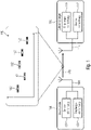
- the data transmitter 100 can be designed to send a signal 120, the signal 120 having at least two separate partial data packets 142.
- the data receiver 110 can be designed to receive the signal 120 (or a version of the signal 120 modified by the transmission channel)), which has the at least two separate partial data packets 142 .
- the at least two separate partial data packets 142 are separated or spaced apart from one another in terms of time and/or frequency.
- the at least two separate partial data packets 142 can be distributed in time and/or frequency according to a hopping pattern 140 .
- the data transmitter 100 can have a transmission device (or transmission module, or transmitter) 102 that is designed to transmit the signal 120 .
- the transmission device 102 can be connected to an antenna 104 of the data transmitter 100 .
- the data transmitter 100 can also have a receiving device (or receiving module, or receiver) 106 which is designed to receive a signal.
- the receiving device 106 can be connected to the antenna 104 or to a further (separate) antenna of the data transmitter 100 .
- the data transmitter 100 can also have a combined transceiver.
- the data receiver 110 can have a receiving device (or receiving module, or receiver) 116 which is designed to receive the signal 120 .
- the receiving device 116 can be connected to an antenna 114 of the data receiver 110 .
- the data receiver 110 can have a transmission device (or transmission module, or transmitter) 112 which is designed to transmit a signal.
- the transmission device 112 can be connected to the antenna 114 or to a further (separate) antenna of the data receiver 110 .
- the data receiver 110 can also have a combined transceiver.
- data transmitter 100 may be a sensor node, while data receiver 110 may be a base station.
- a communication system includes at least one data receiver 110 (base station) and a plurality of data transmitters (sensor nodes, such as heating meters).
- the data transmitter 100 is a base station
- the data receiver 110 is a sensor node.
- both the data transmitter 100 and the data receiver 110 to be sensor nodes.
- both the data transmitter 100 and the data receiver 110 to be base stations.
- the data transmitter 100 and the data receiver 110 can be designed to send or receive data using a telegram splitting method.
- a data packet (or telegram) containing the data is divided into a plurality of partial data packets (or sub-data packets) 142 and the partial data packets 142 are distributed over time according to a jump pattern 140 and/or distributed in frequency from the data transmitter 100 to the data receiver 110, the data receiver 110 reassembling (or combining) the partial data packets 142 in order to obtain the actual data packet.
- Each of the partial data packets 142 contains only part of the data packet 120.
- the data packet can also be channel-coded, so that not all partial data packets 142 but only part of the partial data packets 142 is required for error-free decoding of the data packet.
- the temporal distribution of the plurality of partial data packets 142 can take place in accordance with a time and/or frequency hopping pattern 140 .
- a time jump pattern can specify a sequence of transmission times or transmission time intervals with which the partial data packets are sent. For example, a first partial data packet can be sent at a first transmission time (or in a first transmission time slot) and a second partial data packet at a second transmission time (or in a second transmission time slot), the first transmission time and the second transmission time being different.
- the time jump pattern can define (or specify, or specify) the first transmission time and the second transmission time.
- the time jump pattern can specify the first transmission time and a time interval between the first transmission time and the second transmission time.
- the time jump pattern can also indicate only the time interval between the first point in time and the second transmission point in time. There may be pauses in transmission between the partial data packets, during which no transmission takes place.
- the partial data packets can also overlap (overlap) in time.
- a frequency hopping pattern can specify a sequence of transmission frequencies or transmission frequency hops with which the partial data packets are transmitted. For example, a first partial data packet can be sent at a first transmission frequency (or in a first frequency channel) and a second partial data packet can be sent at a second transmission frequency (or in a second frequency channel), with the first transmission frequency and the second transmission frequency being different.
- the frequency hopping pattern can define (or specify, or specify) the first transmission frequency and the second transmission frequency.
- the frequency hopping pattern may indicate the first transmission frequency and a frequency spacing (transmission frequency hop) between the first transmission frequency and the second transmission frequency.
- the frequency hopping pattern can also indicate only the frequency spacing (transmission frequency hopping) between the first transmission frequency and the second transmission frequency.
- the plurality of partial data packets 142 can also be distributed from the data transmitter 100 to the data receiver 110 both in terms of time and frequency.
- the distribution of the plurality of partial data packets in time and in frequency can take place according to a time-frequency hopping pattern.
- a time-frequency hopping pattern can be the combination of a time hopping pattern and a frequency hopping pattern, i.e. a sequence of transmission times or transmission time intervals with which the partial data packets 142 are transmitted, with the transmission times (or transmission time intervals) being assigned transmission frequencies (or transmission frequency hops).
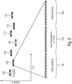
- 2 1 shows in a diagram an occupancy of the transmission channel during the transmission of a plurality of partial data packets 142 in accordance with a time-frequency hopping pattern.
- the ordinate describes the frequency and the abscissa describes the time.
- the plurality of sub-data packets 142 can, in addition to data (data symbols 146 in 2 ) also pilot sequences (pilot symbols (or synchronization symbols) 144 in 2 ) included, based on which the data receiver 110 detect the partial data packets 142 in a received signal 120 or received data stream.
- the partial data packets are detected and decoded separately or separately from one another, as will be explained below.
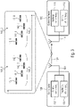
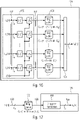
- FIG. 3 shows a schematic block diagram of a system with a data transmitter 100 and a data receiver 110.
- the data transmitter 100 is designed to send a signal 120 to send, which has a large number of partial data packets 142_1 to 142_8, with at least two groups 148_1 and 148_2 of partial data packets 142_1 to 142_8 in groups having the same relative group hopping pattern 140_1 and 140_2.
- a first group 148_1 of partial data packets (eg partial data packets 142_1 to 142_4) and a second group 148_2 of partial data packets (eg partial data packets 142_5 to 124_8) have the same relative group hopping pattern 140_1 and 140_2.
- the second group hopping pattern 140_2 may be a time and/or frequency shifted version of the first group hopping pattern 140_1.
- the data receiver 110 can be configured to receive the signal 120 (or a version of the signal 120 modified by a transmission channel between the data transmitter 100 and the data receiver 110), the signal 120 having a multiplicity of partial data packets 142_1 to 142_8, with at least two groups 148_1 and 148_2 of partial data packets 142_1 to 142_8 have the same relative group jump pattern 140_1 and 140_2 in groups.
- the partial data packets 142_1 to 142_8 are transmitted using at least two frequency and time hopping patterns (ie combined frequency hopping patterns and time hopping patterns) 140_1 and 140_2.
- the partial data packets 142_1 to 142_8 can also only be transmitted using pure frequency hopping patterns or time hopping patterns.
- the second group hopping pattern 140_2 may be a time-shifted version of the first group hopping pattern 140_1.
- the second group hopping pattern 140_2 can also be a frequency-shifted version of the first group hopping pattern 140_1.
- the second group hopping pattern 140_2 can also be a time and frequency shifted version of the first group hopping pattern 140_1.
- a number n of partial data packets can be an integer multiple of a number m of time hopping patterns and/or frequency hopping patterns, so that the partial data packets can be divided evenly among the number m of time hopping patterns and/or frequency hopping patterns, with the Number n of partial data packets 142_1 to 142_n is at least twice as large as the number m of time hopping patterns and/or frequency hopping patterns 140_1 to 140_m, so that at least two partial data packets are transmitted in each time hopping pattern and/or frequency hopping pattern 140_1 to 140_m.
- the data can be transmitted in such a way that there are transmission pauses (pauses in which the data transmitter is not transmitting) between the partial data packets 142_1 to 142_n.
- the data can be a telegram that is divided into the plurality of partial data packets 142_1 to 142_m, each of the plurality of partial data packets 142_1 to 142_m being shorter than the telegram.
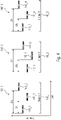
- FIG. 4 shows in a diagram an occupancy of a transmission channel when transmitting a large number of partial data packets 142_1 to 142_n, three groups of partial data packets of the large number of partial data packets having the same relative group hopping pattern 140_1, 140_2 and 140__3 in groups.
- nine partial data packets 142_1 to 142_9 can be divided into three groups 148_1 to 148_3, so that each of the three groups 148_1 to 148_3 includes three of the partial data packets 142_1 to 142_9.
- the second group hopping pattern 140_2 can be a time and frequency shifted version of the first group hopping pattern 140_1, while the third group hopping pattern 140_3 can be a time and frequency shifted version of the first group hopping pattern 140_1.
- the time intervals ⁇ x1 and ⁇ x2 and the frequency intervals between the partial data packets are the same in the three group hopping patterns 140_1 to 140_3.
- the partial data packets 142_1 to 142_9 or at least part of the partial data packets can be provided with synchronization sequences or partial synchronization sequences (split synchronization sequence) for synchronization and/or detection at the data receiver.
- 4 shows a subdivision of partial data packets 142_1 to 142_n into groups 148_1 to 148_m. 4 shows this method as an example for nine partial data packets 142_1 to 142_9 which were combined into three groups 148_1 to 148_3 with the size of three partial data packets.
- the group hopping pattern is the same for time and/or frequency. The pauses and frequencies can be different between the groups 148_1 to 148_3.
- a multi-stage correlation for the detection of the partial data packets 142 takes place in exemplary embodiments, as will be explained below.
- Figure 5a shows a schematic block diagram of a data receiver 110 according to an embodiment.
- the data receiver 110 can be designed to receive a signal 120 which has a plurality of partial data packets 142 which are distributed in time and frequency, for example according to a hopping pattern, the plurality of partial data packets 142 each having a part of a data packet .
- the data receiver 110 (or a packet detector of the data receiver 110) can have a multi-stage correlator 122, which can be designed to carry out a multi-stage correlation in order to detect the partial data packets 142 in the received signal 121, wherein a second correlation stage 128 of the multi-stage correlator 122 based on correlation results 125 of a first correlation stage 124 of the multi-stage correlator 122 operates.
- the multi-stage correlator 122 can be configured to detect the partial data packets 142 based on preambles thereof in the received signal 121 .
- the multi-stage correlator 122 can be designed to detect the partial data packets 142 using a blind estimation method.
- Figure 5b shows a schematic block diagram of a data receiver 110 according to a further embodiment of the present invention.
- the data receiver 110 can be designed to receive a signal 120 having a plurality of partial data packets 142 which are distributed, for example, according to a hopping pattern in time and frequency, the plurality of partial data packets 142 each having a part of a data packet.
- the data receiver 110 (or a packet detector of the data receiver 110) can have a multi-stage correlator 122 which can be designed to carry out a multi-stage correlation in order to detect the partial data packets 142 in the received signal 121.
- the multi-stage correlator 122 can have a first correlation stage 124, a second correlation stage 128 and a third correlation stage 129, with the second correlation stage 128 working based on correlation results 125 of the first correlation stage 124, with the third correlation stage 129 working based on correlation results 126 of the second correlation stage 128 .
- Embodiments relate to a preamble correlation and the detection of data packets in the receiver 110 of a radio transmission system.
- the German-language term "preamble" for the symbols used for correlation is used here independently of the arrangement of the preamble within the data packets and therefore includes the cases referred to in the English-language literature as preamble , midamble and postamble .
- the method is explained below using the example of a preamble arranged exactly in the middle, but it applies to other arrangements in the same way.
- the packet detector 130 can have an (optional) filter bank (e.g. a matched filter bank) 132, the multi-stage correlator 122 with the first correlation stage (e.g. preamble correlation) 124 and further correlation stages (e.g. sequence correlation) 127, and a packet Detection 134 have.
- the further correlation stages 127 are composed either of a second correlation stage 128 according to Figure 5a or a second 128 and a third 129 correlation stage according to Figure 5b together.
- the preamble correlation 124 and the sequence correlation 127 form the packet correlator 122.
- the received signal 121 may have a plurality of channels.
- the data receiver 110 may include the filter bank 132 to, based on the signal 120 (e.g., a broadband signal in 6 ) to obtain a received signal 121 (e.g. signal to be processed) with a plurality of channels.
- the data receiver 110 can also have a group of narrowband receivers in order to obtain a received signal 121 with a plurality of channels based on the signal 120.
- the reception frequencies of the plurality of narrowband receivers can be adjusted in such a way that the same signals result as at the output of the 6 shown filter bank 132.
- the plurality of channels of the received signal 121 are referred to as sub-band signals.
- the subband signals can have different bands of the signal 120, how these are obtained is irrelevant.
- 7 shows in a diagram an occupancy of the transmission channel when transmitting data packets using four different transmission methods. It describes in 7 the ordinate the frequency and the abscissa the time. In other words, 7 shows four possible methods for transmitting a single packet,
- a first transmission method (case 1) comprises a continuous transmission of a data packet at a constant frequency.
- a second transmission method (case 2) comprises a continuous transmission of a data packet in connection with a frequency hopping method.
- a third transmission method (case 3) includes discontinuous transmission of a data packet (telegram splitting) at a constant frequency.
- a fourth transmission method (case 4) includes a discontinuous transmission of a data packet (telegram splitting) in connection with a frequency hopping method.
- Embodiments of the data receiver 110 are relevant to all four methods when a large number of data packets are to be received, when the data receiver 110 has to receive a large number of data packets which are transmitted asynchronously from different data transmitters 100 and on different frequencies within an assigned frequency band.
- the broadband signal 120 has a significantly higher bandwidth at the input than the partial data packets 142.
- each partial data packet 142 contains its own preamble.
- the sequence of the partial data packets 142 in terms of time and frequency is referred to below as a (partial data packet) sequence.
- the throughput of the transmission system can be further increased by using different data transmitters 100 different sequences; as a result, the probability of collisions of the partial data packets 142 from different data transmitters 100 decreases.
- frequency generators with a relatively high tolerance are used in the data transmitters 100 for cost reasons.
- a frequency offset occurs between data transmitter 100 and data receiver 110, which can be a multiple of the symbol rate f sym of the partial data packets. Since this effect also reduces the probability of packet collisions, the maximum throughput of the transmission system can be further increased by adding a stochastic component to the transmission frequencies. As a result, the transmission frequencies in the data receiver 110 are in principle unknown.
- the data packets can be detected in the data receiver with the aid of the preambles in the partial data packets 142 .
- the assigned frequency band can be broken down into overlapping channels to be processed in parallel using a filter bank (eg matched filter bank) 132; in this case, the distances ⁇ f MF between the center frequencies of the individual channels can only be a fraction of the symbol rate f sym of the partial data packets 142 .
- the partial data packet 142 may include N P preamble symbols 144 and N D data symbols 146, where the preamble may be centered.
- a data packet can consist of M partial data packets 142 that are transmitted discontinuously.
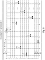
- 9 shows in a diagram the temporal and frequency arrangement of the partial data packets 142 of a data packet in the assigned frequency band with the bandwidth B. The ordinate describes the frequency and the abscissa describes the time.
- the M points in time [t 1 , t 2 , . . . , t M ] and the N carrier frequencies [f 1 , f 2 , . . . , f N ] can be chosen freely. In practice, however, an equidistant grid with the increment ⁇ f T can be used for the frequencies, for example, since this facilitates signal generation in the data transmitter 100 . In contrast, the points in time are not equidistant.
- the number N of carrier frequencies can be less than or equal to the number M of partial data packets 142 . If N ⁇ M, individual carrier frequencies are used several times. However, this is not a general restriction; the number N of carrier frequencies can also be greater than the number M of partial data packets 142 . In this case, not all carriers are occupied during a transmission.
- the distance f off between the lower end of the frequency band and the frequency f 1 is variable due to the imprecise frequency generation in the data transmitters and the aforementioned stochastic component in the transmission frequencies and can, for example, correspond to at least half the bandwidth B T of a partial data packet 142, so that the partial data packet with the carrier frequency f 1 is still completely within the frequency band.
- the sequence Sp of a data packet can be defined, for example, by the sequence of indices of the frequencies with regard to the times [t 1 , t 2 , . . . , t M ].
- S P 7 , 10 , 1 , 5 , N , 12 , 4 , 8th , ... , 11
- the packet correlator (multi-stage correlator) 122 requires a lot of computing power.
- the M G indices of the group S G can assume values in the range [1, . . . , N ⁇ X].
- the N G values of the group sequence S PG can then assume values in the range [0, ... , X], so that the addition of any value from the group S G and any value from the group sequence S PG always results in a value in the range [1, ... , N] yields.
- M G ⁇ N G can apply, ie the length of a group can be less than the number of groups. In this case, the computational effort decreases as the value of X decreases.
- an integer value can be selected for M ⁇ so that the frequency generation in the transmitters and receivers can be designed as simply as possible.
- group sequence correlation N S -fold occurs in parallel.
- a lower value for the parameter X leads to a particularly pronounced reduction in the computational effort.
- 10 12 shows a schematic block diagram of a first correlation stage 124 of the multi-stage correlator 122 of the data receiver 110, according to an embodiment.
- P sub-band signals can be present at the input of the first correlation stage, wherein the first correlation stage 124 can be designed to correlate a sub-band signal (e.g. the sub-band signal 121_1) of P sub-band signals in the preamble section correlation 150 with the K preamble sections in order to obtain K section correlation results 152 (eg, bin correlation amplitudes) for the subband signal (eg, subband signal 121_1), and to combine 154 the K bin correlation results 152 to obtain a set of correlation results 156 for the subband signal (eg, subband signal 121_1).
- K section correlation results 152 eg, bin correlation amplitudes
- the first correlation stage 124 can be configured to correlate at least two sub-band signals of the P sub-band signals (e.g. several sub-band signals of the P sub-band signals or all sub-band signals of the P sub-band signals) with the K sub-preambles in order to generate one for each sub-band signal of the at least two sub-band signals subset of correlation results 158 (e.g. a one-dimensional array of (normalized) correlation amplitudes), wherein the first correlation stage 124 can be designed to provide a first set of correlation results 156 as correlation results 125 of the first correlation stage, which has the subsets of correlation results 158, for example, the first set of correlation results 156 may include the one-dimensional subsets of correlation results 158.
- the first correlation stage 124 can be designed to provide a first set of correlation results 156 as correlation results 125 of the first correlation stage, which has the subsets of correlation results 158, for example, the first set of correlation results 156 may include the one-dimensional subsets of correlation results
- the first set of correlation results 156 of the first correlation stage 124 can thus be a two-dimensional array of correlation results, with a first dimension of the two-dimensional array of correlation results describing (e.g. a sequence of) sampling times of the subband signals, with a second dimension of the two-dimensional array of correlation results describing the majority described by subbands.
- 11 12 shows a schematic block diagram of the second correlation stage 128 of the multi-stage correlator of the data receiver 110, according to an embodiment.
- At least two groups of partial data packets 148_1 and 148_2 can have the same relative group hopping pattern 140_1, 140_2 in groups, for example so that partial data packets 142 of a first group of partial data packets have the same relative group hopping pattern as partial data packets 142 of a second group of partial data packets 148_2 (cf. 3 ).
- the second correlation stage 128 can be configured to derive from the first set of correlation results 156 (e.g. the two-dimensional array of correlation results) of the first correlation stage 124 groups of correlation results 160 based on a group correlation pattern 162 which is derived from the group hopping pattern 140_1, 140_2 , select and combine 164 (e.g. add) in groups to obtain a second set of correlation results 166 of the second correlation stage 128.
- first set of correlation results 156 e.g. the two-dimensional array of correlation results
- select and combine 164 e.g. add
- the group correlation pattern 162 can indicate time and frequency intervals of the correlation results of the two-dimensional array of correlation results 156 of the first correlation stage 124, which correspond to the relative time and frequency intervals of the group hopping pattern 140_1, 140_2 of the groups of partial data packets 142.
- the second correlation stage 128 can be designed to select the groups of correlation results 160 from the first set of correlation results 156 of the first correlation stage 124 in the time and/or frequency direction based on the group correlation pattern 162 .
- the second set of correlation results 166 of the second correlation stage 128 can be a two-dimensional array of correlation results, with a first dimension of the two-dimensional array of correlation results 166 describing a position in time of the group of partial data packets 142, with a second dimension of the two-dimensional array of correlation results 166 describes a frequency position of the group of partial data packets 142 .
- the third correlation stage can essentially correspond to the second correlation stage 128, with the difference that the third correlation stage groups correlation results of the second correlation stage based on a group sequence correlation pattern instead of a group correlation pattern, with the group sequence hopping pattern having relative time and frequency intervals between the groups of partial data packets 148_1 and 148_2 (cf. 3 ) indicates.
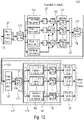
- the multi-stage correlator 122 comprises three correlation stages, in detail a first correlation stage 124 (cf. 10 ), a second correlation stage 128 (cf. 11 ) and a third correlation stage 129.
- the first correlation stage 124 can assume a preamble correlation
- the second (128) and the third (129) correlation stage can assume a sequence correlation (127).
- the input signal 121 of the multi-stage correlator 122 can comprise P subband signals.
- the P subband signals can be obtained by the filter bank (e.g. matched filter) 132, for example.
- the P subband signals present at the input of the multi-stage correlator 122 are on the broadband signal 120 (see 6 ) are based, but it is irrelevant how the broadband signal 120 which is present at the antenna of the data receiver 110 (eg "in the air") is broken down into the P sub-band signals. This can be done, for example, with the in 12 shown filter bank 132, but just as well with P narrowband receivers or a wideband receiver and a different type of decomposition.
- the multi-stage correlator 122 may include a first latch (e.g., ring buffer) 170, which may be configured to latch the P subband signals (e.g., provided by the filter bank 132).
- a first latch e.g., ring buffer 170
- P subband signals e.g., provided by the filter bank 132
- the first correlation stage 124 can be designed to correlate the P subband signals into which the broadband signal 120 is broken down, respectively with the K preamble sections in the preamble section correlation 150 in order to obtain K section correlation results 152 (e.g. section correlation amplitudes) for the respective subband signal. Furthermore, the first correlation stage 124 can be designed to normalize the K section correlation results 152 as a function of an ascertained power p[n] (eg calculated over a plurality of sub-bands). For example, the first correlation stage 124 can be designed to normalize the section correlation results 152 by forming the squares of absolute values, dividing by the determined power p[n] and calculating the roots of the quotients.
- the first correlation stage 124 can have K queue buffers (eg ring buffers) 153, which can be designed to buffer the respective section correlation results 152, the plurality of queue buffers 153 being different Can have memory lengths, wherein the memory lengths of the K buffer queues 153 can be dependent on the respective preamble sections of the preambles of the partial data packets 142 .
- the first correlation stage 124 can be designed to combine (e.g. add) the K section correlation results 152 temporarily stored in the K queue buffers 153 in order to obtain a subset of correlation results 158 for each of the subband signals, and to obtain a first set of correlation results 156, comprising the subsets of correlation results 158 for the P subbands.
- the first correlation stage 124 can also have a (eg two-dimensional) output queue buffer (eg ring buffer) 172 which can be designed to temporarily store the first set of correlation results 156 of the first correlation stage 124 .
- the second correlation stage 128 can have a group correlation 165, which can be designed to select groups of correlation results based on a group correlation pattern from the first set of correlation results 156' of the first correlation stage 124 temporarily stored in the output queue buffer (e.g. ring buffer) 172 and combine (e.g. add) in groups to obtain a second set of correlation results 166.
- the second correlation stage 128 may include a (e.g., two-dimensional) output queue buffer (e.g., ring buffer) 174, which may be configured to buffer the second set of correlation results 166 of the second correlation stage 128.
- the third correlation stage 129 can have a group sequence correlation 180, which can be designed to select groups of correlation results based on a group sequence correlation pattern from the second set of correlation results 166' of the second correlation stage 128 temporarily stored in the output queue buffer (e.g. ring buffer) 174 and to assign them by group combine (eg, add) to obtain a third set of correlation results 182 .
- the third correlation stage 129 can have a (eg two-dimensional) output queue buffer (eg ring buffer) 176 which can be designed to temporarily store the third set of correlation results 182 of the third correlation stage 129 .
- the third correlation stage 129 can be designed to provide the correlation results in a form suitable for subsequent packet detection 134 .
- the third correlation stage can be designed to detect N S sequences of partial data packets.
- the group sequence correlation 180, the output queue buffer 176 and the packet detection N s -fold can be implemented for this purpose.
- Ring buffers for storing the intermediate results are arranged between the individual processing blocks.
- the depth of this ring buffer is given by the processing length of the subsequent processing block.
- the preamble can be divided into K sections of length L K , each of which is standardized individually and then added.
- the sections can be chosen to be overlapping or non-overlapping.
- a value in the range 1 . . . L K can be selected for the displacement D K between the individual sections.
- D K L K one obtains non-overlapping sections.
- N P preamble symbols
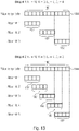
- FIG. 12 shows a schematic view of an example division of a preamble 190, according to an embodiment.
- the preamble 190 includes 12 preamble symbols 144, with a first example dividing the preamble 190 into three non-overlapping sections 192 of four preamble symbols 144 each, and a second example dividing the preamble 190 into five overlapping sections 192 of four preamble symbols 144 each will.
- the immunity to pulsed interference can be significantly improved.
- the division allows a reduction in the number CP of channels to be processed in parallel (eg by reducing the overlapping of the subband signals, ie by reducing the oversampling M F in the frequency direction).
- the result of the preamble correlation 124 is normalized, real-valued correlation amplitudes, which result from the addition of the corresponding values of the individual sections.
- the results of the individual sections can be shifted in time by appropriate selection of the depths of the ring buffers following the normalization. Since the correlation takes place exclusively in the time direction, the number C P of channels remains unchanged.
- the normalized correlation amplitudes of the M G preambles of the partial data packets 142 of a group can be added in the group correlation 128 . This can be done by means of the temporal structure described by T G and the frequency structure of a group described by S G . Since the correlation also occurs here in the frequency direction, the number of channels is reduced from C P to C G .
- the normalized correlation amplitudes of the N G groups in a sequence can be added in the group sequence correlation. This can be done by means of the temporal structure described by T PG,i and the frequency structure of the respective group sequence described by S PG,i . Since there is also a correlation in the frequency direction here, the number of channels is reduced from C G to C S .
- the number of channels in the preamble correlation can correspond to the number of relevant channels (subband signals), e.g. the relevant channels of a matched filter bank:
- M F is the oversampling factor in the frequency direction.
- the factor M F can be adjusted to the length L K of the sections of the preamble correlation.
- M f ⁇ 2 ⁇ L K are valid.
- C G M f ⁇ B ⁇ B T ⁇ B G / f sym
- B G B G
- standard ⁇ ⁇ f T B G
- C S M f ⁇ B ⁇ B T ⁇ B G ⁇ B PG / f sym
- Table 1 contains the parameter values for two examples. With regard to the structure of a data packet, the two examples differ only in the carrier spacing ⁇ f T . In both examples, the relative bandwidth of a group was chosen in such a way that the number of channels is significantly reduced by the group correlation. This is particularly important in example 2.
- parameter symbol example 1 example 2 bandwidth of the band B 100kHz 725kHz Bandwidth of a partial packet B T 5kHz 5kHz symbol rate f symbol 2.5 kBd 2.5 kBd Relative spacing of the carrier frequencies M ⁇ 1 12 Spacing of the carrier frequencies ⁇ f T 2.5kHz 30kHz Oversampling in frequency direction MF 8th 8th Number of carrier frequencies N 24 24 Normalized bandwidth of a group B G, norm 16 16 Standard. bandwidth of a group sequence B PG, norm 7 7 Number of channels in the preamble correlation CP 304 2304 Number of channels by group correlation C G 176 768 Number of channels after group sequence corr. C S 120 96 Variation range of the carrier frequencies ⁇ f off 37.5kHz 30kHz
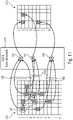
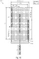
- 14 shows a schematic block diagram of a section of in 12 shown first correlation stage 124 and the provision of the subband signals upstream of the first correlation stage 124, which takes place here by way of example with a filter bank (e.g. matched filter bank) 132, and the buffer (e.g. ring buffer) 170, according to an exemplary embodiment.
- 14 Figure 12 shows the signals and ring buffer 170 of the preamble section correlation 150.
- the ring buffer 170 may have the size C P x (M T x L K ).
- FIG. 12 shows a schematic view of the preamble section correlation of the subband signals temporarily stored in the ring buffer performed by the first correlation stage, including the combination of the section correlation results, according to an embodiment.
- each MT consecutive column of the ring buffer can be combined into a column with MT ⁇ CP elements.
- the ring buffer 170 then has the size (MT * C P ) * LK .
- the correlation can now take place in parallel via M T ⁇ C P channels and supply output values for each channel M T .
- MT samples of the subband signals which can correspond, for example, to MT output vectors of a matched filter bank, can be combined to form a column in the ring buffer.
- the values of the ring buffer can be stored in the memory in columns, ie starting with the values in the first column and ending with the values in the last column.
- the variants C P ⁇ (M T * LK ) and (M T * C P ) ⁇ LK are equivalent in memory.
- the power calculation 151 shown follows the same sequence, but instead of multiplying with the reference symbols, the square of the values is calculated.
- the first correlation stage 124 can be designed to carry out normalization 155 of the section correlation results 152 in order to obtain normalized section correlation results 152′. Furthermore, the first correlation stage 124 can be designed to temporarily store the normalized section correlation results 152′ in the buffer queues 153 and to combine 154 (eg add) the normalized section correlation results 152′ buffered in the buffer queues 153 .
- 16 shows the normalization 155 and the subsequent addition of the results of the sections.
- ring buffers 153 can be used as delay elements in order to delay the results according to the time structure of the sections.
- 17 12 shows a schematic block diagram of the second correlation stage 128 of the multi-stage correlator 122 of the data receiver, according to an embodiment.
- the second correlation stage 128 can be designed to perform a group correlation 165 of the first set of correlation results 156 ′ temporarily stored in the output queue buffer (e.g. ring buffer) 172 of the first correlation stage 124 in order to obtain a second set of correlation results 166 .
- 17 shows the signals and the ring buffer of the group correlation.
- FIG. 18 shows a schematic view of a two-dimensional memory structure of the output queue buffer (e.g. ring buffer) 172 of the first correlation stage 124 and the group correlation 165 carried out by the second correlation stage 128, in which from the first set of correlation results stored in the output queue buffer (e.g. ring buffer) 172 of the first correlation stage 124 is temporarily stored, based on a group correlation pattern, groups of correlation results 160 are selected and combined 164 in groups.
- the output queue buffer e.g. ring buffer
- 18 shows the course of the group correlation 165.
- the M G sub-columns to be added each with C G values, migrate horizontally cyclically through the ring buffer.
- the number of channels is reduced from C P to C G as part of the group correlation. This reduction is all the greater, the greater the normalized bandwidth B G,norm of the group.
- the third correlation stage 129 can be designed to carry out a group sequence correlation 180 of the second set of correlation results 166 ′ temporarily stored in the output queue buffer (e.g. ring buffer) 174 of the second correlation stage 128 in order to obtain a third set of correlation results 182 .
- the third correlation stage 129 can be designed to detect N S sequences of partial data packets 142 .
- the group sequence correlation can be carried out 180 N s times.
- 19 shows the signals and the ring buffer of the group sequence correlation.
- the number of channels can be reduced from C G to C S as part of the group sequence correlation. This reduction is all the greater, the larger the normalized bandwidth B PG,norm of the group sequence is.
- the N S output signals c s,1 [n],...c S,Ns [n] form the output signals of the packet correlator.
- a number of groups can alternatively also be used. Of the in the lower part of 12 The part shown with the group correlation 165 and the subsequent group sequence correlations 180 is present several times in this case.
- L K is the length of a section of the preamble. for the inside 13
- the error in the preamble correlation acts here as a limiting factor.
- the subband signals are provided by a matched filter bank, since this is the embodiment that is preferred in practice. In principle, however, it can be provided using any method that can provide a set of subband signals that are equivalent for further processing. In other words: The way in which the subband signals are provided is not relevant for the processing.
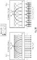
- FIG. 20 shows in detail 20 a schematic view of a reduction in the number of channels of a matched filter bank 132 from an f/8 matched filter bank 132_1 to an f/4 matched filter bank 132_2.
- every second filter of the f/8 matched filter bank can be omitted and the outputs of the resulting f/4 matched filter bank can be shifted by ⁇ f sym / 16 with two mixers each, so that a frequency grid as in of an f/8 matched filter bank.
- the computing effort in the matched filter bank 132 can be reduced by about half.
- the mixers after the f/4 matched filter bank 132_2 can be saved by using two different preambles rotated with the corresponding mixing frequencies or their sections as reference symbols in the correlation. This is in 21 shown for a single channel.
- this procedure is not equivalent with regard to the complex-valued result of the correlation, only the square of the absolute value of the result is required in further processing, so that the deviation has no effect.
- the reference symbols are rotated once during the initialization of the components.
- the number of channels at the input or in the matched filter bank 132 is halved and the number of channels after the preamble correlation is halved by maximum formation over two adjacent channels - the in 23 shown preamble correlation with reduced number of channels.
- the first correlation stage 124 is designed to shift a sub-band signal provided by the f/4 matched filter bank by means of two mixers by ⁇ f sym / 16, and to carry out a preamble section correlation 150 for the ⁇ f sym / 16-shifted versions of the sub-band signal to obtain preamble section results, and to perform a normalization 155 of the preamble section results to obtain normalized preamble section results, and to buffer the normalized preamble section results in the queue latches 153, and to combine 154 the latched normalized preamble section results to provide for the ⁇ f sym / 16 shifted versions of each sub-band signal to obtain an interim correlation result, and to carry out a maximum formation 157 of the interim correlation results in order to obtain a correlation result for each sub-band signal.
- the data sender sends out its packet at any point in time.
- the recipient has no or only imprecise knowledge of the transmission time at which the transmission begins. This point in time must be determined in the receiver by means of a detection.
- the preamble is typically divided into a number of sections by the telegram splitting method or in the case of a time or frequency hopping method.
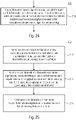
- Embodiments of the present invention take a different approach, in which the correlation is subdivided into a number of partial correlations and the partial results are then combined to form an overall result.
- a requirement of this methodology can be, for example, that the sequence is the same in all sections. If this is the case, the correlation, as described in section 2, can be divided into a preamble correlation, an (optional) group correlation and a group sequence correlation.
- This method reduces the required computing power of the detector enormously. This can either use less expensive hardware or increase the number of supported hopping patterns.
- the correlator consists not only of a single-stage correlator, there are at least two correlators, with the second correlator operating on the basis of the results of the first correlator.
- the results in the stages can be temporarily stored (e.g. in a database or a ring buffer).
- a correlation can first be carried out via the preamble sequence sections. These results can then be combined in a second correlator to form a group result. The group sequence correlation can then be carried out on the basis of the group correlation, which supplies the overall result for the detection.
- the results from the memories of the various preamble correlations can now be loaded and combined according to the hopping pattern. Further processing is analogous to the procedure described above.
- the first correlation stage has at least two parallel correlates.
- the results from the plurality of first stage correlators can be loaded and combined according to the hopping pattern.
- the post-correlation threshold can be chosen based on background noise. Due to the length of the correlation, an additional noise averaging is carried out, which limits the number of false detections with a suitable threshold value. All correlation values above the threshold value represent the beginning of a transmitted data packet with a very high probability. The higher the received power of the transmitted data packet at the data receiver, the higher the correlation value and thus the higher the probability that a data packet has been transmitted.
- non-linear function is required for normalization. This can represent, for example, the weighting of the amounts according to the estimated disturbance, as described above.
- the partial packets can be normalized to the estimated interference. This normalization can take place either before the correlation or also after the correlation.
- a more concrete example of this normalization is the normalization of the correlation results to the received signal power. For this purpose, the squares of the absolute values are formed for all symbols in the preamble and the sum is then calculated.
- the correlation result is also normalized to the received signal power. However, since the received symbols generally deviate from the expected preamble sequence during the interference, the correlation result is significantly lower than for a signal that is not disturbed.
- the normalization thus ensures that the correlation result is well below one and thus the probability of an incorrect detection decreases.
- the correlation result can also be divided directly by the square root of the determined signal power.
- the normalization can also take place before the correlation. To do this, the signal power is calculated in the same way as above and then the square root is taken. This result is applied to each input symbol using division.
- the correlation result can be normalized to the received signal power of the preamble. This can be done in several ways.
- data symbols occur before and/or after the received preamble, these data symbols can also (partially) be included in the calculation of the power.
- the number of symbols used to determine the power is greater than the number of preamble symbols used for the correlation.
- the determination of the received signal power can be performed over at least one data symbol.
- either the same number of symbols can be used as for the correlation, or neighboring symbols can be included again.
- a separate normalization of the partial areas of the correlation can be carried out.
- either a separate determination of the performance or a joint performance determination can be made for each sub-area.
- the normalization can be carried out separately for each channel. If it can be assumed that interference always occupies at least two of the channels, the power can also be determined jointly for at least two channels.
- the normalization in a multi-channel receiver, can be carried out on all channels in parallel, with the power determination also being able to take place across a number of channels.
- results from different points in time can be added depending on the time position of the sequence.
- a solution to avoid this problem is to create a buffer structure for the partial correlation results.
- n ring buffers can be used for the n partial correlations.
- the time dependency between the partial correlations can be established by the length of each ring buffer. That is, the length of the buffer determines the duration of the delay.
- the oldest entries in all ring buffers can be added up before they are discarded in the next step.
- a buffer structure can be used at the output of the partial correlations.
- the length of the respective buffer determines the time delay (see 16 ) realized.
- the frequency offset (random and/or systematic offset) between the data transmitter and data receiver can be a multiple of the symbol rate, it is necessary to use a multi-channel correlator.
- a filter bank can be used beforehand, which generates the symbols for each channel.
- this limitation applies to the multi-channel correlator and not to the previous filter bank. This is graphically in 20 illustrated using the frequency response of the filter.
- the filter bank of the multi-channel correlator can have a different frequency oversampling than the following correlator.
- the symbols of the filter bank can be multiplied by a complex exponential oscillation (corresponds to a digital frequency shift), with the selection of the exponential oscillation depending on the frequency offset.
- the reference sequence can also be multiplied by the exponential. As a result, there is then a separate reference sequence for each frequency offset, but there is no need for multiplication in each calculation step.
- a separate reference sequence can be used for each frequency line to be generated from the data of the filter bank, with the adapted reference frequency being generated from the original reference sequence by multiplication with the corresponding exponential oscillation.
- a further possibility for reducing the channels results from the finding that the high frequency resolution of the preamble correlation is not required for the subsequent group and group sequence correlation.
- the number of channels after the first correlation stage can be reduced, which entails less computing effort and smaller memories.
- a maximum formation can be carried out over adjacent channels.
- the smaller value(s) is/are discarded for further processing.
- FIG. 2 shows a flow diagram of a method 200 for receiving a signal, the signal comprising a plurality of sub-data packets [eg distributed in time and frequency according to a hopping pattern], the plurality of sub-data packets each comprising a portion of a data packet.
- the method 200 comprises a step 202 of performing a multi-stage correlation [e.g. of the received signal (e.g. in a first correlation stage) and a (e.g. by the first correlation stage) processed version of the received signal (e.g. in a second correlation stage)] in order to to detect partial data packets [e.g. based on preambles thereof] in the received signal, a second correlation stage of the multi-stage correlation being based on correlation results [e.g. based on the processed version of the received signal] of a first correlation stage of the multi-stage correlation.
- a multi-stage correlation e.g. of the received signal (e.g. in a first correlation stage) and a (e.g.
- FIG. 2 shows a flow diagram of a method 210 for receiving a signal, the signal having at least one data packet, the data packet having a preamble.
- the method 210 includes a step 212 of correlating the received signal or a version derived therefrom [e.g. a filtered and/or stored version of the received signal] with a plurality of preamble sections [e.g. which correspond to (e.g. coincide with) different (e.g. overlapping or adjoining) sections of the preamble of the data packet (e.g.
- the method 210 comprises a step 214 of normalizing the plurality of section correlation results, the plurality of section correlation results depending on a determined [e.g. calculated] power or interference power (p[n]) of the received signal or the version derived therefrom [e.g. the filtered and/or stored version of the received signal].
- a determined [e.g. calculated] power or interference power (p[n]) of the received signal or the version derived therefrom e.g. the filtered and/or stored version of the received signal].
- the method 210 comprises a step 216 of combining [eg to add or incoherently add] the plurality of normalized section correlation results [eg per sample] to form a set of correlation results [eg (normalized) correlation amplitudes; eg for the received signal].
- aspects have been described in the context of a device, it is understood that these aspects also represent a description of the corresponding method, so that a block or a component of a device is also to be understood as a corresponding method step or as a feature of a method step. Similarly, aspects described in connection with or as a method step also constitute a description of a corresponding block or detail or feature of a corresponding device.
- Some or all of the method steps may be performed by hardware apparatus (or using a hardware Apparatus), such as a microprocessor, a programmable computer, or an electronic circuit. In some embodiments, some or more of the essential process steps can be performed by such an apparatus.
- embodiments of the invention may be implemented in hardware or in software. Implementation can be performed using a digital storage medium such as a floppy disk, DVD, Blu-ray Disc, CD, ROM, PROM, EPROM, EEPROM or FLASH memory, hard disk or other magnetic or optical memory are carried out on which electronically readable control signals are stored, which can interact with a programmable computer system in such a way or work together to ensure that the respective procedure is carried out. Therefore, the digital storage medium can be computer-readable.
- a digital storage medium such as a floppy disk, DVD, Blu-ray Disc, CD, ROM, PROM, EPROM, EEPROM or FLASH memory, hard disk or other magnetic or optical memory are carried out on which electronically readable control signals are stored, which can interact with a programmable computer system in such a way or work together to ensure that the respective procedure is carried out. Therefore, the digital storage medium can be computer-readable.
- some embodiments according to the invention comprise a data carrier having electronically readable control signals capable of interacting with a programmable computer system in such a way that one of the methods described herein is carried out.
- embodiments of the present invention can be implemented as a computer program product with a program code, wherein the program code is effective to perform one of the methods when the computer program product runs on a computer.
- the program code can also be stored on a machine-readable carrier, for example.
- exemplary embodiments include the computer program for performing one of the methods described herein, the computer program being stored on a machine-readable carrier.
- an exemplary embodiment of the method according to the invention is therefore a computer program that has a program code for performing one of the methods described herein when the computer program runs on a computer.
- a further exemplary embodiment of the method according to the invention is therefore a data carrier (or a digital storage medium or a computer-readable medium) on which the computer program for carrying out one of the methods described herein is recorded.
- the data carrier, digital storage medium, or computer-readable medium is typically tangible and/or non-transitory.
- a further exemplary embodiment of the method according to the invention is thus a data stream or a sequence of signals which represents the computer program for carrying out one of the methods described herein.
- the data stream or the sequence of signals can, for example, go as follows be configured to be transferred over a data communication link, for example over the Internet.
- Another embodiment includes a processing device, such as a computer or programmable logic device, configured or adapted to perform any of the methods described herein.
- a processing device such as a computer or programmable logic device, configured or adapted to perform any of the methods described herein.
- Another embodiment includes a computer on which the computer program for performing one of the methods described herein is installed.
- a further exemplary embodiment according to the invention comprises a device or a system which is designed to transmit a computer program for carrying out at least one of the methods described herein to a recipient.
- the transmission can take place electronically or optically, for example.
- the recipient may be a computer, mobile device, storage device, or similar device.
- the device or the system can, for example, comprise a file server for transmission of the computer program to the recipient.
- a programmable logic device e.g., a field programmable gate array, an FPGA
- a field programmable gate array may cooperate with a microprocessor to perform any of the methods described herein.
- the methods are performed on the part of any hardware device. This can be hardware that can be used universally, such as a computer processor (CPU), or hardware that is specific to the method, such as an ASIC.
- the devices described herein may be implemented, for example, using hardware apparatus, or using a computer, or using a combination of hardware apparatus and a computer.
- the devices described herein, or any components of the devices described herein may be implemented at least partially in hardware and/or in software (computer program).
- the methods described herein may be implemented, for example, using hardware apparatus, or using a computer, or using a combination of hardware apparatus and a computer.
Description
Ausführungsbeispiele beziehen sich auf einen Datenempfänger und, im speziellen, auf einen Datenempfänger zum Empfangen eines Breitbandsignals, das mehrere Teil-Datenpakete aufweist, die entsprechend eines Zeitfrequenzsprungmusters in der Zeit und Frequenz verteilt sind. Manche Ausführungsbeispiele beziehen sich auf einen Paket-Korrelator für ein Funkübertragungssystem.Embodiments relate to a data receiver and, more particularly, to a data receiver for receiving a broadband signal comprising a plurality of sub-data packets distributed in time and frequency according to a time-frequency hopping pattern. Some embodiments relate to a packet correlator for a radio transmission system.
Aus [2] ist ein Telegram-Splitting basiertes Funkübertragungssystem bekannt, bei dem ein zu übertragendes Datenpaket (oder Telegramm) auf eine Mehrzahl von Teil-Datenpaketen aufgeteilt wird, wobei die Mehrzahl von Teil-Datenpaketen jeweils kürzer sind als das Datenpaket, und wobei die Mehrzahl von Teil-Datenpaketen entsprechend eines Zeitfrequenzsprungmusters in der Zeit und Frequenz verteilt übertragen werden.A telegram-splitting-based radio transmission system is known from [2], in which a data packet (or telegram) to be transmitted is divided into a plurality of partial data packets, with the plurality of partial data packets each being shorter than the data packet, and with the A plurality of partial data packets are transmitted distributed according to a time-frequency hopping pattern in time and frequency.
In [5] wird ein Übertragungsverfahren zur drahtlosen Übertragung von Daten in einem Kommunikationssystem (z. B. einem Sensornetzwerk oder Telemetriesystem) beschrieben. Die Daten umfassen Kerndaten und Erweiterungsdaten, wobei die Kerndaten codiert und verschachtelt auf eine Mehrzahl von Kernsubdatenpakete aufgeteilt werden, wobei die Erweiterungsdaten codiert und verschachtelt auf eine Mehrzahl von Erweiterungssubdatenpakete aufgeteilt werden, wobei zumindest ein Teil der in den Kernsubdatenpaketen enthaltenen Kerndaten für einen Empfang der Erweiterungsdaten oder Erweiterungsdatenpakete erforderlich ist.[5] describes a transmission method for the wireless transmission of data in a communication system (e.g. a sensor network or telemetry system). The data comprises core data and extension data, the core data being encoded and interleaved in a plurality of core sub-data packets, the extension data being encoded and interleaved in a plurality of extension sub-data packets, with at least part of the core data contained in the core sub-data packets being required for receiving the extension data or expansion data packages is required.
In [6] wird eine Synchronisierung von Zeit-Frequenz-Codes beschrieben. Hierbei wird ein Frequenzsprungmuster, das einem drahtlosen Fernkommunikationsnetzwerk mit kurzer Reichweite zugeordnet ist, identifiziert. Basierend auf dem identifizierten Frequenzsprungmuster wird ein Frequenzsprungmuster für die Kommunikation in einem lokalen drahtlosen Nahbereichskommunikationsnetz ausgewählt. Zusätzlich wird ein Timing für das ausgewählte Frequenzsprungmuster basierend auf dem identifizierten Frequenzsprungmuster-Timing ausgewählt. Ein oder mehrere Symbole, wie beispielsweise OFDM-Symbole, können gemäß dem ausgewählten Frequenzsprungmuster und dem ausgewählten Zeitpunkt übertragen werden.Synchronization of time-frequency codes is described in [6]. Here, a frequency hopping pattern associated with a short-range wireless long-distance communication network is identified. Based on the identified frequency hopping pattern, a frequency hopping pattern is selected for communication in a local short-range wireless communication network. Additionally, a timing for the selected frequency hopping pattern is selected based on the identified frequency hopping pattern timing. One or more symbols, such as OFDM symbols, may be transmitted according to the selected frequency hopping pattern and timing.
In [7] wird eine Verbesserung einer Reichweite für Telegram-Splitting basierte Funkübertragungssysteme beschrieben.[7] describes an improvement in a range for telegram splitting-based radio transmission systems.
Bei der gleichzeitigen bzw. zeitlich überlappenden Aussendung einer Vielzahl von in TeilDatenpaketen aufgeteilten Datenpaketen durch eine Vielzahl von Datensendern, steigt die im Datenempfänger erforderliche Rechenleistung zur Detektion der Teil-Datenpakete erheblich.With the simultaneous or temporally overlapping transmission of a large number of data packets divided into partial data packets by a large number of data transmitters, the computing power required in the data receiver for detecting the partial data packets increases considerably.
Der vorliegenden Erfindung liegt die Aufgabe zugrunde, die im Datenempfänger erforderliche Rechenleistung für die Detektion von Teil-Datenpaketen zu reduzieren.The object of the present invention is to reduce the computing power required in the data receiver for the detection of partial data packets.
Diese Aufgabe wird durch die unabhängigen Patentansprüche gelöst.This object is solved by the independent patent claims.
Vorteilhafte Weiterbildungen finden sich in den abhängigen Patentansprüchen.Advantageous developments can be found in the dependent patent claims.
Ausführungsbeispiele schaffen einen Datenempfänger, wobei der Datenempfänger ausgebildet ist, um ein Signal zu empfangen, das eine Mehrzahl von Teil-Datenpaketen aufweist [z.B. die entsprechend eines Sprungmusters in der Zeit- und Frequenz verteilt sind], wobei die Mehrzahl von Teil-Datenpaketen jeweils einen Teil eines Datenpakets aufweisen, wobei der Datenempfänger einen mehrstufigen Korrelator aufweist, der ausgebildet ist, um eine mehrstufige Korrelation [z.B. des empfangenen Signals (z.B. in einer ersten Korrelationsstufe) und einer (z.B. durch die erste Korrelationsstufe) aufbereiteten Version des empfangenen Signals (z.B. in einer zweiten Korrelationsstufe)] durchzuführen, um die TeilDatenpakete [z.B. basierend auf Präambeln derselben oder mittels eines blinden Schätzverfahrens] in dem empfangenen Signal zu detektieren, wobei eine zweite Korrelationsstufe des mehrstufigen Korrelators basierend auf Korrelationsergebnissen [z.B. basierend auf der aufbereiteten Version des empfangenen Signals] einer ersten Korrelationsstufe des mehrstufigen Korrelators arbeitet.Embodiments provide a data receiver, wherein the data receiver is configured to receive a signal having a plurality of partial data packets [e.g. distributed according to a hopping pattern in time and frequency], the plurality of partial data packets each having a Have part of a data packet, wherein the data receiver has a multi-stage correlator which is designed to carry out a multi-stage correlation [e.g. of the received signal (e.g. in a first correlation stage) and a (e.g. by the first correlation stage) processed version of the received signal (e.g. in a second correlation stage)] to carry out the partial data packets [e.g. based on preambles thereof or by means of a blind estimation method] in the received signal, wherein a second correlation stage of the multi-stage correlator operates based on correlation results [e.g. based on the conditioned version of the received signal] of a first correlation stage of the multi-stage correlator.
Bei Ausführungsbeispielen kann der mehrstufige Korrelator ausgebildet sein, um die Mehrzahl von Teil-Datenpaketen basierend auf Präambeln derselben in dem empfangenen Signal zu detektieren.In embodiments, the multi-stage correlator may be configured to detect the plurality of partial data packets based on preambles thereof in the received signal.
Bei Ausführungsbeispielen können die Mehrzahl von Teil-Datenpaketen entsprechend eines Sprungmusters in der Zeit- und Frequenz verteilt sein, wobei der mehrstufige Korrelator ausgebildet ist, um die Mehrzahl von Teil-Datenpaketen [z.B. basierend auf Präambeln derselben] in dem empfangenen Signal oder einer davon abgeleiteten Version [z.B. einer Mehrzahl von Teilbandsignalen] zu detektieren.In exemplary embodiments, the plurality of sub-data packets can be distributed in time and frequency according to a hopping pattern, with the multi-stage correlator being configured to correlate the plurality of sub-data packets [e.g. based on preambles thereof] in the received signal or a derivative thereof [e.g. a plurality of subband signals].
Bei Ausführungsbeispielen kann das empfangene Signal eine Mehrzahl von Teilbandsignalen aufweisen, wobei die Mehrzahl von Teilbandsignalen unterschiedliche [z.B. sich teilweise überlappende] Teilbänder des Signals [z.B. Breitbandsignals] aufweisen [Beispielsweise kann der Datenempfänger ausgebildet sein, um basierend auf dem Signal (z.B. Breitbandsignale) ein empfangenes Signal zu erhalten, das die Mehrzahl von Teilbandsignalen aufweist].In embodiments, the received signal may include a plurality of sub-band signals, the plurality of sub-band signals having different [e.g. partially overlapping] sub-bands of the signal [e.g. broadband signal] [For example, the data receiver may be configured to obtain a received signal comprising the plurality of subband signals based on the signal (e.g., broadband signals)].
Bei Ausführungsbeispielen können die Mehrzahl von Teilbandsignalen direkt für die durch den mehrstufigen Korrelator durchgeführte Korrelation eingesetzt werden.In embodiments, the plurality of sub-band signals can be used directly for the correlation performed by the multi-stage correlator.
Bei Ausführungsbeispielen kann der mehrstufige Korrelator ausgebildet sein, um eine mehrstufige Korrelation von zumindest einer Teilmenge der Mehrzahl von Teilbandsignalen durchzuführen, um die Mehrzahl von Teildatenpaketen in der Teilmenge der Mehrzahl von Teilbandsignalen zu detektieren [Beispielsweise kann eine Anzahl der bereitgestellten Teilbandsignale und/oder deren Abtastrate nicht mit den entsprechenden Werten des mehrstufigen Korrelators übereinstimmen, so dass der mehrstufige Korrelator nur einen Teil der Mehrzahl von Teilbandsignale und/oder nur einen Teil der Abtastwerte verarbeitet].In exemplary embodiments, the multi-stage correlator can be designed to carry out a multi-stage correlation of at least a subset of the plurality of sub-band signals in order to detect the plurality of sub-data packets in the sub-set of the plurality of sub-band signals [for example, a number of the sub-band signals provided and/or their sampling rate do not match the corresponding values of the multi-level correlator, so that the multi-level correlator processes only part of the plurality of subband signals and/or only part of the samples].
Bei Ausführungsbeispielen kann der Datenempfänger ausgebildet sein, um die Mehrzahl von Teilbandsignalen mit einer komplexen Exponentialschwingung zu multiplizieren, um die Frequenzauflösung im mehrstufigen Korrelator zu erhöhen.In embodiments, the data receiver may be configured to multiply the plurality of sub-band signals by a complex exponential to increase the frequency resolution in the multi-stage correlator.
Bei Ausführungsbeispielen kann der mehrstufige Korrelator eine erste Korrelationsstufe aufweisen, die ausgebildet sein kann, um das empfangene Signal oder eine davon abgeleitete Version [z.B. eine gefilterte und/oder gespeicherte Version des zu empfangenen Signals (z.B. ein Teilbandsignal der Mehrzahl von Teilbandsignalen)] mit einer Mehrzahl von Präambelabschnitten zu korrelieren, die mit unterschiedlichen [z.B. sich überlappenden oder aneinander angrenzenden] Abschnitten der Präambeln der Mehrzahl von Teil-Datenpaketen korrespondieren [z.B. übereinstimmen (z.B. bei einem ungestörten Übertragungskanal)], um eine Mehrzahl von Abschnittskorrelationsergebnissen [z.B. Abschnittskorrelationsamplituden; z.B. ein Abschnittskorrelationsergebnis (z.B. eine Korrelationsamplitude) pro Präambelabschnitt pro Abtastwert] zu erhalten, wobei die erste Korrelationsstufe ausgebildet ist, um die Mehrzahl von Abschnittskorrelationsergebnissen [z.B. pro Abtastwert] zu kombinieren [z.B. zu addieren oder inkohärent zu addieren (z.B. durch Betragsbildung)], um einen Satz von Korrelationsergebnissen [z.B. (normierte) Korrelationsamplituden; z.B. für das zu empfangene Signal] oder einen Teilsatz von Korrelationsergebnissen [z.B. (normierte) Korrelationsamplituden oder ein eindimensionales Array von (normierten) Korrelationsamplituden; z.B. für das Teilbandsignal der Mehrzahl von Teilbandsignalen des empfangenen Signals] der ersten Korrelationsstufe als Korrelationsergebnisse der ersten Korrelationsstufe zu erhalten.In embodiments, the multi-stage correlator may include a first correlation stage, which may be configured to correlate the received signal or a derivative thereof [e.g. to correlate a filtered and/or stored version of the signal to be received (e.g. a sub-band signal of the plurality of sub-band signals)] with a plurality of preamble sections associated with different [e.g. [e.g. overlapping or contiguous] sections of the preambles of the plurality of sub-data packets. agree (e.g. with an undisturbed transmission channel)] to obtain a plurality of section correlation results [e.g. intercept correlation amplitudes; e.g. one bin correlation result (e.g. a correlation amplitude) per preamble bin per sample], wherein the first correlation stage is adapted to obtain the plurality of bin correlation results [e.g. per sample] to combine [e.g. to add or to add incoherently (e.g. by absolute value formation)] to obtain a set of correlation results [e.g. (normalized) correlation amplitudes; e.g. for the signal to be received] or a subset of correlation results [e.g. (normalized) correlation amplitudes or a one-dimensional array of (normalized) correlation amplitudes; e.g. for the sub-band signal of the plurality of sub-band signals of the received signal] of the first correlation stage as correlation results of the first correlation stage.
Bei Ausführungsbeispielen kann die erste Korrelationsstufe ausgebildet sein, um die Mehrzahl von Abschnittskorrelationsergebnissen zu normieren [z.B. durch Bildung von Betragsquadraten].In embodiments, the first correlation stage may be configured to normalize the plurality of section correlation results [e.g. by forming absolute squares].
Bei Ausführungsbeispielen kann die erste Korrelationsstufe ausgebildet sein, um die Mehrzahl von Abschnittskorrelationsergebnissen in Abhängigkeit von einer ermittelten (z.B. berechneten) Leistung (p[n]) des empfangenen Signals oder der davon abgeleiteten Version [z.B. die gefilterte und/oder gespeicherte Version des zu empfangenen Signals (z.B. das Teilbandsignal der Mehrzahl von Teilbandsignalen)] zu normieren [Beispielsweise kann die erste Korrelationsstufe ausgebildet sein, um die Abschnittskorrelationsergebnissen durch Bildung von Betragsquadraten, Division durch die ermittelte Leistung und Berechnung der Wurzeln der Quotienten zu normieren].In exemplary embodiments, the first correlation stage can be configured to correlate the plurality of section correlation results in dependence on a determined (e.g. calculated) power (p[n]) of the received signal or the version derived therefrom [e.g. the filtered and/or stored version of the signal to be received (e.g. the sub-band signal of the plurality of sub-band signals)] [For example, the first correlation stage can be designed to normalize the section correlation results by forming the squares of the magnitude, dividing by the determined power and calculating the roots of the to normalize quotients].
Bei Ausführungsbeispielen kann die Leistung für die Normierung über mehrere Teilbänder ermittelt werden.In exemplary embodiments, the power for normalization can be determined over several sub-bands.
Bei Ausführungsbeispielen kann die Leistung für die Normierung basierend auf Synchronisationssymbolen und zumindest einem Datensymbol der jeweiligen TeilDatenpakete ermittelt werden.In exemplary embodiments, the power for the normalization can be determined based on synchronization symbols and at least one data symbol of the respective partial data packets.
Bei Ausführungsbeispielen kann die erste Korrelationsstufe ausgebildet sein, um die Mehrzahl von Abschnittskorrelationsergebnissen separat zu normieren, wobei die Leistung getrennt für jeden Präambelabschnitt oder gemeinsam für alle Präambelabschnitte ermittelt wird.In exemplary embodiments, the first correlation stage can be designed to normalize the plurality of section correlation results separately, with the power being determined separately for each preamble section or jointly for all preamble sections.
Bei Ausführungsbeispielen kann die erste Korrelationsstufe eine Mehrzahl von Warteschlangenzwischenspeichern (z.B. Ringpuffern) aufweisen, die ausgebildet sind, um die jeweiligen Abschnittskorrelationsergebnisse zwischen zu speichern, wobei die Mehrzahl von Warteschlangenzwischenspeichern unterschiedliche Speicherlängen aufweisen, wobei die Speicherlängen der Mehrzahl von Warteschlangenzwischenspeichern von den jeweiligen Präambelabschnitten der Präambeln der Mehrzahl von Teil-Datenpaketen abhängig sind.In exemplary embodiments, the first correlation stage may comprise a plurality of buffer queues (e.g. ring buffers) configured to buffer the respective section correlation results, the plurality of buffer queues having different storage lengths, the storage lengths of the plurality of buffer queues being different from the respective preamble sections of the preambles the plurality of partial data packets are dependent.
Bei Ausführungsbeispielen kann die erste Korrelationsstufe ausgebildet sein, um zumindest zwei Teilbandsignale der Mehrzahl von Teilbandsignalen [z.B. mehrere Teilbandsignale der Mehrzahl von Teilbandsignalen oder alle Teilbandsignale der Mehrzahl von Teilbandsignalen] jeweils mit der Mehrzahl von Präambelabschnitten zu korrelieren, um für jedes Teilbandsignal der zumindest zwei Teilbandsignale einen Teilsatz von Korrelationsergebnissen [z.B. (normierte) Korrelationsamplituden oder ein eindimensionales Array von (normierten) Korrelationsamplituden] zu erhalten, wobei die erste Korrelationsstufe ausgebildet ist, um als Korrelationsergebnisse der ersten Korrelationsstufe einen Satz von Korrelationsergebnissen bereitzustellen, der die Teilsätze von Korrelationsergebnissen aufweist [Beispielsweise kann der Satz von Korrelationsergebnissen die eindimensionalen Teilsätze von Korrelationsergebnissen aufweisen].In embodiments, the first correlation stage may be configured to combine at least two sub-band signals of the plurality of sub-band signals [e.g. to correlate a plurality of sub-band signals of the plurality of sub-band signals or all sub-band signals of the plurality of sub-band signals] with the plurality of preamble sections, respectively, to obtain a sub-set of correlation results [e.g. (normalized) correlation amplitudes or a one-dimensional array of (normalized) correlation amplitudes], wherein the first correlation stage is designed to provide a set of correlation results as correlation results of the first correlation stage, which has the subsets of correlation results [for example, the set of correlation results can one-dimensional subsets of correlation results].
Bei Ausführungsbeispielen kann der Satz von Korrelationsergebnissen der ersten Korrelationsstufe ein zweidimensionales Array von Korrelationsergebnissen sein, wobei eine erste Dimension des zweidimensionalen Arrays von Korrelationsergebnissen [z.B. eine Abfolge von] Abtastzeitpunkte des empfangenen Signals beschreibt [z.B. Zeitrichtung], wobei eine zweite Dimension des zweidimensionalen Arrays von Korrelationsergebnissen Teilbänder des empfangenen Signals beschreibt [z.B. Frequenzrichtung].In embodiments, the set of correlation results of the first level of correlation may be a two-dimensional array of correlation results, wherein a first dimension of the two-dimensional array of correlation results [e.g. describes a sequence of] sampling instants of the received signal [e.g. time direction], where a second dimension of the two-dimensional array of correlation results describes sub-bands of the received signal [e.g. frequency direction].
Bei Ausführungsbeispielen kann die erste Korrelationsstufe einen [z.B. mehrkanaligen] Ausgangs-Warteschlangenzwischenspeicher [z.B. Ringpuffer] aufweisen, der ausgebildet ist, um den Satz von Korrelationsergebnissen der ersten Korrelationsstufe zwischen zu speichern. Bei Ausführungsbeispielen kann die erste Korrelationsstufe ausgebildet sein, um eine Maximumbildung über Korrelationsergebnisse von benachbarten Teilbandsignalen durchzuführen, und um die kleineren Werte zu verwerfen.In exemplary embodiments, the first correlation stage can have a [eg multi-channel] output queue buffer [eg ring buffer], which is designed to temporarily store the set of correlation results of the first correlation stage. In exemplary embodiments, the first correlation stage can be designed to generate a maximum of correlation results from adjacent subband signals and to discard the smaller values.
Bei Ausführungsbeispielen können die Mehrzahl von Teil-Datenpaketen zumindest zwei unterschiedliche Präambeln aufweisen, wobei die erste Korrelationsstufe ausgebildet ist, um das empfangene Signal mit einer zweiten Mehrzahl von Präambelabschnitten zu korrelieren, die mit unterschiedlichen [z.B. sich überlappenden oder aneinander angrenzenden] Abschnitten einer zweiten Präambel der Mehrzahl von Teil-Datenpaketen korrespondieren [z.B. übereinstimmen (z.B. bei einem ungestörten Übertragungskanal)], um zumindest eine zweite Mehrzahl von Abschnittskorrelationsergebnissen [z.B. Abschnittskorrelationsamplituden; z.B. ein Abschnittskorrelationsergebnis (z.B. eine Korrelationsamplitude) pro Präambelabschnitt pro Abtastwert] zu erhalten, wobei die erste Korrelationsstufe ausgebildet ist, um die zweite Mehrzahl von Abschnittskorrelationsergebnissen [z.B. pro Abtastwert] zu kombinieren [z.B. zu addieren oder inkohärent zu addieren (z.B. durch Betragsbildung)], um einen zweiten Satz von Korrelationsergebnissen [z.B. (normierte) Korrelationsamplituden; z.B. für das zu empfangene Signal] oder einen zweiten Teilsatz von Korrelationsergebnissen [z.B. (normierte) Korrelationsamplituden oder ein eindimensionales Array von (normierten) Korrelationsamplituden; z.B. für das Teilbandsignal der Mehrzahl von Teilbandsignalen des zu verarbeitenden empfangenen Signals] zu erhalten.In exemplary embodiments, the plurality of sub-data packets can have at least two different preambles, with the first correlation stage being configured to correlate the received signal with a second plurality of preamble sections which have different [e.g. corresponding to overlapping or contiguous] portions of a second preamble of the plurality of sub-data packets [e.g. coincide (e.g. with an undisturbed transmission channel)] to obtain at least a second plurality of section correlation results [e.g. intercept correlation amplitudes; e.g. one bin correlation result (e.g. correlation amplitude) per preamble bin per sample], wherein the first correlation stage is arranged to obtain the second plurality of bin correlation results [e.g. per sample] to combine [e.g. to add or to add incoherently (e.g. by absolute value formation)] to obtain a second set of correlation results [e.g. (normalized) correlation amplitudes; e.g. for the signal to be received] or a second subset of correlation results [e.g. (normalized) correlation amplitudes or a one-dimensional array of (normalized) correlation amplitudes; e.g. for the sub-band signal of the plurality of sub-band signals of the received signal to be processed].
Bei Ausführungsbeispielen können die zumindest zwei Präambeln unterschiedliche Längen aufweisen.In exemplary embodiments, the at least two preambles can have different lengths.
Bei Ausführungsbeispielen können die Mehrzahl von Teil-Datenpaketen die gleiche Präambel aufweisen.In exemplary embodiments, the plurality of partial data packets can have the same preamble.
Bei Ausführungsbeispielen können die zumindest zwei Teil-Datenpakete eine Vielzahl von Teil-Datenpaketen sein, wobei zumindest zwei Gruppen von Teil-Datenpaketen der Vielzahl von Teil-Datenpaketen [z.B. die zumindest zwei Gruppen von Teil-Datenpaketen echte [z.B. disjunkte] Teilmengen der Vielzahl von Teil-Datenpaketen sind], gruppenweise das gleiche relative Gruppensprungmuster aufweisen [z.B. so dass Teil-Datenpakete der zumindest zwei Gruppen von Teil-Datenpaketen den gleichen relativen Zeit- und Frequenzabstand zueinander aufweisen, oder mit anderen Worten, so dass Teil-Datenpakete einer ersten Gruppe von Teil-Datenpakten das gleiche relative Sprungmuster (=Gruppensprungmuster) aufweisen, wie TeilDatenpakete einer zweiten Gruppe von Teil-Datenpaketen], wobei die zweite Korrelationsstufe ausgebildet ist, um aus dem Satz von Korrelationsergebnissen [z.B. ein zwei dimensionales Array von Korrelationsergebnissen] der ersten Korrelationsstufe Gruppen von Korrelationsergebnissen basierend auf einem Gruppenkorrelationsmuster [z.B. welches Zeitund Frequenzabstände der Korrelationsergebnisse des zwei dimensionalen Arrays von Korrelationsergebnissen angibt], das von dem Gruppen-Sprungmuster [z.B. welches relative Zeit- und Frequenzabstande der Gruppe von Teil-Datenpaketen angibt] abgeleitet ist, auszuwählen und gruppenweise zu kombinieren [z.B. zu addieren], um einen Satz von Korrelationsergebnissen der zweiten Korrelationsstufe zu erhalten.In exemplary embodiments, the at least two partial data packets can be a plurality of partial data packets, with at least two groups of partial data packets of the plurality of partial data packets [e.g. the at least two groups of partial data packets being genuine [e.g. disjoint] subsets of the plurality of are part data packets], have the same relative group hopping pattern in groups [e.g. so that part data packets of the at least two groups of part data packets have the same relative time and frequency spacing from one another, or in other words so that part data packets of a first group of partial data packets have the same relative hopping pattern (=group hopping pattern) as partial data packets a second group of partial data packets], the second correlation stage being designed to use the set of correlation results [e.g. a two-dimensional array of correlation results] of the first correlation stage to generate groups of correlation results based on a group correlation pattern [e.g. which time and frequency intervals between the correlation results of the two dimensional arrays of correlation results indicating], which is derived from the group hopping pattern [e.g. which indicates relative time and frequency distances of the group of partial data packets], to select and to combine in groups [e.g. to add] to form a set of correlation results of the second to get the correlation level.
Beispielsweise kann ein zweites Datenpaket der ersten Gruppe von Datenpaketen den gleichen Zeit- und Frequenzabstand zu einem ersten Datenpaket der ersten Gruppe von Datenpakten aufweisen, wie ein viertes Datenpaket der zweiten Gruppe von Datenpaketen zu einem dritten Datenpaket der zweiten Gruppe von Datenpaketen.For example, a second data packet in the first group of data packets can have the same time and frequency spacing from a first data packet in the first group of data packets as a fourth data packet in the second group of data packets has from a third data packet in the second group of data packets.
Bei Ausführungsbeispielen kann die zweite Korrelationsstufe ausgebildet sein, um die Gruppen von Korrelationsergebnissen aus dem Satz von Korrelationsergebnissen der ersten Korrelationsstufe in Zeit- und oder Frequenzrichtung basierend auf dem Gruppenkorrelationsmuster auszuwählen.In exemplary embodiments, the second correlation stage can be designed to select the groups of correlation results from the set of correlation results of the first correlation stage in the time and/or frequency direction based on the group correlation pattern.
Bei Ausführungsbeispielen kann der Satz von Korrelationsergebnissen der ersten Korrelationsstufe ein zwei dimensionales Array von Korrelationsergebnissen sein, wobei das Gruppenkorrelationsmuster Zeit- und Frequenzabstände der Korrelationsergebnisse des zwei dimensionalen Arrays von Korrelationsergebnissen der ersten Korrelationsstufe angibt, die den relativen Zeit- und Frequenzabständen des Gruppen-Sprungmusters der Gruppen von Teil-Datenpaketen entsprechen.In exemplary embodiments, the set of first-level correlation results may be a two-dimensional array of correlation results, with the group correlation pattern indicating time and frequency spacings of the correlation results of the two-dimensional array of first-level correlation results that correspond to the relative time and frequency spacings of the group hopping pattern of the Correspond to groups of partial data packets.
Bei Ausführungsbeispielen kann der Satz von Korrelationsergebnissen der zweiten Korrelationsstufe ein zwei dimensionales Array von Korrelationsergebnissen sein, wobei eine erste Dimension des zweidimensionalen Arrays von Korrelationsergebnissen eine [z.B. relative] zeitliche Lage der Gruppe von Teil-Datenpaketen beschreibt [Zeitrichtung], wobei eine zweite Dimension des zweidimensionalen Arrays von Korrelationsergebnissen eine [z.B. relative] Frequenzlage der Gruppe von Teil-Datenpaketen beschreibt [Frequenzrichtung].In embodiments, the second stage correlation set of correlation results may be a two-dimensional array of correlation results, wherein a first dimension of the two-dimensional array of correlation results is a [e.g. relative] temporal position of the group of partial data packets describes [time direction], with a second dimension of the two-dimensional array of correlation results being a [e.g. relative] Frequency position of the group of partial data packets describes [frequency direction].
Bei Ausführungsbeispielen kann zumindest eine Dimension [z.B. Frequenzrichtung] des zweidimensionalen Arrays von Korrelationsergebnissen der zweiten Korrelationsstufe kleiner sein als die jeweilige zumindest eine Dimension des zweidimensionalen Arrays von Korrelationsergebnissen der ersten Korrelationsstufe.In exemplary embodiments, at least one dimension [eg frequency direction] of the two-dimensional array of correlation results of the second correlation stage can be smaller be as the respective at least one dimension of the two-dimensional array of correlation results of the first correlation stage.
Bei Ausführungsbeispielen kann die zweite Korrelationsstufe einen [z.B. zwei dimensionalen] Ausgangs-Warteschlangenzwischenspeicher [z.B. Ringpuffer] aufweisen, der ausgebildet ist, um den Satz von Korrelationsergebnissen der zweiten Korrelationsstufe zwischen zu speichern.In embodiments, the second stage of correlation may be a [e.g. two dimensional] output queue buffer [e.g. Ring buffer], which is designed to temporarily store the set of correlation results of the second correlation stage.
Bei Ausführungsbeispielen können zumindest zwei weitere Gruppen von Teil-Datenpaketen der Vielzahl von Teil-Datenpaketen gruppenweise ein gleiches relatives weiteres Gruppensprungmuster aufweisen [z.B. so dass Teil-Datenpakete der zumindest zwei zweiten weiteren Gruppen von Teil-Datenpaketen den gleichen relativen Zeit- und Frequenzabstand zueinander aufweisen, oder mit anderen Worten, so dass Teil-Datenpakete einer dritten Gruppe von Teil-Datenpakten das gleiche relative weitere Sprungmuster (= weiteres Gruppensprungmuster) aufweisen, wie Teil-Datenpakete einer vierten Gruppe von TeilDatenpaketen], wobei die zweite Korrelationsstufe ausgebildet ist, um aus dem Satz von Korrelationsergebnissen [z.B. ein zwei dimensionales Array von Korrelationsergebnissen] der ersten Korrelationsstufe weitere Gruppen von Korrelationsergebnissen basierend auf einem weiteren Gruppenkorrelationsmuster [z.B. welches Zeit- und Frequenzabstände der Korrelationsergebnisse des zwei dimensionalen Arrays von Korrelationsergebnissen angibt], das von dem weiteren Gruppen-Sprungmuster [z.B. welches relative Zeit- und Frequenzabstande der zweiten Gruppe von Teil-Datenpaketen angibt] abgeleitet ist, auszuwählen und gruppenweise zu kombinieren [z.B. zu addieren], um einen Satz von weiteren Korrelationsergebnissen der zweiten Korrelationsstufe zu erhalten, wobei das Gruppensprungmuster und das weitere Gruppensprungmuster unterschiedlich sind.In exemplary embodiments, at least two further groups of partial data packets of the plurality of partial data packets can have the same relative further group hopping pattern [e.g. so that partial data packets of the at least two second further groups of partial data packets have the same relative time and frequency distance to one another, or in other words, so that partial data packets of a third group of partial data packets have the same relative further hopping pattern (= further group hopping pattern), such as partial data packets of a fourth group of partial data packets], the second correlation stage being designed to derive from the set of correlation results [e.g. a two-dimensional array of correlation results] of the first correlation level further groups of correlation results based on a further group correlation pattern [e.g. indicating time and frequency spacings of the correlation results of the two-dimensional array of correlation results] derived from the further group hopping pattern [e.g. which indicates relative time and frequency distances of the second group of sub-data packets] is derived and to combine in groups [e.g. to add] to obtain a set of further correlation results of the second correlation stage, wherein the group hopping pattern and the further group hopping pattern are different.
Bei Ausführungsbeispielen können die zumindest zwei Gruppen von Teil-Datenpaketen eine Sequenz bilden, wobei die zumindest zwei Gruppen von Teil-Datenpaketen ein relatives Gruppensequenzsprungmuster [z.B. relative Zeit- und Frequenzabstände zwischen den Gruppen] zueinander aufweisen, wobei der Datenempfänger eine dritte Korrelationsstufe aufweist, die ausgebildet ist, um aus dem Satz von Korrelationsergebnissen [z.B. ein zwei dimensionales Array von Korrelationsergebnissen] der zweiten Korrelationsstufe Gruppen von Korrelationsergebnissen basierend auf einem Gruppensequenzkorrelationsmuster [z.B. welches Zeit- und Frequenzabstände der Korrelationsergebnisse des zwei dimensionalen Arrays von Korrelationsergebnissen angibt], das von dem Gruppensequenzsprungmuster abgeleitet ist, auszuwählen und gruppenweise zu kombinieren [z.B. zu addieren], um einen Satz von Korrelationsergebnissen der dritten Korrelationsstufe zu erhalten.In exemplary embodiments, the at least two groups of partial data packets can form a sequence, with the at least two groups of partial data packets having a group sequence hopping pattern relative to one another [e.g. relative time and frequency intervals between the groups], with the data receiver having a third correlation stage which is designed to from the set of correlation results [e.g. a two-dimensional array of correlation results] of the second correlation stage, groups of correlation results based on a group sequence correlation pattern [e.g. which indicates time and frequency distances of the correlation results of the two-dimensional array of correlation results], which is derived from the group sequence jump pattern is derived, select and combine [e.g. add] in groups to obtain a set of correlation results of the third correlation level.
Bei Ausführungsbeispielen kann die dritte Korrelationsstufe ausgebildet sein, um die Gruppen von Korrelationsergebnissen aus dem Satz von Korrelationsergebnissen der zweiten Korrelationsstufe in Zeit- und oder Frequenzrichtung basierend auf dem Gruppensequenzkorrelationsmuster auszuwählen.In exemplary embodiments, the third correlation stage can be designed to select the groups of correlation results from the set of correlation results of the second correlation stage in the time and/or frequency direction based on the group sequence correlation pattern.
Bei Ausführungsbeispielen kann der Satz von Korrelationsergebnissen der zweiten Korrelationsstufe ein zwei dimensionales Array von Korrelationsergebnissen sein, wobei das Gruppensequenzkorrelationsmuster Zeit- und Frequenzabstände der Korrelationsergebnisse des zwei dimensionalen Arrays von Korrelationsergebnissen der zweiten Korrelationsstufe angibt, die den relativen Zeit- und Frequenzabständen des Gruppensequenzsprungmusters entsprechen.In embodiments, the set of second-level correlation results may be a two-dimensional array of correlation results, wherein the group sequence correlation pattern indicates time and frequency spacings of the correlation results of the two-dimensional array of second-level correlation results that correspond to the relative time and frequency spacings of the group sequence hopping pattern.
Bei Ausführungsbeispielen kann der Satz von Korrelationsergebnissen der dritten Korrelationsstufe ein zwei dimensionales Array von Korrelationsergebnissen sein, wobei eine erste Dimension des zweidimensionalen Arrays von Korrelationsergebnissen eine [z.B. relative] zeitliche Lage der Gruppen von Teil-Datenpaketen beschreibt [Zeitrichtung], wobei eine zweite Dimension des zweidimensionalen Arrays von Korrelationsergebnissen eine relative Frequenzlage der Gruppen von Teil-Datenpaketen beschreibt [Frequenzrichtung].In embodiments, the set of correlation results of the third level of correlation may be a two-dimensional array of correlation results, wherein a first dimension of the two-dimensional array of correlation results is a [e.g. relative] temporal position of the groups of partial data packets describes [time direction], with a second dimension of the two-dimensional array of correlation results describing a relative frequency position of the groups of partial data packets [frequency direction].
Bei Ausführungsbeispielen kann zumindest eine Dimension [z.B. Frequenzrichtung] des zweidimensionalen Arrays von Korrelationsergebnissen der dritten Korrelationsstufe kleiner sein als die jeweilige zumindest eine Dimension des zweidimensionalen Arrays von Korrelationsergebnissen der zweiten Korrelationsstufe.In exemplary embodiments, at least one dimension [e.g. Frequency direction] of the two-dimensional array of correlation results of the third correlation stage be smaller than the respective at least one dimension of the two-dimensional array of correlation results of the second correlation stage.
Bei Ausführungsbeispielen kann die dritte Korrelationsstufe einen [z.B. mehrkanaligen] Ausgangs-Warteschlangenzwischenspeicher [z.B. Ringpuffer] aufweisen, der ausgebildet ist, um den Satz von Korrelationsergebnissen der dritten Korrelationsstufe zwischen zu speichern.In embodiments, the third level of correlation may be a [e.g. multi-channel] output queue buffer [e.g. Ring buffer], which is designed to temporarily store the set of correlation results of the third correlation stage.
Bei Ausführungsbeispielen kann der Datenempfänger ausgebildet sein, um den Satz von Korrelationsergebnissen in einer geeigneten Form an eine nachfolgende Paket-Detektion zu übergeben.In exemplary embodiments, the data receiver can be designed to transfer the set of correlation results to subsequent packet detection in a suitable form.
Bei Ausführungsbeispielen können die zumindest zwei Gruppen von Teil-Datenpaketen eine weitere Sequenz bilden [z.B. eine erste Gruppe und eine zweite Gruppe von Teil-Datenpakten bilden eine erste Sequenz, wobei eine dritte Gruppe und eine vierte Gruppe von TeilDatenpaketen eine zweite Sequenz bilden], wobei die zumindest zwei Gruppen von TeilDatenpaketen ein relatives weiteres Gruppensequenzsprungmuster [z.B. relative Zeit- und Frequenzabstände zwischen den Gruppen] zueinander aufweisen, wobei der Datenempfänger eine dritte Korrelationsstufe aufweist, die ausgebildet ist, um aus dem Satz von Korrelationsergebnissen [z.B. ein zwei dimensionales Array von Korrelationsergebnissen] der zweiten Korrelationsstufe Gruppen von Korrelationsergebnissen basierend auf einem weiteren Gruppens-Sequenzkorrelationsmuster [z.B. welches Zeit- und Frequenzabstände der Korrelationsergebnisse des zwei dimensionalen Arrays von Korrelationsergebnissen angibt], das von dem weiteren Gruppensequenzsprungmuster abgeleitet ist, auszuwählen und gruppenweise zu kombinieren [z.B. zu addieren], um einen weiteren Satz von Korrelationsergebnissen der dritten Korrelationsstufe zu erhalten, wobei das Gruppensequenzsprungmuster und das weitere Gruppensequenzsprungmuster unterschiedlich sind.In embodiments, the at least two groups of sub-data packets can form a further sequence [e.g., a first group and a second group of sub-data packets form a first sequence, with a third group and a fourth group of sub-data packets forming a second sequence], where the at least two groups of partial data packets have a further group sequence hopping pattern relative to one another [e.g. relative time and frequency distances between the groups], the data receiver having a third correlation stage which is designed to derive from the set of correlation results [e.g. a two-dimensional array of correlation results] of the second correlation stage groups of Correlation results based on a further group sequence correlation pattern [e.g. which indicates time and frequency distances of the correlation results of the two-dimensional array of correlation results], which is derived from the further group sequence jump pattern, to be selected and combined [e.g. added] in groups to form a further set of To obtain correlation results of the third correlation stage, wherein the group sequence hopping pattern and the further group sequence hopping pattern are different.
Bei Ausführungsbeispielen können die Datenpakete entsprechend eines Sprungmusters in der Zeit- und Frequenz verteilt sein, wobei die zweite Korrelationsstufe ausgebildet sein kann, um aus dem Satz von Korrelationsergebnissen [z.B. ein zwei dimensionales Array von Korrelationsergebnissen] der ersten Korrelationsstufe Gruppen von Korrelationsergebnissen basierend auf einem Korrelationsmuster [z.B. welches Zeit- und Frequenzabstände der Korrelationsergebnisse des zwei dimensionalen Arrays von Korrelationsergebnissen angibt], das von dem Sprungmuster der Teil-Datenpakete abgeleitet ist, auszuwählen und gruppenweise zu kombinieren [z.B. zu addieren oder kohärent zu addieren], um einen Satz von Korrelationsergebnissen der zweiten Korrelationsstufe zu erhalten.In embodiments, the data packets can be distributed in time and frequency according to a hopping pattern, wherein the second correlation stage can be configured to derive from the set of correlation results [e.g. a two-dimensional array of correlation results] of the first correlation level groups of correlation results based on a correlation pattern [e.g. which indicates time and frequency distances of the correlation results of the two-dimensional array of correlation results], which is derived from the hopping pattern of the partial data packets, and to combine them in groups [e.g. to add or add coherently] to obtain a set of correlation results of the second correlation level.
Bei Ausführungsbeispielen kann die zweite Korrelationsstufe ausgebildet ist, um die Gruppen von Korrelationsergebnissen aus dem Satz von Korrelationsergebnissen der ersten Korrelationsstufe in Zeit- und oder Frequenzrichtung basierend auf dem Korrelationsmuster auszuwählen.In exemplary embodiments, the second correlation stage can be designed to select the groups of correlation results from the set of correlation results of the first correlation stage in the time and/or frequency direction based on the correlation pattern.
Bei Ausführungsbeispielen kann der Satz von Korrelationsergebnissen der ersten Korrelationsstufe ein zwei dimensionales Array von Korrelationsergebnissen sein, wobei das Korrelationsmuster Zeit- und Frequenzabstände der Korrelationsergebnisse des zwei dimensionalen Arrays von Korrelationsergebnissen der ersten Korrelationsstufe angibt, die den relativen Zeit- und Frequenzabständen des Sprungmusters der Teil-Datenpakete entsprechen.In exemplary embodiments, the set of correlation results from the first correlation stage can be a two-dimensional array of correlation results, with the correlation pattern indicating time and frequency distances of the correlation results of the two-dimensional array of correlation results from the first correlation stage, which correspond to the relative time and frequency distances of the hopping pattern of the partial match data packets.
Bei Ausführungsbeispielen kann der Satz von Korrelationsergebnissen der zweiten Korrelationsstufe ein zwei dimensionales Array von Korrelationsergebnissen sein, wobei eine erste Dimension des zweidimensionalen Arrays von Korrelationsergebnissen eine [z.B. relative] zeitliche Lage Teil-Datenpakete beschreibt [Zeitrichtung], wobei eine zweite Dimension des zweidimensionalen Arrays von Korrelationsergebnissen eine [z.B. relative] Frequenzlage Teil-Datenpakete beschreibt [Frequenzrichtung].In embodiments, the set of correlation results of the second correlation stage can be a two-dimensional array of correlation results, where a first dimension of the two-dimensional array of correlation results describes a [eg relative] time position of partial data packets [time direction], with a second dimension of the two-dimensional array of correlation results describing a [eg relative] frequency position of partial data packets [frequency direction].
Bei Ausführungsbeispielen kann die erste Dimension und/oder die zweite Dimension des zweidimensionalen Arrays von Korrelationsergebnissen der zweiten Korrelationsstufe kleiner sein als die jeweilige Dimension des zweidimensionalen Arrays von Korrelationsergebnissen der ersten Korrelationsstufe.In embodiments, the first dimension and/or the second dimension of the two-dimensional array of correlation results of the second correlation stage can be smaller than the respective dimension of the two-dimensional array of correlation results of the first correlation stage.
Bei Ausführungsbeispielen kann die zweite Korrelationsstufe einen [z.B. mehrkanaligen] Ausgangs-Warteschlangenzwischenspeicher [z.B. Ringpuffer] aufweisen, der ausgebildet ist, um den Satz von Korrelationsergebnissen der zweiten Korrelationsstufe zwischen zu speichern.In embodiments, the second stage of correlation may be a [e.g. multi-channel] output queue buffer [e.g. Ring buffer], which is designed to temporarily store the set of correlation results of the second correlation stage.
Bei Ausführungsbeispielen kann der Datenempfänger ausgebildet sein, um den Satz von Korrelationsergebnissen in einer geeigneten Form an eine nachfolgende Paket-Detektion zu übergeben.In exemplary embodiments, the data receiver can be designed to transfer the set of correlation results to subsequent packet detection in a suitable form.
Bei Ausführungsbeispielen können zumindest zwei weitere Gruppen von Teil-Datenpaketen der Vielzahl von Teil-Datenpaketen gruppenweise ein gleiches relatives weiteres Gruppensprungmuster aufweisen [z.B. so dass Teil-Datenpakete der zumindest zwei zweiten weiteren Gruppen von Teil-Datenpaketen den gleichen relativen Zeit- und Frequenzabstand zueinander aufweisen, oder mit anderen Worten, so dass Teil-Datenpakete einer dritten Gruppe von Teil-Datenpakten das gleiche relative weitere Sprungmuster (= weiteres Gruppensprungmuster) aufweisen, wie Teil-Datenpakete einer vierten Gruppe von TeilDatenpaketen], wobei die zweite Korrelationsstufe ausgebildet ist, um aus dem Satz von Korrelationsergebnissen [z.B. ein zwei dimensionales Array von Korrelationsergebnissen] der ersten Korrelationsstufe weitere Gruppen von Korrelationsergebnissen basierend auf einem weiteren Gruppenkorrelationsmuster [z.B. welches Zeit- und Frequenzabstände der Korrelationsergebnisse des zwei dimensionalen Arrays von Korrelationsergebnissen angibt], das von dem weiteren Gruppen-Sprungmuster [z.B. welches relative Zeit- und Frequenzabstande der zweiten Gruppe von Teil-Datenpaketen angibt] abgeleitet ist, auszuwählen und gruppenweise zu kombinieren [z.B. zu addieren], um einen Satz von weiteren Korrelationsergebnissen der zweiten Korrelationsstufe zu erhalten, wobei das Gruppensprungmuster und das weitere Gruppensprungmuster unterschiedlich sind. Weitere Ausführungsbeispiele schaffen ein Verfahren zum Empfangen eines Signals, wobei das Signal eine Mehrzahl von Teil-Datenpaketen aufweist [z.B. die entsprechend eines Sprungmusters in der Zeit- und Frequenz verteilt sind], wobei die Mehrzahl von TeilDatenpaketen jeweils einen Teil eines Datenpakets aufweisen. Das Verfahren umfasst einen Schritt des Durchführens einer mehrstufigen Korrelation [z.B. des empfangenen Signals (z.B. in einer ersten Korrelationsstufe) und einer (z.B. durch die erste Korrelationsstufe) aufbereiteten Version des zu verarbeitenden Signals (z.B. in einer zweiten Korrelationsstufe)], um die Mehrzahl von Teil-Datenpaketen [z.B. basierend auf Präambeln derselben] in dem empfangenen Signal zu detektieren, wobei eine zweite Korrelationsstufe der mehrstufigen Korrelation basierend auf Korrelationsergebnissen [z.B. basierend auf der aufbereiteten Version des empfangenen Signals] einer ersten Korrelationsstufe der mehrstufigen Korrelation erfolgt.In exemplary embodiments, at least two further groups of partial data packets of the plurality of partial data packets can have the same relative further group hopping pattern in groups [e.g. so that partial data packets of the at least two second further groups of partial data packets have the same relative time and frequency spacing from one another , or in other words, so that partial data packets of a third group of partial data packets have the same relative further hopping pattern (= further group hopping pattern) as partial data packets of a fourth group of partial data packets], the second correlation stage being designed to the set of correlation results [eg a two-dimensional array of correlation results] of the first correlation stage further groups of correlation results based on a further group correlation pattern [eg which time and frequency intervals of the correlation results of the two-dimensional array of correlates onsresults], which is derived from the further group hopping pattern [e.g. which indicates relative time and frequency intervals of the second group of partial data packets], and combine them in groups [e.g. add] to a set of further correlation results of the second To obtain correlation level, wherein the group hopping pattern and the other group hopping pattern are different. Further exemplary embodiments provide a method for receiving a signal, the signal comprising a plurality of sub-data packets [eg distributed in time and frequency according to a hopping pattern], the plurality of sub-data packets each comprising a part of a data packet. The method comprises a step of performing a multi-stage correlation [e.g. of the received signal (e.g. in a first correlation stage) and a (e.g. by the first correlation stage) processed version of the signal to be processed (e.g. in a second correlation stage)] in order to To detect partial data packets [e.g. based on preambles of the same] in the received signal, with a second correlation stage of the multi-stage correlation based on correlation results [e.g. based on the processed version of the received signal] of a first correlation stage of the multi-stage correlation.
Weitere Ausführungsbeispiele schaffen einen Datenempfänger, der ausgebildet ist, um ein Signal zu empfangen, das zumindest ein Datenpaket aufweist, wobei das Datenpaket eine Präambel aufweist, wobei der Datenempfänger eine Korrelationsstufe aufweist, die ausgebildet ist, um das empfangene Signal oder eine davon abgeleitete Version [z.B. eine gefilterte und/oder gespeicherte Version des empfangenen Signals] mit einer Mehrzahl von Präambelabschnitten zu korrelieren [z.B. die mit unterschiedlichen (z.B. sich überlappenden oder aneinander angrenzenden) Abschnitten der Präambel des Datenpakets korrespondieren (z.B. übereinstimmen (z.B. bei einem ungestörten Übertragungskanal))], um eine Mehrzahl von Abschnittskorrelationsergebnissen [z.B. Abschnittskorrelationsamplituden; z.B. ein Abschnittskorrelationsergebnis (z.B. eine Korrelationsamplitude) pro Präambelabschnitt pro Sample] zu erhalten, wobei die erste Korrelationsstufe ausgebildet ist, um die Mehrzahl von Abschnittskorrelationsergebnissen [z.B. pro Sample] zu kombinieren [z.B. zu addieren oder inkohärent zu addieren (z.B. durch Betragsbildung)], um einen Satz von Korrelationsergebnissen [z.B. (normierte) Korrelationsamplituden; z.B. für das zu empfangene Signal] zu erhalten, wobei die erste Korrelationsstufe ausgebildet ist, um die Mehrzahl von Abschnittskorrelationsergebnissen zu normieren [z.B. durch Bildung von Betragsquadraten], wobei die erste Korrelationsstufe ausgebildet ist, um die Mehrzahl von Abschnittskorrelationsergebnissen in Abhängigkeit von einer ermittelten (z.B. berechneten) Leistung oder Störleistung (p[n]) des zu empfangenen Signals oder der davon abgeleiteten Version [z.B. die gefilterte und/oder gespeicherte Version des zu empfangenen Signals] zu normieren.Further exemplary embodiments create a data receiver which is designed to receive a signal which has at least one data packet, the data packet having a preamble, the data receiver having a correlation stage which is designed to receive the received signal or a version thereof [ e.g. a filtered and/or stored version of the received signal] to correlate with a plurality of preamble sections [e.g. which correspond to (e.g. coincide (e.g. in a clear transmission channel)) with different (e.g. overlapping or contiguous) portions of the preamble of the data packet] to obtain a plurality of portion correlation results [e.g. intercept correlation amplitudes; e.g. one bin correlation result (e.g. correlation amplitude) per preamble bin per sample], wherein the first correlation stage is adapted to obtain the plurality of bin correlation results [e.g. per sample] [e.g. to add or to add incoherently (e.g. by absolute value formation)] to obtain a set of correlation results [e.g. (normalized) correlation amplitudes; e.g. for the signal to be received], wherein the first correlation stage is arranged to normalize the plurality of section correlation results [e.g. by forming squares of magnitude], the first correlation stage being designed to calculate the plurality of section correlation results as a function of a determined (e.g. calculated) power or interference power (p[n]) of the signal to be received or the version derived therefrom [e.g. to normalize the filtered and/or stored version of the signal to be received].
Bei Ausführungsbeispielen kann die Korrelationsstufe ausgebildet sein, um das zu verarbeitende Signal oder eine davon abgeleitete Version mit einer Mehrzahl von Präambelabschnitten zu korrelieren, die mit unterschiedlichen [z.B. sich überlappenden oder aneinander angrenzenden] Abschnitten der Präambel des Datenpakets korrespondieren [z.B. übereinstimmen (z.B. bei einem ungestörten Übertragungskanal)], um die Mehrzahl von Abschnittskorrelationsergebnissen [z.B. Abschnittskorrelationsamplituden; z.B. ein Abschnittskorrelationsergebnis (z.B. eine Korrelationsamplitude) pro Präambelabschnitt pro Abtastwert] zu erhalten.In exemplary embodiments, the correlation stage can be designed to process the signal to be processed or a version derived therefrom with a plurality of to correlate preamble sections that correspond to [e.g. coincide (eg in a clear transmission channel)] sections of the preamble of the data packet with different [eg overlapping or contiguous] sections to obtain the plurality of section correlation results [eg section correlation amplitudes; eg to obtain a section correlation result (eg a correlation amplitude) per preamble section per sample].
Bei Ausführungsbeispielen kann die erste Korrelationsstufe ausgebildet sein, um die Abschnittskorrelationsergebnisse durch Bildung von Betragsquadraten, Division durch die ermittelte Leistung und Berechnung der Wurzeln der Quotienten zu normieren.In exemplary embodiments, the first correlation stage can be designed to normalize the section correlation results by forming the squares of the magnitudes, dividing by the determined power and calculating the roots of the quotients.
Weitere Ausführungsbeispiele schaffen ein Verfahren zum Empfangen eines Signals, wobei das Signal zumindest ein Datenpaket aufweist, wobei das Datenpaket eine Präambel aufweist. Das Verfahren umfasst einen Schritt des Korrelierens des empfangenen Signals oder einer davon abgeleiteten Version [z.B. eine gefilterte und/oder gespeicherte Version des empfangenen Signals] mit einer Mehrzahl von Präambelabschnitten, die mit unterschiedlichen [z.B. sich überlappenden oder aneinander angrenzenden] Abschnitten der Präambel des Datenpakets korrespondieren [z.B. übereinstimmen (z.B. bei einem ungestörten Übertragungskanal))], um eine Mehrzahl von Abschnittskorrelationsergebnissen [z.B. Abschnittskorrelationsamplituden; z.B. ein Abschnittskorrelationsergebnis (z.B. eine Korrelationsamplitude) pro Präambelabschnitt pro Abtastwert] zu erhalten. Ferner umfasst das Verfahren einen Schritt des Normierens der Mehrzahl von Abschnittskorrelationsergebnissen, wobei die Mehrzahl von Abschnittskorrelationsergebnissen in Abhängigkeit von einer ermittelten (z.B. berechneten) Leistung oder Störleistung (p[n]) des empfangenen Signals oder der davon abgeleiteten Version [z.B. die gefilterte und/oder gespeicherte Version des empfangenen Signals] normiert wird. Ferner umfasst das Verfahren einen Schritt des Kombinierens der Mehrzahl von normierten Abschnittskorrelationsergebnissen [z.B. pro Sample] [z.B. zu addieren oder inkohärent zu addieren], um einen Satz von Korrelationsergebnissen [z.B. (normierte) Korrelationsamplituden; z.B. für das empfangene Signal] zu erhalten.Further exemplary embodiments provide a method for receiving a signal, the signal having at least one data packet, the data packet having a preamble. The method comprises a step of correlating the received signal or a version derived therefrom [e.g. a filtered and/or stored version of the received signal] having a plurality of preamble sections marked with different [e.g. corresponding to overlapping or contiguous] sections of the preamble of the data packet [e.g. agree (e.g. with an undisturbed transmission channel))] to obtain a plurality of section correlation results [e.g. intercept correlation amplitudes; e.g. to obtain a section correlation result (e.g. a correlation amplitude) per preamble section per sample]. Furthermore, the method comprises a step of normalizing the plurality of section correlation results, the plurality of section correlation results depending on a determined (e.g. calculated) power or interference power (p[n]) of the received signal or the version derived therefrom [e.g. the filtered and/or stored version of the received signal]. Furthermore, the method comprises a step of combining the plurality of normalized section correlation results [e.g. per sample] [e.g. to add or to add incoherently] to obtain a set of correlation results [e.g. (normalized) correlation amplitudes; e.g. for the received signal].
Ausführungsbeispiele der vorliegenden Erfindung werden bezugnehmend auf die beiliegenden Figuren näher beschrieben. Es zeigen:
- Fig. 1
- ein schematisches Blockschaltbild eines Systems mit einem Datensender und einem Datenempfänger;
- Fig. 2
- in einem Diagramm eine Belegung des Übertragungskanals bei der Übertragung einer Mehrzahl von Teil-Datenpaketen entsprechend einem Zeitfrequenzsprungmuster und einen beispielhaften Aufbau eines Teil-Pakets bestehend aus Daten- und Synchronisationssymbolen;
- Fig. 3
- ein schematisches Blockschaltbild eines Systems mit einem Datensender und einem Datenempfänger;
- Fig. 4
- in einem Diagramm eine Belegung eines Übertragungskanals bei der Übertragung einer Vielzahl von Teil-Datenpaketen, wobei drei Gruppen von Teil-Datenpaketen der Vielzahl von Teil-Datenpaketen gruppenweise das gleiche relative Gruppensprungmuster aufweisen;
- Fig. 5a
- ein schematisches Blockschaltbild eines Datenempfängers mit einem mehrstufigen Korrelator, gemäß einem Ausführungsbeispiel;
- Fig. 5b
- ein schematisches Blockschaltbild eines Datenempfängers mit einem mehrstufigen Korrelator, gemäß einem weiteren Ausführungsbeispiel;
- Fig. 6
- ein schematisches Blockschaltbild eines Paket-Detektors (mehrstufigen Korrelators) eines Datenempfängers, gemäß einem Ausführungsbeispiel;
- Fig. 7
- in einem Diagramm eine Belegung des Übertragungskanals bei der Übertragung von Datenpaketen unter Verwendung von vier unterschiedlichen Übertragungsverfahren;
- Fig. 8
- eine schematische Ansicht eines Aufbaus eines Teil-Datenpakets, gemäß einem Ausführungsbeispiel;
- Fig. 9
- in einem Diagramm eine zeit- und frequenzmäßige Anordnung der Teil-Datenpakete eines Datenpakets im zugewiesenen Frequenzband mit der Bandbreite B;
- Fig. 10
- ein schematisches Blockschaltbild einer ersten Korrelationsstufe des mehrstufigen Korrelators des Datenempfängers, gemäß einem Ausführungsbeispiel;
- Fig. 11
- ein schematisches Blockschaltbild einer zweiten Korrelationsstufe des mehrstufigen Korrelators des Datenempfängers, gemäß einem Ausführungsbeispiel;
- Fig. 12
- ein schematisches Blockschaltbild eines mehrstufigen Korrelators eines Datenempfängers, wobei der mehrstufige Korrelator drei Korrelationsstufen aufweist, gemäß einem Ausführungsbeispiel;
- Fig. 13
- eine schematische Ansicht einer beispielhaften Aufteilung einer Präambel, gemäß einem Ausführungsbeispiel;
- Fig. 14
- ein schematisches Blockschalbild eines Ausschnitts der in
Fig. 12 gezeigten ersten Korrelationsstufe sowie der der ersten Korrelationsstufe vorgeschalteten Filterbank (z.B. Matched-Filterbank) und Zwischenspeicher (z.B. Ring-Puffer), gemäß einem Ausführungsbeispiel; - Fig. 15
- eine schematische Ansicht der durch die erste Korrelationsstufe durchgeführten Präambelabschnittskorrelation der in dem Ringpuffer zwischengespeicherten Teilbandsignale einschließlich der Kombination der Abschnittskorrelationsergebnisse, gemäß einem Ausführungsbeispiel;
- Fig. 16
- ein schematisches Blockschaltbild eines Ausschnitts der in
Fig. 12 gezeigten ersten Korrelationsstufe, gemäß einem Ausführungsbeispiel; - Fig. 17
- ein schematisches Blockschaltbild der zweiten Korrelationsstufe, gemäß einem Ausführungsbeispiel;
- Fig. 18
- eine schematische Ansicht der durch die zweite Korrelationsstufe durchgeführten Gruppenkorrelation basierend auf den in dem Ausgangs-Warteschlangenzwischenspeicher der ersten Korrelationsstufe zwischengespeicherten ersten Korrelationsergebnisse, gemäß einem Ausführungsbeispiel;
- Fig. 19
- ein schematisches Blockschaltbild eines Ausschnitts der in
Fig. 12 gezeigten dritten Korrelationsstufe, gemäß einem Ausführungsbeispiel; - Fig. 20
- eine schematische Ansicht einer Reduktion der Kanalanzahl der Matched-Filterbank durch eine f/8-Matched-Filterbank und einer f/4-Matched-Filterbank, gemäß einem Ausführungsbeispiel;
- Fig. 21
- eine schematische Ansicht einer Abschnittskorrelation mit den mit entsprechenden Mischfrequenzen rotierten Präambeln bzw. deren Abschnitten als Referenzsymbole;
- Fig. 22
- eine schematische Ansicht einer Maximum-Bildung zwischen der ersten Korrelationsstufe und der zweiten Korrelationsstufe des Datenempfängers, gemäß einem Ausführungsbeispiel;
- Fig. 23
- ein schematisches Blockschaltbild einer ersten Korrelationsstufe des Datenempfängers, gemäß einem weiteren Ausführungsbeispiel;
- Fig. 24
- ein Flussdiagramm eines Verfahrens zum Empfangen eines Signals, gemäß einem Ausführungsbeispiel; und
- Fig. 25
- ein Flussdiagramm eines Verfahrens zum Empfangen eines Signals, gemäß einem weiteren Ausführungsbeispiel.
- 1
- a schematic block diagram of a system with a data transmitter and a data receiver;
- 2
- in a diagram an occupancy of the transmission channel during the transmission of a plurality of partial data packets according to a time frequency hopping pattern and an exemplary structure of a partial packet consisting of data and synchronization symbols;
- 3
- a schematic block diagram of a system with a data transmitter and a data receiver;
- 4
- in a diagram an occupancy of a transmission channel during the transmission of a plurality of partial data packets, three groups of partial data packets of the plurality of partial data packets having the same relative group hopping pattern in groups;
- Figure 5a
- a schematic block diagram of a data receiver with a multi-stage correlator, according to an embodiment;
- Figure 5b
- a schematic block diagram of a data receiver with a multi-stage correlator, according to a further embodiment;
- 6
- a schematic block diagram of a packet detector (multi-stage correlator) of a data receiver, according to an embodiment;
- 7
- in a diagram an occupancy of the transmission channel when transmitting data packets using four different transmission methods;
- 8
- a schematic view of a structure of a partial data packet, according to an embodiment;
- 9
- in a diagram a time and frequency arrangement of the partial data packets of a data packet in the assigned frequency band with the bandwidth B;
- 10
- a schematic block diagram of a first correlation stage of the multi-stage correlator of the data receiver, according to an embodiment;
- 11
- a schematic block diagram of a second correlation stage of the multi-stage correlator of the data receiver, according to an embodiment;
- 12
- a schematic block diagram of a multi-stage correlator of a data receiver, wherein the multi-stage correlator has three correlation stages, according to an embodiment;
- 13
- a schematic view of an exemplary division of a preamble, according to an embodiment;
- 14
- a schematic block diagram of a section of in
12 shown first correlation stage as well as the filter bank (eg matched filter bank) and buffer (eg ring buffer) connected upstream of the first correlation stage, according to an embodiment; - 15
- a schematic view of the preamble section correlation performed by the first correlation stage of the subband signals temporarily stored in the ring buffer, including the combination of the section correlation results, according to an embodiment;
- 16
- a schematic block diagram of a section of in
12 shown first correlation stage, according to an embodiment; - 17
- a schematic block diagram of the second correlation stage, according to an embodiment;
- 18
- 12 is a schematic view of the group correlation performed by the second correlation stage based on the first correlation results latched in the output queue buffer of the first correlation stage, according to an embodiment;
- 19
- a schematic block diagram of a section of in
12 shown third correlation stage, according to an embodiment; - 20
- a schematic view of a reduction in the number of channels of the matched filter bank by an f/8 matched filter bank and an f/4 matched filter bank, according to an embodiment;
- 21
- a schematic view of a section correlation with the preambles rotated with corresponding mixing frequencies or their sections as reference symbols;
- 22
- a schematic view of a maximum formation between the first correlation stage and the second correlation stage of the data receiver, according to an embodiment;
- 23
- a schematic block diagram of a first correlation stage of the data receiver, according to a further embodiment;
- 24
- a flowchart of a method for receiving a signal, according to an embodiment; and
- 25
- a flow chart of a method for receiving a signal, according to a further embodiment.
In der nachfolgenden Beschreibung der Ausführungsbeispiele der vorliegenden Erfindung werden in den Figuren gleiche oder gleichwirkende Elemente mit dem gleichen Bezugszeichen versehen, so dass deren Beschreibung untereinander austauschbar ist.In the following description of the exemplary embodiments of the present invention, elements that are the same or have the same effect are provided with the same reference symbols in the figures so that their descriptions can be exchanged with one another.
Wie in
Bei Ausführungsbeispielen kann der Datensender 100 eine Sendeeinrichtung (oder Sendemodul, oder Transmitter) 102 aufweisen, die ausgebildet ist, um das Signal 120 zu senden. Die Sendeeinrichtung 102 kann mit einer Antenne 104 des Datensenders 100 verbunden sein. Der Datensender 100 kann ferner eine Empfangseinrichtung (oder Empfangsmodul, oder Receiver) 106 aufweisen, die ausgebildet ist, um ein Signal zu empfangen. Die Empfangseinrichtung 106 kann mit der Antenne 104 oder einer weiteren (separaten) Antenne des Datensenders 100 verbunden sein. Der Datensender 100 kann auch eine kombinierte Sendeempfangseinrichtung (Transceiver) aufweisen.In exemplary embodiments, the
Bei Ausführungsbeispielen kann der Datenempfänger 110 kann eine Empfangseinrichtung (oder Empfangsmodul, oder Receiver) 116 aufweisen, die ausgebildet ist, um das Signal 120 zu empfangen. Die Empfangseinrichtung 116 kann mit einer Antenne 114 des Datenempfängers 110 verbunden sein. Ferner kann der Datenempfänger 110 eine Sendeeinrichtung (oder Sendemodul, oder Transmitter) 112 aufweisen, die ausgebildet ist, um ein Signal zu senden. Die Sendeeinrichtung 112 kann mit der Antenne 114 oder einer weiteren (separaten) Antenne des Datenempfängers 110 verbunden sein. Der Datenempfänger 110 kann auch eine kombinierte Sendeempfangseinrichtung (Transceiver) aufweisen.In exemplary embodiments, the
Bei Ausführungsbeispielen kann der Datensender 100 ein Sensorknoten sein, während der Datenempfänger 110 eine Basisstation sein kann. Typischerweise umfasst ein Kommunikationssystem zumindest einen Datenempfänger 110 (Basisstation) und eine Vielzahl von Datensendern (Sensorknoten, wie z.B. Heizungszähler). Natürlich ist es auch möglich, dass der Datensender 100 eine Basisstation ist, während der Datenempfänger 110 ein Sensorknoten ist. Ferner ist es möglich, dass sowohl der Datensender 100 als auch der Datenempfänger 110 Sensorknoten sind. Des Weiteren ist es möglich, dass sowohl der Datensender 100 als auch der Datenempfänger 110 Basisstationen sind.In example embodiments,
Der Datensender 100 und der Datenempfänger 110 können ausgebildet sein, um Daten unter Verwendung eines Telegram-Splitting-Verfahrens (dt. Telegrammaufteilungsverfahrens) zu senden bzw. zu empfangen. Hierbei wird ein die Daten aufweisendes Datenpaket (oder Telegramm) in eine Mehrzahl von Teil-Datenpakete (oder Sub-Datenpakte) 142 aufgeteilt und die Teil-Datenpakete 142 entsprechend eines Sprungmusters 140 in der Zeit verteilt und/oder in der Frequenz verteilt von dem Datensender 100 zu dem Datenempfänger 110 übertragen, wobei der Datenempfänger 110 die Teil-Datenpakete 142 wieder zusammenfügt (oder kombiniert), um das eigentliche Datenpaket zu erhalten. Jedes der Teil-Datenpakete 142 enthält dabei nur einen Teil des Datenpakets 120. Das Datenpaket kann ferner kanalcodiert sein, so dass zum fehlerfreien Decodieren des Datenpakets nicht alle Teil-Datenpakete 142 sondern nur ein Teil der Teil-Datenpakete 142 erforderlich ist.The
Die zeitliche Verteilung der Mehrzahl von Teil-Datenpaketen 142 kann, wie bereits erwähnt, entsprechend eines Zeit- und/oder Frequenzsprungmusters 140 erfolgen.As already mentioned, the temporal distribution of the plurality of
Ein Zeitsprungmuster kann eine Abfolge von Sendezeitpunkten oder Sendezeitabständen angeben, mit denen die Teil-Datenpakete gesendet werden. Beispielsweise kann ein erstes Teil-Datenpaket zu einem ersten Sendezeitpunkt (oder in einem ersten Sendezeitschlitz) und ein zweites Teil-Datenpaket zu einem zweiten Sendezeitpunkt (oder in einem zweiten Sendezeitschlitz) gesendet werden, wobei der erste Sendezeitpunkt und der zweite Sendezeitpunkt unterschiedlich sind. Das Zeitsprungmuster kann dabei den ersten Sendezeitpunkt und den zweiten Sendezeitpunkt definieren (oder vorgeben, oder angeben). Alternativ kann das Zeitsprungmuster den ersten Sendezeitpunkt und einen zeitlichen Abstand zwischen dem ersten Sendezeitpunkt und dem zweiten Sendezeitpunkt angeben. Natürlich kann das Zeitsprungmuster auch nur den zeitlichen Abstand zwischen dem ersten Zeitpunkt und dem zweiten Sendezeitpunkt angeben. Zwischen den Teil-Datenpaketen können Sendepausen vorhanden sein in denen nicht gesendet wird. Die Teil-Datenpakete können sich auch zeitlich überlappen (überschneiden).A time jump pattern can specify a sequence of transmission times or transmission time intervals with which the partial data packets are sent. For example, a first partial data packet can be sent at a first transmission time (or in a first transmission time slot) and a second partial data packet at a second transmission time (or in a second transmission time slot), the first transmission time and the second transmission time being different. The time jump pattern can define (or specify, or specify) the first transmission time and the second transmission time. Alternatively, the time jump pattern can specify the first transmission time and a time interval between the first transmission time and the second transmission time. Of course, the time jump pattern can also indicate only the time interval between the first point in time and the second transmission point in time. There may be pauses in transmission between the partial data packets, during which no transmission takes place. The partial data packets can also overlap (overlap) in time.
Ein Frequenzsprungmuster kann eine Abfolge von Sendefrequenzen oder Sendefrequenzsprüngen angeben, mit denen die Teil-Datenpakete gesendet werden. Beispielsweise kann ein erstes Teil-Datenpaket mit einer ersten Sendefrequenz (oder in einem ersten Frequenzkanal) und ein zweites Teil-Datenpaket mit einer zweiten Sendefrequenz (oder in einem zweiten Frequenzkanal) gesendet werden, wobei die erste Sendefrequenz und die zweite Sendefrequenz unterschiedlich sind. Das Frequenzsprungmuster kann dabei die erste Sendefrequenz und die zweite Sendefrequenz definieren (oder vorgeben, oder angeben). Alternativ kann das Frequenzsprungmuster die erste Sendefrequenz und einen Frequenzabstand (Sendefrequenzsprung) zwischen der ersten Sendefrequenz und der zweiten Sendefrequenz angeben. Natürlich kann das Frequenzsprungmuster auch nur den Frequenzabstand (Sendefrequenzsprung) zwischen der ersten Sendefrequenz und der zweiten Sendefrequenz angeben.A frequency hopping pattern can specify a sequence of transmission frequencies or transmission frequency hops with which the partial data packets are transmitted. For example, a first partial data packet can be sent at a first transmission frequency (or in a first frequency channel) and a second partial data packet can be sent at a second transmission frequency (or in a second frequency channel), with the first transmission frequency and the second transmission frequency being different. The frequency hopping pattern can define (or specify, or specify) the first transmission frequency and the second transmission frequency. Alternatively, the frequency hopping pattern may indicate the first transmission frequency and a frequency spacing (transmission frequency hop) between the first transmission frequency and the second transmission frequency. Of course, the frequency hopping pattern can also indicate only the frequency spacing (transmission frequency hopping) between the first transmission frequency and the second transmission frequency.
Natürlich können die Mehrzahl von Teil-Datenpaketen 142 auch sowohl in der Zeit- als auch in der Frequenz verteilt von dem Datensender 100 zu dem Datenempfänger 110 übertragen werden. Die Verteilung der Mehrzahl von Teil-Datenpaketen in der Zeit und in der Frequenz kann entsprechend einem Zeitfrequenzsprungmuster erfolgen. Ein Zeitfrequenzsprungmuster kann die Kombination aus einem Zeitsprungmuster und einem Frequenzsprungmuster sein, d.h. eine Abfolge von Sendezeitpunkten oder Sendezeitabständen mit denen die TeilDatenpakete 142 übertragen werden, wobei den Sendezeitpunkten (oder Sendezeitabständen) Sendefrequenzen (oder Sendefrequenzsprünge) zugeordnet sind.Of course, the plurality of
Wie in
Wie in
Bei der gleichzeitigen bzw. zeitlich überlappenden Aussendung einer Vielzahl von in TeilDatenpaketen aufgeteilten Datenpaketen durch eine Vielzahl von Datensendern, steigt die im Datenempfänger erforderliche Rechenleistung zur Detektion und Decodierung der TeilDatenpakete jedoch erheblich.With the simultaneous or temporally overlapping transmission of a large number of data packets divided into partial data packets by a large number of data transmitters, the computing power required in the data receiver for detecting and decoding the partial data packets increases considerably.
Zur Reduktion der für die Detektion und Decodierung erforderlichen Rechenleistung, erfolgt bei Ausführungsbeispielen die Detektion und Decodierung der Teil-Datenpakete getrennt bzw. separat voneinander, wie dies im Folgenden erläutert wird.In order to reduce the computing power required for the detection and decoding, in exemplary embodiments the partial data packets are detected and decoded separately or separately from one another, as will be explained below.
Beispielsweise kann, wie in
Der Datenempfänger 110 kann ausgebildet, um das Signal 120 (oder eine durch einen Übertragungskanal zwischen Datensender 100 und Datenempfänger 110 modifizierte Version des Signals 120) zu empfangen, wobei das Signal 120 eine Vielzahl von Teil-Datenpaketen 142_1 bis 142_8 aufweist, wobei zumindest zwei Gruppen 148_1 und 148_2 von TeilDatenpaketen 142_1 bis 142_8 gruppenweise das gleiche relative Gruppensprungmuster 140_1 und 140_2 aufweisen.The
In
Wie in
In
Die Daten können dabei so übertragen werden, dass zwischen den Teil-Datenpaketen 142_1 bis 142_n Sendepausen (Pausen, in denen der Datensender nicht sendet) vorhanden sind.The data can be transmitted in such a way that there are transmission pauses (pauses in which the data transmitter is not transmitting) between the partial data packets 142_1 to 142_n.
Die Daten können ein Telegramm sein, dass in die Mehrzahl von Teil-Datenpaketen 142_1 bis 142_m aufgeteilt ist, wobei jedes der Mehrzahl von Teil-Datenpakete 142_1 bis 142_m kürzer ist als das Telegramm.The data can be a telegram that is divided into the plurality of partial data packets 142_1 to 142_m, each of the plurality of partial data packets 142_1 to 142_m being shorter than the telegram.
Wie in
Mit anderen Worten,
Bei der gleichzeitigen bzw. zeitlich überlappenden Aussendung einer Vielzahl von in TeilDatenpaketen aufgeteilten Datenpaketen durch eine Vielzahl von Datensendern, steigt die im Datenempfänger erforderliche Rechenleistung zur Detektion der Teil-Datenpakete jedoch erheblich.With the simultaneous or temporally overlapping transmission of a large number of data packets divided into partial data packets by a large number of data transmitters, however, the computing power required in the data receiver for detecting the partial data packets increases considerably.
Zur Reduktion der für die Detektion und Decodierung erforderlichen Rechenleistung, erfolgt bei Ausführungsbeispielen eine mehrstufige Korrelation zur Detektion der Teil-Datenpakete 142, wie dies im Folgenden erläutert wird.In order to reduce the computing power required for the detection and decoding, a multi-stage correlation for the detection of the
Wie in
Bei Ausführungsbeispielen kann der mehrstufige Korrelator 122 ausgebildet sein, um eine mehrstufige Korrelation durchzuführen, im Detail, eine erste Korrelation des empfangenen Signals 121 in der ersten Korrelationsstufe 124 und eine zweite Korrelation einer aufbereiteten Version des empfangenen Signals 125 (= Korrelationsergebnisse der ersten Korrelationsstufe) in der zweiten Korrelationsstufe 128.In exemplary embodiments, the
Bei Ausführungsbeispielen kann der mehrstufige Korrelator 122 ausgebildet sein, um die TeilDatenpakete 142 basierend auf Präambeln derselben in dem empfangenen Signal 121 zu detektieren. Alternativ kann der mehrstufige Korrelator 122 ausgebildet sein, um die TeilDatenpakete 142 mittels eines blinden Schätzverfahrens zu detektieren.In exemplary embodiments, the
Wie in
Ausführungsbeispiele beziehen sich auf eine Präambel-Korrelation und die Detektion von Datenpaketen im Empfänger 110 eines Funkübertragungssystems. Der deutschsprachige Begriff "Präambel" für die zur Korrelation verwendeten Symbole wird hier unabhängig von der Anordnung der Präambel innerhalb der Datenpakete verwendet und umfasst deshalb die in der englischsprachigen Literatur mit Preamble, Midamble und Postamble bezeichneten Fälle. Im Folgenden wird das Verfahren am Beispiel einer exakt in der Mitte angeordneten Präambel erläutert, es gilt jedoch für andere Anordnungen in gleicher Weise.Embodiments relate to a preamble correlation and the detection of data packets in the
Mit anderen Worten, wie in
- eine (optionale) Matched-
Filterbank 132 zur Zerlegung eines Breitbandsignals 120 in parallel zu verarbeitende Kanäle; - eine Präambel-
Korrelation 124 zur kanalweisen Korrelation mit den bekannten Symbolen der Präambel; - eine Sequenz-
Korrelation 127 zur Zusammenfassung der Ergebnisse bei Paketen, die aus mehreren Teil-Paketen mit jeweils eigener Präambel bestehen; - eine Paket-
Detektion 134 zur Detektion der Pakete.
- an (optional) matched
filter bank 132 for decomposing abroadband signal 120 into channels to be processed in parallel; - a
preamble correlation 124 for channel-by-channel correlation with the known symbols of the preamble; - a
sequence correlation 127 for combining the results in packets that consist of several sub-packets, each with its own preamble; - a
packet detection 134 for detecting the packets.
Die Präambel-Korrelation 124 und die Sequenz-Korrelation 127 bilden den Paket-Korrelator 122.The
Wie in
Bei Ausführungsbeispielen kann der Datenempfänger 110 beispielsweise die Filterbank 132 aufweisen, um basierend auf dem Signal 120 (z.B. ein Breitbandsignal in
In der nachfolgenden Beschreibung werden die Mehrzahl von Kanälen des empfangen Signals 121 (z.B. zu verarbeitendes Signal) als Teilbandsignale bezeichnet. Die Teilbandsignale können dabei unterschiedliche Bänder des Signals 120 aufweisen, wie diese gewonnen werden ist unerheblich.In the following description, the plurality of channels of the received signal 121 (e.g. signal to be processed) are referred to as sub-band signals. In this case, the subband signals can have different bands of the
Ein erstes Übertragungsverfahren (Fall 1) umfasst eine kontinuierliche Übertragung eines Datenpakets bei konstanter Frequenz.A first transmission method (case 1) comprises a continuous transmission of a data packet at a constant frequency.
Ein zweites Übertragungsverfahren (Fall 2) umfasst eine kontinuierliche Übertragung eines Datenpakets in Verbindung mit einem Frequenzsprung-Verfahren.A second transmission method (case 2) comprises a continuous transmission of a data packet in connection with a frequency hopping method.
Ein drittes Übertragungsverfahren (Fall 3) umfasst eine diskontinuierliche Übertragung eines Datenpakets (Telegramm-Splitting) bei konstanter Frequenz.A third transmission method (case 3) includes discontinuous transmission of a data packet (telegram splitting) at a constant frequency.
Ein viertes Übertragungsverfahren (Fall 4) umfasst eine diskontinuierliche Übertragung eines Datenpakets (Telegramm-Splitting) in Verbindung mit einem Frequenzsprung-Verfahren.A fourth transmission method (case 4) includes a discontinuous transmission of a data packet (telegram splitting) in connection with a frequency hopping method.
Ausführungsbeispiele des Datenempfängers 110 sind für alle vier Verfahren relevant, wenn eine Vielzahl von Datenpaketen empfangen werden sollen, wenn der Datenempfänger 110 eine Vielzahl von Datenpaketen empfangen muss, die von verschiedenen Datensendern 100 asynchron und auf verschiedenen Frequenzen innerhalb eines zugewiesenen Frequenzbandes ausgesendet werden. Dadurch weist das Breitbandsignal 120 am Eingang eine wesentlich höhere Bandbreite auf als die Teil-Datenpakete 142.Embodiments of the
Besonders relevant werden Ausführungsbeispiele des Datenempfängers 110 im Fall 4, der ein besonders hohes Maß an parallelen asynchronen Paketübertragungen ermöglicht. In diesem Fall enthält jedes Teil-Datenpaket 142 eine eigene Präambel. Die zeit- und frequenzmäßige Abfolge der Teil-Datenpakete 142 wird im Folgenden als (Teil-Datenpaket-) Sequenz bezeichnet. Der Durchsatz des Übertragungssystems kann weiter erhöht werden, indem verschiedene Datensender 100 verschiedene Sequenzen verwenden; dadurch nimmt die Wahrscheinlichkeit für Kollisionen der Teil-Datenpakete 142 verschiedener Datensender 100 ab.Exemplary embodiments of the
Hinzu kommt, dass in den Datensendern 100 aus Kostengründen Frequenzgeneratoren mit relativ hoher Toleranz verwendet werden. Dadurch tritt zwischen Datensender 100 und Datenempfänger 110 ein Frequenzversatz auf, der ein Vielfaches der Symbolrate fsym der TeilDatenpakete betragen kann. Da dieser Effekt die Wahrscheinlichkeit für Paket-Kollisionen ebenfalls verringert, kann der maximale Durchsatz des Übertragungssystems weiter erhöht werden, indem den Sendefrequenzen gezielt eine stochastische Komponente hinzufügt wird. Dadurch sind die Sendefrequenzen im Datenempfänger 110 prinzipiell unbekannt.In addition, frequency generators with a relatively high tolerance are used in the
Die Detektion der Datenpakete im Datenempfänger kann mit Hilfe der Präambeln in den TeilDatenpaketen 142 erfolgen. Da die Sendefrequenzen im Datenempfänger 110 unbekannt sind, kann bei Ausführungsbeispielen das zugewiesene Frequenzband mit einer Filterbank (z.B. Matched-Filterbank) 132 in überlappende, parallel zu verarbeitende Kanäle zerlegt werden; dabei können die Abstände ΔfMF zwischen den Mittenfrequenzen der einzelnen Kanäle nur einen Bruchteil der Symbolrate fsym der Teil-Datenpakete 142 betragen. Werte liegen beispielsweise (z.B. typischerweise) im Bereich ΔfMF/fsym = 1/4 ...1/8. Daraus ergibt sich in Verbindung mit der Bandbreite B des zugewiesenen Frequenzbandes und der Bandbreite BT eines Teil-Datenpaketes 142 z.B. die Anzahl NCH der parallel zu verarbeitenden Kanäle: ![]()
![]()
Ein Datenpaket kann aus M Teil-Datenpaketen 142 bestehen, die diskontinuierlich übertragen werden.
Die M Zeitpunkte [t1, t2, ... , tM] und die N Trägerfrequenzen [f1, f2, ... , fN] können frei gewählt werden. In der Praxis kann jedoch beispielsweise für die Frequenzen ein äquidistantes Raster mit der Schrittweite ΔfT verwendet werden, da dies die Signalerzeugung im Datensender 100 erleichtert. Im Gegensatz dazu sind die Zeitpunkte nicht äquidistant. Die Anzahl N der Trägerfrequenzen kann kleiner oder gleich der Anzahl M der Teil-Datenpakete 142 sein. Bei N < M werden einzelne Trägerfrequenzen mehrfach verwendet. Dies ist jedoch keine allgemeine Einschränkung, die Anzahl N der Trägerfrequenzen kann auch größer als die Anzahl M der Teil-Datenpakete 142 sein. In diesem Fall sind nicht alle Träger während einer Übertragung besetzt.The M points in time [t 1 , t 2 , . . . , t M ] and the N carrier frequencies [f 1 , f 2 , . . . , f N ] can be chosen freely. In practice, however, an equidistant grid with the increment Δf T can be used for the frequencies, for example, since this facilitates signal generation in the
Der Abstand foff zwischen dem unteren Ende des Frequenzbandes und der Frequenz f1 ist aufgrund der ungenauen Frequenzerzeugung in den Datensendern und der bereits genannten stochastischen Komponente in den Sendefrequenzen variabel und kann z.B. mindestens der halben Bandbreite BT eines Teil-Datenpaketes 142 entsprechen, damit das Teil-Datenpaket mit der Trägerfrequenz f1 noch vollständig innerhalb des Frequenzbandes liegt. Der resultierende Abstand foff,B zwischen der Frequenz fN und dem oberen Ende des Frequenzbandes kann ebenfalls z.B. mindestens der halben Bandbreite BT entsprechen, damit das Teil-Datenpaket 142 mit der Trägerfrequenz fN noch vollständig innerhalb des Frequenzbandes liegt. Daraus folgt z.B.: ![]()
![]()
![]()
![]()
Der Variationsbereich von foff hat z.B. eine Breite von: ![]()
![]()
Die Sequenz Sp eines Datenpaketes kann z.B. durch die Folge der Indices der Frequenzen bezüglich der Zeitpunkte [t1, t2, ... , tM] definiert werden. In ![]()
![]()
Für N < M treten einzelne Indices mehrfach auf.For N < M, individual indices appear more than once.
Bei vollkommen freier Wahl der Folge der Indices in der Sequenz Sp ergibt sich ein hoher Rechenaufwand im Paket-Korrelator (mehrstufigen Korrelator) 122. Bei Ausführungsbeispielen können Sequenzen verwendet werden, die aus gleichartigen, frequenzmäßig gegeneinander verschobenen Gruppen aufgebaut sind. Dazu kann die Anzahl M der Teil-Datenpakete 142 als Produkt der Anzahl MG der Teil-Datenpakete 142 einer Gruppe und der Anzahl NG der Gruppen dargestellt werden: ![]()
![]()
Dadurch kann die in ![]()
![]()
![]()
![]()
Beispiel: ![]()
![]()
![]()
![]()
![]()
![]()
![]()
![]()
![]()
![]()
Für die normierten Bandbreiten der Gruppe und der Gruppensequenz gilt z.B.: ![]()
![]()
![]()
![]()
Es kann MG < NG gelten, d.h. die Länge einer Gruppe kann geringer sein als die Anzahl der Gruppen. In diesem Fall nimmt der Rechenaufwand mit abnehmendem Wert für X ab.M G <N G can apply, ie the length of a group can be less than the number of groups. In this case, the computational effort decreases as the value of X decreases.
Der Abstand ΔfT zwischen benachbarten Frequenzen kann auf die Symbolrate fsym bezogen werden: ![]()
![]()
Für MΔ kann beispielsweise ein ganzzahliger Wert gewählt werden, damit die Frequenzerzeugung in den Sendern und Empfängern möglichst einfach gestaltet werden kann.For example, an integer value can be selected for M Δ so that the frequency generation in the transmitters and receivers can be designed as simply as possible.
Die Zeitpunkte [t1, t2, ... , tM] können auf den Zeitpunkt t1 bezogen werden: ![]()
![]()
Die Werte können so gewählt werden, dass sich für die Abstände Vielfache der Symboldauer Tsym = 1/fsym ergeben. Damit erhält man für die normierten Abstände ![]()
![]()
Beispiel: ![]()
![]()
![]()
![]()
![]()
![]()
![]()
![]()
Zur Verringerung der Wahrscheinlichkeit für Kollisionen von Teil-Datenpaketen 142 verschiedener Datensender 100 können die Sender in NS Sendergruppen eingeteilt werden, die verschiedene Gruppensequenzen SPG,i und TPG,i mit i = 1 ... NS verwenden. Dadurch erfolgt die Gruppensequenz-Korrelation NS-fach parallel. In diesem Fall führt ein geringerer Wert für den Parameter X zu einer besonders ausgeprägten Reduktion des Rechenaufwands.In order to reduce the probability of collisions between
Die erste Korrelationsstufe 124 kann ausgebildet sein, um das empfangene Signal 121 oder eine davon abgeleitete Version in der Präambelabschnittskorrelation 150 mit K Präambelabschnitten zu korrelieren, die mit unterschiedlichen (z.B. sich überlappenden oder aneinander angrenzenden) Abschnitten der Präambeln (= Präambelabschnitten) der TeilDatenpakete 142 korrespondieren (z.B. übereinstimmen), um K Abschnittskorrelationsergebnisse 152 (z.B. Abschnittskorrelationsamplituden) zu erhalten, beispielsweise ein Abschnittskorrelationsergebnis (z.B. eine Korrelationsamplitude) pro Präambelabschnitt. Ferner kann die erste Korrelationsstufe 124 ausgebildet sein, um die Mehrzahl von Abschnittskorrelationsergebnissen 152 (z.B. pro Sample) zu kombinieren 154 (z.B. zu addieren oder inkohärent zu addieren (z.B. durch Betragsbildung)), um für das empfangene Signal 121 einen ersten Satz von Korrelationsergebnissen 156 (= Korrelationsergebnisse 125) der ersten Korrelationsstufe 124 zu erhalten.The
Wie in
Bei Ausführungsbeispielen kann die erste Korrelationsstufe 124 ausgebildet sein, um zumindest zwei Teilbandsignale der P Teilbandsignale (z.B. mehrere Teilbandsignale der P Teilbandsignale oder alle Teilbandsignale der P Teilbandsignalen) jeweils mit den K Teil-Präambeln zu korrelieren, um für jedes Teilbandsignal der zumindest zwei Teilbandsignale einen Teilsatz von Korrelationsergebnissen 158 (z.B. ein eindimensionales Array von (normierten) Korrelationsamplituden) zu erhalten, wobei die erste Korrelationsstufe 124 ausgebildet sein kann, um als Korrelationsergebnisse 125 der ersten Korrelationsstufe einen ersten Satz von Korrelationsergebnissen 156 bereitzustellen, der die Teilsätze von Korrelationsergebnissen 158 aufweist, beispielsweise kann der erste Satz von Korrelationsergebnissen 156 die eindimensionalen Teilsätze von Korrelationsergebnissen 158 aufweisen.In exemplary embodiments, the
Der erste Satz von Korrelationsergebnissen 156 der ersten Korrelationsstufe 124 kann somit ein zweidimensionales Array von Korrelationsergebnissen sein, wobei eine erste Dimension des zweidimensionalen Arrays von Korrelationsergebnissen (z.B. eine Abfolge von) Abtastzeitpunkte der Teilbandsignale beschreibt, wobei eine zweite Dimension des zweidimensionalen Arrays von Korrelationsergebnissen die Mehrzahl von Teilbändern beschreibt.The first set of correlation results 156 of the
Wie bereits oben erwähnt, können zumindest zwei Gruppen von Teil-Datenpaketen 148_1 und 148_2 gruppenweise das gleiche relative Gruppensprungmuster 140_1, 140_2 aufweisen, beispielsweise so dass Teil-Datenpakete 142 einer ersten Gruppe von Teil-Datenpakten das gleiche relative Gruppensprungmuster aufweisen, wie Teil-Datenpakete 142 einer zweiten Gruppe von Teil-Datenpaketen 148_2 (vgl.
Die zweite Korrelationsstufe 128 kann ausgebildet sein, um aus dem ersten Satz von Korrelationsergebnissen 156 (z.B. dem zwei dimensionalen Array von Korrelationsergebnissen) der ersten Korrelationsstufe 124 Gruppen von Korrelationsergebnissen 160 basierend auf einem Gruppenkorrelationsmuster 162, das von dem Gruppen-Sprungmuster 140_1, 140_2 abgeleitet ist, auszuwählen und gruppenweise zu kombinieren 164 (z.B. zu addieren), um einen zweiten Satz von Korrelationsergebnissen 166 der zweiten Korrelationsstufe 128 zu erhalten.The
Hierbei kann das Gruppenkorrelationsmuster 162 Zeit- und Frequenzabstände der Korrelationsergebnisse des zwei dimensionalen Arrays von Korrelationsergebnissen 156 der ersten Korrelationsstufe 124 angeben, die den relativen Zeit- und Frequenzabständen des Gruppen-Sprungmusters 140_1, 140_2 der Gruppen von Teil-Datenpaketen 142 entsprechen.The
Wie in
Der zweite Satz von Korrelationsergebnissen 166 der zweiten Korrelationsstufe 128 kann ein zwei dimensionales Array von Korrelationsergebnissen sein, wobei eine erste Dimension des zweidimensionalen Arrays von Korrelationsergebnissen 166 eine zeitliche Lage der Gruppe von Teil-Datenpaketen 142 beschreibt, wobei eine zweite Dimension des zweidimensionalen Arrays von Korrelationsergebnissen 166 eine Frequenzlage der Gruppe von TeilDatenpaketen 142 beschreibt.The second set of correlation results 166 of the
Im Folgenden werden Ausführungsbeispiele des mehrstufigen Korrelators 122 beschrieben, der drei Korrelationsstufen aufweist. Hierbei kann die dritte Korrelationsstufe im Wesentlichen der zweiten Korrelationsstufe 128 entsprechen, mit dem Unterschied, dass die dritte Korrelationsstufe Korrelationsergebnisse der zweiten Korrelationsstufe basierend auf einem Gruppensequenzkorrelationsmuster anstatt eines Gruppenkorrelationsmusters gruppiert, wobei das Gruppensequenzsprungmuster relative Zeit- und Frequenzabstände zwischen den Gruppen von Teil-Datenpaketen 148_1 und 148_2 (vgl.
Das Eingangssignal 121 des mehrstufigen Korrelators 122 kann P Teilbandsignale aufweisen. Die P Teilbandsignale können beispielsweise durch die Filterbank (z.B. Matched-Filter) 132 gewonnen werden.The
Es sei darauf hingewiesen, dass die am Eingang des mehrstufigen Korrelators 122 anliegenden P Teilbandsignale zwar auf dem Breitbandsignal 120 (siehe
Der mehrstufige Korrelator 122 kann einen ersten Zwischenspeicher (z.B. Ring-Puffer) 170 aufweisen, der ausgebildet sein kann, um die (z.B. von der Filterbank 132 bereitgestellten) P Teilbandsignale zwischen zu speichern.The
Die erste Korrelationsstufe 124 kann ausgebildet sein, um die P Teilbandsignale, in die das Breitbandsignal 120 zerlegt ist, jeweils mit den K Präambelabschnitten in der Präambelabschnittskorrelation 150 zu korrelieren, um K Abschnittskorrelationsergebnisse 152 (z.B. Abschnittskorrelationsamplituden) für das jeweilige Teilbandsignal zu erhalten. Ferner kann die erste Korrelationsstufe 124 ausgebildet sein, um die K Abschnittskorrelationsergebnisse 152 in Abhängigkeit von einer ermittelten (z.B. über mehrere Teilbänder hinweg berechneten) Leistung p[n] zu normieren. Beispielsweise kann die erste Korrelationsstufe 124 ausgebildet sein, um die Abschnittskorrelationsergebnisse 152 durch eine Bildung von Betragsquadraten, eine Division durch die ermittelte Leistung p[n] und eine Berechnung der Wurzeln der Quotienten zu normieren. Ferner kann die erste Korrelationsstufe 124 K Warteschlangenzwischenspeicher (z.B. Ringpuffer) 153 aufweisen, die ausgebildet sein können, um die jeweiligen Abschnittskorrelationsergebnisse 152 zwischen zu speichern, wobei die Mehrzahl von Warteschlangenzwischenspeichern 153 unterschiedliche Speicherlängen aufweisen können, wobei die Speicherlängen der K Warteschlangenzwischenspeicher 153 von den jeweiligen Präambelabschnitten der Präambeln der Teil-Datenpakete 142 abhängig sein können. Ferner kann die erste Korrelationsstufe 124 ausgebildet sein, um die in den K Warteschlangenzwischenspeichern 153 zwischengespeicherten K Abschnittskorrelationsergebnisse 152 zu kombinieren (z.B. zu addieren), um für jedes der Teilbandsignale einen Teilsatz von Korrelationsergebnissen 158 zu erhalten, und um einen ersten Satz von Korrelationsergebnissen 156, der die Teilsätze von Korrelationsergebnissen 158 für die P Teilbänder aufweist, bereitzustellen. Die erste Korrelationsstufe 124 kann ferner einen (z.B. zwei dimensionalen) Ausgangs-Warteschlangenzwischenspeicher (z.B. Ringpuffer) 172 aufweisen, der ausgebildet sein kann, um den ersten Satz von Korrelationsergebnissen 156 der ersten Korrelationsstufe 124 zwischen zu speichern.The
Die zweite Korrelationsstufe 128 kann eine Gruppen-Korrelation 165 aufweisen, die ausgebildet sein kann, um aus dem in dem Ausgangs-Warteschlangenzwischenspeicher (z.B. Ringpuffer) 172 zwischengespeicherten ersten Satz von Korrelationsergebnissen 156' der ersten Korrelationsstufe 124 Gruppen von Korrelationsergebnissen basierend auf einem Gruppenkorrelationsmuster auszuwählen und gruppenweise zu kombinieren (z.B. zu addieren), um einen zweiten Satz von Korrelationsergebnissen 166 zu erhalten. Die zweite Korrelationsstufe 128 kann einen (z.B. zwei dimensionalen) Ausgangs-Warteschlangenzwischenspeicher (z.B. Ringpuffer) 174 aufweisen, der ausgebildet sein kann, um den zweiten Satz von Korrelationsergebnissen 166 der zweiten Korrelationsstufe 128 zwischen zu speichern.The
Die dritte Korrelationsstufe 129 kann eine Gruppensequenzkorrelation 180 aufweisen, die ausgebildet sein kann, um aus dem in dem Ausgangs-Warteschlangenzwischenspeicher (z.B. Ringpuffer) 174 zwischengespeicherten zweiten Satz von Korrelationsergebnissen 166' der zweiten Korrelationsstufe 128 Gruppen von Korrelationsergebnissen basierend auf einem Gruppensequenzkorrelationsmuster auszuwählen und gruppenweise zu kombinieren (z.B. zu addieren), um einen dritten Satz von Korrelationsergebnissen 182 zu erhalten. Ferner kann die dritte Korrelationsstufe 129 einen (z.B. zwei dimensionalen) Ausgangs-Warteschlangenzwischenspeicher (z.B. Ringpuffer) 176 aufweisen, der ausgebildet sein kann, um den dritten Satz von Korrelationsergebnissen 182 der dritten Korrelationsstufe 129 zwischen zu speichern.The
Bei Ausführungsbeispielen kann die dritte Korrelationsstufe 129 ausgebildet sein, um die Korrelationsergebnisse in einer für eine nachfolgende Paket-Detektion 134 geeigneten Form bereitzustellen.In exemplary embodiments, the
Wie in
Mit anderen Worten,
- 1. Präambel-Korrelation (erste Korrelationsstufe 124)
- 2. Gruppen-Korrelation (zweite Korrelationsstufe 128)
- 3. Gruppensequenz-Korrelation (dritte Korrelationsstufe 129)
- 1. Preamble correlation (first correlation level 124)
- 2. Group correlation (second level of correlation 128)
- 3. Group Sequence Correlation (Third Level Correlation 129)
Zwischen den einzelnen Verarbeitungsblöcken sind Ringpuffer zur Speicherung der Zwischenergebnisse angeordnet. Die Tiefe dieser Ringpuffer ist durch die Verarbeitungslänge des nachfolgenden Verarbeitungsblockes gegeben. In den Verarbeitungsblöcken selbst sind deshalb keine weiteren Puffer für die Zwischenergebnisse enthalten.Ring buffers for storing the intermediate results are arranged between the individual processing blocks. The depth of this ring buffer is given by the processing length of the subsequent processing block. The processing blocks themselves therefore contain no further buffers for the intermediate results.
Zur Präambel-Korrelation kann die Präambel in K Abschnitte der Länge LK aufgeteilt werden, die jeweils einzeln normiert und anschließend addiert werden. Die Abschnitte können überlappend oder nicht-überlappend gewählt werden. Dazu kann für die Verschiebung DK zwischen den einzelnen Abschnitten ein Wert im Bereich 1... LK gewählt werden. Für DK = LK erhält man nicht-überlappende Abschnitte. Bei NP Präambelsymbolen erhält man den Zusammenhang: ![]()
![]()
Durch die Aufteilung in Abschnitte 192 und deren separate Normierung kann die Störfestigkeit gegen impulsartige Störungen erheblich verbessert werden. Zusätzlich erlaubt die Aufteilung eine Reduktion der Anzahl CP der parallel zu verarbeitenden Kanäle (z.B. durch eine Reduktion der Überlappung der Teilbandsignale, d.h. durch eine Reduktion der Überabtastung MF in Frequenzrichtung).By dividing it into
Bei Ausführungsbeispiel resultieren als Ergebnis der Präambel-Korrelation 124 normierte, reell-wertige Korrelationsamplituden, die sich aus der Addition der entsprechenden Werte der einzelnen Abschnitte ergeben. Die zeitliche Verschiebung der Ergebnisse der einzelnen Abschnitte kann durch entsprechende Wahl der Tiefen der auf die Normierung folgenden Ringpuffer erfolgen. Da die Korrelation ausschließlich in Zeit-Richtung erfolgt, bleibt die Anzahl CP der Kanäle unverändert.In the exemplary embodiment, the result of the
Bei Ausführungsbeispielen können in der Gruppen-Korrelation 128 die normierten Korrelationsamplituden der MG Präambeln der Teil-Datenpakete 142 einer Gruppe addiert werden. Dies kann mittels der durch TG beschriebenen zeitlichen und der durch SG beschriebenen frequenzmäßigen Struktur einer Gruppe erfolgen. Da die Korrelation hier auch in Frequenz-Richtung erfolgt, reduziert sich die Anzahl der Kanäle von CP auf CG.In exemplary embodiments, the normalized correlation amplitudes of the M G preambles of the
Bei Ausführungsbeispielen können in der Gruppensequenz-Korrelation die normierten Korrelationsamplituden der NG Gruppen einer Sequenz addiert werden. Dies kann mittels der durch TPG,i beschriebenen zeitlichen und der durch SPG,i beschriebenen frequenzmäßigen Struktur der jeweiligen Gruppensequenz erfolgen. Da auch hier eine Korrelation in FrequenzRichtung erfolgt, reduziert sich die Anzahl der Kanäle von CG auf CS.In exemplary embodiments, the normalized correlation amplitudes of the N G groups in a sequence can be added in the group sequence correlation. This can be done by means of the temporal structure described by T PG,i and the frequency structure of the respective group sequence described by S PG,i . Since there is also a correlation in the frequency direction here, the number of channels is reduced from C G to C S .
Die Anzahl der Kanäle in der Präambel-Korrelation kann der Anzahl an relevanten Kanälen (Teilbandsignalen), z.B. den relevanten Kanälen einer Matched-Filterbank, entsprechen: ![]()
![]()
Dabei ist B die Bandbreite des Bandes, fsym die Symbolrate und MF der Überabtastfaktor in Frequenz-Richtung. Der Faktor MF kann an die Länge LK der Abschnitte der Präambel-Korrelation angepasst werden. Um auch für Pakete, die bezüglich des Frequenzrasters der Teilbandsignale, die z.B. von einer Matched-Filterbank 132 bereitgestellt werden können, ungünstig liegen, eine ausreichende Empfindlichkeit zu erzielen, kann bei einer herkömmlichen Implementierung ![]()
![]()
In der Gruppen-Korrelation kann sich die Anzahl der Kanäle reduzieren auf: ![]()
![]()
Dabei kann ![]()
![]()
![]()
![]()
In der Gruppensequenz-Korrelation reduziert sich die Anzahl der Kanäle auf z.B.: ![]()
![]()
Dabei kann BG die bereits genannte Bandbreite der Gruppe und ![]()
![]()
![]()
![]()
Zwischen den normierten Bandbreiten und der Anzahl N der Trägerfrequenzen besteht der Zusammenhang: ![]()
![]()
Damit ergibt sich z.B.: ![]()
![]()
Die Kanalanzahl CS kann mit dem Wert Δtoff korrespondieren, um den die Trägerfrequenzen der Teil-Datenpakete 142 variieren können, ohne dass eine Überschreitung des zugewiesenen Frequenzbandes auftritt: ![]()
![]()
Fehler! Verweisquelle konnte nicht gefunden werden.Die folgende Tabelle (Tabelle 1) enthält die Parameterwerte für zwei Beispiele. Bezüglich des Aufbaus eines Datenpaketes unterscheiden sich die beiden Beispiele nur durch den Trägerabstand ΔfT. In beiden Beispielen wurde die relative Bandbreite einer Gruppe so gewählt, dass die Kanalanzahl durch die Gruppen-Korrelation wesentlich reduziert wird. Besonders wichtig ist dies im Beispiel 2.
Die Korrelation kann mit einem zeitlichen Überabtastfaktor MT erfolgen, d.h. die Abtastrate sämtlicher Signale beträgt z.B.: ![]()
![]()
Beispielsweise kann MT = 2 verwendet werden.For example, M T = 2 can be used.
Wie in
Alternativ können jeweils MT aufeinander folgende Spalten des Ringpuffers zu einer Spalte mit MT · CP Elementen zusammengefasst werden. Der Ringpuffer 170 hat dann die Größe (MT · CP) × LK. Die Korrelation kann nun parallel über MT · CP Kanäle erfolgen und für jeden Kanal MT Ausgangswerte liefern. Entsprechend können auf der Eingangsseite jeweils MT Abtastwerte der Teilbandsignale, die z.B. MT Ausgabevektoren einer Matched-Filterbank entsprechen können, zu einer Spalte im Ringpuffer zusammengefasst werden.Alternatively, each MT consecutive column of the ring buffer can be combined into a column with MT · CP elements. The
Die Werte des Ringpuffers können im Speicher spaltenweise abgelegt werden, d.h. beginnend mit den Werten der ersten Spalte und endend mit den Werten der letzten Spalte. Dadurch sind die Varianten CP × (MT · LK) und (MT · CP) × LK im Speicher äquivalent.The values of the ring buffer can be stored in the memory in columns, ie starting with the values in the first column and ending with the values in the last column. As a result, the variants C P × (M T * LK ) and (M T * C P ) × LK are equivalent in memory.
Die in
Anschließend können die Korrelationssignale c1[n],...,cK[n] normiert, indem:
- die Betragsquadrate gebildet werden;
- eine Division durch die Leistungen p[n] erfolgt;
- die Wurzeln der Quotienten berechnet werden.
- the absolute squares are formed;
- a division by the powers p[n] takes place;
- the roots of the quotients are calculated.
Mit anderen Worten, ![]()
![]()
Mit anderen Worten,
Mit anderen Worten,
Zur weiteren Reduktion der Wahrscheinlichkeit von Kollisionen der Teil-Datenpakete 142 verschiedener Datensender können alternativ auch mehrere Gruppen verwendet werden. Der im unteren Teil von
Die Abstände zwischen den Mittenfrequenzen der CP Kanäle (Teilbandsignale), die z.B. den Kanälen einer Matched-Filterbank entsprechen können, betragen z.B.: ![]()
![]()
Dadurch kann der Frequenzoffset Δf zwischen der tatsächlichen Empfangsfrequenz eines Teil-Datenpakets und der Mittenfrequenz des nächstgelegenen Teilbandsignals, das z.B. dem nächstgelegenen Kanal einer Matched-Filterbank entsprechen kann, auf den Bereich ![]()
![]()
![]()
![]()
![]()
![]()
Als begrenzender Faktor wirkt hier der Fehler in der Präambel-Korrelation. Bezüglich der Matched-Filterung, die z.B. mit einer Matched-Filterbank erfolgen kann, kann dagegen in der Regel auch ein größerer Frequenzoffset im Bereich ![]()
![]()
Im Folgenden wird davon ausgegangen, dass die Teilbandsignale von einer Matched-Filterbank bereitgestellt werden, da es sich dabei um die in der Praxis bevorzugte Ausführung handelt. Prinzipiell kann die Bereitstellung jedoch mit jedem Verfahren erfolgen, das einen Satz von für die weitere Verarbeitung gleichwertigen Teilbandsignalen bereitstellen kann. Mit anderen Worten: Die Art der Bereitstellung der Teilbandsignale ist für die Verarbeitung nicht relevant.In the following, it is assumed that the subband signals are provided by a matched filter bank, since this is the embodiment that is preferred in practice. In principle, however, it can be provided using any method that can provide a set of subband signals that are equivalent for further processing. In other words: The way in which the subband signals are provided is not relevant for the processing.
Im Detail zeigt
Im Zusammenspiel mit der nachfolgenden Präambel-Abschnittskorrelation können die Mischer nach der f/4-Matched-Filterbank 132_2 eingespart werden, indem in der Korrelation zwei verschiedene, mit den entsprechenden Mischfrequenzen rotierte Präambeln bzw. deren Abschnitte als Referenzsymbole verwendet werden. Dies ist in
Eine weitere Möglichkeit zur Reduktion ergibt sich aus der Feststellung, dass die hohe Frequenzauflösung der Präambel-Korrelation für die nachfolgende Gruppen- und Gruppensequenz-Korrelation nicht zwingend benötigt wird. Deshalb kann zwischen der Präambel-Korrelation und der Gruppen-Korrelation eine Maximum-Bildung über benachbarte Kanäle durchgeführt und die Kanalanzahl entsprechend reduziert werden. Diese Maßnahme führt jedoch zu einer Erhöhung der Fehldetektionswahrscheinlichkeit in der auf den Paket-Korrelator folgenden Paket-Detektion, so dass in der Regel nur zwei benachbarte Kanäle zusammengefasst werden können. Dieser Fall ist in
Werden beide Maßnahmen kombiniert - eine Halbierung der Kanalanzahl am Eingang bzw. in der Matched-Filterbank 132 und eine Halbierung der Kanalanzahl nach der Präambel-Korrelation durch Maximum-Bildung über jeweils zwei benachbarte Kanäle -, resultiert die in
Im Vergleich zu dem in
Eine weitere Reduktion der Kanalanzahl vor der Präambel-Korrelation durch eine Wahl von MF < 4 ist in der Regel nicht möglich, da der Frequenzoffset Δf in der Matched-Filterbank in diesem Fall Werte annehmen kann, die eine sehr ausgeprägte Symbolverzerrung zur Folge haben; dadurch werden die Ergebnisse so stark verfälscht, dass die Leistungsfähigkeit signifikant abnimmt. In Sonderfällen, in denen mit Blick auf den Rechenaufwand Kompromisse unvermeidbar sind, muss dies ggf. in Kauf genommen werden.A further reduction in the number of channels before the preamble correlation by choosing MF < 4 is generally not possible, since the frequency offset Δf in the matched filter bank can assume values in this case that result in very pronounced symbol distortion; this falsifies the results to such an extent that the performance decreases significantly. In special cases in which compromises are unavoidable with regard to the computational effort, this may have to be accepted.
Im Gegensatz dazu ist eine weitere Reduktion der Kanalanzahl nach der Präambel-Korrelation durch Maximum-Bildung über mehr als zwei benachbarte Kanäle durchaus möglich, wenn die damit verbundene höhere Fehldetektionswahrscheinlichkeit toleriert werden kann. Ausschlaggebend ist dabei der relative Rechenaufwand in den einzelnen Komponenten des Präambel-Korrelators. In der Praxis ist der Rechenaufwand in der Präambel-Korrelation häufig deutlich höher als in der Gruppen- und der Gruppensequenz-Korrelation. In diesem Fall würde eine Reduktion der Kanalanzahl nach der Präambel-Korrelation den Rechenaufwand nur unwesentlich reduzieren.In contrast to this, a further reduction in the number of channels after the preamble correlation by forming a maximum over more than two adjacent channels is entirely possible if the associated higher probability of incorrect detection can be tolerated. The decisive factor here is the relative computing effort in the individual components of the preamble correlator. In practice, the computing effort in the preamble correlation is often significantly higher than in the group and group sequence correlation. In this case would a reduction in the number of channels after the preamble correlation only marginally reduces the computational effort.
In Funkkommunikationssystemen ohne Koordination (wie z. B. beim ALOHA-Verfahren) sendet der Datensender sein Paket zu einem beliebigen Zeitpunkt aus. Der Empfänger hat dabei keine bzw. nur eine ungenaue Kenntnis über den Sendezeitpunkt, an dem die Übertragung beginnt. Dieser Zeitpunkt muss im Empfänger mittels einer Detektion bestimmt werden.In radio communication systems without coordination (such as, for example, in the ALOHA method), the data sender sends out its packet at any point in time. The recipient has no or only imprecise knowledge of the transmission time at which the transmission begins. This point in time must be determined in the receiver by means of a detection.
Klassische Systeme verwenden für die Detektion der Datenpakete im Datenempfänger die Präambel der Übertragung. Diese wird in der Regel am Stück übertragen und kann daher verhältnismäßig einfach mit einer klassischen Korrelation detektiert werden.Conventional systems use the preamble of the transmission to detect the data packets in the data receiver. This is usually transmitted in one piece and can therefore be detected relatively easily with a classic correlation.
Durch das Telegramm-Splitting Verfahren bzw. bei einem Zeit- oder Frequenzsprungverfahren wird die Präambel jedoch typischerweise auf mehrere Teilabschnitte aufgeteilt.However, the preamble is typically divided into a number of sections by the telegram splitting method or in the case of a time or frequency hopping method.
Soll diese aufgeteilte Sequenz nun detektiert werden, ist es vorteilhaft die Korrelation gemeinsam über alle Sequenzteile zu berechnen, was einen sehr hohen Rechenaufwand mit sich zieht.If this divided sequence is now to be detected, it is advantageous to calculate the correlation jointly for all parts of the sequence, which entails a great deal of computing effort.
Ausführungsbeispiele der vorliegenden Erfindung gehen einen anderen Weg, bei welchem die Korrelation in mehrere Teilkorrelationen unterteilt wird und anschließend die Teilergebnisse zu einem Gesamtergebnis zusammenfasst werden. Voraussetzung dieser Methodik kann beispielsweise sein, dass die Sequenz in allen Teilabschnitten gleich ist. Ist dies gegeben kann die Korrelation, wie im Abschnitt 2 beschrieben in eine Präambel-Korrelation, eine (optionale) Gruppen-Korrelation und eine Gruppensequenz-Korrelation aufgeteilt werden.Embodiments of the present invention take a different approach, in which the correlation is subdivided into a number of partial correlations and the partial results are then combined to form an overall result. A requirement of this methodology can be, for example, that the sequence is the same in all sections. If this is the case, the correlation, as described in
Durch die Verwendung der Gruppen- und Gruppensequenz-Korrelation besteht die Möglichkeit, dass mehrere verschiedene Sprungmuster detektiert werden, welche die Störanfälligkeit der Übertragung reduzieren. Wird im Falle mehrerer Sprungmuster die Sequenz in den Teilabschnitten für alle Muster gleich gewählt, ist nur ein einziger Präambel-Korrelator notwendig.By using the group and group sequence correlation, there is the possibility that several different hopping patterns are detected, which reduce the transmission's susceptibility to interference. If, in the case of several hopping patterns, the sequence in the sections is chosen to be the same for all patterns, only a single preamble correlator is necessary.
Durch diese Methodik verringert sich die notwendige Rechenleistung des Detektors enorm. Wodurch entweder eine kostengünstigere Hardware eingesetzt oder die Anzahl der unterstützten Sprungmuster erhöht werden kann.This method reduces the required computing power of the detector enormously. This can either use less expensive hardware or increase the number of supported hopping patterns.
Bei Ausführungsbeispielen besteht der Korrelator nicht nur aus einem einstufigen Korrelator, es sind zumindest zwei Korrelatoren vorhanden, wobei der zweite Korrelator auf Basis der Ergebnisse des ersten Korrelators arbeitet. Die Ergebnisse in den Stufen können zwischengespeichtert (z. B. in einer Datenbank oder einem Ringpuffer) werden.In exemplary embodiments, the correlator consists not only of a single-stage correlator, there are at least two correlators, with the second correlator operating on the basis of the results of the first correlator. The results in the stages can be temporarily stored (e.g. in a database or a ring buffer).
Bei Ausführungsbeispielen kann zunächst eine Korrelation über die Präambel-Sequenz-Abschnitte durchgeführt werden. Diese Ergebnisse können anschließend in einem zweiten Korrelator zu einem Gruppen-Ergebnis kombiniert werden. Auf Basis der Gruppen-Korrelation kann anschließend die Gruppensequenz-Korrelation durchgeführt werden, welche das Gesamtergebnis für die Detektion liefert.In exemplary embodiments, a correlation can first be carried out via the preamble sequence sections. These results can then be combined in a second correlator to form a group result. The group sequence correlation can then be carried out on the basis of the group correlation, which supplies the overall result for the detection.
Wird die oben beschriebene Voraussetzung, dass alle Teilabschnitte die gleiche Pilotsequenz besitzen, nicht erfüllt, kann das oben beschriebene Verfahren jedoch trotzdem angewendet werden, wenn es nur sehr wenige (im Verhältnis weniger Sequenzen als Teilpakete) Sequenzen gibt.If the condition described above, that all subsections have the same pilot sequence, is not met, the method described above can nevertheless be used if there are only very few sequences (relatively fewer sequences than subpackets).
In diesem Fall gibt es v-parallele Präambel-Korrelationen, wobei v die Anzahl der verschiedenen Sequenzen ist. Es ist nicht zwingend notwendig, dass die verschiedenen Sequenzen die gleiche Länge besitzen.In this case there are v-parallel preamble correlations, where v is the number of distinct sequences. It is not absolutely necessary that the different sequences have the same length.
Im nächsten Schritt der Teilkorrelation, können nun entsprechend des Sprungmusters die Ergebnisse aus den Speichern der verschiedenen Präambel-Korrelationen geladen und kombiniert werden. Die weitere Verarbeitung erfolgt analog zum oben beschriebenen Verfahren.In the next step of the partial correlation, the results from the memories of the various preamble correlations can now be loaded and combined according to the hopping pattern. Further processing is analogous to the procedure described above.
Bei Ausführungsbeispielen weist die erste Korrelationsstufe mindestens zwei parallele Korrelateren auf.In exemplary embodiments, the first correlation stage has at least two parallel correlates.
Bei Ausführungsbeispielen können im zweiten Korrelationsschritt die Ergebnisse aus den mehreren Korrelateren der ersten Stufe geladen und entsprechend des Sprungmusters kombiniert werden.In embodiments, in the second correlation step, the results from the plurality of first stage correlators can be loaded and combined according to the hopping pattern.
Die in den folgenden Unterkapiteln beschriebenen Ideen sind auf Basis der Präambel-Korrelation aus Abschnitt 3.1 beschrieben. Sie sind jedoch allgemein für alle Systeme gültig, die eine Präambel zur Detektion einsetzen, auch im Fall, dass nur eine zusammenhängende Präambel im Telegramm/Paket vorhanden ist.The ideas described in the following subchapters are based on the preamble correlation from section 3.1. However, they are generally valid for all systems that use a preamble for detection, even if there is only one coherent preamble in the telegram/packet.
In
Diese Idee zur Verbesserung der Korrelationsergebnisse unter Frequenzoffsets wurde bereits in [3] und [4] ausführlich erläutert.This idea for improving the correlation results under frequency offsets has already been explained in detail in [3] and [4].
In einem typischen System, in dem keine Störung auftritt kann der Schwellwert nach der Korrelation auf Basis des Hintergrundrauschens gewählt werden. Durch die Länge der Korrelation wird eine zusätzliche Rauschmittelung durchgeführt, welche die Anzahl der Fehldetektionen bei passendem Schwellwert einschränkt. Alle Korrelationswerte über dem Schwellwert stellen mit sehr hoher Wahrscheinlichkeit den Beginn eines übertragenen Datenpakets dar. Je höher die Empfangsleistung des übertragenen Datenpakets am Datenempfänger, desto höher ist auch der Korrelationswert und somit die Wahrscheinlichkeit dass ein Datenpaket übertragen wurde.In a typical system where no interference occurs, the post-correlation threshold can be chosen based on background noise. Due to the length of the correlation, an additional noise averaging is carried out, which limits the number of false detections with a suitable threshold value. All correlation values above the threshold value represent the beginning of a transmitted data packet with a very high probability. The higher the received power of the transmitted data packet at the data receiver, the higher the correlation value and thus the higher the probability that a data packet has been transmitted.
Können während der Übertragung Störungen durch andere Teilnehmer (gleiches oder fremdes Netz) auftreten, ist der oben beschriebene Ansatz nur noch sehr eingeschränkt einsetzbar, da die Störung das Ergebnis der Korrelation beeinflusst und der Wert an dieser Stelle typischerweise über dem Schwellwert der folgenden Paketdetektion liegt. An diesen Stellen nimmt der Datenempfänger somit fälschlicherweise eine Detektion an. Dies stellt insbesondere dann ein Problem dar, wenn die Empfangsleistung des Störers deutlich stärker als das Rauschen ist, da dann die Korrelation auch ein verhältnismäßig hohes Ergebnis liefert.If interference from other participants (same or external network) can occur during transmission, the approach described above can only be used to a very limited extent, since the interference affects the result of the correlation and the value at this point is typically above the threshold value of the following packet detection. The data receiver therefore incorrectly assumes a detection at these points. This poses a problem in particular when the receive power of the interferer is significantly stronger than the noise, since the correlation then also supplies a relatively high result.
Abhilfe schafft hier eine Normierung der Korrelationsergebnisse auf die empfangene (geschätzte) Störung. So können beispielsweise die Beträge der einzelnen Teildatenpakete nach der geschätzten Störung gewichtet werden. Dadurch haben gestörte Teildatenpakete einen geringeren Einfluss als Teildatenpakete ohne Störung.This can be remedied by normalizing the correlation results to the received (estimated) interference. For example, the amounts of the individual partial data packets can be weighted according to the estimated interference. As a result, disturbed partial data packets have less influence than partial data packets without disturbance.
Allgemein gesprochen ist zur Normierung nicht-lineare Funktion notwendig. Dies kann beispielsweise wie oben beschrieben die Wichtung der Beträge nach der geschätzten Störung darstellen.Generally speaking, non-linear function is required for normalization. This can represent, for example, the weighting of the amounts according to the estimated disturbance, as described above.
Bei Ausführungsbeispielen kann eine Normierung der Teilpakete auf die geschätzte Störung vorgenommen werden. Diese Normierung kann entweder vor der Korrelation oder auch nach der Korrelation stattfinden.In exemplary embodiments, the partial packets can be normalized to the estimated interference. This normalization can take place either before the correlation or also after the correlation.
Ein konkreteres Beispiel dieser Normierung ist die Normierung der Korrelationsergebnisse auf die empfangene Signalleistung. Hierfür werden für alle Symbole der Präambel die Betragsquadrate gebildet und anschließend die Summe berechnet.A more concrete example of this normalization is the normalization of the correlation results to the received signal power. For this purpose, the squares of the absolute values are formed for all symbols in the preamble and the sum is then calculated.
Diese Summe wird durch das Betragsquadrat des Korrelationsergebnisses dividiert wobei aus dem Quotienten anschließend die Wurzel gezogen wird, was das normierte Korrelationsergebnis darstellt. Durch diese Normierung haben nun alle Pakete, die am Datenempfänger (z.B. Basisstation) eintreffen einen Korrelationswert von eins (bei einer ideal empfangenen Pilotsequenz ohne Rauschen und Störung) oder niedriger.This sum is divided by the square of the absolute value of the correlation result, with the square root then being taken from the quotient, which represents the normalized correlation result. As a result of this normalization, all packets that arrive at the data receiver (e.g. base station) now have a correlation value of one (with an ideally received pilot sequence without noise and interference) or lower.
Anstelle der Betragsquadratbildung und der anschließenden Wurzelziehung kann auch eine Approximation durchgeführt werden, dies sind beispielsweise:
- 1. abs(I)+abs(Q)
- 2.
Newton Rapson Verfahren 1/sqrt(X) - 3. Approximation der Beträge und Quadratischem addieren
- 1. abs(I)+abs(Q)
- 2.
Newton Rapson method 1/sqrt(X) - 3. Approximation of magnitudes and adding squares
Tritt eine Störung auf, wird das Korrelationsergebnis ebenfalls auf die empfangene Signalleistung normiert. Da die empfangenen Symbole während der Störung im Allgemeinen jedoch von der erwarteten Präambel-Sequenz abweichen, ist das Korrelationsergebnis deutlich geringer als bei einem nicht gestörten Signal.If interference occurs, the correlation result is also normalized to the received signal power. However, since the received symbols generally deviate from the expected preamble sequence during the interference, the correlation result is significantly lower than for a signal that is not disturbed.
Die Normierung sorgt somit dafür, dass das Korrelationsergebnis deutlich unter eins liegt und somit die Wahrscheinlichkeit einer Fehldetektion sinkt.The normalization thus ensures that the correlation result is well below one and thus the probability of an incorrect detection decreases.
Alternativ zur Berechnung des Betragsquadrats des Korrelationsergebnisses kann die Division des Korrelationsergebnisses auch direkt durch die Wurzel der ermittelten Signalleistung erfolgen.As an alternative to calculating the square of the absolute value of the correlation result, the correlation result can also be divided directly by the square root of the determined signal power.
Weiterhin kann die Normierung auch vor der Korrelation stattfinden. Hierfür wird die Signalleistung in gleicher Weise wie oben berechnet und danach die Wurzel gezogen. Dieses Ergebnis wird auf jedes Eingangssymbol mittels Division angewandt.Furthermore, the normalization can also take place before the correlation. To do this, the signal power is calculated in the same way as above and then the square root is taken. This result is applied to each input symbol using division.
Bei Ausführungsbeispielen kann eine Normierung des Korrelationsergebnisses auf die empfangene Signalleistung der Präambel durchgeführt werden. Diese kann durch mehrere Möglichkeiten erfolgen.In exemplary embodiments, the correlation result can be normalized to the received signal power of the preamble. This can be done in several ways.
Falls vor und/oder nach der empfangenen Präambel Datensymbole erfolgen, können diese Datensymbole auch (teilweise) in die Berechnung der Leistung mit einbezogen werden. Somit ist die Anzahl an Symbolen welche für die Ermittlung der Leistung eingesetzt werden größer als die Anzahl an Präambelsymbolen für die Korrelation.If data symbols occur before and/or after the received preamble, these data symbols can also (partially) be included in the calculation of the power. Thus, the number of symbols used to determine the power is greater than the number of preamble symbols used for the correlation.
Bei Ausführungsbeispielen kann die Bestimmung der empfangenen Signalleistung über zumindest ein Datensymbol durchgeführt werden.In embodiments, the determination of the received signal power can be performed over at least one data symbol.
Die vorherigen Verfahren haben immer eine Korrelation ohne Unterteilung in Teilabschnitte wie in
Um die Leistung für die Normierung der Teilbereiche zu bestimmen, gibt es nun zwei Möglichkeiten:
- 1. Getrennte Bestimmung der Leistung für jeden Teilbereich
- 2. Gemeinsame Bestimmung der Leistung für alle Teilbereiche
- 1. Separate determination of performance for each sub-area
- 2. Joint determination of the performance for all sub-areas
In beiden Varianten kann wie oben entweder die gleiche Anzahl an Symbolen wie für die Korrelation verwendet werden oder aber es werden wieder benachbarte Symbole einbezogen.In both variants, as above, either the same number of symbols can be used as for the correlation, or neighboring symbols can be included again.
Bei Ausführungsbeispielen kann eine getrennte Normierung der Teilbereiche der Korrelation durchgeführt werden. Hierbei kann entweder für jeden Teilbereich eine eigene Bestimmung der Leistung oder eine gemeinsame Leistungsbestimmung erfolgen.In exemplary embodiments, a separate normalization of the partial areas of the correlation can be carried out. Here, either a separate determination of the performance or a joint performance determination can be made for each sub-area.
Wird wie im Falle von Abschnitt 2 ein Vielkanaldetektor eingesetzt, kann die Normierung für jeden Kanal getrennt erfolgen. Falls davon auszugehen ist, dass Störungen immer mindestens zwei der Kanäle belegen, kann die Leistungsermittlung auch gemeinsam für mindestens zwei Kanäle erfolgen.If, as in the case of
Bei Ausführungsbeispielen kann bei einem Vielkanalempfänger die Normierung auf allen Kanälen parallel durchgeführt werden, wobei die Leistungsermittlung auch über mehrere Kanäle hinweg erfolgen kann.In exemplary embodiments, in a multi-channel receiver, the normalization can be carried out on all channels in parallel, with the power determination also being able to take place across a number of channels.
Bei Einsatz einer geteilten abschnittsweisen Korrelation können Ergebnisse aus unterschiedlichen Zeitpunkten, abhängig von der zeitlichen Lage der Sequenz, addiert werden.When using a split section-by-section correlation, results from different points in time can be added depending on the time position of the sequence.
Eine Möglichkeit dies zu erreichen ist es, die Korrelation für alle notwendigen Zeitpunkte vor der Addition zu berechnen. Dies hat jedoch unter gewissen Umständen den Nachteil, dass die vorhergehende Pufferstruktur (in diesem Fall der Ausgang der Filterbank) die Eingangs-Daten für den vollständigen Korrelationszeitraum vorhalten muss.One way to achieve this is to calculate the correlation for all the necessary points in time before the addition. However, under certain circumstances this has the disadvantage that the previous buffer structure (in this case the output of the filter bank) has to hold the input data for the complete correlation period.
Eine Lösung um dieses Problem zu umgehen, ist es sinnvoll eine Pufferstruktur für die Teilkorrelationsergebnisse anzulegen.A solution to avoid this problem is to create a buffer structure for the partial correlation results.
Dadurch können am Eingang nur noch die Daten für die Länge der Teilkorrelation vorgehalten werden.As a result, only the data for the length of the partial correlation can be kept available at the input.
Am Ausgang können n-Ringpuffer für die n-Teilkorrelationen eingesetzt werden. Durch die Länge jedes Ringpuffers lässt sich die zeitliche Abhängigkeit zwischen den Teilkorrelationen herstellen. Das heißt die Länge des Puffers bestimmt die Dauer der Verzögerung.At the output, n ring buffers can be used for the n partial correlations. The time dependency between the partial correlations can be established by the length of each ring buffer. That is, the length of the buffer determines the duration of the delay.
Zur Berechnung des Gesamtkorrelationsergebnisses können die jeweils ältesten Einträge aller Ringpuffer aufaddiert werden, bevor diese im nächsten Schritt verworfen werden.To calculate the overall correlation result, the oldest entries in all ring buffers can be added up before they are discarded in the next step.
Bei Ausführungsbeispielen kann anstelle eines großen Puffers am Eingang der (Teil)Korrelation eine Pufferstruktur am Ausgang der Teil-Korrelationen verwendet werden. Durch die Länge der jeweiligen Puffer wird die Zeitverzögerung (siehe
In Systemen, in denen der Frequenzoffset (zufälliger und/oder systematischer Offset) zwischen dem Datensender und Datenempfänger ein Vielfaches der Symbolrate betragen kann, ist es notwendig einen Vielkanal-Korrelator einzusetzen.In systems in which the frequency offset (random and/or systematic offset) between the data transmitter and data receiver can be a multiple of the symbol rate, it is necessary to use a multi-channel correlator.
Um die parallele Korrelation auf den Kanälen durchführen zu können, kann vorweg eine Filterbank verwendet werden, welche die Symbole für jeden Kanal erzeugt.In order to be able to carry out the parallel correlation on the channels, a filter bank can be used beforehand, which generates the symbols for each channel.
Durch den Zusammenhang zwischen der (Teil-)Korrelationslänge und den maximalen zulässigen Frequenzoffset zwischen zwei Kanälen (siehe Abschnitt 2) ergibt sich eine große Anzahl an Kanälen die in der Filterbank berechnet und gespeichert werden muss.The relationship between the (partial) correlation length and the maximum permissible frequency offset between two channels (see Section 2) results in a large number of channels that have to be calculated and stored in the filter bank.
Wie jedoch in Abschnitt 2 beschrieben, gilt diese Einschränkung für den Vielkanal-Korrelator und nicht auf die vorhergehende Filterbank. Dies ist grafisch in
Wird die Überabtastung der Filterbank in Frequenzrichtung bis zu einem gewissen Maße reduziert und anschließend vor der Korrelation die Frequenzauflösung durch eine Frequenzverschiebung der Symbole wiederhergestellt, hat dies wenig bis keinen Einfluss auf die Performance der Korrelation. Es wird jedoch die notwendige Rechenleistung und der Speicherverbrauch der Filterbank und des folgenden Speichers um den gewählten Faktor reduziert.If the oversampling of the filter bank in the frequency direction is reduced to a certain extent and the frequency resolution is then restored by a frequency shift of the symbols before the correlation, this has little or no influence on the performance of the correlation. However, the necessary computing power and the memory consumption of the filter bank and the following memory are reduced by the selected factor.
Bei Ausführungsbeispielen kann die Filterbank des Vielkanal-Korrelators eine andere Frequenz-Überabtastung aufweisen als der folgende Korrelator. Um die Frequenzauflösung im Korrelator wieder zu erhöhen, können die Symbole der Filterbank mit einer komplexen Exponentialschwingung (entspricht einer digitalen Frequenzverschiebung) multipliziert werden, wobei die Wahl der Exponentialschwingung vom Frequenzoffset abhängig ist.In exemplary embodiments, the filter bank of the multi-channel correlator can have a different frequency oversampling than the following correlator. In order to increase the frequency resolution in the correlator again, the symbols of the filter bank can be multiplied by a complex exponential oscillation (corresponds to a digital frequency shift), with the selection of the exponential oscillation depending on the frequency offset.
Anstelle der Multiplikation der Eingangsdaten mit der Exponentialschwingung kann auch die Referenzsequenz mit der Exponentialschwingung multipliziert werden. Hierdurch gibt es dann für jeden Frequenzoffset eine eigene Referenzsequenz, es entfällt jedoch der Aufwand der Multiplikation in jedem Rechenschritt.Instead of multiplying the input data by the exponential, the reference sequence can also be multiplied by the exponential. As a result, there is then a separate reference sequence for each frequency offset, but there is no need for multiplication in each calculation step.
Bei Ausführungsbeispielen kann für jede zu generierende Frequenzlinie aus den Daten der Filterbank eine eigene Referenzsequenz verwendet, wobei die angepasste Referenzfrequenz aus der ursprünglichen Referenzsequenz mittels Multiplikation mit der entsprechenden Exponentialschwingung erzeugt wird.In exemplary embodiments, a separate reference sequence can be used for each frequency line to be generated from the data of the filter bank, with the adapted reference frequency being generated from the original reference sequence by multiplication with the corresponding exponential oscillation.
Eine weitere Möglichkeit zur Reduktion der Kanäle ergibt sich aus der Feststellung, dass die hohe Frequenzauflösung der Präambel-Korrelation für die nachfolgende Gruppen- und Gruppensequenz-Korrelation nicht benötigt wird.A further possibility for reducing the channels results from the finding that the high frequency resolution of the preamble correlation is not required for the subsequent group and group sequence correlation.
Deshalb kann zwischen der Präambel-Korrelation und der Gruppen-Korrelation eine Maximum-Bildung über benachbarte Kanäle durchgeführt und die Kanalanzahl entsprechend reduziert werden. Diese Maßnahme führt jedoch zu einer Erhöhung der Fehldetektionswahrscheinlichkeit in der auf den Paket-Korrelator folgenden Paket-Detektion, so dass in der Regel nur zwei benachbarte Kanäle zusammengefasst werden können. Dieser Fall ist in
Durch die Maximum-Bildung und verwerfen des/der kleinere(n) Wert(e) kann die Anzahl der Kanäle nach der ersten Korrelationsstufe verringert werden, was einen geringeren Rechenaufwand und kleinere Speicher mit sich zieht.By forming the maximum and discarding the smaller value(s), the number of channels after the first correlation stage can be reduced, which entails less computing effort and smaller memories.
Bei Ausführungsbeispielen kann nach der Berechnung der Präambel-Korrelation eine Maximum-Bildung über benachbarte Kanäle durchgeführt werden. Für die weitere Verarbeitung wird/werden der/die kleinere(n) Wert(e) verworfen.In exemplary embodiments, after the preamble correlation has been calculated, a maximum formation can be carried out over adjacent channels. The smaller value(s) is/are discarded for further processing.
Obwohl manche Aspekte im Zusammenhang mit einer Vorrichtung beschrieben wurden, versteht es sich, dass diese Aspekte auch eine Beschreibung des entsprechenden Verfahrens darstellen, sodass ein Block oder ein Bauelement einer Vorrichtung auch als ein entsprechender Verfahrensschritt oder als ein Merkmal eines Verfahrensschrittes zu verstehen ist. Analog dazu stellen Aspekte, die im Zusammenhang mit einem oder als ein Verfahrensschritt beschrieben wurden, auch eine Beschreibung eines entsprechenden Blocks oder Details oder Merkmals einer entsprechenden Vorrichtung dar. Einige oder alle der Verfahrensschritte können durch einen Hardware-Apparat (oder unter Verwendung eines Hardware-Apparats), wie zum Beispiel einen Mikroprozessor, einen programmierbaren Computer oder eine elektronische Schaltung ausgeführt werden. Bei einigen Ausführungsbeispielen können einige oder mehrere der wichtigsten Verfahrensschritte durch einen solchen Apparat ausgeführt werden.Although some aspects have been described in the context of a device, it is understood that these aspects also represent a description of the corresponding method, so that a block or a component of a device is also to be understood as a corresponding method step or as a feature of a method step. Similarly, aspects described in connection with or as a method step also constitute a description of a corresponding block or detail or feature of a corresponding device. Some or all of the method steps may be performed by hardware apparatus (or using a hardware Apparatus), such as a microprocessor, a programmable computer, or an electronic circuit. In some embodiments, some or more of the essential process steps can be performed by such an apparatus.
Je nach bestimmten Implementierungsanforderungen können Ausführungsbeispiele der Erfindung in Hardware oder in Software implementiert sein. Die Implementierung kann unter Verwendung eines digitalen Speichermediums, beispielsweise einer Floppy-Disk, einer DVD, einer Blu-ray Disc, einer CD, eines ROM, eines PROM, eines EPROM, eines EEPROM oder eines FLASH-Speichers, einer Festplatte oder eines anderen magnetischen oder optischen Speichers durchgeführt werden, auf dem elektronisch lesbare Steuersignale gespeichert sind, die mit einem programmierbaren Computersystem derart zusammenwirken können oder zusammenwirken, dass das jeweilige Verfahren durchgeführt wird. Deshalb kann das digitale Speichermedium computerlesbar sein.Depending on particular implementation requirements, embodiments of the invention may be implemented in hardware or in software. Implementation can be performed using a digital storage medium such as a floppy disk, DVD, Blu-ray Disc, CD, ROM, PROM, EPROM, EEPROM or FLASH memory, hard disk or other magnetic or optical memory are carried out on which electronically readable control signals are stored, which can interact with a programmable computer system in such a way or work together to ensure that the respective procedure is carried out. Therefore, the digital storage medium can be computer-readable.
Manche Ausführungsbeispiele gemäß der Erfindung umfassen also einen Datenträger, der elektronisch lesbare Steuersignale aufweist, die in der Lage sind, mit einem programmierbaren Computersystem derart zusammenzuwirken, dass eines der hierin beschriebenen Verfahren durchgeführt wird.Thus, some embodiments according to the invention comprise a data carrier having electronically readable control signals capable of interacting with a programmable computer system in such a way that one of the methods described herein is carried out.
Allgemein können Ausführungsbeispiele der vorliegenden Erfindung als Computerprogrammprodukt mit einem Programmcode implementiert sein, wobei der Programmcode dahin gehend wirksam ist, eines der Verfahren durchzuführen, wenn das Computerprogrammprodukt auf einem Computer abläuft.In general, embodiments of the present invention can be implemented as a computer program product with a program code, wherein the program code is effective to perform one of the methods when the computer program product runs on a computer.
Der Programmcode kann beispielsweise auch auf einem maschinenlesbaren Träger gespeichert sein.The program code can also be stored on a machine-readable carrier, for example.
Andere Ausführungsbeispiele umfassen das Computerprogramm zum Durchführen eines der hierin beschriebenen Verfahren, wobei das Computerprogramm auf einem maschinenlesbaren Träger gespeichert ist.Other exemplary embodiments include the computer program for performing one of the methods described herein, the computer program being stored on a machine-readable carrier.
Mit anderen Worten ist ein Ausführungsbeispiel des erfindungsgemäßen Verfahrens somit ein Computerprogramm, das einen Programmcode zum Durchführen eines der hierin beschriebenen Verfahren aufweist, wenn das Computerprogramm auf einem Computer abläuft.In other words, an exemplary embodiment of the method according to the invention is therefore a computer program that has a program code for performing one of the methods described herein when the computer program runs on a computer.
Ein weiteres Ausführungsbeispiel der erfindungsgemäßen Verfahren ist somit ein Datenträger (oder ein digitales Speichermedium oder ein computerlesbares Medium), auf dem das Computerprogramm zum Durchführen eines der hierin beschriebenen Verfahren aufgezeichnet ist. Der Datenträger, das digitale Speichermedium oder das computerlesbare Medium sind typischerweise gegenständlich und/oder nichtvergänglich bzw, nichtvorübergehend.A further exemplary embodiment of the method according to the invention is therefore a data carrier (or a digital storage medium or a computer-readable medium) on which the computer program for carrying out one of the methods described herein is recorded. The data carrier, digital storage medium, or computer-readable medium is typically tangible and/or non-transitory.
Ein weiteres Ausführungsbeispiel des erfindungsgemäßen Verfahrens ist somit ein Datenstrom oder eine Sequenz von Signalen, der bzw. die das Computerprogramm zum Durchführen eines der hierin beschriebenen Verfahren darstellt bzw. darstellen. Der Datenstrom oder die Sequenz von Signalen kann bzw. können beispielsweise dahin gehend konfiguriert sein, über eine Datenkommunikationsverbindung, beispielsweise über das Internet, transferiert zu werden.A further exemplary embodiment of the method according to the invention is thus a data stream or a sequence of signals which represents the computer program for carrying out one of the methods described herein. The data stream or the sequence of signals can, for example, go as follows be configured to be transferred over a data communication link, for example over the Internet.
Ein weiteres Ausführungsbeispiel umfasst eine Verarbeitungseinrichtung, beispielsweise einen Computer oder ein programmierbares Logikbauelement, die dahin gehend konfiguriert oder angepasst ist, eines der hierin beschriebenen Verfahren durchzuführen.Another embodiment includes a processing device, such as a computer or programmable logic device, configured or adapted to perform any of the methods described herein.
Ein weiteres Ausführungsbeispiel umfasst einen Computer, auf dem das Computerprogramm zum Durchführen eines der hierin beschriebenen Verfahren installiert ist.Another embodiment includes a computer on which the computer program for performing one of the methods described herein is installed.
Ein weiteres Ausführungsbeispiel gemäß der Erfindung umfasst eine Vorrichtung oder ein System, die bzw. das ausgelegt ist, um ein Computerprogramm zur Durchführung zumindest eines der hierin beschriebenen Verfahren zu einem Empfänger zu übertragen. Die Übertragung kann beispielsweise elektronisch oder optisch erfolgen. Der Empfänger kann beispielsweise ein Computer, ein Mobilgerät, ein Speichergerät oder eine ähnliche Vorrichtung sein. Die Vorrichtung oder das System kann beispielsweise einen Datei-Server zur Übertragung des Computerprogramms zu dem Empfänger umfassen.A further exemplary embodiment according to the invention comprises a device or a system which is designed to transmit a computer program for carrying out at least one of the methods described herein to a recipient. The transmission can take place electronically or optically, for example. For example, the recipient may be a computer, mobile device, storage device, or similar device. The device or the system can, for example, comprise a file server for transmission of the computer program to the recipient.
Bei manchen Ausführungsbeispielen kann ein programmierbares Logikbauelement (beispielsweise ein feldprogrammierbares Gatterarray, ein FPGA) dazu verwendet werden, manche oder alle Funktionalitäten der hierin beschriebenen Verfahren durchzuführen. Bei manchen Ausführungsbeispielen kann ein feldprogrammierbares Gatterarray mit einem Mikroprozessor zusammenwirken, um eines der hierin beschriebenen Verfahren durchzuführen. Allgemein werden die Verfahren bei einigen Ausführungsbeispielen seitens einer beliebigen Hardwarevorrichtung durchgeführt. Diese kann eine universell einsetzbare Hardware wie ein Computerprozessor (CPU) sein oder für das Verfahren spezifische Hardware, wie beispielsweise ein ASIC.In some embodiments, a programmable logic device (e.g., a field programmable gate array, an FPGA) may be used to perform some or all of the functionality of the methods described herein. In some embodiments, a field programmable gate array may cooperate with a microprocessor to perform any of the methods described herein. In general, in some embodiments, the methods are performed on the part of any hardware device. This can be hardware that can be used universally, such as a computer processor (CPU), or hardware that is specific to the method, such as an ASIC.
Die hierin beschriebenen Vorrichtungen können beispielsweise unter Verwendung eines Hardware-Apparats, oder unter Verwendung eines Computers, oder unter Verwendung einer Kombination eines Hardware-Apparats und eines Computers implementiert werden.The devices described herein may be implemented, for example, using hardware apparatus, or using a computer, or using a combination of hardware apparatus and a computer.
Die hierin beschriebenen Vorrichtungen, oder jedwede Komponenten der hierin beschriebenen Vorrichtungen können zumindest teilweise in Hardware und/oder in Software (Computerprogramm) implementiert sein.The devices described herein, or any components of the devices described herein, may be implemented at least partially in hardware and/or in software (computer program).
Die hierin beschriebenen Verfahren können beispielsweise unter Verwendung eines Hardware-Apparats, oder unter Verwendung eines Computers, oder unter Verwendung einer Kombination eines Hardware-Apparats und eines Computers implementiert werden.The methods described herein may be implemented, for example, using hardware apparatus, or using a computer, or using a combination of hardware apparatus and a computer.
Die hierin beschriebenen Verfahren, oder jedwede Komponenten der hierin beschriebenen Verfahren können zumindest teilweise durch Hardware und/oder durch Software ausgeführt werden.The methods described herein, or any components of the methods described herein, may be performed at least in part by hardware and/or by software.
Die oben beschriebenen Ausführungsbeispiele stellen lediglich eine Veranschaulichung der Prinzipien der vorliegenden Erfindung dar. Es versteht sich, dass Modifikationen und Variationen der hierin beschriebenen Anordnungen und Einzelheiten anderen Fachleuten einleuchten werden. Deshalb ist beabsichtigt, dass die Erfindung lediglich durch den Schutzumfang der nachstehenden Patentansprüche und nicht durch die spezifischen Einzelheiten, die anhand der Beschreibung und der Erläuterung der Ausführungsbeispiele hierin präsentiert wurden, beschränkt sei.The embodiments described above are merely illustrative of the principles of the present invention. It is understood that modifications and variations to the arrangements and details described herein will occur to those skilled in the art. Therefore, it is intended that the invention be limited only by the scope of the following claims and not by the specific details presented in the description and explanation of the embodiments herein.
-
[1]
G. Kilian, M. Breiling, H. H. Petkov, H. Lieske, F. Beer, J. Robert, and A. Heuberger, "Increasing Transmission Reliability for Telemetry Systems Using Telegram Splitting," IEEE Transactions on Communications, vol. 63, no. 3, pp. 949-961, Mar. 2015 Kilian G, Breiling M, Petkov H, Lieske H, Beer F, Robert J, and Heuberger A, "Increasing Transmission Reliability for Telemetry Systems Using Telegram Splitting," IEEE Transactions on Communications, vol. 63, no. 3, pp. 949-961, March 2015 -
[2]
DE 10 2011 082098 B4 DE 10 2011 082098 B4 -
[3]
WO 2017/167366 A1 WO 2017/167366 A1 -
[4]
DE 10 2017 206248 A1 DE 10 2017 206248 A1 -
[5]
DE 10 2016 220886 B3 DE 10 2016 220886 B3 -
[6]
US 2005/176371 A1 U.S. 2005/176371 A1 -
[7]
KILIAN G ET AL: "Improved coverage for low-power telemetry systems using telegram splitting", XP002763748 KILIAN G ET AL: "Improved coverage for low-power telemetry systems using telegram splitting", XP002763748
Claims (15)
- Data receiver (110),wherein the data receiver (110) is configured to receive a signal (120) comprising a plurality of partial data packets (142), wherein the plurality of partial data packets (142) each comprise part of a data packet, wherein the plurality of partial data packets (142) are distributed in time and frequency in accordance with a hopping pattern (140),characterized in thatthe data receiver (110) comprises a multi-stage correlator (122) configured to perform multi-stage correlation to detect the partial data packets (142) in the received signal (121),wherein a second correlation stage (128) of the multi-stage correlator (122) operates on the basis of correlation results (125) of a first correlation stage (124) of the multi-stage correlator (122),wherein the multi-stage correlator (122) is configured to detect the plurality of partial data packets (142) in the received signal (121) or in a version derived therefrom.
- Data receiver (110) according to the preceding claim,
wherein the multi-stage correlator (122) is configured to detect the plurality of partial data packets (142) on the basis of preambles of the same in the received signal (121). - Data receiver (110) according to the preceding claim,
wherein the received signal (121) comprises a plurality of subband signals, wherein the plurality of subband signals comprise different subbands of the signal (120). - Data receiver (110) according to any of the preceding claims,wherein the multi-stage correlator (122) comprises a first correlation stage (124) that is configured to correlate (150) the received signal (121) or in a version derived therefrom with a plurality of preamble portions that correspond to different portions of the preambles of the plurality of partial data packets (142) to obtain a plurality of portion correlation results (152),wherein the first correlation stage (124) is configured to combine (154) the plurality of portion correlation results (152) to obtain a set of correlation results (156) or a subset of correlation results (158) as correlation results (125) of the first correlation stage (124).
- Data receiver (110) according to claim 4,
wherein the first correlation stage (124) comprises an output queue cache (172) that is configured to cache the set of correlation results (156) of the first correlation stage (124). - Data receiver (110) according to any of claims 4 to 5,
wherein the first correlation stage (124) is configured to calculate a maximum across correlation results of adjacent subband signals and to discard the smaller values. - Data receiver (110) according to any of the preceding claims,
wherein the plurality of partial data packets (142) comprise the same preamble. - Data receiver (110) according to any of the preceding claims,wherein the at least two partial data packets (142) are a plurality of partial data packets,wherein at least two groups of partial data packets (148_1,148_2) of the plurality of partial data packets comprise the same relative group hopping pattern (140_1,140_2) in groups,wherein the second correlation stage (128) is configured to select groups of correlation results (160) on the basis of a group correlation pattern (162) derived from the group hopping pattern from the set of correlation results (156) of the first correlation stage (124) and to combine (164) them in groups to obtain a set of correlation results (166) of the second correlation stage (128).
- Data receiver (110) according to claim 8,wherein at least two further groups of partial data packets of the plurality of partial data packets comprise the same relative further group hopping pattern in groups,wherein the second correlation stage (128) is configured to select further groups of correlation results on the basis of a further group correlation pattern derived from the further group hopping pattern from the set of correlation results (156) of the first correlation stage (124) and to combine them in groups to obtain a set of further correlation results of the second correlation stage,wherein the group hopping pattern and the further group hopping pattern are different.
- Data receiver (110) according to any of the preceding claims 8 to 9,wherein the at least two groups of partial data packets (148_1,148_2) form a sequence,wherein the at least two groups of partial data packets (148_1,148_2) have a relative group sequence hopping pattern to one another,wherein the data receiver (110) comprises a third correlation stage (129) that is configured to select groups of correlation results on the basis of a group sequence correlation pattern derived from the group sequence hopping pattern from the set of correlation results (166) of the second correlation stage (128) and to combine them in groups to obtain a set of correlation results (182) of the third correlation stage (129).
- Data receiver (110) according to claim 10,
wherein the data receiver (110) is configured to transmit the set of correlation results (182) in a suitable form to a subsequent packet detection. - Data receiver (110) according to any of claims 10 to 11,wherein the at least two groups of partial data packets form a further sequence,wherein the at least two groups of partial data packets have a relative further group sequence hopping pattern to one another,wherein the data receiver (110) comprises a third correlation stage (129) that is configured to select groups of correlation results on the basis of a further group sequence correlation pattern derived from the further group sequence hopping pattern from the set of correlation results (166) of the second correlation stage (128) and to combine them in groups to obtain a further set of correlation results of the third correlation stage (129),wherein the group sequence hopping pattern and the further group sequence hopping pattern are different.
- Data receiver (110) according to any of the preceding claims 1 to 7,wherein the partial data packets (142) are distributed in time and frequency in accordance with a hopping pattern,wherein the second correlation stage (128) is configured to select groups of correlation results (160) on the basis of a correlation pattern (162) derived from the hopping pattern of the partial data packets (142) from the set of correlation results (156) of the first correlation stage (124) and to combine (164) them in groups to obtain a set of correlation results (166) of the second correlation stage (124).
- Method for receiving a signal, wherein the signal comprises a plurality of partial data packets, wherein the plurality of partial data packets each comprise part of a data packet, wherein the plurality of partial data packets (142) are distributed in time and frequency in accordance with a hopping pattern (140),
characterized in that the method comprises:performing multi-stage correlation to detect the plurality of partial data packets in the received signal,wherein a second correlation stage of the multi-stage correlation is performed on the basis of correlation results of a first correlation stage of the multi-stage correlation,wherein during multi-stage correlation, the plurality of partial data packets (142) are detected in the received signal (121) or in a version derived therefrom. - Computer program for performing the method according to the preceding claim when the computer program runs on a computer or microprocessor.
Applications Claiming Priority (2)
| Application Number | Priority Date | Filing Date | Title |
|---|---|---|---|
| DE102018206137.8A DE102018206137A1 (en) | 2018-04-20 | 2018-04-20 | Packet correlator for a radio transmission system |
| PCT/EP2019/059994 WO2019202031A1 (en) | 2018-04-20 | 2019-04-17 | Packet correlator for a radio transmission system |
Publications (2)
| Publication Number | Publication Date |
|---|---|
| EP3782292A1 EP3782292A1 (en) | 2021-02-24 |
| EP3782292B1 true EP3782292B1 (en) | 2022-05-11 |
Family
ID=66240144
Family Applications (1)
| Application Number | Title | Priority Date | Filing Date |
|---|---|---|---|
| EP19718690.1A Active EP3782292B1 (en) | 2018-04-20 | 2019-04-17 | Packet correlator for a wireless transmission system |
Country Status (9)
| Country | Link |
|---|---|
| US (1) | US11611369B2 (en) |
| EP (1) | EP3782292B1 (en) |
| KR (1) | KR102505593B1 (en) |
| CN (1) | CN112189309B (en) |
| CA (1) | CA3097635C (en) |
| DE (1) | DE102018206137A1 (en) |
| DK (1) | DK3782292T3 (en) |
| ES (1) | ES2924328T3 (en) |
| WO (1) | WO2019202031A1 (en) |
Families Citing this family (2)
| Publication number | Priority date | Publication date | Assignee | Title |
|---|---|---|---|---|
| DE102017206236A1 (en) * | 2017-04-11 | 2018-10-11 | Fraunhofer-Gesellschaft zur Förderung der angewandten Forschung e.V. | SPECIFIC HOPPING PATTERN FOR TELEGRAM SPLITTING |
| DE102019213052A1 (en) | 2019-08-29 | 2021-03-04 | Fraunhofer-Gesellschaft zur Förderung der angewandten Forschung e.V. | Detection of signals from radio participants in a synchronized system |
Family Cites Families (25)
| Publication number | Priority date | Publication date | Assignee | Title |
|---|---|---|---|---|
| US5598429A (en) * | 1994-07-15 | 1997-01-28 | Marshall; Kenneth E. | Multi-level correlation system for synchronization detection in high noise and multi-path environments |
| JP3296341B2 (en) * | 1999-09-20 | 2002-06-24 | 日本電気株式会社 | Correlator |
| US6801564B2 (en) * | 2000-02-23 | 2004-10-05 | Ipr Licensing, Inc. | Reverse link correlation filter in wireless communication systems |
| EP1213872A3 (en) | 2000-12-05 | 2002-07-03 | Koninklijke Philips Electronics N.V. | Recovery of a packet in a packet transmission system with return link |
| US7369485B2 (en) * | 2002-08-19 | 2008-05-06 | Conexant, Inc. | Wireless receiver for sorting packets |
| US20050176371A1 (en) * | 2004-02-09 | 2005-08-11 | Arto Palin | Synchronization of time-frequency codes |
| JP2005286729A (en) * | 2004-03-30 | 2005-10-13 | Sanyo Electric Co Ltd | Synchronization acquisition circuit and receiver utilizing the same |
| DE102004025109B4 (en) * | 2004-05-21 | 2007-05-03 | Infineon Technologies Ag | Device and method for preamble detection and frame synchronization during data packet transmission |
| TWI288543B (en) * | 2005-07-15 | 2007-10-11 | Faraday Tech Corp | Packet detection system, packet detection device and method for receiving packets |
| CN101496335A (en) * | 2006-03-09 | 2009-07-29 | 摩托罗拉公司 | Hybrid approach for data transmission using a combination of single-user and multi-user packets |
| KR100808145B1 (en) * | 2006-12-01 | 2008-02-29 | 한국전자통신연구원 | Detection time-frequency code in mb-ofdm uwb system |
| DE102007028732A1 (en) | 2007-06-21 | 2008-12-24 | Continental Automotive Gmbh | Multiple spreading / despreading of spread spectrum signals by multiple spreading sequences |
| KR100898767B1 (en) * | 2007-12-12 | 2009-05-20 | 한국전자통신연구원 | Method for syncronous dection of ofdm and apparatus thereoff |
| US8665801B2 (en) | 2008-01-08 | 2014-03-04 | Alcatel Lucent | Allocating forward link resources for transmitting data over a shared forward link data channel without allocating reverse link resources for reverse link data transmission |
| DE102008014981B4 (en) * | 2008-03-19 | 2013-11-07 | Fraunhofer-Gesellschaft zur Förderung der angewandten Forschung e.V. | Apparatus and method for generating a data stream based on packets of packetized data packets and satellite receivers for providing the data stream |
| EP2277270B1 (en) * | 2008-05-15 | 2014-06-11 | Marvell World Trade Ltd. | Phy preamble format for wireless communication system |
| EP2493139A1 (en) * | 2011-02-22 | 2012-08-29 | Voipfuture GmbH | VoIP quality measurement enhancements using the internet control message protocol |
| DE102011082098B4 (en) | 2011-09-02 | 2014-04-10 | Fraunhofer-Gesellschaft zur Förderung der angewandten Forschung e.V. | Battery operated stationary sensor arrangement with unidirectional data transmission |
| US8767892B1 (en) * | 2013-06-05 | 2014-07-01 | Guzik Technical Enterprises | Synchronization system for a wireless receiver |
| EP2914039A1 (en) * | 2014-02-26 | 2015-09-02 | Fraunhofer-Gesellschaft zur Förderung der angewandten Forschung e.V. | Data transmitting assembly, data receiver and method for operating the same |
| CA3019018C (en) | 2016-03-31 | 2020-12-29 | Fraunhofer-Gesellschaft Zur Foerderung Der Angewandten Forschung E.V. | Optimized preamble and methods for interference robust packet detection for telemetry applications |
| DE102016220886B3 (en) * | 2016-10-24 | 2018-03-08 | Fraunhofer-Gesellschaft zur Förderung der angewandten Forschung e.V. | Interleaving for the transmission of telegrams with variable subpacket number and successive decoding |
| CN108683482B (en) * | 2017-04-01 | 2021-03-09 | 电信科学技术研究院 | Method and device for estimating timing position |
| DE102017206248B3 (en) | 2017-04-11 | 2018-07-26 | Fraunhofer-Gesellschaft zur Förderung der angewandten Forschung e.V. | TRANSMITTERS AND RECEIVERS AND CORRESPONDING METHODS |
| JP6936381B2 (en) * | 2018-02-19 | 2021-09-15 | 株式会社日立国際電気 | Frequency offset compensation method for wireless communication devices and wireless communication devices |
-
2018
- 2018-04-20 DE DE102018206137.8A patent/DE102018206137A1/en not_active Ceased
-
2019
- 2019-04-17 WO PCT/EP2019/059994 patent/WO2019202031A1/en active Application Filing
- 2019-04-17 KR KR1020207033612A patent/KR102505593B1/en active IP Right Grant
- 2019-04-17 DK DK19718690.1T patent/DK3782292T3/en active
- 2019-04-17 CN CN201980035064.6A patent/CN112189309B/en active Active
- 2019-04-17 ES ES19718690T patent/ES2924328T3/en active Active
- 2019-04-17 CA CA3097635A patent/CA3097635C/en active Active
- 2019-04-17 EP EP19718690.1A patent/EP3782292B1/en active Active
-
2020
- 2020-10-13 US US17/069,282 patent/US11611369B2/en active Active
Also Published As
| Publication number | Publication date |
|---|---|
| US20210036734A1 (en) | 2021-02-04 |
| DE102018206137A1 (en) | 2019-10-24 |
| US11611369B2 (en) | 2023-03-21 |
| KR20210003849A (en) | 2021-01-12 |
| KR102505593B1 (en) | 2023-03-06 |
| WO2019202031A1 (en) | 2019-10-24 |
| DK3782292T3 (en) | 2022-08-15 |
| CA3097635A1 (en) | 2019-10-24 |
| CN112189309B (en) | 2022-09-27 |
| ES2924328T3 (en) | 2022-10-06 |
| CA3097635C (en) | 2023-04-11 |
| EP3782292A1 (en) | 2021-02-24 |
| CN112189309A (en) | 2021-01-05 |
Similar Documents
| Publication | Publication Date | Title |
|---|---|---|
| EP3649758B1 (en) | Specific hopping pattern for repeatedly sending and receiving data | |
| EP3782310B1 (en) | Packet detector/decoder for a radio transmission system with transmission over a plurality of frequency channels | |
| EP3610595B1 (en) | Transmitter and receiver and corresponding methods thereof | |
| EP0529421B1 (en) | Method and apparatus for synchronising a receiver in a multichannel communications system with the transmitter of said system | |
| DE1466171C3 (en) | Method and device for separating identical signals that have been shifted in time | |
| DE3047942C2 (en) | ||
| DE102016220883A1 (en) | Optimized combination of preamble and data fields for sensor networks with low power consumption based on the telegram splitting method | |
| EP3610574B1 (en) | Transmitter and receiver and corresponding methods | |
| DE112005002306T5 (en) | Multi-carrier receiver and method for detecting cyclic prefixes of unknown lengths | |
| DE69932916T2 (en) | Receiving device and synchronization method for a digital communication system | |
| DE102018105305A1 (en) | A method of operating a receiver for processing a preamble of a data packet and receivers operating in accordance with the method | |
| DE60318715T2 (en) | PILOT SYMBOLS IN COMMUNICATION SYSTEMS | |
| EP3782292B1 (en) | Packet correlator for a wireless transmission system | |
| DE1441817B2 (en) | Overlay Receiver | |
| EP2850739B1 (en) | Method for radio transmission by ultra-wideband-transmission | |
| EP1490962B1 (en) | Demodulation of a digitally frequency modulated analogue received signal by evaluation of the time difference between the null transitions | |
| EP3866375A1 (en) | Packet correlator for a radio transmission system with time-varying frequency drift | |
| EP0309855A2 (en) | Method and apparatus for transmitting selective addresses and/or distress signals in short-wave radio networks | |
| EP2248268A2 (en) | Method for the detection and generation of a useful signal and associated devices and communications system | |
| DE102017012191B4 (en) | Transmitter and receiver and corresponding procedures | |
| DE102016202875B4 (en) | Method for transmitting data | |
| DE102018206200A1 (en) | Method for detecting a channel impulse response in a system, in particular for communication, system, transmitting device and receiving device | |
| DE4130863A1 (en) | Digital signal information transmission system - forms first sequences from scanning values of input signal and correlation weights | |
| DE19919545A1 (en) | Signal sequence forming method for synchronising digital mobile radio system | |
| DE102017012226A1 (en) | Transmitter and receiver and corresponding procedures |
Legal Events
| Date | Code | Title | Description |
|---|---|---|---|
| STAA | Information on the status of an ep patent application or granted ep patent |
Free format text: STATUS: UNKNOWN |
|
| STAA | Information on the status of an ep patent application or granted ep patent |
Free format text: STATUS: THE INTERNATIONAL PUBLICATION HAS BEEN MADE |
|
| PUAI | Public reference made under article 153(3) epc to a published international application that has entered the european phase |
Free format text: ORIGINAL CODE: 0009012 |
|
| STAA | Information on the status of an ep patent application or granted ep patent |
Free format text: STATUS: REQUEST FOR EXAMINATION WAS MADE |
|
| 17P | Request for examination filed |
Effective date: 20201012 |
|
| AK | Designated contracting states |
Kind code of ref document: A1 Designated state(s): AL AT BE BG CH CY CZ DE DK EE ES FI FR GB GR HR HU IE IS IT LI LT LU LV MC MK MT NL NO PL PT RO RS SE SI SK SM TR |
|
| AX | Request for extension of the european patent |
Extension state: BA ME |
|
| DAV | Request for validation of the european patent (deleted) | ||
| DAX | Request for extension of the european patent (deleted) | ||
| GRAP | Despatch of communication of intention to grant a patent |
Free format text: ORIGINAL CODE: EPIDOSNIGR1 |
|
| STAA | Information on the status of an ep patent application or granted ep patent |
Free format text: STATUS: GRANT OF PATENT IS INTENDED |
|
| INTG | Intention to grant announced |
Effective date: 20211215 |
|
| GRAS | Grant fee paid |
Free format text: ORIGINAL CODE: EPIDOSNIGR3 |
|
| GRAA | (expected) grant |
Free format text: ORIGINAL CODE: 0009210 |
|
| STAA | Information on the status of an ep patent application or granted ep patent |
Free format text: STATUS: THE PATENT HAS BEEN GRANTED |
|
| RAP3 | Party data changed (applicant data changed or rights of an application transferred) |
Owner name: FRAUNHOFER-GESELLSCHAFT ZUR FOERDERUNG DER ANGEWANDTEN FORSCHUNG E.V. |
|
| AK | Designated contracting states |
Kind code of ref document: B1 Designated state(s): AL AT BE BG CH CY CZ DE DK EE ES FI FR GB GR HR HU IE IS IT LI LT LU LV MC MK MT NL NO PL PT RO RS SE SI SK SM TR |
|
| REG | Reference to a national code |
Ref country code: GB Ref legal event code: FG4D Free format text: NOT ENGLISH |
|
| REG | Reference to a national code |
Ref country code: CH Ref legal event code: EP |
|
| REG | Reference to a national code |
Ref country code: AT Ref legal event code: REF Ref document number: 1492369 Country of ref document: AT Kind code of ref document: T Effective date: 20220515 |
|
| REG | Reference to a national code |
Ref country code: DE Ref legal event code: R096 Ref document number: 502019004359 Country of ref document: DE |
|
| REG | Reference to a national code |
Ref country code: IE Ref legal event code: FG4D Free format text: LANGUAGE OF EP DOCUMENT: GERMAN |
|
| REG | Reference to a national code |
Ref country code: DK Ref legal event code: T3 Effective date: 20220810 |
|
| REG | Reference to a national code |
Ref country code: LT Ref legal event code: MG9D |
|
| REG | Reference to a national code |
Ref country code: NL Ref legal event code: MP Effective date: 20220511 |
|
| REG | Reference to a national code |
Ref country code: ES Ref legal event code: FG2A Ref document number: 2924328 Country of ref document: ES Kind code of ref document: T3 Effective date: 20221006 |
|
| PG25 | Lapsed in a contracting state [announced via postgrant information from national office to epo] |
Ref country code: SE Free format text: LAPSE BECAUSE OF FAILURE TO SUBMIT A TRANSLATION OF THE DESCRIPTION OR TO PAY THE FEE WITHIN THE PRESCRIBED TIME-LIMIT Effective date: 20220511 Ref country code: PT Free format text: LAPSE BECAUSE OF FAILURE TO SUBMIT A TRANSLATION OF THE DESCRIPTION OR TO PAY THE FEE WITHIN THE PRESCRIBED TIME-LIMIT Effective date: 20220912 Ref country code: NO Free format text: LAPSE BECAUSE OF FAILURE TO SUBMIT A TRANSLATION OF THE DESCRIPTION OR TO PAY THE FEE WITHIN THE PRESCRIBED TIME-LIMIT Effective date: 20220811 Ref country code: NL Free format text: LAPSE BECAUSE OF FAILURE TO SUBMIT A TRANSLATION OF THE DESCRIPTION OR TO PAY THE FEE WITHIN THE PRESCRIBED TIME-LIMIT Effective date: 20220511 Ref country code: LT Free format text: LAPSE BECAUSE OF FAILURE TO SUBMIT A TRANSLATION OF THE DESCRIPTION OR TO PAY THE FEE WITHIN THE PRESCRIBED TIME-LIMIT Effective date: 20220511 Ref country code: HR Free format text: LAPSE BECAUSE OF FAILURE TO SUBMIT A TRANSLATION OF THE DESCRIPTION OR TO PAY THE FEE WITHIN THE PRESCRIBED TIME-LIMIT Effective date: 20220511 Ref country code: GR Free format text: LAPSE BECAUSE OF FAILURE TO SUBMIT A TRANSLATION OF THE DESCRIPTION OR TO PAY THE FEE WITHIN THE PRESCRIBED TIME-LIMIT Effective date: 20220812 Ref country code: FI Free format text: LAPSE BECAUSE OF FAILURE TO SUBMIT A TRANSLATION OF THE DESCRIPTION OR TO PAY THE FEE WITHIN THE PRESCRIBED TIME-LIMIT Effective date: 20220511 Ref country code: BG Free format text: LAPSE BECAUSE OF FAILURE TO SUBMIT A TRANSLATION OF THE DESCRIPTION OR TO PAY THE FEE WITHIN THE PRESCRIBED TIME-LIMIT Effective date: 20220811 |
|
| PG25 | Lapsed in a contracting state [announced via postgrant information from national office to epo] |
Ref country code: RS Free format text: LAPSE BECAUSE OF FAILURE TO SUBMIT A TRANSLATION OF THE DESCRIPTION OR TO PAY THE FEE WITHIN THE PRESCRIBED TIME-LIMIT Effective date: 20220511 Ref country code: PL Free format text: LAPSE BECAUSE OF FAILURE TO SUBMIT A TRANSLATION OF THE DESCRIPTION OR TO PAY THE FEE WITHIN THE PRESCRIBED TIME-LIMIT Effective date: 20220511 Ref country code: LV Free format text: LAPSE BECAUSE OF FAILURE TO SUBMIT A TRANSLATION OF THE DESCRIPTION OR TO PAY THE FEE WITHIN THE PRESCRIBED TIME-LIMIT Effective date: 20220511 Ref country code: IS Free format text: LAPSE BECAUSE OF FAILURE TO SUBMIT A TRANSLATION OF THE DESCRIPTION OR TO PAY THE FEE WITHIN THE PRESCRIBED TIME-LIMIT Effective date: 20220911 |
|
| PG25 | Lapsed in a contracting state [announced via postgrant information from national office to epo] |
Ref country code: SM Free format text: LAPSE BECAUSE OF FAILURE TO SUBMIT A TRANSLATION OF THE DESCRIPTION OR TO PAY THE FEE WITHIN THE PRESCRIBED TIME-LIMIT Effective date: 20220511 Ref country code: SK Free format text: LAPSE BECAUSE OF FAILURE TO SUBMIT A TRANSLATION OF THE DESCRIPTION OR TO PAY THE FEE WITHIN THE PRESCRIBED TIME-LIMIT Effective date: 20220511 Ref country code: RO Free format text: LAPSE BECAUSE OF FAILURE TO SUBMIT A TRANSLATION OF THE DESCRIPTION OR TO PAY THE FEE WITHIN THE PRESCRIBED TIME-LIMIT Effective date: 20220511 Ref country code: EE Free format text: LAPSE BECAUSE OF FAILURE TO SUBMIT A TRANSLATION OF THE DESCRIPTION OR TO PAY THE FEE WITHIN THE PRESCRIBED TIME-LIMIT Effective date: 20220511 Ref country code: CZ Free format text: LAPSE BECAUSE OF FAILURE TO SUBMIT A TRANSLATION OF THE DESCRIPTION OR TO PAY THE FEE WITHIN THE PRESCRIBED TIME-LIMIT Effective date: 20220511 |
|
| REG | Reference to a national code |
Ref country code: DE Ref legal event code: R097 Ref document number: 502019004359 Country of ref document: DE |
|
| PLBE | No opposition filed within time limit |
Free format text: ORIGINAL CODE: 0009261 |
|
| STAA | Information on the status of an ep patent application or granted ep patent |
Free format text: STATUS: NO OPPOSITION FILED WITHIN TIME LIMIT |
|
| PG25 | Lapsed in a contracting state [announced via postgrant information from national office to epo] |
Ref country code: AL Free format text: LAPSE BECAUSE OF FAILURE TO SUBMIT A TRANSLATION OF THE DESCRIPTION OR TO PAY THE FEE WITHIN THE PRESCRIBED TIME-LIMIT Effective date: 20220511 |
|
| 26N | No opposition filed |
Effective date: 20230214 |
|
| PG25 | Lapsed in a contracting state [announced via postgrant information from national office to epo] |
Ref country code: SI Free format text: LAPSE BECAUSE OF FAILURE TO SUBMIT A TRANSLATION OF THE DESCRIPTION OR TO PAY THE FEE WITHIN THE PRESCRIBED TIME-LIMIT Effective date: 20220511 |
|
| P01 | Opt-out of the competence of the unified patent court (upc) registered |
Effective date: 20230524 |
|
| PGFP | Annual fee paid to national office [announced via postgrant information from national office to epo] |
Ref country code: IT Payment date: 20230428 Year of fee payment: 5 Ref country code: FR Payment date: 20230420 Year of fee payment: 5 Ref country code: ES Payment date: 20230503 Year of fee payment: 5 Ref country code: DK Payment date: 20230420 Year of fee payment: 5 Ref country code: DE Payment date: 20230203 Year of fee payment: 5 |
|
| PGFP | Annual fee paid to national office [announced via postgrant information from national office to epo] |
Ref country code: GB Payment date: 20230420 Year of fee payment: 5 |
|
| REG | Reference to a national code |
Ref country code: CH Ref legal event code: PL |
|
| PG25 | Lapsed in a contracting state [announced via postgrant information from national office to epo] |
Ref country code: LU Free format text: LAPSE BECAUSE OF NON-PAYMENT OF DUE FEES Effective date: 20230417 |
|
| REG | Reference to a national code |
Ref country code: BE Ref legal event code: MM Effective date: 20230430 |
|
| PG25 | Lapsed in a contracting state [announced via postgrant information from national office to epo] |
Ref country code: MC Free format text: LAPSE BECAUSE OF FAILURE TO SUBMIT A TRANSLATION OF THE DESCRIPTION OR TO PAY THE FEE WITHIN THE PRESCRIBED TIME-LIMIT Effective date: 20220511 |
|
| PG25 | Lapsed in a contracting state [announced via postgrant information from national office to epo] |
Ref country code: MC Free format text: LAPSE BECAUSE OF FAILURE TO SUBMIT A TRANSLATION OF THE DESCRIPTION OR TO PAY THE FEE WITHIN THE PRESCRIBED TIME-LIMIT Effective date: 20220511 Ref country code: LI Free format text: LAPSE BECAUSE OF NON-PAYMENT OF DUE FEES Effective date: 20230430 Ref country code: CH Free format text: LAPSE BECAUSE OF NON-PAYMENT OF DUE FEES Effective date: 20230430 |
|
| REG | Reference to a national code |
Ref country code: IE Ref legal event code: MM4A |
|
| PG25 | Lapsed in a contracting state [announced via postgrant information from national office to epo] |
Ref country code: BE Free format text: LAPSE BECAUSE OF NON-PAYMENT OF DUE FEES Effective date: 20230430 |
|
| PG25 | Lapsed in a contracting state [announced via postgrant information from national office to epo] |
Ref country code: IE Free format text: LAPSE BECAUSE OF NON-PAYMENT OF DUE FEES Effective date: 20230417 |