EP3866313A1 - Device - Google Patents
Device Download PDFInfo
- Publication number
- EP3866313A1 EP3866313A1 EP21155402.7A EP21155402A EP3866313A1 EP 3866313 A1 EP3866313 A1 EP 3866313A1 EP 21155402 A EP21155402 A EP 21155402A EP 3866313 A1 EP3866313 A1 EP 3866313A1
- Authority
- EP
- European Patent Office
- Prior art keywords
- housing
- refrigerant liquid
- protrusion
- electric machine
- rotating electric
- Prior art date
- Legal status (The legal status is an assumption and is not a legal conclusion. Google has not performed a legal analysis and makes no representation as to the accuracy of the status listed.)
- Granted
Links
Images



Classifications
-
- H—ELECTRICITY
- H02—GENERATION; CONVERSION OR DISTRIBUTION OF ELECTRIC POWER
- H02K—DYNAMO-ELECTRIC MACHINES
- H02K9/00—Arrangements for cooling or ventilating
- H02K9/19—Arrangements for cooling or ventilating for machines with closed casing and closed-circuit cooling using a liquid cooling medium, e.g. oil
-
- H—ELECTRICITY
- H02—GENERATION; CONVERSION OR DISTRIBUTION OF ELECTRIC POWER
- H02K—DYNAMO-ELECTRIC MACHINES
- H02K9/00—Arrangements for cooling or ventilating
- H02K9/19—Arrangements for cooling or ventilating for machines with closed casing and closed-circuit cooling using a liquid cooling medium, e.g. oil
- H02K9/193—Arrangements for cooling or ventilating for machines with closed casing and closed-circuit cooling using a liquid cooling medium, e.g. oil with provision for replenishing the cooling medium; with means for preventing leakage of the cooling medium
-
- H—ELECTRICITY
- H02—GENERATION; CONVERSION OR DISTRIBUTION OF ELECTRIC POWER
- H02K—DYNAMO-ELECTRIC MACHINES
- H02K3/00—Details of windings
- H02K3/04—Windings characterised by the conductor shape, form or construction, e.g. with bar conductors
- H02K3/24—Windings characterised by the conductor shape, form or construction, e.g. with bar conductors with channels or ducts for cooling medium between the conductors
-
- H—ELECTRICITY
- H02—GENERATION; CONVERSION OR DISTRIBUTION OF ELECTRIC POWER
- H02K—DYNAMO-ELECTRIC MACHINES
- H02K5/00—Casings; Enclosures; Supports
- H02K5/04—Casings or enclosures characterised by the shape, form or construction thereof
- H02K5/12—Casings or enclosures characterised by the shape, form or construction thereof specially adapted for operating in liquid or gas
- H02K5/124—Sealing of shafts
-
- H—ELECTRICITY
- H02—GENERATION; CONVERSION OR DISTRIBUTION OF ELECTRIC POWER
- H02K—DYNAMO-ELECTRIC MACHINES
- H02K5/00—Casings; Enclosures; Supports
- H02K5/04—Casings or enclosures characterised by the shape, form or construction thereof
- H02K5/20—Casings or enclosures characterised by the shape, form or construction thereof with channels or ducts for flow of cooling medium
- H02K5/203—Casings or enclosures characterised by the shape, form or construction thereof with channels or ducts for flow of cooling medium specially adapted for liquids, e.g. cooling jackets
-
- H—ELECTRICITY
- H02—GENERATION; CONVERSION OR DISTRIBUTION OF ELECTRIC POWER
- H02K—DYNAMO-ELECTRIC MACHINES
- H02K7/00—Arrangements for handling mechanical energy structurally associated with dynamo-electric machines, e.g. structural association with mechanical driving motors or auxiliary dynamo-electric machines
- H02K7/006—Structural association of a motor or generator with the drive train of a motor vehicle
-
- H—ELECTRICITY
- H02—GENERATION; CONVERSION OR DISTRIBUTION OF ELECTRIC POWER
- H02K—DYNAMO-ELECTRIC MACHINES
- H02K7/00—Arrangements for handling mechanical energy structurally associated with dynamo-electric machines, e.g. structural association with mechanical driving motors or auxiliary dynamo-electric machines
- H02K7/10—Structural association with clutches, brakes, gears, pulleys or mechanical starters
- H02K7/1004—Structural association with clutches, brakes, gears, pulleys or mechanical starters with pulleys
-
- H—ELECTRICITY
- H02—GENERATION; CONVERSION OR DISTRIBUTION OF ELECTRIC POWER
- H02K—DYNAMO-ELECTRIC MACHINES
- H02K7/00—Arrangements for handling mechanical energy structurally associated with dynamo-electric machines, e.g. structural association with mechanical driving motors or auxiliary dynamo-electric machines
- H02K7/10—Structural association with clutches, brakes, gears, pulleys or mechanical starters
- H02K7/108—Structural association with clutches, brakes, gears, pulleys or mechanical starters with friction clutches
-
- H—ELECTRICITY
- H02—GENERATION; CONVERSION OR DISTRIBUTION OF ELECTRIC POWER
- H02K—DYNAMO-ELECTRIC MACHINES
- H02K7/00—Arrangements for handling mechanical energy structurally associated with dynamo-electric machines, e.g. structural association with mechanical driving motors or auxiliary dynamo-electric machines
- H02K7/10—Structural association with clutches, brakes, gears, pulleys or mechanical starters
- H02K7/116—Structural association with clutches, brakes, gears, pulleys or mechanical starters with gears
Definitions
- the present invention relates to a device.
- JP2015-211543A discloses a cooling structure of a rotating electric machine in which a refrigerant flow passage pipe is provided across substantially an entire circumference of an outer edge of the rotating electric machine in an axial direction, and refrigerant is sprayed on substantially an entire surface of the outer edge of the rotating electric machine in the axial direction.
- the present invention is accomplished in view of such problem, and an object thereof is to reduce the number of refrigerant liquid feeding ports in cooling a rotating electric machine.
- a device of an aspect of the present invention includes a rotating electric machine, a housing configured to house a stator of the rotating electric machine, and a refrigerant liquid feeding member provided outside the housing and which has a refrigerant liquid feeding port.
- the housing is provided with an introduction port in an upper part thereof, configured to introduce refrigerant liquid ejected from the refrigerant liquid feeding port, and the housing is provided with a refrigerant liquid reservoir at a lower part thereof, configured to form a refrigerant liquid pool.
- At least the lower part side of the housing can be cooled by the refrigerant liquid flowing down from the upper part of the housing. Therefore, it is possible to omit a refrigerant liquid feeding port on the lower part side of the housing, thus it is possible to reduce the number of the refrigerant liquid feeding ports. Therefore, according to the above aspect, it is possible to reduce the number of the refrigerant liquid feeding ports in providing at least one or more of the refrigerant liquid feeding ports. As a result, it is possible to reduce the number of the refrigerant liquid feeding ports as much as possible, for example to the least necessary.
- vehicle 100 including a power transmission device 10 as a device according to the embodiment of the present invention, with reference to the accompanied drawings.
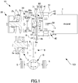
- Fig. 1 is a schematic diagram of the vehicle 100. As illustrated in Fig. 1 , the vehicle 100 includes an engine 1, and the power transmission device 10 provided in a power transmission path that connects the engine 1 and drive wheels 5.
- the power transmission device 10 is a transmission, and includes a variator 20, a forward/reverse switching mechanism 30, and a rotating electric machine 40.
- the rotating electric machine 40 is provided between the variator 20 and the engine 1 in the power transmission path.
- the rotating electric machine 40 includes a housing 41, a cover 42 as a fixed member provided on an opening on the engine 1 side of the housing 41, a stator 43 provided on an inner circumference of the housing 41, a rotating shaft 44, a rotor 80 provided on an outer circumference of the rotating shaft 44, and a clutch 48 that connects and disconnects the rotor 80 and an input shaft 11.
- the rotor 80 includes a rotor frame 81, and a core 82 provided on an outer circumference of the rotor frame 81.
- the rotating electric machine 40 is fixed to the power transmission device 10 by having the cover 42 fastened to a case 12 of the power transmission device 10 with a bolt (not illustrated).
- the input shaft 11 is rotatably supported to the cover 42 via a bearing 50, and receives output rotation of the engine 1.
- the rotating shaft 44 is rotatably supported to the housing 41 via a bearing 51.
- the clutch 48 is a normally open hydraulic clutch.
- the clutch 48 is controlled in engaging and disengaging by hydraulic pressure regulated by a hydraulic control valve unit (not illustrated).
- the clutch 48 is a wet multiple-plate clutch, however other clutches may be used.
- the rotating electric machine 40 may operate as an electric motor that drives by rotation in response to receiving electric power from a battery (not illustrated). Moreover, the rotating electric machine 40 functions as a generator in a case in which the rotor 80 receives rotating energy from the drive wheels 5, and can charge the battery.
- the variator 20 has a primary pulley 2 and a secondary pulley 3 disposed so that their V-grooves are aligned, and a belt 4 provided across the V-grooves of the pulleys 2, 3.
- the engine 1 is arranged coaxially to the primary pulley 2, and the rotating electric machine 40 and the forward/reverse switching mechanism 30 are provided between the engine 1 and the primary pulley 2, in the order from the engine 1, the rotating electric machine 40, the forward/reverse switching mechanism 30, and the primary pulley 2.
- the forward/reverse switching mechanism 30 has a double pinion planetary gear set 30a as its main component, whose sun gear is coupled to the rotating shaft 44 of the rotating electric machine 40, and whose carrier is coupled to the primary pulley 2 of the variator 20.
- the forward/reverse switching mechanism 30 further includes a forward clutch 30b that directly links the sun gear and the carrier of the double pinion planetary gear set 30a, and a reverse brake 30c that fixes a ring gear.
- a forward clutch 30b that directly links the sun gear and the carrier of the double pinion planetary gear set 30a
- a reverse brake 30c that fixes a ring gear.
- the forward clutch 30b engages by clutch pressure being supplied from the hydraulic control valve unit in a case in which a forward running mode is selected as a running mode of the vehicle 100.
- the reverse brake 30c engages by brake pressure being supplied from the hydraulic control valve unit in a case in which a reverse running mode is selected as the running mode of the vehicle 100.
- Rotation of the primary pulley 2 is transmitted to the secondary pulley 3 via the belt 4, and the rotation of the secondary pulley 3 is transmitted to the drive wheels 5 through the output shaft 8, a gear set 9 and a differential gear device 15.
- one of conical plates that form the V-grooves of the primary pulley 2 and the secondary pulley 3 is fixed conical plates 2a, 3a, and the other is to be movable conical plates 2b, 3b that can be displaced in the axial direction.
- a target speed ratio is achieved by varying a width of the V-grooves of the primary pulley 2 and the secondary pulley 3 by a pressure difference between the primary pulley pressure and the secondary pulley pressure caused in accordance with the target speed ratio, and continuously changing a diameter of a winding arc of the belt 4 with respect to the pulleys 2, 3.
- a pipe 53 as a refrigerant liquid feeding member that extends in an arc form along the circumferential direction of the rotating electric machine 40
- an intermediate cover 31 that covers the forward/reverse switching mechanism 30 on the rotating electric machine 40 side and that faces the rotating electric machine 40 in the axial direction via the pipe 53.
- the intermediate cover 31 is equivalent to an opposing member, and opposes the housing 41 of the rotating electric machine 40.
- the pipe 53 is connected to an oil passage provided inside the intermediate cover 31, and is configured to eject oil supplied via the intermediate cover 31 towards the stator 43 of the rotating electric machine 40 from a plurality of holes 53a formed on the rotating electric machine 40 side.
- An oil reservoir 41d forming an oil pool is provided at the lower part of the housing 41, and the lower part side of the housing 41 is cooled by the oil flowing down from an upper part of the housing 41.
- the oil reservoir 41d is for example formed below the clutch 48, and in the oil reservoir 41d, oil is pooled up to a position higher than a lower edge of the core 82 for example.
- the oil is equivalent to the refrigerant liquid, and the oil reservoir 41d is equivalent to a refrigerant liquid reservoir.
- the intermediate cover 31 has a sprocket 55 rotatably supported via a bushing 54.
- the sprocket 55 is connected to the rotating shaft 44 of the rotating electric machine 40 via a connecting member 56, and the sprocket 55 is further coupled to a sprocket 6b provided on an input shaft 6a of an oil pump 6 with a chain 57. This causes the oil pump 6 to be driven when the rotating electric machine 40 rotates, thus feeding oil to the hydraulic control valve unit.
- the bushing 54 and the sprocket 55 are provided at locations that overlap the pipe 53 in a radial direction.
- overlap in a radial direction means to be disposed so that at least one part thereof overlaps when viewed from the radial direction.
- the chain 57 is disposed between one end and the other end of the arc-shaped pipe 53, namely, to be passed through a cut-out of the pipe 53.
- a protrusion 41e and a protrusion 31a are provided between the sprocket 55 and the pipe 53.
- the protrusion 41e is provided on the housing 41, and protrudes in the axial direction from the housing 41.
- the protrusion 31a is provided on the intermediate cover 31, and protrudes in the axial direction from the intermediate cover 31.
- the protrusion 41e and the protrusion 31a overlap in the radial direction.
- the protrusion 41e and the protrusion 31a abut each other in the radial direction. Peripheral parts of the housing 41 and the intermediate cover 31 are further described later.
- the vehicle 100 is configured as above, and has, as driving modes, an EV mode that runs by driving force from just the rotating electric machine 40 by driving the rotating electric machine 40 with electric power supplied from the battery, an engine running mode that runs by driving force by just the engine 1, and an HEV mode that runs by the driving force of the engine 1 and the driving force of the rotating electric machine 40.
- the vehicle 100 runs by driving just the rotating electric machine 40 by the electric power from the battery, in a state disengaging the clutch 48 and engaging one of either the forward clutch 30b or the reverse brake 30c.
- the vehicle 100 runs by driving just the engine 1 in a state engaging the clutch 48 and one of either the forward clutch 30b or the reverse brake 30c.
- the vehicle 100 runs by driving the engine 1 and the rotating electric machine 40 in a state engaging the clutch 48 and one of either the forward clutch 30b or the reverse brake 30c.
- Fig. 2 is a cross-sectional view of the rotating electric machine 40.
- the housing 41 has a cylindrical portion 41a provided on an outer circumference side, and a cylindrical portion 41b provided on an inner circumference side and extending internally into the housing 41.
- the inner circumference of the cylindrical portion 41a has the stator 43 fixed thereon.
- the cylindrical portion 41b rotatably supports the rotating shaft 44 via the bearing 51.
- the stator 43 is configured by having a stator core 431, an insulator 432, and a stator coil 433.
- the stator core 431 is configured by stacking a plurality of thin electromagnetic steel plates.
- the insulator 432 is for example made of resin, and is provided on the stator core 431 to insulate the stator core 431 and the stator coil 433.
- the stator coil 433 is wound on a coil winding portion 432a of the insulator 432.
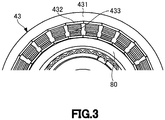
- Fig. 3 is a view illustrating an essential part of the stator 43.
- Fig. 3 illustrates the essential part of the stator 43 viewed along the axial direction from the pipe 53 side.
- the insulator 432 is provided in a plural number along a circumferential direction of the rotating electric machine 40.
- the stator core 431 has a plurality of projections extending internally in the radial direction from a ring-shaped part, and the insulators 432 are mounted on the projections.
- the stator coil 433 is wound on the insulators 432 in the state mounted on the stator core 431.
- an opening 41c is formed on a plane of the housing 41 that opposes the pipe 53. Accordingly, as shown by the arrow, oil ejected from the hole 53a of the pipe 53 is sprayed directly to the stator coil 433 through the opening 41c.
- the hole 53a is equivalent to the refrigerant liquid feeding port.
- the cover 42 is fixed to the case 12 of the power transmission device 10 at an outer circumference side. Moreover, the cover 42 has a cylindrical portion 42a provided in the inner circumference side and extending towards the housing 41 side. The cylindrical portion 42a rotatably supports the input shaft 11 via the bearing 50.
- a sealing member 59 for preventing leakage of oil to the outside.
- a needle bearing 60 that receives load in the axial direction and a needle bearing 61 that receives load in the radial direction.
- a clutch hub 62 is fixed on an end portion of the input shaft 11 on the forward/reverse switching mechanism 30 side, by welding.
- the clutch hub 62 has a cylindrical portion 62a provided on the outer circumference side and which extends towards the engine 1.
- a plurality of drive plates 48a of the clutch 48 is splined to the outer circumference of the cylindrical portion 62a, in a manner slidable in the axial direction.
- a rotor frame 81 is fixed on the outer circumference of the rotating shaft 44, by welding.
- the rotor frame 81 has a cylindrical portion 81a provided on the outer circumference side.
- a core 82 is fixed on the outer circumference of the cylindrical portion 81a.
- Driven plates 48b of the clutch 48 are splined to an inner circumference of the cylindrical portion 81a, in a manner slidable in the axial direction.
- a retainer plate 63 is placed between the driven plates 48b disposed at an end portion opposite of a piston arm 64, and a ring 65 fixed to a groove on the inner circumference of the cylindrical portion 81a.
- the retainer plate 63 has a thickness in the axial direction thicker than the driven plates 48b, and prevents the drive plates 48a and the driven plates 48b from leaning.
- Fig. 4 is a view illustrating the housing 41 together with the pipe 53.
- Fig. 5 is a view illustrating the intermediate cover 31 together with the pipe 53 and the chain 57.
- Fig. 4 is a view looking at the housing 41 from the intermediate cover 31 side
- Fig. 5 is a view looking at the intermediate cover 31 from the housing 41 side.
- the opening 41c is provided at the upper part of the housing 41.
- the opening 41c is shaped long in the circumferential direction, and a plurality thereof (three in this embodiment) is provided along the circumferential direction.
- the shapes and numbers of the opening 41c is not limited to this, and may be of different shapes and numbers.
- the opening 41c introduces oil ejected from the holes 53a of the pipe 53 to the inside of the housing 41.
- the holes 53a are at the back side of the pipe 53, and are open as illustrated in Fig. 5 .
- the holes 53a may be configured by a nozzle.
- the oil introduced from the opening 41c illustrated in Fig. 4 is fed to the stator 43 housed in the housing 41.
- the opening 41c is equivalent to the introduction port.
- the pipe 53 is provided outside the housing 41, and has a cut-out between one end and the other end thereof.
- the pipe 53 is an arc-shaped pipe of an arc form.
- the arc form is to have a curved form with an upper convex shape, and for example may be of an ellipse arc form.
- a communication port 41g is provided at the lower part of the housing 41.
- the communication port 41g links with the case 12 that houses the housing 41, and communicates the inside of the case of the power transmission device 10 that houses the intermediate cover 31 and the pipe 53 with the oil reservoir 41d.
- the communication port 41g discharges oil from the oil reservoir 41d, and a liquid surface height of the oil reservoir 41d is defined by a lower edge of the communication port 41g.
- the liquid surface L illustrated by the broken line is a liquid surface of the oil reservoir 41d defined in accordance with the lower edge of the communication port 41g, and illustrates the liquid surface on a front surface of the communication port 41g of the stator coil 433.
- the lower edge of the communication port 41g is provided overlapping the stator coil 433 in the axial direction.
- this case prevents intrusion of the oil into an air gap in a motor part of the rotating electric machine 40 (air gap formed by a gap between the stator 43 and the rotor 80).
- the liquid surface height of the oil reservoir 41d is located on the outer circumference side than the lower edge of the outermost circumference of the stator coil 433 immersed in the oil of the oil reservoir 41d, the oil intrudes into the air gap from the oil reservoir 41d, thus causing a large rotational resistance against the rotor 80, the case of the present invention prevents the occurrence of such circumstance.
- the communication port 41g is equivalent to a discharge port.
- the chain 57 extends from the inner circumference side of the pipe 53 to the outer circumference side of the pipe 53 via the cut-out of the pipe 53.
- the inner circumference side of the pipe 53 is provided with a sprocket 55 that drives the chain 57.
- the sprocket 55 is equivalent to a chain sprocket.
- the housing 41 has depressions 41f that oppose the chain 57.
- the chain 57 and the sprocket 55 are disposed close to the housing 41 by the degree to which interference between the housing 41 and the chain 57 is avoided by the depression 41f.
- the protrusion 41e and the protrusion 31a are both provided in a manner surrounding the sprocket 55.
- the protrusion 41e and the protrusion 31a are both formed in an arc form as with the pipe 53, and have cut-outs between one end and the other end thereof. Therefore, the chain 57 does not interfere with the protrusion 41e and the protrusion 31a.
- the protrusion 41e and the protrusion 31a both function as a cover that prevents the oil from flowing down and pouring onto the sprocket 55 from the pipe 53 and the housing 41 upon ejection from the pipe 53.
- the protrusion 41e is equivalent to a housing protrusion
- the protrusion 31a is equivalent to an opposing member protrusion.
- the protrusion 41e and the protrusion 31a both configure a partition that surrounds the sprocket 55, between the pipe 53 and the sprocket 55.
- the power transmission device 10 has the rotating electric machine 40, the housing 41 that houses the stator 43 of the rotating electric machine 40, and the pipe 53 as a refrigerant liquid feeding member that has the holes 53a.
- the opening 41c that introduces oil ejected from the holes 53a.
- the oil reservoir 41d that forms an oil pool.
- the pipe 53 is configured by an arc-shaped pipe.
- the power transmission device 10 has the chain 57 that extends from the inner circumference side of the pipe 53 to the outer circumference side of the pipe 53 via the cut-out of the pipe 53, and the sprocket 55 provided on the inner circumference side of the pipe 53 and which drives the chain 57.
- the lower part of the housing 41 is provided with the communication port 41g that discharges oil.
- the lower edge of the communication port 41g overlaps the stator coil 433 in the axial direction.
- the liquid surface height of the oil reservoir 41d is located on the inner circumference side than the lower edge in the outermost circumference of the stator coil 433 immersed in the oil of the oil reservoir 41d. Therefore, it becomes possible to achieve both the securing of cooling property of the stator coil 433 and the prevention of oil intrusion into the air gap in the motor part of the rotating electric machine 40.
- the pipe 53 does not need to be provided for the entire circumference. Therefore, it is possible to enlarge the cut-out, thus it is possible to extend the chain 57 from the inner circumference side of the pipe 53 to the outer circumference side via the cut-out. Therefore, it is possible to provide the sprocket 55 so as to overlap the pipe 53 in the radial direction, which accordingly can reduce the size in the axial direction.
- the power transmission device 10 has the protrusion 41e and the protrusion 31a as partitions that surround the sprocket 55, between the pipe 53 and the sprocket 55.
- the partition is configured to include the protrusion 41e that protrudes from the housing 41 in the axial direction.
- the number of components may be reduced by configuring the partition by using the housing 41 existing in the power transmission device 10.
- the power transmission device 10 has the intermediate cover 31 that opposes the housing 41, and the partition is configured to include the protrusion 31a that protrudes from the intermediate cover 31 in the axial direction.
- the number of components may be reduced by configuring the partition by using the intermediate cover 31 existing in the power transmission device 10.
- the power transmission device 10 has the intermediate cover 31 that opposes the housing 41, and the partition is configured to include the protrusion 41e and the protrusion 31a.
- the protrusion 41e and the protrusion 31a overlap in the radial direction.
- the number of components may be reduced by configuring the partition by using the housing 41 and the intermediate cover 31 which exist in the power transmission device 10.
- the two protrusions, the protrusion 41e and the protrusion 31a are used to overlap these two in the radial direction; hence it is possible to further reduce the amount of oil that may flow to the sprocket 55.
- the housing 41 has the depression 41f that opposes the chain 57.
- the device is described as the power transmission device 10.
- the device may be a rotating electric machine installed device (a device installing a rotating electric machine) or the like, and the power transmission device 10 may be recognized as the rotating electric machine installed device.
- the power transmission device 10 is described as a transmission.
- the power transmission device 10 may be a reducer, a transmission with a motor (also a rotating electric machine installed device), a reducer with a motor (also a rotating electric machine installed device), or the like.
Landscapes
- Engineering & Computer Science (AREA)
- Power Engineering (AREA)
- Motor Or Generator Cooling System (AREA)
- Hybrid Electric Vehicles (AREA)
Abstract
Description
- The present invention relates to a device.
-
JP2015-211543A - In a case in which oil is fed across the entire circumference of the rotating electric machine, the number of nozzles (refrigerant liquid feeding port) becomes large. If the number of nozzles is large, spraying force of each one of the nozzles tends to decrease.
- The present invention is accomplished in view of such problem, and an object thereof is to reduce the number of refrigerant liquid feeding ports in cooling a rotating electric machine.
- A device of an aspect of the present invention includes a rotating electric machine, a housing configured to house a stator of the rotating electric machine, and a refrigerant liquid feeding member provided outside the housing and which has a refrigerant liquid feeding port. The housing is provided with an introduction port in an upper part thereof, configured to introduce refrigerant liquid ejected from the refrigerant liquid feeding port, and the housing is provided with a refrigerant liquid reservoir at a lower part thereof, configured to form a refrigerant liquid pool.
- According to the above aspect, at least the lower part side of the housing can be cooled by the refrigerant liquid flowing down from the upper part of the housing. Therefore, it is possible to omit a refrigerant liquid feeding port on the lower part side of the housing, thus it is possible to reduce the number of the refrigerant liquid feeding ports. Therefore, according to the above aspect, it is possible to reduce the number of the refrigerant liquid feeding ports in providing at least one or more of the refrigerant liquid feeding ports. As a result, it is possible to reduce the number of the refrigerant liquid feeding ports as much as possible, for example to the least necessary.
-
-
Fig. 1 is a schematic diagram of a hybrid vehicle including a device according to an embodiment of the present invention. -
Fig. 2 is a cross-sectional view of a rotating electric machine. -
Fig. 3 is a view illustrating an essential part of a stator. -
Fig. 4 is a view illustrating a housing together with a pipe. -
Fig. 5 is a view illustrating an intermediate cover together with a pipe and a chain. - An embodiment of the present invention will be described below with reference to accompanied drawings.
- Below describes a hybrid vehicle (Hereinafter, simply called "vehicle") 100 including a
power transmission device 10 as a device according to the embodiment of the present invention, with reference to the accompanied drawings. -
Fig. 1 is a schematic diagram of thevehicle 100. As illustrated inFig. 1 , thevehicle 100 includes an engine 1, and thepower transmission device 10 provided in a power transmission path that connects the engine 1 anddrive wheels 5. - In the present embodiment, the
power transmission device 10 is a transmission, and includes avariator 20, a forward/reverse switching mechanism 30, and a rotatingelectric machine 40. - The rotating
electric machine 40 is provided between thevariator 20 and the engine 1 in the power transmission path. - The rotating
electric machine 40 includes ahousing 41, acover 42 as a fixed member provided on an opening on the engine 1 side of thehousing 41, astator 43 provided on an inner circumference of thehousing 41, arotating shaft 44, arotor 80 provided on an outer circumference of the rotatingshaft 44, and aclutch 48 that connects and disconnects therotor 80 and aninput shaft 11. Therotor 80 includes arotor frame 81, and acore 82 provided on an outer circumference of therotor frame 81. - The rotating
electric machine 40 is fixed to thepower transmission device 10 by having thecover 42 fastened to acase 12 of thepower transmission device 10 with a bolt (not illustrated). - The
input shaft 11 is rotatably supported to thecover 42 via abearing 50, and receives output rotation of the engine 1. Moreover, the rotatingshaft 44 is rotatably supported to thehousing 41 via abearing 51. - The
clutch 48 is a normally open hydraulic clutch. Theclutch 48 is controlled in engaging and disengaging by hydraulic pressure regulated by a hydraulic control valve unit (not illustrated). Theclutch 48 is a wet multiple-plate clutch, however other clutches may be used. - When the
clutch 48 is engaged, theinput shaft 11 and therotor 80 are directly linked. Namely, theinput shaft 11 and the rotatingshaft 44 are directly linked and rotates at the same velocity. - The rotating
electric machine 40 may operate as an electric motor that drives by rotation in response to receiving electric power from a battery (not illustrated). Moreover, the rotatingelectric machine 40 functions as a generator in a case in which therotor 80 receives rotating energy from thedrive wheels 5, and can charge the battery. - The
variator 20 has aprimary pulley 2 and asecondary pulley 3 disposed so that their V-grooves are aligned, and a belt 4 provided across the V-grooves of thepulleys - The engine 1 is arranged coaxially to the
primary pulley 2, and the rotatingelectric machine 40 and the forward/reverse switching mechanism 30 are provided between the engine 1 and theprimary pulley 2, in the order from the engine 1, the rotatingelectric machine 40, the forward/reverse switching mechanism 30, and theprimary pulley 2. - The forward/
reverse switching mechanism 30 has a double pinion planetary gear set 30a as its main component, whose sun gear is coupled to the rotatingshaft 44 of the rotatingelectric machine 40, and whose carrier is coupled to theprimary pulley 2 of thevariator 20. The forward/reverse switching mechanism 30 further includes aforward clutch 30b that directly links the sun gear and the carrier of the double pinion planetary gear set 30a, and areverse brake 30c that fixes a ring gear. At a time of engaging theforward clutch 30b, inputted rotation from the rotatingshaft 44 is transmitted to theprimary pulley 2 in a rotating direction as it is, and at a time of engaging thereverse brake 30c, the inputted rotation from the rotatingshaft 44 is reversed and is transmitted to theprimary pulley 2. - The
forward clutch 30b engages by clutch pressure being supplied from the hydraulic control valve unit in a case in which a forward running mode is selected as a running mode of thevehicle 100. Thereverse brake 30c engages by brake pressure being supplied from the hydraulic control valve unit in a case in which a reverse running mode is selected as the running mode of thevehicle 100. - Rotation of the
primary pulley 2 is transmitted to thesecondary pulley 3 via the belt 4, and the rotation of thesecondary pulley 3 is transmitted to thedrive wheels 5 through theoutput shaft 8, agear set 9 and adifferential gear device 15. - To enable variation in speed ratio between the
primary pulley 2 and thesecondary pulley 3 during the above power transmission, one of conical plates that form the V-grooves of theprimary pulley 2 and thesecondary pulley 3 is fixedconical plates conical plates - These movable
conical plates conical plates primary pulley 2 and thesecondary pulley 3. - In the shift, a target speed ratio is achieved by varying a width of the V-grooves of the
primary pulley 2 and thesecondary pulley 3 by a pressure difference between the primary pulley pressure and the secondary pulley pressure caused in accordance with the target speed ratio, and continuously changing a diameter of a winding arc of the belt 4 with respect to thepulleys - Between the rotating
electric machine 40 and the forward/reverse switching mechanism 30 are provided apipe 53 as a refrigerant liquid feeding member that extends in an arc form along the circumferential direction of the rotatingelectric machine 40, and anintermediate cover 31 that covers the forward/reverse switching mechanism 30 on the rotatingelectric machine 40 side and that faces the rotatingelectric machine 40 in the axial direction via thepipe 53. Theintermediate cover 31 is equivalent to an opposing member, and opposes thehousing 41 of the rotatingelectric machine 40. - The
pipe 53 is connected to an oil passage provided inside theintermediate cover 31, and is configured to eject oil supplied via theintermediate cover 31 towards thestator 43 of the rotatingelectric machine 40 from a plurality ofholes 53a formed on the rotatingelectric machine 40 side. - An
oil reservoir 41d forming an oil pool is provided at the lower part of thehousing 41, and the lower part side of thehousing 41 is cooled by the oil flowing down from an upper part of thehousing 41. Theoil reservoir 41d is for example formed below theclutch 48, and in theoil reservoir 41d, oil is pooled up to a position higher than a lower edge of thecore 82 for example. The oil is equivalent to the refrigerant liquid, and theoil reservoir 41d is equivalent to a refrigerant liquid reservoir. - The
intermediate cover 31 has asprocket 55 rotatably supported via abushing 54. Thesprocket 55 is connected to the rotatingshaft 44 of the rotatingelectric machine 40 via a connectingmember 56, and thesprocket 55 is further coupled to asprocket 6b provided on aninput shaft 6a of anoil pump 6 with achain 57. This causes theoil pump 6 to be driven when the rotatingelectric machine 40 rotates, thus feeding oil to the hydraulic control valve unit. - The
bushing 54 and thesprocket 55 are provided at locations that overlap thepipe 53 in a radial direction. To "overlap in a radial direction" means to be disposed so that at least one part thereof overlaps when viewed from the radial direction. Moreover, as illustrated inFigs. 4 and5 described later, thechain 57 is disposed between one end and the other end of the arc-shaped pipe 53, namely, to be passed through a cut-out of thepipe 53. Thus, it is possible to hold down the size of thepower transmission device 10 in the axial direction. - A
protrusion 41e and aprotrusion 31a are provided between thesprocket 55 and thepipe 53. Theprotrusion 41e is provided on thehousing 41, and protrudes in the axial direction from thehousing 41. Theprotrusion 31a is provided on theintermediate cover 31, and protrudes in the axial direction from theintermediate cover 31. Theprotrusion 41e and theprotrusion 31a overlap in the radial direction. Theprotrusion 41e and theprotrusion 31a abut each other in the radial direction. Peripheral parts of thehousing 41 and theintermediate cover 31 are further described later. - The
vehicle 100 is configured as above, and has, as driving modes, an EV mode that runs by driving force from just the rotatingelectric machine 40 by driving the rotatingelectric machine 40 with electric power supplied from the battery, an engine running mode that runs by driving force by just the engine 1, and an HEV mode that runs by the driving force of the engine 1 and the driving force of the rotatingelectric machine 40. - In the EV mode, the
vehicle 100 runs by driving just the rotatingelectric machine 40 by the electric power from the battery, in a state disengaging the clutch 48 and engaging one of either the forward clutch 30b or thereverse brake 30c. - In the engine running mode, the
vehicle 100 runs by driving just the engine 1 in a state engaging the clutch 48 and one of either the forward clutch 30b or thereverse brake 30c. - In the HEV mode, the
vehicle 100 runs by driving the engine 1 and the rotatingelectric machine 40 in a state engaging the clutch 48 and one of either the forward clutch 30b or thereverse brake 30c. - Next describes a configuration of the rotating
electric machine 40 in details, with reference toFig. 2. Fig. 2 is a cross-sectional view of the rotatingelectric machine 40. - As illustrated in
Fig. 2 , thehousing 41 has acylindrical portion 41a provided on an outer circumference side, and acylindrical portion 41b provided on an inner circumference side and extending internally into thehousing 41. The inner circumference of thecylindrical portion 41a has thestator 43 fixed thereon. Thecylindrical portion 41b rotatably supports therotating shaft 44 via thebearing 51. - The
stator 43 is configured by having astator core 431, aninsulator 432, and astator coil 433. Thestator core 431 is configured by stacking a plurality of thin electromagnetic steel plates. Theinsulator 432 is for example made of resin, and is provided on thestator core 431 to insulate thestator core 431 and thestator coil 433. Thestator coil 433 is wound on acoil winding portion 432a of theinsulator 432. -
Fig. 3 is a view illustrating an essential part of thestator 43.Fig. 3 illustrates the essential part of thestator 43 viewed along the axial direction from thepipe 53 side. Theinsulator 432 is provided in a plural number along a circumferential direction of the rotatingelectric machine 40. Thestator core 431 has a plurality of projections extending internally in the radial direction from a ring-shaped part, and theinsulators 432 are mounted on the projections. Thestator coil 433 is wound on theinsulators 432 in the state mounted on thestator core 431. - Returning back to
Fig. 2 , anopening 41c is formed on a plane of thehousing 41 that opposes thepipe 53. Accordingly, as shown by the arrow, oil ejected from thehole 53a of thepipe 53 is sprayed directly to thestator coil 433 through theopening 41c. - As a result, the
stator coil 433 that generates heat is efficiently cooled. Therefore, it is possible to cool thestator 43 efficiently, thus it is possible to cool the rotatingelectric machine 40 efficiently. Thehole 53a is equivalent to the refrigerant liquid feeding port. - The
cover 42 is fixed to thecase 12 of thepower transmission device 10 at an outer circumference side. Moreover, thecover 42 has acylindrical portion 42a provided in the inner circumference side and extending towards thehousing 41 side. Thecylindrical portion 42a rotatably supports theinput shaft 11 via thebearing 50. - Between the
cylindrical portion 42a and theinput shaft 11 is provided a sealingmember 59 for preventing leakage of oil to the outside. - Between the
input shaft 11 and therotating shaft 44 are provided aneedle bearing 60 that receives load in the axial direction and aneedle bearing 61 that receives load in the radial direction. - A
clutch hub 62 is fixed on an end portion of theinput shaft 11 on the forward/reverse switching mechanism 30 side, by welding. Theclutch hub 62 has acylindrical portion 62a provided on the outer circumference side and which extends towards the engine 1. A plurality ofdrive plates 48a of the clutch 48 is splined to the outer circumference of thecylindrical portion 62a, in a manner slidable in the axial direction. - A
rotor frame 81 is fixed on the outer circumference of therotating shaft 44, by welding. Therotor frame 81 has acylindrical portion 81a provided on the outer circumference side. Acore 82 is fixed on the outer circumference of thecylindrical portion 81a. - Driven
plates 48b of the clutch 48 are splined to an inner circumference of thecylindrical portion 81a, in a manner slidable in the axial direction. Aretainer plate 63 is placed between the drivenplates 48b disposed at an end portion opposite of apiston arm 64, and aring 65 fixed to a groove on the inner circumference of thecylindrical portion 81a. Theretainer plate 63 has a thickness in the axial direction thicker than the drivenplates 48b, and prevents thedrive plates 48a and the drivenplates 48b from leaning. - When engaging pressure is supplied from the hydraulic control valve unit to a
piston oil chamber 66, apiston 67 moves towards the engine 1 side upon compressing areturn spring 68. The clutch 48 becomes in an engaged state by pressing force transmitted from thepiston 67 via aneedle bearing 69 and thepiston arm 64. Theneedle bearing 69 prevents thepiston 67 from corotating together with the rotation of thepiston arm 64. - Next describes the peripheral portions of the
housing 41 and theintermediate cover 31 that opposes thehousing 41, with reference toFigs. 4 and5 . -
Fig. 4 is a view illustrating thehousing 41 together with thepipe 53.Fig. 5 is a view illustrating theintermediate cover 31 together with thepipe 53 and thechain 57.Fig. 4 is a view looking at thehousing 41 from theintermediate cover 31 side, andFig. 5 is a view looking at theintermediate cover 31 from thehousing 41 side. - As illustrated in
Fig. 4 , theopening 41c is provided at the upper part of thehousing 41. Theopening 41c is shaped long in the circumferential direction, and a plurality thereof (three in this embodiment) is provided along the circumferential direction. The shapes and numbers of theopening 41c is not limited to this, and may be of different shapes and numbers. - The
opening 41c introduces oil ejected from theholes 53a of thepipe 53 to the inside of thehousing 41. InFig. 4 , theholes 53a are at the back side of thepipe 53, and are open as illustrated inFig. 5 . Theholes 53a may be configured by a nozzle. The oil introduced from theopening 41c illustrated inFig. 4 is fed to thestator 43 housed in thehousing 41. Theopening 41c is equivalent to the introduction port. - The
pipe 53 is provided outside thehousing 41, and has a cut-out between one end and the other end thereof. Thepipe 53 is an arc-shaped pipe of an arc form. The arc form is to have a curved form with an upper convex shape, and for example may be of an ellipse arc form. - A
communication port 41g is provided at the lower part of thehousing 41. Thecommunication port 41g links with thecase 12 that houses thehousing 41, and communicates the inside of the case of thepower transmission device 10 that houses theintermediate cover 31 and thepipe 53 with theoil reservoir 41d. - The
communication port 41g discharges oil from theoil reservoir 41d, and a liquid surface height of theoil reservoir 41d is defined by a lower edge of thecommunication port 41g. The liquid surface L illustrated by the broken line is a liquid surface of theoil reservoir 41d defined in accordance with the lower edge of thecommunication port 41g, and illustrates the liquid surface on a front surface of thecommunication port 41g of thestator coil 433. - As obvious from the liquid surface L, the lower edge of the
communication port 41g is provided overlapping thestator coil 433 in the axial direction. This makes the liquid surface height of theoil reservoir 41d be located on the inner circumference side than a lower edge of an outermost circumference of thestator coil 433 immersed in the oil of theoil reservoir 41d. This results to securing contact between thestator coil 433 and the oil in theoil reservoir 41d, thus enhancing the cooling effect. - Furthermore, this case prevents intrusion of the oil into an air gap in a motor part of the rotating electric machine 40 (air gap formed by a gap between the
stator 43 and the rotor 80). As a result, in a case in which the liquid surface height of theoil reservoir 41d is located on the outer circumference side than the lower edge of the outermost circumference of thestator coil 433 immersed in the oil of theoil reservoir 41d, the oil intrudes into the air gap from theoil reservoir 41d, thus causing a large rotational resistance against therotor 80, the case of the present invention prevents the occurrence of such circumstance. Thecommunication port 41g is equivalent to a discharge port. - As illustrated in
Fig. 5 , thechain 57 extends from the inner circumference side of thepipe 53 to the outer circumference side of thepipe 53 via the cut-out of thepipe 53. The inner circumference side of thepipe 53 is provided with asprocket 55 that drives thechain 57. Thesprocket 55 is equivalent to a chain sprocket. - As illustrated in
Fig. 4 , thehousing 41 hasdepressions 41f that oppose thechain 57. Thechain 57 and thesprocket 55 are disposed close to thehousing 41 by the degree to which interference between thehousing 41 and thechain 57 is avoided by thedepression 41f. - As illustrated in
Figs. 4 and5 , theprotrusion 41e and theprotrusion 31a are both provided in a manner surrounding thesprocket 55. Theprotrusion 41e and theprotrusion 31a are both formed in an arc form as with thepipe 53, and have cut-outs between one end and the other end thereof. Therefore, thechain 57 does not interfere with theprotrusion 41e and theprotrusion 31a. - The
protrusion 41e and theprotrusion 31a both function as a cover that prevents the oil from flowing down and pouring onto thesprocket 55 from thepipe 53 and thehousing 41 upon ejection from thepipe 53. Theprotrusion 41e is equivalent to a housing protrusion, and theprotrusion 31a is equivalent to an opposing member protrusion. Theprotrusion 41e and theprotrusion 31a both configure a partition that surrounds thesprocket 55, between thepipe 53 and thesprocket 55. - Next describes main operations and effects of the present embodiment.
- The
power transmission device 10 has the rotatingelectric machine 40, thehousing 41 that houses thestator 43 of the rotatingelectric machine 40, and thepipe 53 as a refrigerant liquid feeding member that has theholes 53a. In the upper part of thehousing 41 is provided theopening 41c that introduces oil ejected from theholes 53a. In the lower part of thehousing 41 is provided theoil reservoir 41d that forms an oil pool. - According to such a configuration, it is at least possible to perform cooling by the oil flowing down from the upper part of the
housing 41 at the lower part side of thehousing 41. It is hence possible to omit theholes 53a on the lower part side of thehousing 41, thus it is possible to reduce the number of theholes 53a. Therefore, according to such a configuration, it is possible to reduce the number ofholes 53a in providing at least one or more of theholes 53a. As a result, it becomes possible to reduce the number of theholes 53a as much as possible, for example to the least necessary. - In the present embodiment, the
pipe 53 is configured by an arc-shaped pipe. Thepower transmission device 10 has thechain 57 that extends from the inner circumference side of thepipe 53 to the outer circumference side of thepipe 53 via the cut-out of thepipe 53, and thesprocket 55 provided on the inner circumference side of thepipe 53 and which drives thechain 57. - In the present embodiment, the lower part of the
housing 41 is provided with thecommunication port 41g that discharges oil. The lower edge of thecommunication port 41g overlaps thestator coil 433 in the axial direction. - According to such a configuration, the liquid surface height of the
oil reservoir 41d is located on the inner circumference side than the lower edge in the outermost circumference of thestator coil 433 immersed in the oil of theoil reservoir 41d. Therefore, it becomes possible to achieve both the securing of cooling property of thestator coil 433 and the prevention of oil intrusion into the air gap in the motor part of the rotatingelectric machine 40. - According to such a configuration, the
pipe 53 does not need to be provided for the entire circumference. Therefore, it is possible to enlarge the cut-out, thus it is possible to extend thechain 57 from the inner circumference side of thepipe 53 to the outer circumference side via the cut-out. Therefore, it is possible to provide thesprocket 55 so as to overlap thepipe 53 in the radial direction, which accordingly can reduce the size in the axial direction. - The
power transmission device 10 has theprotrusion 41e and theprotrusion 31a as partitions that surround thesprocket 55, between thepipe 53 and thesprocket 55. - According to such a configuration, it is possible to prevent an increase in agitation resistance of oil in the
sprocket 55 by the oil flowing down from thepipe 53 and/or thehousing 41 being poured onto thesprocket 55. - In the present embodiment, the partition is configured to include the
protrusion 41e that protrudes from thehousing 41 in the axial direction. - According to such a configuration, the number of components may be reduced by configuring the partition by using the
housing 41 existing in thepower transmission device 10. - In the present embodiment, the
power transmission device 10 has theintermediate cover 31 that opposes thehousing 41, and the partition is configured to include theprotrusion 31a that protrudes from theintermediate cover 31 in the axial direction. - According to such a configuration, the number of components may be reduced by configuring the partition by using the
intermediate cover 31 existing in thepower transmission device 10. - In the present embodiment, the
power transmission device 10 has theintermediate cover 31 that opposes thehousing 41, and the partition is configured to include theprotrusion 41e and theprotrusion 31a. Theprotrusion 41e and theprotrusion 31a overlap in the radial direction. - According to such a configuration, the number of components may be reduced by configuring the partition by using the
housing 41 and theintermediate cover 31 which exist in thepower transmission device 10. Moreover, the two protrusions, theprotrusion 41e and theprotrusion 31a are used to overlap these two in the radial direction; hence it is possible to further reduce the amount of oil that may flow to thesprocket 55. - In the present embodiment, the
housing 41 has thedepression 41f that opposes thechain 57. - According to such a configuration, it is possible to have the
chain 57 be closer to thehousing 41, thus it is possible to shorten thepower transmission device 10 in the axial direction. - In the above embodiment, the device is described as the
power transmission device 10. However, the device may be a rotating electric machine installed device (a device installing a rotating electric machine) or the like, and thepower transmission device 10 may be recognized as the rotating electric machine installed device. - Moreover, in the above embodiment, the
power transmission device 10 is described as a transmission. However, thepower transmission device 10 may be a reducer, a transmission with a motor (also a rotating electric machine installed device), a reducer with a motor (also a rotating electric machine installed device), or the like.
Claims (8)
- A device (10), comprising:a rotating electric machine (40);a housing (41) configured to house a stator (43) of the rotating electric machine (40); anda refrigerant liquid feeding member (53) provided outside the housing (41) and having a refrigerant liquid feeding port (53a),wherein the housing (41) has an introduction port (41e) formed in an upper part thereof, the introduction port configured to introduce refrigerant liquid ejected from the refrigerant liquid feeding port (53a), andwherein the housing (41) has a refrigerant liquid reservoir (41d) formed in a lower part thereof, the refrigerant liquid reservoir (41d) configured to form a refrigerant liquid pool.
- The device (10) according to claim 1, wherein
the housing (41) has a discharging port (41g) provided in the lower part of the housing (41), the discharging port (41g) configured to discharge the refrigerant liquid, and
the discharging port (41g) has a lower edge thereof overlapping a coil (433) of the stator (43) in an axial direction. - The device (10) according to claim 1 or 2, wherein
the refrigerant liquid feeding member (53) is configured by an arc-shaped pipe, and
the device (10) has a chain (57) extending from an inner circumference side of the arc-shaped pipe (53) to an outer circumference side of the arc-shaped pipe (53) via a cut-out of the arc-shaped pipe (53), and a chain sprocket (55) provided on the inner circumference side of the arc-shaped pipe (53) and configured to drive the chain (57). - The device (10) according to claim 3, wherein
the arc-shaped pipe (53) and the chain sprocket (55) has a partition (41e, 31a) therebetween, the partition (41e, 31a) configured to surround the chain sprocket (55). - The device (10) according to claim 4, wherein
the partition (41e, 31a) is configured to include a housing protrusion (41e) that protrudes from the housing (41) in an axial direction. - The device (10) according to claim 4, wherein
the device (10) includes an opposing member (31) that opposes the housing (41), and
the partition (41e, 31a) is configured to include an opposing member protrusion (31a) configured to protrude from the opposing member (31) in an axial direction. - The device (10) according to claim 4, wherein
the device (10) includes an opposing member (31) that opposes the housing (41),
the partition (41e, 31a) is configured to include a housing protrusion (41e) configured to protrude from the housing (41) in an axial direction and an opposing member protrusion (31a) configured to protrude from the opposing member (31) in an axial direction, and
the housing protrusion (41e) and the opposing member protrusion (31a) overlap in a radial direction. - The device (10) according to any one of claims 3 to 7, wherein the housing (41) has a depression (41f) that opposes the chain (57).
Applications Claiming Priority (1)
| Application Number | Priority Date | Filing Date | Title |
|---|---|---|---|
| JP2020021618A JP7397709B2 (en) | 2020-02-12 | 2020-02-12 | Device |
Publications (2)
| Publication Number | Publication Date |
|---|---|
| EP3866313A1 true EP3866313A1 (en) | 2021-08-18 |
| EP3866313B1 EP3866313B1 (en) | 2025-09-10 |
Family
ID=74556708
Family Applications (1)
| Application Number | Title | Priority Date | Filing Date |
|---|---|---|---|
| EP21155402.7A Active EP3866313B1 (en) | 2020-02-12 | 2021-02-05 | Device |
Country Status (4)
| Country | Link |
|---|---|
| US (1) | US11990824B2 (en) |
| EP (1) | EP3866313B1 (en) |
| JP (1) | JP7397709B2 (en) |
| CN (1) | CN113258724B (en) |
Cited By (1)
| Publication number | Priority date | Publication date | Assignee | Title |
|---|---|---|---|---|
| EP4106156A4 (en) * | 2020-02-12 | 2023-09-20 | Jatco Ltd. | CONTRAPTION |
Families Citing this family (1)
| Publication number | Priority date | Publication date | Assignee | Title |
|---|---|---|---|---|
| WO2023058350A1 (en) * | 2021-10-08 | 2023-04-13 | ジヤトコ株式会社 | Power transmission device |
Citations (4)
| Publication number | Priority date | Publication date | Assignee | Title |
|---|---|---|---|---|
| JP2003324901A (en) * | 2002-04-26 | 2003-11-14 | Nippon Soken Inc | Electric motor |
| JP2011036127A (en) * | 2010-11-01 | 2011-02-17 | Honda Motor Co Ltd | Engine generator cooling structure |
| JP2015211543A (en) | 2014-04-25 | 2015-11-24 | 本田技研工業株式会社 | Cooling structure of rotating electric machine |
| JP2018117479A (en) * | 2017-01-20 | 2018-07-26 | トヨタ自動車株式会社 | Rotating electric machine |
Family Cites Families (12)
| Publication number | Priority date | Publication date | Assignee | Title |
|---|---|---|---|---|
| JP3191319B2 (en) * | 1991-05-27 | 2001-07-23 | 株式会社デンソー | Vehicle generator |
| JP2005117790A (en) * | 2003-10-08 | 2005-04-28 | Toyota Motor Corp | Driving device and automobile equipped with the same |
| JP2012086826A (en) * | 2010-09-24 | 2012-05-10 | Aisin Aw Co Ltd | Vehicle drive device |
| KR101475369B1 (en) * | 2010-12-22 | 2014-12-23 | 가부시키가이샤 아이에이치아이 | Rotary machine |
| JP5716505B2 (en) | 2011-04-07 | 2015-05-13 | 株式会社デンソー | Rotating electric machine stator |
| JP2013005531A (en) * | 2011-06-14 | 2013-01-07 | Honda Motor Co Ltd | Outer rotor type rotary electric machine |
| JP6301725B2 (en) * | 2014-04-28 | 2018-03-28 | アイシン・エィ・ダブリュ株式会社 | Power transmission device |
| JP6620128B2 (en) * | 2017-08-02 | 2019-12-11 | 本田技研工業株式会社 | Cooling device for rotating electric machine |
| KR102463423B1 (en) * | 2017-10-13 | 2022-11-03 | 현대자동차주식회사 | Wound Rotor Motor of vehicle |
| JP2019126237A (en) * | 2018-01-19 | 2019-07-25 | トヨタ自動車株式会社 | Rotary electric machine |
| JP2019129608A (en) * | 2018-01-24 | 2019-08-01 | トヨタ自動車株式会社 | Vehicle drive |
| CN209860741U (en) * | 2019-04-15 | 2019-12-27 | 比亚迪股份有限公司 | Motor assembly and vehicle |
-
2020
- 2020-02-12 JP JP2020021618A patent/JP7397709B2/en active Active
-
2021
- 2021-02-05 EP EP21155402.7A patent/EP3866313B1/en active Active
- 2021-02-07 CN CN202110167920.2A patent/CN113258724B/en active Active
- 2021-02-09 US US17/171,123 patent/US11990824B2/en active Active
Patent Citations (4)
| Publication number | Priority date | Publication date | Assignee | Title |
|---|---|---|---|---|
| JP2003324901A (en) * | 2002-04-26 | 2003-11-14 | Nippon Soken Inc | Electric motor |
| JP2011036127A (en) * | 2010-11-01 | 2011-02-17 | Honda Motor Co Ltd | Engine generator cooling structure |
| JP2015211543A (en) | 2014-04-25 | 2015-11-24 | 本田技研工業株式会社 | Cooling structure of rotating electric machine |
| JP2018117479A (en) * | 2017-01-20 | 2018-07-26 | トヨタ自動車株式会社 | Rotating electric machine |
Cited By (1)
| Publication number | Priority date | Publication date | Assignee | Title |
|---|---|---|---|---|
| EP4106156A4 (en) * | 2020-02-12 | 2023-09-20 | Jatco Ltd. | CONTRAPTION |
Also Published As
| Publication number | Publication date |
|---|---|
| EP3866313B1 (en) | 2025-09-10 |
| US20210249934A1 (en) | 2021-08-12 |
| CN113258724A (en) | 2021-08-13 |
| CN113258724B (en) | 2025-07-29 |
| JP7397709B2 (en) | 2023-12-13 |
| US11990824B2 (en) | 2024-05-21 |
| JP2021129361A (en) | 2021-09-02 |
Similar Documents
| Publication | Publication Date | Title |
|---|---|---|
| JP5168598B2 (en) | Hybrid drive device | |
| JP5825362B2 (en) | Hybrid drive unit | |
| US8978799B2 (en) | Drive train having a wet starting clutch for hybrid applications | |
| EP3886298B1 (en) | Vehicle drive device | |
| EP3866313B1 (en) | Device | |
| EP4040016B1 (en) | Hybrid drive module | |
| WO2012039378A1 (en) | Drive device for vehicle | |
| JP5644999B2 (en) | Clutch and motor housing structure of hybrid electric vehicle | |
| JP2011213230A (en) | Hybrid drive transmission | |
| US11999235B2 (en) | Vehicle drive device | |
| US12212218B2 (en) | Power transmission device | |
| KR102857475B1 (en) | Cooling structure for hybrid powertrain of vehicle | |
| JP7561085B2 (en) | Layout structure | |
| CN217951059U (en) | Disk carrier, wet clutch, double wet clutch and triple wet clutch | |
| JP7614002B2 (en) | Rotating electrical machine cooling structure | |
| JP7397708B2 (en) | Device | |
| JP2011214655A (en) | Friction engaging device | |
| US11236785B2 (en) | Power transmission device | |
| JP7472566B2 (en) | Vehicle drive device | |
| JP7406389B2 (en) | Device | |
| JP2022132914A (en) | Lubricating oil supply oil passage structure | |
| WO2023053501A1 (en) | Lubricant supply oil-passage structure | |
| EP2063144A1 (en) | Cooling structure of clutch apparatus for transmission | |
| JP2024064609A (en) | Vehicle drive device | |
| JP2011214671A (en) | Transmission device |
Legal Events
| Date | Code | Title | Description |
|---|---|---|---|
| PUAI | Public reference made under article 153(3) epc to a published international application that has entered the european phase |
Free format text: ORIGINAL CODE: 0009012 |
|
| STAA | Information on the status of an ep patent application or granted ep patent |
Free format text: STATUS: THE APPLICATION HAS BEEN PUBLISHED |
|
| AK | Designated contracting states |
Kind code of ref document: A1 Designated state(s): AL AT BE BG CH CY CZ DE DK EE ES FI FR GB GR HR HU IE IS IT LI LT LU LV MC MK MT NL NO PL PT RO RS SE SI SK SM TR |
|
| STAA | Information on the status of an ep patent application or granted ep patent |
Free format text: STATUS: REQUEST FOR EXAMINATION WAS MADE |
|
| 17P | Request for examination filed |
Effective date: 20211119 |
|
| RBV | Designated contracting states (corrected) |
Designated state(s): AL AT BE BG CH CY CZ DE DK EE ES FI FR GB GR HR HU IE IS IT LI LT LU LV MC MK MT NL NO PL PT RO RS SE SI SK SM TR |
|
| STAA | Information on the status of an ep patent application or granted ep patent |
Free format text: STATUS: EXAMINATION IS IN PROGRESS |
|
| 17Q | First examination report despatched |
Effective date: 20220127 |
|
| GRAP | Despatch of communication of intention to grant a patent |
Free format text: ORIGINAL CODE: EPIDOSNIGR1 |
|
| STAA | Information on the status of an ep patent application or granted ep patent |
Free format text: STATUS: GRANT OF PATENT IS INTENDED |
|
| RIC1 | Information provided on ipc code assigned before grant |
Ipc: H02K 9/19 20060101AFI20250616BHEP Ipc: H02K 7/00 20060101ALI20250616BHEP Ipc: H02K 7/108 20060101ALN20250616BHEP Ipc: H02K 7/116 20060101ALN20250616BHEP Ipc: H02K 7/10 20060101ALN20250616BHEP |
|
| INTG | Intention to grant announced |
Effective date: 20250701 |
|
| GRAS | Grant fee paid |
Free format text: ORIGINAL CODE: EPIDOSNIGR3 |
|
| GRAA | (expected) grant |
Free format text: ORIGINAL CODE: 0009210 |
|
| STAA | Information on the status of an ep patent application or granted ep patent |
Free format text: STATUS: THE PATENT HAS BEEN GRANTED |
|
| AK | Designated contracting states |
Kind code of ref document: B1 Designated state(s): AL AT BE BG CH CY CZ DE DK EE ES FI FR GB GR HR HU IE IS IT LI LT LU LV MC MK MT NL NO PL PT RO RS SE SI SK SM TR |
|
| REG | Reference to a national code |
Ref country code: GB Ref legal event code: FG4D |
|
| REG | Reference to a national code |
Ref country code: CH Ref legal event code: EP |
|
| REG | Reference to a national code |
Ref country code: DE Ref legal event code: R096 Ref document number: 602021038117 Country of ref document: DE |
|
| REG | Reference to a national code |
Ref country code: IE Ref legal event code: FG4D |
|
| PG25 | Lapsed in a contracting state [announced via postgrant information from national office to epo] |
Ref country code: NO Free format text: LAPSE BECAUSE OF FAILURE TO SUBMIT A TRANSLATION OF THE DESCRIPTION OR TO PAY THE FEE WITHIN THE PRESCRIBED TIME-LIMIT Effective date: 20251210 |
|
| REG | Reference to a national code |
Ref country code: LT Ref legal event code: MG9D |
|
| PG25 | Lapsed in a contracting state [announced via postgrant information from national office to epo] |
Ref country code: FI Free format text: LAPSE BECAUSE OF FAILURE TO SUBMIT A TRANSLATION OF THE DESCRIPTION OR TO PAY THE FEE WITHIN THE PRESCRIBED TIME-LIMIT Effective date: 20250910 |
|
| REG | Reference to a national code |
Ref country code: NL Ref legal event code: MP Effective date: 20250910 |
|
| PG25 | Lapsed in a contracting state [announced via postgrant information from national office to epo] |
Ref country code: HR Free format text: LAPSE BECAUSE OF FAILURE TO SUBMIT A TRANSLATION OF THE DESCRIPTION OR TO PAY THE FEE WITHIN THE PRESCRIBED TIME-LIMIT Effective date: 20250910 |
|
| PG25 | Lapsed in a contracting state [announced via postgrant information from national office to epo] |
Ref country code: GR Free format text: LAPSE BECAUSE OF FAILURE TO SUBMIT A TRANSLATION OF THE DESCRIPTION OR TO PAY THE FEE WITHIN THE PRESCRIBED TIME-LIMIT Effective date: 20251211 |
|
| PG25 | Lapsed in a contracting state [announced via postgrant information from national office to epo] |
Ref country code: SE Free format text: LAPSE BECAUSE OF FAILURE TO SUBMIT A TRANSLATION OF THE DESCRIPTION OR TO PAY THE FEE WITHIN THE PRESCRIBED TIME-LIMIT Effective date: 20250910 |
|
| PG25 | Lapsed in a contracting state [announced via postgrant information from national office to epo] |
Ref country code: LV Free format text: LAPSE BECAUSE OF FAILURE TO SUBMIT A TRANSLATION OF THE DESCRIPTION OR TO PAY THE FEE WITHIN THE PRESCRIBED TIME-LIMIT Effective date: 20250910 |
|
| PG25 | Lapsed in a contracting state [announced via postgrant information from national office to epo] |
Ref country code: PL Free format text: LAPSE BECAUSE OF FAILURE TO SUBMIT A TRANSLATION OF THE DESCRIPTION OR TO PAY THE FEE WITHIN THE PRESCRIBED TIME-LIMIT Effective date: 20250910 Ref country code: BG Free format text: LAPSE BECAUSE OF FAILURE TO SUBMIT A TRANSLATION OF THE DESCRIPTION OR TO PAY THE FEE WITHIN THE PRESCRIBED TIME-LIMIT Effective date: 20250910 |
|
| PG25 | Lapsed in a contracting state [announced via postgrant information from national office to epo] |
Ref country code: RS Free format text: LAPSE BECAUSE OF FAILURE TO SUBMIT A TRANSLATION OF THE DESCRIPTION OR TO PAY THE FEE WITHIN THE PRESCRIBED TIME-LIMIT Effective date: 20251210 |
|
| PG25 | Lapsed in a contracting state [announced via postgrant information from national office to epo] |
Ref country code: ES Free format text: LAPSE BECAUSE OF FAILURE TO SUBMIT A TRANSLATION OF THE DESCRIPTION OR TO PAY THE FEE WITHIN THE PRESCRIBED TIME-LIMIT Effective date: 20250910 |
|
| REG | Reference to a national code |
Ref country code: AT Ref legal event code: MK05 Ref document number: 1836962 Country of ref document: AT Kind code of ref document: T Effective date: 20250910 |
|
| PG25 | Lapsed in a contracting state [announced via postgrant information from national office to epo] |
Ref country code: NL Free format text: LAPSE BECAUSE OF FAILURE TO SUBMIT A TRANSLATION OF THE DESCRIPTION OR TO PAY THE FEE WITHIN THE PRESCRIBED TIME-LIMIT Effective date: 20250910 |
|
| PG25 | Lapsed in a contracting state [announced via postgrant information from national office to epo] |
Ref country code: SM Free format text: LAPSE BECAUSE OF FAILURE TO SUBMIT A TRANSLATION OF THE DESCRIPTION OR TO PAY THE FEE WITHIN THE PRESCRIBED TIME-LIMIT Effective date: 20250910 |
|
| PGFP | Annual fee paid to national office [announced via postgrant information from national office to epo] |
Ref country code: GB Payment date: 20260219 Year of fee payment: 6 |
|
| PGFP | Annual fee paid to national office [announced via postgrant information from national office to epo] |
Ref country code: DE Payment date: 20260226 Year of fee payment: 6 |
|
| PG25 | Lapsed in a contracting state [announced via postgrant information from national office to epo] |
Ref country code: AT Free format text: LAPSE BECAUSE OF FAILURE TO SUBMIT A TRANSLATION OF THE DESCRIPTION OR TO PAY THE FEE WITHIN THE PRESCRIBED TIME-LIMIT Effective date: 20250910 |
|
| PG25 | Lapsed in a contracting state [announced via postgrant information from national office to epo] |
Ref country code: IT Free format text: LAPSE BECAUSE OF FAILURE TO SUBMIT A TRANSLATION OF THE DESCRIPTION OR TO PAY THE FEE WITHIN THE PRESCRIBED TIME-LIMIT Effective date: 20250910 |
|
| PG25 | Lapsed in a contracting state [announced via postgrant information from national office to epo] |
Ref country code: IS Free format text: LAPSE BECAUSE OF FAILURE TO SUBMIT A TRANSLATION OF THE DESCRIPTION OR TO PAY THE FEE WITHIN THE PRESCRIBED TIME-LIMIT Effective date: 20260110 |
|
| PGFP | Annual fee paid to national office [announced via postgrant information from national office to epo] |
Ref country code: FR Payment date: 20260223 Year of fee payment: 6 |
|
| PG25 | Lapsed in a contracting state [announced via postgrant information from national office to epo] |
Ref country code: PT Free format text: LAPSE BECAUSE OF FAILURE TO SUBMIT A TRANSLATION OF THE DESCRIPTION OR TO PAY THE FEE WITHIN THE PRESCRIBED TIME-LIMIT Effective date: 20260112 Ref country code: CZ Free format text: LAPSE BECAUSE OF FAILURE TO SUBMIT A TRANSLATION OF THE DESCRIPTION OR TO PAY THE FEE WITHIN THE PRESCRIBED TIME-LIMIT Effective date: 20250910 |
|
| PG25 | Lapsed in a contracting state [announced via postgrant information from national office to epo] |
Ref country code: EE Free format text: LAPSE BECAUSE OF FAILURE TO SUBMIT A TRANSLATION OF THE DESCRIPTION OR TO PAY THE FEE WITHIN THE PRESCRIBED TIME-LIMIT Effective date: 20250910 Ref country code: SK Free format text: LAPSE BECAUSE OF FAILURE TO SUBMIT A TRANSLATION OF THE DESCRIPTION OR TO PAY THE FEE WITHIN THE PRESCRIBED TIME-LIMIT Effective date: 20250910 |