EP3866243A1 - Lamination apparatus and method, and equipment for manufacturing secondary battery comprising same - Google Patents
Lamination apparatus and method, and equipment for manufacturing secondary battery comprising same Download PDFInfo
- Publication number
- EP3866243A1 EP3866243A1 EP19894268.2A EP19894268A EP3866243A1 EP 3866243 A1 EP3866243 A1 EP 3866243A1 EP 19894268 A EP19894268 A EP 19894268A EP 3866243 A1 EP3866243 A1 EP 3866243A1
- Authority
- EP
- European Patent Office
- Prior art keywords
- electrode assembly
- heating
- temperature
- electrode
- rollers
- Prior art date
- Legal status (The legal status is an assumption and is not a legal conclusion. Google has not performed a legal analysis and makes no representation as to the accuracy of the status listed.)
- Pending
Links
Images




Classifications
-
- H—ELECTRICITY
- H01—ELECTRIC ELEMENTS
- H01M—PROCESSES OR MEANS, e.g. BATTERIES, FOR THE DIRECT CONVERSION OF CHEMICAL ENERGY INTO ELECTRICAL ENERGY
- H01M50/00—Constructional details or processes of manufacture of the non-active parts of electrochemical cells other than fuel cells, e.g. hybrid cells
- H01M50/50—Current conducting connections for cells or batteries
- H01M50/543—Terminals
- H01M50/564—Terminals characterised by their manufacturing process
- H01M50/566—Terminals characterised by their manufacturing process by welding, soldering or brazing
-
- B—PERFORMING OPERATIONS; TRANSPORTING
- B32—LAYERED PRODUCTS
- B32B—LAYERED PRODUCTS, i.e. PRODUCTS BUILT-UP OF STRATA OF FLAT OR NON-FLAT, e.g. CELLULAR OR HONEYCOMB, FORM
- B32B37/00—Methods or apparatus for laminating, e.g. by curing or by ultrasonic bonding
- B32B37/0046—Methods or apparatus for laminating, e.g. by curing or by ultrasonic bonding characterised by constructional aspects of the apparatus
- B32B37/0053—Constructional details of laminating machines comprising rollers; Constructional features of the rollers
-
- H—ELECTRICITY
- H01—ELECTRIC ELEMENTS
- H01M—PROCESSES OR MEANS, e.g. BATTERIES, FOR THE DIRECT CONVERSION OF CHEMICAL ENERGY INTO ELECTRICAL ENERGY
- H01M10/00—Secondary cells; Manufacture thereof
- H01M10/04—Construction or manufacture in general
- H01M10/0404—Machines for assembling batteries
-
- H—ELECTRICITY
- H01—ELECTRIC ELEMENTS
- H01M—PROCESSES OR MEANS, e.g. BATTERIES, FOR THE DIRECT CONVERSION OF CHEMICAL ENERGY INTO ELECTRICAL ENERGY
- H01M10/00—Secondary cells; Manufacture thereof
- H01M10/04—Construction or manufacture in general
- H01M10/0481—Compression means other than compression means for stacks of electrodes and separators
-
- H—ELECTRICITY
- H01—ELECTRIC ELEMENTS
- H01M—PROCESSES OR MEANS, e.g. BATTERIES, FOR THE DIRECT CONVERSION OF CHEMICAL ENERGY INTO ELECTRICAL ENERGY
- H01M10/00—Secondary cells; Manufacture thereof
- H01M10/42—Methods or arrangements for servicing or maintenance of secondary cells or secondary half-cells
- H01M10/48—Accumulators combined with arrangements for measuring, testing or indicating the condition of cells, e.g. the level or density of the electrolyte
- H01M10/486—Accumulators combined with arrangements for measuring, testing or indicating the condition of cells, e.g. the level or density of the electrolyte for measuring temperature
-
- H—ELECTRICITY
- H01—ELECTRIC ELEMENTS
- H01M—PROCESSES OR MEANS, e.g. BATTERIES, FOR THE DIRECT CONVERSION OF CHEMICAL ENERGY INTO ELECTRICAL ENERGY
- H01M10/00—Secondary cells; Manufacture thereof
- H01M10/60—Heating or cooling; Temperature control
- H01M10/61—Types of temperature control
- H01M10/615—Heating or keeping warm
-
- H—ELECTRICITY
- H01—ELECTRIC ELEMENTS
- H01M—PROCESSES OR MEANS, e.g. BATTERIES, FOR THE DIRECT CONVERSION OF CHEMICAL ENERGY INTO ELECTRICAL ENERGY
- H01M50/00—Constructional details or processes of manufacture of the non-active parts of electrochemical cells other than fuel cells, e.g. hybrid cells
- H01M50/40—Separators; Membranes; Diaphragms; Spacing elements inside cells
- H01M50/46—Separators, membranes or diaphragms characterised by their combination with electrodes
-
- Y—GENERAL TAGGING OF NEW TECHNOLOGICAL DEVELOPMENTS; GENERAL TAGGING OF CROSS-SECTIONAL TECHNOLOGIES SPANNING OVER SEVERAL SECTIONS OF THE IPC; TECHNICAL SUBJECTS COVERED BY FORMER USPC CROSS-REFERENCE ART COLLECTIONS [XRACs] AND DIGESTS
- Y02—TECHNOLOGIES OR APPLICATIONS FOR MITIGATION OR ADAPTATION AGAINST CLIMATE CHANGE
- Y02E—REDUCTION OF GREENHOUSE GAS [GHG] EMISSIONS, RELATED TO ENERGY GENERATION, TRANSMISSION OR DISTRIBUTION
- Y02E60/00—Enabling technologies; Technologies with a potential or indirect contribution to GHG emissions mitigation
- Y02E60/10—Energy storage using batteries
-
- Y—GENERAL TAGGING OF NEW TECHNOLOGICAL DEVELOPMENTS; GENERAL TAGGING OF CROSS-SECTIONAL TECHNOLOGIES SPANNING OVER SEVERAL SECTIONS OF THE IPC; TECHNICAL SUBJECTS COVERED BY FORMER USPC CROSS-REFERENCE ART COLLECTIONS [XRACs] AND DIGESTS
- Y02—TECHNOLOGIES OR APPLICATIONS FOR MITIGATION OR ADAPTATION AGAINST CLIMATE CHANGE
- Y02P—CLIMATE CHANGE MITIGATION TECHNOLOGIES IN THE PRODUCTION OR PROCESSING OF GOODS
- Y02P70/00—Climate change mitigation technologies in the production process for final industrial or consumer products
- Y02P70/50—Manufacturing or production processes characterised by the final manufactured product
Definitions
- the present invention relates to a lamination device and method and secondary battery manufacturing equipment comprising the lamination device, and more particularly, to a lamination device and method, which directly heat an electrode assembly, in which electrodes and separators are alternately laminated, to improve heat transfer efficiency, and secondary battery manufacturing equipment comprising the lamination device.
- secondary batteries refer to chargeable and dischargeable batteries, unlike primary batteries that are not chargeable.
- the secondary batteries are being widely used in the high-tech electronic fields such as mobile phones, notebook computers, and camcorders.
- Such a secondary battery comprises an electrode assembly, in which an electrode and a separator are alternately laminated, and a case accommodating the electrode assembly.
- a method for manufacturing the secondary battery comprises a process of manufacturing electrodes, a process of alternately laminating the manufactured electrodes and separators to manufacture an electrode assembly, a lamination process of thermally bonding the electrode assembly, a process of accommodating the electrode assembly into a case to manufacture an unfinished secondary battery, and an activation process of charging and discharging the unfinished secondary battery.
- a heating device having a heating section in which the electrode assembly is heated and a rolling device that rolls the heated electrode assembly are used.
- the heating device transfers radiant heat, it takes a long time to heat the electrode assembly. Particularly, since the heating section of the heating device has to be largely secured, there is a problem that efficiency is significantly reduced.
- the present invention has been invented to solve the above problems, and the present invention comprises a heating device provided with a heating roller that directly heats an electrode assembly.
- the heating roller is provided in plurality to improve heat transfer efficiency, and significantly reduce an installation section of the heating device.
- an object of the present invention is to provide a lamination device and method, in which a temperature of the electrode assembly gradually increases through the plurality of heating rollers, and thus, the temperature of the electrode assembly increases without deforming and damaging an electrode or a separator, which are provided in the electrode assembly, and secondary battery manufacturing equipment comprising the lamination device.
- a lamination device of the present invention for achieving the above objects is configured to bond an electrode and a separator of an electrode assembly to each other and comprise: a transfer part configured to transfer the electrode assembly; a heating roller part configured to heat the electrode assembly transferred by the transfer part; and a rolling roller configured to roll the electrode assembly heated by the heating roller part so that the electrode and the separator are bonded to each other, wherein the heating roller part comprises a plurality of heating rollers configured to press and heat a surface of the electrode assembly at the same time, and the plurality of rollers sequentially press the surface of the electrode assembly and simultaneously heat the surface of the electrode assembly so that the electrode assembly gradually increases in temperature.
- the plurality of heating rollers may have the same size or different sizes.
- the heating rollers may have sizes that gradually increase from the heating roller that initially heats the electrode assembly to the heating roller that finally heats the electrode assembly.
- the plurality of heating rollers may have the same heating temperature or different heating temperatures.
- the heating temperature may gradually increase from the heating roller that initially heats the electrode assembly to the heating roller that finally heats the electrode assembly.
- the heating roller part may comprise a heating body having an accommodation space through which the electrode assembly passes, and the plurality of heating rollers may be provided in the accommodation space of the heating body to press the electrode assembly passing through the accommodation space and simultaneously heat the electrode assembly.
- the heating roller part may further comprise: a temperature sensor configured to measure a temperature of the electrode assembly passing through the plurality of heating rollers; and a controller configured to generate a normal signal when the measured temperature value is within a set error range in comparison to a previously input set temperature value and output an abnormal signal when the measured temperature value is out of the set error range.
- the heating roller part may further comprise an adjustment member configured to heat or cool the electrode assembly passing through the plurality of heating rollers so as to adjust the temperature of the electrode assembly so that the temperature of the electrode assembly is within the error range of the previously input set temperature value when the abnormal signal is output by the controller.
- the controller may accelerate or decelerate a transfer speed of the electrode assembly through the transfer part to adjust a contact time between the electrode assembly and the heating roller part, thereby adjusting a heating temperature of the electrode assembly.
- a blocking plate configured to prevent heat from being transferred may be provided between the plurality of heating rollers.
- a lamination method comprises: a transfer step (S10) of transferring an electrode assembly in which an electrode and a separator are laminated; a heating step (S20) of pressing and heating the electrode assembly transferred in the transfer step (S10) at the same time; and a bonding step (S30) of rolling the electrode assembly heated in the heating step (S20) to bond the electrode and the separator to each other, wherein, the heating step (S20) comprises a heating process (S21) in which a surface of the electrode assembly is sequentially pressed and simultaneously heated through a plurality of heating rollers so that the electrode assembly 10 gradually increases in temperature.
- the heating step (S20) may further comprise: a measuring process (S22) of measuring the temperature of the electrode assembly heated in the heating process (S21); and an inspection process (S23) of generating a normal signal if a measured temperature value is within an error range and outputting an abnormal signal if the measured temperature value is out of the error range when the measured temperature value of the electrode assembly, which is measured in the measuring process (S22), is compared with an input set temperature value.
- the heating step (S20) may further comprise an inspection process (S23) of heating or cooling the electrode assembly passing through the plurality of heating rollers to adjust the temperature of the electrode assembly to be within the error range of the set temperature value when the abnormal signal is output in the inspection process (S23).
- a transfer speed of the electrode assembly transferred in the transfer step (S10) may be adjusted together with the adjusting process (S24) so that a heating temperature of the electrode assembly is within the error range of the set temperature value.
- the heating step (S20) may further comprises an adjustment process (S24) of heating or cooling the electrode assembly passing through the plurality of heating rollers to adjust the temperature of the electrode assembly to be within the error range of the set temperature value when the abnormal signal is output in the inspection process (S23).
- a transfer speed of the electrode assembly transferred in the transfer step (S10) may be adjusted together with the adjusting process (S24) so that a contact time between the electrode assembly and each of the heating rollers increases or decreases to allow a heating temperature of the electrode assembly to be within the error range of the set temperature value.
- Secondary battery manufacturing equipment comprises: an electrode assembly manufacturing device for manufacturing an electrode assembly by alternately laminating an electrode and a separator; and a lamination device for bonding the electrode and the separator of the electrode assembly to each other, wherein the lamination device comprises: a transfer part configured to transfer the electrode assembly; a heating roller part configured to heat the electrode assembly transferred by the transfer part; and a rolling roller configured to roll the electrode assembly heated by the heating roller part so that the electrode and the separator are bonded to each other, wherein the heating roller part comprises a plurality of heating rollers configured to press and heat a surface of the electrode assembly at the same time, and the plurality of rollers sequentially press the surface of the electrode assembly and simultaneously heat the surface of the electrode assembly so that the electrode assembly gradually increases in temperature.
- the lamination device comprises: a transfer part configured to transfer the electrode assembly; a heating roller part configured to heat the electrode assembly transferred by the transfer part; and a rolling roller configured to roll the electrode assembly heated by the heating roller part so that the electrode and the separator are bonded to each
- the lamination device of the present invention may comprises the heating member comprising the plurality of heating rollers that heat the surface of the electrode assembly while pressing the surface of the electrode assembly. Therefore, the surface of the electrode assembly may be sequentially pressed and heated to gradually increase in temperature, thereby improving the heat transfer efficiency. Particularly, the heating section of the electrode assembly may be minimized, and the electrode and the separator, which are provided in the electrode assembly, may be prevented from being deformed and damaged to manufacture the electrode assembly having the high quality.
- the lamination device may comprise the plurality of heating rollers to prevent the electrode assembly from being twisted during the transfer of the electrode assembly, thereby preventing the defective electrode assembly from being manufactured.
- An electrode assembly 10 comprises electrodes and separators. That is, referring to FIG. 1 , the electrode assembly 10 has a structure in which a plurality of electrodes 11 and a plurality of separators 12, each of which has a long sheet shape, are alternately laminated.
- the plurality of electrodes 11 may comprise a positive electrode and a negative electrode, and the electrode assembly 10 may have a structure in which a positive electrode, a separator, a negative electrode, a separator, and a positive electrode are sequentially laminated.
- the electrode assembly 10 having the above-described structure increase in bonding force through the lamination device 100 according to the first embodiment of the present invention.
- the lamination device 100 may directly press and simultaneously heat the electrode assembly 10 to sequentially press the surface of the electrode assembly and simultaneously heat the surface of the electrode assembly 10 so that the electrode assembly 10 gradually increases in temperature. Therefore, the heat transfer efficiency of the electrode assembly 10 may be improved, and particularly, the electrode 11 and the separator 12, which are provided in the electrode assembly 10, may be quickly heated without being deformed and damaged.
- the lamination device 100 may further comprise the protective film 20 for protecting the surface of the electrode assembly 10 because the electrode assembly 10 is directly pressed and simultaneously heated.
- the protective film 20 may be attached to the electrode assembly 10 and then be removed from the electrode assembly 10 when the rolling of the electrode assembly 10 is completed.
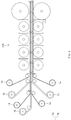
- the lamination device 100 comprises a transfer part 110 for transferring the electrode assembly 10, a heating roller part 120 for heating the electrode assembly 10 transferred by the transfer part 110, and a rolling roller 130 for rolling the electrode assembly 10 heated by the heating roller part 120 so that the electrode and the separator are bonded to each other.
- the transfer part comprises a transfer roller, and the transfer roller transfers the electrode assembly in a direction of the rolling roller 130 through rotation force thereof.
- the heating roller part is configured to directly press and simultaneously heating the electrode assembly transferred by the transfer part. That is, the heating roller part 120 directly conducts a heating source to the electrode assembly in a state in which the electrode assembly is pressed.
- the heating roller part 120 comprises a plurality of heating rollers 121 that press both surfaces of the electrode assembly 10 transferred to the transfer part 110 and simultaneously heat both the surfaces of the electrode assembly 10.
- the plurality of heating rollers 121 sequentially press the surface of the electrode assembly 10 and simultaneously heat the surface of the electrode assembly 10 so that the electrode assembly 10 gradually increases in temperature.
- the heating roller part 120 sequentially presses the same surface of the electrode assembly 10 by using the plurality of heating rollers 121 and simultaneously heats the surface of the electrode assembly 10 so that the surface temperature of the electrode assembly 10 gradually increases, thereby quickly heating the electrode assembly 10.
- the heating roller part 120 comprises four heating rollers that press the electrode 10 and simultaneously heat the electrode assembly 10.
- the four heating rollers comprise a first heating roller 121a for initially heating the electrode assembly 10, a second heating roller 121b for heating the electrode assembly 10 after heating the electrode assembly 10 through the first heating roller 121a, a third heating roller 121c for heating the electrode assembly 10 after heating the electrode assembly 10 through the second heating roller 121b, and a fourth heating roller 121d for finally heating the electrode assembly 10.
- the electrode assembly 10 when the surface of the electrode assembly 10 is heated by the first heating roller 121a, the electrode assembly 10 is heated at a first temperature, and then, when the surface of the electrode assembly 10, which has the first temperature, is heated by the second heating roller 121b, the electrode assembly 10 is heated at a second temperature higher than the first temperature. Then, when the surface of the electrode assembly 10, which has the second temperature, is heated by the third heating roller 121c, the electrode assembly 10 is heated at a third temperature higher than the second temperature, and then, when the surface of the electrode assembly 10, which has the third temperature, is heated by the fourth heating roller 121d, the electrode assembly 10 is heated at a fourth temperature higher than the third temperature. That is, as illustrated in FIG. 9 , the temperature of the electrode assembly 10 gradually increases from the first temperature to the fourth temperature.
- the heating roller part 120 may comprise the first to fourth heating rollers.
- the surface of the electrode assembly 10 may be sequentially pressed and simultaneously heated so that the electrode assembly 10 gradually increases in temperature.
- the embodiment of the present invention is not limited thereto.
- three or less heating rollers or four or more heating rollers may be provided to heat the electrode assembly 10.
- the plurality of heating rollers 121 of the heating roller part 120 may have the same size. Particularly, the plurality of heating rollers may have the same size, width, weight to uniformly press the entire surface of the electrode assembly 10, thereby uniformly heating the entire surface of the electrode assembly 10 without a temperature deviation.
- the plurality of heating rollers 121 of the heating roller part 120 may have the same heating temperature.
- the plurality of heating rollers 121 may have the same heating temperature and the same rotation rate to uniformly heat the entire surface of the electrode assembly 10 for the same time, thereby uniformly heating the entire surface of the electrode assembly 10 without the temperature deviation.
- the heating roller part 120 comprises a heating body 122 through which the electrode assembly 10 passes.
- the heating body 122 prevents the electrode assembly 10 from being changed in temperature by an external temperature change. That is, the heating body 122 comprises an accommodation space 122a through which the electrode assembly 10 passes.
- the plurality of heating rollers 121 that press the electrode assembly 10 and simultaneously heat the electrode assembly 10 are accommodated in the accommodation space 122a.
- the heating body 122 may press the electrode assembly 10 and simultaneously heat the electrode assembly 10 through the plurality of heating rollers 121 in the accommodation space 122a to effectively heat the electrode assembly 10.
- the electrode assembly 10 may be prevented from being rapidly changed in temperature by external environments.
- the heating body 122 further comprises an adjustment device 122b that allows the plurality of heating rollers 121 to descend or return to its original position toward the electrode assembly 10.
- the adjustment device 122b may allow the whole or any one or more of the plurality of heating rollers 121 to be in contact with or be separated from the electrode assembly 10.
- the number of heating rollers that press and heat the electrode assembly may be adjusted to effectively adjust the heating temperature of the electrode assembly 10.
- the heating roller part 120 further comprises a temperature sensor 123 that measures a temperature of the electrode assembly 10 passing through the plurality of heating rollers 121 and a controller 124 that generates a normal signal when the measured temperature value is within a set error range in comparison to a previously input set temperature value and outputs an abnormal signal when the measured temperature value is out of the set error range.
- the heating roller part 120 measures a temperature of the electrode assembly 10 passing through the plurality of heating rollers 121 by using the temperature sensor 123 to calculate a measured temperature value and then transmit the temperature value to the controller 124.
- the controller 124 compares the measured temperature value transmitted from the temperature sensor 123 with a previously input set temperature value.
- the measured temperature value is within the set temperature value, the normal signal is generated, and when the measured temperature value is greater or less than the set temperature value, the abnormal signal is generated. Accordingly, whether the heated electrode assembly is defective may be effectively detected.
- the temperature sensor 123 may be installed in each of the plurality of heating rollers that sequentially heat the surface of the electrode assembly to confirm and inspect all the temperatures of the electrode assembly heated by the plurality of heating rollers, thereby easily confirming a heating section in which the defective electrode assembly occurs.
- the heating roller part 120 may further comprise an adjustment member 125 that heats or cools the electrode assembly 10 passing through the plurality of heating rollers 121 to adjust the temperature of the electrode assembly 10 so that the temperature of the electrode assembly 10 is within an error range of the previously input set temperature value when the abnormal signal is output by the controller 124.
- the adjustment member 125 comprises an adjustment roller 125a that heats or cools the electrode assembly 10 so that the temperature of the electrode assembly 10 is within the error range of the previously input set temperature and an adjustment piece 125b that adjusts a temperature of the adjustment roller 125a so that the adjustment roller 125a heats or cools the electrode assembly 10.
- the adjustment member 125 may correct the temperature of the electrode assembly 10 that is inspected as defective so as to be within the set temperature value, thereby preventing the defective electrode assembly from being manufactured.
- the temperature of the electrode assembly which is inspected as defective, may be corrected to be within the set temperature value by adjusting a transfer speed of the electrode assembly. That is, when the abnormal signal is output, the controller 124 may accelerate or decelerate the transfer speed of the electrode assembly 10 through the transfer part 110. As a result, while the transfer speed of the electrode assembly 10 is adjusted, a contact time for which the electrode assembly 10 and the heating roller part 120 may be adjusted to adjust a heating temperature of the electrode assembly. That is to say, when the transfer speed of the electrode assembly decreases, the contact time between the electrode assembly 10 and the heating rollers may increase, and thus, the electrode assembly 10 may increase in temperature. On the other hand, when the transfer speed of the electrode assembly increases, the contact time between the electrode assembly and the heating rollers may decrease, and thus, the temperature of the electrode assembly may decrease.
- each of the plurality of heating rollers 121 has a size less than that of the rolling roller 130 to minimize an unheating time of the electrode assembly 10 due to the plurality of heating rollers 121, thereby more quickly heating the electrode assembly 10.
- a distance between each of the heating rollers 120 and the rolling roller may be minimized to minimize a transfer time that is taken to transfer the electrode assembly 10 from the heating roller to the rolling roller. Therefore, the electrode assembly 10 may be rolled in a state in which the temperature change of the electrode assembly 10 is minimized.
- a distance between an outer circumferential surface of the heating roller, which is disposed at a rolling roller-side, and an outer circumferential surface of the rolling roller may be 2 mm to 10 mm.
- a blocking plate 126 for preventing heat from being transferred may be provided between the plurality of heating rollers 121. That is, the blocking plate 126 may prevent a heat source from being transferred from the heating rollers 121 corresponding to each other, i.e., from being transferred from one heating roller 121 to the other heating roller 121. Therefore, each of the heating rollers may be prevented from being changed in temperature, and thus, the electrode assembly may be more accurately heated to increase in temperature.
- the blocking plate 126 for preventing heat from being transferred may be provided between the heating roller 121 and the rolling roller 130 to prevent the heat from being transferred between the heating roller 121 and the rolling roller 130, which correspond to each other. That is, the blocking plate 126 may prevent the heat source of the heating roller 121 from being transferred to the rolling roller 130 or prevent the heat source of the rolling roller 130 from being transferred to the heating roller 121.
- the heating roller or the rolling roller may press the electrode assembly in the state of being maintained at a predetermined temperature to more accurately heat the electrode assembly so that the electrode assembly increases in temperature.
- the rolling roller 130 rolls the electrode assembly 10 that is heated by the heating roller part 120 to bond the electrode 11 and the separator 12, which are provided in the electrode assembly 10, to each other.
- the lamination device 100 may directly conduct the heat source to the electrode assembly 10 to heat the electrode assembly10.
- the electrode assembly may be more quickly heated to improve heat transfer efficiency.
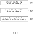
- a lamination method comprises a transfer step (S10) of transferring an electrode assembly 10 in which an electrode and a separator are laminated, a heating step (S20) of directly pressing the electrode assembly 10 transferred in the transfer step (S10) and simultaneously heating the electrode assembly 10, and a bonding step (S30) of rolling the electrode assembly heated in the heating step (S20) to bond the electrode and the separator to each other.
- the electrode assembly 10 is transferred to a rolling roller 130 by using a transfer roller.
- the heating step (S20) comprises a heating process (S21), a measuring process (S22), an inspection process (S23), and an adjustment process (S24).
- a surface of the electrode assembly 10 transferred in the transfer step (S10) is sequentially directly pressed and simultaneously heated through a plurality of heating rollers 121 so that the electrode assembly 10 gradually increases in temperature. That is, as the plurality of heating rollers 121 sequentially heats the surface of the electrode assembly 10, a surface temperature of the electrode assembly 10 may gradually increase. As a result, the temperature of the electrode assembly 10 may quickly increase to improve heat transfer efficiency.
- the temperature of the electrode assembly 10 heated in the heating process (S21) is measured to calculate a measured temperature value.
- the measured temperature value of the electrode assembly 10 which is measured in the measuring process (S22) is compared with an input set temperature value, and then, when the measured temperature value is within an error range, a normal signal is generated, and when the measured temperature value is out of the error range, an abnormal signal is output.
- the set temperature value may be 40°C to 70°C, and the error range may be ⁇ 2 to 4°C.
- the electrode assembly 10 is heated or cooled by the adjustment member 125 so that the temperature of the electrode assembly 10 is adjusted to be within the error range of the set temperature value. That is, the adjustment member 125 heats or cools an adjustment roller 125a through an adjustment piece 125b.
- the adjustment piece 125b heats the adjustment roller 125a to have a temperature greater than that of the electrode assembly 10 when the measured temperature value is less than the set temperature value and cools the adjustment roller 125a to have a temperature less than that of the electrode assembly 10 when the measured temperature value is greater than the set temperature value.
- the adjustment piece 125b heats or cools the adjustment roller 125a up to a previously input value according to a deviation between the measured temperature value and a set temperature value.
- the adjustment roller 125a heats or cools the electrode assembly 10 to adjust the temperature of the electrode assembly 10. Therefore, the temperature of the electrode assembly 10 is adjusted to be within the error range of the set temperature value.
- the electrode assembly 10 heated in the heating step (S20) is rolled by the rolling roller 130 to bond the electrode 11 and the separator 12 to each other.
- Secondary battery manufacturing equipment comprises the lamination device according to the foregoing first embodiment.
- the secondary battery manufacturing equipment comprises an electrode assembly manufacturing device 1 that manufactures an electrode assembly in which electrodes and separators are alternately laminated and a lamination device 100 through which the electrodes and the separators of the electrode assembly are bonded to each other.
- the lamination device comprises a transfer part that transfers the electrode assembly, a heating roller part that heats the electrode assembly transferred by the transfer part, and a rolling roller that rolls the electrode assembly heated by the heating roller part to bond the electrode to the separators.
- the lamination device may have the same constituent and function as the lamination device according to the first embodiment, and thus, their duplicated description will be omitted.
- the secondary battery manufacturing equipment may produce a secondary battery having high quality.
- the plurality of heating rollers 121 have sizes different from each other.
- the plurality of heating rollers 121 have sizes that gradually increase from the heating roller initially heating the electrode assembly 10 to the heating roller finally heating the electrode assembly. Accordingly, a contact area or pressing area between the heating roller and the electrode assembly may gradually increase, and thus, the temperature of the electrode assembly 10 may gradually increase, and the increase may be largely enlarged to increase in heating temperature of the electrode assembly.
- the lamination device according to the third embodiment of the present invention may be provided with the plurality of heating rollers 121 having the different sizes to significantly increase in temperature of the electrode assembly.
- the plurality of heating rollers 121 have heating temperatures different from each other.
- a heating temperature may gradually increase from a heating temperature at which the electrode assembly is initially heated to a heating temperature at which the electrode assembly is finally heated.
- a heating roller 121a that initially heats the electrode assembly is set to 50°C
- the next heating roller 121b is set to 60°C
- the one after the next heating roller 121c is set to 70°C
- the last heating roller 121d is set to 80°C.
- the electrode assembly may significantly increase in heating temperature.
- An electrode assembly is heated using a lamination device comprising a non-contact or non-pressurized heating device. That is, the non-contact or non-pressurized heating device uses a method in which heat is radiated to the electrode assembly.
- An electrode assembly is heated using a lamination device comprising a non-contact or directly pressurized heating device. That is, the electrode assembly is directly heated through the lamination device according to the first embodiment of the present invention. At this time, the lamination device according to the first embodiment of the present invention heats the electrode assembly by using four heating rollers.
- Comparative Example 1 and Manufacturing Example 1 the same electrode assembly is used, and the same pressure, the same heating time, and the same temperature are applied.
- the same temperature is 110°C.
- Example 2 a method in which an electrode assembly is directly heated by using a contact or directly pressurized heating device is performed. That is, the electrode assembly is directly heated through the lamination device according to the first embodiment of the present invention. At this time, the lamination device according to the first embodiment of the present invention heats the electrode assembly by using four heating rollers.
- heating rollers are set to 70°C, 90°C, and 100°C, and the experiment is performed three times.
- the plurality of heating rollers may be used to gradually increase in temperature of the electrode assembly.
- the electrode assembly transferred at a first speed is heated by using three heating rollers.
- the electrode assembly transferred at a second speed faster than the first speed is heated by using three heating rollers.
- the surface temperature of the electrode assembly decreases as the transfer speed of the electrode assembly increases. Accordingly, when the transfer speed of the electrode assembly is adjusted, it may be seen that the heating temperature of the electrode assembly is adjusted.
Landscapes
- Chemical & Material Sciences (AREA)
- Chemical Kinetics & Catalysis (AREA)
- Electrochemistry (AREA)
- General Chemical & Material Sciences (AREA)
- Engineering & Computer Science (AREA)
- Manufacturing & Machinery (AREA)
- Secondary Cells (AREA)
- Battery Electrode And Active Subsutance (AREA)
Abstract
Description
- The present application claims the benefit of the priority of
Korean Patent Application No. 10-2018-0154583, filed on December 4, 2018 - The present invention relates to a lamination device and method and secondary battery manufacturing equipment comprising the lamination device, and more particularly, to a lamination device and method, which directly heat an electrode assembly, in which electrodes and separators are alternately laminated, to improve heat transfer efficiency, and secondary battery manufacturing equipment comprising the lamination device.
- In general, secondary batteries refer to chargeable and dischargeable batteries, unlike primary batteries that are not chargeable. The secondary batteries are being widely used in the high-tech electronic fields such as mobile phones, notebook computers, and camcorders.
- Such a secondary battery comprises an electrode assembly, in which an electrode and a separator are alternately laminated, and a case accommodating the electrode assembly. A method for manufacturing the secondary battery comprises a process of manufacturing electrodes, a process of alternately laminating the manufactured electrodes and separators to manufacture an electrode assembly, a lamination process of thermally bonding the electrode assembly, a process of accommodating the electrode assembly into a case to manufacture an unfinished secondary battery, and an activation process of charging and discharging the unfinished secondary battery.
- In the lamination process, a heating device having a heating section in which the electrode assembly is heated and a rolling device that rolls the heated electrode assembly are used.
- However, in the lamination process, since the heating device transfers radiant heat, it takes a long time to heat the electrode assembly. Particularly, since the heating section of the heating device has to be largely secured, there is a problem that efficiency is significantly reduced.
- The present invention has been invented to solve the above problems, and the present invention comprises a heating device provided with a heating roller that directly heats an electrode assembly. The heating roller is provided in plurality to improve heat transfer efficiency, and significantly reduce an installation section of the heating device. Particularly, an object of the present invention is to provide a lamination device and method, in which a temperature of the electrode assembly gradually increases through the plurality of heating rollers, and thus, the temperature of the electrode assembly increases without deforming and damaging an electrode or a separator, which are provided in the electrode assembly, and secondary battery manufacturing equipment comprising the lamination device.
- A lamination device of the present invention for achieving the above objects is configured to bond an electrode and a separator of an electrode assembly to each other and comprise: a transfer part configured to transfer the electrode assembly; a heating roller part configured to heat the electrode assembly transferred by the transfer part; and a rolling roller configured to roll the electrode assembly heated by the heating roller part so that the electrode and the separator are bonded to each other, wherein the heating roller part comprises a plurality of heating rollers configured to press and heat a surface of the electrode assembly at the same time, and the plurality of rollers sequentially press the surface of the electrode assembly and simultaneously heat the surface of the electrode assembly so that the electrode assembly gradually increases in temperature.
- The plurality of heating rollers may have the same size or different sizes.
- When the plurality of heating rollers have the different sizes, the heating rollers may have sizes that gradually increase from the heating roller that initially heats the electrode assembly to the heating roller that finally heats the electrode assembly.
- The plurality of heating rollers may have the same heating temperature or different heating temperatures.
- When the plurality of heating rollers have the different heating temperatures, the heating temperature may gradually increase from the heating roller that initially heats the electrode assembly to the heating roller that finally heats the electrode assembly.
- The heating roller part may comprise a heating body having an accommodation space through which the electrode assembly passes, and the plurality of heating rollers may be provided in the accommodation space of the heating body to press the electrode assembly passing through the accommodation space and simultaneously heat the electrode assembly.
- The heating roller part may further comprise: a temperature sensor configured to measure a temperature of the electrode assembly passing through the plurality of heating rollers; and a controller configured to generate a normal signal when the measured temperature value is within a set error range in comparison to a previously input set temperature value and output an abnormal signal when the measured temperature value is out of the set error range.
- The heating roller part may further comprise an adjustment member configured to heat or cool the electrode assembly passing through the plurality of heating rollers so as to adjust the temperature of the electrode assembly so that the temperature of the electrode assembly is within the error range of the previously input set temperature value when the abnormal signal is output by the controller.
- When the abnormal signal is output, the controller may accelerate or decelerate a transfer speed of the electrode assembly through the transfer part to adjust a contact time between the electrode assembly and the heating roller part, thereby adjusting a heating temperature of the electrode assembly.
- A blocking plate configured to prevent heat from being transferred may be provided between the plurality of heating rollers.
- A lamination method comprises: a transfer step (S10) of transferring an electrode assembly in which an electrode and a separator are laminated; a heating step (S20) of pressing and heating the electrode assembly transferred in the transfer step (S10) at the same time; and a bonding step (S30) of rolling the electrode assembly heated in the heating step (S20) to bond the electrode and the separator to each other, wherein, the heating step (S20) comprises a heating process (S21) in which a surface of the electrode assembly is sequentially pressed and simultaneously heated through a plurality of heating rollers so that the
electrode assembly 10 gradually increases in temperature. - The heating step (S20) may further comprise: a measuring process (S22) of measuring the temperature of the electrode assembly heated in the heating process (S21); and an inspection process (S23) of generating a normal signal if a measured temperature value is within an error range and outputting an abnormal signal if the measured temperature value is out of the error range when the measured temperature value of the electrode assembly, which is measured in the measuring process (S22), is compared with an input set temperature value.
- The heating step (S20) may further comprise an inspection process (S23) of heating or cooling the electrode assembly passing through the plurality of heating rollers to adjust the temperature of the electrode assembly to be within the error range of the set temperature value when the abnormal signal is output in the inspection process (S23).
- In the heating step (S20), a transfer speed of the electrode assembly transferred in the transfer step (S10) may be adjusted together with the adjusting process (S24) so that a heating temperature of the electrode assembly is within the error range of the set temperature value.
- The heating step (S20) may further comprises an adjustment process (S24) of heating or cooling the electrode assembly passing through the plurality of heating rollers to adjust the temperature of the electrode assembly to be within the error range of the set temperature value when the abnormal signal is output in the inspection process (S23).
- In the heating step (S20), a transfer speed of the electrode assembly transferred in the transfer step (S10) may be adjusted together with the adjusting process (S24) so that a contact time between the electrode assembly and each of the heating rollers increases or decreases to allow a heating temperature of the electrode assembly to be within the error range of the set temperature value.
- Secondary battery manufacturing equipment comprises: an electrode assembly manufacturing device for manufacturing an electrode assembly by alternately laminating an electrode and a separator; and a lamination device for bonding the electrode and the separator of the electrode assembly to each other, wherein the lamination device comprises: a transfer part configured to transfer the electrode assembly; a heating roller part configured to heat the electrode assembly transferred by the transfer part; and a rolling roller configured to roll the electrode assembly heated by the heating roller part so that the electrode and the separator are bonded to each other, wherein the heating roller part comprises a plurality of heating rollers configured to press and heat a surface of the electrode assembly at the same time, and the plurality of rollers sequentially press the surface of the electrode assembly and simultaneously heat the surface of the electrode assembly so that the electrode assembly gradually increases in temperature.
- The lamination device of the present invention may comprises the heating member comprising the plurality of heating rollers that heat the surface of the electrode assembly while pressing the surface of the electrode assembly. Therefore, the surface of the electrode assembly may be sequentially pressed and heated to gradually increase in temperature, thereby improving the heat transfer efficiency. Particularly, the heating section of the electrode assembly may be minimized, and the electrode and the separator, which are provided in the electrode assembly, may be prevented from being deformed and damaged to manufacture the electrode assembly having the high quality.
- Particularly, the lamination device may comprise the plurality of heating rollers to prevent the electrode assembly from being twisted during the transfer of the electrode assembly, thereby preventing the defective electrode assembly from being manufactured.
-
-
FIG. 1 is a side view of a lamination device according to a first embodiment of the present invention. -
FIG. 2 is a side view of a heating roller part that further comprises a heating body, a temperature sensor, a controller, and an adjustment member in the lamination device according to the first embodiment. -
FIG. 3 is a flowchart of a lamination method according to a first embodiment of the present invention. -
FIG. 4 is a side view of secondary battery manufacturing equipment according to a second embodiment of the present invention. -
FIG. 5 is a side view of a lamination device according to a third embodiment of the present invention. -
FIG. 6 is a side view of a lamination device according to a fourth embodiment of the present invention. -
FIG. 7 is a graph illustrating Experimental Example 1 according to the present invention. -
FIG. 8 is a table summarizing experimental results of Experimental Example 1 according to the present invention. -
FIG. 9 is a graph illustrating Experimental Example 2 according to the present invention. -
FIG. 10 is a graph illustrating Experimental Example 3 according to the present invention. - Hereinafter, embodiments of the present invention will be described in detail with reference to the accompanying drawings in such a manner that the technical idea of the present invention may easily be carried out by a person with ordinary skill in the art to which the invention pertains. The present invention may, however, be embodied in different forms and should not be construed as limited to the embodiments set forth herein. In the drawings, anything unnecessary for describing the present invention will be omitted for clarity, and also like reference numerals in the drawings denote like elements.
- An
electrode assembly 10 comprises electrodes and separators. That is, referring toFIG. 1 , theelectrode assembly 10 has a structure in which a plurality ofelectrodes 11 and a plurality ofseparators 12, each of which has a long sheet shape, are alternately laminated. - The plurality of
electrodes 11 may comprise a positive electrode and a negative electrode, and theelectrode assembly 10 may have a structure in which a positive electrode, a separator, a negative electrode, a separator, and a positive electrode are sequentially laminated. - The
electrode assembly 10 having the above-described structure increase in bonding force through thelamination device 100 according to the first embodiment of the present invention. - Here, the
lamination device 100 according to the first embodiment of the present invention may directly press and simultaneously heat theelectrode assembly 10 to sequentially press the surface of the electrode assembly and simultaneously heat the surface of theelectrode assembly 10 so that theelectrode assembly 10 gradually increases in temperature. Therefore, the heat transfer efficiency of theelectrode assembly 10 may be improved, and particularly, theelectrode 11 and theseparator 12, which are provided in theelectrode assembly 10, may be quickly heated without being deformed and damaged. - Referring to
FIG. 1 , thelamination device 100 according to the first embodiment of the present invention may further comprise theprotective film 20 for protecting the surface of theelectrode assembly 10 because theelectrode assembly 10 is directly pressed and simultaneously heated. Theprotective film 20 may be attached to theelectrode assembly 10 and then be removed from theelectrode assembly 10 when the rolling of theelectrode assembly 10 is completed. - Hereinafter, the lamination device according to the first embodiment of the present invention will be described in more detail.
- As illustrated in
FIG. 1 , thelamination device 100 according to the first embodiment of the present invention comprises atransfer part 110 for transferring theelectrode assembly 10, aheating roller part 120 for heating theelectrode assembly 10 transferred by thetransfer part 110, and a rollingroller 130 for rolling theelectrode assembly 10 heated by theheating roller part 120 so that the electrode and the separator are bonded to each other. - The transfer part comprises a transfer roller, and the transfer roller transfers the electrode assembly in a direction of the rolling
roller 130 through rotation force thereof. - The heating roller part is configured to directly press and simultaneously heating the electrode assembly transferred by the transfer part. That is, the
heating roller part 120 directly conducts a heating source to the electrode assembly in a state in which the electrode assembly is pressed. - That is, the
heating roller part 120 comprises a plurality ofheating rollers 121 that press both surfaces of theelectrode assembly 10 transferred to thetransfer part 110 and simultaneously heat both the surfaces of theelectrode assembly 10. The plurality ofheating rollers 121 sequentially press the surface of theelectrode assembly 10 and simultaneously heat the surface of theelectrode assembly 10 so that theelectrode assembly 10 gradually increases in temperature. - That is to say, the
heating roller part 120 sequentially presses the same surface of theelectrode assembly 10 by using the plurality ofheating rollers 121 and simultaneously heats the surface of theelectrode assembly 10 so that the surface temperature of theelectrode assembly 10 gradually increases, thereby quickly heating theelectrode assembly 10. - For example, referring to
FIG. 1 , theheating roller part 120 comprises four heating rollers that press theelectrode 10 and simultaneously heat theelectrode assembly 10. The four heating rollers comprise afirst heating roller 121a for initially heating theelectrode assembly 10, asecond heating roller 121b for heating theelectrode assembly 10 after heating theelectrode assembly 10 through thefirst heating roller 121a, athird heating roller 121c for heating theelectrode assembly 10 after heating theelectrode assembly 10 through thesecond heating roller 121b, and afourth heating roller 121d for finally heating theelectrode assembly 10. - In the
heating roller part 120 having the above-described configuration, when the surface of theelectrode assembly 10 is heated by thefirst heating roller 121a, theelectrode assembly 10 is heated at a first temperature, and then, when the surface of theelectrode assembly 10, which has the first temperature, is heated by thesecond heating roller 121b, theelectrode assembly 10 is heated at a second temperature higher than the first temperature. Then, when the surface of theelectrode assembly 10, which has the second temperature, is heated by thethird heating roller 121c, theelectrode assembly 10 is heated at a third temperature higher than the second temperature, and then, when the surface of theelectrode assembly 10, which has the third temperature, is heated by thefourth heating roller 121d, theelectrode assembly 10 is heated at a fourth temperature higher than the third temperature. That is, as illustrated inFIG. 9 , the temperature of theelectrode assembly 10 gradually increases from the first temperature to the fourth temperature. - Thus, the
heating roller part 120 may comprise the first to fourth heating rollers. As a result, the surface of theelectrode assembly 10 may be sequentially pressed and simultaneously heated so that theelectrode assembly 10 gradually increases in temperature. - Although the four heating rollers are provided in this embodiment of the present invention, the embodiment of the present invention is not limited thereto. For example, three or less heating rollers or four or more heating rollers may be provided to heat the
electrode assembly 10. - The plurality of
heating rollers 121 of theheating roller part 120 may have the same size. Particularly, the plurality of heating rollers may have the same size, width, weight to uniformly press the entire surface of theelectrode assembly 10, thereby uniformly heating the entire surface of theelectrode assembly 10 without a temperature deviation. - The plurality of
heating rollers 121 of theheating roller part 120 may have the same heating temperature. Particularly, the plurality ofheating rollers 121 may have the same heating temperature and the same rotation rate to uniformly heat the entire surface of theelectrode assembly 10 for the same time, thereby uniformly heating the entire surface of theelectrode assembly 10 without the temperature deviation. - As illustrated in
FIG. 2 , theheating roller part 120 comprises aheating body 122 through which theelectrode assembly 10 passes. Theheating body 122 prevents theelectrode assembly 10 from being changed in temperature by an external temperature change. That is, theheating body 122 comprises an accommodation space 122a through which theelectrode assembly 10 passes. The plurality ofheating rollers 121 that press theelectrode assembly 10 and simultaneously heat theelectrode assembly 10 are accommodated in the accommodation space 122a. - Thus, the
heating body 122 may press theelectrode assembly 10 and simultaneously heat theelectrode assembly 10 through the plurality ofheating rollers 121 in the accommodation space 122a to effectively heat theelectrode assembly 10. Particularly, theelectrode assembly 10 may be prevented from being rapidly changed in temperature by external environments. - The
heating body 122 further comprises anadjustment device 122b that allows the plurality ofheating rollers 121 to descend or return to its original position toward theelectrode assembly 10. Theadjustment device 122b may allow the whole or any one or more of the plurality ofheating rollers 121 to be in contact with or be separated from theelectrode assembly 10. Thus, the number of heating rollers that press and heat the electrode assembly may be adjusted to effectively adjust the heating temperature of theelectrode assembly 10. - The
heating roller part 120 further comprises a temperature sensor 123 that measures a temperature of theelectrode assembly 10 passing through the plurality ofheating rollers 121 and acontroller 124 that generates a normal signal when the measured temperature value is within a set error range in comparison to a previously input set temperature value and outputs an abnormal signal when the measured temperature value is out of the set error range. - That is, the
heating roller part 120 measures a temperature of theelectrode assembly 10 passing through the plurality ofheating rollers 121 by using the temperature sensor 123 to calculate a measured temperature value and then transmit the temperature value to thecontroller 124. Thus, thecontroller 124 compares the measured temperature value transmitted from the temperature sensor 123 with a previously input set temperature value. Here, when the measured temperature value is within the set temperature value, the normal signal is generated, and when the measured temperature value is greater or less than the set temperature value, the abnormal signal is generated. Accordingly, whether the heated electrode assembly is defective may be effectively detected. - The temperature sensor 123 may be installed in each of the plurality of heating rollers that sequentially heat the surface of the electrode assembly to confirm and inspect all the temperatures of the electrode assembly heated by the plurality of heating rollers, thereby easily confirming a heating section in which the defective electrode assembly occurs.
- The
heating roller part 120 may further comprise anadjustment member 125 that heats or cools theelectrode assembly 10 passing through the plurality ofheating rollers 121 to adjust the temperature of theelectrode assembly 10 so that the temperature of theelectrode assembly 10 is within an error range of the previously input set temperature value when the abnormal signal is output by thecontroller 124. - That is, the
adjustment member 125 comprises anadjustment roller 125a that heats or cools theelectrode assembly 10 so that the temperature of theelectrode assembly 10 is within the error range of the previously input set temperature and anadjustment piece 125b that adjusts a temperature of theadjustment roller 125a so that theadjustment roller 125a heats or cools theelectrode assembly 10. - As described above, the
adjustment member 125 may correct the temperature of theelectrode assembly 10 that is inspected as defective so as to be within the set temperature value, thereby preventing the defective electrode assembly from being manufactured. - According to another embodiment, the temperature of the electrode assembly, which is inspected as defective, may be corrected to be within the set temperature value by adjusting a transfer speed of the electrode assembly. That is, when the abnormal signal is output, the
controller 124 may accelerate or decelerate the transfer speed of theelectrode assembly 10 through thetransfer part 110. As a result, while the transfer speed of theelectrode assembly 10 is adjusted, a contact time for which theelectrode assembly 10 and theheating roller part 120 may be adjusted to adjust a heating temperature of the electrode assembly. That is to say, when the transfer speed of the electrode assembly decreases, the contact time between theelectrode assembly 10 and the heating rollers may increase, and thus, theelectrode assembly 10 may increase in temperature. On the other hand, when the transfer speed of the electrode assembly increases, the contact time between the electrode assembly and the heating rollers may decrease, and thus, the temperature of the electrode assembly may decrease. - In the
heating roller part 120, each of the plurality ofheating rollers 121 has a size less than that of the rollingroller 130 to minimize an unheating time of theelectrode assembly 10 due to the plurality ofheating rollers 121, thereby more quickly heating theelectrode assembly 10. Particularly, a distance between each of theheating rollers 120 and the rolling roller may be minimized to minimize a transfer time that is taken to transfer theelectrode assembly 10 from the heating roller to the rolling roller. Therefore, theelectrode assembly 10 may be rolled in a state in which the temperature change of theelectrode assembly 10 is minimized. Particularly, a distance between an outer circumferential surface of the heating roller, which is disposed at a rolling roller-side, and an outer circumferential surface of the rolling roller may be 2 mm to 10 mm. Thus, an interference between the heating roller and the rolling roller is prevented from occurring, and also, the electrode assembly may be rolled in the state in which the temperature change of the electrode assembly is minimized. - A blocking
plate 126 for preventing heat from being transferred may be provided between the plurality ofheating rollers 121. That is, the blockingplate 126 may prevent a heat source from being transferred from theheating rollers 121 corresponding to each other, i.e., from being transferred from oneheating roller 121 to theother heating roller 121. Therefore, each of the heating rollers may be prevented from being changed in temperature, and thus, the electrode assembly may be more accurately heated to increase in temperature. - When the
heating roller part 120 does not comprise theheating body 122, the blockingplate 126 for preventing heat from being transferred may be provided between theheating roller 121 and the rollingroller 130 to prevent the heat from being transferred between theheating roller 121 and the rollingroller 130, which correspond to each other. That is, the blockingplate 126 may prevent the heat source of theheating roller 121 from being transferred to the rollingroller 130 or prevent the heat source of the rollingroller 130 from being transferred to theheating roller 121. Thus, the heating roller or the rolling roller may press the electrode assembly in the state of being maintained at a predetermined temperature to more accurately heat the electrode assembly so that the electrode assembly increases in temperature. - The rolling
roller 130 rolls theelectrode assembly 10 that is heated by theheating roller part 120 to bond theelectrode 11 and theseparator 12, which are provided in theelectrode assembly 10, to each other. - Thus, the
lamination device 100 according to the first embodiment of the present invention may directly conduct the heat source to theelectrode assembly 10 to heat the electrode assembly10. Thus, the electrode assembly may be more quickly heated to improve heat transfer efficiency. - Hereinafter, a lamination method according to the first embodiment of the present invention will be described.
- As illustrated in
FIG. 3 , a lamination method according to the first embodiment of the present invention comprises a transfer step (S10) of transferring anelectrode assembly 10 in which an electrode and a separator are laminated, a heating step (S20) of directly pressing theelectrode assembly 10 transferred in the transfer step (S10) and simultaneously heating theelectrode assembly 10, and a bonding step (S30) of rolling the electrode assembly heated in the heating step (S20) to bond the electrode and the separator to each other. - In the transfer step (S10), the
electrode assembly 10 is transferred to a rollingroller 130 by using a transfer roller. - The heating step (S20) comprises a heating process (S21), a measuring process (S22), an inspection process (S23), and an adjustment process (S24).
- In the heating process (S21), a surface of the
electrode assembly 10 transferred in the transfer step (S10) is sequentially directly pressed and simultaneously heated through a plurality ofheating rollers 121 so that theelectrode assembly 10 gradually increases in temperature. That is, as the plurality ofheating rollers 121 sequentially heats the surface of theelectrode assembly 10, a surface temperature of theelectrode assembly 10 may gradually increase. As a result, the temperature of theelectrode assembly 10 may quickly increase to improve heat transfer efficiency. - In the measuring process (S22), the temperature of the
electrode assembly 10 heated in the heating process (S21) is measured to calculate a measured temperature value. - In the inspection process (S23), the measured temperature value of the
electrode assembly 10, which is measured in the measuring process (S22), is compared with an input set temperature value, and then, when the measured temperature value is within an error range, a normal signal is generated, and when the measured temperature value is out of the error range, an abnormal signal is output. - The set temperature value may be 40°C to 70°C, and the error range may be ± 2 to 4°C.
- In the adjustment process (S24), when the abnormal signal is output by the inspection process (S23), the
electrode assembly 10 is heated or cooled by theadjustment member 125 so that the temperature of theelectrode assembly 10 is adjusted to be within the error range of the set temperature value. That is, theadjustment member 125 heats or cools anadjustment roller 125a through anadjustment piece 125b. Here, theadjustment piece 125b heats theadjustment roller 125a to have a temperature greater than that of theelectrode assembly 10 when the measured temperature value is less than the set temperature value and cools theadjustment roller 125a to have a temperature less than that of theelectrode assembly 10 when the measured temperature value is greater than the set temperature value. Here, theadjustment piece 125b heats or cools theadjustment roller 125a up to a previously input value according to a deviation between the measured temperature value and a set temperature value. When the temperature of theadjustment roller 125a is adjusted, theadjustment roller 125a heats or cools theelectrode assembly 10 to adjust the temperature of theelectrode assembly 10. Therefore, the temperature of theelectrode assembly 10 is adjusted to be within the error range of the set temperature value. - In the rolling step (S30), the
electrode assembly 10 heated in the heating step (S20) is rolled by the rollingroller 130 to bond theelectrode 11 and theseparator 12 to each other. - Hereinafter, in descriptions of another embodiment of the present invention, constituents having the same function as the above-mentioned embodiment have been given the same reference numeral in the drawings, and thus duplicated description will be omitted.
- Secondary battery manufacturing equipment according to a second embodiment of the present invention comprises the lamination device according to the foregoing first embodiment.
- That is, the secondary battery manufacturing equipment according to the second embodiment of the present invention comprises an electrode
assembly manufacturing device 1 that manufactures an electrode assembly in which electrodes and separators are alternately laminated and alamination device 100 through which the electrodes and the separators of the electrode assembly are bonded to each other. The lamination device comprises a transfer part that transfers the electrode assembly, a heating roller part that heats the electrode assembly transferred by the transfer part, and a rolling roller that rolls the electrode assembly heated by the heating roller part to bond the electrode to the separators. - Here, the lamination device may have the same constituent and function as the lamination device according to the first embodiment, and thus, their duplicated description will be omitted.
- Thus, the secondary battery manufacturing equipment according to the second embodiment of the present invention may produce a secondary battery having high quality.
- As illustrated in
FIG. 5 , a lamination device according to a third embodiment of the present invention comprises aheating roller part 120 comprising a plurality ofheating rollers 121. Here, the plurality ofheating rollers 121 have sizes different from each other. - For example, referring to
FIG. 5 , the plurality ofheating rollers 121 have sizes that gradually increase from the heating roller initially heating theelectrode assembly 10 to the heating roller finally heating the electrode assembly. Accordingly, a contact area or pressing area between the heating roller and the electrode assembly may gradually increase, and thus, the temperature of theelectrode assembly 10 may gradually increase, and the increase may be largely enlarged to increase in heating temperature of the electrode assembly. - Thus, the lamination device according to the third embodiment of the present invention may be provided with the plurality of
heating rollers 121 having the different sizes to significantly increase in temperature of the electrode assembly. - As illustrated in
FIG. 6 , a lamination device according to a fourth embodiment of the present invention comprises aheating roller part 120 comprising a plurality ofheating rollers 121. Here, the plurality ofheating rollers 121 have heating temperatures different from each other. - That is, in the lamination device according to the fourth embodiment of the present invention, when the plurality of heating rollers have heating temperatures different from each other, a heating temperature may gradually increase from a heating temperature at which the electrode assembly is initially heated to a heating temperature at which the electrode assembly is finally heated.
- For example, a
heating roller 121a that initially heats the electrode assembly is set to 50°C, thenext heating roller 121b is set to 60°C, the one after thenext heating roller 121c is set to 70°C, and thelast heating roller 121d is set to 80°C. As described above, when theelectrode assembly 10 is heated through the heating roller of which a temperature is set, a small temperature change of theelectrode assembly 10 occurs at the initial stage, and a large temperature change of theelectrode assembly 10 occurs at the last stage. Thus, theelectrode assembly 10 may increase up to the set temperature. - Thus, in the lamination device according to the fourth embodiment of the present invention, the electrode assembly may significantly increase in heating temperature.
- An electrode assembly is heated using a lamination device comprising a non-contact or non-pressurized heating device. That is, the non-contact or non-pressurized heating device uses a method in which heat is radiated to the electrode assembly.
- An electrode assembly is heated using a lamination device comprising a non-contact or directly pressurized heating device. That is, the electrode assembly is directly heated through the lamination device according to the first embodiment of the present invention. At this time, the lamination device according to the first embodiment of the present invention heats the electrode assembly by using four heating rollers.
- Here, in Comparative Example 1 and Manufacturing Example 1, the same electrode assembly is used, and the same pressure, the same heating time, and the same temperature are applied. The same temperature is 110°C.
- As the results of measuring the temperature of the electrode assembly heated through Comparative Example and Manufacturing Example 1, a graph of
FIG. 7 may be obtained. - Referring to the graph of
FIG. 7 , when measuring a time for which the temperature of the electrode assembly heated through Comparative Example and Manufacturing Example 1reaches 60°C, it takes 4.25s for the temperature of the electrode assembly to reach 60°C in Comparative Example, and it takes 0.44s for the temperature of the electrode assembly to reach 60°C in Manufacturing Example 1. - Therefore, as the results of comparing Manufacturing Example 1 with Comparative Example, the result table as shown in
FIG. 8 may be obtained. Thus, it is seen that the temperature quickly increases in Manufacturing Example 1 in comparison to Comparative Example. Therefore, heat transfer efficiency may be significantly improved. - In Manufacturing Example 2, a method in which an electrode assembly is directly heated by using a contact or directly pressurized heating device is performed. That is, the electrode assembly is directly heated through the lamination device according to the first embodiment of the present invention. At this time, the lamination device according to the first embodiment of the present invention heats the electrode assembly by using four heating rollers.
- In particular, four heating rollers are set to 70°C, 90°C, and 100°C, and the experiment is performed three times.
- In Manufacturing Example 2, when the experiment is performed three times at temperature of 70°C, 90°C, and 100°C, as illustrated in
FIG. 9 , a graph in which the temperature of the electrode assembly gradually increase may be obtained. - That is, as illustrated in
Figure 9 , when all the four heating rollers are set to 70°C, it is seen that a surface temperature of the electrode assembly gradually increases to temperatures of 36°C, 42°C, 46°C, and 49°C. When all the four heating rollers are set to 90°C, it is seen that a surface temperature of the electrode assembly gradually increases to temperatures of 39°C, 47°C, 53°C, and 57°C. When all the four heating rollers are set to 100°C, it is seen that a surface temperature of the electrode assembly gradually increases to temperatures of 43°C, 56°C, 65°C, and 69°C. - Therefore, as the results of the experiment as described above, the plurality of heating rollers may be used to gradually increase in temperature of the electrode assembly.
- In Manufacturing Examples 3 and 4, a method in which an electrode assembly is directly heated by using a contact or directly pressurized heating device is performed. That is, the electrode assembly is directly heated through the lamination device according to the first embodiment of the present invention.
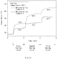
- Here, in Manufacturing Example 3, the electrode assembly transferred at a first speed is heated by using three heating rollers. In Manufacturing Example 4, the electrode assembly transferred at a second speed faster than the first speed is heated by using three heating rollers.
- Here, all the three heating rollers described in Manufacturing Examples 3 and 4 are set to a temperature of 100°C.
- As the results of the experiment as described above, as illustrated in
FIG 10 , in Manufacturing Example 3, it is seen that a surface temperature of the electrode assembly increases to temperature of 43°C, 56°C, and 65°C. In Manufacturing Example 4, it is seen that the surface temperature of the electrode assembly increases to temperature of 35°C, 43°C, and 52°C. - Therefore, referring to Manufacturing Examples 3 and 4, it may be seen that the surface temperature of the electrode assembly decreases as the transfer speed of the electrode assembly increases. Accordingly, when the transfer speed of the electrode assembly is adjusted, it may be seen that the heating temperature of the electrode assembly is adjusted.
- Accordingly, the scope of the present invention is defined by the appended claims more than the foregoing description and the exemplary embodiments described therein. Various modifications made within the meaning of an equivalent of the claims of the invention and within the claims are to be regarded to be in the scope of the present invention.
Claims (15)
- A lamination device for bonding an electrode and a separator of an electrode assembly to each other, the lamination device comprising:a transfer part configured to transfer the electrode assembly;a heating roller part configured to heat the electrode assembly transferred by the transfer part; anda rolling roller configured to roll the electrode assembly heated by the heating roller part so that the electrode and the separator are bonded to each other,wherein the heating roller part comprises a plurality of heating rollers configured to press and heat a surface of the electrode assembly at the same time, andthe plurality of rollers sequentially press the surface of the electrode assembly and simultaneously heat the surface of the electrode assembly so that the electrode assembly gradually increases in temperature.
- The lamination device of claim 1, wherein the plurality of heating rollers have the same size or different sizes.
- The lamination device of claim 2, wherein, when the plurality of heating rollers have the different sizes, the heating rollers have sizes that gradually increase from the heating roller that initially heats the electrode assembly to the heating roller that finally heats the electrode assembly.
- The lamination device of claim 1, wherein the plurality of heating rollers have the same heating temperature or different heating temperatures.
- The lamination device of claim 4, wherein, when the plurality of heating rollers have the different heating temperatures, the heating temperature gradually increases from the heating roller that initially heats the electrode assembly to the heating roller that finally heats the electrode assembly.
- The lamination device of claim 1, wherein the heating roller part comprises a heating body having an accommodation space through which the electrode assembly passes, and
the plurality of heating rollers are provided in the accommodation space of the heating body to press the electrode assembly passing through the accommodation space and simultaneously heat the electrode assembly. - The lamination device of claim 6, wherein the heating roller part further comprises:a temperature sensor configured to measure a temperature of the electrode assembly passing through the plurality of heating rollers; anda controller configured to generate a normal signal when the measured temperature value is within a set error range in comparison to a previously input set temperature value and output an abnormal signal when the measured temperature value is out of the set error range.
- The lamination device of claim 7, wherein the heating roller part further comprises an adjustment member configured to heat or cool the electrode assembly passing through the plurality of heating rollers so as to adjust the temperature of the electrode assembly so that the temperature of the electrode assembly is within the error range of the previously input set temperature value when the abnormal signal is output by the controller.
- The lamination device of claim 7, wherein, when the abnormal signal is output, the controller accelerates or decelerates a transfer speed of the electrode assembly through the transfer part to adjust a contact time between the electrode assembly and the heating roller part, thereby adjusting a heating temperature of the electrode assembly.
- The lamination device of claim 1, wherein a blocking plate configured to prevent heat from being transferred is provided between the plurality of heating rollers.
- A lamination method comprising:a transfer step (S10) of transferring an electrode assembly in which an electrode and a separator are laminated;a heating step (S20) of pressing and heating the electrode assembly transferred in the transfer step (S10) at the same time; anda bonding step (S30) of rolling the electrode assembly heated in the heating step (S20) to bond the electrode and the separator to each other,wherein, the heating step (S20) comprises a heating process (S21) in which a surface of the electrode assembly is sequentially pressed and simultaneously heated through a plurality of heating rollers so that the electrode assembly 10 gradually increases in temperature.
- The lamination method of claim 11, wherein the heating step (S20) further comprises:a measuring process (S22) of measuring the temperature of the electrode assembly heated in the heating process (S21); andan inspection process (S23) of generating a normal signal if a measured temperature value is within an error range and outputting an abnormal signal if the measured temperature value is out of the error range when the measured temperature value of the electrode assembly, which is measured in the measuring process (S22), is compared with an input set temperature value.
- The lamination method of claim 12, wherein the heating step (S20) further comprises an adjustment process (S24) of heating or cooling the electrode assembly passing through the plurality of heating rollers to adjust the temperature of the electrode assembly to be within the error range of the set temperature value when the abnormal signal is output in the inspection process (S23).
- The lamination method of claim 13, wherein, in the heating step (S20), a transfer speed of the electrode assembly transferred in the transfer step (S10) is adjusted together with the adjusting process (S24) so that a heating temperature of the electrode assembly is within the error range of the set temperature value.
- Secondary battery manufacturing equipment comprising:an electrode assembly manufacturing device for manufacturing an electrode assembly by alternately laminating an electrode and a separator; anda lamination device for bonding the electrode and the separator of the electrode assembly to each other,wherein the lamination device comprises:a transfer part configured to transfer the electrode assembly;a heating roller part configured to heat the electrode assembly transferred by the transfer part; anda rolling roller configured to roll the electrode assembly heated by the heating roller part so that the electrode and the separator are bonded to each other,wherein the heating roller part comprises a plurality of heating rollers configured to press and heat a surface of the electrode assembly at the same time, andthe plurality of rollers sequentially press the surface of the electrode assembly and simultaneously heat the surface of the electrode assembly so that the electrode assembly gradually increases in temperature.
Applications Claiming Priority (2)
| Application Number | Priority Date | Filing Date | Title |
|---|---|---|---|
| KR1020180154583A KR102516224B1 (en) | 2018-12-04 | 2018-12-04 | Lamination apparatus and method, producing facility of secondary battery including the same |
| PCT/KR2019/016393 WO2020116846A1 (en) | 2018-12-04 | 2019-11-26 | Lamination apparatus and method, and equipment for manufacturing secondary battery comprising same |
Publications (2)
| Publication Number | Publication Date |
|---|---|
| EP3866243A1 true EP3866243A1 (en) | 2021-08-18 |
| EP3866243A4 EP3866243A4 (en) | 2022-01-26 |
Family
ID=70975484
Family Applications (1)
| Application Number | Title | Priority Date | Filing Date |
|---|---|---|---|
| EP19894268.2A Pending EP3866243A4 (en) | 2018-12-04 | 2019-11-26 | LAMINATING APPARATUS AND METHOD, AND SECONDARY BATTERY MANUFACTURING EQUIPMENT COMPRISING THEM |
Country Status (6)
| Country | Link |
|---|---|
| US (1) | US12463303B2 (en) |
| EP (1) | EP3866243A4 (en) |
| JP (1) | JP7251030B2 (en) |
| KR (1) | KR102516224B1 (en) |
| CN (1) | CN113614965B (en) |
| WO (1) | WO2020116846A1 (en) |
Cited By (2)
| Publication number | Priority date | Publication date | Assignee | Title |
|---|---|---|---|---|
| WO2024088827A3 (en) * | 2022-10-25 | 2024-06-20 | Körber Technologies Gmbh | Laminating device for laminating multilayer endless webs for producing energy cells |
| EP4629307A1 (en) * | 2024-04-02 | 2025-10-08 | Samsung Sdi Co., Ltd. | Secondary battery manufacturing apparatus |
Families Citing this family (17)
| Publication number | Priority date | Publication date | Assignee | Title |
|---|---|---|---|---|
| KR102580441B1 (en) * | 2019-03-06 | 2023-09-20 | 주식회사 엘지에너지솔루션 | The Apparatus And The Method For Manufacturing Cell |
| WO2022014911A1 (en) * | 2020-07-17 | 2022-01-20 | 주식회사 엘지에너지솔루션 | Separator sealing device and unit cell manufacturing device using same |
| KR102782614B1 (en) * | 2020-07-17 | 2025-03-19 | 주식회사 엘지에너지솔루션 | Separator sealing device and unit cell manufacturing device using the same |
| KR102926748B1 (en) | 2020-08-21 | 2026-02-11 | 주식회사 엘지에너지솔루션 | Method for rolling electrode |
| KR102770379B1 (en) * | 2020-09-28 | 2025-02-21 | 주식회사 엘지에너지솔루션 | Laminator for manufacturing unit structures with improved adhesion |
| CN116325256B (en) * | 2020-12-23 | 2025-09-30 | 株式会社Lg新能源 | Method and apparatus for manufacturing unit cells |
| KR102795061B1 (en) * | 2020-12-23 | 2025-04-16 | 주식회사 엘지에너지솔루션 | Manufacturing method and apparatus for unit cell |
| KR102953705B1 (en) * | 2021-01-22 | 2026-04-16 | 주식회사 엘지에너지솔루션 | Apparatus and method for manufacturing secondary battery |
| CN112820930B (en) * | 2021-02-09 | 2024-06-04 | 无锡先导智能装备股份有限公司 | Lamination machine |
| KR102557822B1 (en) * | 2021-03-17 | 2023-07-21 | (주)나노테크 | Lamination apparatus for manufacturing a secondary cell battery |
| CN112838260B (en) * | 2021-03-23 | 2023-01-24 | 蜂巢能源科技有限公司 | A stacking device |
| US12244038B2 (en) | 2021-07-09 | 2025-03-04 | Lg Energy Solution, Ltd. | Electrode assembly |
| EP4258400B1 (en) * | 2021-10-26 | 2025-11-26 | LG Energy Solution, Ltd. | Electrode assembly lamination roller |
| KR102991876B1 (en) | 2021-11-16 | 2026-07-15 | 주식회사 엘지에너지솔루션 | Electrode assembly, lithium secondary battery containing the same and manufacturing method thereof |
| CN115829906B (en) * | 2022-04-18 | 2024-01-30 | 宁德时代新能源科技股份有限公司 | Method, device and system for defect detection of cathode plates of composite tapes |
| KR102586978B1 (en) * | 2023-04-25 | 2023-10-10 | 유호전기공업주식회사 | A portable catalytic heating system capable of thermoelectric power generation, electric vehicle equipped with the system and an operating method for the same |
| KR20260007901A (en) * | 2024-07-08 | 2026-01-15 | 주식회사 엘지에너지솔루션 | Heating apparatus and lamination facility include the same |
Family Cites Families (24)
| Publication number | Priority date | Publication date | Assignee | Title |
|---|---|---|---|---|
| JPH11176473A (en) * | 1997-12-10 | 1999-07-02 | Toshiba Battery Co Ltd | Equipment for manufacturing electrode elements for polymer batteries |
| JP2003323072A (en) * | 2002-04-30 | 2003-11-14 | Brother Ind Ltd | Fixing device and image forming apparatus |
| TWI232833B (en) * | 2002-08-27 | 2005-05-21 | Primax Electronics Ltd | Hot laminating apparatus with thermos mask |
| KR100546878B1 (en) | 2004-07-02 | 2006-01-26 | 주식회사 엘티케이 | Method and apparatus for manufacturing electrode tab attachment body for secondary battery |
| JP2008311012A (en) * | 2007-06-13 | 2008-12-25 | Toyota Motor Corp | Production apparatus and production method for electrode material assembly for fuel cell, fuel cell |
| KR101090601B1 (en) | 2009-06-09 | 2011-12-08 | 주식회사 협진아이엔씨 | Gas diffusion layer carbon substrate of Polymer Electrolyte Membrane type fuel cell and its manufacturing method, its manufacturing system |
| KR101355834B1 (en) | 2010-12-02 | 2014-01-28 | 주식회사 엘지화학 | Device for Laminating Electrode Assembly Used in Manufacturing Secondary Battery |
| JP5633348B2 (en) * | 2010-12-06 | 2014-12-03 | 新東工業株式会社 | Laminated joined body manufacturing apparatus and laminated joined body manufacturing method |
| GB2494918A (en) * | 2011-09-23 | 2013-03-27 | Tiko Corp Ltd | Thermal laminator |
| JP2013122831A (en) | 2011-12-09 | 2013-06-20 | Automotive Energy Supply Corp | Apparatus and method of manufacturing electrode group, and method of manufacturing battery |
| US9793525B2 (en) * | 2012-10-09 | 2017-10-17 | Johnson Battery Technologies, Inc. | Solid-state battery electrodes |
| US9466825B2 (en) * | 2012-11-21 | 2016-10-11 | Nagano Automation Co., Ltd. | Apparatus that sandwiches electrode sheet with separators |
| JP6036324B2 (en) * | 2013-01-21 | 2016-11-30 | 株式会社豊田自動織機 | Storage device manufacturing apparatus and manufacturing method |
| JP5699348B2 (en) | 2013-11-11 | 2015-04-08 | 大日本印刷株式会社 | Manufacturing apparatus and manufacturing method for membrane catalyst layer assembly, and manufacturing apparatus and manufacturing method for membrane electrode assembly |
| WO2015122594A1 (en) * | 2014-02-14 | 2015-08-20 | 주식회사 엘지화학 | Battery cell comprising wrinkle preventing member |
| KR101764469B1 (en) * | 2014-10-02 | 2017-08-02 | 주식회사 엘지화학 | Secondary Battery Electrode System And Method |
| JP5717913B1 (en) * | 2014-12-11 | 2015-05-13 | 株式会社日立パワーソリューションズ | Thickness gauge and roll press machine provided with the thickness gauge |
| KR101725904B1 (en) * | 2015-01-26 | 2017-04-11 | 주식회사 엘지화학 | Electrode Drying Device Including Hybrid Drying Oven |
| KR102037841B1 (en) * | 2015-09-24 | 2019-10-30 | 주식회사 엘지화학 | Manufacturing device and manufacturing method for secondary battery |
| JP6541531B2 (en) * | 2015-09-28 | 2019-07-10 | 株式会社Screenホールディングス | Apparatus and method for manufacturing membrane / catalyst layer assembly |
| CN106222068A (en) | 2016-08-22 | 2016-12-14 | 上海交通大学 | Miniature PCR system of capillary glass tube and preparation method thereof |
| KR101835372B1 (en) * | 2016-08-25 | 2018-03-09 | 김태완 | Laminating device for secondary cell |
| CN108199092B (en) | 2017-12-06 | 2020-04-07 | 浙江衡远新能源科技有限公司 | Lithium battery winding device and winding process |
| US10773504B2 (en) * | 2018-06-22 | 2020-09-15 | Apple Inc. | Systems and methods for manufacturing battery cells |
-
2018
- 2018-12-04 KR KR1020180154583A patent/KR102516224B1/en active Active
-
2019
- 2019-11-26 CN CN201980074098.6A patent/CN113614965B/en active Active
- 2019-11-26 EP EP19894268.2A patent/EP3866243A4/en active Pending
- 2019-11-26 JP JP2021525838A patent/JP7251030B2/en active Active
- 2019-11-26 WO PCT/KR2019/016393 patent/WO2020116846A1/en not_active Ceased
- 2019-11-26 US US17/294,578 patent/US12463303B2/en active Active
Cited By (2)
| Publication number | Priority date | Publication date | Assignee | Title |
|---|---|---|---|---|
| WO2024088827A3 (en) * | 2022-10-25 | 2024-06-20 | Körber Technologies Gmbh | Laminating device for laminating multilayer endless webs for producing energy cells |
| EP4629307A1 (en) * | 2024-04-02 | 2025-10-08 | Samsung Sdi Co., Ltd. | Secondary battery manufacturing apparatus |
Also Published As
| Publication number | Publication date |
|---|---|
| JP2022512072A (en) | 2022-02-02 |
| US20220006161A1 (en) | 2022-01-06 |
| JP7251030B2 (en) | 2023-04-04 |
| US12463303B2 (en) | 2025-11-04 |
| CN113614965B (en) | 2023-10-31 |
| EP3866243A4 (en) | 2022-01-26 |
| WO2020116846A1 (en) | 2020-06-11 |
| KR102516224B1 (en) | 2023-03-30 |
| CN113614965A (en) | 2021-11-05 |
| KR20200067575A (en) | 2020-06-12 |
Similar Documents
| Publication | Publication Date | Title |
|---|---|---|
| US12463303B2 (en) | Lamination device and method and secondary battery manufacturing equipment comprising lamination device | |
| EP3902049B1 (en) | Lamination apparatus and method for secondary battery | |
| KR102104319B1 (en) | Heater press apparature included in folding system for heat pressurizing to terrace of secondary battery cell | |
| EP3525278A1 (en) | Lamination device for secondary battery | |
| KR102759173B1 (en) | Manufacturing equipment and manufacturing method of electrode assembly | |
| US8377582B2 (en) | Cooling apparatus of a battery module | |
| US20200331187A1 (en) | Apparatus and Method for Manufacturing Pouch and Method for Manufacturing Secondary Battery | |
| KR102795945B1 (en) | Defective Inspection Device of Pouch-type Battery Cell | |
| KR101838334B1 (en) | A Manufacturing Method for Curved Cell and a Curved Cell thereby | |
| US20210050626A1 (en) | Method for Manufacturing Electrode Assembly and Method for Manufacturing Secondary Battery | |
| US20210036356A1 (en) | Electrode Sheet Rolling Apparatus, Guide Roll System Used Therein, and Method of Winding Electrode Sheet Using the Same | |
| US20230125899A1 (en) | Electrode Manufacturing Apparatus Including Electrode Alignment Unit and Electrode Assembly Manufacturing Apparatus | |
| CN115995616A (en) | Tab correction method and tab correction device | |
| KR102845972B1 (en) | Manufacturing method and apparatus for electrode | |
| EP4477390B1 (en) | Secondary battery sealing device | |
| US20250201892A1 (en) | Device and Method for Manufacturing Secondary Battery | |
| KR20210120731A (en) | Lamination apparatus and method for secondary battery | |
| KR20200093956A (en) | Heating unit for electrode assembly and lamination apparatus and method including the same | |
| KR102196264B1 (en) | Device and method for detecting charge current and discharge current of battery | |
| US12576626B2 (en) | Laminator for manufacture of unit structural bodies with increased force of adhesion | |
| KR20230070867A (en) | Secondary cell rolling system and secondary cell defect prediction function method using the same | |
| KR20250041899A (en) | Electrode assembly manufacturing equipment and manufacturing method for electrode assembly | |
| US20250253306A1 (en) | Electrode foil edge tensioning | |
| CN121620815A (en) | Battery manufacturing apparatus and battery manufacturing method using the same | |
| KR20230087989A (en) | Notching device and controlling method thereof |
Legal Events
| Date | Code | Title | Description |
|---|---|---|---|
| STAA | Information on the status of an ep patent application or granted ep patent |
Free format text: STATUS: THE INTERNATIONAL PUBLICATION HAS BEEN MADE |
|
| PUAI | Public reference made under article 153(3) epc to a published international application that has entered the european phase |
Free format text: ORIGINAL CODE: 0009012 |
|
| STAA | Information on the status of an ep patent application or granted ep patent |
Free format text: STATUS: REQUEST FOR EXAMINATION WAS MADE |
|
| 17P | Request for examination filed |
Effective date: 20210512 |
|
| AK | Designated contracting states |
Kind code of ref document: A1 Designated state(s): AL AT BE BG CH CY CZ DE DK EE ES FI FR GB GR HR HU IE IS IT LI LT LU LV MC MK MT NL NO PL PT RO RS SE SI SK SM TR |
|
| A4 | Supplementary search report drawn up and despatched |
Effective date: 20211223 |
|
| RIC1 | Information provided on ipc code assigned before grant |
Ipc: H01M 10/615 20140101ALI20211217BHEP Ipc: H01M 10/48 20060101ALI20211217BHEP Ipc: H01M 10/04 20060101AFI20211217BHEP |
|
| DAV | Request for validation of the european patent (deleted) | ||
| DAX | Request for extension of the european patent (deleted) | ||
| RAP3 | Party data changed (applicant data changed or rights of an application transferred) |
Owner name: LG ENERGY SOLUTION, LTD. |