KR20200093956A - Heating unit for electrode assembly and lamination apparatus and method including the same - Google Patents
Heating unit for electrode assembly and lamination apparatus and method including the same Download PDFInfo
- Publication number
- KR20200093956A KR20200093956A KR1020190011335A KR20190011335A KR20200093956A KR 20200093956 A KR20200093956 A KR 20200093956A KR 1020190011335 A KR1020190011335 A KR 1020190011335A KR 20190011335 A KR20190011335 A KR 20190011335A KR 20200093956 A KR20200093956 A KR 20200093956A
- Authority
- KR
- South Korea
- Prior art keywords
- electrode assembly
- heating
- heating unit
- disposed
- line
- Prior art date
Links
Images


Classifications
-
- H—ELECTRICITY
- H01—ELECTRIC ELEMENTS
- H01M—PROCESSES OR MEANS, e.g. BATTERIES, FOR THE DIRECT CONVERSION OF CHEMICAL ENERGY INTO ELECTRICAL ENERGY
- H01M10/00—Secondary cells; Manufacture thereof
- H01M10/04—Construction or manufacture in general
- H01M10/0404—Machines for assembling batteries
-
- H—ELECTRICITY
- H01—ELECTRIC ELEMENTS
- H01M—PROCESSES OR MEANS, e.g. BATTERIES, FOR THE DIRECT CONVERSION OF CHEMICAL ENERGY INTO ELECTRICAL ENERGY
- H01M10/00—Secondary cells; Manufacture thereof
- H01M10/04—Construction or manufacture in general
- H01M10/0413—Large-sized flat cells or batteries for motive or stationary systems with plate-like electrodes
-
- H—ELECTRICITY
- H01—ELECTRIC ELEMENTS
- H01M—PROCESSES OR MEANS, e.g. BATTERIES, FOR THE DIRECT CONVERSION OF CHEMICAL ENERGY INTO ELECTRICAL ENERGY
- H01M10/00—Secondary cells; Manufacture thereof
- H01M10/04—Construction or manufacture in general
- H01M10/0436—Small-sized flat cells or batteries for portable equipment
-
- Y—GENERAL TAGGING OF NEW TECHNOLOGICAL DEVELOPMENTS; GENERAL TAGGING OF CROSS-SECTIONAL TECHNOLOGIES SPANNING OVER SEVERAL SECTIONS OF THE IPC; TECHNICAL SUBJECTS COVERED BY FORMER USPC CROSS-REFERENCE ART COLLECTIONS [XRACs] AND DIGESTS
- Y02—TECHNOLOGIES OR APPLICATIONS FOR MITIGATION OR ADAPTATION AGAINST CLIMATE CHANGE
- Y02E—REDUCTION OF GREENHOUSE GAS [GHG] EMISSIONS, RELATED TO ENERGY GENERATION, TRANSMISSION OR DISTRIBUTION
- Y02E60/00—Enabling technologies; Technologies with a potential or indirect contribution to GHG emissions mitigation
- Y02E60/10—Energy storage using batteries
-
- Y—GENERAL TAGGING OF NEW TECHNOLOGICAL DEVELOPMENTS; GENERAL TAGGING OF CROSS-SECTIONAL TECHNOLOGIES SPANNING OVER SEVERAL SECTIONS OF THE IPC; TECHNICAL SUBJECTS COVERED BY FORMER USPC CROSS-REFERENCE ART COLLECTIONS [XRACs] AND DIGESTS
- Y02—TECHNOLOGIES OR APPLICATIONS FOR MITIGATION OR ADAPTATION AGAINST CLIMATE CHANGE
- Y02P—CLIMATE CHANGE MITIGATION TECHNOLOGIES IN THE PRODUCTION OR PROCESSING OF GOODS
- Y02P70/00—Climate change mitigation technologies in the production process for final industrial or consumer products
- Y02P70/50—Manufacturing or production processes characterised by the final manufactured product
Abstract
Description
본 발명은 전극조립체 가열유닛, 그를 포함하는 라미네이션장치 및 방법에 관한 것으로서, 특히 전극조립체 가열시 전극조립체가 틀어지거나 또는 전극조립체에 포함된 전극 및 분리막이 틀어지는 현상을 방지한 전극조립체 가열유닛, 그를 포함하는 라미네이션장치 및 방법에 관한 것이다.The present invention relates to an electrode assembly heating unit, a lamination apparatus and method comprising the same, in particular, the electrode assembly heating unit, which prevents the electrode assembly from being distorted or the electrode and the separator included in the electrode assembly when the electrode assembly is heated, the same It relates to a lamination apparatus and method comprising.
일반적으로 이차전지(secondary battery)는 충전이 불가능한 일차 전지와는 달리 충전 및 방전이 가능한 전지를 말하며, 이러한 이차 전지는 폰, 노트북 컴퓨터 및 캠코더 등의 첨단 전자 기기 분야에서 널리 사용되고 있다.In general, a secondary battery refers to a battery that can be charged and discharged, unlike a primary battery that cannot be charged. Such secondary batteries are widely used in the fields of high-tech electronic devices such as phones, notebook computers, and camcorders.
이와 같은 이차전지는 전극과 분리막이 교대로 적층된 전극조립체, 상기 전극조립체를 수용하는 케이스를 포함한다. 그리고 상기한 이차전지의 제조방법은 전극을 제조하는 공정, 전극과 분리막을 교대로 적층하여 전극조립체를 제조하는 공정, 상기 전극조립체를 열접합하는 라미네이션 공정, 상기 전극조립체를 케이스에 수용하여 미완성 이차전지를 제조하는 공정, 상기 미완성 이차전지를 충방전하여 완제품 이차전지를 제조하는 활성화공정을 포함한다.Such a secondary battery includes an electrode assembly in which electrodes and separators are alternately stacked, and a case accommodating the electrode assembly. In addition, the manufacturing method of the secondary battery includes a process of manufacturing an electrode, a process of manufacturing an electrode assembly by alternately stacking electrodes and a separator, a lamination process of thermally bonding the electrode assembly, and receiving the electrode assembly in a case to complete an unfinished secondary. It includes a process for manufacturing a battery, and an activation process for charging and discharging the unfinished secondary battery to produce a finished product secondary battery.
그리고 상기 라미네이션 공정은 전극조립체를 이송하는 이송단계, 이송되는 전극조립체의 양쪽 표면에 제1 및 제2 보호필름을 각각 배치하는 필름배치단계, 상기 제1 및 제2 보호필름이 배치된 전극조립체를 가열하는 가열단계, 가열된 전극조립체를 압연하여 접합하는 접합단계를 포함한다.And the lamination process is a transfer step of transferring the electrode assembly, a film arrangement step of disposing the first and second protective films on both surfaces of the transferred electrode assembly, respectively, and the electrode assembly on which the first and second protective films are disposed. And a heating step of heating, and a bonding step of rolling and bonding the heated electrode assembly.
여기서 상기한 가열단계는 제1 및 제2 보호필름 사이에 배치된 전극조립체를 가열하면서 이송하게 되는데, 이때 전극조립체는 별도로 고정해 주는 장치가 없는 상태로 이송되며, 이에 따라 상기 제1 및 제2 보호필름 사이에서 전극조립체가 틀어지거나 또는 전극조립체에 포함된 전극 및 분리막의 정렬이 틀어질 수 있고, 그 결과 제품 불량이 발생할 수 있는 문제점이 있었다.Here, the above-described heating step is transferred while heating the electrode assembly disposed between the first and second protective films, wherein the electrode assembly is transferred in the absence of a separate fixing device, and accordingly the first and second There is a problem in that the electrode assembly may be misaligned between the protective films or the alignment of the electrodes and the separators included in the electrode assembly may be misaligned, resulting in product defects.
본 발명은 상기와 같은 문제점을 해결하기 위해 발명된 것으로, 본 발명은 전극조립체를 가열함과 동시에 이송할 때 상기 전극조립체를 가압한 상태로 이송하며, 이에 따라 전극조립체의 고정력을 높일 수 있고, 그 결과 전극조립체가 틀어지거나 또는 전극조립체에 포함된 전극 및 분리막의 정렬이 틀어지는 것을 방지할 수 있는 전극조립체 가열유닛, 그를 포함하는 라미네이션장치 및 방법을 제공하는 것을 목적으로 한다.The present invention was invented to solve the above problems, and the present invention transfers the electrode assembly in a pressurized state when the electrode assembly is heated and transported, thereby increasing the fixing force of the electrode assembly, As a result, an object of the present invention is to provide an electrode assembly heating unit, a lamination apparatus and method comprising the same, which can prevent the electrode assembly from being distorted or the alignment of the electrode and the separator included in the electrode assembly is misaligned.
상기와 같은 목적을 달성하기 위한 본 발명의 제1 실시예에 따른 전극조립체 가열유닛은 전극조립체를 가열함과 동시에 이송하는 제1 가열부를 포함하며, 상기 제1 가열부는, 상기 전극조립체의 이송방향과 직교되는 제1 라인 상에 배치되고, 상기 전극조립체를 1차 가열하는 제1 가열부재; 및 상기 제1 라인 상에 배치되고, 상기 제1 가열부재에 의해 가열중인 상기 전극조립체를 가압한 상태로 이송하는 제1 이송부재를 포함할 수 있다.The electrode assembly heating unit according to the first embodiment of the present invention for achieving the above object includes a first heating unit for heating and simultaneously transferring the electrode assembly, the first heating unit, the transfer direction of the electrode assembly A first heating member disposed on a first line orthogonal to and primary heating the electrode assembly; And a first transfer member disposed on the first line and transferring the electrode assembly being heated by the first heating member in a pressurized state.
상기 제1 가열부재는, 상기 제1 라인 상에 2개 이상 배치되고, 상기 제1 이송부재는, 상기 제1 라인 상에 위치한 2개 이상의 상기 제1 가열부재들 사이에 배치될 수 있다.Two or more first heating members may be disposed on the first line, and the first transfer member may be disposed between two or more first heating members located on the first line.
상기 제1 이송부재는, 2개의 제1 롤러와, 상기 2개의 제1 롤러에 감기고 상기 제1 롤러 회전시 상기 전극조립체를 가압한 상태로 강제로 이송하는 제1 벨트를 포함할 수 있다.The first transfer member may include two first rollers, and a first belt wound around the two first rollers and forcibly transferring the electrode assembly while pressing the first roller.
상기 제1 가열부는, 상기 제1 벨트에 의해 가압되는 상기 전극조립체의 표면을 가열하는 제1 보조가열부재를 더 포함할 수 있다.The first heating unit may further include a first auxiliary heating member for heating the surface of the electrode assembly pressed by the first belt.
상기 제1 가열부를 통과한 상기 전극조립체의 이송방향과 직교되는 제2 라인 상에 배치되고, 상기 전극조립체를 가열함과 동시에 이송하는 제2 가열부를 더 포함할 수 있다.It may be disposed on a second line orthogonal to the transfer direction of the electrode assembly passing through the first heating unit, and may further include a second heating unit for heating and transferring the electrode assembly.
상기 제2 가열부는, 상기 제2 라인 상에 배치되되, 상기 제1 이송부재를 통과한 상기 전극조립체를 가열하는 제2 가열부재; 및 상기 제2 라인 상에 배치되되, 상기 제1 가열부재를 통과한 가열된 상기 전극조립체를 가압한 상태로 이송하는 제2 이송부재를 포함할 수 있다.The second heating unit is disposed on the second line, a second heating member for heating the electrode assembly passing through the first transfer member; And a second transfer member disposed on the second line and transferring the heated electrode assembly passing through the first heating member in a pressurized state.
상기 제2 이송부재는, 2개의 제2 롤러와, 상기 2개의 제2 롤러에 감기고 상기 2개의 제2 롤러 회전시 상기 전극조립체를 가압한 상태로 강제로 이송하는 제2 벨트를 포함할 수 있다.The second transfer member may include two second rollers, and a second belt wound around the two second rollers and forcibly transferring the electrode assembly in a pressurized state when the two second rollers are rotated. .
상기 제2 가열부는, 상기 제2 벨트에 의해 가압된 상기 전극조립체의 표면을 가열하는 제2 보조가열부재를 더 포함할 수 있다.The second heating unit may further include a second auxiliary heating member that heats the surface of the electrode assembly pressed by the second belt.
상기 제1 라인 상에 배치된 제1 가열부재 및 제1 이송부재를 포함한 제1 가열부의 전폭과, 상기 제2 라인 상에 배치된 제2 가열부재 및 제2 이송부재를 포함한 제2 가열부의 전폭은 동일하되, 상기 제2 가열부재의 전폭은 상기 제1 이송부재의 전폭 보다 크게 형성되고, 상기 제2 이송부재의 전폭은 상기 제1 가열부재의 전폭 보다 작게 형성될 수 있다.The full width of the first heating unit including the first heating member and the first transfer member disposed on the first line, and the full width of the second heating unit including the second heating member and the second transfer member disposed on the second line. Is the same, the full width of the second heating member is formed larger than the full width of the first transfer member, the full width of the second transfer member may be formed smaller than the full width of the first heating member.
한편, 본 발명의 제2 실시예에 따른 라미네이션장치는 전극조립체를 공급하는 공급유닛; 상기 공급유닛에 의해 공급된 상기 전극조립체를 가열함과 동시에 가압한 상태로 이송하는 전극조립체 가열유닛; 상기 전극조립체 가열유닛에 의해 가열된 상기 전극조립체를 압연하여 접합하는 라미네이션유닛을 포함하며, 상기 전극조립체 가열유닛은, 전극조립체를 가열함과 동시에 이송하는 제1 가열부를 포함하고, 상기 제1 가열부는, 상기 전극조립체의 이송방향과 직교되는 제1 라인 상에 배치되고, 상기 전극조립체를 1차 가열하는 제1 가열부재; 및 상기 제1 라인 상에 배치되고, 상기 제1 가열부재에 의해 가열중인 상기 전극조립체를 가압한 상태로 이송하는 제1 이송부재를 포함할 수 있다.On the other hand, the lamination apparatus according to the second embodiment of the present invention includes a supply unit for supplying an electrode assembly; An electrode assembly heating unit for heating the electrode assembly supplied by the supply unit and transferring it in a pressurized state at the same time; And a lamination unit for rolling and bonding the electrode assembly heated by the electrode assembly heating unit, wherein the electrode assembly heating unit includes a first heating unit that simultaneously heats and transfers the electrode assembly, and the first heating. The unit may include: a first heating member disposed on a first line orthogonal to a transfer direction of the electrode assembly and primarily heating the electrode assembly; And a first transfer member disposed on the first line and transferring the electrode assembly being heated by the first heating member in a pressurized state.
상기 전극조립체 가열유닛은, 상기 제1 가열부를 통과한 상기 전극조립체의 이송방향과 직교되는 제2 라인 상에 배치되고, 상기 전극조립체를 가열함과 동시에 이송하는 제2 가열부를 더 포함할 수 있다.The electrode assembly heating unit may further include a second heating unit disposed on a second line orthogonal to the transfer direction of the electrode assembly passing through the first heating unit and simultaneously heating and transferring the electrode assembly. .
한편, 본 발명의 제2 실시예에 따른 라미네이션장치를 이용한 라미네이션방법은 전극조립체를 공급하는 전극조립체 공급단계(S10); 상기 전극조립체 공급단계(S10)에 의해 공급된 전극조립체를 전극조립체 가열유닛으로 가열함과 동시에 가압한 상태로 이송하는 전극조립체 가열단계(S20); 및 상기 전극조립체 가열단계(S20)에 의해 가열 및 이송된 전극조립체를 압연하여 접합하는 전극조립체 접합단계(S30)를 포함할 수 있다.Meanwhile, a lamination method using a lamination apparatus according to a second embodiment of the present invention includes an electrode assembly supply step (S10) of supplying an electrode assembly; An electrode assembly heating step (S20) of heating the electrode assembly supplied by the electrode assembly supply step (S10) with an electrode assembly heating unit and transferring it in a pressurized state; And it may include an electrode assembly bonding step (S30) of rolling and bonding the electrode assembly heated and transferred by the electrode assembly heating step (S20).
상기 전극조립체 가열단계(S20)는, 상기 전극조립체 공급단계(S10)에 의해 공급된 전극조립체를 상기 전극조립체 가열유닛의 제1 가열부로 가열함과 동시에 가압한 상태로 이송하는 제1 가열공정을 포함하고, 상기 제1 가열공정에서 상기 제1 가열부는 상기 전극조립체의 이송방향과 직교되는 제1 라인 상에 배치되면서 상기 전극조립체를 1차 가열하는 제1 가열부재와, 상기 제1 라인 상에 배치되면서 상기 제1 가열부재에 의해 가열중인 상기 전극조립체를 이송하는 제1 이송부재를 포함할 수 있다.In the electrode assembly heating step (S20), the electrode assembly supplied by the electrode assembly supply step (S10) is heated to a first heating unit of the electrode assembly heating unit and simultaneously transferred to a first heating process. Included, in the first heating process, the first heating unit is disposed on a first line orthogonal to the transfer direction of the electrode assembly, and a first heating member for primary heating of the electrode assembly, and on the first line The arrangement may include a first transfer member for transferring the electrode assembly being heated by the first heating member.
상기 전극조립체 가열단계(S20)는, 상기 제1 가열공정을 통과한 전극조립체를 상기 전극조립체 가열유닛의 제2 가열부로 가열함과 동시에 가압한 상태로 이송하는 제2 가열공정을 더 포함하고, 상기 제2 가열공정에서 상기 제2 가열부는 상기 제1 가열부를 통과한 상기 전극조립체의 이송방향과 직교되는 제2 라인 상에 배치되면서 상기 제1 이송부재를 통과하는 상기 전극조립체의 표면을 가열하는 제2 가열부재와, 상기 제2 라인 상에 배치되면서 상기 제2 가열부재를 통과한 상기 전극조립체를 가압한 상태로 이송하는 제2 이송부재를 포함할 수 있다.The electrode assembly heating step (S20) further includes a second heating process for heating the electrode assembly that has passed through the first heating process to the second heating unit of the electrode assembly heating unit and transferring it under pressure. In the second heating process, the second heating part is disposed on a second line orthogonal to the transfer direction of the electrode assembly passing through the first heating part to heat the surface of the electrode assembly passing through the first transfer member. A second heating member and a second conveying member disposed on the second line and transferring the electrode assembly passing through the second heating member in a pressurized state may be included.
한편, 본 발명의 제3 실시예에 따른 전극조립체 가열유닛은 전극조립체를 가열함과 동시에 이송하는 제1 가열부를 포함하며, 상기 제1 가열부는, 상기 전극조립체의 이송방향과 직교되는 제1 라인 상에 배치되고, 상기 전극조립체를 1차 가열하는 제1 가열부재; 및 상기 제1 라인 상에 배치되고, 상기 제1 가열부재에 의해 가열중인 상기 전극조립체를 가압한 상태로 이송하는 제1 이송부재를 포함하되, 상기 제1 가열부재는, 상기 제1 라인 상에 1개가 배치되고, 상기 제1 이송부재는, 상기 제1 라인 상에 위치한 1개의 상기 제1 가열부재 양쪽 측부에 각각 배치될 수 있다.On the other hand, the electrode assembly heating unit according to the third embodiment of the present invention includes a first heating unit for heating and transferring the electrode assembly, and the first heating unit is a first line orthogonal to the transfer direction of the electrode assembly. A first heating member disposed on and primarily heating the electrode assembly; And a first transfer member disposed on the first line and transferring the electrode assembly being heated by the first heating member in a pressurized state, wherein the first heating member is on the first line. One is disposed, and the first transfer member may be disposed on both sides of one of the first heating members located on the first line.
본 발명의 전극조립체 가열유닛은 전극조립체의 이송방향과 직교되는 제1 라인 상에 배치되는 제1 가열부재와 제1 이송부재를 포함하되, 상기 제1 가열부재는 제1 라인을 통과하는 전극조립체를 가열하고, 상기 제1 이송부재는 제1 라인을 통과하는 가열중인 전극조립체를 가압한 상태로 이송하는 것에 특징을 가진다. 이와 같은 특징으로 인해 전극조립체의 고정력을 높일 수 있고, 이에 따라 전극조립체를 가열할 때 전극조립체가 틀어지거나 또는 전극조립체에 포함된 전극 및 분리막의 정렬이 틀어지는 것을 방지할 수 있으며, 그 결과 제품불량이 발생하는 것을 방지할 수 있다.The electrode assembly heating unit of the present invention includes a first heating member and a first transfer member disposed on a first line orthogonal to a transfer direction of the electrode assembly, wherein the first heating member is an electrode assembly passing through the first line. Heating, and the first transfer member is characterized in that the electrode assembly under heating passing through the first line is transferred under pressure. Due to these features, it is possible to increase the fixing force of the electrode assembly, and accordingly, when heating the electrode assembly, it is possible to prevent the electrode assembly from being distorted or the alignment of the electrodes and the separators included in the electrode assembly is distorted, resulting in product defects. This can be prevented from occurring.
또한, 본 발명의 전극조립체 가열유닛은 상기 전극조립체의 이송방향과 직교되는 제2 라인 상에 배치되는 제2 가열부재와 제2 이송부재를 포함하되, 상기 제2 가열부재는 제1 이송부재를 통과한 전극조립체의 표면을 가열하고, 상기 제2 이송부재는 제1 가열부재를 통과한 전극조립체의 표면을 가압한 상태로 이송하는 것에 특징을 가진다. 이와 같은 특징으로 인해 전극조립체의 표면 전체를 안정적으로 가열함과 동시에 이송할 수 있고, 특히 전극조립체를 가열할 때 전극조립체가 틀어지거나 또는 전극조립체에 포함된 전극 및 분리막의 정렬이 틀어지는 것을 방지할 수 있다.In addition, the electrode assembly heating unit of the present invention includes a second heating member and a second transfer member disposed on a second line orthogonal to the transfer direction of the electrode assembly, wherein the second heating member comprises a first transfer member. The surface of the electrode assembly that has passed is heated, and the second transfer member is characterized by transferring the surface of the electrode assembly that has passed through the first heating member in a pressurized state. Due to these features, the entire surface of the electrode assembly can be stably heated and transported at the same time. In particular, when heating the electrode assembly, it is possible to prevent the electrode assembly from being distorted or the alignment of the electrodes and separators included in the electrode assembly is not displaced. Can.
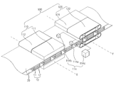
도 1은 본 발명의 제1 실시예에 따른 전극조립체 가열유닛을 도시한 사시도.
도 2는 본 발명의 제1 실시예에 따른 전극조립체 가열유닛을 도시한 평면도.
도 3은 본 발명의 제1 실시예에 따른 전극조립체 가열유닛을 도시한 측면도.
도 4는 도 1에 표시된 'A'방향에서 바라본 전극조립체 가열유닛을 도시한 도면.
도 5는 도 1에 표시된 'B'방향에서 바라본 전극조립체 가열유닛을 도시한 도면.
도 6은 본 발명의 제2 실시예에 따른 라미네이션장치를 도시한 사시도.
도 7은 본 발명의 제2 실시예에 따른 라미네이션방법을 나타낸 순서도.
도 8은 본 발명의 제3 실시예에 따른 전극조립체 가열유닛을 도시한 사시도.
도 9는 본 발명의 제4 실시예에 따른 전극조립체 가열유닛을 도시한 사시도.1 is a perspective view showing an electrode assembly heating unit according to a first embodiment of the present invention.
2 is a plan view showing an electrode assembly heating unit according to a first embodiment of the present invention.
Figure 3 is a side view showing the electrode assembly heating unit according to the first embodiment of the present invention.
4 is a view showing an electrode assembly heating unit viewed from the direction'A' shown in FIG. 1;
5 is a view showing the electrode assembly heating unit viewed from the direction'B' shown in FIG. 1;
6 is a perspective view showing a lamination device according to a second embodiment of the present invention.
7 is a flow chart showing a lamination method according to a second embodiment of the present invention.
8 is a perspective view showing an electrode assembly heating unit according to a third embodiment of the present invention.
9 is a perspective view showing an electrode assembly heating unit according to a fourth embodiment of the present invention.
이하, 첨부한 도면을 참조하여 본 발명이 속하는 기술분야에서 통상의 지식을 가진 자가 용이하게 실시할 수 있도록 본 발명의 실시예를 상세히 설명한다. 그러나 본 발명은 여러 가지 상이한 형태로 구현될 수 있으며 여기에서 설명하는 실시예에 한정되지 않는다. 그리고 도면에서 본 발명을 명확하게 설명하기 위해서 설명과 관계없는 부분은 생략하였으며, 명세서 전체를 통하여 유사한 부분에 대해서는 유사한 도면 부호를 붙였다.Hereinafter, exemplary embodiments of the present invention will be described in detail with reference to the accompanying drawings so that those skilled in the art to which the present invention pertains may easily practice. However, the present invention can be implemented in many different forms and is not limited to the embodiments described herein. In addition, in order to clearly describe the present invention in the drawings, parts irrelevant to the description are omitted, and like reference numerals are assigned to similar parts throughout the specification.
[전극조립체][Electrode assembly]
전극조립체(10)는 전극과 분리막을 포함한다. 즉, 전극조립체(10)는 도 1을 참조하면, 복수의 전극(11)과 복수개의 분리막(12)이 교대로 적층되는 구조를 가진다. The
한편, 상기 복수의 전극(11)은 양극 및 음극일 수 있고, 상기 전극조립체(10)는 양극, 분리막, 음극, 분리막이 순차적으로 적층된 구조를 가질 수 있다.Meanwhile, the plurality of
이와 같은 구조를 가진 전극조립체(10)는 접합력을 높이기 위해 본 발명의 제1 실시예에 따른 전극조립체 가열유닛으로 가열될 수 있다.The
한편, 상기 전극조립체(10)의 양쪽 표면에는 보호필름(20)이 배치되며, 상기 보호필름(20)은 본 발명의 제1 실시예에 따른 전극조립체 가열유닛으로부터 전극조립체(10)를 보호한다.Meanwhile,
그러나 상기 전극조립체(10)는 보호필름(20) 사이에 배치된 상태로 가열 및 이송되는데, 이때 상기 전극조립체는 별도로 고정해 주는 장치가 없는 상태로 이송되기 때문에 상기 보호필름 사이에서 전극조립체가 틀어지거나 또는 전극조립체에 포함된 전극 및 분리막의 정렬이 틀어질 수 있다.However, the
이와 같은 문제점을 해결하기 위해 본 발명의 제1 실시예에 따른 전극조립체 가열유닛은 보호필름(20)이 배치된 전극조립체(10)를 가열함과 동시에 가압한 상태로 이송하는 구조를 가지며, 이에 따라 전극조립체의 고정력을 높일 수 있고, 그 결과 전극조립체(10)가 틀어지거나 또는 전극조립체(10)에 포함된 전극과 분리막의 정렬이 틀어지는 것을 방지할 수 있다.In order to solve this problem, the electrode assembly heating unit according to the first embodiment of the present invention has a structure for heating the
이하, 본 발명에 첨부된 도면을 참조하여 상세히 설명한다.Hereinafter, with reference to the accompanying drawings in the present invention will be described in detail.
[본 발명의 제1 실시예에 따른 전극조립체 가열유닛][The electrode assembly heating unit according to the first embodiment of the present invention]
본 발명의 제1 실시예에 따른 전극조립체 가열유닛(100)은 도 1 내지 도 3에 도시되어 있는 것과 같이, 전극조립체를 가열함과 동시에 이송하는 제1 가열부(101)를 포함한다.The electrode
제1 가열부1st heating part
상기 제1 가열부(110)는 전극조립체(10)를 강제로 가압한 상태로 이송함과 동시에 가열하여 전극조립체(10)에 포함된 전극 및 분리막의 틀어짐을 방지하는 구조를 가진다. The
즉, 상기 제1 가열부(110)는 상기 전극조립체(10)를 1차 가열하는 제1 가열부재(111), 및 상기 제1 가열부재(111)에 의해 가열중인 상기 전극조립체(10)를 강제로 가압한 상태로 이송하는 제1 이송부재(112)를 포함한다.That is, the
상기 제1 가열부재(111)는 전극조립체(10)의 상부와 하부에 각각 배치되도록 한 쌍으로 구비되고, 한 쌍의 상기 제1 가열부재(111)는 상기 전극조립체(10)의 이송방향과 직교되는 제1 라인(X) 상에 배치된다. 이에 따라 상기 제1 가열부재(111)는 상기 제1 라인(X)을 통과하는 전극조립체(10)의 상면과 하면을 향해 열원을 조사하여 전극조립체(10)를 가열하며, 그 결과 전극조립체(10)를 설정된 온도까지 상승시킬 수 있다. 한편, 본 발명에서는 열원을 조사하는 제1 가열부재를 하나의 실시예로 설명하였으나, 적용 설비에 따라 전극조립체(10)의 표면에 직접 열을 전달하여 가열할 수도 있다.The
상기 제1 이송부재(112)는 전극조립체(10) 상면과 하면에 각각 구비되도록 한 쌍으로 구비되고, 한 쌍의 상기 제1 이송부재(112)는 상기 제1 라인(X) 상에 배치된다. 이에 따라 상기 제1 이송부재(112)는 상기 제1 가열부재(111)에 의해 가열중인 상기 전극조립체(10)를 가압한 상태로 이송하게 되고, 특히 상기 제1 이송부재(112)는 보호필름(20)과 전극조립체(10)를 함께 가압한 상태로 이송하여 전극조립체가 틀어지거나 또는 전극조립체(10)에 포함된 전극 및 분리막의 정렬이 틀어지는 것을 방지할 수 있다.The
여기서 상기 제1 이송부재(112)는 상기 전극조립체(10)의 이송방향으로 배치되는 2개의 제1 롤러(112a)와, 상기 2개의 제1 롤러(112a)에 감기고 상기 제1 롤러(112a) 회전시 상기 전극조립체(10)를 가압한 상태로 강제로 이송하는 제1 벨트(112b)를 포함한다. 즉, 상기 제1 이송부재(112)는 제1 롤러(112a)에 의해 순환하는 제1 벨트(112b)에 의해 상기 전극조립체(10)를 가압한 상태로 이송할 수 있으며, 그 결과 전극조립체(10)에 포함된 전극 및 분리막을 틀어지지 않게 안정적으로 이송할 수 있다.Here, the
이와 같은 구성을 가진 제1 가열부(110)는 상기 전극조립체(10)의 이송방향과 직교되는 제1 라인(X) 상에 배치되는 제1 가열부재(111)와 제1 이송부재(112)를 포함하는 것에 특징을 가지며, 이와 같은 특징으로 인해 전극조립체(10)를 안정적으로 가열함과 동시에 이송할 수 있고, 그 결과 전극조립체가 틀어지거나 또는 전극조립체(10)에 포함된 전극 및 분리막의 정렬이 틀어지는 것을 방지할 수 있다.The
한편, 제1 가열부(110)에서 상기 제1 가열부재(111)는 상기 제1 라인(X) 상에 2개 이상 배치되고, 상기 제1 이송부재(112)는 상기 제1 라인(X) 상에 위치한 2개 이상의 상기 제1 가열부재(111)들 사이에 배치될 수 있다. 일례로, 상기 제1 가열부재(111)는 도 1 및 도 4를 참조하면 상기 제1 라인(X) 상에 위치한 전극조립체(10)의 양쪽 단부에 각각 배치되도록 2개로 마련되고, 상기 제1 이송부재(112)는 상기 제1 라인(X) 상에 위치한 2개의 제1 가열부재(111) 사이에 1개가 마련된다. 이에 따라 제1 가열부(110)는 전극조립체(10)를 안정적으로 가열함과 동시에 이송할 수 있다.Meanwhile, two or more
한편, 상기 제1 가열부(110)는 상기 제1 이송부재(111)에 의해 가압된 상태로 이송되는 상기 전극조립체(10)의 표면을 가열하는 제1 보조가열부재(113)를 더 포함할 수 있다.Meanwhile, the
상기 제1 보조가열부재(113)는 제1 이송부재를 통과하는 상기 전극조립체의 표면을 가열하기 위한 것으로, 제1 벨트(112b)의 내부에 구비되고, 전원인가시 열을 발산하는 구조를 가진다. 이에 따라 상기 제1 보조가열부재(113)는 전원인가시 발산하는 열을 이용하여 상기 제1 벨트(112b)에 가압되는 전극조립체(10)의 표면을 가열하며, 이에 따라 제1 라인(X)을 통과하는 전극조립체(10)의 표면 전체를 가열할 수 있다. 한편, 상기 제1 보조가열부재(113)는 2개의 롤러(112a)에 더 내장될 수도 있으며, 이에 따라 2개의 롤러(112a)에 위치하는 전극조립체(10)의 표면을 연속하여 가열할 수 있고, 그 결과 상기 제1 이송부재를 통과한 전극조립체의 안정적으로 가열할 수 있다.The first
한편, 상기 제1 가열부(110)는 상기 제1 가열부재(111)를 통과한 상기 전극조립체(10)의 표면 온도와 상기 제1 이송부재(112)를 통과한 상기 전극조립체(10)의 표면 온도가 일치하도록 제어하는 제어부재(114)를 더 포함할 수 있다. 즉, 상기 제어부재(114)는 제1 가열부재(111)를 통과한 상기 전극조립체(10)의 표면 온도를 측정하는 제1 온도센서(114a), 상기 제1 이송부재(112)를 통과한 상기 전극조립체(10)의 표면 온도를 측정하는 제2 온도센서(114b), 및 상기 제1 온도센서(114a)에 의해 측정된 제1 온도와 제2 온도센서(114b)에 의해 측정된 제2 온도를 대비한 후, 설정된 온도범위 외에 위치하면 상기 제1 가열부재(111)의 온도를 조절하거나 또는 상기 제1 보조가열부재(113)의 온도를 조절하여 상기 제1 온도와 상기 제2 온도를 설정된 온도 범위 내에 위치하도록 조절하는 조절편(114c)을 포함한다. 이에 따라 상기 제어부재(114)는 상기 제1 가열부(110)를 통과하는 전극조립체(10)의 전체를 동일한 온도로 가열할 수 있다.On the other hand, the
제2 가열부Second heating part
한편, 본 발명의 제1 실시예에 따른 전극조립체 가열유닛(100)은 도 1 및 도 5에 도시되어 있는 것과 같이, 제1 가열부(110)를 통과한 전극조립체(10)를 2차로 가열하는 제2 가열부(120)를 더 포함할 수 있다. 즉, 상기 제2 가열부(120)는 상기 제1 가열부(110)를 통과한 상기 전극조립체(10)의 이송방향과 직교되는 제2 라인(Y) 상에 배치되고, 상기 전극조립체(10)를 가열함과 동시에 이송하는 구조를 가진다. 특히 상기 제2 가열부(120)는 전극조립체를 가압한 상태로 이송함과 동시에 상기 제1 이송부재(112)를 통과하는 전극조립체(10)의 표면을 가열하며, 이에 따라 전극조립체(10)의 표면 중 가열되지 않는 부분을 제거할 수 있고, 그 결과 전극조립체(10)의 전체표면을 균일하게 가열할 수 있다.On the other hand, the electrode
즉, 상기 제2 가열부(120)는 상기 제2 라인(Y) 상에 배치되되, 상기 제1 이송부재(112)를 통과한 상기 전극조립체(10)를 가열하는 제2 가열부재(121), 및 상기 제2 라인(Y) 상에 배치되되, 상기 제1 가열부재(111)를 통과한 가열된 상기 전극조립체(10)를 가압한 상태로 이송하는 제2 이송부재(122)를 포함한다.That is, the
이에 따라 상기 제2 가열부(120)는 상기 제1 이송부재(112)를 통과한 상기 전극조립체(10)의 표면은 제2 가열부재(121)로 가열하여 온도를 상승시키고, 상기 제1 가열부재(111)를 통과한 가열된 상기 전극조립체(10)의 표면은 제2 이송부재(122)로 가압하여 이송한다. 그 결과 전극조립체(10) 표면 전체를 가열할 수 있고, 특히 전극조립체(10)의 표면이 연속하여 2번 가열되는 것을 방지하여 전극조립체의 전체온도를 균일하게 조절할 수 있다.Accordingly, the
여기서 상기 제2 가열부재(121)는 앞에서 설명한 제1 가열부재(111)와 동일한 구조를 가진다.Here, the
또한, 상기 제2 이송부재(122)는 앞에서 설명한 제1 이송부재(112)와 동일한 구조를 가진다. 즉, 상기 제2 이송부재(122)는 2개의 제2 롤러(122a)와, 상기 2개의 제2 롤러(122a)에 감기고 2개의 제2 롤러(122a) 회전시 상기 전극조립체(10)를 가압한 상태로 강제로 이송하는 제2 벨트(122b)를 포함한다. 이에 따라 상기 제2 이송부재(122)는 상기 전극조립체(10)를 안정적으로 가압한 상태로 이송할 수 있고, 그 결과 전극조립체(10)에 포함된 전극 및 분리막이 틀어지는 현상을 방지할 수 있다.In addition, the
한편, 상기 제2 가열부(120)는 상기 제2 벨트(122b)에 의해 가압된 상기 전극조립체(10)의 표면을 가열하는 제2 보조가열부재(123)를 더 포함할 수 있다.Meanwhile, the
상기 제2 보조가열부재(123)는 제2 이송부재를 통과하는 상기 전극조립체의 표면을 가열하기 위한 것으로, 제2 벨트(122b)의 내부에 구비되고, 전원인가시 열을 발산하는 구조를 가진다. 이에 따라 상기 제2 보조가열부재(123)는 전원인가시 발산하는 열을 이용하여 상기 제2 벨트(122b)에 가압되는 전극조립체(10)의 표면을 가열하며, 이에 따라 제2 라인(Y)을 통과하는 전극조립체(10)의 표면 전체를 가열할 수 있다. 한편, 상기 제2 보조가열부재(123)는 2개의 롤러(122a)에 더 내장될 수도 있으며, 이에 따라 2개의 롤러(122a)에 위치하는 전극조립체(10)의 표면을 연속하여 가열할 수 있고, 그 결과 상기 제2 이송부재를 통과하는 상기 전극조립체의 표면을 안정적으로 가열할 수 있다.The second
한편, 상기 제1 라인(X) 상에 배치된 제1 가열부재(111) 및 제1 이송부재(112)를 포함한 제1 가열부(110)의 전폭과, 상기 제2 라인(Y) 상에 배치된 제2 가열부재(121) 및 제2 이송부재(122)를 포함한 제2 가열부(120)의 전폭은 동일하게 이루어진다. 특히 상기 제2 가열부재(122)의 전폭은 상기 제1 이송부재(111)의 전폭 보다 크게 형성되고, 상기 제2 이송부재(121)의 전폭은 상기 제1 가열부재(111)의 전폭 보다 작게 형성되며, 이에 따라 상기 제2 가열부재(122)는 제1 이송부재(112)를 통과하는 전극조립체(10)의 표면과 제1 가열부재(111)를 통과하는 전극조립체의 일부 표면을 함께 가열할 수 있고, 그 결과 전극조립체(10)의 표면 중 가열되지 않는 표면이 발생하는 것을 방지할 수 있다.On the other hand, the entire width of the
따라서 본 발명의 제1 실시예에 따른 전극조립체 가열유닛(100)은 제1 가열부(110)와 제2 가열부(120)를 포함하는 것에 특징을 가지며, 이와 같은 특징으로 인해 전극조립체(10)를 안정적으로 가열할 수 있고, 특히 보호필름(20) 사이에 배치된 전극조립체(10)가 틀어지거나 또는 전극조립체(10)에 포함된 전극 및 분리막의 정렬이 틀어지는 현상을 방지할 수 있으며, 그 결과 제품불량을 방지할 수 있다.Therefore, the electrode
이하, 본 발명의 다른 실시예를 설명함에 있어 전술한 실시예와 동일한 기능을 가지는 구성에 대해서는 동일한 구성부호를 사용하며, 중복되는 설명은 생략한다.Hereinafter, in describing another embodiment of the present invention, the same configuration code is used for a configuration having the same function as the above-described embodiment, and overlapping description is omitted.
[본 발명의 제2 실시예에 따른 라미네이션장치][Lamination apparatus according to the second embodiment of the present invention]
본 발명의 제2 실시예에 따른 라미네이션장치는 도 6에 도시되어 있는 것과 같이, 전극조립체(10)를 공급하는 공급유닛(30), 상기 공급유닛(30)에 의해 공급된 상기 전극조립체(10)를 가열함과 동시에 가압한 상태로 이송하는 전극조립체 가열유닛(100), 및 상기 전극조립체 가열유닛(100)에 의해 가열된 상기 전극조립체(10)를 압연하여 접합하는 라미네이션유닛(40)을 포함한다. The lamination apparatus according to the second embodiment of the present invention, as shown in Figure 6, the
여기서 본 발명의 제2 실시예에 따른 라미네이션장치는 전극조립체(10)에 배치된 보호필름(20)을 제거하는 보호필름 제거유닛을 더 포함할 수 있다.Here, the lamination apparatus according to the second embodiment of the present invention may further include a protective film removal unit for removing the
상기 공급유닛(30)은 전극과 분리막이 교대로 적층된 전극조립체(10)를 전극조립체 가열유닛(100)까지 이송한다. 이때 상기 공급유닛(30)은 컨베어벨트를 이용하여 전극조립체(10)를 안정적으로 이송할 수 있다.The
상기 전극조립체 가열유닛(100)은 전극조립체를 가열함과 동시에 이송하는 제1 가열부(110)를 포함하고, 상기 제1 가열부(110)는 상기 전극조립체(10)의 이송방향과 직교되는 제1 라인(X) 상에 배치되고 상기 전극조립체(10)를 1차 가열하는 제1 가열부재(111) 및 상기 제1 라인(X) 상에 배치되고 상기 제1 가열부재(111)에 의해 가열중인 상기 전극조립체(10)를 가압한 상태로 이송하는 제1 이송부재(112)를 포함한다.The electrode
또한, 상기 전극조립체 가열유닛(100)은 상기 제1 가열부(110)를 통과한 상기 전극조립체(10)의 이송방향과 직교되는 제2 라인(Y) 상에 배치되고, 상기 전극조립체를 가열함과 동시에 이송하는 제2 가열부(102)를 더 포함한다.In addition, the electrode
한편, 상기 전극조립체 가열유닛(100)은 앞에서 설명한 제1 실시예에 따른 전극조립체 가열유닛과 동일한 구성과 기능을 가지며, 이에 따라 중복되는 설명은 생략한다.On the other hand, the electrode
상기 라미네이션유닛(40)은 2개의 압연롤러로 형성되고, 2개의 압연롤러는 전극조립체(10)의 양쪽 표면은 압연하여 전극조립체(10)에 포함된 전극과 분리막을 접합한다.The
따라서 본 발명의 제2 실시예에 따른 라미네이션장치는 상기 전극조립체 가열유닛(100)을 포함하는 것에 특징을 가지며, 이와 같은 특징으로 인해 전극과 분리막의 정렬도가 높은 전극조립체를 제조할 수 있다.Therefore, the lamination apparatus according to the second embodiment of the present invention is characterized by including the electrode
이하, 본 발명의 제2 실시예에 따른 라미네이션장치를 이용한 라미네이션방법을 설명한다.Hereinafter, a lamination method using a lamination apparatus according to a second embodiment of the present invention will be described.
[본 발명의 제2 실시예에 따른 라미네이션방법][Lamination method according to the second embodiment of the present invention]
본 발명의 제2 실시예에 따른 라미네이션방법은 도 7에 도시되어 있는 것과 같이, 전극조립체(10)를 공급하는 전극조립체 공급단계(S10), 상기 전극조립체 공급단계(S10)에 의해 공급된 전극조립체(10)를 전극조립체 가열유닛(100)으로 가열함과 동시에 가압한 상태로 이송하는 전극조립체 가열단계(S20), 및 상기 전극조립체 가열단계(S20)에 의해 가열 및 이송된 전극조립체를 압연하여 접합하는 전극조립체 접합단계(S30)를 포함한다.The lamination method according to the second embodiment of the present invention, as shown in Figure 7, the electrode assembly supply step (S10) for supplying the
전극조립체 공급단계Electrode assembly supply step
전극조립체 공급단계(S10)는 공급유닛(30)을 이용하여 전극과 분리막이 교대로 적층된 전극조립체(10)를 이송하여 전극조립체 가열유닛(100)에 공급한다. In the electrode assembly supply step (S10), the
이때 상기 전극조립체(10)의 양쪽 표면에는 보호필름이 배치되고, 상기 보호필름이 배치된 전극조립체(10)가 상기 전극조립체 가열유닛(100)에 공급된다.At this time, protective films are disposed on both surfaces of the
전극조립체 가열단계Electrode assembly heating step
전극조립체 가열단계(S20)는 상기 전극조립체 공급단계(S10)에 의해 공급된 전극조립체(10)를 상기 전극조립체 가열유닛(100)의 제1 가열부(110)로 가열함과 동시에 가압한 상태로 이송하는 제1 가열공정(S21)을 포함한다.In the electrode assembly heating step (S20), the
여기서 상기 제1 가열부(S21)는 상기 전극조립체(10)의 이송방향과 직교되는 제1 라인(X) 상에 배치되면서 상기 전극조립체(10)를 1차 가열하는 제1 가열부재(111)와, 상기 제1 라인(X) 상에 배치되면서 상기 제1 가열부재(111)에 의해 가열중인 상기 전극조립체(10)를 가압한 상태로 이송하는 제1 이송부재(112)를 포함한다.Here, the first heating unit (S21) is disposed on the first line (X) orthogonal to the transfer direction of the
이에 따라 상기 제1 가열공정(S21)은 상기 전극조립체 공급단계(S10)에 의해 공급된 전극조립체(10)를 가열함과 동시에 가압한 상태로 이송하며, 이에 따라 전극조립체를 안정적으로 가열할 수 있고, 특히 보호필름 사이에 배치된 전극조립체(10)의 틀어짐 현상 또는 전극조립체(10)에 포함된 전극과 분리막의 틀어짐 현상을 방지할 수 있다.Accordingly, the first heating process (S21) heats and transfers the
한편, 상기 전극조립체 가열단계(S20)는, 상기 제1 가열공정(S21)을 통과한 전극조립체(10)를 상기 전극조립체 가열유닛(100)의 제2 가열부(120)로 가열함과 동시에 가압한 상태로 이송하는 제2 가열공정(S22)을 더 포함한다.On the other hand, in the electrode assembly heating step (S20), the
여기서 상기 제2 가열부(120)는 상기 제1 가열부(110)를 통과한 상기 전극조립체(10)의 이송방향과 직교되는 제2 라인(Y) 상에 배치되면서 상기 제1 이송부재(112)를 통과하는 상기 전극조립체(10)의 표면을 가열하는 제2 가열부재(121)와, 상기 제2 라인(Y) 상에 배치되면서 상기 제1 가열부재(111)를 통과한 상기 전극조립체(10)를 가압한 상태로 이송하는 제2 이송부재(122)를 포함한다.Here, the
이에 따라 제2 가열공정(S22)은 제1 가열부(110)를 통과한 전극조립체(10)의 표면 중 가열되지 않은 표면을 제2 가열부(120)를 이용하여 가열할 수 있으며, 그 결과 전극조립체(10)의 전체 표면을 가열할 수 있다. 특히 가열중인 전극조립체를 가압한 상태로 이송하여 보호필름(20) 사이에 배치된 전극조립체(10)의 틀어짐 현상 또는 전극조립체(10)에 포함된 전극과 분리막의 틀어짐 현상을 방지할 수 있다.Accordingly, the second heating process (S22) may heat the unheated surface of the surface of the
한편, 상기 전극조립체 가열단계(S20)은 전극조립체의 가열이 완료되면, 상기 전극조립체(10)에 배치된 보호필름을 제거하는 공정을 더 포함할 수 있다.Meanwhile, the electrode assembly heating step (S20) may further include a process of removing the protective film disposed on the
전극조립체 접합단계Electrode assembly bonding step
전극조립체 접합단계(S30)는 라미네이션유닛(40)을 이용하여 가열된 전극조립체(10)를 압연하며, 이에 따라 전극조립체(10)에 포함된 전극과 분리막의 접합력을 높일 수 있다.In the electrode assembly bonding step (S30), the
[본 발명의 제3 실시예에 따른 전극조립체 가열유닛][The electrode assembly heating unit according to the third embodiment of the present invention]
본 발명의 제3 실시예에 따른 전극조립체 가열유닛(100)은 도 8에 도시되어 있는 것과 같이, 전극조립체(10)를 가열함과 동시에 이송하는 제1 가열부(110)를 포함한다.The electrode
상기 제1 가열부(110)는 상기 전극조립체(10)의 이송방향과 직교되는 제1 라인(X) 상에 배치되고 상기 전극조립체(10)를 1차 가열하는 제1 가열부재(111), 및 상기 제1 라인(X) 상에 배치되고 상기 제1 가열부재(111)에 의해 가열중인 상기 전극조립체(10)를 가압한 상태로 이송하는 제1 이송부재(112)를 포함한다.The
여기서 상기 제1 가열부재(111)는 상기 제1 라인(X) 상에 1개가 배치되고, 상기 제1 이송부재(112)는 상기 제1 라인(X) 상에 위치한 1개의 상기 제1 가열부재(111) 양쪽 측부에 각각 배치된다.Here, one of the
그리고 본 발명의 제3 실시예에 따른 전극조립체 가열유닛(100)은 제1 가열부(110)를 통과한 전극조립체(10)를 가열하는 제2 가열부(120)를 더 포함할 수 있다.In addition, the electrode
상기 제2 가열부(120)는 상기 제2 라인(Y) 상에 배치되되 상기 제1 이송부재(112)를 통과한 상기 전극조립체(10)를 가열하는 제2 가열부재(121), 및 상기 제2 라인(Y) 상에 배치되되 상기 제1 가열부재(111)를 통과한 가열된 상기 전극조립체(10)를 가압한 상태로 이송하는 제2 이송부재(122)를 포함한다.The
즉, 본 발명의 제3 실시예에 따른 전극조립체 가열유닛(100)의 제1 가열부(110)와 제2 가열부(120)는 앞에서 설명한 제1 실시예에 따라 전극조립체 가열유닛(100)에 포함된 제1 가열부 및 제2 가열부와 반대로 배치한 구조를 가진다.That is, the
따라서 본 발명의 제3 실시예에 따른 전극조립체 가열유닛(100)은 제1 가열부(110)와 제2 가열부(120)를 새롭게 배치할 수 있으며, 이에 따라 호환성과 사용성을 높일 수 있다.Therefore, in the electrode
[본 발명의 제4 실시예에 따른 전극조립체 가열유닛] [The electrode assembly heating unit according to the fourth embodiment of the present invention]
본 발명의 제4 실시예에 따른 전극조립체 가열유닛(100)은 도 9에 도시되어 있는 것과 같이, 전극조립체(10)를 가열함과 동시에 이송하는 제1 가열부(110)를 포함한다.The electrode
상기 제1 가열부(110)는 상기 전극조립체(10)의 이송방향과 직교되는 제1 라인(X) 상에 배치되고 상기 전극조립체(10)를 1차 가열하는 제1 가열부재(111), 및 상기 제1 라인(X) 상에 배치되고 상기 제1 가열부재(111)에 의해 가열중인 상기 전극조립체(10)를 가압한 상태로 이송하는 제1 이송부재(112)를 포함한다.The
여기서 상기 제1 가열부재(111)는 상기 제1 라인(X)을 통과하는 상기 전극조립체(10)의 일측 단부를 가열하고, 상기 제1 이송부재(112)는 상기 제1 라인(X) 상에 위치한 상기 전극조립체(10)의 타측 단부를 가압한 상태로 이송한다.Here, the
그리고 본 발명의 제4 실시예에 따른 전극조립체 가열유닛(100)은 제1 가열부(110)를 통과한 전극조립체(10)를 가열하는 제2 가열부(120)를 더 포함할 수 있다.In addition, the electrode
상기 제2 가열부(120)는 상기 제2 라인(Y)을 통과하는 상기 전극조립체(10)의 타측 단부를 가열하는 제2 가열부재(121), 및 상기 제2 라인(Y)를 통과하는 상기 전극조립체(10)의 일측 단부를 가압한 상태로 이송하는 제2 이송부재(122)를 포함한다.The
따라서 본 발명의 제4 실시예에 따른 전극조립체 가열유닛(100)은 상기 전극조립체(10)의 일측단부와 타측단부를 가열하거나 또는 가압한 상태로 이송하는 구조로 설정할 수도 있다.Therefore, the electrode
본 발명의 범위는 상기 상세한 설명보다는 후술하는 특허청구범위에 의하여 나타내어지며, 특허청구범위의 의미 및 범위 그리고 그 균등 개념으로부터 도출되는 다양한 실시 형태가 가능하다.The scope of the present invention is indicated by the following claims rather than the above detailed description, and various embodiments derived from the meaning and scope of the claims and their equivalent concepts are possible.
100: 전극조립체 가열유닛
110: 제1 가열부
111: 제1 가열부재
112: 제1 이송부재
120: 제2 가열부
121: 제2 가열부재
122: 제2 이송부재100: electrode assembly heating unit
110: first heating unit
111: first heating member
112: first transfer member
120: second heating unit
121: second heating member
122: second transfer member
Claims (15)
상기 제1 가열부는,
상기 전극조립체의 이송방향과 직교되는 제1 라인 상에 배치되고, 상기 전극조립체를 1차 가열하는 제1 가열부재; 및
상기 제1 라인 상에 배치되고, 상기 제1 가열부재에 의해 가열중인 상기 전극조립체를 가압한 상태로 이송하는 제1 이송부재를 포함하는 전극조립체 가열유닛.It includes a first heating unit for heating and transferring the electrode assembly at the same time,
The first heating unit,
A first heating member disposed on a first line orthogonal to the transfer direction of the electrode assembly and primarily heating the electrode assembly; And
An electrode assembly heating unit including a first transfer member disposed on the first line and transferring the electrode assembly being heated by the first heating member in a pressurized state.
상기 제1 가열부재는, 상기 제1 라인 상에 2개 이상 배치되고,
상기 제1 이송부재는, 상기 제1 라인 상에 위치한 2개 이상의 상기 제1 가열부재들 사이에 배치되는 전극조립체 가열유닛.The method according to claim 1,
Two or more first heating members are disposed on the first line,
The first transfer member is an electrode assembly heating unit disposed between two or more of the first heating members located on the first line.
상기 제1 가열부재는, 상기 제1 라인 상에 1개가 배치되고,
상기 제1 이송부재는, 상기 제1 라인 상에 위치한 1개의 상기 제1 가열부재 양쪽 측부에 각각 배치되는 전극조립체 가열유닛.The method according to claim 1,
One of the first heating members is disposed on the first line,
The first transfer member, the electrode assembly heating unit disposed on both sides of one of the first heating member located on the first line.
상기 제1 이송부재는,
2개의 제1 롤러와,
상기 2개의 제1 롤러에 감기고 상기 제1 롤러 회전시 상기 전극조립체를 가압한 상태로 강제로 이송하는 제1 벨트를 포함하는 전극조립체 가열유닛.The method according to claim 1,
The first transfer member,
Two first rollers,
An electrode assembly heating unit including a first belt wound on the two first rollers and forcibly transferring the electrode assembly in a pressurized state when the first roller rotates.
상기 제1 가열부는, 상기 제1 벨트에 의해 가압되는 상기 전극조립체의 표면을 가열하는 제1 보조가열부재를 더 포함하는 전극조립체 가열유닛.The method according to claim 4,
The first heating unit, the electrode assembly heating unit further comprises a first auxiliary heating member for heating the surface of the electrode assembly is pressed by the first belt.
상기 제1 가열부를 통과한 상기 전극조립체의 이송방향과 직교되는 제2 라인 상에 배치되고, 상기 전극조립체를 가열함과 동시에 이송하는 제2 가열부를 더 포함하는 전극조립체 가열유닛.The method according to claim 1,
The electrode assembly heating unit further includes a second heating unit disposed on a second line orthogonal to a transfer direction of the electrode assembly passing through the first heating unit and simultaneously heating and transferring the electrode assembly.
상기 제2 가열부는,
상기 제2 라인 상에 배치되되, 상기 제1 이송부재를 통과한 상기 전극조립체를 가열하는 제2 가열부재; 및
상기 제2 라인 상에 배치되되, 상기 제1 가열부재를 통과한 가열된 상기 전극조립체를 가압한 상태로 이송하는 제2 이송부재를 포함하는 전극조립체 가열유닛.The method according to claim 6,
The second heating unit,
A second heating member disposed on the second line to heat the electrode assembly passing through the first transfer member; And
It is disposed on the second line, the electrode assembly heating unit including a second transfer member for transferring the heated electrode assembly passing through the first heating member in a pressurized state.
상기 제2 이송부재는,
2개의 제2 롤러와,
상기 2개의 제2 롤러에 감기고 상기 2개의 제2 롤러 회전시 상기 전극조립체를 가압한 상태로 강제로 이송하는 제2 벨트를 포함하는 전극조립체 가열유닛.The method according to claim 7,
The second transfer member,
Two second rollers,
An electrode assembly heating unit including a second belt wound on the two second rollers and forcibly transferring the electrode assembly in a pressurized state when the two second rollers rotate.
상기 제2 가열부는, 상기 제2 벨트에 의해 가압된 상기 전극조립체의 표면을 가열하는 제2 보조가열부재를 더 포함하는 전극조립체 가열유닛.The method according to claim 8,
The second heating unit, the electrode assembly heating unit further comprises a second auxiliary heating member for heating the surface of the electrode assembly pressed by the second belt.
상기 제1 라인 상에 배치된 제1 가열부재 및 제1 이송부재를 포함한 제1 가열부의 전폭과, 상기 제2 라인 상에 배치된 제2 가열부재 및 제2 이송부재를 포함한 제2 가열부의 전폭은 동일하되,
상기 제2 가열부재의 전폭은 상기 제1 이송부재의 전폭 보다 크게 형성되고, 상기 제2 이송부재의 전폭은 상기 제1 가열부재의 전폭 보다 작게 형성되는 전극조립체 가열유닛.The method according to claim 7,
The full width of the first heating unit including the first heating member and the first transfer member disposed on the first line, and the full width of the second heating unit including the second heating member and the second transfer member disposed on the second line. Is the same,
The electrode assembly heating unit is formed so that the entire width of the second heating member is larger than the entire width of the first transport member, and the entire width of the second transport member is smaller than the entire width of the first heating member.
상기 공급유닛에 의해 공급된 상기 전극조립체를 가열함과 동시에 가압한 상태로 이송하는 전극조립체 가열유닛;
상기 전극조립체 가열유닛에 의해 가열된 상기 전극조립체를 압연하여 접합하는 라미네이션유닛을 포함하며,
상기 전극조립체 가열유닛은, 전극조립체를 가열함과 동시에 이송하는 제1 가열부를 포함하고,
상기 제1 가열부는,
상기 전극조립체의 이송방향과 직교되는 제1 라인 상에 배치되고, 상기 전극조립체를 1차 가열하는 제1 가열부재; 및
상기 제1 라인 상에 배치되고, 상기 제1 가열부재에 의해 가열중인 상기 전극조립체를 가압한 상태로 이송하는 제1 이송부재를 포함하는 라미네이션장치.Supply unit for supplying the electrode assembly;
An electrode assembly heating unit for heating the electrode assembly supplied by the supply unit and transferring it in a pressurized state at the same time;
And a lamination unit for rolling and bonding the electrode assembly heated by the electrode assembly heating unit,
The electrode assembly heating unit includes a first heating unit for heating and simultaneously transferring the electrode assembly,
The first heating unit,
A first heating member disposed on a first line orthogonal to the transfer direction of the electrode assembly and primarily heating the electrode assembly; And
A lamination device disposed on the first line and including a first transfer member for transferring the electrode assembly being heated by the first heating member in a pressurized state.
상기 전극조립체 가열유닛은, 상기 제1 가열부를 통과한 상기 전극조립체의 이송방향과 직교되는 제2 라인 상에 배치되고, 상기 전극조립체를 가열함과 동시에 이송하는 제2 가열부를 더 포함하는 라미네이션장치.The method according to claim 11,
The electrode assembly heating unit is disposed on a second line orthogonal to the transfer direction of the electrode assembly passing through the first heating unit, and further comprises a second heating unit for heating and transferring the electrode assembly at the same time. .
상기 전극조립체 공급단계(S10)에 의해 공급된 전극조립체를 전극조립체 가열유닛으로 가열함과 동시에 가압한 상태로 이송하는 전극조립체 가열단계(S20); 및
상기 전극조립체 가열단계(S20)에 의해 가열 및 이송된 전극조립체를 압연하여 접합하는 전극조립체 접합단계(S30)를 포함하는 라미네이션방법.An electrode assembly supply step of supplying the electrode assembly (S10);
An electrode assembly heating step (S20) of heating the electrode assembly supplied by the electrode assembly supply step (S10) with an electrode assembly heating unit and transferring it in a pressurized state; And
Lamination method comprising the electrode assembly bonding step (S30) of rolling and bonding the electrode assembly heated and transferred by the electrode assembly heating step (S20).
상기 전극조립체 가열단계(S20)는, 상기 전극조립체 공급단계(S10)에 의해 공급된 전극조립체를 상기 전극조립체 가열유닛의 제1 가열부로 가열함과 동시에 가압한 상태로 이송하는 제1 가열공정을 포함하고,
상기 제1 가열공정에서 상기 제1 가열부는 상기 전극조립체의 이송방향과 직교되는 제1 라인 상에 배치되면서 상기 전극조립체를 1차 가열하는 제1 가열부재와, 상기 제1 라인 상에 배치되면서 상기 제1 가열부재에 의해 가열중인 상기 전극조립체를 이송하는 제1 이송부재를 포함하는 라미네이션방법.The method according to claim 13,
In the electrode assembly heating step (S20), the electrode assembly supplied by the electrode assembly supplying step (S10) is heated to a first heating unit of the electrode assembly heating unit and simultaneously transferred to a first heating process. Including,
In the first heating process, the first heating unit is disposed on a first line orthogonal to the transfer direction of the electrode assembly, and a first heating member for primary heating of the electrode assembly and the first heating member is disposed on the first line. A lamination method comprising a first transfer member for transferring the electrode assembly being heated by a first heating member.
상기 전극조립체 가열단계(S20)는, 상기 제1 가열공정을 통과한 전극조립체를 상기 전극조립체 가열유닛의 제2 가열부로 가열함과 동시에 가압한 상태로 이송하는 제2 가열공정을 더 포함하고,
상기 제2 가열공정에서 상기 제2 가열부는 상기 제1 가열부를 통과한 상기 전극조립체의 이송방향과 직교되는 제2 라인 상에 배치되면서 상기 제1 이송부재를 통과하는 상기 전극조립체의 표면을 가열하는 제2 가열부재와, 상기 제2 라인 상에 배치되면서 상기 제2 가열부재를 통과한 상기 전극조립체를 가압한 상태로 이송하는 제2 이송부재를 포함하는 라미네이션방법.The method according to claim 14,
The electrode assembly heating step (S20) further includes a second heating process for heating the electrode assembly that has passed through the first heating process to the second heating unit of the electrode assembly heating unit and transferring it under pressure.
In the second heating process, the second heating part is disposed on a second line orthogonal to the transfer direction of the electrode assembly passing through the first heating part to heat the surface of the electrode assembly passing through the first transport member. A lamination method comprising a second heating member and a second conveying member disposed on the second line and transferring the electrode assembly passing through the second heating member in a pressurized state.
Priority Applications (1)
| Application Number | Priority Date | Filing Date | Title |
|---|---|---|---|
| KR1020190011335A KR20200093956A (en) | 2019-01-29 | 2019-01-29 | Heating unit for electrode assembly and lamination apparatus and method including the same |
Applications Claiming Priority (1)
| Application Number | Priority Date | Filing Date | Title |
|---|---|---|---|
| KR1020190011335A KR20200093956A (en) | 2019-01-29 | 2019-01-29 | Heating unit for electrode assembly and lamination apparatus and method including the same |
Publications (1)
| Publication Number | Publication Date |
|---|---|
| KR20200093956A true KR20200093956A (en) | 2020-08-06 |
Family
ID=72040101
Family Applications (1)
| Application Number | Title | Priority Date | Filing Date |
|---|---|---|---|
| KR1020190011335A KR20200093956A (en) | 2019-01-29 | 2019-01-29 | Heating unit for electrode assembly and lamination apparatus and method including the same |
Country Status (1)
| Country | Link |
|---|---|
| KR (1) | KR20200093956A (en) |
Cited By (2)
| Publication number | Priority date | Publication date | Assignee | Title |
|---|---|---|---|---|
| CN115832165A (en) * | 2021-09-18 | 2023-03-21 | 宁德时代新能源科技股份有限公司 | Rolling device and rolling method |
| WO2023121252A1 (en) * | 2021-12-20 | 2023-06-29 | 주식회사 엘지에너지솔루션 | Battery case sealing device and battery case sealing method using same |
Citations (1)
| Publication number | Priority date | Publication date | Assignee | Title |
|---|---|---|---|---|
| KR20120060700A (en) | 2010-12-02 | 2012-06-12 | 주식회사 엘지화학 | Novel Device for Laminating Electrode Assembly and Secondary Battery Manufactured Using the Same |
-
2019
- 2019-01-29 KR KR1020190011335A patent/KR20200093956A/en unknown
Patent Citations (1)
| Publication number | Priority date | Publication date | Assignee | Title |
|---|---|---|---|---|
| KR20120060700A (en) | 2010-12-02 | 2012-06-12 | 주식회사 엘지화학 | Novel Device for Laminating Electrode Assembly and Secondary Battery Manufactured Using the Same |
Cited By (3)
| Publication number | Priority date | Publication date | Assignee | Title |
|---|---|---|---|---|
| CN115832165A (en) * | 2021-09-18 | 2023-03-21 | 宁德时代新能源科技股份有限公司 | Rolling device and rolling method |
| CN115832165B (en) * | 2021-09-18 | 2024-01-30 | 宁德时代新能源科技股份有限公司 | Rolling device and rolling method |
| WO2023121252A1 (en) * | 2021-12-20 | 2023-06-29 | 주식회사 엘지에너지솔루션 | Battery case sealing device and battery case sealing method using same |
Similar Documents
| Publication | Publication Date | Title |
|---|---|---|
| KR102516224B1 (en) | Lamination apparatus and method, producing facility of secondary battery including the same | |
| KR101090076B1 (en) | Film heat fusion apparatus for electrode tab of secondary battery | |
| US20220131175A1 (en) | Lamination apparatus and method for secondary battery | |
| US20220393222A1 (en) | Apparatus and method for manufacturing electrode assembly | |
| KR102442472B1 (en) | Lamination apparatus and method for secondary battery | |
| KR20200093956A (en) | Heating unit for electrode assembly and lamination apparatus and method including the same | |
| KR20180023185A (en) | Laminating device for secondary cell | |
| US20230155101A1 (en) | Method for Manufacturing Secondary Battery and Apparatus for Manufacturing Secondary Battery | |
| JP6481258B2 (en) | Electric device separator bonding method, electric device separator bonding apparatus, and electric device | |
| EP4120410A1 (en) | Unit cell manufacturing device and method | |
| KR102287768B1 (en) | Electrode assembly manufacturing method and rechargeable battery manufacturing method | |
| CN106876771B (en) | Apparatus for winding electrode assembly | |
| KR102253132B1 (en) | Method For Manufacturing Unit Cell of Secondary Cell And The Apparatus And System Using the Same | |
| KR101241928B1 (en) | Apparatus for manufacturing pocketed electrode plate | |
| KR101247605B1 (en) | Apparatus for Transporting Film | |
| KR200493852Y1 (en) | Electrode Lamination Device Comprising Feeding Conveyor | |
| KR20210049297A (en) | Method for Manufacturing Electrode Assembly Comprising Step of Simultaneously Applying Heating and Pressure | |
| KR101759376B1 (en) | System For Manufacturing Patterned Electrode And Method For Manufacturing Patterned Electrode | |
| EP2816631B1 (en) | Battery reinforcement method | |
| US20220013803A1 (en) | Apparatus and method for manufacturing electrode assembly | |
| JPH1167229A (en) | Manufacturing equipment of electrode element for polymer battery | |
| US20230126211A1 (en) | Separator Sheet Adhesion Apparatus | |
| EP4358214A1 (en) | Electrode assembly, manufacturing apparatus for electrode assembly, and manufacturing method for electrode assembly | |
| US20230125899A1 (en) | Electrode Manufacturing Apparatus Including Electrode Alignment Unit and Electrode Assembly Manufacturing Apparatus | |
| KR20210120731A (en) | Lamination apparatus and method for secondary battery |