EP3865865A2 - Röntgenphasenkontrastdetektor - Google Patents
Röntgenphasenkontrastdetektor Download PDFInfo
- Publication number
- EP3865865A2 EP3865865A2 EP21154088.5A EP21154088A EP3865865A2 EP 3865865 A2 EP3865865 A2 EP 3865865A2 EP 21154088 A EP21154088 A EP 21154088A EP 3865865 A2 EP3865865 A2 EP 3865865A2
- Authority
- EP
- European Patent Office
- Prior art keywords
- phase
- sub
- detector
- pixel resolution
- contrast imaging
- Prior art date
- Legal status (The legal status is an assumption and is not a legal conclusion. Google has not performed a legal analysis and makes no representation as to the accuracy of the status listed.)
- Granted
Links
Images



Classifications
-
- A—HUMAN NECESSITIES
- A61—MEDICAL OR VETERINARY SCIENCE; HYGIENE
- A61B—DIAGNOSIS; SURGERY; IDENTIFICATION
- A61B6/00—Apparatus or devices for radiation diagnosis; Apparatus or devices for radiation diagnosis combined with radiation therapy equipment
- A61B6/40—Arrangements for generating radiation specially adapted for radiation diagnosis
-
- A—HUMAN NECESSITIES
- A61—MEDICAL OR VETERINARY SCIENCE; HYGIENE
- A61B—DIAGNOSIS; SURGERY; IDENTIFICATION
- A61B6/00—Apparatus or devices for radiation diagnosis; Apparatus or devices for radiation diagnosis combined with radiation therapy equipment
- A61B6/06—Diaphragms
-
- A—HUMAN NECESSITIES
- A61—MEDICAL OR VETERINARY SCIENCE; HYGIENE
- A61B—DIAGNOSIS; SURGERY; IDENTIFICATION
- A61B6/00—Apparatus or devices for radiation diagnosis; Apparatus or devices for radiation diagnosis combined with radiation therapy equipment
- A61B6/42—Arrangements for detecting radiation specially adapted for radiation diagnosis
-
- A—HUMAN NECESSITIES
- A61—MEDICAL OR VETERINARY SCIENCE; HYGIENE
- A61B—DIAGNOSIS; SURGERY; IDENTIFICATION
- A61B6/00—Apparatus or devices for radiation diagnosis; Apparatus or devices for radiation diagnosis combined with radiation therapy equipment
- A61B6/42—Arrangements for detecting radiation specially adapted for radiation diagnosis
- A61B6/4208—Arrangements for detecting radiation specially adapted for radiation diagnosis characterised by using a particular type of detector
- A61B6/4233—Arrangements for detecting radiation specially adapted for radiation diagnosis characterised by using a particular type of detector using matrix detectors
-
- A—HUMAN NECESSITIES
- A61—MEDICAL OR VETERINARY SCIENCE; HYGIENE
- A61B—DIAGNOSIS; SURGERY; IDENTIFICATION
- A61B6/00—Apparatus or devices for radiation diagnosis; Apparatus or devices for radiation diagnosis combined with radiation therapy equipment
- A61B6/42—Arrangements for detecting radiation specially adapted for radiation diagnosis
- A61B6/4291—Arrangements for detecting radiation specially adapted for radiation diagnosis the detector being combined with a grid or grating
-
- A—HUMAN NECESSITIES
- A61—MEDICAL OR VETERINARY SCIENCE; HYGIENE
- A61B—DIAGNOSIS; SURGERY; IDENTIFICATION
- A61B6/00—Apparatus or devices for radiation diagnosis; Apparatus or devices for radiation diagnosis combined with radiation therapy equipment
- A61B6/44—Constructional features of apparatus for radiation diagnosis
-
- A—HUMAN NECESSITIES
- A61—MEDICAL OR VETERINARY SCIENCE; HYGIENE
- A61B—DIAGNOSIS; SURGERY; IDENTIFICATION
- A61B6/00—Apparatus or devices for radiation diagnosis; Apparatus or devices for radiation diagnosis combined with radiation therapy equipment
- A61B6/48—Diagnostic techniques
- A61B6/484—Diagnostic techniques involving phase contrast X-ray imaging
-
- G—PHYSICS
- G01—MEASURING; TESTING
- G01N—INVESTIGATING OR ANALYSING MATERIALS BY DETERMINING THEIR CHEMICAL OR PHYSICAL PROPERTIES
- G01N23/00—Investigating or analysing materials by the use of wave or particle radiation, e.g. X-rays or neutrons, not covered by groups G01N3/00 – G01N17/00, G01N21/00 or G01N22/00
- G01N23/02—Investigating or analysing materials by the use of wave or particle radiation, e.g. X-rays or neutrons, not covered by groups G01N3/00 – G01N17/00, G01N21/00 or G01N22/00 by transmitting the radiation through the material
- G01N23/04—Investigating or analysing materials by the use of wave or particle radiation, e.g. X-rays or neutrons, not covered by groups G01N3/00 – G01N17/00, G01N21/00 or G01N22/00 by transmitting the radiation through the material and forming images of the material
- G01N23/041—Phase-contrast imaging, e.g. using grating interferometers
-
- G—PHYSICS
- G01—MEASURING; TESTING
- G01T—MEASUREMENT OF NUCLEAR OR X-RADIATION
- G01T1/00—Measuring X-radiation, gamma radiation, corpuscular radiation, or cosmic radiation
- G01T1/16—Measuring radiation intensity
- G01T1/20—Measuring radiation intensity with scintillation detectors
- G01T1/2018—Scintillation-photodiode combinations
- G01T1/20184—Detector read-out circuitry, e.g. for clearing of traps, compensating for traps or compensating for direct hits
-
- G—PHYSICS
- G01—MEASURING; TESTING
- G01T—MEASUREMENT OF NUCLEAR OR X-RADIATION
- G01T1/00—Measuring X-radiation, gamma radiation, corpuscular radiation, or cosmic radiation
- G01T1/16—Measuring radiation intensity
- G01T1/24—Measuring radiation intensity with semiconductor detectors
- G01T1/247—Detector read-out circuitry
-
- G—PHYSICS
- G01—MEASURING; TESTING
- G01N—INVESTIGATING OR ANALYSING MATERIALS BY DETERMINING THEIR CHEMICAL OR PHYSICAL PROPERTIES
- G01N2223/00—Investigating materials by wave or particle radiation
- G01N2223/05—Investigating materials by wave or particle radiation by diffraction, scatter or reflection
- G01N2223/064—Investigating materials by wave or particle radiation by diffraction, scatter or reflection interference of radiation, e.g. Borrmann effect
-
- G—PHYSICS
- G01—MEASURING; TESTING
- G01N—INVESTIGATING OR ANALYSING MATERIALS BY DETERMINING THEIR CHEMICAL OR PHYSICAL PROPERTIES
- G01N2223/00—Investigating materials by wave or particle radiation
- G01N2223/30—Accessories, mechanical or electrical features
- G01N2223/304—Accessories, mechanical or electrical features electric circuits, signal processing
-
- G—PHYSICS
- G01—MEASURING; TESTING
- G01N—INVESTIGATING OR ANALYSING MATERIALS BY DETERMINING THEIR CHEMICAL OR PHYSICAL PROPERTIES
- G01N2223/00—Investigating materials by wave or particle radiation
- G01N2223/40—Imaging
- G01N2223/401—Imaging image processing
-
- G—PHYSICS
- G01—MEASURING; TESTING
- G01N—INVESTIGATING OR ANALYSING MATERIALS BY DETERMINING THEIR CHEMICAL OR PHYSICAL PROPERTIES
- G01N2223/00—Investigating materials by wave or particle radiation
- G01N2223/50—Detectors
-
- G—PHYSICS
- G01—MEASURING; TESTING
- G01T—MEASUREMENT OF NUCLEAR OR X-RADIATION
- G01T1/00—Measuring X-radiation, gamma radiation, corpuscular radiation, or cosmic radiation
- G01T1/16—Measuring radiation intensity
- G01T1/24—Measuring radiation intensity with semiconductor detectors
- G01T1/241—Electrode arrangements, e.g. continuous or parallel strips or the like
Definitions
- the subject matter disclosed herein relates to X-ray imaging and, in particular to phase-contrast imaging techniques.
- Non-invasive imaging technologies allow images of the internal structures or features of a patient to be obtained without performing an invasive procedure on the patient.
- such non-invasive imaging technologies rely on various physical principles (such as the differential transmission of X-rays through a target volume, the reflection of acoustic waves within the volume, the paramagnetic properties of different tissues and materials within the volume, the breakdown of targeted radionuclides within the body, and so forth) to acquire data and to construct images or otherwise represent the observed internal features of the patient.
- X-rays are generated by an X-ray source and pass through an object or patient to reach a radiation detector.
- the X-rays are differentially absorbed as they pass through the object or patient based on the composition of the materials in the beam path.
- This differential X-ray absorption allows an image to be generated using the detected X-rays that provides information about internal structures of the object or patient.
- Such an image which may be considered a conventional X-ray image, is useful for conveying information about materials that strongly absorb X-rays (i.e., high atomic weight or high-Z materials) such as bone, which exhibit high contrast with less absorptive materials.
- phase-contrast imaging which can yield information not available with conventional absorption X-ray imaging.
- phase-contrast imaging a series of gratings or a coherent source used in combination with fewer gratings can be employed to impart phase and interference properties to an X-ray beam.
- the resulting X-ray beam when detected, yields additional information, particularly with respect to low atomic weight structures in the beam path as well as microstructures.
- One consequence of use of the gratings is that a portion of the emitted X-rays may be absorbed by the gratings, which may necessitate higher X-ray doses to obtain suitable images.
- a phase-contrast imaging detector comprises a plurality of pixels.
- Each pixel comprises: a detection material that generates a measurable parameter in response to X-ray photons; and a plurality of sub-pixel resolution readout structures.
- the sub-pixel resolution readout structures are in an alternating pattern corresponding to a phase-contrast interference pattern.
- the phase-contrast imaging detector further comprises readout circuitry configured to read out signals from the plurality of sub-pixel resolution readout structures.
- a phase-contrast imaging system comprises: an X-ray source configured to emit X-rays through an imaging volume during operation and at least one grating position in a path of X-rays through the imaging volume. The X-rays, upon passing though the at least one grating generate a spatial interference pattern.
- the phase-contrast imaging system further comprises a phase-sensitive detector configured to generate signals in response to X-rays emitted by the X-ray source and passing through the at least one grating.
- the phase-sensitive detector comprises a plurality of pixels. Some or all of the pixels each comprise a plurality of sub-pixel resolution readout structures.
- the sub-pixel resolution readout structures are in an alternating pattern corresponding to the phase-contrast interference pattern.
- the phase-contrast imaging system further comprises one or more processing components configured to process the signals generated by the plurality of sub-pixel resolution readout structures to generate clinical images.
- a method for phase-contrast imaging is provided.
- an X-ray source of an imaging system is operated to emit X-rays through an imaging volume.
- the X-rays are received at a phase-sensitive detector after the X-rays pass through at least one grating that imparts a spatial interference pattern to the X-rays.
- the phase-sensitive detector comprises a plurality of pixels. Some or all of the pixels each comprise a plurality of sub-pixel resolution readout structures.
- the sub-pixel resolution readout structures are in an alternating pattern corresponding to the phase-contrast interference pattern.
- Signals generated by the plurality of sub-pixel resolution readout structures are processed to determine an amplitude, an offset, and a phase of the phase-contrast interference pattern.
- a phase image, an absorption image, or a darkfield image are generated using at least one or more of the phase, the amplitude, and the offset.
- X-ray imaging is frequently used by medical practitioners to non-invasively acquire information about structures within the body of a patient.
- Conventional X-ray imaging relies on differential absorption of X-rays by structures of different composition within the body to provide useful data.
- differentially absorbed X-rays may be used to generate images that exhibit good contrast for high atomic weight (i.e., high-Z) materials within the body, but provides limited information about features that do not readily absorb X-rays.
- Phase-contrast imaging is also an X-ray based imaging technique, which often utilizes a series of gratings (e.g., absorption or phase gratings) to impart phase and spatial interference properties to the X-ray beam.
- the detected X-rays can then be used to reconstruct not only a conventional X-ray absorption image, but also a phase image (which has good contrast for low-Z materials, such as tissues) and a darkfield image (which allows sub-pixel microstructures, e.g., lung alveoli, to be detected though not resolved).
- a phase image may be useful in contexts where there are low-Z objects which a clinician wishes to view or detect in an environment that also includes high-Z features.
- phase-contrast imaging typically absorb a substantial portion of the X-rays emitted for imaging. As a result, higher X-ray doses are typically employed for phase-contrast imaging than for conventional absorption imaging.
- certain implementations of the present invention eliminate one of the gratings (i.e., a detector-side grating, denoted as the analyzer grating) typically employed in phase-contrast imaging and employ a detector that integrates the function of this grating into the detector itself. In this manner loss of dose attributable to this grating is avoided. This is particularly important in medical imaging, where the X-rays absorbed by the detector-side grating would already have gone through the patient, thereby creating additional X-ray dose for the patient that does not reach the detector.
- incorporating this functionality into the detector also eliminates the need to take multiple acquisitions using an analyzer grating at different phase steps, as discussed in greater detail herein.
- the X-ray based imaging system 10 may be any suitable X-ray imaging modality, such as a computed tomography (CT) imaging system, a C-arm type imaging system, a tomosynthesis imaging system, a conventional radiography imaging system, a mammography imaging system, a fluoroscopy imaging system, and so forth.
- CT computed tomography
- C-arm type imaging system a C-arm type imaging system
- tomosynthesis imaging system a conventional radiography imaging system
- mammography imaging system a mammography imaging system
- fluoroscopy imaging system a fluoroscopy imaging system
- imaging system 10 includes a source of X-ray radiation 12 and a detector 14.
- the X-ray source 12 may be an X-ray tube or comprise one or more other sources of X-ray radiation suitable for the acquisition of medical or other images.
- the X-rays 16 generated by the source 12 pass into an imaging region in which an object to be imaged (e.g., a part undergoing non-destructive evaluation or testing), a tissue sample to be imaged, a bag or package undergoing security screening, a patient undergoing an imaging protocol, and so forth may be positioned.
- an object to be imaged e.g., a part undergoing non-destructive evaluation or testing
- a tissue sample to be imaged e.g., a bag or package undergoing security screening
- a patient undergoing an imaging protocol e.g., a patient 18 undergoing imaging is positioned within the imaging volume during a procedure.
- the X-rays 16 are collimated to be a fan-shaped (planar) or cone-shaped (volumetric) beam, e.g., a fan-beam or cone-beam, which passes through the imaged volume.
- a portion of the X-ray radiation 20 passes through or around the patient 18 (or other subject of interest) and impacts a detector array, represented generally as the detector 14.
- Detector elements e.g., pixels
- Detector elements of the detector 14 produce electrical signals that represent the intensity of the incident X-rays 20 upon detector elements of detector 14. These signals are acquired and processed, as discussed herein, to reconstruct images of the features within the patient 18.
- a detector 14 as used herein will comprise an array of pixels. Each pixel is associated with some medium with which X-rays interact and with sub-pixel resolution electrodes that measure some property or signal generated in response to the interaction of the X-rays with the medium.
- the electrodes associated with a given pixel are in an interleaved or other discontinuous configuration (i.e.
- the electrodes associated with each pixel may take the form of an interlaced or other discontinuous photodiode electrode structure suitable for reading out signals generated in response to the optical photons.
- the electrodes associated with each pixel may similarly be provided as an interlaced or other non-continuous set of electrodes.
- Such direct-conversion type detectors may be configured to provide certain additional functionality, such as being energy-integrating and/or photon-counting type detectors. In photon-counting contexts, the coincidence detection and/or spectral information may also be acquired using the detector 14.
- gratings 22, 24 are positioned in the path of the X-ray beam.
- the grating 22 may be the only grating provided if the source 12 is sufficiently small and/or is coherent.
- an additional source-side grating may be present near the source 12 to effectively cause a larger and/or incoherent source 12 to be perceived as a multitude of spatially-coherent line sources in a phase-contrast context.
- Such gratings may be present to facilitate phase-contrast imaging.
- an analyzer grating 24 opposite the patient 18 relative to the source 12 i.e., on the detector-side
- the source 12 and detector 14 may be a part of an imager subsystem 30.
- imaging modalities e.g., computed tomography (CT), C-arm angiography, tomosynthesis
- the source 12 and detector 14 of the imager 30 may be moved relative to the patient or imaged object along one or more axes during a scan procedure for which projection data is acquired.
- the imager 30 may move about a first axis of rotation, a second axis of rotation, or a third axis of rotation, or any combination thereof.
- the translation and rotation of the imager 30 may be determined or coordinated in accordance with a specified protocol.
- the imager 30 may be held constant, while the object is repositioned, such as in non-destructive testing applications.
- the movement of the imager 30, if any, may be initiated and/or controlled by one or more linear/rotational subsystems 46.
- the linear/rotational subsystems 46 may include support structures, motors, gears, bearings, and the like, that enable the relative rotational and/or translational movement of the imager 30.
- the linear/rotational subsystems 46 may include a structural apparatus (e.g., a C-arm, rotating gantry, turntable, and so forth) supporting the source 12 and the detector 14 or, alternatively, the object or patient 18.
- a system controller 48 may govern the linear/rotational subsystems 46 that initiate and/or control the movement of the components of the imager 30.
- the system controller 48 may incorporate one or more processing devices that include or communicate with tangible, non-transitory, machine readable media collectively storing instructions executable by the one or more processors to facilitate performance of imaging operations.
- the system controller 48 may also include features that control the timing of the activation of the source 12, for example, to control the acquisition of X-ray data obtained during a particular imaging sequence.
- the system controller 48 may also execute various signal processing and filtration functions, such as for initial adjustment of dynamic ranges, interleaving of digital projection data, and so forth. Therefore, in general, the system controller 48 may be considered to command operation of the imaging system 10 to execute examination protocols.
- system controller 48 is the unit that controls acquisitions, movements, and so forth, using the imager 30.
- system controller 48 acts in conjunction with other control devices (e.g., other control circuitry local to the imagers or remote to the system 10) are also encompassed by the present disclosure.
- the system controller 48 includes signal processing circuitry and various other circuitry that enables the system controller 48 to control the operation of the imager 30 and the linear/rotational subsystems 46.
- the circuitry may include an X-ray controller 50 configured to operate the X-ray source 12.
- Circuitry of the system controller 48 may also include one or more motor controllers 52.
- the motor controllers 52 may control the activation of various components that are responsible for moving the source 12 and the detector 14. In other words, the motor controllers may implement a particular acquisition trajectory or motion for the relative motion of the components of the imager 30.
- the system controller 48 is also illustrated as including one or more data acquisition systems 54.
- the detector 14 may be coupled to the system controller 48, and more particularly to the data acquisition systems 54.
- the data acquisition systems 54 may receive data collected by readout electronics of the detector 14 and in certain embodiments may process the data (e.g., by converting analog to digital signals or to perform other filtering, transformations, or similar operations).
- tangible, non-transitory, machine-readable media and the processors that are configured to perform the instructions stored on this media that are present in the system 10 may be shared between the various components of the system controller 48 or other components of the system 10.
- the X-ray controller 50, the motor controller 52, and the data acquisition systems 54 may share one or more processing components 56 that are each specifically configured to cooperate with one or more memory devices 58 storing instructions that, when executed by the processing components 56, perform image acquisition and reconstruction techniques.
- the processing components 56 and the memory components 58 may coordinate in order to perform various image reconstruction processes.
- the system controller 48 and the various circuitry that it includes, as well as the processing and memory components 56, 58, may be accessed or otherwise controlled by an operator via an operator workstation 60.
- the operator workstation 60 may include any application-specific or general-purpose computer that may include one or more programs (for example one or more imaging programs) capable of enabling operator input for the techniques described herein.
- the operator workstation 60 may include various input devices such as a mouse, a keyboard, a trackball, or any other similar feature that enables the operator to interact with the computer.
- the operator workstation 60 may enable the operator to control various imaging parameters, for example, by adjusting certain instructions stored on the memory devices 58.
- the operator workstation 60 may be communicatively coupled to a printer 62 for printing images, patient data, and the like.
- the operator workstation 60 may also be in communication with a display 64 that enables the operator to view various parameters in real time, to view images produced by the acquired data, and the like.
- the operator workstation 60 may also, in certain embodiments, be communicatively coupled to a picture archiving and communication system (PACS) 66.
- PACS picture archiving and communication system
- Such a system may enable the storage of patient data, patient images, image acquisition parameters, and the like. This stored information may be shared throughout the imaging facility and may also be shared with other facilities, for example, a remote client 68.
- the remote client 68 may include hospitals, doctors' offices, or any other similar client.
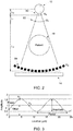
- FIG. 2 depicts features of a conventional phase-contrast imaging technique.
- phase-contrast imaging techniques typically determine a phase-shift angle for each voxel by comparing a spatial interference pattern observed with an object in the beam path with the spatial interference pattern when the object is absent.
- CT phase-contrast computed tomography
- gratings typically three gratings may be employed to generate the interference patterns.
- a source-side grating G 0 (denoted by reference number 80) is positioned near X-ray source 12 to ensure spatial coherence and effectively creates an array of individually coherent, but mutually incoherent emissions in response to operation of an incoherent X-ray source.
- a phase object in the beam path causes a slight refraction for each coherent subset of X-rays.
- the angular deviation so introduced results in changes of the locally transmitted intensity through the pair of gratings G 1 and G 2 (denoted by reference numbers 82 and 84 respectively), which can be detected by an X-ray detector 14 (as shown in FIG. 1 ).
- grating G 1 82 in such an arrangement is located between the source 12 and detector 14 and imprints a periodic interference pattern onto the wave front.
- the grating G 2 84 is located proximate to the detector (i.e., G 2 is a detector-side grating) and resolves sub-pixel resolution interference pattern modulations.
- the gratings may be manufactured from silicon wafers using photolithography and electroplating where appropriate. It may be desirable for the G 1 grating 82 to be close to the source 12 so as to obtain the best sensitivity possible (which is a function of distance L 2 shown in FIG. 2 ).
- the interference pattern created in phase-contrast imaging has three parameters that may be measured (period being known by design): (1) offset; (2) phase; and (3) amplitude. Offset as used herein results from the overall attenuation, as in conventional X-ray imaging.
- Phase is the spatial shift of the interference pattern relative to a reference, which corresponds to a gradient of the real part of the aggregate refractive index seen by an X-ray passing through an object under test.
- Amplitude of the interference pattern is the difference between the peaks and the valleys of the pattern, which may be reduced in the presence of microstructure.
- the present invention eliminates the detector-side grating G 2 84 and integrates the functionality of this grating into a phase-sensitive detector 14A, as shown in FIG. 4 .
- this technique has the further benefit of eliminating the need to take multiple acquisitions at different phase steps, as is typical in a phase-contrast imaging protocol.
- a conventional phase-contrast imaging acquisition when an analyzer grating G 2 84 is used in front of a standard CT detector, only a single measurement can be taken for each pixel at each time.
- the analyzer grating G 2 84 with apertures at a periodicity equaling the frequency of the interference pattern, is typically shifted, and additional (e.g., 3 total measurements) subsequent measurements are taken.
- additional (e.g., 3 total measurements) subsequent measurements are taken.
- a phase-sensitive detector 14A e.g., a detector in which multiple pixel electrodes provide sub-pixel resolutions corresponding to the period of the interference pattern, as discussed in greater detail below
- all 3 independent measurements can be taken simultaneously.
- FIGS. 5 , 6 , and 7 depict examples of a detector module 90 that may be used to form a detector 14A and of pixels 92 provided in the detector module 90.
- the detector module 90 comprises a plurality of pixels 92 formed using silicon, cadmium zinc telluride (CZT), cadmium telluride (CdTe), or other suitable detector materials that generate signal in response to X-rays without a scintillator intermediary component, i.e., direct-conversion detector materials.
- a scintillator may be present as part of the detector 14, as discussed in greater detail with respect to FIGS. 8 and 9 .
- the pixels 92 may increase in length in the direction of the X-ray beam path 20 so as to allow similar response at different depths within the detector. Alternatively, a single, long pixel may be provided that aligns with the direction of the X-ray beam.
- Readout circuitry 96 is depicted as being provided on the side or bottom of the detector module 90 so that detector modules 90 can be combined side-to-side or end-to-end to provide a large or configurable field-of-view.
- FIG. 5 depicts a detection or conversion material 94 (such as a semiconductor material) associated with the pixel 92 with which X-rays interact.
- a detection or conversion material 94 such as a semiconductor material
- FIGS. 6 and 7 depict that within a respective pixel 92, multiple, non-continuous electrodes 98A, 98B, and 98C are associated with the conversion material 94 of each respective pixel 92 to provide sub-pixel resolution measurements.
- the electrodes of FIGS. 6 and 7 are provided as interlaced comb patterns, which may in one embodiment have sub-pixel resolution distances and separations corresponding to the frequency of the spatial interference pattern for a given phase-contrast imaging system.
- the electrodes 98A and 98B form a pattern of alternating arms comprising two interleaved combs.
- the electrodes 98A, 98B, and 98C form a pattern of alternating arms comprising three interleaved combs, one of which is spanned by a conductive bridge 100 provided outside the plane of the other conductive traces so as to allow separate electrical connection to each electrode.
- a conductive bridge 100 provided outside the plane of the other conductive traces so as to allow separate electrical connection to each electrode.
- the interlaced patterns of the electrodes 98 may have a spacing corresponding to the period of the phase-contrast interference pattern, thus allowing all three parameters of interest (i.e., offset, phase, and amplitude) to be measured simultaneously, as opposed to requiring multiple, discrete measurements in which an analyzer grating is shifted, requiring added acquisition time and patient dose.
- a pattern of two and three interleaved sub-pixel resolution electrodes are shown in FIGS. 6 and 7 , respectively, alternate configurations using additional interleaved sub-pixel resolution electrodes as needed to accurately estimate the phase-contrast signals are contemplated.
- the direction in which the electrodes 98 (or other patterned features, such as photodiodes) run may vary depending on the embodiment and may be either in the direction of the X-ray beam 20 (as shown) or orthogonal to the X-ray beam 20.
- the lines of the combs 98 form a line pattern in the direction of the X-ray beam 20, as shown in FIGS. 6 and 7 .
- any pattern may be employed, including a coded aperture, that has spacing corresponding to the phase-contrast interference pattern, as noted above.
- FIG. 8 another embodiment is illustrated which relates to a photodiode-based phase-contrast detector.
- a side-view (above) and a top-view (below) are illustrated together to better depict the various features.
- a single detector pixel 92 is illustrated, with the side-view illustrating the stack of components associated with the detector pixel 92 and the top-view illustrating only the sub-pixel photodiode arrangement with associated separate readout pathways ( a 1 , a 2 , a 3 ) corresponding to the different phases 1, 2, and 3 of the spatial interference pattern.
- the top-view shown in FIG. 8 depicts a high-resolution scintillator 106 in optical communication with multiple sub-pixel photodiodes 110 via an optical coupling layer 108, which may be absent in certain embodiments.
- the scintillator 106 may be formed from a high-Z material and may be arranged in columns or other structures corresponding to pixels 92 (i.e., the scintillator106 may be pixelated) or may be monolithic with respect to the detector surface.
- X-ray photons 20 interact with the scintillator 106 to generate lower-energy photons (e.g., optical photons) that can be detected by the sub-pixel photodiodes 110.
- sub-pixel photodiodes 110 are grouped into an alternating, separated pattern to form three interleaved photodiodes 110A, 110B, and 110C have a separation distance corresponding to the frequency of the spatial interference pattern for the phase-contrast imaging system.
- the pixel 92 is read out using the three separate, interleaved sub-pixel photodiodes 110A, 100B, and 110C such that the readout channel associated with the pixel 92 is comprised of multiple sub-pixels.
- the sub-pixel photodiodes 110 range in width from a few ⁇ m (e.g., 2-5 ⁇ m) to several tens of ⁇ m (e.g., 30-80 ⁇ m).
- the sub-pixel photodiodes 110 may be manufactured as complementary metal-oxide semiconductor (CMOS) devices, lateral metal semiconductor metal (MSM) devices, and so forth.
- CMOS complementary metal-oxide semiconductor
- MSM lateral metal semiconductor metal
- signals for corresponding (i.e., same phase) sub-pixel photodiodes 110 are combined to form the "phase" comb in either the pre-readout (i.e., the analog) domain or the post-readout (i.e., digital) domain.
- a patterned pixel having a pattern of three interleaved combs 98A, 98B, 98C as seen in FIG. 7 is illustrated in conjunction with an X-ray photon 104 that interacts with the detection material (e.g., direct-conversion material or, alternatively, scintillator material) to generate measured signals a 1 , a 2 , and a 3 that may be read out for the pixel 92.
- the detection material e.g., direct-conversion material or, alternatively, scintillator material
- the detection material e.g., direct-conversion material or, alternatively, scintillator material
- a charge cloud is created that spreads out while traveling through the detection material or intermediary substrate to generate a signal that is measured or detected by one or more of the sub-pixel resolution electrodes 98 (or, alternatively, photodiodes 110).
- the total energy deposited during the event i.e., by a given X-ray photon interaction
- measurements at different electrodes 98 may be determined to be coincident in time and therefore attributed to the same X-ray photon.
- the center of the charge cloud i.e., position in the interference pattern
- the size of the charge cloud (which may depend on the depth within the detection material at which the photon is absorbed, as well as on the photon energy) can be determined with greater accuracy.
- the measurements a 1 , a 2 , and a 3 associated with the different respective electrodes 98 (or photodiodes 110) detecting an X-ray photon event can be used to determine the three parameters of interest for a single X-ray photon.
- the significance of such logic in part pertains, as may be ascertained from the preceding discussion, to being able to assign or otherwise associate all of the detected charge for an X-ray photon event (which may be spread across multiple sub-pixel resolution electrodes 98 or photodiodes 110) to a single or primary sub-pixel resolution electrode 98 or photodiode 110.
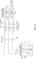
- FIG. 10 one example of coincidence detection in the context of multiple sub-pixel resolution electrodes 98 (or photodiodes in an alternative context) is shown.
- an X-ray photon interacting with the detection material of a respective pixel 92 of a detector 14 causes an initial charge cloud 120 to be generated.
- a voltage applied between the top electrodes 98 and bottom electrode(s) (not shown) causes the charge cloud 120 to move and spread (denoted by reference number 122) toward the top electrodes (i.e., sub-pixel resolution electrodes 98), resulting in measurable signal ( a 1 , a 2 , a 3 ) being generated at multiple electrodes 98.
- the signal (e.g., induced charge) at each electrode 98 is collected and processed by a respective charge sensitive amplifier (CSA) and shaper 126 per channel.
- the signal for each channel is passed to an ADC circuit 128 that is triggered by a comparator output based upon a threshold voltage, V th , where V th is set close to, but above the noise floor (e.g., 5 keV to 10 keV).
- Each detected event generates a time stamp t and a digital output d for each relevant electrode (or photodiode).
- Time stamps t are passed to coincidence logic 140, which determines if a charge has been shared between electrodes 98 based on temporal proximity of the respective time stamps t. Based upon a determination that charge from an X-ray photon event was shared between electrodes 98, "winner-takes-all" logic may be activated and the correct (i.e., incident) counter is incremented for the electrode (or photodiode) determined to correspond to the location of the X-ray photon event (such as based on the largest measured signal).
- the "winner-takes-all" logic may also require that the total energy measured for an X-ray event is greater than an energy threshold in order to increment the appropriate counter.
- a further "winner-takes-all" aggregation step may occur to account for potential charge sharing between pixels 92 (such as due to an X-ray photon being incident near the edges of two or more pixels 92).
- phase-contrast imaging detector having a detector that includes patterned pixel surfaces (e.g., interlaced or interleaved photodiodes or electrodes).
- a system using such a detector may employ only two gratings instead of three gratings to perform phase-contrast imaging, with the functionality of the third grating being performed by the discontinuous pattern of the pixel electrode or photodiode.
- Measurements acquired using the detector may be used to determine offset, amplitude, and phase of a phase-contrast interference pattern without multiple acquisitions at different phase steps of an analyzer grating.
Landscapes
- Health & Medical Sciences (AREA)
- Life Sciences & Earth Sciences (AREA)
- Medical Informatics (AREA)
- Engineering & Computer Science (AREA)
- Physics & Mathematics (AREA)
- Molecular Biology (AREA)
- High Energy & Nuclear Physics (AREA)
- Radiology & Medical Imaging (AREA)
- General Health & Medical Sciences (AREA)
- Nuclear Medicine, Radiotherapy & Molecular Imaging (AREA)
- Pathology (AREA)
- Animal Behavior & Ethology (AREA)
- Veterinary Medicine (AREA)
- Heart & Thoracic Surgery (AREA)
- Biomedical Technology (AREA)
- Surgery (AREA)
- Optics & Photonics (AREA)
- Biophysics (AREA)
- Public Health (AREA)
- General Physics & Mathematics (AREA)
- Spectroscopy & Molecular Physics (AREA)
- Mathematical Physics (AREA)
- Chemical & Material Sciences (AREA)
- Analytical Chemistry (AREA)
- Biochemistry (AREA)
- Immunology (AREA)
- Apparatus For Radiation Diagnosis (AREA)
- Measurement Of Radiation (AREA)
- Solid State Image Pick-Up Elements (AREA)
Applications Claiming Priority (1)
| Application Number | Priority Date | Filing Date | Title |
|---|---|---|---|
| US16/789,100 US11389124B2 (en) | 2020-02-12 | 2020-02-12 | X-ray phase contrast detector |
Publications (3)
| Publication Number | Publication Date |
|---|---|
| EP3865865A2 true EP3865865A2 (de) | 2021-08-18 |
| EP3865865A3 EP3865865A3 (de) | 2021-10-27 |
| EP3865865B1 EP3865865B1 (de) | 2023-08-16 |
Family
ID=74347020
Family Applications (1)
| Application Number | Title | Priority Date | Filing Date |
|---|---|---|---|
| EP21154088.5A Active EP3865865B1 (de) | 2020-02-12 | 2021-01-28 | Röntgenphasenkontrastdetektor |
Country Status (4)
| Country | Link |
|---|---|
| US (1) | US11389124B2 (de) |
| EP (1) | EP3865865B1 (de) |
| JP (1) | JP7167201B2 (de) |
| CN (1) | CN113243927B (de) |
Families Citing this family (6)
| Publication number | Priority date | Publication date | Assignee | Title |
|---|---|---|---|---|
| US11222435B2 (en) * | 2019-11-11 | 2022-01-11 | James R. Glidewell Dental Ceramics, Inc. | Determining rotation axis from x-ray radiographs |
| US12086963B2 (en) * | 2022-02-22 | 2024-09-10 | GE Precision Healthcare LLC | System and method for dynamic phase correction for x-ray phase-contrast imaging |
| US11860319B2 (en) | 2022-03-10 | 2024-01-02 | GE Precision Healthcare LLC | High-resolution detector having a reduced number of pixels |
| US20250107762A1 (en) | 2023-09-29 | 2025-04-03 | GE Precision Healthcare LLC | Device and Method for Integrated Tissue Sample Imaging on Radiography Imaging System |
| US20250311986A1 (en) * | 2024-04-04 | 2025-10-09 | GE Precision Healthcare LLC | Methods and systems for reduced internal scatter crosstalk |
| WO2026053942A1 (ja) * | 2024-09-05 | 2026-03-12 | キヤノン株式会社 | 放射線撮像装置、及び放射線撮像システム |
Family Cites Families (28)
| Publication number | Priority date | Publication date | Assignee | Title |
|---|---|---|---|---|
| US4303860A (en) * | 1979-07-30 | 1981-12-01 | American Science And Engineering, Inc. | High resolution radiation detector |
| US4937453A (en) * | 1987-05-06 | 1990-06-26 | Nelson Robert S | X-ray detector for radiographic imaging |
| US5117114A (en) | 1989-12-11 | 1992-05-26 | The Regents Of The University Of California | High resolution amorphous silicon radiation detectors |
| US5821541A (en) | 1996-02-02 | 1998-10-13 | Tuemer; Tuemay O. | Method and apparatus for radiation detection |
| US7399972B2 (en) * | 2005-06-09 | 2008-07-15 | Nihon Kessho Kogaku Co., Ltd. | Component for radiation detector and radiation detector |
| EP2073040A2 (de) * | 2007-10-31 | 2009-06-24 | FUJIFILM Corporation | Strahlungsabbildungsdetektor und Bildgebungsvorrichtung für die Phasenkontraststrahlung |
| JP5461438B2 (ja) | 2008-02-14 | 2014-04-02 | コーニンクレッカ フィリップス エヌ ヴェ | 位相コントラストイメージング用のx線検出器 |
| US8017906B2 (en) * | 2008-04-08 | 2011-09-13 | Robert Sigurd Nelson | Slit and slot scan, SAR, and compton devices and systems for radiation imaging |
| US8378310B2 (en) | 2009-02-11 | 2013-02-19 | Prismatic Sensors Ab | Image quality in photon counting-mode detector systems |
| JP2010236986A (ja) * | 2009-03-31 | 2010-10-21 | Fujifilm Corp | 放射線位相画像撮影装置 |
| WO2010119019A1 (de) | 2009-04-17 | 2010-10-21 | Siemens Aktiengesellschaft | Detektoranordnung und röntgentomographiegerät zur durchführung von phasenkontrastmessungen sowie verfahren zur durchführung einer phasenkontrastmessung |
| EP2422218A4 (de) * | 2009-04-20 | 2013-12-18 | Integrated Sensors Llp | Detektor für ionisierende partikelstrahlung auf plasmatafelbasis |
| EP2633813B1 (de) * | 2010-10-29 | 2015-02-25 | FUJIFILM Corporation | Phasenkontrast-strahlungsabbildungsvorrichtung |
| US9347893B2 (en) * | 2011-07-26 | 2016-05-24 | Robert Sigurd Nelson | Enhanced resolution imaging systems for digital radiography |
| DE102011082878A1 (de) | 2011-09-16 | 2013-03-21 | Siemens Aktiengesellschaft | Röntgendetektor einer gitterbasierten Phasenkontrast-Röntgenvorrichtung und Verfahren zum Betreiben einer gitterbasierten Phasenkontrast-Röntgenvorrichtung |
| DE102012224258A1 (de) | 2012-12-21 | 2014-06-26 | Siemens Aktiengesellschaft | Röntgenaufnahmesystem zur differentiellen Phasenkontrast-Bildgebung eines Untersuchungsobjekts mit Phase-Stepping sowie angiographisches Untersuchungsverfahren |
| EP2978377B1 (de) * | 2013-03-26 | 2021-05-05 | Institute of Experimental and Applied Physics | Verfahren zur phasengradientenradiografie und anordnung eines abbildungssystems zur anwendung des verfahrens |
| DE102013205406A1 (de) * | 2013-03-27 | 2014-10-16 | Siemens Aktiengesellschaft | Röntgenaufnahmesystem zur Röntgenbildgebung bei hohen Bildfrequenzen eines Untersuchungsobjekts mittels direkter Messung des Interferenzmusters |
| TWI562343B (en) | 2014-05-12 | 2016-12-11 | Ind Tech Res Inst | Electrical radiography imaging system and method thereof |
| EP3271747B1 (de) * | 2015-03-17 | 2022-05-25 | Cornell University | Tiefenfeldbildgebungsvorrichtung, verfahren und anwendungen |
| WO2017015381A1 (en) * | 2015-07-20 | 2017-01-26 | Rensselaer Polytechnic Institute | X-ray phase-contrast and dark-field information extraction with electric fringe scanning and/or active pixel processing |
| CN107850680B (zh) * | 2015-07-21 | 2021-09-21 | 皇家飞利浦有限公司 | 用于相位对比和/或暗场成像的x射线探测器 |
| WO2017212000A1 (en) | 2016-06-08 | 2017-12-14 | Koninklijke Philips N.V. | Analyzing grid for phase contrast imaging and/or dark-field imaging |
| CN109982640A (zh) * | 2016-11-16 | 2019-07-05 | 皇家飞利浦有限公司 | 用于根据相衬成像数据生成多能量数据的装置 |
| US10162066B2 (en) * | 2017-02-06 | 2018-12-25 | General Electric Company | Coincidence-enabling photon-counting detector |
| US10631815B2 (en) | 2017-05-10 | 2020-04-28 | General Electric Company | Scatter correction technique for use with a radiation detector |
| EP3447538A1 (de) * | 2017-08-23 | 2019-02-27 | Koninklijke Philips N.V. | Röntgenstrahldetektion |
| JP6962206B2 (ja) * | 2018-01-15 | 2021-11-05 | 株式会社島津製作所 | X線透視装置 |
-
2020
- 2020-02-12 US US16/789,100 patent/US11389124B2/en active Active
-
2021
- 2021-01-08 CN CN202110024957.XA patent/CN113243927B/zh active Active
- 2021-01-28 EP EP21154088.5A patent/EP3865865B1/de active Active
- 2021-01-29 JP JP2021013763A patent/JP7167201B2/ja active Active
Also Published As
| Publication number | Publication date |
|---|---|
| JP7167201B2 (ja) | 2022-11-08 |
| CN113243927B (zh) | 2024-12-17 |
| EP3865865A3 (de) | 2021-10-27 |
| US11389124B2 (en) | 2022-07-19 |
| CN113243927A (zh) | 2021-08-13 |
| EP3865865B1 (de) | 2023-08-16 |
| US20210244373A1 (en) | 2021-08-12 |
| JP2021128153A (ja) | 2021-09-02 |
Similar Documents
| Publication | Publication Date | Title |
|---|---|---|
| EP3865865B1 (de) | Röntgenphasenkontrastdetektor | |
| CN104394770B (zh) | 基于光栅的差分相位对比成像 | |
| US8576983B2 (en) | X-ray detector for phase contrast imaging | |
| CN110520760B (zh) | 用于辐射检测器的像素设计 | |
| US7646843B2 (en) | Method for producing projective and tomographic phase contrast images with the aid of an X-ray system | |
| US9459358B2 (en) | Reference calibration in photon counting based spectral CT | |
| EP2370836B1 (de) | Spektrale bildgebung | |
| US20170090039A1 (en) | Layered radiation detector | |
| US20180140269A1 (en) | X-ray imaging | |
| WO2014055066A1 (en) | Detector array comprising energy integrating and photon counting cells | |
| US9482630B2 (en) | Multiple-layered energy-integrating detector in a hybrid computed tomography scanner | |
| JP2012200567A (ja) | 放射線撮影システム及び放射線撮影方法 | |
| JP7341721B2 (ja) | 放射線検出器、及びx線ct装置 | |
| EP3541285B1 (de) | Vorrichtung zur erzeugung von mehrfachenergiedaten aus phasenkontrastbildgebungsdaten | |
| US12248108B2 (en) | High-resolution detector having a reduced number of pixels | |
| WO2012169426A1 (ja) | 放射線撮影システム | |
| US12086963B2 (en) | System and method for dynamic phase correction for x-ray phase-contrast imaging | |
| EP3723612B1 (de) | Einzelschussbild-röntgenstrahl-phasenkontrast- und dunkelfeldbildgebung | |
| JP2014155509A (ja) | 放射線撮影システム | |
| JP2012228369A (ja) | 放射線撮影システム及び放射線撮影方法 |
Legal Events
| Date | Code | Title | Description |
|---|---|---|---|
| PUAI | Public reference made under article 153(3) epc to a published international application that has entered the european phase |
Free format text: ORIGINAL CODE: 0009012 |
|
| STAA | Information on the status of an ep patent application or granted ep patent |
Free format text: STATUS: REQUEST FOR EXAMINATION WAS MADE |
|
| 17P | Request for examination filed |
Effective date: 20210128 |
|
| AK | Designated contracting states |
Kind code of ref document: A2 Designated state(s): AL AT BE BG CH CY CZ DE DK EE ES FI FR GB GR HR HU IE IS IT LI LT LU LV MC MK MT NL NO PL PT RO RS SE SI SK SM TR |
|
| PUAL | Search report despatched |
Free format text: ORIGINAL CODE: 0009013 |
|
| AK | Designated contracting states |
Kind code of ref document: A3 Designated state(s): AL AT BE BG CH CY CZ DE DK EE ES FI FR GB GR HR HU IE IS IT LI LT LU LV MC MK MT NL NO PL PT RO RS SE SI SK SM TR |
|
| RIC1 | Information provided on ipc code assigned before grant |
Ipc: G01T 1/24 20060101ALI20210921BHEP Ipc: G01T 1/20 20060101ALI20210921BHEP Ipc: A61B 6/00 20060101ALI20210921BHEP Ipc: G01N 23/041 20180101AFI20210921BHEP |
|
| GRAP | Despatch of communication of intention to grant a patent |
Free format text: ORIGINAL CODE: EPIDOSNIGR1 |
|
| STAA | Information on the status of an ep patent application or granted ep patent |
Free format text: STATUS: GRANT OF PATENT IS INTENDED |
|
| INTG | Intention to grant announced |
Effective date: 20230302 |
|
| RAP3 | Party data changed (applicant data changed or rights of an application transferred) |
Owner name: GENERAL ELECTRIC COMPANY |
|
| GRAS | Grant fee paid |
Free format text: ORIGINAL CODE: EPIDOSNIGR3 |
|
| P01 | Opt-out of the competence of the unified patent court (upc) registered |
Effective date: 20230528 |
|
| GRAA | (expected) grant |
Free format text: ORIGINAL CODE: 0009210 |
|
| STAA | Information on the status of an ep patent application or granted ep patent |
Free format text: STATUS: THE PATENT HAS BEEN GRANTED |
|
| AK | Designated contracting states |
Kind code of ref document: B1 Designated state(s): AL AT BE BG CH CY CZ DE DK EE ES FI FR GB GR HR HU IE IS IT LI LT LU LV MC MK MT NL NO PL PT RO RS SE SI SK SM TR |
|
| REG | Reference to a national code |
Ref country code: CH Ref legal event code: EP Ref country code: DE Ref legal event code: R096 Ref document number: 602021004210 Country of ref document: DE |
|
| REG | Reference to a national code |
Ref country code: IE Ref legal event code: FG4D |
|
| REG | Reference to a national code |
Ref country code: LT Ref legal event code: MG9D |
|
| REG | Reference to a national code |
Ref country code: NL Ref legal event code: MP Effective date: 20230816 |
|
| REG | Reference to a national code |
Ref country code: AT Ref legal event code: MK05 Ref document number: 1600514 Country of ref document: AT Kind code of ref document: T Effective date: 20230816 |
|
| PG25 | Lapsed in a contracting state [announced via postgrant information from national office to epo] |
Ref country code: GR Free format text: LAPSE BECAUSE OF FAILURE TO SUBMIT A TRANSLATION OF THE DESCRIPTION OR TO PAY THE FEE WITHIN THE PRESCRIBED TIME-LIMIT Effective date: 20231117 |
|
| PG25 | Lapsed in a contracting state [announced via postgrant information from national office to epo] |
Ref country code: IS Free format text: LAPSE BECAUSE OF FAILURE TO SUBMIT A TRANSLATION OF THE DESCRIPTION OR TO PAY THE FEE WITHIN THE PRESCRIBED TIME-LIMIT Effective date: 20231216 |
|
| PG25 | Lapsed in a contracting state [announced via postgrant information from national office to epo] |
Ref country code: SE Free format text: LAPSE BECAUSE OF FAILURE TO SUBMIT A TRANSLATION OF THE DESCRIPTION OR TO PAY THE FEE WITHIN THE PRESCRIBED TIME-LIMIT Effective date: 20230816 Ref country code: RS Free format text: LAPSE BECAUSE OF FAILURE TO SUBMIT A TRANSLATION OF THE DESCRIPTION OR TO PAY THE FEE WITHIN THE PRESCRIBED TIME-LIMIT Effective date: 20230816 Ref country code: PT Free format text: LAPSE BECAUSE OF FAILURE TO SUBMIT A TRANSLATION OF THE DESCRIPTION OR TO PAY THE FEE WITHIN THE PRESCRIBED TIME-LIMIT Effective date: 20231218 Ref country code: NO Free format text: LAPSE BECAUSE OF FAILURE TO SUBMIT A TRANSLATION OF THE DESCRIPTION OR TO PAY THE FEE WITHIN THE PRESCRIBED TIME-LIMIT Effective date: 20231116 Ref country code: NL Free format text: LAPSE BECAUSE OF FAILURE TO SUBMIT A TRANSLATION OF THE DESCRIPTION OR TO PAY THE FEE WITHIN THE PRESCRIBED TIME-LIMIT Effective date: 20230816 Ref country code: LV Free format text: LAPSE BECAUSE OF FAILURE TO SUBMIT A TRANSLATION OF THE DESCRIPTION OR TO PAY THE FEE WITHIN THE PRESCRIBED TIME-LIMIT Effective date: 20230816 Ref country code: LT Free format text: LAPSE BECAUSE OF FAILURE TO SUBMIT A TRANSLATION OF THE DESCRIPTION OR TO PAY THE FEE WITHIN THE PRESCRIBED TIME-LIMIT Effective date: 20230816 Ref country code: IS Free format text: LAPSE BECAUSE OF FAILURE TO SUBMIT A TRANSLATION OF THE DESCRIPTION OR TO PAY THE FEE WITHIN THE PRESCRIBED TIME-LIMIT Effective date: 20231216 Ref country code: HR Free format text: LAPSE BECAUSE OF FAILURE TO SUBMIT A TRANSLATION OF THE DESCRIPTION OR TO PAY THE FEE WITHIN THE PRESCRIBED TIME-LIMIT Effective date: 20230816 Ref country code: GR Free format text: LAPSE BECAUSE OF FAILURE TO SUBMIT A TRANSLATION OF THE DESCRIPTION OR TO PAY THE FEE WITHIN THE PRESCRIBED TIME-LIMIT Effective date: 20231117 Ref country code: FI Free format text: LAPSE BECAUSE OF FAILURE TO SUBMIT A TRANSLATION OF THE DESCRIPTION OR TO PAY THE FEE WITHIN THE PRESCRIBED TIME-LIMIT Effective date: 20230816 Ref country code: AT Free format text: LAPSE BECAUSE OF FAILURE TO SUBMIT A TRANSLATION OF THE DESCRIPTION OR TO PAY THE FEE WITHIN THE PRESCRIBED TIME-LIMIT Effective date: 20230816 |
|
| PG25 | Lapsed in a contracting state [announced via postgrant information from national office to epo] |
Ref country code: PL Free format text: LAPSE BECAUSE OF FAILURE TO SUBMIT A TRANSLATION OF THE DESCRIPTION OR TO PAY THE FEE WITHIN THE PRESCRIBED TIME-LIMIT Effective date: 20230816 |
|
| PG25 | Lapsed in a contracting state [announced via postgrant information from national office to epo] |
Ref country code: ES Free format text: LAPSE BECAUSE OF FAILURE TO SUBMIT A TRANSLATION OF THE DESCRIPTION OR TO PAY THE FEE WITHIN THE PRESCRIBED TIME-LIMIT Effective date: 20230816 |
|
| PG25 | Lapsed in a contracting state [announced via postgrant information from national office to epo] |
Ref country code: SM Free format text: LAPSE BECAUSE OF FAILURE TO SUBMIT A TRANSLATION OF THE DESCRIPTION OR TO PAY THE FEE WITHIN THE PRESCRIBED TIME-LIMIT Effective date: 20230816 Ref country code: RO Free format text: LAPSE BECAUSE OF FAILURE TO SUBMIT A TRANSLATION OF THE DESCRIPTION OR TO PAY THE FEE WITHIN THE PRESCRIBED TIME-LIMIT Effective date: 20230816 Ref country code: ES Free format text: LAPSE BECAUSE OF FAILURE TO SUBMIT A TRANSLATION OF THE DESCRIPTION OR TO PAY THE FEE WITHIN THE PRESCRIBED TIME-LIMIT Effective date: 20230816 Ref country code: EE Free format text: LAPSE BECAUSE OF FAILURE TO SUBMIT A TRANSLATION OF THE DESCRIPTION OR TO PAY THE FEE WITHIN THE PRESCRIBED TIME-LIMIT Effective date: 20230816 Ref country code: DK Free format text: LAPSE BECAUSE OF FAILURE TO SUBMIT A TRANSLATION OF THE DESCRIPTION OR TO PAY THE FEE WITHIN THE PRESCRIBED TIME-LIMIT Effective date: 20230816 Ref country code: CZ Free format text: LAPSE BECAUSE OF FAILURE TO SUBMIT A TRANSLATION OF THE DESCRIPTION OR TO PAY THE FEE WITHIN THE PRESCRIBED TIME-LIMIT Effective date: 20230816 Ref country code: SK Free format text: LAPSE BECAUSE OF FAILURE TO SUBMIT A TRANSLATION OF THE DESCRIPTION OR TO PAY THE FEE WITHIN THE PRESCRIBED TIME-LIMIT Effective date: 20230816 |
|
| REG | Reference to a national code |
Ref country code: DE Ref legal event code: R097 Ref document number: 602021004210 Country of ref document: DE |
|
| PLBE | No opposition filed within time limit |
Free format text: ORIGINAL CODE: 0009261 |
|
| STAA | Information on the status of an ep patent application or granted ep patent |
Free format text: STATUS: NO OPPOSITION FILED WITHIN TIME LIMIT |
|
| 26N | No opposition filed |
Effective date: 20240517 |
|
| PG25 | Lapsed in a contracting state [announced via postgrant information from national office to epo] |
Ref country code: IT Free format text: LAPSE BECAUSE OF FAILURE TO SUBMIT A TRANSLATION OF THE DESCRIPTION OR TO PAY THE FEE WITHIN THE PRESCRIBED TIME-LIMIT Effective date: 20230816 Ref country code: SI Free format text: LAPSE BECAUSE OF FAILURE TO SUBMIT A TRANSLATION OF THE DESCRIPTION OR TO PAY THE FEE WITHIN THE PRESCRIBED TIME-LIMIT Effective date: 20230816 |
|
| PG25 | Lapsed in a contracting state [announced via postgrant information from national office to epo] |
Ref country code: MC Free format text: LAPSE BECAUSE OF FAILURE TO SUBMIT A TRANSLATION OF THE DESCRIPTION OR TO PAY THE FEE WITHIN THE PRESCRIBED TIME-LIMIT Effective date: 20230816 |
|
| PG25 | Lapsed in a contracting state [announced via postgrant information from national office to epo] |
Ref country code: MC Free format text: LAPSE BECAUSE OF FAILURE TO SUBMIT A TRANSLATION OF THE DESCRIPTION OR TO PAY THE FEE WITHIN THE PRESCRIBED TIME-LIMIT Effective date: 20230816 |
|
| REG | Reference to a national code |
Ref country code: CH Ref legal event code: PL |
|
| PG25 | Lapsed in a contracting state [announced via postgrant information from national office to epo] |
Ref country code: LU Free format text: LAPSE BECAUSE OF NON-PAYMENT OF DUE FEES Effective date: 20240128 |
|
| PG25 | Lapsed in a contracting state [announced via postgrant information from national office to epo] |
Ref country code: LU Free format text: LAPSE BECAUSE OF NON-PAYMENT OF DUE FEES Effective date: 20240128 |
|
| PG25 | Lapsed in a contracting state [announced via postgrant information from national office to epo] |
Ref country code: BE Free format text: LAPSE BECAUSE OF NON-PAYMENT OF DUE FEES Effective date: 20240131 |
|
| PG25 | Lapsed in a contracting state [announced via postgrant information from national office to epo] |
Ref country code: FR Free format text: LAPSE BECAUSE OF NON-PAYMENT OF DUE FEES Effective date: 20240131 |
|
| PG25 | Lapsed in a contracting state [announced via postgrant information from national office to epo] |
Ref country code: CH Free format text: LAPSE BECAUSE OF NON-PAYMENT OF DUE FEES Effective date: 20240131 |
|
| PG25 | Lapsed in a contracting state [announced via postgrant information from national office to epo] |
Ref country code: FR Free format text: LAPSE BECAUSE OF NON-PAYMENT OF DUE FEES Effective date: 20240131 Ref country code: CH Free format text: LAPSE BECAUSE OF NON-PAYMENT OF DUE FEES Effective date: 20240131 Ref country code: BE Free format text: LAPSE BECAUSE OF NON-PAYMENT OF DUE FEES Effective date: 20240131 |
|
| REG | Reference to a national code |
Ref country code: BE Ref legal event code: MM Effective date: 20240131 |
|
| PG25 | Lapsed in a contracting state [announced via postgrant information from national office to epo] |
Ref country code: BG Free format text: LAPSE BECAUSE OF FAILURE TO SUBMIT A TRANSLATION OF THE DESCRIPTION OR TO PAY THE FEE WITHIN THE PRESCRIBED TIME-LIMIT Effective date: 20230816 |
|
| PG25 | Lapsed in a contracting state [announced via postgrant information from national office to epo] |
Ref country code: BG Free format text: LAPSE BECAUSE OF FAILURE TO SUBMIT A TRANSLATION OF THE DESCRIPTION OR TO PAY THE FEE WITHIN THE PRESCRIBED TIME-LIMIT Effective date: 20230816 |
|
| PG25 | Lapsed in a contracting state [announced via postgrant information from national office to epo] |
Ref country code: IE Free format text: LAPSE BECAUSE OF NON-PAYMENT OF DUE FEES Effective date: 20240128 |
|
| PG25 | Lapsed in a contracting state [announced via postgrant information from national office to epo] |
Ref country code: IE Free format text: LAPSE BECAUSE OF NON-PAYMENT OF DUE FEES Effective date: 20240128 |
|
| REG | Reference to a national code |
Ref country code: DE Ref legal event code: R081 Ref document number: 602021004210 Country of ref document: DE Owner name: GE PRECISION HEALTHCARE LLC, WAUKESHA, US Free format text: FORMER OWNER: GENERAL ELECTRIC COMPANY, SCHENECTADY, NY, US |
|
| PG25 | Lapsed in a contracting state [announced via postgrant information from national office to epo] |
Ref country code: CY Free format text: LAPSE BECAUSE OF FAILURE TO SUBMIT A TRANSLATION OF THE DESCRIPTION OR TO PAY THE FEE WITHIN THE PRESCRIBED TIME-LIMIT; INVALID AB INITIO Effective date: 20210128 |
|
| PG25 | Lapsed in a contracting state [announced via postgrant information from national office to epo] |
Ref country code: HU Free format text: LAPSE BECAUSE OF FAILURE TO SUBMIT A TRANSLATION OF THE DESCRIPTION OR TO PAY THE FEE WITHIN THE PRESCRIBED TIME-LIMIT; INVALID AB INITIO Effective date: 20210128 |
|
| REG | Reference to a national code |
Ref country code: GB Ref legal event code: 732E Free format text: REGISTERED BETWEEN 20250807 AND 20250813 |
|
| PG25 | Lapsed in a contracting state [announced via postgrant information from national office to epo] |
Ref country code: TR Free format text: LAPSE BECAUSE OF FAILURE TO SUBMIT A TRANSLATION OF THE DESCRIPTION OR TO PAY THE FEE WITHIN THE PRESCRIBED TIME-LIMIT Effective date: 20230816 |
|
| PGFP | Annual fee paid to national office [announced via postgrant information from national office to epo] |
Ref country code: GB Payment date: 20251217 Year of fee payment: 6 |
|
| PGFP | Annual fee paid to national office [announced via postgrant information from national office to epo] |
Ref country code: DE Payment date: 20251217 Year of fee payment: 6 |