EP3865785A1 - Compressor and refrigeration device provided with compressor - Google Patents
Compressor and refrigeration device provided with compressor Download PDFInfo
- Publication number
- EP3865785A1 EP3865785A1 EP18936425.0A EP18936425A EP3865785A1 EP 3865785 A1 EP3865785 A1 EP 3865785A1 EP 18936425 A EP18936425 A EP 18936425A EP 3865785 A1 EP3865785 A1 EP 3865785A1
- Authority
- EP
- European Patent Office
- Prior art keywords
- refrigerant
- compressor
- hfo1234ze
- rotary shaft
- sliding
- Prior art date
- Legal status (The legal status is an assumption and is not a legal conclusion. Google has not performed a legal analysis and makes no representation as to the accuracy of the status listed.)
- Granted
Links
Images

Classifications
-
- F—MECHANICAL ENGINEERING; LIGHTING; HEATING; WEAPONS; BLASTING
- F04—POSITIVE - DISPLACEMENT MACHINES FOR LIQUIDS; PUMPS FOR LIQUIDS OR ELASTIC FLUIDS
- F04C—ROTARY-PISTON, OR OSCILLATING-PISTON, POSITIVE-DISPLACEMENT MACHINES FOR LIQUIDS; ROTARY-PISTON, OR OSCILLATING-PISTON, POSITIVE-DISPLACEMENT PUMPS
- F04C18/00—Rotary-piston pumps specially adapted for elastic fluids
- F04C18/48—Rotary-piston pumps with non-parallel axes of movement of co-operating members
- F04C18/50—Rotary-piston pumps with non-parallel axes of movement of co-operating members the axes being arranged at an angle of 90 degrees
- F04C18/52—Rotary-piston pumps with non-parallel axes of movement of co-operating members the axes being arranged at an angle of 90 degrees of intermeshing engagement type, i.e. with engagement of co-operating members similar to that of toothed gearing
-
- F—MECHANICAL ENGINEERING; LIGHTING; HEATING; WEAPONS; BLASTING
- F01—MACHINES OR ENGINES IN GENERAL; ENGINE PLANTS IN GENERAL; STEAM ENGINES
- F01C—ROTARY-PISTON OR OSCILLATING-PISTON MACHINES OR ENGINES
- F01C21/00—Component parts, details or accessories not provided for in groups F01C1/00 - F01C20/00
- F01C21/02—Arrangements of bearings
-
- F—MECHANICAL ENGINEERING; LIGHTING; HEATING; WEAPONS; BLASTING
- F16—ENGINEERING ELEMENTS AND UNITS; GENERAL MEASURES FOR PRODUCING AND MAINTAINING EFFECTIVE FUNCTIONING OF MACHINES OR INSTALLATIONS; THERMAL INSULATION IN GENERAL
- F16C—SHAFTS; FLEXIBLE SHAFTS; ELEMENTS OR CRANKSHAFT MECHANISMS; ROTARY BODIES OTHER THAN GEARING ELEMENTS; BEARINGS
- F16C33/00—Parts of bearings; Special methods for making bearings or parts thereof
- F16C33/02—Parts of sliding-contact bearings
- F16C33/04—Brasses; Bushes; Linings
- F16C33/06—Sliding surface mainly made of metal
- F16C33/14—Special methods of manufacture; Running-in
-
- F—MECHANICAL ENGINEERING; LIGHTING; HEATING; WEAPONS; BLASTING
- F16—ENGINEERING ELEMENTS AND UNITS; GENERAL MEASURES FOR PRODUCING AND MAINTAINING EFFECTIVE FUNCTIONING OF MACHINES OR INSTALLATIONS; THERMAL INSULATION IN GENERAL
- F16C—SHAFTS; FLEXIBLE SHAFTS; ELEMENTS OR CRANKSHAFT MECHANISMS; ROTARY BODIES OTHER THAN GEARING ELEMENTS; BEARINGS
- F16C33/00—Parts of bearings; Special methods for making bearings or parts thereof
- F16C33/30—Parts of ball or roller bearings
- F16C33/38—Ball cages
- F16C33/44—Selection of substances
-
- F—MECHANICAL ENGINEERING; LIGHTING; HEATING; WEAPONS; BLASTING
- F16—ENGINEERING ELEMENTS AND UNITS; GENERAL MEASURES FOR PRODUCING AND MAINTAINING EFFECTIVE FUNCTIONING OF MACHINES OR INSTALLATIONS; THERMAL INSULATION IN GENERAL
- F16C—SHAFTS; FLEXIBLE SHAFTS; ELEMENTS OR CRANKSHAFT MECHANISMS; ROTARY BODIES OTHER THAN GEARING ELEMENTS; BEARINGS
- F16C33/00—Parts of bearings; Special methods for making bearings or parts thereof
- F16C33/30—Parts of ball or roller bearings
- F16C33/46—Cages for rollers or needles
- F16C33/56—Selection of substances
-
- F—MECHANICAL ENGINEERING; LIGHTING; HEATING; WEAPONS; BLASTING
- F16—ENGINEERING ELEMENTS AND UNITS; GENERAL MEASURES FOR PRODUCING AND MAINTAINING EFFECTIVE FUNCTIONING OF MACHINES OR INSTALLATIONS; THERMAL INSULATION IN GENERAL
- F16C—SHAFTS; FLEXIBLE SHAFTS; ELEMENTS OR CRANKSHAFT MECHANISMS; ROTARY BODIES OTHER THAN GEARING ELEMENTS; BEARINGS
- F16C33/00—Parts of bearings; Special methods for making bearings or parts thereof
- F16C33/30—Parts of ball or roller bearings
- F16C33/66—Special parts or details in view of lubrication
- F16C33/6637—Special parts or details in view of lubrication with liquid lubricant
- F16C33/6688—Lubricant compositions or properties, e.g. viscosity
- F16C33/6692—Liquids other than oil, e.g. water, refrigerants, liquid metal
-
- F—MECHANICAL ENGINEERING; LIGHTING; HEATING; WEAPONS; BLASTING
- F25—REFRIGERATION OR COOLING; COMBINED HEATING AND REFRIGERATION SYSTEMS; HEAT PUMP SYSTEMS; MANUFACTURE OR STORAGE OF ICE; LIQUEFACTION SOLIDIFICATION OF GASES
- F25B—REFRIGERATION MACHINES, PLANTS OR SYSTEMS; COMBINED HEATING AND REFRIGERATION SYSTEMS; HEAT PUMP SYSTEMS
- F25B1/00—Compression machines, plants or systems with non-reversible cycle
- F25B1/04—Compression machines, plants or systems with non-reversible cycle with compressor of rotary type
-
- F—MECHANICAL ENGINEERING; LIGHTING; HEATING; WEAPONS; BLASTING
- F04—POSITIVE - DISPLACEMENT MACHINES FOR LIQUIDS; PUMPS FOR LIQUIDS OR ELASTIC FLUIDS
- F04C—ROTARY-PISTON, OR OSCILLATING-PISTON, POSITIVE-DISPLACEMENT MACHINES FOR LIQUIDS; ROTARY-PISTON, OR OSCILLATING-PISTON, POSITIVE-DISPLACEMENT PUMPS
- F04C2210/00—Fluid
- F04C2210/26—Refrigerants with particular properties, e.g. HFC-134a
-
- F—MECHANICAL ENGINEERING; LIGHTING; HEATING; WEAPONS; BLASTING
- F04—POSITIVE - DISPLACEMENT MACHINES FOR LIQUIDS; PUMPS FOR LIQUIDS OR ELASTIC FLUIDS
- F04C—ROTARY-PISTON, OR OSCILLATING-PISTON, POSITIVE-DISPLACEMENT MACHINES FOR LIQUIDS; ROTARY-PISTON, OR OSCILLATING-PISTON, POSITIVE-DISPLACEMENT PUMPS
- F04C2210/00—Fluid
- F04C2210/26—Refrigerants with particular properties, e.g. HFC-134a
- F04C2210/263—HFO1234YF
-
- F—MECHANICAL ENGINEERING; LIGHTING; HEATING; WEAPONS; BLASTING
- F04—POSITIVE - DISPLACEMENT MACHINES FOR LIQUIDS; PUMPS FOR LIQUIDS OR ELASTIC FLUIDS
- F04C—ROTARY-PISTON, OR OSCILLATING-PISTON, POSITIVE-DISPLACEMENT MACHINES FOR LIQUIDS; ROTARY-PISTON, OR OSCILLATING-PISTON, POSITIVE-DISPLACEMENT PUMPS
- F04C2240/00—Components
- F04C2240/50—Bearings
- F04C2240/56—Bearing bushings or details thereof
-
- F—MECHANICAL ENGINEERING; LIGHTING; HEATING; WEAPONS; BLASTING
- F05—INDEXING SCHEMES RELATING TO ENGINES OR PUMPS IN VARIOUS SUBCLASSES OF CLASSES F01-F04
- F05C—INDEXING SCHEME RELATING TO MATERIALS, MATERIAL PROPERTIES OR MATERIAL CHARACTERISTICS FOR MACHINES, ENGINES OR PUMPS OTHER THAN NON-POSITIVE-DISPLACEMENT MACHINES OR ENGINES
- F05C2225/00—Synthetic polymers, e.g. plastics; Rubber
-
- F—MECHANICAL ENGINEERING; LIGHTING; HEATING; WEAPONS; BLASTING
- F05—INDEXING SCHEMES RELATING TO ENGINES OR PUMPS IN VARIOUS SUBCLASSES OF CLASSES F01-F04
- F05C—INDEXING SCHEME RELATING TO MATERIALS, MATERIAL PROPERTIES OR MATERIAL CHARACTERISTICS FOR MACHINES, ENGINES OR PUMPS OTHER THAN NON-POSITIVE-DISPLACEMENT MACHINES OR ENGINES
- F05C2251/00—Material properties
- F05C2251/10—Hardness
-
- F—MECHANICAL ENGINEERING; LIGHTING; HEATING; WEAPONS; BLASTING
- F05—INDEXING SCHEMES RELATING TO ENGINES OR PUMPS IN VARIOUS SUBCLASSES OF CLASSES F01-F04
- F05C—INDEXING SCHEME RELATING TO MATERIALS, MATERIAL PROPERTIES OR MATERIAL CHARACTERISTICS FOR MACHINES, ENGINES OR PUMPS OTHER THAN NON-POSITIVE-DISPLACEMENT MACHINES OR ENGINES
- F05C2253/00—Other material characteristics; Treatment of material
- F05C2253/20—Resin
-
- F—MECHANICAL ENGINEERING; LIGHTING; HEATING; WEAPONS; BLASTING
- F05—INDEXING SCHEMES RELATING TO ENGINES OR PUMPS IN VARIOUS SUBCLASSES OF CLASSES F01-F04
- F05C—INDEXING SCHEME RELATING TO MATERIALS, MATERIAL PROPERTIES OR MATERIAL CHARACTERISTICS FOR MACHINES, ENGINES OR PUMPS OTHER THAN NON-POSITIVE-DISPLACEMENT MACHINES OR ENGINES
- F05C2253/00—Other material characteristics; Treatment of material
- F05C2253/22—Reinforcements
-
- F—MECHANICAL ENGINEERING; LIGHTING; HEATING; WEAPONS; BLASTING
- F16—ENGINEERING ELEMENTS AND UNITS; GENERAL MEASURES FOR PRODUCING AND MAINTAINING EFFECTIVE FUNCTIONING OF MACHINES OR INSTALLATIONS; THERMAL INSULATION IN GENERAL
- F16C—SHAFTS; FLEXIBLE SHAFTS; ELEMENTS OR CRANKSHAFT MECHANISMS; ROTARY BODIES OTHER THAN GEARING ELEMENTS; BEARINGS
- F16C2208/00—Plastics; Synthetic resins, e.g. rubbers
- F16C2208/20—Thermoplastic resins
- F16C2208/52—Polyphenylene sulphide [PPS]
-
- F—MECHANICAL ENGINEERING; LIGHTING; HEATING; WEAPONS; BLASTING
- F16—ENGINEERING ELEMENTS AND UNITS; GENERAL MEASURES FOR PRODUCING AND MAINTAINING EFFECTIVE FUNCTIONING OF MACHINES OR INSTALLATIONS; THERMAL INSULATION IN GENERAL
- F16C—SHAFTS; FLEXIBLE SHAFTS; ELEMENTS OR CRANKSHAFT MECHANISMS; ROTARY BODIES OTHER THAN GEARING ELEMENTS; BEARINGS
- F16C2210/00—Fluids
-
- F—MECHANICAL ENGINEERING; LIGHTING; HEATING; WEAPONS; BLASTING
- F16—ENGINEERING ELEMENTS AND UNITS; GENERAL MEASURES FOR PRODUCING AND MAINTAINING EFFECTIVE FUNCTIONING OF MACHINES OR INSTALLATIONS; THERMAL INSULATION IN GENERAL
- F16C—SHAFTS; FLEXIBLE SHAFTS; ELEMENTS OR CRANKSHAFT MECHANISMS; ROTARY BODIES OTHER THAN GEARING ELEMENTS; BEARINGS
- F16C2362/00—Apparatus for lighting or heating
- F16C2362/52—Compressors of refrigerators, e.g. air-conditioners
-
- F—MECHANICAL ENGINEERING; LIGHTING; HEATING; WEAPONS; BLASTING
- F25—REFRIGERATION OR COOLING; COMBINED HEATING AND REFRIGERATION SYSTEMS; HEAT PUMP SYSTEMS; MANUFACTURE OR STORAGE OF ICE; LIQUEFACTION SOLIDIFICATION OF GASES
- F25B—REFRIGERATION MACHINES, PLANTS OR SYSTEMS; COMBINED HEATING AND REFRIGERATION SYSTEMS; HEAT PUMP SYSTEMS
- F25B2400/00—Component parts or details not otherwise provided for in this subclass
- F25B2400/12—Inflammable refrigerants
- F25B2400/121—Inflammable refrigerants using R1234
Definitions
- the present disclosure relates to a compressor using a single-component refrigerant of HFO1234ze or a refrigerant mixture containing HFO1234ze, and to a refrigeration device including the compressor.
- HFO1234ze A single-component refrigerant of HFO1234ze and a refrigerant mixture containing HFO1234ze have been used in a refrigeration cycle. It is known that these refrigerants are small in influence on ozone layer depletion, and is suitable for environment preservation.
- a resin used in a sliding part of a sliding unit inside a compressor may be deteriorated depending on a combination with a refrigerating machine oil used to lubricate the sliding unit.
- Patent Literature 1 Japanese Patent No. 5304531
- Patent Literature 1 described above discloses that the single-component refrigerant of HFO1234ze or the refrigerant mixture containing HFO1234ze is used in combination with the polyol ester oil, which makes it possible to prevent deterioration of the sliding part made of a polyamide resin. It is, however, confirmed from tests by the inventers of the present application that deterioration of the polyamide resin cannot be sufficiently prevented, and the use of the polyamide resin for the sliding part has an issue in terms of reliability.
- the present disclosure is made in light of such an issue, and an object of the present disclosure is to provide a compressor that uses the single-component refrigerant of HFO1234ze or the refrigerant mixture containing HFO1234ze in combination with the polyol ester oil and can prevent deterioration of a sliding part, and to provide a refrigeration device including the compressor.
- a compressor according to an embodiment of the present disclosure is a compressor to be used in a refrigerant circuit that uses a single-component refrigerant of HFO1234ze or a refrigerant mixture containing HFO1234ze and uses a polyol ester oil as a refrigerating machine oil.
- the compressor includes a rotary shaft, and a sliding unit including a sliding part sliding with another part with rotation of the rotary shaft.
- the sliding part is made of an L-PPS resin obtained by increasing molecular weight of a PPS resin in a straight chain.
- the sliding part is made of the L-PPS resin. Therefore, it is possible to prevent deterioration of the sliding part.
- screw compressor a two-stage single screw compressor
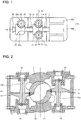
- Fig. 1 is an internal plan view illustrating a main configuration of a screw compressor according to Embodiment 1 of the present disclosure.
- Fig. 2 is a cross-sectional view of a portion corresponding to line A-A in Fig. 1 .
- the screw compressor of Embodiment 1 includes, inside casing 1, a low-stage compression unit 10 compressing refrigerant, and a high-stage compression unit 20 further compressing the refrigerant compressed by the low-stage compression unit 10.
- the screw compressor further includes a rotary shaft 30 that penetrates through the low-stage compression unit 10 and the high-stage compression unit 20 and is rotatably disposed inside the casing 1, and an electric motor 40 rotatably driving the rotary shaft 30.
- the low-stage compression unit 10 includes a low-stage screw rotor 11 and paired gate rotors 12.
- Each of the paired gate rotors 12 includes a plurality of radial teeth 12a engaging with a screw groove 11a provided in the low-stage screw rotor 11, and rotates by following rotation of the low-stage screw rotor 11.
- the paired gate rotors 12 are supported by paired gate rotor supports 13 as illustrated in Fig. 2 .
- Each of the gate rotor supports 13 is disposed to have a center axis substantially perpendicular to the rotary shaft 30.
- the low-stage compression unit 10 compresses the refrigerant in paired compression chambers formed by the screw groove 11a, the paired gate rotors 12, and the casing 1.
- the paired gate rotors 12 are disposed at positions mutually rotated by 180 degrees with the rotary shaft 30 as a center. Therefore, the paired compression chambers are formed at positions mutually rotated by 180 degrees with the rotary shaft 30 as a center.
- the high-stage compression unit 20 includes a high-stage screw rotor 21 and one gate rotor 22.
- the gate rotor 22 includes a plurality of radial teeth 22a engaging with a screw groove 21a provided in the high-stage screw rotor 21, and rotates by following rotation of the high-stage screw rotor 21.
- the gate rotor 22 is supported by a gate rotor support (not illustrated), and is disposed to have a center axis substantially perpendicular to the rotary shaft 30, in a manner similar to the gate rotors 12 of the low-stage compression unit 10.
- the high-stage compression unit 20 compresses the refrigerant in a compression chamber formed by the screw groove 21a, the gate rotor 22, and the casing 1. Since the high-stage compression unit 20 includes one gate rotor 12, one compression chamber is formed.
- the electric motor 40 includes a stator 40A that is fixed to the casing 1 while being in contact with an inside of the casing 1, and a motor rotor 40b disposed inside the stator 40a.
- the motor rotor 40b is fixed to the rotary shaft 30.
- the electric motor 40 is operated by increasing/decreasing rotation speed of the rotary shaft 30 with use of an unillustrated inverter.
- the low-stage screw rotor 11 and the high-stage screw rotor 21 are driven at variable rotation speed by the inverter.
- the electric motor 40 is not limited to an electric motor variable in rotation speed, and may be an electric motor fixed in rotation speed.
- the screw compressor having the above-described configuration uses "a single-component refrigerant of HFO1234ze or a refrigerant mixture containing HFO1234ze” (hereinafter, collectively referred to as HFO1234ze refrigerant) as the refrigerant, and uses a polyol ester oil as a refrigerating machine oil together, and is used by being incorporated in a refrigeration device.
- the screw compressor of Embodiment 1 uses an L-PPS resin for a sliding part of a sliding unit to prevent deterioration of the sliding part when the HFO1234ze refrigerant and the polyol ester oil are used in combination.
- the sliding unit includes, for example, a bearing unit. The bearing unit in the screw compressor is described below.
- the rotary shaft 30 is rotatably supported by a rolling bearing 51, a rolling bearing 52, and a rolling bearing 53.
- both ends of the rotary shaft 13a of each of the gate rotor supports 13 are rotatably supported by a rolling bearing 14 and a rolling bearing 15.
- both ends of a rotary shaft of the gate rotor support of the high-stage compression unit 20 are similarly supported by rolling bearings.
- Retainers of these rolling bearings are sliding parts, and the L-PPS resin is used as a material of all of the retainers of the rolling bearings in Embodiment 1.
- the L-PPS resin is a resin material that has a structure in which a molecular chain in polyphenylene sulfide (PPS) is increased in molecular weight to a straight chain, and has improved strength as compared with PPS.
- the L-PPS resin for the sliding part in the above-described manner makes it possible to prevent deterioration of the sliding part when the HFO1234ze refrigerant and the polyol ester oil are used in combination. Further, the L-PPS resin is higher in use temperature zone than a polyamide resin. Therefore, using the L-PPS resin as the material of the sliding part in the compressor is advantageous to heat generation caused by lubrication failure or the like.
- the electric motor 40 driving the screw compressor is activated in response to electrical input from the unillustrated inverter.
- the electric motor 40 When the electric motor 40 is activated, the rotary shaft 30 rotates, and the low-stage screw rotor 11 and the high-stage screw rotor 21 rotate through the rotary shaft 30.
- the low-stage screw rotor 11 rotates, the paired gate rotors 12 rotate.
- the gate rotor 22 rotates.
- the teeth 12a of the gate rotors 12 relatively move inside the screw groove 21a of the high-stage screw rotor 21.
- a suction process of suctioning the refrigerant into the compression chambers, a compression process of compressing the refrigerant inside the compression chambers, and a discharge process of discharging the refrigerant compressed inside the compression chambers are sequentially repeated.
- the refrigerant compressed in the low-stage compression unit 10 and then discharged is suctioned into the high-stage compression unit 20 and is further compressed.
- the teeth 12a of the gate rotor 12 relatively move inside the screw groove 21a of the high-stage screw rotor 21.
- a suction process of suctioning the refrigerant into the compression chamber, a compression process of compressing the refrigerant inside the compression chamber, and a discharge process of discharging the refrigerant compressed inside the compression chamber are sequentially repeated.
- the refrigerant compressed in the high-stage compression unit 20 is discharged to outside of the screw compressor.
- the retainers of the rolling bearings as the sliding parts are made of the L-PPS resin. This makes it possible to prevent deterioration of the sliding parts.
- the screw compressor that uses the HFO1234ze refrigerant and the polyol ester oil in combination strength degradation impairing reliability does not occur, and stable operation is performable.
- each of the rolling bearings serves as the sliding unit, and each of the retainers of the rolling bearings serves as the sliding part made of the L-PPS resin has been described; however, the sliding part is not limited thereto.
- the sliding part is a part sliding with the other part with rotation of the rotary shaft 30, and for example, the gate rotor is also included in the sliding part.
- the gate rotor corresponds to the sliding part because the gate rotor rotates with rotation of the rotary shaft 30 and slides while the teeth engage with the screw groove.
- the gate rotor may be made of the L-PPS resin.
- Embodiment 2 relates to a refrigeration device including the screw compressor of Embodiment 1.
- Fig. 3 is a diagram illustrating a refrigerant circuit of the refrigeration device including the screw compressor in Fig. 1 .
- a refrigeration device 200 includes the screw compressor 100 of Embodiment 1, a condenser 101, an expansion valve 102, and an evaporator 103, and includes a refrigerant circuit through which refrigerant circulates.
- the refrigeration device 200 uses the HFO1234ze refrigerant as the refrigerant.
- the polyol ester oil is used as a refrigerating machine oil circulating through the refrigerant circuit together with the refrigerant.
- the refrigerant circuit having the above-described configuration operates in the following manner.
- Gas refrigerant compressed and discharged from the screw compressor 100 flows into the condenser 101 and becomes high-pressure liquid refrigerant by exchanging heat with air passing through the condenser 101.
- the high-pressure liquid refrigerant then flows out from the condenser 101.
- the high-pressure liquid refrigerant having flowed out from the condenser 101 is decompressed by the expansion valve 102 to low-pressure two-phase gas-liquid refrigerant, and the low-pressure two-phase gas-liquid refrigerant flows into the evaporator 103.
- the low-pressure two-phase gas-liquid refrigerant having flowed into the evaporator 103 becomes low-pressure gas refrigerant by exchanging heat with air passing through the evaporator 103, and the low-pressure gas refrigerant is suctioned into the screw compressor 100 again.
- the refrigeration device 200 having the above-described configuration can perform stable operation with high reliability because the refrigeration device 200 includes the screw compressor 100 of Embodiment 1.
- the refrigeration device 200 is applicable to an air-conditioning apparatus, a refrigerator and freezer, and other apparatuses.
- the present disclosure is applied to the two-stage single screw compressor; however, the application is not limited to the two-stage single screw compressor, and the present disclosure may be applied to a single-stage single screw compressor. Further, the present disclosure may be applied to a twin screw compressor in which paired male and female screws engage with each other to form a compression chamber. Further, the application is not limited to the screw compressor, and the present disclosure may be applied to a rotary compressor, a scroll compressor, and the other types of compressors. In any cases, effects of the present disclosure are achievable.
Landscapes
- Engineering & Computer Science (AREA)
- General Engineering & Computer Science (AREA)
- Mechanical Engineering (AREA)
- Physics & Mathematics (AREA)
- Thermal Sciences (AREA)
- Applications Or Details Of Rotary Compressors (AREA)
- Compressor (AREA)
- Rolling Contact Bearings (AREA)
Abstract
Description
- The present disclosure relates to a compressor using a single-component refrigerant of HFO1234ze or a refrigerant mixture containing HFO1234ze, and to a refrigeration device including the compressor.
- A single-component refrigerant of HFO1234ze and a refrigerant mixture containing HFO1234ze have been used in a refrigeration cycle. It is known that these refrigerants are small in influence on ozone layer depletion, and is suitable for environment preservation. Here, HFO1234ze is represented by a molecular formula of C3HmFn (where m and n are each an integer of 1 or more and 5 or less, and relationship of m + n = 6 is established), and has one double bond in a molecular structure.
- In a case where a refrigeration device performing the refrigeration cycle uses, as the refrigerant, the single-component refrigerant of HFO1234ze or the refrigerant mixture containing HFO1234ze, a resin used in a sliding part of a sliding unit inside a compressor may be deteriorated depending on a combination with a refrigerating machine oil used to lubricate the sliding unit.
- Therefore, there is a technology in which the single-component refrigerant of HFO1234ze or the refrigerant mixture containing HFO1234ze is used as the refrigerant in combination with a polyol ester oil to prevent deterioration of the sliding part (for example, see Patent Literature 1).
- Patent Literature 1:
Japanese Patent No. 5304531 -
Patent Literature 1 described above discloses that the single-component refrigerant of HFO1234ze or the refrigerant mixture containing HFO1234ze is used in combination with the polyol ester oil, which makes it possible to prevent deterioration of the sliding part made of a polyamide resin. It is, however, confirmed from tests by the inventers of the present application that deterioration of the polyamide resin cannot be sufficiently prevented, and the use of the polyamide resin for the sliding part has an issue in terms of reliability. - The present disclosure is made in light of such an issue, and an object of the present disclosure is to provide a compressor that uses the single-component refrigerant of HFO1234ze or the refrigerant mixture containing HFO1234ze in combination with the polyol ester oil and can prevent deterioration of a sliding part, and to provide a refrigeration device including the compressor.
- A compressor according to an embodiment of the present disclosure is a compressor to be used in a refrigerant circuit that uses a single-component refrigerant of HFO1234ze or a refrigerant mixture containing HFO1234ze and uses a polyol ester oil as a refrigerating machine oil. The compressor includes a rotary shaft, and a sliding unit including a sliding part sliding with another part with rotation of the rotary shaft. The sliding part is made of an L-PPS resin obtained by increasing molecular weight of a PPS resin in a straight chain.
- According to the embodiment of the present disclosure, in the compressor that uses the single-component refrigerant of HFO1234ze or the refrigerant mixture containing HFO1234ze in combination with the polyol ester oil, the sliding part is made of the L-PPS resin. Therefore, it is possible to prevent deterioration of the sliding part. Brief Description of Drawings
-
- [
Fig. 1] Fig. 1 is an internal plan view illustrating a main configuration of a screw compressor according toEmbodiment 1 of the present disclosure. - [
Fig. 2] Fig. 2 is a cross-sectional view of a portion corresponding to line A-A inFig. 1 . - [
Fig. 3] Fig. 3 is a diagram illustrating a refrigerant circuit of a refrigeration device according to Embodiment 2 of the present disclosure. - Some embodiments of the present disclosure are described below with reference to drawings. In the drawings, the same reference numerals denote the same or equivalent components, and are used in common in an entire description of the present specification.
- In the following, an embodiment in which the present disclosure is applied to a two-stage single screw compressor (hereinafter, simply referred to as screw compressor) is described.
-
Fig. 1 is an internal plan view illustrating a main configuration of a screw compressor according toEmbodiment 1 of the present disclosure.Fig. 2 is a cross-sectional view of a portion corresponding to line A-A inFig. 1 . - First, the configuration of
Embodiment 1 is described. The screw compressor of Embodiment 1 includes, insidecasing 1, a low-stage compression unit 10 compressing refrigerant, and a high-stage compression unit 20 further compressing the refrigerant compressed by the low-stage compression unit 10. The screw compressor further includes arotary shaft 30 that penetrates through the low-stage compression unit 10 and the high-stage compression unit 20 and is rotatably disposed inside thecasing 1, and anelectric motor 40 rotatably driving therotary shaft 30. - The low-
stage compression unit 10 includes a low-stage screw rotor 11 and pairedgate rotors 12. Each of the pairedgate rotors 12 includes a plurality ofradial teeth 12a engaging with ascrew groove 11a provided in the low-stage screw rotor 11, and rotates by following rotation of the low-stage screw rotor 11. The pairedgate rotors 12 are supported by paired gate rotor supports 13 as illustrated inFig. 2 . Each of thegate rotor supports 13 is disposed to have a center axis substantially perpendicular to therotary shaft 30. The low-stage compression unit 10 compresses the refrigerant in paired compression chambers formed by thescrew groove 11a, the pairedgate rotors 12, and thecasing 1. In the low-stage compression unit 10, the pairedgate rotors 12 are disposed at positions mutually rotated by 180 degrees with therotary shaft 30 as a center. Therefore, the paired compression chambers are formed at positions mutually rotated by 180 degrees with therotary shaft 30 as a center. - The high-
stage compression unit 20 includes a high-stage screw rotor 21 and onegate rotor 22. Thegate rotor 22 includes a plurality ofradial teeth 22a engaging with ascrew groove 21a provided in the high-stage screw rotor 21, and rotates by following rotation of the high-stage screw rotor 21. Thegate rotor 22 is supported by a gate rotor support (not illustrated), and is disposed to have a center axis substantially perpendicular to therotary shaft 30, in a manner similar to thegate rotors 12 of the low-stage compression unit 10. The high-stage compression unit 20 compresses the refrigerant in a compression chamber formed by thescrew groove 21a, thegate rotor 22, and thecasing 1. Since the high-stage compression unit 20 includes onegate rotor 12, one compression chamber is formed. - The
electric motor 40 includes a stator 40A that is fixed to thecasing 1 while being in contact with an inside of thecasing 1, and amotor rotor 40b disposed inside thestator 40a. Themotor rotor 40b is fixed to therotary shaft 30. When theelectric motor 40 is driven and therotary shaft 30 rotates, the low-stage screw rotor 11 and the high-stage screw rotor 21 rotate. - The
electric motor 40 is operated by increasing/decreasing rotation speed of therotary shaft 30 with use of an unillustrated inverter. In other words, the low-stage screw rotor 11 and the high-stage screw rotor 21 are driven at variable rotation speed by the inverter. Note that theelectric motor 40 is not limited to an electric motor variable in rotation speed, and may be an electric motor fixed in rotation speed. - The screw compressor having the above-described configuration uses "a single-component refrigerant of HFO1234ze or a refrigerant mixture containing HFO1234ze" (hereinafter, collectively referred to as HFO1234ze refrigerant) as the refrigerant, and uses a polyol ester oil as a refrigerating machine oil together, and is used by being incorporated in a refrigeration device. Here, HFO1234ze is represented by a molecular formula of C3HmFn (where m and n are each an integer of 1 or more and 5 or less, and relationship of m + n = 6 is established), and has one double bond in a molecular structure.
- Further, the screw compressor of Embodiment 1 uses an L-PPS resin for a sliding part of a sliding unit to prevent deterioration of the sliding part when the HFO1234ze refrigerant and the polyol ester oil are used in combination. The sliding unit includes, for example, a bearing unit. The bearing unit in the screw compressor is described below.
- As illustrated in
Fig. 1 , therotary shaft 30 is rotatably supported by a rollingbearing 51, a rollingbearing 52, and a rollingbearing 53. Further, as illustrated inFig. 2 , both ends of therotary shaft 13a of each of thegate rotor supports 13 are rotatably supported by a rollingbearing 14 and a rollingbearing 15. Although not illustrated, both ends of a rotary shaft of the gate rotor support of the high-stage compression unit 20 are similarly supported by rolling bearings. Retainers of these rolling bearings are sliding parts, and the L-PPS resin is used as a material of all of the retainers of the rolling bearings inEmbodiment 1. The L-PPS resin is a resin material that has a structure in which a molecular chain in polyphenylene sulfide (PPS) is increased in molecular weight to a straight chain, and has improved strength as compared with PPS. - Using the L-PPS resin for the sliding part in the above-described manner makes it possible to prevent deterioration of the sliding part when the HFO1234ze refrigerant and the polyol ester oil are used in combination. Further, the L-PPS resin is higher in use temperature zone than a polyamide resin. Therefore, using the L-PPS resin as the material of the sliding part in the compressor is advantageous to heat generation caused by lubrication failure or the like.
- Next, operation of the screw compressor according to
Embodiment 1 is described. - The
electric motor 40 driving the screw compressor is activated in response to electrical input from the unillustrated inverter. When theelectric motor 40 is activated, therotary shaft 30 rotates, and the low-stage screw rotor 11 and the high-stage screw rotor 21 rotate through therotary shaft 30. When the low-stage screw rotor 11 rotates, the pairedgate rotors 12 rotate. In addition, when the high-stage screw rotor 21 rotates, thegate rotor 22 rotates. - In the low-
stage compression unit 10, theteeth 12a of thegate rotors 12 relatively move inside thescrew groove 21a of the high-stage screw rotor 21. As a result, in the low-stage compression unit 10, a suction process of suctioning the refrigerant into the compression chambers, a compression process of compressing the refrigerant inside the compression chambers, and a discharge process of discharging the refrigerant compressed inside the compression chambers are sequentially repeated. The refrigerant compressed in the low-stage compression unit 10 and then discharged is suctioned into the high-stage compression unit 20 and is further compressed. - In the high-
stage compression unit 20, theteeth 12a of thegate rotor 12 relatively move inside thescrew groove 21a of the high-stage screw rotor 21. As a result, in the high-stage compression unit 20, a suction process of suctioning the refrigerant into the compression chamber, a compression process of compressing the refrigerant inside the compression chamber, and a discharge process of discharging the refrigerant compressed inside the compression chamber are sequentially repeated. The refrigerant compressed in the high-stage compression unit 20 is discharged to outside of the screw compressor. - In the above-described operation of the screw compressor, a gas load by gas compression action of the low-
stage compression unit 10 and the high-stage compression unit 20 is supported by the rolling bearings. Further, in the screw compressor, the refrigerating machine oil is suctioned together with the refrigerant into the low-stage compression unit 10 and the high-stage compression unit 20, and the rolling bearings are lubricated by the refrigerating machine oil. At this time, since the retainers of the respective rolling bearings are made of the L-PPS resin as described above, it is possible to prevent deterioration when the HFO1234ze refrigerant and the polyol ester oil are used in combination. - As described above, according to
Embodiment 1, in the screw compressor that uses the HFO1234ze refrigerant as the refrigerant and uses the polyol ester oil as the refrigerating machine oil, the retainers of the rolling bearings as the sliding parts are made of the L-PPS resin. This makes it possible to prevent deterioration of the sliding parts. In other words, in the screw compressor that uses the HFO1234ze refrigerant and the polyol ester oil in combination, strength degradation impairing reliability does not occur, and stable operation is performable. - In the above description, the example in which each of the rolling bearings serves as the sliding unit, and each of the retainers of the rolling bearings serves as the sliding part made of the L-PPS resin has been described; however, the sliding part is not limited thereto. The sliding part is a part sliding with the other part with rotation of the
rotary shaft 30, and for example, the gate rotor is also included in the sliding part. The gate rotor corresponds to the sliding part because the gate rotor rotates with rotation of therotary shaft 30 and slides while the teeth engage with the screw groove. The gate rotor may be made of the L-PPS resin. - Embodiment 2 relates to a refrigeration device including the screw compressor of
Embodiment 1. -
Fig. 3 is a diagram illustrating a refrigerant circuit of the refrigeration device including the screw compressor inFig. 1 . - A
refrigeration device 200 includes thescrew compressor 100 ofEmbodiment 1, acondenser 101, anexpansion valve 102, and anevaporator 103, and includes a refrigerant circuit through which refrigerant circulates. Therefrigeration device 200 uses the HFO1234ze refrigerant as the refrigerant. In addition, the polyol ester oil is used as a refrigerating machine oil circulating through the refrigerant circuit together with the refrigerant. - The refrigerant circuit having the above-described configuration operates in the following manner.
- Gas refrigerant compressed and discharged from the
screw compressor 100 flows into thecondenser 101 and becomes high-pressure liquid refrigerant by exchanging heat with air passing through thecondenser 101. The high-pressure liquid refrigerant then flows out from thecondenser 101. The high-pressure liquid refrigerant having flowed out from thecondenser 101 is decompressed by theexpansion valve 102 to low-pressure two-phase gas-liquid refrigerant, and the low-pressure two-phase gas-liquid refrigerant flows into theevaporator 103. The low-pressure two-phase gas-liquid refrigerant having flowed into theevaporator 103 becomes low-pressure gas refrigerant by exchanging heat with air passing through theevaporator 103, and the low-pressure gas refrigerant is suctioned into thescrew compressor 100 again. - The
refrigeration device 200 having the above-described configuration can perform stable operation with high reliability because therefrigeration device 200 includes thescrew compressor 100 ofEmbodiment 1. - The
refrigeration device 200 is applicable to an air-conditioning apparatus, a refrigerator and freezer, and other apparatuses. - In
Embodiment 1 and Embodiment 2 described above, the present disclosure is applied to the two-stage single screw compressor; however, the application is not limited to the two-stage single screw compressor, and the present disclosure may be applied to a single-stage single screw compressor. Further, the present disclosure may be applied to a twin screw compressor in which paired male and female screws engage with each other to form a compression chamber. Further, the application is not limited to the screw compressor, and the present disclosure may be applied to a rotary compressor, a scroll compressor, and the other types of compressors. In any cases, effects of the present disclosure are achievable. -
- 1 casing 10 low-
stage compression unit 11 low-stage screw rotor -
11a screw groove 12gate 13 gate rotor supportrotor 12a tooth - 13a
rotary shaft 14 rollingbearing 15 rollingbearing 20 high-stage compression unit 21 high-stage screw rotor 21a screw groove 22gate 30rotor 22a toothrotary shaft 40electric 40b motor rotormotor 40a stator - 51 rolling
bearing 52 rollingbearing53 rolling bearing 100screw compressor 101condenser 102expansion valve 103evaporator 200 refrigeration device
Claims (3)
- A compressor to be used in a refrigerant circuit that uses a single-component refrigerant of HFO1234ze or a refrigerant mixture containing HFO1234ze and uses a polyol ester oil as a refrigerating machine oil, the compressor comprising:a rotary shaft; anda sliding unit including a sliding part sliding with another part with rotation of the rotary shaft, the sliding part being made of an L-PPS resin obtained by increasing molecular weight of a PPS resin in a straight chain.
- The compressor of claim 1, wherein the sliding unit is a rolling bearing supporting the rotary shaft, and a retainer of the rolling bearing is made of the L-PPS resin.
- A refrigeration device comprising the compressor of claim 1 or 2.
Applications Claiming Priority (1)
| Application Number | Priority Date | Filing Date | Title |
|---|---|---|---|
| PCT/JP2018/037548 WO2020075218A1 (en) | 2018-10-09 | 2018-10-09 | Compressor and refrigeration device provided with compressor |
Publications (3)
| Publication Number | Publication Date |
|---|---|
| EP3865785A1 true EP3865785A1 (en) | 2021-08-18 |
| EP3865785A4 EP3865785A4 (en) | 2021-10-27 |
| EP3865785B1 EP3865785B1 (en) | 2024-04-03 |
Family
ID=70164623
Family Applications (1)
| Application Number | Title | Priority Date | Filing Date |
|---|---|---|---|
| EP18936425.0A Active EP3865785B1 (en) | 2018-10-09 | 2018-10-09 | Compressor and refrigeration device provided with compressor |
Country Status (4)
| Country | Link |
|---|---|
| EP (1) | EP3865785B1 (en) |
| JP (1) | JPWO2020075218A1 (en) |
| TW (1) | TWI709721B (en) |
| WO (1) | WO2020075218A1 (en) |
Family Cites Families (12)
| Publication number | Priority date | Publication date | Assignee | Title |
|---|---|---|---|---|
| JPS534531B2 (en) | 1972-04-26 | 1978-02-18 | ||
| JP2009174460A (en) * | 2008-01-25 | 2009-08-06 | Daikin Ind Ltd | Screw compressor |
| JP2009203817A (en) * | 2008-02-26 | 2009-09-10 | Daikin Ind Ltd | Gate rotor and screw compressor |
| JP5361047B2 (en) * | 2008-12-25 | 2013-12-04 | 東芝キヤリア株式会社 | Rotary fluid machine and refrigeration cycle apparatus |
| JP5304531B2 (en) * | 2009-08-20 | 2013-10-02 | ダイキン工業株式会社 | Refrigeration equipment |
| JP5393549B2 (en) * | 2010-03-16 | 2014-01-22 | 三菱電機株式会社 | Single screw compressor and refrigeration cycle apparatus equipped with the single screw compressor |
| JP5466772B2 (en) * | 2010-12-20 | 2014-04-09 | 日立アプライアンス株式会社 | Compressor for refrigeration and air-conditioning equipment |
| JP2012167667A (en) * | 2011-01-28 | 2012-09-06 | Nsk Ltd | Rotary compressor |
| JP2013002295A (en) * | 2011-06-13 | 2013-01-07 | Daikin Industries Ltd | Screw compressor |
| JP5562920B2 (en) * | 2011-09-30 | 2014-07-30 | 日立アプライアンス株式会社 | Compressor for refrigeration and air-conditioning equipment |
| JP2013133374A (en) * | 2011-12-26 | 2013-07-08 | Toray Ind Inc | Polyphenylene sulfide resin composition and molding formed therefrom |
| CN110446858B (en) * | 2017-03-21 | 2021-08-03 | 大金工业株式会社 | single screw compressor |
-
2018
- 2018-10-09 WO PCT/JP2018/037548 patent/WO2020075218A1/en not_active Ceased
- 2018-10-09 JP JP2020551074A patent/JPWO2020075218A1/en active Pending
- 2018-10-09 EP EP18936425.0A patent/EP3865785B1/en active Active
-
2019
- 2019-08-22 TW TW108129994A patent/TWI709721B/en active
Also Published As
| Publication number | Publication date |
|---|---|
| JPWO2020075218A1 (en) | 2021-09-02 |
| TW202014653A (en) | 2020-04-16 |
| WO2020075218A1 (en) | 2020-04-16 |
| EP3865785B1 (en) | 2024-04-03 |
| EP3865785A4 (en) | 2021-10-27 |
| TWI709721B (en) | 2020-11-11 |
Similar Documents
| Publication | Publication Date | Title |
|---|---|---|
| US20250189183A1 (en) | Turbo chiller | |
| US10801495B2 (en) | Oil flow through the bearings of a scroll compressor | |
| CN101008389B (en) | Hermetic rotary compressor and refrigeration cycle device having hermetic rotary compressor | |
| US8939742B2 (en) | Compressor with steel and cast iron sliding materials | |
| CN109072895B (en) | Electric compressors and refrigeration and air-conditioning units | |
| US9695823B2 (en) | Compressor with unloader counterweight assembly | |
| JP5656691B2 (en) | Refrigeration equipment | |
| CN102062090A (en) | Scroll compressor | |
| US11286936B2 (en) | Scroll compressor | |
| JP6759388B2 (en) | Centrifugal chiller | |
| EP3865785B1 (en) | Compressor and refrigeration device provided with compressor | |
| US20200200181A1 (en) | Oil Control For Climate-Control System | |
| WO2015114783A1 (en) | Compressor and refrigeration cycle device | |
| JP2019090602A (en) | Turbo refrigerator | |
| JP2010255448A (en) | Rotary compressor | |
| US11293438B2 (en) | Screw compressor with magnetic gear | |
| JP5911637B2 (en) | Compressor | |
| JP2018040324A (en) | Compressor | |
| US12104594B2 (en) | Co-rotating compressor | |
| US11815090B2 (en) | Scroll compressor | |
| EP4484752A1 (en) | Screw compressor and freezer | |
| KR102825794B1 (en) | Electric compressor | |
| EP3617513A1 (en) | Compressor and refrigeration cycle device | |
| US20210285446A1 (en) | Compressor arrangement with integrated motor | |
| US11162495B2 (en) | Oil circulation in a scroll compressor |
Legal Events
| Date | Code | Title | Description |
|---|---|---|---|
| STAA | Information on the status of an ep patent application or granted ep patent |
Free format text: STATUS: THE INTERNATIONAL PUBLICATION HAS BEEN MADE |
|
| PUAI | Public reference made under article 153(3) epc to a published international application that has entered the european phase |
Free format text: ORIGINAL CODE: 0009012 |
|
| STAA | Information on the status of an ep patent application or granted ep patent |
Free format text: STATUS: REQUEST FOR EXAMINATION WAS MADE |
|
| 17P | Request for examination filed |
Effective date: 20210215 |
|
| AK | Designated contracting states |
Kind code of ref document: A1 Designated state(s): AL AT BE BG CH CY CZ DE DK EE ES FI FR GB GR HR HU IE IS IT LI LT LU LV MC MK MT NL NO PL PT RO RS SE SI SK SM TR |
|
| A4 | Supplementary search report drawn up and despatched |
Effective date: 20210924 |
|
| RIC1 | Information provided on ipc code assigned before grant |
Ipc: F04C 18/52 20060101ALI20210920BHEP Ipc: F25B 1/00 20060101ALI20210920BHEP Ipc: F16C 33/56 20060101ALI20210920BHEP Ipc: F16C 33/14 20060101ALI20210920BHEP Ipc: F04B 39/00 20060101ALI20210920BHEP Ipc: F25B 1/04 20060101AFI20210920BHEP |
|
| DAV | Request for validation of the european patent (deleted) | ||
| DAX | Request for extension of the european patent (deleted) | ||
| GRAP | Despatch of communication of intention to grant a patent |
Free format text: ORIGINAL CODE: EPIDOSNIGR1 |
|
| STAA | Information on the status of an ep patent application or granted ep patent |
Free format text: STATUS: GRANT OF PATENT IS INTENDED |
|
| INTG | Intention to grant announced |
Effective date: 20231016 |
|
| P01 | Opt-out of the competence of the unified patent court (upc) registered |
Effective date: 20231122 |
|
| GRAS | Grant fee paid |
Free format text: ORIGINAL CODE: EPIDOSNIGR3 |
|
| GRAA | (expected) grant |
Free format text: ORIGINAL CODE: 0009210 |
|
| STAA | Information on the status of an ep patent application or granted ep patent |
Free format text: STATUS: THE PATENT HAS BEEN GRANTED |
|
| AK | Designated contracting states |
Kind code of ref document: B1 Designated state(s): AL AT BE BG CH CY CZ DE DK EE ES FI FR GB GR HR HU IE IS IT LI LT LU LV MC MK MT NL NO PL PT RO RS SE SI SK SM TR |
|
| REG | Reference to a national code |
Ref country code: GB Ref legal event code: FG4D |
|
| REG | Reference to a national code |
Ref country code: CH Ref legal event code: EP |
|
| REG | Reference to a national code |
Ref country code: DE Ref legal event code: R096 Ref document number: 602018067722 Country of ref document: DE |
|
| REG | Reference to a national code |
Ref country code: IE Ref legal event code: FG4D |
|
| REG | Reference to a national code |
Ref country code: LT Ref legal event code: MG9D |
|
| REG | Reference to a national code |
Ref country code: NL Ref legal event code: MP Effective date: 20240403 |
|
| REG | Reference to a national code |
Ref country code: AT Ref legal event code: MK05 Ref document number: 1672732 Country of ref document: AT Kind code of ref document: T Effective date: 20240403 |
|
| PG25 | Lapsed in a contracting state [announced via postgrant information from national office to epo] |
Ref country code: NL Free format text: LAPSE BECAUSE OF FAILURE TO SUBMIT A TRANSLATION OF THE DESCRIPTION OR TO PAY THE FEE WITHIN THE PRESCRIBED TIME-LIMIT Effective date: 20240403 |
|
| PG25 | Lapsed in a contracting state [announced via postgrant information from national office to epo] |
Ref country code: NL Free format text: LAPSE BECAUSE OF FAILURE TO SUBMIT A TRANSLATION OF THE DESCRIPTION OR TO PAY THE FEE WITHIN THE PRESCRIBED TIME-LIMIT Effective date: 20240403 |
|
| PG25 | Lapsed in a contracting state [announced via postgrant information from national office to epo] |
Ref country code: IS Free format text: LAPSE BECAUSE OF FAILURE TO SUBMIT A TRANSLATION OF THE DESCRIPTION OR TO PAY THE FEE WITHIN THE PRESCRIBED TIME-LIMIT Effective date: 20240803 |
|
| PG25 | Lapsed in a contracting state [announced via postgrant information from national office to epo] |
Ref country code: BG Free format text: LAPSE BECAUSE OF FAILURE TO SUBMIT A TRANSLATION OF THE DESCRIPTION OR TO PAY THE FEE WITHIN THE PRESCRIBED TIME-LIMIT Effective date: 20240403 |
|
| PG25 | Lapsed in a contracting state [announced via postgrant information from national office to epo] |
Ref country code: HR Free format text: LAPSE BECAUSE OF FAILURE TO SUBMIT A TRANSLATION OF THE DESCRIPTION OR TO PAY THE FEE WITHIN THE PRESCRIBED TIME-LIMIT Effective date: 20240403 Ref country code: FI Free format text: LAPSE BECAUSE OF FAILURE TO SUBMIT A TRANSLATION OF THE DESCRIPTION OR TO PAY THE FEE WITHIN THE PRESCRIBED TIME-LIMIT Effective date: 20240403 |
|
| PG25 | Lapsed in a contracting state [announced via postgrant information from national office to epo] |
Ref country code: GR Free format text: LAPSE BECAUSE OF FAILURE TO SUBMIT A TRANSLATION OF THE DESCRIPTION OR TO PAY THE FEE WITHIN THE PRESCRIBED TIME-LIMIT Effective date: 20240704 |
|
| PG25 | Lapsed in a contracting state [announced via postgrant information from national office to epo] |
Ref country code: PT Free format text: LAPSE BECAUSE OF FAILURE TO SUBMIT A TRANSLATION OF THE DESCRIPTION OR TO PAY THE FEE WITHIN THE PRESCRIBED TIME-LIMIT Effective date: 20240805 |
|
| PG25 | Lapsed in a contracting state [announced via postgrant information from national office to epo] |
Ref country code: ES Free format text: LAPSE BECAUSE OF FAILURE TO SUBMIT A TRANSLATION OF THE DESCRIPTION OR TO PAY THE FEE WITHIN THE PRESCRIBED TIME-LIMIT Effective date: 20240403 |
|
| PG25 | Lapsed in a contracting state [announced via postgrant information from national office to epo] |
Ref country code: CZ Free format text: LAPSE BECAUSE OF FAILURE TO SUBMIT A TRANSLATION OF THE DESCRIPTION OR TO PAY THE FEE WITHIN THE PRESCRIBED TIME-LIMIT Effective date: 20240403 |
|
| PG25 | Lapsed in a contracting state [announced via postgrant information from national office to epo] |
Ref country code: AT Free format text: LAPSE BECAUSE OF FAILURE TO SUBMIT A TRANSLATION OF THE DESCRIPTION OR TO PAY THE FEE WITHIN THE PRESCRIBED TIME-LIMIT Effective date: 20240403 |
|
| PG25 | Lapsed in a contracting state [announced via postgrant information from national office to epo] |
Ref country code: PL Free format text: LAPSE BECAUSE OF FAILURE TO SUBMIT A TRANSLATION OF THE DESCRIPTION OR TO PAY THE FEE WITHIN THE PRESCRIBED TIME-LIMIT Effective date: 20240403 |
|
| PG25 | Lapsed in a contracting state [announced via postgrant information from national office to epo] |
Ref country code: LV Free format text: LAPSE BECAUSE OF FAILURE TO SUBMIT A TRANSLATION OF THE DESCRIPTION OR TO PAY THE FEE WITHIN THE PRESCRIBED TIME-LIMIT Effective date: 20240403 |
|
| PG25 | Lapsed in a contracting state [announced via postgrant information from national office to epo] |
Ref country code: PT Free format text: LAPSE BECAUSE OF FAILURE TO SUBMIT A TRANSLATION OF THE DESCRIPTION OR TO PAY THE FEE WITHIN THE PRESCRIBED TIME-LIMIT Effective date: 20240805 Ref country code: PL Free format text: LAPSE BECAUSE OF FAILURE TO SUBMIT A TRANSLATION OF THE DESCRIPTION OR TO PAY THE FEE WITHIN THE PRESCRIBED TIME-LIMIT Effective date: 20240403 Ref country code: NO Free format text: LAPSE BECAUSE OF FAILURE TO SUBMIT A TRANSLATION OF THE DESCRIPTION OR TO PAY THE FEE WITHIN THE PRESCRIBED TIME-LIMIT Effective date: 20240703 Ref country code: LV Free format text: LAPSE BECAUSE OF FAILURE TO SUBMIT A TRANSLATION OF THE DESCRIPTION OR TO PAY THE FEE WITHIN THE PRESCRIBED TIME-LIMIT Effective date: 20240403 Ref country code: IS Free format text: LAPSE BECAUSE OF FAILURE TO SUBMIT A TRANSLATION OF THE DESCRIPTION OR TO PAY THE FEE WITHIN THE PRESCRIBED TIME-LIMIT Effective date: 20240803 Ref country code: HR Free format text: LAPSE BECAUSE OF FAILURE TO SUBMIT A TRANSLATION OF THE DESCRIPTION OR TO PAY THE FEE WITHIN THE PRESCRIBED TIME-LIMIT Effective date: 20240403 Ref country code: GR Free format text: LAPSE BECAUSE OF FAILURE TO SUBMIT A TRANSLATION OF THE DESCRIPTION OR TO PAY THE FEE WITHIN THE PRESCRIBED TIME-LIMIT Effective date: 20240704 Ref country code: FI Free format text: LAPSE BECAUSE OF FAILURE TO SUBMIT A TRANSLATION OF THE DESCRIPTION OR TO PAY THE FEE WITHIN THE PRESCRIBED TIME-LIMIT Effective date: 20240403 Ref country code: ES Free format text: LAPSE BECAUSE OF FAILURE TO SUBMIT A TRANSLATION OF THE DESCRIPTION OR TO PAY THE FEE WITHIN THE PRESCRIBED TIME-LIMIT Effective date: 20240403 Ref country code: CZ Free format text: LAPSE BECAUSE OF FAILURE TO SUBMIT A TRANSLATION OF THE DESCRIPTION OR TO PAY THE FEE WITHIN THE PRESCRIBED TIME-LIMIT Effective date: 20240403 Ref country code: BG Free format text: LAPSE BECAUSE OF FAILURE TO SUBMIT A TRANSLATION OF THE DESCRIPTION OR TO PAY THE FEE WITHIN THE PRESCRIBED TIME-LIMIT Effective date: 20240403 Ref country code: AT Free format text: LAPSE BECAUSE OF FAILURE TO SUBMIT A TRANSLATION OF THE DESCRIPTION OR TO PAY THE FEE WITHIN THE PRESCRIBED TIME-LIMIT Effective date: 20240403 Ref country code: RS Free format text: LAPSE BECAUSE OF FAILURE TO SUBMIT A TRANSLATION OF THE DESCRIPTION OR TO PAY THE FEE WITHIN THE PRESCRIBED TIME-LIMIT Effective date: 20240703 |
|
| REG | Reference to a national code |
Ref country code: DE Ref legal event code: R097 Ref document number: 602018067722 Country of ref document: DE |
|
| PG25 | Lapsed in a contracting state [announced via postgrant information from national office to epo] |
Ref country code: DK Free format text: LAPSE BECAUSE OF FAILURE TO SUBMIT A TRANSLATION OF THE DESCRIPTION OR TO PAY THE FEE WITHIN THE PRESCRIBED TIME-LIMIT Effective date: 20240403 |
|
| PG25 | Lapsed in a contracting state [announced via postgrant information from national office to epo] |
Ref country code: EE Free format text: LAPSE BECAUSE OF FAILURE TO SUBMIT A TRANSLATION OF THE DESCRIPTION OR TO PAY THE FEE WITHIN THE PRESCRIBED TIME-LIMIT Effective date: 20240403 |
|
| PG25 | Lapsed in a contracting state [announced via postgrant information from national office to epo] |
Ref country code: SK Free format text: LAPSE BECAUSE OF FAILURE TO SUBMIT A TRANSLATION OF THE DESCRIPTION OR TO PAY THE FEE WITHIN THE PRESCRIBED TIME-LIMIT Effective date: 20240403 Ref country code: RO Free format text: LAPSE BECAUSE OF FAILURE TO SUBMIT A TRANSLATION OF THE DESCRIPTION OR TO PAY THE FEE WITHIN THE PRESCRIBED TIME-LIMIT Effective date: 20240403 |
|
| PG25 | Lapsed in a contracting state [announced via postgrant information from national office to epo] |
Ref country code: SM Free format text: LAPSE BECAUSE OF FAILURE TO SUBMIT A TRANSLATION OF THE DESCRIPTION OR TO PAY THE FEE WITHIN THE PRESCRIBED TIME-LIMIT Effective date: 20240403 |
|
| PG25 | Lapsed in a contracting state [announced via postgrant information from national office to epo] |
Ref country code: SM Free format text: LAPSE BECAUSE OF FAILURE TO SUBMIT A TRANSLATION OF THE DESCRIPTION OR TO PAY THE FEE WITHIN THE PRESCRIBED TIME-LIMIT Effective date: 20240403 Ref country code: SK Free format text: LAPSE BECAUSE OF FAILURE TO SUBMIT A TRANSLATION OF THE DESCRIPTION OR TO PAY THE FEE WITHIN THE PRESCRIBED TIME-LIMIT Effective date: 20240403 Ref country code: RO Free format text: LAPSE BECAUSE OF FAILURE TO SUBMIT A TRANSLATION OF THE DESCRIPTION OR TO PAY THE FEE WITHIN THE PRESCRIBED TIME-LIMIT Effective date: 20240403 Ref country code: EE Free format text: LAPSE BECAUSE OF FAILURE TO SUBMIT A TRANSLATION OF THE DESCRIPTION OR TO PAY THE FEE WITHIN THE PRESCRIBED TIME-LIMIT Effective date: 20240403 Ref country code: DK Free format text: LAPSE BECAUSE OF FAILURE TO SUBMIT A TRANSLATION OF THE DESCRIPTION OR TO PAY THE FEE WITHIN THE PRESCRIBED TIME-LIMIT Effective date: 20240403 |
|
| PLBE | No opposition filed within time limit |
Free format text: ORIGINAL CODE: 0009261 |
|
| STAA | Information on the status of an ep patent application or granted ep patent |
Free format text: STATUS: NO OPPOSITION FILED WITHIN TIME LIMIT |
|
| 26N | No opposition filed |
Effective date: 20250106 |
|
| PG25 | Lapsed in a contracting state [announced via postgrant information from national office to epo] |
Ref country code: SI Free format text: LAPSE BECAUSE OF FAILURE TO SUBMIT A TRANSLATION OF THE DESCRIPTION OR TO PAY THE FEE WITHIN THE PRESCRIBED TIME-LIMIT Effective date: 20240403 |
|
| REG | Reference to a national code |
Ref country code: DE Ref legal event code: R119 Ref document number: 602018067722 Country of ref document: DE |
|
| REG | Reference to a national code |
Ref country code: CH Ref legal event code: PL |
|
| GBPC | Gb: european patent ceased through non-payment of renewal fee |
Effective date: 20241009 |
|
| PG25 | Lapsed in a contracting state [announced via postgrant information from national office to epo] |
Ref country code: MC Free format text: LAPSE BECAUSE OF FAILURE TO SUBMIT A TRANSLATION OF THE DESCRIPTION OR TO PAY THE FEE WITHIN THE PRESCRIBED TIME-LIMIT Effective date: 20240403 |
|
| PG25 | Lapsed in a contracting state [announced via postgrant information from national office to epo] |
Ref country code: DE Free format text: LAPSE BECAUSE OF NON-PAYMENT OF DUE FEES Effective date: 20250501 |
|
| PG25 | Lapsed in a contracting state [announced via postgrant information from national office to epo] |
Ref country code: GB Free format text: LAPSE BECAUSE OF NON-PAYMENT OF DUE FEES Effective date: 20241009 |
|
| PG25 | Lapsed in a contracting state [announced via postgrant information from national office to epo] |
Ref country code: LU Free format text: LAPSE BECAUSE OF NON-PAYMENT OF DUE FEES Effective date: 20241009 Ref country code: BE Free format text: LAPSE BECAUSE OF NON-PAYMENT OF DUE FEES Effective date: 20241031 |
|
| PG25 | Lapsed in a contracting state [announced via postgrant information from national office to epo] |
Ref country code: FR Free format text: LAPSE BECAUSE OF NON-PAYMENT OF DUE FEES Effective date: 20241031 |
|
| PG25 | Lapsed in a contracting state [announced via postgrant information from national office to epo] |
Ref country code: CH Free format text: LAPSE BECAUSE OF NON-PAYMENT OF DUE FEES Effective date: 20241031 |
|
| REG | Reference to a national code |
Ref country code: BE Ref legal event code: MM Effective date: 20241031 |
|
| PG25 | Lapsed in a contracting state [announced via postgrant information from national office to epo] |
Ref country code: SE Free format text: LAPSE BECAUSE OF FAILURE TO SUBMIT A TRANSLATION OF THE DESCRIPTION OR TO PAY THE FEE WITHIN THE PRESCRIBED TIME-LIMIT Effective date: 20240403 |
|
| PG25 | Lapsed in a contracting state [announced via postgrant information from national office to epo] |
Ref country code: IE Free format text: LAPSE BECAUSE OF NON-PAYMENT OF DUE FEES Effective date: 20241009 |
|
| PG25 | Lapsed in a contracting state [announced via postgrant information from national office to epo] |
Ref country code: IT Free format text: LAPSE BECAUSE OF NON-PAYMENT OF DUE FEES Effective date: 20241009 |
|
| PG25 | Lapsed in a contracting state [announced via postgrant information from national office to epo] |
Ref country code: CY Free format text: LAPSE BECAUSE OF FAILURE TO SUBMIT A TRANSLATION OF THE DESCRIPTION OR TO PAY THE FEE WITHIN THE PRESCRIBED TIME-LIMIT; INVALID AB INITIO Effective date: 20181009 |
|
| PG25 | Lapsed in a contracting state [announced via postgrant information from national office to epo] |
Ref country code: HU Free format text: LAPSE BECAUSE OF FAILURE TO SUBMIT A TRANSLATION OF THE DESCRIPTION OR TO PAY THE FEE WITHIN THE PRESCRIBED TIME-LIMIT; INVALID AB INITIO Effective date: 20181009 |
|
| PG25 | Lapsed in a contracting state [announced via postgrant information from national office to epo] |
Ref country code: IT Free format text: LAPSE BECAUSE OF NON-PAYMENT OF DUE FEES Effective date: 20241009 |
|
| PGFP | Annual fee paid to national office [announced via postgrant information from national office to epo] |
Ref country code: IT Payment date: 20250922 Year of fee payment: 8 |
|
| PGRI | Patent reinstated in contracting state [announced from national office to epo] |
Ref country code: IT Effective date: 20250228 |