EP3865731A1 - Parallel link mechanism and link action device - Google Patents
Parallel link mechanism and link action device Download PDFInfo
- Publication number
- EP3865731A1 EP3865731A1 EP19871283.8A EP19871283A EP3865731A1 EP 3865731 A1 EP3865731 A1 EP 3865731A1 EP 19871283 A EP19871283 A EP 19871283A EP 3865731 A1 EP3865731 A1 EP 3865731A1
- Authority
- EP
- European Patent Office
- Prior art keywords
- link
- end member
- revolute pair
- distal end
- proximal end
- Prior art date
- Legal status (The legal status is an assumption and is not a legal conclusion. Google has not performed a legal analysis and makes no representation as to the accuracy of the status listed.)
- Granted
Links
Images











Classifications
-
- F—MECHANICAL ENGINEERING; LIGHTING; HEATING; WEAPONS; BLASTING
- F16—ENGINEERING ELEMENTS AND UNITS; GENERAL MEASURES FOR PRODUCING AND MAINTAINING EFFECTIVE FUNCTIONING OF MACHINES OR INSTALLATIONS; THERMAL INSULATION IN GENERAL
- F16H—GEARING
- F16H21/00—Gearings comprising primarily only links or levers, with or without slides
- F16H21/46—Gearings comprising primarily only links or levers, with or without slides with movements in three dimensions [3D]
- F16H21/54—Gearings comprising primarily only links or levers, with or without slides with movements in three dimensions [3D] for conveying or interconverting oscillating or reciprocating motions
-
- F—MECHANICAL ENGINEERING; LIGHTING; HEATING; WEAPONS; BLASTING
- F16—ENGINEERING ELEMENTS AND UNITS; GENERAL MEASURES FOR PRODUCING AND MAINTAINING EFFECTIVE FUNCTIONING OF MACHINES OR INSTALLATIONS; THERMAL INSULATION IN GENERAL
- F16H—GEARING
- F16H21/00—Gearings comprising primarily only links or levers, with or without slides
- F16H21/46—Gearings comprising primarily only links or levers, with or without slides with movements in three dimensions [3D]
-
- B—PERFORMING OPERATIONS; TRANSPORTING
- B25—HAND TOOLS; PORTABLE POWER-DRIVEN TOOLS; MANIPULATORS
- B25J—MANIPULATORS; CHAMBERS PROVIDED WITH MANIPULATION DEVICES
- B25J9/00—Program-controlled manipulators
- B25J9/003—Program-controlled manipulators having parallel kinematics
- B25J9/0045—Program-controlled manipulators having parallel kinematics with kinematics chains having a rotary joint at the base
- B25J9/0048—Program-controlled manipulators having parallel kinematics with kinematics chains having a rotary joint at the base with kinematics chains of the type rotary-rotary-rotary
-
- B—PERFORMING OPERATIONS; TRANSPORTING
- B25—HAND TOOLS; PORTABLE POWER-DRIVEN TOOLS; MANIPULATORS
- B25J—MANIPULATORS; CHAMBERS PROVIDED WITH MANIPULATION DEVICES
- B25J9/00—Program-controlled manipulators
- B25J9/16—Program controls
- B25J9/1615—Program controls characterised by special kind of manipulator, e.g. planar, scara, gantry, cantilever, space, closed chain, passive/active joints and tendon driven manipulators
- B25J9/1623—Parallel manipulator, Stewart platform, links are attached to a common base and to a common platform, plate which is moved parallel to the base
Definitions
- a first center axis of the first revolute pair unit and a second center axis of the second revolute pair unit intersect at a single spherical link center point.
- the fourth link members of the at least three link mechanisms are rotatably connected to each other at a fifth revolute pair unit.
- a fifth center axis of the fifth revolute pair unit passes through the spherical link center point.
- the fourth link member of at least one link mechanism among the at least three link mechanisms is fixed to the distal end member at the fifth revolute pair unit.
- the link actuation device includes first to third posture control drive sources and a control device.
- Fourth link members 8a, 8b, and 8c respectively include base portions 81a to 81c each connected to wall portion 83.
- the two-dimensional shape of base portions 81a to 81c is circular.
- a center shaft 82 is provided at the middle of base portion 81a.
- Base portion 81b of fourth link member 8b is arranged so as to overlap base portion 81a.
- a through hole is formed at the middle of base portion 81b.
- Base portion 81c of fourth link member 8c is arranged so as to lie on base portion 81b.
- a through hole is formed at the middle of base portion 81c.
- Base portions 81b and 81c are stacked on base portion 81a with center shaft 82 inserted in their respective through holes.
- a nut 9 is installed as a fastening member at the tip end portion of center shaft 82.
- Fourth link members 8a, 8b, and 8c are rotatable independently of each other around center shaft 82.
- center shaft 82 of the stacked fourth link members 8a, 8b, and 8c or base portions 81a to 81c can be considered as distal end member 8.
- another member may be connected to center shaft 82 or one of base portions 81a to 81c.
- each of base portions 81a to 81c, center shaft 82, and nut 9 constitute a fifth revolute pair unit.
- Parallel link mechanism 10 includes proximal end member 1 and three or more link mechanisms 11.
- Three or more link mechanisms 11 connect proximal end member 1 to distal end member 8.
- Three or more link mechanisms 11 can change the posture of distal end member 8 relative to proximal end member 1.
- Three or more link mechanisms 11 each include first to fourth link members.
- First link members 4a, 4b, and 4c are rotatably connected to proximal end member 1 at the first revolute pair units.
- Second link members 6a, 6b, and 6c are rotatably connected to first link members 4a, 4b, and 4c, respectively, at the second revolute pair units.
- bearing 26 is arranged between shaft portion 42 of each of first link member 4a, 4b, and 4c and the corresponding one of second link members 6a, 6b, and 6c.
- the outer race of bearing 26 may be fixed to second link member 6a, 6b, 6c.
- the inner race of bearing 26 connected to shaft portion 42 may be fixed so as to be sandwiched between nut 5a, 5b, 5c and first link member 4a, 4b, 4c.
- the link actuation device illustrated in Fig. 8 and Fig. 9 includes parallel link mechanism 10 illustrated in Fig. 1 to Fig. 5 and posture control drive sources 35a, 35b, and 35c.
- Posture control drive sources 35a, 35b, and 35c are installed for all of three link mechanisms 11.
- Posture control drive sources 35a, 35b, and 35c change the posture of distal end member 8 relative to proximal end member 1 as desired by changing the respective angles of rotation around first center axes 15a, 15b, and 15c of first link members 4a, 4b, and 4c.
- the link actuation device includes parallel link mechanism 10 described above and posture control drive sources 35a, 35b, and 35c.
- Posture control drive sources 35a, 35b, and 35c are installed for at least three link mechanisms 11 among three or more link mechanisms 11 and change the posture of distal end member 8 relative to proximal end member 1 as desired.
- distal end member 8 can be moved relative to proximal end member 1 along a sphere around spherical link center point 30 and can be moved also in a direction along fifth center axes 19 independently of the movement along the sphere, in the same manner as the parallel link mechanism illustrated in Fig. 1 to Fig. 5 .
- proximal end member 1 is not present at a position overlapping the second revolute pair units in a two-dimensional view. Therefore, when viewed from the lateral direction along a first surface on the distal end member 8 side of proximal end member 1, the operable range of the second revolute pair units can be expanded to a second surface side (back surface side) on the opposite side to the first surface of proximal end member 1. As a result, the distal end member 8 can be moved to a position near spherical link center point 30.
- Coupling member 13a, 13b, and 13c, the second end of second link member 6a, 6b, 6c, and the first end of third link member 7a, 7b, 7c constitute a third revolute pair unit R3. That is, second link members 6a, 6b, and 6c are rotatably connected to third link members 7a, 7b, and 7c, respectively, at third revolute pair units R3.
- Third link members 7a, 7b, and 7c are rod-shaped members each extending linearly.
- the above-noted through hole 73 is formed at a first end of each of third link members 7a, 7b, and 7c.
- the shape of third link members 7a, 7b, and 7c may be any shape other than the rod-like shape extending linearly.
- third link members 7a, 7b, and 7c each may be a rod-shaped body extending in the form of an arc.
- Coupling members 14a, 14b, 14c are, for example, bolts and nuts. Coupling member 14a, 14b, 14c, the second end of third link member 7a, 7b, 7c, and wall portion 83 of fourth link member 8a, 8b, 8c constitute a fourth revolute pair unit R4. That is, third link members 7a, 7b, and 7c are rotatably connected to fourth link members 8a, 8b, and 8c, respectively, at fourth revolute pair units R4.
- fourth center axes 18a, 18b, and 18c of fourth revolute pair units R4 and fifth center axes 19 of fifth revolute pair units R5 are in a twisted arrangement. More specifically, fourth center axes 18a, 18b, and 18c of fourth revolute pair units R4 extend in directions orthogonal to fifth center axes 19 of fifth revolute pair units R5.
- This shaft serves as, for example, the axis of center of rotation when a drill serving as a working body part is attached to working body 127, and the axis for transmitting rotational motive power to the attached drill.
- working body 1 27 does not necessarily have such a shaft.
- Working body 127 thus can insert work target 128 into the pin slot in workbench 129 or remove work target 128 from workbench 129. It is preferable that, for example, a not-shown load sensor is arranged appropriately and the positioning control of working body 127 is performed by referring to output from the load sensor. In this way, working body 127 can operate minutely in the state illustrated in Fig. 25 to enable minute operation such as inserting and removing a pin into/from the pin slot in workbench 129 without misalignment. As illustrated in Fig. 24 , it is more preferable that the center in a two-dimensional view of working body 127 is arranged at a position overlapping spherical link center point 30. In this manner, the working can be performed more easily.
- working body attachment member 121 is fixed to face the proximal end member 1 side of distal end member 8.
- Work target 128 that working body 127 works on can be arranged on the proximal end member 1 side with respect to distal end member 8. In particular, it is preferable that work target 128 can be arranged between distal end member 8 and proximal end member 1.
- work target 128 can be arranged on the opposite side to distal end member 8 relative to proximal end member 1. That is, work target 128 is arranged below proximal end member 1.
- working body 127, proximal end member 1 (proximal end member through hole 130), and work target 128 are arranged in this order from the upper side to the lower side in Fig. 27 .
- Working body 127 can work on work target 128 arranged on the opposite side to distal end member 8 with proximal end member through hole 130 interposed. That is, in the present embodiment, work target 128 is arranged below first link members 4a to 4c in Fig. 27 .
- Work target 128 is spaced apart from proximal end member 1 in the direction along fifth center axis 19. It is preferable that work target 128 is mounted on workbench 129.
- proximal end member 1 has proximal end member through hole 1 30.
- Work target 128 can be arranged on the opposite side to distal end member 8 relative to proximal end member 1.
- Working body 127 can work on work target 128 arranged on the opposite side to distal end member 8 with proximal end member through hole 130 interposed.
- Second link members 6a, 6b, and 6c are rod-shaped members each extending linearly. Through holes 63a, 63b, and 63c are formed at the first ends of second link members 6a, 6b, and 6c, respectively.
- the shape of second link members 6a, 6b, and 6c may be any shape other than the rod-like shape extending linearly.
- second link members 6a, 6b, and 6c each may be a rod-shaped body extending in the form of an arc.
- Fourth link members 8a, 8b, and 8c include base portions 81a, 81b, and 81c connected to wall portions 83a, 83b, and 83c, respectively.
- the two-dimensional shape of base portions 81a, 81b, and 81c is circular.
- center shaft 82 is provided at the middle of base portion 81a
- Base portion 81b of fourth link member 8b is arranged so as to overlap base portion 81a.
- a through hole is formed at the middle of base portion 81b.
- Base portion 81c of fourth link member 8c is arranged so as to overlap base portion 81b.
- a through hole is formed at the middle of base portion 81c.
- Fig. 37 is a diagram illustrating a first working example to which load estimation is applied.
- a hand 211 is mounted as a working body on parallel link mechanism 10.
- a base member 210 is fixed to distal end member 8, and hand 211 is attached to base member 210.
- Hand 211 thus can make a motion similar to that of distal end member 8. That is, ( ⁇ , ⁇ , r) of hand 211 can be controlled by parallel link mechanism 10.
- Center shaft 82 is hollow so that a control cable for controlling grip and release of hand 211 can pass through the inside of center shaft 82 in Fig. 32 .
- the first working example is the operation of inserting connector 212 as a work target into a hole in the workbench 213 installed obliquely, using hand 211 attached to parallel link mechanism 10.
- FIG. 38 is a flowchart illustrating a method of measuring and estimating a load exerted on the working body by calculation.
- Link actuation device 200 includes: first to third posture control drive sources 35a, 35b, and 35c provided corresponding to the first to third link mechanisms among at least three link mechanisms 11 and configured to change the rotation angles at the respective first revolute pair units of first link members 4a, 4b, and 4c; and control device 100 that estimates respective torques of posture control drive sources 35a, 35b, and 35c, based on values of current flowing through posture control drive sources 35a, 35b, and 35c or current command values and estimates a load acting on distal end member 8 based on the estimated torques of posture control drive sources 35a, 35b, and 35c.
- Control device 100 controls each posture control drive source 35a, 35b, 35c such that the operation of pushing a member (for example, connector) gripped by the working body illustrated in Fig. 37 to Fig. 39 into another member (for example, terminal block) or the operation of pulling a member (for example, pin) gripped by the working body illustrated in Fig. 40 and Fig. 41 out of another member (for example, a member having a hole) is performed while the estimated torque of each posture control drive source 35a, 35b, 35c is monitored.
- a member for example, connector
- a member for example, pin
Landscapes
- Engineering & Computer Science (AREA)
- Mechanical Engineering (AREA)
- General Engineering & Computer Science (AREA)
- Robotics (AREA)
- Health & Medical Sciences (AREA)
- General Health & Medical Sciences (AREA)
- Orthopedic Medicine & Surgery (AREA)
- Transmission Devices (AREA)
- Manipulator (AREA)
Abstract
Description
- The present invention relates to a parallel link mechanism and a link actuation device.
- Conventionally, parallel link mechanisms for use in various apparatuses such as medical instruments and industrial instruments are known (for example, see
Japanese Patent Laying-Open No. 2000-94245 United States Patent No. 5,893,296 (PTL 2)). -
- PTL 1 :
Japanese Patent Laying-Open No. 2000-94245 - PTL 2 :
United States Patent No. 5,893,296 - The parallel link mechanism in
PTL 1 has a relatively simple configuration but the operating angle of each link is small. Therefore, when a large operating range of the traveling plate is set, the link length is increased, leading to size increase of the entire mechanism and a larger size of the apparatus. - In the parallel link mechanism in
PTL 2, a proximal end-side link hub as a proximal end member and a distal end-side link hub as a distal end member are coupled through three or more sets of link mechanisms in a four-bar chain. In the parallel link mechanism inPTL 2, the posture of the distal end member can be changed relative to the proximal end member. The parallel link mechanism inPTL 2 is compact but can move in a wide operating range at high speed and high accuracy. - However, in the parallel link mechanism in
PTL 2, the radius of rotation of the movement path of the distal end member changes with the position of the distal end member, and the position of the center of rotation in rotational movement of the distal end member is unable to be fixed. That is, the distal end member is unable to move on a sphere having a certain radius from the fixed center of rotation as viewed from the proximal end member, and therefore, it is difficult to imagine the operation of the distal end member. Moreover, since the distal end member operates with two degrees of freedom of rotation relative to the proximal end member, it is impossible to control the radius of rotation of the distal end member independently of the rotational movement of the distal end member. - An object of the present invention is to provide a parallel link mechanism and a link actuation device in which a distal end member is movable on a sphere having a certain radius from a fixed center of rotation and the radius of rotation of the distal end member can be controlled independently of rotational movement.
- A parallel link mechanism according to the present disclosure includes a proximal end member and three or more link mechanisms. The three or more link mechanisms connect the proximal end member to a distal end member. The three or more link mechanisms are capable of changing a posture of the distal end member relative to the proximal end member. Each of the three or more link mechanisms includes first to fourth link members. The first link member is rotatably connected to the proximal end member at a first revolute pair unit. The second link member is rotatably connected to the first link member at a second revolute pair unit. The third link member is rotatably connected to the second link member at a third revolute pair unit. The fourth link member is rotatably connected to the third link member at a fourth revolute pair unit. The fourth link member is further rotatably connected to the distal end member at a fifth revolute pair unit. In the three or more link mechanisms, a first center axis of the first revolute pair unit and a second center axis of the second revolute pair unit intersect at a spherical link center point. Fifth center axes of the respective fifth revolute pair units of the three or more link mechanisms overlap each other and intersect with the spherical link center point.
- A link actuation device according to the present disclosure includes the parallel link mechanism described above and a posture control drive source. The posture control drive source is installed in each of at least three link mechanisms among the three or more link mechanisms and changes a posture of the distal end member relative to the proximal end member as desired.
- A link actuation device according to the present disclosure includes a proximal end member and three or more link mechanisms. The three or more link mechanisms connect the proximal end member to a distal end member. The three or more link mechanisms are capable of changing a posture of the distal end member relative to the proximal end member. Each of the three or more link mechanisms includes first to fourth link members. The first link member is rotatably connected to the proximal end member at a first revolute pair unit. The second link member is rotatably connected to the first link member at a second revolute pair unit. The third link member is rotatably connected to the second link member at a third revolute pair unit. The fourth link member is rotatably connected to the third link member at a fourth revolute pair unit. The fourth link member is further rotatably connected to the distal end member at a fifth revolute pair unit. In the three or more link mechanisms, a first center axis of the first revolute pair unit and a second center axis of the second revolute pair unit intersect at a spherical link center point. Fifth center axes of the respective fifth revolute pair units of the three or more link mechanisms overlap each other and intersect with the spherical link center point. The link actuation device further includes a posture control drive source and a working body attachment member. The posture control drive source is installed in each of at least three link mechanisms among the three or more link mechanisms and changes a posture of the distal end member relative to the proximal end member as desired. The working body attachment member is fixed to any of the three or more fourth link members.
- The present disclosure relates to a link actuation device that uses a parallel link mechanism including a proximal end member and at least three link mechanisms connecting the proximal end member to a distal end member and controls a position and a posture of the distal end member. Each of the at least three link mechanisms includes a first link member rotatably connected to the proximal end member at a first revolute pair unit, a second link member rotatably connected to the first link member at a second revolute pair unit, a third link member rotatably connected to the second link member at a third revolute pair unit, and a fourth link member rotatably connected to the third link member at a fourth revolute pair unit. In each of the at least three link mechanisms, a first center axis of the first revolute pair unit and a second center axis of the second revolute pair unit intersect at a single spherical link center point. The fourth link members of the at least three link mechanisms are rotatably connected to each other at a fifth revolute pair unit. A fifth center axis of the fifth revolute pair unit passes through the spherical link center point. The fourth link member of at least one link mechanism among the at least three link mechanisms is fixed to the distal end member at the fifth revolute pair unit. The link actuation device includes first to third posture control drive sources and a control device. The first to third posture control drive sources are provided corresponding to first to third link mechanisms among the at least three link mechanisms and each changes a rotation angle at the first revolute pair unit of a corresponding first link member. The control device estimates respective torques of the first to third posture control drive sources based on values of current flowing through the first to third posture control drive sources or current command values and estimates a load acting on the distal end member based on the estimated torques.
- Preferably, the control device detects that a collision has occurred to the distal end member or a working body mounted on the distal end member from the amount of change in the estimated torques of the posture control drive sources, and interrupts operation of the first to third posture control drive sources.
- Preferably, a working body is mounted on the distal end member. The control device controls the first to third posture control drive sources such that an operation of pushing a member gripped by the working body into another member or an operation of pulling a member gripped by the working body out of another member is performed while the estimated torques of the first to third posture control drive sources are monitored.
- According to the description above, a parallel link mechanism and a link actuation device are provided in which the distal end member is movable on a sphere having a certain radius from a fixed center of rotation, and the radius of rotation of the distal end member can be controlled independently of rotational movement.
- According to the description above, a link actuation device is provided, which achieves a fast and accurate operation with a heavy-weight working body attached thereto, and in which the radius of rotation of the distal end member can be controlled independently of rotational movement.
- According to the description above, a load on the link actuation device can be fed back, the variety of working that can be performed by the link actuation device increases, and safety can be improved.
-
-
Fig. 1 is a perspective view illustrating a configuration of a parallel link mechanism according to a first embodiment. -
Fig. 2 is a front view of the parallel link mechanism illustrated inFig. 1 . -
Fig. 3 is a cross-sectional view in line III-III inFig. 2 . -
Fig. 4 is a cross-sectional view in line IV-IV inFig. 3 . -
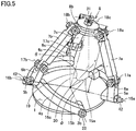
Fig. 5 is a perspective view illustrating a state in which the posture of a distal end member is changed in the parallel link mechanism illustrated inFig. 1 . -
Fig. 6 is a cross-sectional view of the parallel link mechanism according to a second embodiment. -
Fig. 7 is a cross-sectional view in line VII-VII inFig. 6 . -
Fig. 8 is a perspective view of a link actuation device according to a third embodiment. -
Fig. 9 is a cross-sectional view of the link actuation device illustrated inFig. 8 . -
Fig. 10 is a perspective view illustrating the link actuation device according to a fourth embodiment. -
Fig. 11 is a perspective view illustrating the link actuation device according to a fifth embodiment. -
Fig. 12 is a perspective view illustrating a configuration of the parallel link mechanism according to a sixth embodiment. -
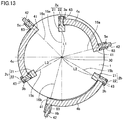
Fig. 13 is a cross-sectional view of the parallel link mechanism illustrated inFig. 12 . -
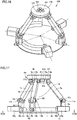
Fig. 14 is a perspective view illustrating a configuration of the parallel link mechanism according to a seventh embodiment. -
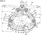
Fig. 15 is a perspective view illustrating the link actuation device according to an eighth embodiment in a state before a working body attachment member is mounted. -
Fig. 16 is a perspective view illustrating the link actuation device according the eighth embodiment in a state in which the working body attachment member is mounted. -
Fig. 17 is a front view of the link actuation device illustrated inFig. 16 . -
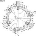
Fig. 18 is a cross-sectional view in line XVIII-XVIII inFig. 17 . -
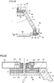
Fig. 19 is a cross-sectional view in line XIX-XIX inFig. 18 . -
Fig. 20 is an enlarged cross-sectional view illustrating the configuration of a region XX surrounded by a dotted line inFig. 19 in more detail. -
Fig. 21 is a perspective view illustrating a state in which the posture of the distal end member is changed in the link actuation device illustrated inFig. 15 . -
Fig. 22 is a perspective view illustrating a manner in which a working body is attached to the working body attachment member of the link actuation device inFig. 16 . -
Fig. 23 is a front view illustrating a use example of the link actuation device in the eighth embodiment illustrated inFig. 22 . -
Fig. 24 is a perspective view illustrating the link actuation device according a ninth embodiment in a state in which the working body attachment member is mounted. -
Fig. 25 is a front view illustrating a use example of the link actuation device in the ninth embodiment illustrated inFig. 24 . -
Fig. 26 is a perspective view illustrating the link actuation device according a tenth embodiment in a state in which the working body attachment member is mounted. -
Fig. 27 is a front view illustrating a use example of the link actuation device in the tenth embodiment illustrated inFig. 26 , -
Fig. 28 is a diagram illustrating an overall configuration of the link actuation device according to an eleventh embodiment. -
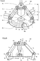
Fig. 29 is a perspective view illustrating a configuration of the parallel link mechanism according to the eleventh embodiment. -
Fig. 30 is a front view of the parallel link mechanism illustrated inFig. 29 . -
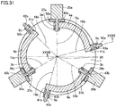
Fig. 31 is a cross-sectional view in line XXXI-XXXI inFig. 30 . -
Fig. 32 is a cross-sectional view in line XXXII-XXXII inFig. 31 . -
Fig. 33 is a perspective view illustrating a state in which the posture of the distal end member is changed in the parallel link mechanism illustrated inFig. 29 . -
Fig. 34 is a graph illustrating the torque of motors when interference occurs during operation (in a case of a collision). -
Fig. 35 is a diagram for explaining an example in which control is performed by detecting disturbance in torque when interference occurs at the distal end member of the link actuation device. -
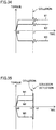
Fig. 36 is a diagram illustrating an example of a database of torque acting on motors that is provided in a control device. -
Fig. 37 is a diagram illustrating a first working example to which load estimation is applied. -
Fig. 38 is a flowchart illustrating a method of measuring and estimating a load exerted on a working body by calculation. -
Fig. 39 is a flowchart illustrating a method of measuring and estimating a load exerted on a working body using a table. -
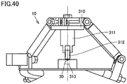
Fig. 40 is a diagram illustrating a second working example to which load estimation is applied. -
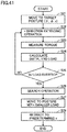
Fig. 41 is a flowchart for explaining a pin pushing operation. - Embodiments of the present invention will be described below with reference to the drawings. Like or corresponding parts in the drawings are denoted by like reference numerals and a description thereof is not repeated.
-
Fig. 1 is a perspective view illustrating a configuration of a parallel link mechanism according to a first embodiment of the present invention.Fig. 2 is a front view of the parallel link mechanism illustrated inFig. 1 .Fig. 3 is a cross-sectional view in line III-III inFig. 2 .Fig. 4 is a cross-sectional view in line IV-IV inFig. 3 . - A
parallel link mechanism 10 illustrated inFig. 1 to Fig. 4 includes aproximal end member 1, adistal end member 8, and threelink mechanisms 11.Proximal end member 1 is a plate-shaped body having a circular shape in two dimensions.Proximal end member 1 may have any shape. For example, the two-dimensional shape ofproximal end member 1 may be polygonal such as quadrangular and triangular, or oval or semi-circular. The number oflink mechanisms 11 is three or more, for example, may be four or five. - Three
link mechanisms 11 connectproximal end member 1 todistal end member 8 such that a posture ofdistal end member 8 relative toproximal end member 1 can be changed. Threelink mechanisms 11 include respectivefirst link members second link members third link members fourth link members First link members proximal end member 1 at a first revolute pair unit. Specifically, proximal-end connecting portions proximal end member 1. Proximal-end connecting portions base portion 21 fixed to a surface ofproximal end member 1 and ashaft portion 22 formed to protrude frombase portion 21 toward the outer periphery.Shaft portion 22 is inserted into a throughhole 43 in a corresponding one offirst link members Nuts shaft portions 22 protruding from throughholes 43 offirst link members First link members shaft portion 22.Shaft portion 22 and a portion of the corresponding one offirst link members hole 43 receiving thisshaft portion 22 constitute the first revolute pair unit. -
First link members hole 43 is formed at a first end of each offirst link members Fig. 3 , in a two-dimensional view as viewed from a direction vertical to the surface ofproximal end member 1, the inner peripheral-side surfaces offirst link members proximal end member 1. The radius of curvature of the inner peripheral-side surface may be the same as the radius of curvature of the outer periphery ofproximal end member 1 or may be larger than the radius of curvature of the outer periphery. The shape offirst link members
For example, the shape offirst link members Fig. 3 ,first link members proximal end member 1. - In each of
first link members shaft portion 42 is formed at asecond end 41 positioned on the opposite side to the first end having throughhole 43.Shaft portion 42 is formed to extend from the outer periphery ofproximal end member 1 toward the outside.Shaft portion 42 is formed on the outer peripheral side surface on the opposite side to the inner peripheral side surface facingproximal end member 1 in each offirst link members Shaft portion 42 is inserted in a throughhole 63 of the corresponding one ofsecond link members Nuts shaft portions 42 protruding from throughholes 63 ofsecond link members Second link members shaft portion 42.Shaft portion 42 and a portion of the corresponding one ofsecond link members hole 63 receiving thisshaft portion 42 constitute a second revolute pair unit. That is,second link members first link members - Each of
center axes shaft portions 22 in proximal-end connecting portions center axes shaft portions 42 at second ends 41 offirst link members Fig. 1 andFig. 3 , center axes 15a, 15b, and 15c ofshaft portions 22 andcenter axes shaft portions 42 intersect at a sphericallink center point 30. This intersection is a necessary condition, and the arrangement of the first and second revolute pair units can be changed as desired if center axes 15a, 15b, and 15c of the first revolute pair units andcenter axes link center point 30. -
Second link members hole 63 is formed at a first end of each ofsecond link members second link members second link members Fig. 1 andFig. 3 , in a state in whichfirst link members proximal end member 1,second link members proximal end member 1.Second link members proximal end member 1 or may be arranged inside of the outer periphery ofproximal end member 1. - In each of
second link members third link members hole 63. At the second end of each ofsecond link members third link members second link members hole 73 at the first end of the corresponding one ofthird link members members second link members hole 73 at the first end of the corresponding one ofthird link members members second link members third link members members member second link member third link member second link members third link members - Each of
center axes coupling members Center axes axes -
Third link members hole 73 is formed at the first end of each ofthird link members third link members third link members - In each of
third link members hole 74 is formed at a second end positioned on the opposite side to the first end having throughhole 73. In each offourth link members third link members wall portion 83 facing the depressed portion of each offourth link members hole 74 at the second end of each ofthird link members wall portion 83 of the corresponding one offourth link members members hole 74 at the second end of the corresponding one ofthird link members wall portion 83 of the corresponding one offourth link members members third link members fourth link members members member third link member wall portion 83 offourth link member third link members fourth link members - Each of
center axes coupling members Center axes center axes -
Fourth link members base portions 81a to 81c each connected to wallportion 83. The two-dimensional shape ofbase portions 81a to 81c is circular. As illustrated inFig. 4 , acenter shaft 82 is provided at the middle ofbase portion 81a.Base portion 81b offourth link member 8b is arranged so as to overlapbase portion 81a. A through hole is formed at the middle ofbase portion 81b.Base portion 81c offourth link member 8c is arranged so as to lie onbase portion 81b. A through hole is formed at the middle ofbase portion 81c.Base portions base portion 81a withcenter shaft 82 inserted in their respective through holes. Anut 9 is installed as a fastening member at the tip end portion ofcenter shaft 82.Fourth link members shaft 82. Inparallel link mechanism 10 illustrated inFig. 1 to Fig. 4 ,center shaft 82 of the stackedfourth link members base portions 81a to 81c can be considered asdistal end member 8. As a distal end member, another member may be connected to centershaft 82 or one ofbase portions 81a to 81c. In the configuration as described above, each ofbase portions 81a to 81c,center shaft 82, andnut 9 constitute a fifth revolute pair unit. As can be understood fromFig. 1 , fifth center axes 19 of the fifth revolute pair units of threelink mechanisms 11 are arranged to overlap each other. That is, the fifth revolute pair units of a plurality oflink mechanisms 11 are arranged to overlap each other at one place. A bolt that is a member separate frombase 81a may be used ascenter shaft 82. In this case, a through hole receiving the bolt is formed at the middle portion ofbase portion 81a. - In
fourth link members - As illustrated in
Fig. 1 andFig. 3 ,first center axes link center point 30. As illustrated inFig. 4 , fifth center axes 19 of the respective fifth revolute pair units of thelink mechanisms 11 overlap each other and intersect with sphericallink center point 30. As long as the relation above is satisfied, the arrangement of the pair units can be set as desired. -
Fig. 5 is a perspective view illustrating a state in which the posture of the distal end member is changed in the parallel link mechanism illustrated inFig. 1 . As illustrated inFig. 5 , the position ofdistal end member 8 can be changed as desired by changing the respective angles of rotation aroundfirst center axes first link members Fig. 5 , the angle of rotation aroundfirst center axis 15b offirst link member 4b is relatively increased so that thefourth link member 8b side indistal end member 8 is lifted upward, and the entiredistal end member 8 moves to the opposite side to the side on whichfourth link member 8b is positioned, as viewed from a distalend member center 31. - In the
parallel link mechanism 10 illustrated inFig. 1 to Fig. 5 , because of the configuration as described above,distal end member 8 operates on a sphere around sphericallink center point 30. That is, as illustrated inFig. 5 , the posture ofdistal end member 8 can be represented by three-dimensional polar coordinates (r, θ, ϕ) in which sphericallink center point 30 is the origin. As used herein the bend angle θ is the angle formed by: a straight line passing through sphericallink center point 30 and a point at which a line extending downward vertically from distalend member center 31 intersects a plane includingfirst center axes proximal end member 1 andfirst link members fifth center axis 19 that is the distal end member center axis. The turning angle ϕ is the angle formed by: a straight line passing through sphericallink center point 30 and a point at which a line extending downward vertically from distalend member center 31 intersects a plane includingfirst center axes first center axis 15a of the first revolute pair unit offirst link mechanism 11. The center-to-center distance r is the distance between sphericallink center point 30 and distalend member center 31. -
Parallel link mechanism 10 according to the present disclosure includesproximal end member 1 and three ormore link mechanisms 11. Three ormore link mechanisms 11 connectproximal end member 1 todistal end member 8. Three ormore link mechanisms 11 can change the posture ofdistal end member 8 relative toproximal end member 1. Three ormore link mechanisms 11 each include first to fourth link members.First link members proximal end member 1 at the first revolute pair units.Second link members first link members Third link members second link members Fourth link members third link members Fourth link members distal end member 8 at the fifth revolute pair units. In three ormore link mechanisms 11,first center axes link center point 30. Fifth center axes 19 of the respective fifth revolute pair units in three ormore link mechanisms 11 overlap each other and intersect with sphericallink center point 30. - In this manner, since each of three or
more link mechanisms 11 is a five-bar chain structure having first to fifth revolute pair units,distal end member 8 can be moved relative toproximal end member 1 with, in total, three degrees of freedom including two degrees of freedom of rotation around sphericallink center point 30 and one degree of freedom in a direction alongfifth center axis 19. Therefore,distal end member 8 can be moved relative toproximal end member 1 along a sphere around sphericallink center point 30 and also can be moved in a direction alongfifth center axis 19 independently of the movement along the sphere. As a result,distal end member 8 can be moved along the sphere, and the radius of the sphere along whichdistal end member 8 moves can be adjusted, so that the operable range ofdistal end member 8 can be increased compared with whendistal end member 8 can move only along a sphere with a fixed radius. As used herein "fourth link members distal end member 8 at the fifth revolute pair units" means thatfourth link members fourth link members - In
parallel link mechanism 10 described above,third center axis fourth center axis second center axis third center axis third link member fourth center axis link mechanism 11 are parallel to each other, the configuration ofthird link member - In
parallel link mechanism 10 described above,third center axis fourth center axis second center axis parallel link mechanism 10, the workability in assembly work can be improved in the step of connectingsecond link members first link members second link members third link members - In
parallel link mechanism 10 described above, whenproximal end member 1 is viewed two-dimensionally fromdistal end member 8, the second revolute pair units may be positioned outside of the outer periphery ofproximal end member 1. In this case, the influence ofproximal end member 1 on the operable range of the second revolute pair units can be reduced, compared with when the second revolute pair units are positioned inside of the outer periphery ofproximal end member 1. For example, when viewed from the lateral direction along a first surface on thedistal end member 8 side ofproximal end member 1, the operable range of the second revolute pair units can be expanded to a second surface side on the opposite side to the first surface ofproximal end member 1. Here, it is preferable thatfirst link members proximal end member 1. -
Fig. 6 is a cross-sectional view of the parallel link mechanism according to a second embodiment.Fig. 7 is a cross-sectional view in line VII-VII inFig. 6. Fig. 6 corresponds toFig. 3 , andFig. 7 corresponds toFig. 4 . - The parallel link mechanism illustrated in
Fig. 6 and Fig. 7 basically includes a configuration similar toparallel link mechanism 10 illustrated inFig. 1 to Fig. 5 but differs from the parallel link mechanism illustrated inFig. 1 to Fig. 5 in thatbearings 25 to 29 as rotation resistance reducing means are respectively provided in the first to fifth revolute pair units. InFig. 6 and Fig. 7 ,bearings 25 to 29 are installed in all of the revolute pair units. However, a bearing may be installed in at least one of the first to fifth revolute pair units. - Specifically, as illustrated in
Fig. 6 , in the first revolute pair unit, bearing 25 is arranged betweenshaft portion 22 of each of proximal-end connecting portion first link member first link member shaft portion 22 may be fixed so as to be sandwiched betweennut base portion 21. - In the second revolute pair unit, bearing 26 is arranged between
shaft portion 42 of each offirst link member second link members second link member shaft portion 42 may be fixed so as to be sandwiched betweennut first link member - In the third revolute pair unit, as illustrated in
Fig. 7 , bearing 27 is arranged between each ofcoupling members Fig. 2 ) and the corresponding one ofthird link members Fig. 2 ). For example, the outer race of bearing 27 may be fixed tothird link member third link member third link member coupling member coupling member second link member third link member second link member second link member coupling member - In the fourth revolute pair unit, as illustrated in
Fig. 7 , bearing 28 is arranged between each ofcoupling members Fig. 2 ) and the corresponding one ofthird link members Fig. 2 ). For example, the outer race of bearing 28 may be fixed tothird link member coupling member - In the fifth revolute pair unit, bearing 29 is arranged between
center shaft 82 and each ofbase members base member shaft portion 82 may be fixed so as to be sandwiched betweennut 9 andbase member 81a. InFig. 6 and Fig. 7 ,bearings 25 to 29 are used as rotation resistance reducing means. However, a member different from a bearing may be applied as long as rotation resistance can be reduced. - In the parallel link mechanism described above, at least one of the first to fifth revolute pair units may include
bearings 25 to 29. In this case, the operation of the revolute pair units equipped withbearings 25 to 29 can be made smooth, and the accuracy in positioning thedistal end member 8 can be improved. The installation ofbearings 25 to 29 reduces friction torque of the revolute pair units equipped with the bearings, thereby suppressing heat generation at the revolute pair units and, consequently, prolonging the life of the revolute pair units. Furthermore, the installation ofbearings 25 to 29 can suppress rattling during operation of the revolute pair units, compared with whenbearings 25 to 29 are not used. -
Fig. 8 is a perspective view of the link actuation device according to a third embodiment.Fig. 9 is a cross-sectional view of the link actuation device illustrated inFig. 8. Fig. 8 corresponds toFig. 1 , andFig. 9 corresponds toFig. 3 . - The link actuation device illustrated in
Fig. 8 andFig. 9 includesparallel link mechanism 10 illustrated inFig. 1 to Fig. 5 and posturecontrol drive sources control drive sources link mechanisms 11. Posturecontrol drive sources distal end member 8 relative toproximal end member 1 as desired by changing the respective angles of rotation aroundfirst center axes first link members - As illustrated in
Fig. 8 andFig. 9 , posturecontrol drive sources parts proximal end member 1. Fixingparts proximal end member 1. Fixingparts - Posture
control drive sources control drive sources rotatable rotation shafts 37.Rotation shafts 37 are inserted in throughholes 43 offirst link members first link members respective rotation shafts 37. Rotation ofrotation shafts 37 causesfirst link members first center axes Fig. 9 ,first center axes rotation shaft 37. - Posture
control drive sources first center axes control drive sources distal end member 8 side ofproximal end member 1 so as to protrude outward from the outer periphery ofproximal end member 1. - With such a configuration, the posture of
distal end member 8 relative toproximal end member 1 can be uniquely determined by the state of each link mechanism 11 (seeFig. 1 ). That is, the posture ofdistal end member 8 can be controlled by controlling the respective postures offirst link members proximal end member 1 or the respective angles of rotation offirst link members first center axes - When three or more link mechanisms 11 (see
Fig. 1 ) are installed in the link actuation device, posturecontrol drive sources more link mechanisms 11. - The link actuation device according to the present disclosure includes
parallel link mechanism 10 described above and posturecontrol drive sources control drive sources link mechanisms 11 among three ormore link mechanisms 11 and change the posture ofdistal end member 8 relative toproximal end member 1 as desired. - In this case, at least three posture
control drive sources link mechanisms 11 thereby allowingdistal end member 8 to operate in a wide range and precisely.Parallel link mechanism 10 as described above can be used to provide a lightweight and compact link actuation device. -
Fig. 10 is a perspective view illustrating the link actuation device according to a fourth embodiment. The link actuation device illustrated inFig. 10 basically includes a configuration similar to the link actuation device illustrated inFig. 8 andFig. 9 but differs from the link actuation device illustrated inFig. 8 andFig. 9 in arrangement of posturecontrol drive sources Fig. 10 , posturecontrol drive sources proximal end member 1, on the surface on thedistal end member 8 side ofproximal end member 1. Fixingparts control drive sources proximal end member 1 on the inner peripheral side offirst link members control drive sources parts - Such a configuration can achieve an effect similar to that of the link actuation device illustrated in
Fig. 8 andFig. 9 . In addition, since posturecontrol drive sources proximal end member 1, the area occupied by the device can be reduced compared with the link actuation device illustrated inFig. 8 andFig. 9 . -
Fig. 11 is a perspective view illustrating the link actuation device according to a fifth embodiment. The link actuation device illustrated inFig. 11 basically has a configuration similar to the link actuation device illustrated inFig. 10 but differs from the link actuation device illustrated inFig. 10 in the arrangement of posturecontrol drive sources control drive sources first link members Fig. 11 , posturecontrol drive sources proximal end member 1. That is, posturecontrol drive sources distal end member 8 inproximal end member 1. The method of fixing posturecontrol drive sources proximal end member 1 is basically similar to the one in the link actuation device illustrated inFig. 10 . Posture control drivesource 35a is described as an example. Posture control drivesource 35a is connected to fixingpart 36a fixed to the back surface ofproximal end member 1. Agear 38 is fixed torotation shaft 37 of each of posturecontrol drive sources gear 39 is installed to be meshed withgear 38.Gear 39 is rotatably installed onshaft portion 22 of each of proximal-end connecting portions proximal end member 1.Gear 39 is fixed to each offirst link members rotation shafts 37 of posturecontrol drive sources first link members first center axes gears - Such a configuration can achieve an effect similar to that of the link actuation device illustrated in
Fig. 8 andFig. 9 . In addition, since posturecontrol drive sources proximal end member 1, interference of posturecontrol drive sources Fig. 1 ) can be prevented. Furthermore, since posturecontrol drive sources proximal end member 1 in a two-dimensional view, the area occupied by the device can be reduced, compared with the link actuation device illustrated inFig. 8 andFig. 9 . -
Fig. 12 is a perspective view illustrating a configuration of the parallel link mechanism according to a sixth embodiment.Fig. 13 is a cross-sectional view of the parallel link mechanism illustrated inFig. 12. Fig. 12 corresponds toFig. 1 , andFig. 13 corresponds toFig. 3 . The parallel link mechanism illustrated inFig. 12 andFig. 13 basically has a configuration similar to the parallel link mechanism illustrated inFig. 1 to Fig. 5 but, as illustrated inFig. 13 , differs in that the respective distances L1 to L3 from proximal-end connecting portions end connecting portion 2a to sphericallink center point 30 is the smallest. Distance L2 from proximal-end connecting portion 2b to sphericallink center point 30 is larger than the above distance L1. Distance L3 from proximal-end connecting portion 2c to sphericallink center point 30 is larger than the above distance L1 and smaller than distance L2. In a two-dimensional view illustrated inFig. 13 ,first link member 4a is arranged at a position overlapping the surface ofproximal end member 1. Anotherfirst link member 4b is arranged outside of the outer periphery on the surface ofproximal end member 1. The otherfirst link member 4c is arranged such that its outer peripheral portion substantially overlaps the outer peripheral portion of the surface ofproximal end member 1 in a two-dimensional view. - In this way, even when respective distances L1 to L3 from proximal-
end connecting portions Fig. 1 to Fig. 5 can be achieved. That is, as long as the following conditions are met:first center axes link center point 30, and fifth center axes 19 (seeFig. 2 ) of the respective fifth revolute pair units in three link mechanisms 11 (seeFig. 1 ) overlap each other and intersect with sphericallink center point 30,distal end member 8 can be moved relative toproximal end member 1 along a sphere around sphericallink center point 30 and can be moved also in a direction along fifth center axes 19 independently of the movement along the sphere, in the same manner as the parallel link mechanism illustrated inFig. 1 to Fig. 5 . -
Fig. 14 is a perspective view illustrating a configuration of the parallel link mechanism according to a seventh embodiment. The parallel link mechanism illustrated inFig. 14 basically has a configuration similar to the parallel link mechanism illustrated inFig. 1 to Fig. 5 but differs in the configuration ofproximal end member 1 and the relative arrangement between proximal-end connecting portions first link members parallel link mechanism 10 illustrated inFig. 14 , anopening 45 is formed inproximal end member 1. Whenproximal end member 1 is two-dimensionally viewed fromdistal end member 8, the first revolute pair units and the second revolute pair units are positioned in the inside ofopening 45. Proximal-end connecting portions proximal end member 1 and arranged on the outer peripheral side offirst link members - With the configuration as described above,
proximal end member 1 is not present at a position overlapping the second revolute pair units in a two-dimensional view. Therefore, when viewed from the lateral direction along a first surface on thedistal end member 8 side ofproximal end member 1, the operable range of the second revolute pair units can be expanded to a second surface side (back surface side) on the opposite side to the first surface ofproximal end member 1. As a result, thedistal end member 8 can be moved to a position near sphericallink center point 30. - Posture
control drive sources Fig. 8 to Fig. 11 may be applied to the parallel link mechanism in each embodiment described above to configure a link actuation device. Although the number oflink mechanisms 11 is three in each embodiment, the number oflink mechanisms 11 may be any number equal to or greater than four, for example, five, six, or eight. -
Fig. 15 is a perspective view illustrating a link actuation device according to an eighth embodiment in a state before a working body attachment member is mounted.Fig. 16 is a perspective view illustrating the link actuation device according to the eighth embodiment in a state in which the working body attachment member is mounted.Fig. 17 is a front view of the link actuation device illustrated inFig. 16 .Fig. 18 is a cross-sectional view in line XVIII-XVIII inFig. 17 .Fig. 19 is a cross-sectional view in line XIX-XIX inFig. 18 .Fig. 20 is an enlarged cross-sectional view illustrating the configuration of a region XX surrounded by a dotted line inFig. 19 in more detail. - A
link actuation device 10A illustrated inFig. 15 to Fig. 20 includesproximal end member 1,distal end member 8, and threelink mechanisms 11.Proximal end member 1 is a plate-shaped body having a circular shape in two dimensions.Proximal end member 1 may have any shape. For example, the two-dimensional shape ofproximal end member 1 may be polygonal such as quadrangular and triangular, or oval or semi-circular. The number oflink mechanisms 11 is three or more, for example, may be four or five. - Three
link mechanisms 11 connectproximal end member 1 todistal end member 8 such that a posture ofdistal end member 8 relative toproximal end member 1 can be changed. Threelink mechanisms 11 include respectivefirst link members second link members third link members fourth link members First link members proximal end member 1 so as to be rotatable by posturecontrol drive sources control drive sources -
First link members hole 43 is formed at a first end of each offirst link members Fig. 18 , in a two-dimensional view as viewed from a direction vertical to the surface ofproximal end member 1, the inner peripheral-side surfaces offirst link members proximal end member 1. The radius of curvature of the inner peripheral-side surface may be the same as the radius of curvature of the outer periphery ofproximal end member 1 or may be larger than the radius of curvature of the outer periphery. The shape offirst link members
For example, the shape offirst link members Fig. 18 ,first link members proximal end member 1. However,first link members proximal end member 1. - In each of
first link members shaft portion 42 is formed at asecond end 41 positioned on the opposite side to the first end having throughhole 43.Shaft portion 42 is formed to extend from the outer periphery ofproximal end member 1 toward the outside.Shaft portion 42 is formed on the outer peripheral side surface on the opposite side to the inner peripheral side surface facingproximal end member 1 in each offirst link members Shaft portion 42 is inserted in throughhole 63 of the corresponding one ofsecond link members Nuts shaft portions 42 protruding from throughholes 63 ofsecond link members Second link members shaft portion 42.Shaft portion 42 and a portion of the corresponding one ofsecond link members hole 63 receiving thisshaft portion 42 constitute a second revolute pair unit R2. That is,second link members first link members - Each of
center axes center axes shaft portions 42 at second ends 41 offirst link members Fig. 15 andFig. 18 , center axes 15a, 15b, and 15c ofrotation shafts 37 described later andcenter axes shaft portions 42 intersect at sphericallink center point 30. This intersection is a necessary condition, and the arrangement of first revolute pair units R1 and second revolute pair units R2 can be changed as desired if center axes 15a, 15b, and 15c of first revolute pair units R1 andcenter axes link center point 30. -
Second link members hole 63 is formed at a first end of each ofsecond link members second link members second link members Fig. 15 andFig. 18 , when viewed fromdistal end member 8 in a state in whichfirst link members proximal end member 1,second link members proximal end member 1.Second link members proximal end member 1.Second link members proximal end member 1. - In each of
second link members third link members hole 63. At the second end of each ofsecond link members third link members second link member hole 73 at the first end of the corresponding one ofthird link member members second link members hole 73 at the first end of the corresponding one ofthird link members members second link members third link members members member second link member third link member second link members third link members - Each of
center axes coupling members Center axes axes -
Second link members center axes first link members 4a to 4c and the structure ofsecond link members 6a to 6c are slightly different from those described above. Specifically, in such a manner, a through hole is formed at an end (the location of revolute pair unit R2) of each offirst link members 4a to 4c, and the location corresponding to revolute pair unit R2 in each ofsecond link members 6a to 6c is formed in the shape of a shaft. In revolute pair unit R2, the shaft-shaped portion of each ofsecond link members 6a to 6c is inserted in the through hole of the corresponding one offirst link members 4a to 4c. In each ofsecond link members 6a to 6c, the shaft-shaped portion at revolute pair unit R2 extends like a rod and its end portion serve as a depressed portion for connecting the corresponding one ofthird link members 7a to 7c. That is, for example, a triangle formed by three points: sphericallink center point 30, revolute pair unit R3, and revolute pair unit R4, is a geometric structure that rotates on revolute pair unit R2. Three revolute pair units R2, R3, and R4 are arranged to have such a configuration. -
Third link members hole 73 is formed at a first end of each ofthird link members third link members third link members - In each of
third link members hole 74 is formed at a second end positioned on the opposite side to the first end having throughhole 73. In each offourth link members third link members wall portion 83 facing the depressed portion of each offourth link members hole 74 at the second end of each ofthird link members wall portion 83 of the corresponding one offourth link members members hole 74 at the second end of the corresponding one ofthird link members wall portion 83 of the corresponding one offourth link members members third link members fourth link members members member third link member wall portion 83 offourth link member third link members fourth link members - Each of
center axes coupling members Center axes center axes -
Fourth link members respective base members 81a to 81c each connected to wallportion 83. Therefore,fourth link member 8a includesbase member 81a andwall portion 83 coupled tothird link member 7a.Fourth link member 8b is formed withbase member 81b andwall portion 83 coupled tothird link member 7b.Fourth link member 8c is formed withbase member 81c andwall portion 83 coupled tothird link member 7c. - The two-dimensional shape of
base members 81a to 81c is circular. At the middle ofbase member 81a, as illustrated inFig. 19 ,center shaft 82 is provided. Therefore,fourth link member 8a includescenter shaft 82, in addition tobase member 81a andwall portion 83.Base member 81b offourth link member 8b is arranged so as to overlapbase member 81a. A through hole is formed at the middle ofbase member 81b.Base member 81c offourth link member 8c is arranged so as to lie onbase member 81b. A through hole is formed at the middle ofbase member 81c.
Base members base member 81a withcenter shaft 82 inserted in their respective through holes. Anut 9 is installed as a fastening member at the tip end portion of thecenter shaft 82.Fourth link members shaft 82. In the parallel link mechanism illustrated inFig. 15 to Fig. 20 ,center shaft 82 of the stackedfourth link members base members 81a to 81c can be considered asdistal end member 8. As a distal end member, another member may be connected to centershaft 82 or one ofbase members 81a to 81c. In the configuration as described above, each ofbase members 81a to 81c,center shaft 82, andnut 9 constitute a fifth revolute pair unit R5. As can be understood fromFig. 19 , fifth center axes 19 of fifth revolute pair units R5 of threelink mechanisms 11 are arranged to overlap each other. That is, fifth revolute pair units R5 of a plurality oflink mechanisms 11 are arranged to overlap each other at one place. A bolt that is a member separate frombase member 81a may be used ascenter shaft 82. In this case, a through hole receiving the bolt is formed at the middle portion ofbase member 81a. - In
fourth link members - As illustrated in
Fig. 15 andFig. 18 ,first center axes link center point 30. As illustrated inFig. 19 , fifth center axes 19 of respective fifth revolute pair units R5 of thelink mechanisms 11 overlap each other and intersect with sphericallink center point 30. As long as the relation above is satisfied, the arrangement of the pair units R1 to R5 can be set as desired. - Referring to
Fig. 15 to Fig. 18 ,link actuation device 10A includes the parallel link mechanism having the configuration described above and posturecontrol drive sources control drive sources link mechanisms 11. Posturecontrol drive sources distal end member 8 relative toproximal end member 1 as desired by changing the respective angles of rotation aroundfirst center axes first link members Fig. 19 , posturecontrol drive sources - As illustrated in
Fig. 15 andFig. 18 , posturecontrol drive sources parts proximal end member 1. Fixingparts proximal end member 1. Fixingparts - Posture
control drive sources control drive sources rotatable rotation shafts 37.Rotation shafts 37 are inserted in throughholes 43 offirst link members first link members rotation shafts 37. Rotation ofrotation shafts 37 causesfirst link members first center axes Fig. 18 ,first center axes rotation shaft 37.Rotation shaft 37 and a portion of the corresponding one offirst link members hole 43 receiving thisrotation shaft 37 constitute first revolute pair unit R1. - Posture
control drive sources first center axes control drive sources distal end member 8 side ofproximal end member 1 so as to protrude outward from the outer periphery ofproximal end member 1. - With such a configuration, the posture of
distal end member 8 relative toproximal end member 1 can be uniquely determined by the state of each link mechanism 11 (seeFig. 15 ). That is, the posture ofdistal end member 8 can be controlled by controlling the respective postures offirst link members proximal end member 1 or the respective angles of rotation offirst link members first center axes - When three or more link mechanisms 11 (see
Fig. 15 ) are installed in the link actuation device, posturecontrol drive sources more link mechanisms 11. - As illustrated in
FIGs. 16, 17 ,19, and 20 , a workingbody attachment member 121 is fixed to linkactuation device 10A. A working body described later can be attached to workingbody attachment member 121. The working body is a member that performs the working to be performed bylink actuation device 10A. Workingbody attachment member 121 has, for example, a circular shape in a two-dimensional view and has a disc shape having a thickness along the up-down direction inFig. 17 . A throughhole 122 extending in the thickness direction is formed at the middle portion including the center of workingbody attachment member 121 in a two-dimensional view.Center shaft 82 offourth link member 8a andnut 9 are accommodated in throughhole 122. Workingbody attachment member 121 has bolt-accommodatingholes 123. Each bolt-accommodatinghole 123 accommodates abolt 124 as a fastening member so thatbolt 124 fixes workingbody attachment member 121 todistal end member 8. - Working
body attachment member 121 is fixed to any of threefourth link members Fig. 20 , here, as an example, workingbody attachment member 121 is fixed bybolt 124 on the top surface ofbase member 81c, which is the top layer of the stackedbase members hole 123 extends in the thickness direction of workingbody attachment member 121 and penetrates therethrough. Bolt-accommodatinghole 123 may be a through hole through whichbolt 124 can penetrate, but may have a countersunk shape as illustrated inFig. 20 . Alternatively, instead of bolt-accommodatinghole 123, a planar portion for fixing a working body by adhesive may be provided on the surface of workingbody attachment member 121. -
Base member 81c may have ahole 125 having a female thread in which a threaded part ofbolt 124 can be inserted and screwed.Bolt 124 is arranged and screwed so as to be inserted into bolt-accommodatinghole 123 andhole 125 adjacent thereto. Workingbody attachment member 121 is thus fixed tobase member 81c, that is,fourth link member 8c. - On the outside of through
hole 122 in a two-dimensional view,attachment portions 126 each extending in the thickness direction are formed as holes for attaching a working body described later.Attachment portions 126 are spaced apart from throughhole 122.Attachment portions 126 each may be a through hole through which a bolt can penetrate or may have a countersunk shape as illustrated inFig. 20 .Attachment portions 126 may be formed at positions near the outer periphery ofattachment portions 126. Alternatively, instead ofattachment portion 126, a planar portion may be provided on a surface of workingbody attachment member 121 as a space to which a working body is fixed by adhesive. -
Fig. 21 is a perspective view illustrating a state in which the posture of the distal end member is changed in the link actuation device illustrated inFig. 15 . As illustrated inFig. 21 , the position ofdistal end member 8 can be changed as desired by changing each of the angles of rotation aroundfirst center axes first link members Fig. 21 , the angle of rotation aroundfirst center axis 15b offirst link member 4b is relatively increased so that thefourth link member 8b side ofdistal end member 8 is lifted upward, and the entiredistal end member 8 moves to the opposite side to the side on whichfourth link member 8b is positioned as viewed from distalend member center 31. - In
link actuation device 10A illustrated inFig. 15 to Fig. 21 , because of the configuration as described above,distal end member 8 operates on a sphere around sphericallink center point 30. That is, as illustrated inFig. 21 , the posture ofdistal end member 8 can be represented by three-dimensional polar coordinates (r, θ, ϕ) in which sphericallink center point 30 is the origin. As used herein the bend angle θ is the angle formed by: a straight line passing through sphericallink center point 30 and a point at which a line extending downward vertically from distalend member center 31 intersects a plane includingfirst center axes proximal end member 1 andfirst link members fifth center axis 19 that is the distal end member center axis. The turning angle ϕ is the angle formed by: a straight line passing through sphericallink center point 30 and a point at which a line extending downward vertically from distalend member center 31 intersects a plane includingfirst center axes first center axis 15a of first revolute pair unit R1 offirst link mechanism 11. The center-to-center distance r is the distance between sphericallink center point 30 and distalend member center 31. - In
Fig. 21 , for convenience of explanation, the parallel link mechanism that does not have posturecontrol drive sources Fig. 21 ,first link members respective shaft portions 22, which are equivalent to the above-notedrotation shafts 37, connected toproximal end member 1.Nuts respective shaft portions 22. -
Fig. 22 is a perspective view illustrating a manner in which a working body is attached to the working body attachment member of the link actuation device inFig. 16 . As illustrated inFig. 22 , a workingbody 127, which may be called an end effector, is attached to workingbody attachment member 121 oflink actuation device 10A according to the present embodiment. Workingbody 127 is attached by, for example, not-shown bolts accommodated in the above-notedattachment portions 126. InFig. 22 , a shaft protrudes upward from the rectangular parallelepiped-shaped main part of workingbody 127. This shaft serves as, for example, the axis of center of rotation when a drill serving as a working body part is attached to workingbody 127, and the axis for transmitting rotational motive power to the attached drill. However, workingbody 1 27 does not necessarily have such a shaft. -
Fig. 23 is a front view illustrating a use example of the link actuation device in the eighth embodiment illustrated inFig. 22 . As illustrated inFig. 23 , the link actuation device inFig. 22 is turned upside down from the state inFig. 22 , and proximal end member I is fixed to a surface of a ceiling CLG facing downward. Thus, posturecontrol drive sources parts - In
Fig. 23 , workingbody attachment member 121 is attached tobase member 81c as shown inFig. 20 , and workingbody 127 is attached to the opposite side toproximal end member 1, that is, the lower surface inFig. 23 . Workingbody 127 is a hand for gripping an object inFig. 23 . However, the working body is not limited thereto. The hand that is workingbody 127 has a distal end on the lower side split into two parts. Awork target 128 can be pinched and gripped between the two parts. InFig. 23 , the hand that is workingbody 127 grips a connector aswork target 128. However,work target 128 is not limited to a connector. Workingbody 127 is thus installed so that a given work is performed onwork target 128.Work target 128 gripped by workingbody 127 faces aworkbench 129, for example, a connector slot. Workingbody 127 is moved in the up-down direction bylink actuation device 10A. Workingbody 127 thus can insertwork target 128 intoworkbench 129 or removework target 128 fromworkbench 129. InFig. 23 , by changing the distance between sphericallink center point 30 anddistal end member 8,link actuation device 10A can attach and removework target 128 to/fromworkbench 129 oriented in any given direction. -
Link actuation device 10A according to the present disclosure includesproximal end member 1 and three ormore link mechanisms 11. Three ormore link mechanisms 11 are configured to connectproximal end member 1 todistal end member 8. Three ormore link mechanisms 11 can change the posture ofdistal end member 8 relative toproximal end member 1. Three ormore link mechanisms 11 each include first to fourth link members.First link members proximal end member 1 at first revolute pair units R1.Second link members first link members Third link members second link members Fourth link members third link members Fourth link members distal end member 8 at fifth revolute pair units R5. In three ormore link mechanisms 11,first center axes link center point 30. Fifth center axes 19 of respective fifth revolute pair units R5 of three ormore link mechanisms 11 overlap each other and intersect with sphericallink center point 30.Link actuation device 10A further includes posturecontrol drive sources body attachment member 121. Posturecontrol drive sources link mechanisms 11 among three ormore link mechanisms 11 and change the posture ofdistal end member 8 relative toproximal end member 1 as desired. Workingbody attachment member 121 is fixed to any of three or morefourth link members - In this manner, since each of three or
more link mechanisms 11 is a five-bar chain structure having first revolute pair unit R1 to fifth revolute pair unit R5,distal end member 8 can be moved relative toproximal end member 1 with, in total, three degrees of freedom including two degrees of freedom of rotation around sphericallink center point 30 and one degree of freedom in a direction alongfifth center axis 19. Therefore,distal end member 8 can be moved relative toproximal end member 1 along a sphere around sphericallink center point 30 and also can be moved in a direction alongfifth center axis 19 independently of the movement along the sphere. As a result,distal end member 8 can be moved along the sphere, and the radius of the sphere along whichdistal end member 8 moves can be adjusted, so that the operable range ofdistal end member 8 can be increased compared with whendistal end member 8 can move only along a sphere with a fixed radius. As used herein "fourth link members distal end member 8 at fifth revolute pair units R5" means thatfourth link members fourth link members distal end member 8 in a direction alongfifth center axis 19 facilitates an operation such as insertion and removal of a connector to/from a desired place as shown inFig. 23 . - In
link actuation device 10A according to the present disclosure, at least three posturecontrol drive sources link mechanisms 11 thereby allowingdistal end member 8 to operate in a wide range and precisely. The configuration described above can be used to provide a lightweight and compact link actuation device. - Working
body attachment member 121 is fixed to linkactuation device 10A. Thus,link actuation device 10A has workingbody 127 attached to workingbody attachment member 121 and allows the working body to operate stably.Link actuation device 10A therefore can function as a working device capable of working onwork target 128 as a target that is a workpiece. Because of workingbody attachment member 121, even a heavy-weight working body 127 can be fixed to the surface of workingbody attachment member 121 and thus attached more easily than when workingbody attachment member 121 is not provided. Therefore, the heavy-weight working body 127 attached can operate at high speed and high accuracy. Furthermore, the positioning for processing a work target can be performed precisely. -
Fig. 24 is a perspective view illustrating the link actuation device according a ninth embodiment in a state in which the working body attachment member is mounted.Fig. 25 is a front view illustrating a use example of the link actuation device in the ninth embodiment illustrated inFig. 24 . As illustrated inFig. 24 and Fig. 25 , alink actuation device 10B in the present embodiment differs fromlink actuation device 10A in the position where workingbody attachment member 121 and workingbody 127 are arranged. Inlink actuation device 10B inFig. 24 and Fig. 25 ,proximal end member 1 is arranged on the lower side anddistal end member 8 is arranged on the upper side in the same manner as inFig. 15 , and they are not turned upside down unlikeFig. 23 . - As illustrated in
Fig. 25 , workingbody attachment member 121 is fixed to theproximal end member 1 side ofdistal end member 8, that is, the lower side ofdistal end member 8 inFig. 25 . Workingbody 127 is attached to the lower-side surface of workingbody attachment member 121 inFig. 25 . Therefore, workingbody 127 is attached to workingbody attachment member 121 such that its center of gravity is arranged on theproximal end member 1 side with respect todistal end member 8, that is, on the lower side in the figure. Workingbody 127 is arranged such that its position in the height direction is substantially the same asthird link members 7a to 7c. -
Work target 128 that workingbody 127 works on can be arranged on theproximal end member 1 side with respect todistal end member 8. In the present embodiment,work target 128 can be arranged on theproximal end member 1 side with respect todistal end member 8 in the up-down direction inFig. 24 and Fig. 25 . That is,work target 128 is gripped, for example, at the lower region inFig. 25 of workingbody 127 and is arranged betweendistal end member 8 and proximal end memberI. Work target 128 is arranged such that its position in the height direction is substantially the same asfirst link members 4a to 4c.Workbench 129 is illustrated onproximal end member 1. - That is, in
Fig. 24 and Fig. 25 , workingbody attachment member 121, workingbody 127,work target 128, andworkbench 129 are arranged in a position surrounded by three ormore link mechanisms 11 in a two-dimensional view. In other words, workingbody attachment member 121, workingbody 127,work target 128, andworkbench 129 are arranged in a region overlapping withdistal end member 8 in a two-dimensional view, that is, at a middle portion of a region overlapping withproximal end member 1 in a two-dimensional view. -
Fig. 25 illustrates a link actuation device having a configuration different from the originallink actuation device 10B in the present embodiment illustrated inFig. 24 , for convenience of explanation of operation. Specifically, posturecontrol drive sources Fig. 25 . In the link actuation device illustrated inFig. 25 , some members are not illustrated for visibility of the inside operation. Examples of these members includefirst link member 4c andsecond link member 6c. In the link actuation device illustrated inFig. 25 ,first link members proximal end member 1 is viewed fromdistal end member 8. Therefore,first link members 4a to 4c inFig. 25 are lowered more easily to the lower side ofproximal end member 1, that is, to the opposite side todistal end member 8, compared withfirst link members 4a to 4c inFig. 24 . That is, inFig. 25 , workingbody 127 is moved to the lower side more easily inFig. 25 than inFig. 24 . - In
Fig. 25 , workingbody 127 is a hand for gripping an object. However, workingbody 127 is not limited thereto. The hand serving as a gripper that is workingbody 127 has a distal end on the lower side split into two parts.Work target 128 can be pinched and gripped between the two parts. InFig. 25 , the hand that is workingbody 127 grips a pin aswork target 128. However,work target 128 is not limited to a pin.Workbench 129 is placed on the middle portion ofproximal end member 1.Work target 128 gripped by workingbody 127 faces, for example, a pin slot formed inworkbench 129. Workingbody 127 is moved bylink actuation device 10A in the up-down direction alongfifth center axis 19. Workingbody 127 thus can insertwork target 128 into the pin slot inworkbench 129 or removework target 128 fromworkbench 129. It is preferable that, for example, a not-shown load sensor is arranged appropriately and the positioning control of workingbody 127 is performed by referring to output from the load sensor. In this way, workingbody 127 can operate minutely in the state illustrated inFig. 25 to enable minute operation such as inserting and removing a pin into/from the pin slot inworkbench 129 without misalignment. As illustrated inFig. 24 , it is more preferable that the center in a two-dimensional view of workingbody 127 is arranged at a position overlapping sphericallink center point 30. In this manner, the working can be performed more easily. - The present embodiment achieves the following operation and effect in addition to the operation and effect of
link actuation device 10A in the eighth embodiment. Inlink actuation device 10B according to the present disclosure, workingbody 127 performing the working can be attached to workingbody attachment member 121. Workingbody 127 is attached to workingbody attachment member 121 such that the center of gravity of workingbody 127 is arranged on theproximal end member 1 side with respect todistal end member 8. - In this manner, for example, compared with the eighth embodiment in which working
body 127 is attached to workingbody attachment member 121 fixed on the upper surface ofbase member 81c, the distance between the center of gravity of workingbody 127 and sphericallink center point 30 can be reduced. Therefore, compared withlink actuation device 10A in the eighth embodiment, the moment of inertia around sphericallink center point 30 of workingbody 127 can be reduced. In the present embodiment, therefore, vibration of workingbody 127 during positioning operation can be reduced compared with the eighth embodiment. As a result, workingbody 127 in the present embodiment can perform fast and accurate operation. - Supposing that working
body 127 is arranged abovedistal end member 8 outside of the region surrounded by three ormore link mechanisms 1 1 as in the eighth embodiment, the distance between the center of gravity of workingbody 127 and sphericallink center point 30 is greater than the distance in the configuration illustrated inFig. 24 . In the eighth embodiment, therefore, the moment of inertia in the operation of positioning workingbody 127 is larger. The present embodiment can eliminate such inconvenience. -
Link actuation device 10B according to the present disclosure can achieve lower output, that is, energy saving of posturecontrol drive sources 35a to 35c. As a result,link actuation device 10B can be downsized. Such an effect is achieved particularly when, for example, workingbody 127 that is long in the direction offifth center axis 19 or workingbody 127 that has the center of gravity on thedistal end member 8 side is used inFig. 25 . This is because the moment of inertia of workingbody 127 is large particularly when such a workingbody 127 is used. - In the present embodiment, it suffices if working
body 127 is attached to workingbody attachment member 121 such that the center of gravity of workingbody 127 is arranged on theproximal end member 1 side with respect todistal end member 8. That is, as illustrated inFig. 24 and Fig. 25 ,work target 128 andworkbench 129 may be arranged on theproximal end member 1 side of workingbody 127. However, although not illustrated, the arrangement ofwork target 128 andworkbench 129 can be selected as desired as long as the center of gravity of workingbody 127 is arranged on theproximal end member 1 side with respect todistal end member 8. - In
link actuation device 10B, workingbody attachment member 121 is fixed to face theproximal end member 1 side ofdistal end member 8.Work target 128 that workingbody 127 works on can be arranged on theproximal end member 1 side with respect todistal end member 8. In particular, it is preferable thatwork target 128 can be arranged betweendistal end member 8 andproximal end member 1. - As described above, the center of gravity of working
body 127 is arranged on theproximal end member 1 side with respect todistal end member 8. Therefore, even whenwork target 128 is arranged on theproximal end member 1 side with respect todistal end member 8, workingbody 127 can be arranged in a region surrounded by three ormore link mechanisms 11 at a short distance to worktarget 128. Whenwork target 128 can be arranged betweendistal end member 8 andproximal end member 1, in particular, the distance between workingbody 127 andwork target 128 can be reduced so that, for example, the operation such as delivery ofwork target 128 can be performed more reliably. -
Fig. 26 is a perspective view illustrating the link actuation device according a tenth embodiment in a state in which the working body attachment member is mounted.Fig. 27 is a front view illustrating a use example of the link actuation device in the tenth embodiment illustrated inFig. 26 . As illustrated inFig. 26 andFig. 27 , a link actuation device 10C in the present embodiment differs fromlink actuation device 10B in a manner ofproximal end member 1. In link actuation device 10C inFig. 26 andFig. 27 ,proximal end member 1 is arranged on the lower side anddistal end member 8 is arranged on the upper side, similarly to linkactuation device 10B inFig. 24 and Fig. 25 , and they are not turned upside down unlikeFig. 23 . - Specifically, as illustrated in
Fig. 26 ,proximal end member 1 has a proximal end member throughhole 130. Proximal end member throughhole 130 is formed, for example, at the middle portion ofproximal end member 1 so as to have a circular shape around the middle ofproximal end member 1 in a two-dimensional view, that is, the position overlapping sphericallink center point 30. However, proximal end member throughhole 130 is not limited thereto and may have any other two-dimensional shape, for example, a rectangular shape as long as it is formed at the middle portion ofproximal end member 1. - As illustrated in
Fig. 27 , in the present embodiment,work target 128 can be arranged on the opposite side todistal end member 8 relative toproximal end member 1. That is,work target 128 is arranged belowproximal end member 1. Thus, workingbody 127, proximal end member 1 (proximal end member through hole 130), andwork target 128 are arranged in this order from the upper side to the lower side inFig. 27 . Workingbody 127 can work onwork target 128 arranged on the opposite side todistal end member 8 with proximal end member throughhole 130 interposed. That is, in the present embodiment,work target 128 is arranged belowfirst link members 4a to 4c inFig. 27 .Work target 128 is spaced apart fromproximal end member 1 in the direction alongfifth center axis 19. It is preferable thatwork target 128 is mounted onworkbench 129. -
Fig. 27 illustrates a link actuation device having a configuration different from the originallink actuation device 10B in the present embodiment illustrated inFig. 26 , for convenience of explanation of operation, similarly toFig. 24 and Fig. 25 . Specifically, posturecontrol drive sources Fig. 27 . In the link actuation device illustrated inFig. 27 , some members are not illustrated for visibility of the inside operation. Examples of these members includefirst link member 4c andsecond link member 6c. In the link actuation device illustrated inFig. 27 ,first link members proximal end member 1 is viewed fromdistal end member 8. Therefore,first link members 4a to 4c inFig. 27 are lowered more easily to the lower side ofproximal end member 1, that is, to the opposite side todistal end member 8, compared withfirst link members 4a to 4c inFig. 26 . That is, inFig. 27 , workingbody 127 is moved to the lower side inFig. 27 more easily than inFig. 26 . - In
Fig. 27 , workingbody 127 is a dispenser for supplying a coating liquid. An axial protrusion provided at the lowest portion of workingbody 127 is a nozzle for ejecting the liquid. It is preferable that the nozzle extends from the middle portion in a two-dimensional view on the bottom surface of workingbody 127, for example, in a direction alongfifth center axis 19 in such a manner that liquid can be ejected from the lowest portionthereof Work target 128 is a processed member to be coated with a coating liquid ejected by the dispenser of workingbody 127.Work target 128 is placed on, for example, a belt conveyor asworkbench 129. That is,work target 128 is conveyed on the belt conveyor to be arranged, for example, immediately below proximal end member throughhole 130. -
Work target 128 is conveyed to immediately below proximal end member throughhole 130 through the belt conveyor serving asworkbench 129, and the nozzle of workingbody 127 and a region to be coated with liquid on a surface ofwork target 128 are aligned on a straight line through a space in the inside of proximal end member throughhole 130. At this moment, for example, workingbody 127 may be moved by link actuation device 10C in the up-down direction alongfifth center axis 19. The nozzle of workingbody 127 thus can pass through, for example, proximal end member throughhole 130 and move downward therefrom. In this state, workingbody 127 ejects liquid so that a desired place ofwork target 128 is coated with the liquid. It is more preferable that the center of proximal end member I and the center of proximal end member throughhole 130 are arranged at a position overlapping sphericallink center point 30. In this manner, the working can be performed more easily. - The present embodiment achieves the following operation and effect in addition to the operation and effect of
link actuation device 10A in the eighth embodiment andlink actuation device 10B in the ninth embodiment. In link actuation device 10C according to the present disclosure,proximal end member 1 has proximal end member throughhole 1 30.Work target 128 can be arranged on the opposite side todistal end member 8 relative toproximal end member 1. Workingbody 127 can work onwork target 128 arranged on the opposite side todistal end member 8 with proximal end member throughhole 130 interposed. - In this manner, as illustrated in
Fig. 27 , even forwork target 128 located belowproximal end member 1, workingbody 127 can work onwork target 128 because proximal end member throughhole 130 is formed. For example, workingbody 127 is moved by link actuation device 10C in the up-down direction so that workingbody 127 can be arranged in close proximity to worktarget 128. Workingbody 127 thus can perform a desired operation forwork target 128. - In addition to the examples described above, although not illustrated in the figures, when working
body 127 that is long in the axial direction is mounted, workingbody 127 may be passed through proximal end member throughhole 130 and a part of workingbody 127 may protrude belowproximal end member 1 to work onwork target 128. - In the present embodiment, while the moment of inertia of working
body 127 is reduced, similarly to the ninth embodiment, the working can be performed onwork target 128 arranged outside the region surrounded by three ormore link mechanisms 11 of link actuation device 10C. - Although the number of
link mechanisms 11 is three in each embodiment, the number oflink mechanisms 11 may be any number of four or more, for example, five, six, or eight. -
Fig. 28 is a diagram illustrating an overall configuration of the link actuation device according to an eleventh embodiment. Referring toFig. 28 , alink actuation device 200 includesparallel link mechanism 10 on which a working body is mounted, posturecontrol drive sources parallel link mechanism 10, and acontrol device 100 for controlling posturecontrol drive sources First link members parallel link mechanism 10 are attached to the rotation shafts of posturecontrol drive sources - The detail of
parallel link mechanism 10 will be described first and then control of posturecontrol drive sources control device 100 will be described. -
Fig. 29 is a perspective view illustrating a configuration of the parallel link mechanism according to the present eleventh embodiment.Fig. 30 is a front view of the parallel link mechanism illustrated inFig. 29 .Fig. 31 is a cross-sectional view in line XXXI-XXXI inFig. 30 .Fig. 32 is a cross-sectional view in line XXXII-XXXII inFig. 31 . -
Parallel link mechanism 10 illustrated inFig. 29 to Fig. 32 includesproximal end member 1,distal end member 8, and threelink mechanisms 11.Proximal end member 1 is a plate-shaped body having a circular shape in two dimensions.Proximal end member 1 may have any shape. For example, the two-dimensional shape ofproximal end member 1 may be polygonal such as quadrangular and triangular, or oval or semi-circular. The number oflink mechanisms 11 is three or more, for example, may be four or five. - Three
link mechanisms 11 connectproximal end member 1 todistal end member 8 such that a posture ofdistal end member 8 relative toproximal end member 1 can be changed. Threelink mechanisms 11 include respectivefirst link members second link members third link members fourth link members - Posture
control drive sources link mechanisms 11. Posturecontrol drive sources control drive sources distal end member 8 relative toproximal end member 1 as desired by changing the respective angles of rotation aroundfirst center axes first link members -
First link members proximal end member 1 at the first revolute pair units. Specifically, fixingparts proximal end member 1. - Posture
control drive sources parts proximal end member 1. Fixingparts - Posture control drive
source shaft portions Shaft portions parts holes first link members shaft portions holes first link members nuts first link members shaft portions shaft portions first link members first center axes Fig. 31 ,first center axes shaft portions -
Shaft portions first link members holes -
First link members holes first link members Fig. 31 , in a two-dimensional view as viewed from a direction vertical to the surface ofproximal end member 1, the inner peripheral-side surfaces offirst link members first link members first link members - In
first link members shaft portions second ends holes shaft portions proximal end member 1 toward the outside.Shaft portion first link members Shaft portions holes second link members Nuts shaft portions holes Second link members shaft portions Shaft portions second link members holes second link members first link members - Each of
first center axes shaft portions shaft portions second ends first link members Fig. 29 andFig. 31 ,first center axes shaft portions shaft portions link center point 30. This intersection is a necessary condition, and the arrangement of the first and second revolute pair units can be changed as desired iffirst center axes link center point 30. -
Second link members holes second link members second link members second link members - In
second link members third link members holes second link members hole 73a (Fig. 32 ) is also formed at the first end ofthird link member 7a, and not-shown through holes 73b and 73c are formed at similar positions of the respective first ends ofthird link members second link members holes 73a and 73b at the first ends ofthird link members coupling members second link member 6c is arranged to be aligned with through hole 73c at the first end ofthird link member 7c, andcoupling member 13c is inserted. - Coupling
members second link members third link members members members second link members third link members second link members third link members - The respective center axes of
coupling members third center axes -
Second link members third center axes first link members 4a to 4c and the structure ofsecond link members 6a to 6c are slightly different from those described above. Specifically, in such a manner, a through hole is formed at an end (the location of revolute pair unit R2) of each offirst link members 4a to 4c, and the location corresponding to revolute pair unit R2 in each ofsecond link members 6a to 6c is formed in the shape of a shaft. In revolute pair unit R2, the shaft-shaped portion of each ofsecond link members 6a to 6c is inserted in the through hole of the corresponding one offirst link members 4a to 4c. In each ofsecond link members 6a to 6c, the shaft-shaped portion at revolute pair unit R2 extends like a rod and its end portion serves as a depressed portion for connecting the corresponding one ofthird link members 7a to 7c. That is, for example, a triangle formed by three points: sphericallink center point 30, revolute pair unit R3, and revolute pair unit R4, is a geometric structure that rotates on revolute pair unit R2, Three revolute pair units R2, R3, and R4 are arranged to have such a configuration. -
Third link members third link members third link members - In
third link members hole 74a (Fig. 32 ) is formed at a second end positioned on the opposite side to the first end having throughhole 73a. Not-shown through holes 74b and 74c are respectively formed inthird link members hole 74a. - In each of
fourth link members third link members wall portions fourth link members holes 74a, 74b, and 74c at the second ends ofthird link members wall portions fourth link members coupling members - Coupling
members third link members fourth link members members members third link members wall portions fourth link members third link members fourth link members - The respective center axes of
coupling members third center axes -
Fourth link members base portions portions base portions Fig. 32 ,center shaft 82 is provided at the middle ofbase portion 81a,Base portion 81b offourth link member 8b is arranged so as to overlapbase portion 81a. A through hole is formed at the middle ofbase portion 81b.Base portion 81c offourth link member 8c is arranged so as to overlapbase portion 81b. A through hole is formed at the middle ofbase portion 81c.Base portions base portion 81a withcenter shaft 82 inserted in their respective through holes.Nut 9 is installed as a fastening member at the tip end ofcenter shaft 82.Fourth link members shaft 82. Inparallel link mechanism 10 illustrated inFig. 29 to Fig. 32 ,center shaft 82 of the stackedfourth link members base members distal end member 8. As a distal end member, another member may be connected to centershaft 82 or one ofbase portions - In the configuration as described above,
base portions center shaft 82, andnut 9 constitute "fifth revolute pair units". As can be understood fromFig. 29 , fifth center axes 19 as the rotation center axes of the fifth revolute pair units of threelink mechanisms 11 are arranged to overlap each other. That is, the fifth revolute pair units of a plurality oflink mechanisms 11 are arranged to overlap each other at one place. A bolt that is a member separate frombase portion 81a may be used ascenter shaft 82. In this case, a through hole receiving the bolt is formed at the middle portion ofbase portion 81a. - In
fourth link members - As illustrated in
Fig. 29 andFig. 31 ,first center axes link center point 30. As illustrated inFig. 32 , the common fifth center axes 19 of the fifth revolute pair units of thelink mechanisms 11 intersect with sphericallink center point 30, As long as the relation above is satisfied, the arrangement of the pair units can be set as desired. -
Fig. 33 is a perspective view illustrating a state in which the posture of the distal end member is changed in the parallel link mechanism illustrated inFig. 29 . As illustrated inFig. 33 , the position ofdistal end member 8 can be changed as desired by changing the respective angles of rotation aroundfirst center axes first link members Fig. 33 , the angle of rotation aroundfirst center axis 15b offirst link member 4b is relatively increased so that thefourth link member 8b side ofdistal end member 8 is lifted upward, and the entiredistal end member 8 moves to the opposite side to the side on whichfourth link member 8b is positioned as viewed from distalend member center 31. - In
parallel link mechanism 10 illustrated inFig. 29 to Fig. 33 , because of the configuration as described above,distal end member 8 operates on a sphere around sphericallink center point 30. That is, as illustrated inFig. 33 , the posture ofdistal end member 8 can be represented by three-dimensional polar coordinates (θ, ϕ, r) in which sphericallink center point 30 is the origin. As illustrated inFig. 33 , as used herein the bend angle θ is the angle formed by: a straight line passing through sphericallink center point 30 and a point at which a line extending downward vertically from distalend member center 31 intersects a plane includingfirst center axes first link members fifth center axis 19 that is the center axis ofdistal end member 8. The turning angle ϕ is the angle formed by: a straight line passing through sphericallink center point 30 and a point at which a line extending downward vertically from distalend member center 31 intersects a plane includingfirst center axes first center axis 15a of the first revolute pair unit oflink mechanism 11. The center-to-center distance r is the distance between sphericallink center point 30 and distalend member center 31. - In
parallel link mechanism 10 according to the present disclosure, since each of three ormore link mechanisms 11 is a five-bar chain structure having first to fifth revolute pair units,distal end member 8 can be moved relative toproximal end member 1 with, in total, three degrees of freedom including two degrees of freedom of rotation around sphericallink center point 30 and one degree of freedom in a direction alongfifth center axis 19. Therefore,distal end member 8 can be moved relative toproximal end member 1 along a sphere around sphericallink center point 30 and also can be moved in a direction alongfifth center axis 19 independently of the movement along the sphere. As a result,distal end member 8 can be moved along the sphere, and the radius of the sphere along whichdistal end member 8 moves can be adjusted, so that the operable range ofdistal end member 8 can be increased compared with whendistal end member 8 can move only along a sphere with a fixed radius. As used herein "fourth link members distal end member 8 at the fifth revolute pair units" means thatfourth link members fourth link members - Referring to
Fig. 28 again, an overview ofcontrol device 100 that controls the posture control drive sources will be described.Control device 100 includes anexternal command converter 101,individual controllers torque detector 103, and aload detector 104. -
Individual controller 102a includes aposition command converter 111 and acurrent generator 112. Although not illustrated,individual controllers individual controller 102a. -
Individual controllers control drive sources first link members control device 100 in the present eleventh embodiment is characterized in thattorque detector 103 andload detector 104 are provided separately fromindividual controllers - A posture change command for posture
control drive sources external command device 150 sends an operation command (for example, target (θ, ϕ, r)) toexternal command converter 101. Second,external command converter 101 converts the operation command to a position command for each motor and sends the position command to positioncommand converter 111 of each ofindividual controllers position command converter 111 converts the position command to a current command for the motor and sends the current command tocurrent generator 112. Fourth,current generator 112 generates current in proportion to the current command and feeds current to the corresponding posture control drivesource control device 100 measures the current actually flowing and performs feedback control.Current generator 112 has a not-shown current sensor because it is necessary to monitor a current command for the motor and current fed to the motor for feedback control. - When a motor is used as posture
control drive sources distal end member 8 from a certain direction, current generated in each motor increases or decreases in order to keep the posture. The load can be estimated byload detector 104 which calculates the direction and magnitude of torque from a current value of each monitor or a current command value at the moment and estimating the direction and magnitude of the load exerted ondistal end member 8. With the current sensor, torque and load can be estimated by software from the detected current value, and the load can be detected without separately providing a torque sensor or a load sensor. -
External output terminals torque detector 103 andload detector 104 to the outside. Whenexternal output terminals external command device 150 or another external control device. -
Fig. 34 is a graph illustrating the torque of each motor (35a, 35b, 35c) when interference occurs during operation (in a case of a collision). Whendistal end member 8 is driven, each motor gives torque as illustrated at time t0 to t1 inFig. 34 to rotate the link member (4a, 4b, 4c). Torques M1, M2, and M3 in normal operation exhibit a certain value at a low level, but when some interference occurs todistal end member 8 at time t1 during operation, the interference increases or decreases torques M1, M2, and M3 of the motors. -
Fig. 35 is a diagram for explaining an example in which control is performed by detecting disturbance in torque when interference occurs to the distal end member of the link actuation device. InFig. 35 , when disturbance in torques M1, M2, and M3 is detected at time t1, it is assumed that a collision has occurred and at time t2, for example, torques M1, M2, and M3 of the motors are set to zero after time t2 to make emergency stop of the link actuation device. -
Fig. 36 is a diagram illustrating an example of a database of torque acting on each motor that is provided in the control device. In a certain posture of the link actuation device, the torque (T1, T2, T3) of each motor in the direction and magnitude (acting force) of a load exerted on the distal end portion can be determined by calculation. However, preferably, as illustrated inFig. 36 , a database is registered in advance, andcontrol device 100 refers to the database to estimate the direction and magnitude of the load from the torque (T1, T2, T3) at the time when a load is exerted. With this configuration, a load can be estimated faster. -
Fig. 37 is a diagram illustrating a first working example to which load estimation is applied. InFig. 37 , ahand 211 is mounted as a working body onparallel link mechanism 10. Abase member 210 is fixed todistal end member 8, andhand 211 is attached tobase member 210.Hand 211 thus can make a motion similar to that ofdistal end member 8. That is, (θ, ϕ, r) ofhand 211 can be controlled byparallel link mechanism 10.Center shaft 82 is hollow so that a control cable for controlling grip and release ofhand 211 can pass through the inside ofcenter shaft 82 inFig. 32 . In this manner, the first working example is the operation of insertingconnector 212 as a work target into a hole in theworkbench 213 installed obliquely, usinghand 211 attached toparallel link mechanism 10. - A flowchart illustrating control of this operation is shown in
Fig. 38 andFig. 39 .Fig. 38 is a flowchart illustrating a method of measuring and estimating a load exerted on the working body by calculation. - First, at step S1,
control device 100 changes the posture ofparallel link mechanism 10 to take a position immediately before connector insertion, which is the initial target posture represented by three-dimensional polar coordinates (θ, ϕ, r). Whenparallel link mechanism 10 disclosed in the present eleventh embodiment is used, subsequently at step S2, r is operated in the extending direction so thatconnector 212 can be fitted in from a direction along the depth direction of the hole inworkbench 213. - In doing so, at step S3,
control device 100 measures the torque of the motor in operation and estimates the distal end load by calculation at step S4. - If no load is exerted at step S5 (NO at S5),
parallel link mechanism 10 is extended in the r direction until a load is exerted. At a point of time when a load is exerted at step S5 (YES at S5), the operation ofhand 211 is stopped. Then, at step S6, a checking operation is performed. The checking operation is the operation of checking whetherconnector 212 has been inserted into a connector slot inworkbench 213, based on the load during operation (torque). For example, the insertion can be checked with a database including a load (torque) at the time of completion of insertion in a certain operation. If insertion of the connector is confirmed as a result of the checking operation at step S6 (YES at S7), the process ends. If not confirmed (NO at S7), a target position is estimated again based on the direction and magnitude of the load exerted on the distal end at step S8. A series of operation continues to enable insertion of the connector. -
Fig. 39 is a flowchart illustrating a method of measuring and estimating a load exerted on the working body using a table. The flowchart inFig. 39 illustrates the process in which the process at step S4 in the flowchart inFig. 38 is replaced by steps S11 and S12. The process at steps S1 to S3 and S5 to S8 is the same as the one described inFig. 38 and will not be further elaborated. InFig. 39 , at step S11, the load at the distal end portion is estimated by referring to a table as illustrated inFig. 36 to compare each torque value with the measured torque value and selecting data indicating the closest value (step S12). Then, at step S5, a determination is executed using the estimated load. -
Fig. 40 is a diagram illustrating a second working example to which load estimation is applied. InFig. 40 , ahand 311 is mounted as a working body onparallel link mechanism 10 in the orientation opposite to that inFig. 37 . Abase member 310 is fixed todistal end member 8, andhand 311 is attached tobase member 310.Hand 311 thus can make a motion similar to that ofdistal end member 8. That is, (θ, ϕ, r) ofhand 311 can be controlled byparallel link mechanism 10.Fig. 40 illustrates an operation of pushing apin 312 into a pin slot in aworkbench 313.Hand 311 as a working body gripspin 312. Then, the pin is inserted while the operation of aligning the pin with the pin slot inworkbench 313 formed in the vertical direction is performed. -
Fig. 41 is a flowchart for explaining the pin pushing operation. First, at step S21,control device 100 changes the posture ofparallel link mechanism 10 to take a position immediately before pin insertion, which is the initial target posture represented by three-dimensional polar coordinates (θ, ϕ, r). Subsequently, at step S22,control device 100 operates r minutely in the retracting direction (downward inFig. 40 ) and performs torque measurement (step S23) and distal end load calculation (S24), and at step S25, it is determined whether a load corresponding to a collision is exerted on the distal end portion.Control device 100 repeats the process at steps S22 to S25 until a collision withworkbench 313 occurs. - At step S25, if a load corresponding to a collision is detected,
control device 100 performs a search operation at the position wherepin 312 has collided againstparallel link mechanism 10 at step S26. The search operation is an operation of searching for the angle at which the depth direction of the hole agrees with the direction of the pin. The search operation is, for example, but not limited to, the operation of making a turn with the turning angle ϕ at a minute bend angle θ from the collision position. Subsequently, at step S27,control device 100 setsparallel link mechanism 10 to a posture at which a load is smallest, and, at step S28, manipulatesparallel link mechanism 10 such thatpin 312 is pushed up to a predetermined r value (pin push completion value). With such processing, the link actuation device in the present eleventh embodiment enables insertion ofpin 312 into the pin slot from an appropriate direction. - The calculation process at step S23 in
Fig. 41 may be changed to a process of using a table in the same manner as steps S11 and S12 inFig. 39 . - Lastly, referring to
Fig. 28 again, the present eleventh embodiment will be summarized.Link actuation device 200 controls the position and posture ofdistal end member 8 usingparallel link mechanism 10 described in detail with reference toFig. 29 to Fig. 33 .Parallel link mechanism 10 includesproximal end member 1 and at least threelink mechanisms 11 configured to connectproximal end member 1 todistal end member 8. - At least three
link mechanisms 11 each includefirst link member proximal end member 1 at the first revolute pair unit,second link member first link member third link member second link member fourth link member third link member
In each of at least threelink mechanisms 11,first center axis second center axis link center point 30. The respectivefourth link members link mechanisms 11 are rotatably connected to each other at the fifth revolute pair unit.Fifth center axis 19 of the fifth revolute pair unit passes through sphericallink center point 30.Fourth link member 8a of at least one of at least threelink mechanisms 11 is fixed todistal end member 8 at the fifth revolute pair unit.Link actuation device 200 includes: first to third posturecontrol drive sources link mechanisms 11 and configured to change the rotation angles at the respective first revolute pair units offirst link members control device 100 that estimates respective torques of posturecontrol drive sources control drive sources distal end member 8 based on the estimated torques of posturecontrol drive sources - As illustrated in
Fig. 28 ,control device 100 for a motor (posture control drive source) used in posture control for the link actuation device includestorque detector 103 for detecting torque of the motor from the magnitude of current for driving the motor and further includesload detector 104 that estimates a load acting ondistal end member 8 from the torque of the motor, thereby estimating a load without providing a dedicated sensor. This contributes to downsizing and cost reduction oflink actuation device 200.Link actuation device 200 can move smoothly in all directions with no singular point within an operable range. Therefore, even when a load acts ondistal end member 8 from various directions in a given posture, torque is reliably transmitted to the motor, and the load can be estimated accurately. - Preferably,
control device 100 detects that a collision has occurred todistal end member 8 or a working body mounted ondistal end member 8 from the amount of change in the estimated torque of each posture control drivesource source control drive sources distal end member 8 may be moved in a direction opposite to the calculated direction. - In this way, a collision may be detected from the amount of change in torque at the time when
distal end member 8 or a working body mounted ondistal end member 8 collides against another object, and measures such as stopping the device may be taken. With this configuration, even whenlink actuation device 200 comes into contact with a person or an object, the contact can be detected, and measures such as stoppinglink actuation device 200 can be taken to improve safety. - Preferably, a working body is mounted on
distal end member 8.Control device 100 controls each posture control drivesource Fig. 37 to Fig. 39 into another member (for example, terminal block) or the operation of pulling a member (for example, pin) gripped by the working body illustrated inFig. 40 andFig. 41 out of another member (for example, a member having a hole) is performed while the estimated torque of each posture control drivesource - In this way,
link actuation device 200 can be applied to an assembly device that is equipped with a working body or a work target mounted on the distal end ofparallel link mechanism 10 and performs workings such as pushing/removing a work target while detecting torque. This configuration can provide a device capable of working using feedback of torque, such as positioning operation by searching. - It is preferable that
control device 100 includes, for load estimation, a database that indicates a relation between torque acting on each motor and a load acting on the distal end, or a calculation formula for determining a load acting on the distal end from the torque acting on each motor. With this configuration, the load on the distal end side can be estimated from the torque value detected by the torque detector. - Embodiments disclosed here should be understood as being illustrative rather than being limitative in all respects. The scope of the present invention is shown not in the foregoing description but in the claims, and it is intended that all modifications that come within the meaning and range of equivalence to the claims are embraced here.
- 1 proximal end member, 2a, 2b, 2c proximal-end connecting portion, 3a, 3b, 3c, 5a, 5b, 5c, 9 nut, 4a, 4b, 4c first link member, 6a, 6b, 6c second link member, 7a, 7b, 7bc, 7c third link member, 8 distal end member, 8a, 8b, 8c fourth link member, 10 parallel link mechanism, 10A, 10B, 10C link actuation device, 11 link mechanism , 13a, 13b, 13c, 14a, 14b, 14c coupling member, 15a, 15b, 15c first center axis, 16a, 16b, 16c second center axis, 17a, 17b, 17c third center axis, 18a, 18b, 18c fourth center axis, 19 fifth center axis, 21 base portion, 22, 42 shaft portion, 25, 26, 27, 28, 29 bearing, 30 spherical link center point, 31 distal end member center, 35a, 35b, 35c posture control drive source, 36a, 36b, 36c fixing part, 37 rotation shaft, 37a, 37b, 37c, 42a, 42b, 42c shaft portion, 38, 39 gear, 41, 41a, 41b, 41c second end, 43, 43a, 43b, 43c, 63, 63a, 63b, 63c, 73, 73a, 73b, 73c, 74, 74a, 74b, 74c through hole, 45 opening, 81a, 81b, 81c base member, 82 center axis, 83, 83a, 83b, 83c wall portion, 100 control device, 101 external command converter, 102a, 102b, 102c individual controller, 103 torque detector, 104 load detector, 111 position command converter, 112 current generator, 121 working body attachment member, 122 through hole, 123 bolt-accommodating hole, 124 bolt, 125 hole, 126 attachment portion, 127 working body, 128 work target, 129 workbench, 130 proximal end member through hole, 150 external command device, 151, 152 external output terminal, 200 link actuation device, 211, 311 hand, 212 connector, 213, 313 workbench.
Claims (15)
- A parallel link mechanism comprising:a proximal end member; andthree or more link mechanisms, whereinthe three or more link mechanisms connect the proximal end member to a distal end member,the three or more link mechanisms are capable of changing a posture of the distal end member relative to the proximal end member,each of the three or more link mechanisms includesa first link member rotatably connected to the proximal end member at a first revolute pair unit,a second link member rotatably connected to the first link member at a second revolute pair unit,a third link member rotatably connected to the second link member at a third revolute pair unit, anda fourth link member rotatably connected to the third link member at a fourth revolute pair unit,the fourth link member is rotatably connected to the distal end member at a fifth revolute pair unit,in the three or more link mechanisms, a first center axis of the first revolute pair unit and a second center axis of the second revolute pair unit intersect at a spherical link center point, andfifth center axes of the respective fifth revolute pair units of the three or more link mechanisms overlap each other and intersect with the spherical link center point.
- The parallel link mechanism according to claim 1, wherein a third center axis of the third revolute pair unit and a fourth center axis of the fourth revolute pair unit extend in parallel with each other and extend in a direction intersecting the second center axis.
- The parallel link mechanism according to claim 2, wherein the third center axis and the fourth center axis extend in a direction orthogonal to the second center axis
- The parallel link mechanism according to any one of claims 1 to 3, wherein at least one of the first to fifth revolute pair units includes a bearing
- The parallel link mechanism according to any one of claims 1 to 4, wherein when the proximal end member is two-dimensionally viewed from the distal end member, the second revolute pair unit is positioned outside of an outer periphery of the proximal end member.
- The parallel link mechanism according to any one of claims 1 to 4, wherein
the proximal end member has an opening, and
when the proximal end member is two-dimensionally viewed from the distal end member, the second revolute pair unit is positioned inside of the opening. - A link actuation device comprising:the parallel link mechanism according to any one of claims 1 to 6; anda posture control drive source installed in each of at least three link mechanisms among the three or more link mechanisms, the posture control drive source changing a posture of the distal end member relative to the proximal end member as desired.
- A link actuation device comprising:a proximal end member; andthree or more link mechanisms, whereinthe three or more link mechanisms connect the proximal end member to a distal end member,the three or more link mechanisms are capable of changing a posture of the distal end member relative to the proximal end member,each of the three or more link mechanisms includesa first link member rotatably connected to the proximal end member at a first revolute pair unit,a second link member rotatably connected to the first link member at a second revolute pair unit,a third link member rotatably connected to the second link member at a third revolute pair unit, anda fourth link member rotatably connected to the third link member at a fourth revolute pair unit,the fourth link member is rotatably connected to the distal end member at a fifth revolute pair unit,in the three or more link mechanisms, a first center axis of the first revolute pair unit and a second center axis of the second revolute pair unit intersect at a spherical link center point, andfifth center axes of the respective fifth revolute pair units of the three or more link mechanisms overlap each other and intersect with the spherical link center point,the link actuation device further comprising:a posture control drive source installed in each of at least three link mechanisms among the three or more link mechanisms, the posture control drive source changing a posture of the distal end member relative to the proximal end member as desired; anda working body attachment member fixed to any of the three or more fourth link members.
- The link actuation device according to claim 8, wherein
a working body that performs working is attachable to the working body attachment member, and
the working body is attached to the working body attachment member such that a center of gravity of the working body is arranged on the proximal end member side with respect to the distal end member. - The link actuation device according to claim 9, wherein
the working body attachment member is fixed to face the proximal end member side of the distal end member, and
a work target operated by the working body is able to be arranged on the proximal end member side with respect to the distal end member. - The link actuation device according to claim 10, wherein the work target is able to be arranged between the distal end member and the proximal end member.
- The link actuation device according to claim 10, wherein
the proximal end member has a proximal end member through hole,
the work target is able to be arranged on a side opposite to the distal end member relative to the proximal end member, and
the working body is able to work on the work target arranged on the side opposite to the distal end member with the proximal end member through hole interposed. - A link actuation device that uses a parallel link mechanism including a proximal end member and at least three link mechanisms connecting the proximal end member to a distal end member and controls a position and a posture of the distal end member,
each of the at least three link mechanisms includinga first link member rotatably connected to the proximal end member at a first revolute pair unit,a second link member rotatably connected to the first link member at a second revolute pair unit,a third link member rotatably connected to the second link member at a third revolute pair unit, anda fourth link member rotatably connected to the third link member at a fourth revolute pair unit, whereinin each of the at least three link mechanisms, a first center axis of the first revolute pair unit and a second center axis of the second revolute pair unit intersect at a single spherical link center point,
the fourth link members of the at least three link mechanisms are rotatably connected to each other at a fifth revolute pair unit,
a fifth center axis of the fifth revolute pair unit passes through the spherical link center point, and
the fourth link member of at least one link mechanism among the at least three link mechanisms is fixed to the distal end member at the fifth revolute pair unit,
the link actuation device comprising:first to third posture control drive sources provided corresponding to first to third link mechanisms among the at least three link mechanisms, each of the first to third posture control drive sources changing a rotation angle at the first revolute pair unit of a corresponding first link member; anda control device that estimates respective torques of the first to third posture control drive sources based on values of current flowing through the first to third posture control drive sources or current command values and estimates a load acting on the distal end member based on the estimated torques. - The link actuation device according to claim 13, wherein the control device detects that a collision occurs to the distal end member or a working body mounted on the distal end member from the amount of change in the estimated torques and interrupts operation of the first to third posture control drive sources.
- The link actuation device according to claim 13, wherein
a working body is mounted on the distal end member, and
the control device controls the first to third posture control drive sources such that an operation of pushing the working body into a work target or an operation of pulling the working body out of the work target is performed while the estimated torques are monitored.
Applications Claiming Priority (4)
| Application Number | Priority Date | Filing Date | Title |
|---|---|---|---|
| JP2018191816A JP7189528B2 (en) | 2018-10-10 | 2018-10-10 | Parallel link mechanism and link actuator |
| JP2018229954A JP7189530B2 (en) | 2018-12-07 | 2018-12-07 | link actuator |
| JP2018230100A JP7189531B2 (en) | 2018-12-07 | 2018-12-07 | link actuator |
| PCT/JP2019/039901 WO2020075779A1 (en) | 2018-10-10 | 2019-10-09 | Parallel link mechanism and link action device |
Publications (3)
| Publication Number | Publication Date |
|---|---|
| EP3865731A1 true EP3865731A1 (en) | 2021-08-18 |
| EP3865731A4 EP3865731A4 (en) | 2022-06-15 |
| EP3865731B1 EP3865731B1 (en) | 2024-06-05 |
Family
ID=70164615
Family Applications (1)
| Application Number | Title | Priority Date | Filing Date |
|---|---|---|---|
| EP19871283.8A Active EP3865731B1 (en) | 2018-10-10 | 2019-10-09 | Parallel link mechanism and link actuation device |
Country Status (4)
| Country | Link |
|---|---|
| US (1) | US11668375B2 (en) |
| EP (1) | EP3865731B1 (en) |
| CN (1) | CN112888878B (en) |
| WO (1) | WO2020075779A1 (en) |
Families Citing this family (6)
| Publication number | Priority date | Publication date | Assignee | Title |
|---|---|---|---|---|
| TWI757959B (en) * | 2020-03-27 | 2022-03-11 | 國立成功大學 | 3-axis parallel linear robot |
| JP7438908B2 (en) * | 2020-09-23 | 2024-02-27 | Ntn株式会社 | Parallel link mechanism and link actuator |
| CN113696187B (en) * | 2021-10-22 | 2022-01-25 | 成都飞机工业(集团)有限责任公司 | Anti-collision method suitable for double-robot system |
| JP7754760B2 (en) * | 2022-03-22 | 2025-10-15 | 株式会社東芝 | Parallel link mechanism, robot mechanism, and braking method |
| JP7652172B2 (en) * | 2022-10-21 | 2025-03-27 | トヨタ自動車株式会社 | ROBOT SYSTEM AND ROBOT DRIVE METHOD |
| CN119458295A (en) * | 2024-12-27 | 2025-02-18 | 中国科学院沈阳自动化研究所 | A spatial three-degree-of-freedom translation mechanism |
Family Cites Families (26)
| Publication number | Priority date | Publication date | Assignee | Title |
|---|---|---|---|---|
| US5893296A (en) | 1997-03-13 | 1999-04-13 | Ross-Hime Designs, Incorporated | Multiple rotatable links robotic manipulator |
| JP2000094245A (en) | 1998-09-17 | 2000-04-04 | Fanuc Ltd | Working equipment having parallel link mechanism |
| JP3995449B2 (en) * | 2001-11-09 | 2007-10-24 | 三菱電機株式会社 | Parallel mechanism |
| JP2005144627A (en) * | 2003-11-18 | 2005-06-09 | Ntn Corp | Link operating device |
| WO2006102393A2 (en) * | 2005-03-22 | 2006-09-28 | Ross-Hime Designs, Incorporated | Robotic manipulator |
| US8469945B2 (en) * | 2006-01-25 | 2013-06-25 | Intuitive Surgical Operations, Inc. | Center robotic arm with five-bar spherical linkage for endoscopic camera |
| CN101225876A (en) * | 2008-02-20 | 2008-07-23 | 陈茂盛 | Double-moment action gear train method and device |
| CN101797435A (en) * | 2010-03-17 | 2010-08-11 | 上海大学 | Bionic eye of three-degree-of-freedom spherical parallel mechanism |
| EP2762749B1 (en) * | 2011-09-29 | 2017-12-13 | NTN Corporation | Link actuating device |
| JP6104701B2 (en) * | 2013-05-16 | 2017-03-29 | Ntn株式会社 | Link actuator |
| US9579786B2 (en) * | 2013-09-26 | 2017-02-28 | Wen-Der TRUI | Spherical coordinates manipulating mechanism |
| JP6324033B2 (en) | 2013-11-22 | 2018-05-16 | Ntn株式会社 | Link actuator |
| JP6289973B2 (en) * | 2014-03-31 | 2018-03-07 | Ntn株式会社 | Parallel link mechanism and link actuator |
| JP6453066B2 (en) * | 2014-12-05 | 2019-01-16 | Ntn株式会社 | Control method of link actuator |
| JP6380933B2 (en) | 2014-12-12 | 2018-08-29 | パナソニックIpマネジメント株式会社 | Electric tool |
| JP6625322B2 (en) * | 2014-12-15 | 2019-12-25 | Ntn株式会社 | Link actuator |
| JP6502115B2 (en) * | 2015-02-13 | 2019-04-17 | Ntn株式会社 | Articulated Robot with Link Actuator |
| JP6527782B2 (en) * | 2015-08-10 | 2019-06-05 | Ntn株式会社 | Work device using parallel link mechanism |
| JP2017082832A (en) * | 2015-10-23 | 2017-05-18 | 三菱日立パワーシステムズ株式会社 | Link device, variable blade device and rotary machine |
| CN105756877A (en) * | 2016-04-13 | 2016-07-13 | 武汉钜威天数字化机械制造有限公司 | Axial plunger hydraulic pump with symmetric curved-skew main shaft structure |
| CN107097211A (en) * | 2017-04-19 | 2017-08-29 | 中国地质大学(武汉) | The two layers liang of symmetrical linkage unit of ring and the big folding ratio umbrella development agency based on this |
| JP7274846B2 (en) * | 2018-09-28 | 2023-05-17 | Ntn株式会社 | link actuator |
| EP3943780B1 (en) * | 2019-03-22 | 2024-08-14 | NTN Corporation | Parallel link mechanism and link actuation device |
| JP7340196B2 (en) * | 2019-06-05 | 2023-09-11 | 国立大学法人九州工業大学 | link actuator |
| JP7417917B2 (en) * | 2019-07-02 | 2024-01-19 | 国立大学法人九州工業大学 | Parallel link mechanism and link actuator |
| TW202219420A (en) * | 2020-11-03 | 2022-05-16 | 崔文德 | Spherical coordinate orientating mechanism |
-
2019
- 2019-10-09 WO PCT/JP2019/039901 patent/WO2020075779A1/en not_active Ceased
- 2019-10-09 CN CN201980067159.6A patent/CN112888878B/en active Active
- 2019-10-09 EP EP19871283.8A patent/EP3865731B1/en active Active
- 2019-10-09 US US17/283,218 patent/US11668375B2/en active Active
Also Published As
| Publication number | Publication date |
|---|---|
| US20210388887A1 (en) | 2021-12-16 |
| EP3865731A4 (en) | 2022-06-15 |
| WO2020075779A1 (en) | 2020-04-16 |
| US11668375B2 (en) | 2023-06-06 |
| CN112888878B (en) | 2024-07-26 |
| EP3865731B1 (en) | 2024-06-05 |
| CN112888878A (en) | 2021-06-01 |
Similar Documents
| Publication | Publication Date | Title |
|---|---|---|
| EP3865731B1 (en) | Parallel link mechanism and link actuation device | |
| US9568075B2 (en) | Robot, robot control device, and robot system | |
| JP6332899B2 (en) | robot | |
| EP2703131B1 (en) | Robot | |
| US9821459B2 (en) | Multi-joint robot having function for repositioning arm | |
| JP6860498B2 (en) | Robot system monitoring device | |
| US8812157B2 (en) | Robot system having error detection function of robot and control method thereof | |
| EP3275603A2 (en) | Control device, robot, and robot system | |
| US11717964B2 (en) | Control device for robot that works collaboratively with people | |
| US20150352679A1 (en) | Abnormality diagnosis device for machine tool, and abnormality diagnosis method | |
| JP2017507041A (en) | Industrial robot safety system | |
| JP5181954B2 (en) | Robot system abnormality detection method, robot system, stage system abnormality detection method, stage system, and semiconductor manufacturing apparatus | |
| JP2019098407A (en) | robot | |
| CN112638600B (en) | Robot control device | |
| US12515326B2 (en) | Method for controlling robot and arm | |
| CN111660293B (en) | Horizontal multi-joint robot | |
| JP7189530B2 (en) | link actuator | |
| JP2017007010A (en) | Robot, control device and robot system | |
| JP7375345B2 (en) | robot | |
| JP2018114593A (en) | robot | |
| WO2023195146A1 (en) | Robot device and ultrasound diagnostic system | |
| JP7548002B2 (en) | Robot System | |
| JP2024164671A (en) | Collaborative Robot System | |
| WO2025177419A1 (en) | Robot device | |
| CN121398944A (en) | Robot system, control device, control method, and control program for robot |
Legal Events
| Date | Code | Title | Description |
|---|---|---|---|
| STAA | Information on the status of an ep patent application or granted ep patent |
Free format text: STATUS: THE INTERNATIONAL PUBLICATION HAS BEEN MADE |
|
| PUAI | Public reference made under article 153(3) epc to a published international application that has entered the european phase |
Free format text: ORIGINAL CODE: 0009012 |
|
| STAA | Information on the status of an ep patent application or granted ep patent |
Free format text: STATUS: REQUEST FOR EXAMINATION WAS MADE |
|
| 17P | Request for examination filed |
Effective date: 20210426 |
|
| AK | Designated contracting states |
Kind code of ref document: A1 Designated state(s): AL AT BE BG CH CY CZ DE DK EE ES FI FR GB GR HR HU IE IS IT LI LT LU LV MC MK MT NL NO PL PT RO RS SE SI SK SM TR |
|
| DAV | Request for validation of the european patent (deleted) | ||
| DAX | Request for extension of the european patent (deleted) | ||
| A4 | Supplementary search report drawn up and despatched |
Effective date: 20220513 |
|
| RIC1 | Information provided on ipc code assigned before grant |
Ipc: B25J 17/02 20060101ALI20220509BHEP Ipc: B25J 9/00 20060101ALI20220509BHEP Ipc: F16H 21/46 20060101AFI20220509BHEP |
|
| GRAP | Despatch of communication of intention to grant a patent |
Free format text: ORIGINAL CODE: EPIDOSNIGR1 |
|
| STAA | Information on the status of an ep patent application or granted ep patent |
Free format text: STATUS: GRANT OF PATENT IS INTENDED |
|
| INTG | Intention to grant announced |
Effective date: 20231103 |
|
| GRAJ | Information related to disapproval of communication of intention to grant by the applicant or resumption of examination proceedings by the epo deleted |
Free format text: ORIGINAL CODE: EPIDOSDIGR1 |
|
| STAA | Information on the status of an ep patent application or granted ep patent |
Free format text: STATUS: REQUEST FOR EXAMINATION WAS MADE |
|
| GRAP | Despatch of communication of intention to grant a patent |
Free format text: ORIGINAL CODE: EPIDOSNIGR1 |
|
| STAA | Information on the status of an ep patent application or granted ep patent |
Free format text: STATUS: GRANT OF PATENT IS INTENDED |
|
| INTC | Intention to grant announced (deleted) | ||
| INTG | Intention to grant announced |
Effective date: 20240124 |
|
| GRAS | Grant fee paid |
Free format text: ORIGINAL CODE: EPIDOSNIGR3 |
|
| GRAA | (expected) grant |
Free format text: ORIGINAL CODE: 0009210 |
|
| STAA | Information on the status of an ep patent application or granted ep patent |
Free format text: STATUS: THE PATENT HAS BEEN GRANTED |
|
| AK | Designated contracting states |
Kind code of ref document: B1 Designated state(s): AL AT BE BG CH CY CZ DE DK EE ES FI FR GB GR HR HU IE IS IT LI LT LU LV MC MK MT NL NO PL PT RO RS SE SI SK SM TR |
|
| REG | Reference to a national code |
Ref country code: CH Ref legal event code: EP |
|
| REG | Reference to a national code |
Ref country code: DE Ref legal event code: R096 Ref document number: 602019053375 Country of ref document: DE |
|
| REG | Reference to a national code |
Ref country code: IE Ref legal event code: FG4D |
|
| REG | Reference to a national code |
Ref country code: LT Ref legal event code: MG9D |
|
| PG25 | Lapsed in a contracting state [announced via postgrant information from national office to epo] |
Ref country code: BG Free format text: LAPSE BECAUSE OF FAILURE TO SUBMIT A TRANSLATION OF THE DESCRIPTION OR TO PAY THE FEE WITHIN THE PRESCRIBED TIME-LIMIT Effective date: 20240605 |
|
| REG | Reference to a national code |
Ref country code: NL Ref legal event code: MP Effective date: 20240605 |
|
| PG25 | Lapsed in a contracting state [announced via postgrant information from national office to epo] |
Ref country code: FI Free format text: LAPSE BECAUSE OF FAILURE TO SUBMIT A TRANSLATION OF THE DESCRIPTION OR TO PAY THE FEE WITHIN THE PRESCRIBED TIME-LIMIT Effective date: 20240605 Ref country code: HR Free format text: LAPSE BECAUSE OF FAILURE TO SUBMIT A TRANSLATION OF THE DESCRIPTION OR TO PAY THE FEE WITHIN THE PRESCRIBED TIME-LIMIT Effective date: 20240605 |
|
| PG25 | Lapsed in a contracting state [announced via postgrant information from national office to epo] |
Ref country code: GR Free format text: LAPSE BECAUSE OF FAILURE TO SUBMIT A TRANSLATION OF THE DESCRIPTION OR TO PAY THE FEE WITHIN THE PRESCRIBED TIME-LIMIT Effective date: 20240906 |
|
| PG25 | Lapsed in a contracting state [announced via postgrant information from national office to epo] |
Ref country code: ES Free format text: LAPSE BECAUSE OF FAILURE TO SUBMIT A TRANSLATION OF THE DESCRIPTION OR TO PAY THE FEE WITHIN THE PRESCRIBED TIME-LIMIT Effective date: 20240605 |
|
| PG25 | Lapsed in a contracting state [announced via postgrant information from national office to epo] |
Ref country code: LV Free format text: LAPSE BECAUSE OF FAILURE TO SUBMIT A TRANSLATION OF THE DESCRIPTION OR TO PAY THE FEE WITHIN THE PRESCRIBED TIME-LIMIT Effective date: 20240605 |
|
| PG25 | Lapsed in a contracting state [announced via postgrant information from national office to epo] |
Ref country code: NO Free format text: LAPSE BECAUSE OF FAILURE TO SUBMIT A TRANSLATION OF THE DESCRIPTION OR TO PAY THE FEE WITHIN THE PRESCRIBED TIME-LIMIT Effective date: 20240905 Ref country code: LV Free format text: LAPSE BECAUSE OF FAILURE TO SUBMIT A TRANSLATION OF THE DESCRIPTION OR TO PAY THE FEE WITHIN THE PRESCRIBED TIME-LIMIT Effective date: 20240605 Ref country code: HR Free format text: LAPSE BECAUSE OF FAILURE TO SUBMIT A TRANSLATION OF THE DESCRIPTION OR TO PAY THE FEE WITHIN THE PRESCRIBED TIME-LIMIT Effective date: 20240605 Ref country code: GR Free format text: LAPSE BECAUSE OF FAILURE TO SUBMIT A TRANSLATION OF THE DESCRIPTION OR TO PAY THE FEE WITHIN THE PRESCRIBED TIME-LIMIT Effective date: 20240906 Ref country code: FI Free format text: LAPSE BECAUSE OF FAILURE TO SUBMIT A TRANSLATION OF THE DESCRIPTION OR TO PAY THE FEE WITHIN THE PRESCRIBED TIME-LIMIT Effective date: 20240605 Ref country code: ES Free format text: LAPSE BECAUSE OF FAILURE TO SUBMIT A TRANSLATION OF THE DESCRIPTION OR TO PAY THE FEE WITHIN THE PRESCRIBED TIME-LIMIT Effective date: 20240605 Ref country code: BG Free format text: LAPSE BECAUSE OF FAILURE TO SUBMIT A TRANSLATION OF THE DESCRIPTION OR TO PAY THE FEE WITHIN THE PRESCRIBED TIME-LIMIT Effective date: 20240605 Ref country code: RS Free format text: LAPSE BECAUSE OF FAILURE TO SUBMIT A TRANSLATION OF THE DESCRIPTION OR TO PAY THE FEE WITHIN THE PRESCRIBED TIME-LIMIT Effective date: 20240905 |
|
| PG25 | Lapsed in a contracting state [announced via postgrant information from national office to epo] |
Ref country code: NL Free format text: LAPSE BECAUSE OF FAILURE TO SUBMIT A TRANSLATION OF THE DESCRIPTION OR TO PAY THE FEE WITHIN THE PRESCRIBED TIME-LIMIT Effective date: 20240605 |
|
| REG | Reference to a national code |
Ref country code: AT Ref legal event code: MK05 Ref document number: 1692669 Country of ref document: AT Kind code of ref document: T Effective date: 20240605 |
|
| PG25 | Lapsed in a contracting state [announced via postgrant information from national office to epo] |
Ref country code: NL Free format text: LAPSE BECAUSE OF FAILURE TO SUBMIT A TRANSLATION OF THE DESCRIPTION OR TO PAY THE FEE WITHIN THE PRESCRIBED TIME-LIMIT Effective date: 20240605 |
|
| PG25 | Lapsed in a contracting state [announced via postgrant information from national office to epo] |
Ref country code: PT Free format text: LAPSE BECAUSE OF FAILURE TO SUBMIT A TRANSLATION OF THE DESCRIPTION OR TO PAY THE FEE WITHIN THE PRESCRIBED TIME-LIMIT Effective date: 20241007 |
|
| PG25 | Lapsed in a contracting state [announced via postgrant information from national office to epo] |
Ref country code: PT Free format text: LAPSE BECAUSE OF FAILURE TO SUBMIT A TRANSLATION OF THE DESCRIPTION OR TO PAY THE FEE WITHIN THE PRESCRIBED TIME-LIMIT Effective date: 20241007 |
|
| PG25 | Lapsed in a contracting state [announced via postgrant information from national office to epo] |
Ref country code: PL Free format text: LAPSE BECAUSE OF FAILURE TO SUBMIT A TRANSLATION OF THE DESCRIPTION OR TO PAY THE FEE WITHIN THE PRESCRIBED TIME-LIMIT Effective date: 20240605 |
|
| PG25 | Lapsed in a contracting state [announced via postgrant information from national office to epo] |
Ref country code: EE Free format text: LAPSE BECAUSE OF FAILURE TO SUBMIT A TRANSLATION OF THE DESCRIPTION OR TO PAY THE FEE WITHIN THE PRESCRIBED TIME-LIMIT Effective date: 20240605 |
|
| PG25 | Lapsed in a contracting state [announced via postgrant information from national office to epo] |
Ref country code: AT Free format text: LAPSE BECAUSE OF FAILURE TO SUBMIT A TRANSLATION OF THE DESCRIPTION OR TO PAY THE FEE WITHIN THE PRESCRIBED TIME-LIMIT Effective date: 20240605 Ref country code: IS Free format text: LAPSE BECAUSE OF FAILURE TO SUBMIT A TRANSLATION OF THE DESCRIPTION OR TO PAY THE FEE WITHIN THE PRESCRIBED TIME-LIMIT Effective date: 20241005 |
|
| PG25 | Lapsed in a contracting state [announced via postgrant information from national office to epo] |
Ref country code: CZ Free format text: LAPSE BECAUSE OF FAILURE TO SUBMIT A TRANSLATION OF THE DESCRIPTION OR TO PAY THE FEE WITHIN THE PRESCRIBED TIME-LIMIT Effective date: 20240605 |
|
| PG25 | Lapsed in a contracting state [announced via postgrant information from national office to epo] |
Ref country code: SK Free format text: LAPSE BECAUSE OF FAILURE TO SUBMIT A TRANSLATION OF THE DESCRIPTION OR TO PAY THE FEE WITHIN THE PRESCRIBED TIME-LIMIT Effective date: 20240605 Ref country code: RO Free format text: LAPSE BECAUSE OF FAILURE TO SUBMIT A TRANSLATION OF THE DESCRIPTION OR TO PAY THE FEE WITHIN THE PRESCRIBED TIME-LIMIT Effective date: 20240605 |
|
| PG25 | Lapsed in a contracting state [announced via postgrant information from national office to epo] |
Ref country code: SM Free format text: LAPSE BECAUSE OF FAILURE TO SUBMIT A TRANSLATION OF THE DESCRIPTION OR TO PAY THE FEE WITHIN THE PRESCRIBED TIME-LIMIT Effective date: 20240605 |
|
| PG25 | Lapsed in a contracting state [announced via postgrant information from national office to epo] |
Ref country code: SM Free format text: LAPSE BECAUSE OF FAILURE TO SUBMIT A TRANSLATION OF THE DESCRIPTION OR TO PAY THE FEE WITHIN THE PRESCRIBED TIME-LIMIT Effective date: 20240605 Ref country code: SK Free format text: LAPSE BECAUSE OF FAILURE TO SUBMIT A TRANSLATION OF THE DESCRIPTION OR TO PAY THE FEE WITHIN THE PRESCRIBED TIME-LIMIT Effective date: 20240605 Ref country code: RO Free format text: LAPSE BECAUSE OF FAILURE TO SUBMIT A TRANSLATION OF THE DESCRIPTION OR TO PAY THE FEE WITHIN THE PRESCRIBED TIME-LIMIT Effective date: 20240605 Ref country code: PL Free format text: LAPSE BECAUSE OF FAILURE TO SUBMIT A TRANSLATION OF THE DESCRIPTION OR TO PAY THE FEE WITHIN THE PRESCRIBED TIME-LIMIT Effective date: 20240605 Ref country code: IS Free format text: LAPSE BECAUSE OF FAILURE TO SUBMIT A TRANSLATION OF THE DESCRIPTION OR TO PAY THE FEE WITHIN THE PRESCRIBED TIME-LIMIT Effective date: 20241005 Ref country code: EE Free format text: LAPSE BECAUSE OF FAILURE TO SUBMIT A TRANSLATION OF THE DESCRIPTION OR TO PAY THE FEE WITHIN THE PRESCRIBED TIME-LIMIT Effective date: 20240605 Ref country code: CZ Free format text: LAPSE BECAUSE OF FAILURE TO SUBMIT A TRANSLATION OF THE DESCRIPTION OR TO PAY THE FEE WITHIN THE PRESCRIBED TIME-LIMIT Effective date: 20240605 Ref country code: AT Free format text: LAPSE BECAUSE OF FAILURE TO SUBMIT A TRANSLATION OF THE DESCRIPTION OR TO PAY THE FEE WITHIN THE PRESCRIBED TIME-LIMIT Effective date: 20240605 |
|
| PG25 | Lapsed in a contracting state [announced via postgrant information from national office to epo] |
Ref country code: IT Free format text: LAPSE BECAUSE OF FAILURE TO SUBMIT A TRANSLATION OF THE DESCRIPTION OR TO PAY THE FEE WITHIN THE PRESCRIBED TIME-LIMIT Effective date: 20240605 |
|
| REG | Reference to a national code |
Ref country code: DE Ref legal event code: R097 Ref document number: 602019053375 Country of ref document: DE |
|
| PLBE | No opposition filed within time limit |
Free format text: ORIGINAL CODE: 0009261 |
|
| STAA | Information on the status of an ep patent application or granted ep patent |
Free format text: STATUS: NO OPPOSITION FILED WITHIN TIME LIMIT |
|
| PG25 | Lapsed in a contracting state [announced via postgrant information from national office to epo] |
Ref country code: DK Free format text: LAPSE BECAUSE OF FAILURE TO SUBMIT A TRANSLATION OF THE DESCRIPTION OR TO PAY THE FEE WITHIN THE PRESCRIBED TIME-LIMIT Effective date: 20240605 |
|
| 26N | No opposition filed |
Effective date: 20250306 |
|
| REG | Reference to a national code |
Ref country code: CH Ref legal event code: PL |
|
| GBPC | Gb: european patent ceased through non-payment of renewal fee |
Effective date: 20241009 |
|
| PG25 | Lapsed in a contracting state [announced via postgrant information from national office to epo] |
Ref country code: MC Free format text: LAPSE BECAUSE OF FAILURE TO SUBMIT A TRANSLATION OF THE DESCRIPTION OR TO PAY THE FEE WITHIN THE PRESCRIBED TIME-LIMIT Effective date: 20240605 |
|
| PG25 | Lapsed in a contracting state [announced via postgrant information from national office to epo] |
Ref country code: GB Free format text: LAPSE BECAUSE OF NON-PAYMENT OF DUE FEES Effective date: 20241009 |
|
| PG25 | Lapsed in a contracting state [announced via postgrant information from national office to epo] |
Ref country code: LU Free format text: LAPSE BECAUSE OF NON-PAYMENT OF DUE FEES Effective date: 20241009 Ref country code: BE Free format text: LAPSE BECAUSE OF NON-PAYMENT OF DUE FEES Effective date: 20241031 |
|
| PG25 | Lapsed in a contracting state [announced via postgrant information from national office to epo] |
Ref country code: CH Free format text: LAPSE BECAUSE OF NON-PAYMENT OF DUE FEES Effective date: 20241031 |
|
| REG | Reference to a national code |
Ref country code: BE Ref legal event code: MM Effective date: 20241031 |
|
| PG25 | Lapsed in a contracting state [announced via postgrant information from national office to epo] |
Ref country code: SE Free format text: LAPSE BECAUSE OF FAILURE TO SUBMIT A TRANSLATION OF THE DESCRIPTION OR TO PAY THE FEE WITHIN THE PRESCRIBED TIME-LIMIT Effective date: 20240605 |
|
| PGFP | Annual fee paid to national office [announced via postgrant information from national office to epo] |
Ref country code: FR Payment date: 20250908 Year of fee payment: 7 |
|
| PG25 | Lapsed in a contracting state [announced via postgrant information from national office to epo] |
Ref country code: IE Free format text: LAPSE BECAUSE OF NON-PAYMENT OF DUE FEES Effective date: 20241009 |
|
| PGFP | Annual fee paid to national office [announced via postgrant information from national office to epo] |
Ref country code: DE Payment date: 20250910 Year of fee payment: 7 |
|
| PG25 | Lapsed in a contracting state [announced via postgrant information from national office to epo] |
Ref country code: CY Free format text: LAPSE BECAUSE OF FAILURE TO SUBMIT A TRANSLATION OF THE DESCRIPTION OR TO PAY THE FEE WITHIN THE PRESCRIBED TIME-LIMIT; INVALID AB INITIO Effective date: 20191009 |
|
| PG25 | Lapsed in a contracting state [announced via postgrant information from national office to epo] |
Ref country code: HU Free format text: LAPSE BECAUSE OF FAILURE TO SUBMIT A TRANSLATION OF THE DESCRIPTION OR TO PAY THE FEE WITHIN THE PRESCRIBED TIME-LIMIT; INVALID AB INITIO Effective date: 20191009 |