EP3865632A1 - Mittelsäulenverbundgelenke für faltbare bodenplatte und montageverfahren dafür - Google Patents
Mittelsäulenverbundgelenke für faltbare bodenplatte und montageverfahren dafür Download PDFInfo
- Publication number
- EP3865632A1 EP3865632A1 EP20859999.3A EP20859999A EP3865632A1 EP 3865632 A1 EP3865632 A1 EP 3865632A1 EP 20859999 A EP20859999 A EP 20859999A EP 3865632 A1 EP3865632 A1 EP 3865632A1
- Authority
- EP
- European Patent Office
- Prior art keywords
- wood
- column
- cross
- ring plate
- steel
- Prior art date
- Legal status (The legal status is an assumption and is not a legal conclusion. Google has not performed a legal analysis and makes no representation as to the accuracy of the status listed.)
- Granted
Links
Images



Classifications
-
- E—FIXED CONSTRUCTIONS
- E04—BUILDING
- E04B—GENERAL BUILDING CONSTRUCTIONS; WALLS, e.g. PARTITIONS; ROOFS; FLOORS; CEILINGS; INSULATION OR OTHER PROTECTION OF BUILDINGS
- E04B1/00—Constructions in general; Structures which are not restricted either to walls, e.g. partitions, or floors or ceilings or roofs
- E04B1/18—Structures comprising elongated load-supporting parts, e.g. columns, girders, skeletons
- E04B1/26—Structures comprising elongated load-supporting parts, e.g. columns, girders, skeletons the supporting parts consisting of wood
- E04B1/2604—Connections specially adapted therefor
- E04B1/2608—Connectors made from folded sheet metal
-
- E—FIXED CONSTRUCTIONS
- E04—BUILDING
- E04B—GENERAL BUILDING CONSTRUCTIONS; WALLS, e.g. PARTITIONS; ROOFS; FLOORS; CEILINGS; INSULATION OR OTHER PROTECTION OF BUILDINGS
- E04B1/00—Constructions in general; Structures which are not restricted either to walls, e.g. partitions, or floors or ceilings or roofs
- E04B1/18—Structures comprising elongated load-supporting parts, e.g. columns, girders, skeletons
- E04B1/185—Connections not covered by E04B1/21 and E04B1/2403, e.g. connections between structural parts of different material
-
- E—FIXED CONSTRUCTIONS
- E04—BUILDING
- E04B—GENERAL BUILDING CONSTRUCTIONS; WALLS, e.g. PARTITIONS; ROOFS; FLOORS; CEILINGS; INSULATION OR OTHER PROTECTION OF BUILDINGS
- E04B1/00—Constructions in general; Structures which are not restricted either to walls, e.g. partitions, or floors or ceilings or roofs
- E04B1/18—Structures comprising elongated load-supporting parts, e.g. columns, girders, skeletons
- E04B1/26—Structures comprising elongated load-supporting parts, e.g. columns, girders, skeletons the supporting parts consisting of wood
- E04B1/2604—Connections specially adapted therefor
-
- E—FIXED CONSTRUCTIONS
- E04—BUILDING
- E04B—GENERAL BUILDING CONSTRUCTIONS; WALLS, e.g. PARTITIONS; ROOFS; FLOORS; CEILINGS; INSULATION OR OTHER PROTECTION OF BUILDINGS
- E04B1/00—Constructions in general; Structures which are not restricted either to walls, e.g. partitions, or floors or ceilings or roofs
- E04B1/18—Structures comprising elongated load-supporting parts, e.g. columns, girders, skeletons
- E04B1/30—Structures comprising elongated load-supporting parts, e.g. columns, girders, skeletons the supporting parts being composed of two or more materials; Composite steel and concrete constructions
-
- E—FIXED CONSTRUCTIONS
- E04—BUILDING
- E04B—GENERAL BUILDING CONSTRUCTIONS; WALLS, e.g. PARTITIONS; ROOFS; FLOORS; CEILINGS; INSULATION OR OTHER PROTECTION OF BUILDINGS
- E04B5/00—Floors; Floor construction with regard to insulation; Connections specially adapted therefor
- E04B5/02—Load-carrying floor structures formed substantially of prefabricated units
-
- E—FIXED CONSTRUCTIONS
- E04—BUILDING
- E04B—GENERAL BUILDING CONSTRUCTIONS; WALLS, e.g. PARTITIONS; ROOFS; FLOORS; CEILINGS; INSULATION OR OTHER PROTECTION OF BUILDINGS
- E04B5/00—Floors; Floor construction with regard to insulation; Connections specially adapted therefor
- E04B5/02—Load-carrying floor structures formed substantially of prefabricated units
- E04B5/023—Separate connecting devices for prefabricated floor-slabs
-
- E—FIXED CONSTRUCTIONS
- E04—BUILDING
- E04B—GENERAL BUILDING CONSTRUCTIONS; WALLS, e.g. PARTITIONS; ROOFS; FLOORS; CEILINGS; INSULATION OR OTHER PROTECTION OF BUILDINGS
- E04B5/00—Floors; Floor construction with regard to insulation; Connections specially adapted therefor
- E04B5/02—Load-carrying floor structures formed substantially of prefabricated units
- E04B5/12—Load-carrying floor structures formed substantially of prefabricated units with wooden beams
-
- E—FIXED CONSTRUCTIONS
- E04—BUILDING
- E04B—GENERAL BUILDING CONSTRUCTIONS; WALLS, e.g. PARTITIONS; ROOFS; FLOORS; CEILINGS; INSULATION OR OTHER PROTECTION OF BUILDINGS
- E04B5/00—Floors; Floor construction with regard to insulation; Connections specially adapted therefor
- E04B5/02—Load-carrying floor structures formed substantially of prefabricated units
- E04B5/14—Load-carrying floor structures formed substantially of prefabricated units with beams or girders laid in two directions
-
- E—FIXED CONSTRUCTIONS
- E04—BUILDING
- E04C—STRUCTURAL ELEMENTS; BUILDING MATERIALS
- E04C3/00—Structural elongated elements designed for load-supporting
- E04C3/02—Joists; Girders, trusses, or trusslike structures, e.g. prefabricated; Lintels; Transoms; Braces
- E04C3/29—Joists; Girders, trusses, or trusslike structures, e.g. prefabricated; Lintels; Transoms; Braces built-up from parts of different material, i.e. composite structures
- E04C3/292—Joists; Girders, trusses, or trusslike structures, e.g. prefabricated; Lintels; Transoms; Braces built-up from parts of different material, i.e. composite structures the materials being wood and metal
-
- E—FIXED CONSTRUCTIONS
- E04—BUILDING
- E04C—STRUCTURAL ELEMENTS; BUILDING MATERIALS
- E04C3/00—Structural elongated elements designed for load-supporting
- E04C3/30—Columns; Pillars; Struts
- E04C3/36—Columns; Pillars; Struts of materials not covered by groups E04C3/32 or E04C3/34; of a combination of two or more materials
-
- E—FIXED CONSTRUCTIONS
- E04—BUILDING
- E04B—GENERAL BUILDING CONSTRUCTIONS; WALLS, e.g. PARTITIONS; ROOFS; FLOORS; CEILINGS; INSULATION OR OTHER PROTECTION OF BUILDINGS
- E04B1/00—Constructions in general; Structures which are not restricted either to walls, e.g. partitions, or floors or ceilings or roofs
- E04B1/18—Structures comprising elongated load-supporting parts, e.g. columns, girders, skeletons
- E04B1/26—Structures comprising elongated load-supporting parts, e.g. columns, girders, skeletons the supporting parts consisting of wood
- E04B1/2604—Connections specially adapted therefor
- E04B2001/2644—Brackets, gussets or joining plates
-
- E—FIXED CONSTRUCTIONS
- E04—BUILDING
- E04B—GENERAL BUILDING CONSTRUCTIONS; WALLS, e.g. PARTITIONS; ROOFS; FLOORS; CEILINGS; INSULATION OR OTHER PROTECTION OF BUILDINGS
- E04B1/00—Constructions in general; Structures which are not restricted either to walls, e.g. partitions, or floors or ceilings or roofs
- E04B1/18—Structures comprising elongated load-supporting parts, e.g. columns, girders, skeletons
- E04B1/26—Structures comprising elongated load-supporting parts, e.g. columns, girders, skeletons the supporting parts consisting of wood
- E04B1/2604—Connections specially adapted therefor
- E04B2001/2652—Details of nailing, screwing, or bolting
-
- E—FIXED CONSTRUCTIONS
- E04—BUILDING
- E04B—GENERAL BUILDING CONSTRUCTIONS; WALLS, e.g. PARTITIONS; ROOFS; FLOORS; CEILINGS; INSULATION OR OTHER PROTECTION OF BUILDINGS
- E04B2103/00—Material constitution of slabs, sheets or the like
- E04B2103/04—Material constitution of slabs, sheets or the like of plastics, fibrous material or wood
Definitions
- the present invention relates to a novel folding slab and central column steel-wood composite joint, and belongs to the field of building construction.
- novel prefabricated concrete column-beam structure comprises prefabricated concrete edge columns abbreviated as prefabricated edge columns hereinafter, prefabricated concrete central columns abbreviated as prefabricated central columns hereinafter, and prefabricated concrete beam structures abbreviated as prefabricated beams hereinafter, wherein, column top grouting grooves are formed in the tops of the prefabricated edge columns and have column vertical steel bars assembled therein, and the lower ends of the column vertical steel bars stretch into column sleeves; column bottom grouting grooves are formed in the bottoms of the prefabricated edge columns, edge column bar slots are formed in the outer sides of the bottoms of the prefabricated edge columns, across-beam steel bar holes penetrating through the edge columns are formed in the tops of edge column bar slots, and edge column reserved steel bars and steel bars connected to beam bottom steel bars are arranged at the tops of the prefabricated edge columns; column top grouting grooves are formed
- the above solution mainly adopts the prefabricated concrete structure and steel bar connecting structure and has the disadvantages that materials are difficult to obtain, modular connection and construction cannot be realized, and the construction speed is low; and more importantly, welding has to be conducted to improve the strength of steel connection joints, and the construction quality cannot be guaranteed. Moreover, the weight of the whole joints is large, and the bearing capacity of the joints is relatively low.
- the present invention provides a folding slab and central column composite joint and an assembly method thereof.
- a folding slab and prefabricated column-beam composite joint of a steel-wood composite structure is adopted to fulfill the design purposes of improving joint strength, reducing quality problems caused by welding, improving the overall bearing capacity and lowering the probability of joint destruction by means of steel-based mechanical connection.
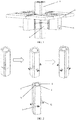
- the folding slab and central column composite joint mainly comprises a steel-wood composite column, square wood beams, connecting assemblies for connecting the steel-wood composite column and the square wood beams, and folding wood slabs connected with and supported by the steel-wood composite column, the square wood beams and the connecting assemblies;
- the steel-wood composite column comprises a hollow cross-shaped outer wood column, wherein a steel sleeve is inlaid in the cross-shaped outer wood column, an inner wood column is inlaid in the steel sleeve, column vertical steel bars penetrate through the inner wood column, inner ends of horizontal steel bars penetrate through the cross-shaped outer wood column to be fixedly connected to the steel sleeve, tapered threads are arranged at outer ends of the horizontal steel bars, and first bolt holes to be connected to the connecting assemblies are formed in two sides of a cross-shaped surface of the cross-shaped outer wood column;
- a spindle is connected between every two adjacent folding wood slabs, and third bolt holes to be connected to the square wood beams and the connecting assemblies are formed in edge joints of the folding wood slabs;
- the square wood beams have vertical protruding steel bars stretching therein, and threads are arranged at outer ends of the vertical protruding steel bars;
- Each connecting assembly comprises a threaded sleeve having two ends respectively connected to the horizontal steel bars and vertical protruding steel bars, and a double ring plate;
- Second bolt holes to be connected to the double ring plates are formed in two sides of the ends of the square wood beams, and third bolt holes to be fixedly connected to the folding wood slabs are formed in the tops of the square wood beams;
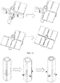
- the double ring plate comprises a cross-shaped upper ring plate and a cross-shaped lower ring plate, wherein corner plates are arranged on connected cross-shaped roots of the upper ring plate and the lower ring plate, and fourth bolt holes used for fixed connection after the upper ring plate and the lower ring plate are overlapped are formed in the corner plates; first bolt holes to be connected to the cross-shaped outer wood column are formed in inner ends, close to the cross-shaped roots, of the upper ring plate and the lower ring plate; second bolt holes to be connected to the square wood beams are formed in outer sides of the ends of the upper ring plate and the lower ring plate; and third bolt holes to be connected to the square wood beams and the folding wood slabs are formed in the top ends of the upper ring plate and the lower ring plate.
- the folding slab and prefabricated column-beam composite joint of the present application adopts a steel-wood composite structure, formed by combining a steel structure and a wood structure, to give full play to the excellent properties of different materials and is of important significance for guaranteeing the overall seismic performance and disaster-prevention performance of buildings.
- the folding slab and central column composite joint of the steel-wood composite structure complementation of materials is realized by combining two materials, so that the strength of the wood structure is obviously improved; by adding the wood structure in the steel structure, the structural weight can be reduced, the structural strength per unit mass is improved, and the durability is extremely high.
- the modular structure allows materials to be obtained easily, and the construction speed is high.
- the beams and the column are mechanically connected by means of steel, so that the strength of the joint is improved, and quality problems caused by welding are reduced; by adding the steel structure in the wood column structure, the overall bearing capacity of the wood structure is remarkably improved; and the entire composite joint has high strength, the probability of joint destruction can be lowered to a certain extent, and the joint is restorable.
- the strength of the steel sleeve of the steel-wood composite column is greatly improved, the horizontal steel bars arranged in the cross-shaped outer wood column can greatly improve the stress performance and seismic performance, and the bearing capacity per unit mass of the steel-wood composite column is higher than that of pure wood structures.
- the column vertical steel bars are arranged in the inner wood column of the steel-wood composite column, so that the pressure-bearing performance and tensile strength of the wood column is improved, and the seismic performance per unit mass is superior.
- the vertical steel bars in the square wood beams can remarkably enhance the tensile strength of the beams to ensure that the square wood beams have good seismic performance per unit mass.
- the spindles are arranged in the folding slabs, so that splicing between every two adjacent slabs is reduced, good assembly performance is realized, the construction efficiency is improved accordingly, the construction cost is reduced, and the level of standardization and productization of building construction is high.
- the cross-shaped outer wood column and the square wood beams are mechanically connected by the connecting assemblies adopting the threaded steel bar sleeves, connection is easy and convenient, and welding is not needed, so that the construction quality and efficiency are greatly improved; and the double ring plates are formed by overlapped connection of the upper and lower ring plates of the same structure, can further enhance the connection on the basis of the threaded sleeves, and can remarkably improve the strength of beam-column joints, so that shear failures of welded parts of the beam-column joint in an earthquake are effectively reduced, and good semiotic performance is realized.
- the upper ring plate and lower ring plate of the double ring plate have cross-shaped slots identical in shape with the cross-shaped outer wood column. After the entire composite joint is assembled, the steel-wood composite column can penetrate through the connecting assemblies via the cross-shaped slots, and finally, basic connection of the central column composite joint is completed.
- transitional, reinforced and fastened connection of the slabs with the beams and the column is realized, that is, an existing steel bar welding process can be replaced on the basis of mechanical connection of the threaded sleeves, the steel bars in the beams and the steel bars in the column, so that quality problems caused by welding can be avoided.
- dovetail concave grooves and dovetail convex grooves used for insertion are symmetrically formed in connected edges of the upper ring plates and the lower ring plates, that is, the upper ring plates and the lower ring plates can be stably connected in an inserted manner by means of the dovetail groove structures.
- Near-column slabs and square slabs of the folding wood slabs are connected through the spindles, W-shaped slots matched with the cross-shaped outer wood column are formed in near-column ends of the near-column slabs, and a cross-shaped slot is formed by the W-shaped slots of the four adjacent near-column slabs.
- the four adjacent near-column slabs of the folding wood slabs are disposed around the steel-wood composite column, and the square slabs encircle the near-column slabs.
- the fixation manner of the assembled slabs can effectively improve the construction efficiency of the slabs, further improve the fixed connection of the slabs, the beams and the column, and realize cyclically developing buildings.
- the present application further provides a corresponding assembly method, which comprises:
- the folding slab and central column composite joint and the assembly method thereof provided by the present application have the following advantages:
- 1 steel-wood composite column; 2, square wood beam; 3, folding wood slab; 4, connecting assembly; 5, cross-shaped outer wood column; 6, column vertical steel bar; 7, horizontal steel bar; 8, steel sleeve; 9, threaded sleeve; 10, vertical protruding steel bar; 11, double ring plate; 12, first bolt hole; 13, second bolt hole; 14, third bolt hole; 15, corner plate; 16, spindle; 17, near-column slab; 18, square slab; 19, inner wood column; 20, fourth bolt hole; 21, cross-shaped slot; 22, cross-shaped slot; 23, dovetail concave groove; 24, dovetail convex groove; 123, upper ring plate; 456, lower ring plate.
- Embodiment 1 A detailed description of the embodiments of the present application is given below in conjunction with the accompanying drawings.
- a folding slab and central column composite joint mainly comprises a steel-wood composite column 1, square wood beams 2, folding wood slabs 3 and connecting assemblies 4.
- the steel-wood composite column 1 comprises a hollow cross-shaped outer wood column 5, wherein a cylindrical steel sleeve 8 is inlaid in the cross-shaped outer wood column 5, a cylindrical inner wood column 19 is inlaid in the steel sleeve 8, column vertical steel bars 6 penetrate through the inner wood column 19, inner ends of horizontal steel bars 7 penetrate through the cross-shaped outer wood column 5 to be welded and fixed to the steel sleeve 8, tapered threads are arranged at outer ends of the horizontal steel bars 7, and first bolt holes 12 to be connected to the connecting assemblies 4 are formed in two sides of a cross-shaped surface of the cross-shaped outer wood column 5;
- the square wood beams 2 have vertical protruding steel bars 10 stretching therein, and tapered threads are arranged at outer ends of the vertical protruding steel bars 10; second bolt holes 13 to be connected to the connecting assemblies 4 are formed in two sides of the ends of the square wood beams 2, and third bolt holes 14 to be connected to the folding wood slabs 3 are formed in the tops of the square wood beams 2;
- a spindle 16 is connected between every two adjacent folding wood slabs 3, and third bolt holes 14 to be connected to the square wood beams 2 and the connecting assemblies 4 are formed in edge joints of the folding wood slabs; and particularly, near-column slabs 17 and square slabs 18 are connected through the spindles 16, W-shaped slots matched with the cross-shaped outer wood column 5 are formed in near-column ends of the near-column slabs 17, and a cross-shaped slot 22 is formed by the W-shaped slots of the four adjacent near-column slabs 17; and
- Each connecting assembly 4 comprises a tapered threaded sleeve 9 having two ends respectively connected to the horizontal steel bars 7 and the vertical protruding steel bars 10, and a double ring plate 11, wherein the double ring plate 11 comprises a cross-shaped upper ring plate 123 and a cross-shaped lower ring plate 456, which are of the same structure, are correspondingly connected in an overlapped manner, and are inserted into each other by means of dovetail concave grooves 23 and dovetail convex grooves 24; corner plates 15 are arranged on connected cross-shaped roots of the upper ring plate 123 and the lower ring plate 456, and the upper ring plate 123 and the lower ring plate 456 have cross-shaped slots 21 which are identical in shape with the cross-shaped outer wood columns 5; the corner plates 15 have fourth bolt holes 20 used for fixed connection after the upper and lower ring plates are overlapped; first bolt holes 12 to be connected to the cross-shaped outer wood column 5 are formed in inner ends, close to the cross-shaped roots, of the upper ring plate
- an assembly method of the composite joint is implemented through the following steps:
- the wood structure is easy to process, low in weight and high in strength and has good seismic performance
- the steel structure is uniform in texture and good in strength, plasticity and tenacity, and bean-column components in the structure can be connected through bolts, so that the components of the joint can be replaced, and the overall life of the structure is prolonged
- the square wood beams adopted by the composite joint have better shear resistance
- the steel bars are arranged in the square wood beams, so that the stress performance of the column is improved
- completely prefabricated construction is realized, the construction progress is accelerated, the construction period is shortened, and the construction cost is reduced
- steel is added to the wood structure to improve the tension resistance, compression resistance and bending resistance of the wood structure, so that the wood structure has good seismic performance under the effect of an earthquake.
Landscapes
- Engineering & Computer Science (AREA)
- Architecture (AREA)
- Civil Engineering (AREA)
- Structural Engineering (AREA)
- Physics & Mathematics (AREA)
- Electromagnetism (AREA)
- Life Sciences & Earth Sciences (AREA)
- Wood Science & Technology (AREA)
- Chemical & Material Sciences (AREA)
- Composite Materials (AREA)
- Joining Of Building Structures In Genera (AREA)
- Rod-Shaped Construction Members (AREA)
Applications Claiming Priority (2)
| Application Number | Priority Date | Filing Date | Title |
|---|---|---|---|
| CN201910832774.3A CN110616807B (zh) | 2019-09-04 | 2019-09-04 | 折叠式楼板中柱组合节点及其组装方法 |
| PCT/CN2020/089293 WO2021042757A1 (zh) | 2019-09-04 | 2020-05-09 | 折叠式楼板中柱组合节点及其组装方法 |
Publications (4)
| Publication Number | Publication Date |
|---|---|
| EP3865632A1 true EP3865632A1 (de) | 2021-08-18 |
| EP3865632A4 EP3865632A4 (de) | 2022-02-23 |
| EP3865632B1 EP3865632B1 (de) | 2022-11-30 |
| EP3865632B8 EP3865632B8 (de) | 2023-01-11 |
Family
ID=68922510
Family Applications (1)
| Application Number | Title | Priority Date | Filing Date |
|---|---|---|---|
| EP20859999.3A Active EP3865632B8 (de) | 2019-09-04 | 2020-05-09 | Mittelsäulenverbundgelenke für faltbare bodenplatte und montageverfahren dafür |
Country Status (5)
| Country | Link |
|---|---|
| US (1) | US10822789B1 (de) |
| EP (1) | EP3865632B8 (de) |
| JP (1) | JP6802595B1 (de) |
| CN (1) | CN110616807B (de) |
| WO (1) | WO2021042757A1 (de) |
Families Citing this family (24)
| Publication number | Priority date | Publication date | Assignee | Title |
|---|---|---|---|---|
| CN109853739B (zh) * | 2019-02-27 | 2020-06-23 | 青岛理工大学 | 装配式钢木组合节点 |
| CN110616808B (zh) * | 2019-09-04 | 2020-07-14 | 青岛理工大学 | 拼装楼板式钢木组合节点及其组装方法 |
| CN110616807B (zh) * | 2019-09-04 | 2020-07-14 | 青岛理工大学 | 折叠式楼板中柱组合节点及其组装方法 |
| CN110644619B (zh) * | 2019-09-21 | 2020-10-09 | 青岛理工大学 | 装配式限位增强钢木磨砂套筒组合节点 |
| CN210828440U (zh) * | 2019-09-29 | 2020-06-23 | 丰和营造集团股份有限公司 | 一种建筑物到期前混凝土楼层加固结构 |
| CN111677172B (zh) * | 2020-06-03 | 2021-05-25 | 苏州科技大学 | 钢-混凝土组合结构板柱结构体系 |
| MX2023004997A (es) * | 2020-11-02 | 2023-07-24 | Tindall Corp | Aparatos y métodos para construir una estructura de concreto utilizando componentes de concreto prefabricado. |
| CN113356393B (zh) * | 2021-05-08 | 2023-12-05 | 承德建元科技股份有限公司 | 一种预制墙体的拼接结构及其拼接方法 |
| CN113565204B (zh) * | 2021-08-17 | 2022-10-25 | 江苏南通六建建设集团有限公司 | 一种复合型结构柱就位穿筋法抗震节点构造及施工方法 |
| CN113882512B (zh) * | 2021-08-30 | 2023-03-28 | 西安建筑科技大学 | 一种带套环的工字梁-方钢管柱装配式节点 |
| CN114250863A (zh) * | 2021-12-24 | 2022-03-29 | 常州工学院 | 一种钢插板连接的焊接空心球节点 |
| CN114197654B (zh) * | 2021-12-29 | 2023-05-02 | 浙江华策工程设计建设集团有限公司 | 一种古建筑的木梁与钢结构柱的固定结构 |
| CN114197655B (zh) * | 2021-12-29 | 2023-08-18 | 山东建筑大学工程鉴定加固研究院有限公司 | 一种竹木结构梁柱节点及方法 |
| US11702835B1 (en) * | 2022-01-17 | 2023-07-18 | Mehmet Baris Batukan | Self-aligning modular connector |
| CN114263296B (zh) * | 2022-02-17 | 2024-05-24 | 石家庄铁道大学 | 一种拼装式钢木组合剪力墙结构体系 |
| CN114607083B (zh) * | 2022-03-23 | 2024-06-14 | 山东佳隆建工集团有限公司 | 一种用于装配式建筑用骨架板材的承重结构及其安装方法 |
| CN114622657B (zh) * | 2022-04-24 | 2023-12-05 | 石家庄铁道大学 | 基于套筒连接的钢木组合连接体系 |
| CN114922347B (zh) * | 2022-05-20 | 2026-03-20 | 上海市建筑科学研究院有限公司 | 大跨度耗能工程竹木钢网架组合结构 |
| CN115262832B (zh) * | 2022-08-15 | 2023-10-24 | 四川大学 | 一种螺栓连接装配式钢筋混凝土双向肋保温楼盖 |
| CN115839103A (zh) * | 2022-10-13 | 2023-03-24 | 中建六局(天津)绿色建筑科技有限公司 | 一种预制组合轨顶风道侧墙结构及其连接方法 |
| CN116044018B (zh) * | 2023-01-10 | 2025-06-24 | 深圳市中集建筑设计院有限公司 | 一种模块建设注浆抗剪连接节点结构及其施工方法 |
| CN116275901A (zh) * | 2023-03-13 | 2023-06-23 | 北京航星机器制造有限公司 | 一种十字形空间五通接头的加工方法 |
| CN117266356B (zh) * | 2023-10-07 | 2026-01-13 | 安徽翔誉千秋建设集团有限公司 | 一种屋面钢结构支撑装置 |
| CN120700993B (zh) * | 2025-08-29 | 2025-12-02 | 石家庄睿民慧筑科技有限公司 | 一种建筑用多层框架结构及施工方法 |
Family Cites Families (26)
| Publication number | Priority date | Publication date | Assignee | Title |
|---|---|---|---|---|
| US3828512A (en) * | 1972-01-20 | 1974-08-13 | D Johnson | Method of forming a multi-unit folding slab construction for use on restricted building site |
| JPS52101816A (en) * | 1976-02-23 | 1977-08-26 | Katsuta Minoru | Building that use cross pillar and beam |
| DE2702310A1 (de) * | 1977-01-21 | 1978-07-27 | Otto Kreibaum | Aus vorfabrizierten teilen zusammensetzbares haus |
| JPS56167039A (en) * | 1980-05-24 | 1981-12-22 | Yoshiaki Kimura | Execution of building utilizing sleeve pin, concave and column |
| CN1114741C (zh) * | 1999-03-18 | 2003-07-16 | 段梦麟 | 一种配筋的人造木 |
| JP2002013201A (ja) * | 2000-06-29 | 2002-01-18 | Uesuto:Kk | 木造建築物の接合構造 |
| US7343713B2 (en) * | 2003-03-07 | 2008-03-18 | Morton Buildings | Hinged support column |
| US7100332B2 (en) * | 2004-08-26 | 2006-09-05 | Loesch Ivan L | Unfolding modular building system |
| KR100579702B1 (ko) * | 2005-07-19 | 2006-05-15 | 한진수 | 건축용 구조부재 |
| US20070062147A1 (en) * | 2005-07-27 | 2007-03-22 | Clifford Wright | Portable folding floor unit |
| US7637076B2 (en) * | 2006-03-10 | 2009-12-29 | Vaughn Willaim B | Moment-resistant building column insert system and method |
| US9523188B2 (en) * | 2007-06-22 | 2016-12-20 | Diversakore Llc | Framing structure |
| KR101157147B1 (ko) * | 2008-09-22 | 2012-06-22 | 경희대학교 산학협력단 | 콘크리트 복합 기둥 및 이를 이용한 건축물 시공방법 |
| CN102155053A (zh) * | 2011-03-25 | 2011-08-17 | 扬州市天成建筑安装工程有限公司 | 一种柱梁连接十字型耗能卡套 |
| WO2015038805A1 (en) * | 2013-09-11 | 2015-03-19 | Aditazz, Inc. | Concrete deck for an integrated building system assembly platfrom |
| CN103603431A (zh) * | 2013-10-15 | 2014-02-26 | 南京工业大学 | 装配式木结构梁柱植筋节点 |
| US9879413B2 (en) * | 2014-02-13 | 2018-01-30 | Settimio CASTELLI | Modular structural system |
| CN204311633U (zh) * | 2014-12-02 | 2015-05-06 | 何敏娟 | 钢边梁木规格材预制楼板结构 |
| CN104727439B (zh) | 2015-03-09 | 2017-01-18 | 沈阳建筑大学 | 装配式混凝土柱、梁结构及装配连接方法 |
| CA2982618C (en) * | 2015-04-15 | 2023-09-26 | Vectorbloc Corp. | Connector for modular building structure |
| CN109072602B (zh) * | 2016-01-14 | 2021-06-01 | 安德里斯·奥雷·劳 | 结构元件 |
| CN106088471B (zh) * | 2016-06-12 | 2019-09-06 | 广东电白二建集团有限公司 | 一种仿古建筑梁柱木包钢结构施工方法 |
| JP7033871B2 (ja) * | 2017-09-19 | 2022-03-11 | 大成建設株式会社 | 鋼管と木質材の合成柱 |
| CN108978869B (zh) * | 2018-08-30 | 2024-01-19 | 海南华金钢构有限公司 | 一种装配式钢木组合梁柱节点结构及其施工方法 |
| CN109853739B (zh) * | 2019-02-27 | 2020-06-23 | 青岛理工大学 | 装配式钢木组合节点 |
| CN110616807B (zh) * | 2019-09-04 | 2020-07-14 | 青岛理工大学 | 折叠式楼板中柱组合节点及其组装方法 |
-
2019
- 2019-09-04 CN CN201910832774.3A patent/CN110616807B/zh active Active
-
2020
- 2020-05-09 WO PCT/CN2020/089293 patent/WO2021042757A1/zh not_active Ceased
- 2020-05-09 EP EP20859999.3A patent/EP3865632B8/de active Active
- 2020-07-22 JP JP2020124933A patent/JP6802595B1/ja not_active Expired - Fee Related
- 2020-07-27 US US16/939,092 patent/US10822789B1/en not_active Expired - Fee Related
Also Published As
| Publication number | Publication date |
|---|---|
| JP6802595B1 (ja) | 2020-12-16 |
| EP3865632B1 (de) | 2022-11-30 |
| WO2021042757A1 (zh) | 2021-03-11 |
| CN110616807A (zh) | 2019-12-27 |
| EP3865632A4 (de) | 2022-02-23 |
| US10822789B1 (en) | 2020-11-03 |
| JP2021038639A (ja) | 2021-03-11 |
| CN110616807B (zh) | 2020-07-14 |
| EP3865632B8 (de) | 2023-01-11 |
Similar Documents
| Publication | Publication Date | Title |
|---|---|---|
| EP3865632B1 (de) | Mittelsäulenverbundgelenke für faltbare bodenplatte und montageverfahren dafür | |
| US10914061B1 (en) | Assembled slab steel-wood composite joint and assembly method thereof | |
| US10876282B1 (en) | Fabricated limiting-reinforced steel-wood frosted sleeve composite joint | |
| EP3708731B1 (de) | Zusammengebaute selbstwiederherstellende scherwandstruktur einer doppelstahlplatte vom energiedissipationstyp | |
| CN110241914B (zh) | 刚度可控装配式节点构造及其施工方法 | |
| CN113293858B (zh) | 一种快速分梁器及装配插入式混凝土叠合梁柱结构 | |
| CN110725402B (zh) | 多腔体组合剪力墙与h型钢梁装配式节点及其施工方法 | |
| CN215367377U (zh) | 全装配式风力发电机组基础及风力发电机组 | |
| KR102554408B1 (ko) | 접합용 수직부재를 이용한 프리캐스트 콘크리트 합성기둥의 매입형 접합부 구조 | |
| CN213014816U (zh) | 混凝土钢结构预制剪力墙 | |
| CN216865443U (zh) | 一种装配式混凝土柱与钢梁的rcs组合件 | |
| KR20040043202A (ko) | 철근콘크리트 기둥 및 철골 보의 접합부 | |
| CN212358587U (zh) | 一种具有连接节点的装配式混凝土框架结构梁柱 | |
| CN213358935U (zh) | 一种装配式梁柱节点结构 | |
| CN215211577U (zh) | 一种易于搭建的梁柱节点结构 | |
| CN108487549A (zh) | 装配式功能可恢复钢骨架混凝土组合柱及安装方法 | |
| CN217078758U (zh) | 一种用于基坑支护的装配式悬吊支撑装置 | |
| CN115126320A (zh) | 一种装配式可更换梁柱连接节点结构 | |
| CN221567492U (zh) | 一种装配式建筑用梁、柱连接节点 | |
| CN116220228B (zh) | 高耗能钢管混凝土梁柱节点结构及施工方法 | |
| CN213174217U (zh) | 一种预制混凝土框架与钢支撑装配连接结构 | |
| CN113898121B (zh) | 一种用于装配式钢结构的井字形模块化拼接桁架 | |
| CN218667900U (zh) | 一种新型对穿式梁柱刚接节点 | |
| CN223867534U (zh) | 一种圆形钢管混凝土隔震柱 | |
| CN114277944B (zh) | 一种装配式钢木组合节点及其装配方法 |
Legal Events
| Date | Code | Title | Description |
|---|---|---|---|
| STAA | Information on the status of an ep patent application or granted ep patent |
Free format text: STATUS: THE INTERNATIONAL PUBLICATION HAS BEEN MADE |
|
| PUAI | Public reference made under article 153(3) epc to a published international application that has entered the european phase |
Free format text: ORIGINAL CODE: 0009012 |
|
| STAA | Information on the status of an ep patent application or granted ep patent |
Free format text: STATUS: REQUEST FOR EXAMINATION WAS MADE |
|
| 17P | Request for examination filed |
Effective date: 20210514 |
|
| AK | Designated contracting states |
Kind code of ref document: A1 Designated state(s): AL AT BE BG CH CY CZ DE DK EE ES FI FR GB GR HR HU IE IS IT LI LT LU LV MC MK MT NL NO PL PT RO RS SE SI SK SM TR |
|
| A4 | Supplementary search report drawn up and despatched |
Effective date: 20220120 |
|
| RIC1 | Information provided on ipc code assigned before grant |
Ipc: E04C 3/36 20060101ALI20220114BHEP Ipc: E04B 1/26 20060101ALI20220114BHEP Ipc: E04B 5/14 20060101ALI20220114BHEP Ipc: E04B 5/12 20060101ALI20220114BHEP Ipc: E04C 3/292 20060101ALI20220114BHEP Ipc: E04B 1/18 20060101ALI20220114BHEP Ipc: E04B 5/02 20060101ALI20220114BHEP Ipc: E04B 1/30 20060101AFI20220114BHEP |
|
| RIC1 | Information provided on ipc code assigned before grant |
Ipc: E04C 3/36 20060101ALI20220318BHEP Ipc: E04B 1/26 20060101ALI20220318BHEP Ipc: E04B 5/14 20060101ALI20220318BHEP Ipc: E04B 5/12 20060101ALI20220318BHEP Ipc: E04C 3/292 20060101ALI20220318BHEP Ipc: E04B 1/18 20060101ALI20220318BHEP Ipc: E04B 5/02 20060101ALI20220318BHEP Ipc: E04B 1/30 20060101AFI20220318BHEP |
|
| GRAP | Despatch of communication of intention to grant a patent |
Free format text: ORIGINAL CODE: EPIDOSNIGR1 |
|
| STAA | Information on the status of an ep patent application or granted ep patent |
Free format text: STATUS: GRANT OF PATENT IS INTENDED |
|
| DAV | Request for validation of the european patent (deleted) | ||
| DAX | Request for extension of the european patent (deleted) | ||
| INTG | Intention to grant announced |
Effective date: 20220516 |
|
| RAP1 | Party data changed (applicant data changed or rights of an application transferred) |
Owner name: SUZHOU UNIVERSITY OF SCIENCE AND TECHNOLOGY |
|
| RIN1 | Information on inventor provided before grant (corrected) |
Inventor name: LIU, YI Inventor name: NING, NING Inventor name: WANG, YAN Inventor name: MOU, BEN |
|
| GRAJ | Information related to disapproval of communication of intention to grant by the applicant or resumption of examination proceedings by the epo deleted |
Free format text: ORIGINAL CODE: EPIDOSDIGR1 |
|
| STAA | Information on the status of an ep patent application or granted ep patent |
Free format text: STATUS: REQUEST FOR EXAMINATION WAS MADE |
|
| RIN1 | Information on inventor provided before grant (corrected) |
Inventor name: NING, NING Inventor name: WANG, YAN Inventor name: LIU, YI Inventor name: MOU, BEN Inventor name: LI, MING |
|
| GRAS | Grant fee paid |
Free format text: ORIGINAL CODE: EPIDOSNIGR3 |
|
| STAA | Information on the status of an ep patent application or granted ep patent |
Free format text: STATUS: GRANT OF PATENT IS INTENDED |
|
| GRAP | Despatch of communication of intention to grant a patent |
Free format text: ORIGINAL CODE: EPIDOSNIGR1 |
|
| INTC | Intention to grant announced (deleted) | ||
| GRAA | (expected) grant |
Free format text: ORIGINAL CODE: 0009210 |
|
| STAA | Information on the status of an ep patent application or granted ep patent |
Free format text: STATUS: THE PATENT HAS BEEN GRANTED |
|
| INTG | Intention to grant announced |
Effective date: 20221011 |
|
| AK | Designated contracting states |
Kind code of ref document: B1 Designated state(s): AL AT BE BG CH CY CZ DE DK EE ES FI FR GB GR HR HU IE IS IT LI LT LU LV MC MK MT NL NO PL PT RO RS SE SI SK SM TR |
|
| REG | Reference to a national code |
Ref country code: CH Ref legal event code: EP Ref country code: GB Ref legal event code: FG4D |
|
| GRAT | Correction requested after decision to grant or after decision to maintain patent in amended form |
Free format text: ORIGINAL CODE: EPIDOSNCDEC |
|
| REG | Reference to a national code |
Ref country code: CH Ref legal event code: PK Free format text: BERICHTIGUNGEN Ref country code: CH Ref legal event code: PK Free format text: BERICHTIGUNG B8 Ref country code: AT Ref legal event code: REF Ref document number: 1534789 Country of ref document: AT Kind code of ref document: T Effective date: 20221215 Ref country code: DE Ref legal event code: R096 Ref document number: 602020006682 Country of ref document: DE |
|
| REG | Reference to a national code |
Ref country code: IE Ref legal event code: FG4D |
|
| RIN2 | Information on inventor provided after grant (corrected) |
Inventor name: NING, NING Inventor name: WANG, YAN Inventor name: LIU, YI Inventor name: MOU, BEN Inventor name: LI, MING |
|
| REG | Reference to a national code |
Ref country code: LT Ref legal event code: MG9D |
|
| REG | Reference to a national code |
Ref country code: NL Ref legal event code: MP Effective date: 20221130 |
|
| PG25 | Lapsed in a contracting state [announced via postgrant information from national office to epo] |
Ref country code: SE Free format text: LAPSE BECAUSE OF FAILURE TO SUBMIT A TRANSLATION OF THE DESCRIPTION OR TO PAY THE FEE WITHIN THE PRESCRIBED TIME-LIMIT Effective date: 20221130 Ref country code: PT Free format text: LAPSE BECAUSE OF FAILURE TO SUBMIT A TRANSLATION OF THE DESCRIPTION OR TO PAY THE FEE WITHIN THE PRESCRIBED TIME-LIMIT Effective date: 20230331 Ref country code: NO Free format text: LAPSE BECAUSE OF FAILURE TO SUBMIT A TRANSLATION OF THE DESCRIPTION OR TO PAY THE FEE WITHIN THE PRESCRIBED TIME-LIMIT Effective date: 20230228 Ref country code: LT Free format text: LAPSE BECAUSE OF FAILURE TO SUBMIT A TRANSLATION OF THE DESCRIPTION OR TO PAY THE FEE WITHIN THE PRESCRIBED TIME-LIMIT Effective date: 20221130 Ref country code: FI Free format text: LAPSE BECAUSE OF FAILURE TO SUBMIT A TRANSLATION OF THE DESCRIPTION OR TO PAY THE FEE WITHIN THE PRESCRIBED TIME-LIMIT Effective date: 20221130 Ref country code: ES Free format text: LAPSE BECAUSE OF FAILURE TO SUBMIT A TRANSLATION OF THE DESCRIPTION OR TO PAY THE FEE WITHIN THE PRESCRIBED TIME-LIMIT Effective date: 20221130 |
|
| REG | Reference to a national code |
Ref country code: AT Ref legal event code: MK05 Ref document number: 1534789 Country of ref document: AT Kind code of ref document: T Effective date: 20221130 |
|
| PG25 | Lapsed in a contracting state [announced via postgrant information from national office to epo] |
Ref country code: RS Free format text: LAPSE BECAUSE OF FAILURE TO SUBMIT A TRANSLATION OF THE DESCRIPTION OR TO PAY THE FEE WITHIN THE PRESCRIBED TIME-LIMIT Effective date: 20221130 Ref country code: PL Free format text: LAPSE BECAUSE OF FAILURE TO SUBMIT A TRANSLATION OF THE DESCRIPTION OR TO PAY THE FEE WITHIN THE PRESCRIBED TIME-LIMIT Effective date: 20221130 Ref country code: LV Free format text: LAPSE BECAUSE OF FAILURE TO SUBMIT A TRANSLATION OF THE DESCRIPTION OR TO PAY THE FEE WITHIN THE PRESCRIBED TIME-LIMIT Effective date: 20221130 Ref country code: IS Free format text: LAPSE BECAUSE OF FAILURE TO SUBMIT A TRANSLATION OF THE DESCRIPTION OR TO PAY THE FEE WITHIN THE PRESCRIBED TIME-LIMIT Effective date: 20230330 Ref country code: HR Free format text: LAPSE BECAUSE OF FAILURE TO SUBMIT A TRANSLATION OF THE DESCRIPTION OR TO PAY THE FEE WITHIN THE PRESCRIBED TIME-LIMIT Effective date: 20221130 Ref country code: GR Free format text: LAPSE BECAUSE OF FAILURE TO SUBMIT A TRANSLATION OF THE DESCRIPTION OR TO PAY THE FEE WITHIN THE PRESCRIBED TIME-LIMIT Effective date: 20230301 |
|
| PG25 | Lapsed in a contracting state [announced via postgrant information from national office to epo] |
Ref country code: NL Free format text: LAPSE BECAUSE OF FAILURE TO SUBMIT A TRANSLATION OF THE DESCRIPTION OR TO PAY THE FEE WITHIN THE PRESCRIBED TIME-LIMIT Effective date: 20221130 |
|
| PG25 | Lapsed in a contracting state [announced via postgrant information from national office to epo] |
Ref country code: SM Free format text: LAPSE BECAUSE OF FAILURE TO SUBMIT A TRANSLATION OF THE DESCRIPTION OR TO PAY THE FEE WITHIN THE PRESCRIBED TIME-LIMIT Effective date: 20221130 Ref country code: RO Free format text: LAPSE BECAUSE OF FAILURE TO SUBMIT A TRANSLATION OF THE DESCRIPTION OR TO PAY THE FEE WITHIN THE PRESCRIBED TIME-LIMIT Effective date: 20221130 Ref country code: EE Free format text: LAPSE BECAUSE OF FAILURE TO SUBMIT A TRANSLATION OF THE DESCRIPTION OR TO PAY THE FEE WITHIN THE PRESCRIBED TIME-LIMIT Effective date: 20221130 Ref country code: DK Free format text: LAPSE BECAUSE OF FAILURE TO SUBMIT A TRANSLATION OF THE DESCRIPTION OR TO PAY THE FEE WITHIN THE PRESCRIBED TIME-LIMIT Effective date: 20221130 Ref country code: CZ Free format text: LAPSE BECAUSE OF FAILURE TO SUBMIT A TRANSLATION OF THE DESCRIPTION OR TO PAY THE FEE WITHIN THE PRESCRIBED TIME-LIMIT Effective date: 20221130 Ref country code: AT Free format text: LAPSE BECAUSE OF FAILURE TO SUBMIT A TRANSLATION OF THE DESCRIPTION OR TO PAY THE FEE WITHIN THE PRESCRIBED TIME-LIMIT Effective date: 20221130 |
|
| PG25 | Lapsed in a contracting state [announced via postgrant information from national office to epo] |
Ref country code: SK Free format text: LAPSE BECAUSE OF FAILURE TO SUBMIT A TRANSLATION OF THE DESCRIPTION OR TO PAY THE FEE WITHIN THE PRESCRIBED TIME-LIMIT Effective date: 20221130 Ref country code: AL Free format text: LAPSE BECAUSE OF FAILURE TO SUBMIT A TRANSLATION OF THE DESCRIPTION OR TO PAY THE FEE WITHIN THE PRESCRIBED TIME-LIMIT Effective date: 20221130 |
|
| REG | Reference to a national code |
Ref country code: DE Ref legal event code: R097 Ref document number: 602020006682 Country of ref document: DE |
|
| PLBE | No opposition filed within time limit |
Free format text: ORIGINAL CODE: 0009261 |
|
| STAA | Information on the status of an ep patent application or granted ep patent |
Free format text: STATUS: NO OPPOSITION FILED WITHIN TIME LIMIT |
|
| 26N | No opposition filed |
Effective date: 20230831 |
|
| PG25 | Lapsed in a contracting state [announced via postgrant information from national office to epo] |
Ref country code: SI Free format text: LAPSE BECAUSE OF FAILURE TO SUBMIT A TRANSLATION OF THE DESCRIPTION OR TO PAY THE FEE WITHIN THE PRESCRIBED TIME-LIMIT Effective date: 20221130 |
|
| REG | Reference to a national code |
Ref country code: DE Ref legal event code: R119 Ref document number: 602020006682 Country of ref document: DE |
|
| REG | Reference to a national code |
Ref country code: CH Ref legal event code: PL |
|
| PG25 | Lapsed in a contracting state [announced via postgrant information from national office to epo] |
Ref country code: MC Free format text: LAPSE BECAUSE OF FAILURE TO SUBMIT A TRANSLATION OF THE DESCRIPTION OR TO PAY THE FEE WITHIN THE PRESCRIBED TIME-LIMIT Effective date: 20221130 |
|
| REG | Reference to a national code |
Ref country code: BE Ref legal event code: MM Effective date: 20230531 |
|
| PG25 | Lapsed in a contracting state [announced via postgrant information from national office to epo] |
Ref country code: MC Free format text: LAPSE BECAUSE OF FAILURE TO SUBMIT A TRANSLATION OF THE DESCRIPTION OR TO PAY THE FEE WITHIN THE PRESCRIBED TIME-LIMIT Effective date: 20221130 Ref country code: LU Free format text: LAPSE BECAUSE OF NON-PAYMENT OF DUE FEES Effective date: 20230509 Ref country code: LI Free format text: LAPSE BECAUSE OF NON-PAYMENT OF DUE FEES Effective date: 20230531 Ref country code: CH Free format text: LAPSE BECAUSE OF NON-PAYMENT OF DUE FEES Effective date: 20230531 |
|
| REG | Reference to a national code |
Ref country code: IE Ref legal event code: MM4A |
|
| PG25 | Lapsed in a contracting state [announced via postgrant information from national office to epo] |
Ref country code: IE Free format text: LAPSE BECAUSE OF NON-PAYMENT OF DUE FEES Effective date: 20230509 |
|
| PG25 | Lapsed in a contracting state [announced via postgrant information from national office to epo] |
Ref country code: IE Free format text: LAPSE BECAUSE OF NON-PAYMENT OF DUE FEES Effective date: 20230509 Ref country code: DE Free format text: LAPSE BECAUSE OF NON-PAYMENT OF DUE FEES Effective date: 20231201 |
|
| PG25 | Lapsed in a contracting state [announced via postgrant information from national office to epo] |
Ref country code: IT Free format text: LAPSE BECAUSE OF FAILURE TO SUBMIT A TRANSLATION OF THE DESCRIPTION OR TO PAY THE FEE WITHIN THE PRESCRIBED TIME-LIMIT Effective date: 20221130 Ref country code: FR Free format text: LAPSE BECAUSE OF NON-PAYMENT OF DUE FEES Effective date: 20230531 Ref country code: BE Free format text: LAPSE BECAUSE OF NON-PAYMENT OF DUE FEES Effective date: 20230531 |
|
| PG25 | Lapsed in a contracting state [announced via postgrant information from national office to epo] |
Ref country code: BG Free format text: LAPSE BECAUSE OF FAILURE TO SUBMIT A TRANSLATION OF THE DESCRIPTION OR TO PAY THE FEE WITHIN THE PRESCRIBED TIME-LIMIT Effective date: 20221130 |
|
| PG25 | Lapsed in a contracting state [announced via postgrant information from national office to epo] |
Ref country code: BG Free format text: LAPSE BECAUSE OF FAILURE TO SUBMIT A TRANSLATION OF THE DESCRIPTION OR TO PAY THE FEE WITHIN THE PRESCRIBED TIME-LIMIT Effective date: 20221130 |
|
| GBPC | Gb: european patent ceased through non-payment of renewal fee |
Effective date: 20240509 |
|
| PG25 | Lapsed in a contracting state [announced via postgrant information from national office to epo] |
Ref country code: GB Free format text: LAPSE BECAUSE OF NON-PAYMENT OF DUE FEES Effective date: 20240509 |
|
| PG25 | Lapsed in a contracting state [announced via postgrant information from national office to epo] |
Ref country code: CY Free format text: LAPSE BECAUSE OF FAILURE TO SUBMIT A TRANSLATION OF THE DESCRIPTION OR TO PAY THE FEE WITHIN THE PRESCRIBED TIME-LIMIT; INVALID AB INITIO Effective date: 20200509 |
|
| PG25 | Lapsed in a contracting state [announced via postgrant information from national office to epo] |
Ref country code: HU Free format text: LAPSE BECAUSE OF FAILURE TO SUBMIT A TRANSLATION OF THE DESCRIPTION OR TO PAY THE FEE WITHIN THE PRESCRIBED TIME-LIMIT; INVALID AB INITIO Effective date: 20200509 |
|
| PG25 | Lapsed in a contracting state [announced via postgrant information from national office to epo] |
Ref country code: TR Free format text: LAPSE BECAUSE OF FAILURE TO SUBMIT A TRANSLATION OF THE DESCRIPTION OR TO PAY THE FEE WITHIN THE PRESCRIBED TIME-LIMIT Effective date: 20221130 |