EP3865433A1 - Unloading device - Google Patents
Unloading device Download PDFInfo
- Publication number
- EP3865433A1 EP3865433A1 EP19905652.4A EP19905652A EP3865433A1 EP 3865433 A1 EP3865433 A1 EP 3865433A1 EP 19905652 A EP19905652 A EP 19905652A EP 3865433 A1 EP3865433 A1 EP 3865433A1
- Authority
- EP
- European Patent Office
- Prior art keywords
- bearing
- unloading device
- reclaiming
- assembly
- unloading
- Prior art date
- Legal status (The legal status is an assumption and is not a legal conclusion. Google has not performed a legal analysis and makes no representation as to the accuracy of the status listed.)
- Granted
Links
Images


Classifications
-
- B—PERFORMING OPERATIONS; TRANSPORTING
- B65—CONVEYING; PACKING; STORING; HANDLING THIN OR FILAMENTARY MATERIAL
- B65G—TRANSPORT OR STORAGE DEVICES, e.g. CONVEYORS FOR LOADING OR TIPPING, SHOP CONVEYOR SYSTEMS OR PNEUMATIC TUBE CONVEYORS
- B65G65/00—Loading or unloading
- B65G65/30—Methods or devices for filling or emptying bunkers, hoppers, tanks, or like containers, of interest apart from their use in particular chemical or physical processes or their application in particular machines, e.g. not covered by a single other subclass
- B65G65/34—Emptying devices
- B65G65/40—Devices for emptying otherwise than from the top
- B65G65/48—Devices for emptying otherwise than from the top using other rotating means, e.g. rotating pressure sluices in pneumatic systems
-
- B—PERFORMING OPERATIONS; TRANSPORTING
- B65—CONVEYING; PACKING; STORING; HANDLING THIN OR FILAMENTARY MATERIAL
- B65G—TRANSPORT OR STORAGE DEVICES, e.g. CONVEYORS FOR LOADING OR TIPPING, SHOP CONVEYOR SYSTEMS OR PNEUMATIC TUBE CONVEYORS
- B65G65/00—Loading or unloading
- B65G65/30—Methods or devices for filling or emptying bunkers, hoppers, tanks, or like containers, of interest apart from their use in particular chemical or physical processes or their application in particular machines, e.g. not covered by a single other subclass
- B65G65/34—Emptying devices
- B65G65/40—Devices for emptying otherwise than from the top
- B65G65/48—Devices for emptying otherwise than from the top using other rotating means, e.g. rotating pressure sluices in pneumatic systems
- B65G65/4809—Devices for emptying otherwise than from the top using other rotating means, e.g. rotating pressure sluices in pneumatic systems rotating about a substantially vertical axis
- B65G65/4836—Devices for emptying otherwise than from the top using other rotating means, e.g. rotating pressure sluices in pneumatic systems rotating about a substantially vertical axis and moving material over a stationary surface, e.g. sweep arms or wheels
-
- B—PERFORMING OPERATIONS; TRANSPORTING
- B65—CONVEYING; PACKING; STORING; HANDLING THIN OR FILAMENTARY MATERIAL
- B65G—TRANSPORT OR STORAGE DEVICES, e.g. CONVEYORS FOR LOADING OR TIPPING, SHOP CONVEYOR SYSTEMS OR PNEUMATIC TUBE CONVEYORS
- B65G65/00—Loading or unloading
- B65G65/30—Methods or devices for filling or emptying bunkers, hoppers, tanks, or like containers, of interest apart from their use in particular chemical or physical processes or their application in particular machines, e.g. not covered by a single other subclass
- B65G65/34—Emptying devices
- B65G65/40—Devices for emptying otherwise than from the top
- B65G65/48—Devices for emptying otherwise than from the top using other rotating means, e.g. rotating pressure sluices in pneumatic systems
- B65G65/4809—Devices for emptying otherwise than from the top using other rotating means, e.g. rotating pressure sluices in pneumatic systems rotating about a substantially vertical axis
- B65G65/4818—Devices for emptying otherwise than from the top using other rotating means, e.g. rotating pressure sluices in pneumatic systems rotating about a substantially vertical axis and having the form of rotating tables or pans
-
- G—PHYSICS
- G21—NUCLEAR PHYSICS; NUCLEAR ENGINEERING
- G21C—NUCLEAR REACTORS
- G21C19/00—Arrangements for treating, for handling, or for facilitating the handling of, fuel or other materials which are used within the reactor, e.g. within its pressure vessel
- G21C19/20—Arrangements for introducing objects into the pressure vessel; Arrangements for handling objects within the pressure vessel; Arrangements for removing objects from the pressure vessel
- G21C19/202—Arrangements for handling ball-form, i.e. pebble fuel
-
- F—MECHANICAL ENGINEERING; LIGHTING; HEATING; WEAPONS; BLASTING
- F16—ENGINEERING ELEMENTS AND UNITS; GENERAL MEASURES FOR PRODUCING AND MAINTAINING EFFECTIVE FUNCTIONING OF MACHINES OR INSTALLATIONS; THERMAL INSULATION IN GENERAL
- F16C—SHAFTS; FLEXIBLE SHAFTS; ELEMENTS OR CRANKSHAFT MECHANISMS; ROTARY BODIES OTHER THAN GEARING ELEMENTS; BEARINGS
- F16C35/00—Rigid support of bearing units; Housings, e.g. caps, covers
- F16C35/04—Rigid support of bearing units; Housings, e.g. caps, covers in the case of ball or roller bearings
- F16C35/06—Mounting or dismounting of ball or roller bearings; Fixing them onto shaft or in housing
- F16C35/07—Fixing them on the shaft or housing with interposition of an element
- F16C35/077—Fixing them on the shaft or housing with interposition of an element between housing and outer race ring
-
- G—PHYSICS
- G21—NUCLEAR PHYSICS; NUCLEAR ENGINEERING
- G21C—NUCLEAR REACTORS
- G21C19/00—Arrangements for treating, for handling, or for facilitating the handling of, fuel or other materials which are used within the reactor, e.g. within its pressure vessel
- G21C19/14—Arrangements for treating, for handling, or for facilitating the handling of, fuel or other materials which are used within the reactor, e.g. within its pressure vessel characterised by their adaptation for use with horizontal channels in the reactor core
-
- G—PHYSICS
- G21—NUCLEAR PHYSICS; NUCLEAR ENGINEERING
- G21C—NUCLEAR REACTORS
- G21C19/00—Arrangements for treating, for handling, or for facilitating the handling of, fuel or other materials which are used within the reactor, e.g. within its pressure vessel
- G21C19/19—Reactor parts specifically adapted to facilitate handling, e.g. to facilitate charging or discharging of fuel elements
-
- B—PERFORMING OPERATIONS; TRANSPORTING
- B65—CONVEYING; PACKING; STORING; HANDLING THIN OR FILAMENTARY MATERIAL
- B65G—TRANSPORT OR STORAGE DEVICES, e.g. CONVEYORS FOR LOADING OR TIPPING, SHOP CONVEYOR SYSTEMS OR PNEUMATIC TUBE CONVEYORS
- B65G2201/00—Indexing codes relating to handling devices, e.g. conveyors, characterised by the type of product or load being conveyed or handled
- B65G2201/02—Articles
- B65G2201/0214—Articles of special size, shape or weigh
-
- F—MECHANICAL ENGINEERING; LIGHTING; HEATING; WEAPONS; BLASTING
- F16—ENGINEERING ELEMENTS AND UNITS; GENERAL MEASURES FOR PRODUCING AND MAINTAINING EFFECTIVE FUNCTIONING OF MACHINES OR INSTALLATIONS; THERMAL INSULATION IN GENERAL
- F16C—SHAFTS; FLEXIBLE SHAFTS; ELEMENTS OR CRANKSHAFT MECHANISMS; ROTARY BODIES OTHER THAN GEARING ELEMENTS; BEARINGS
- F16C19/00—Bearings with rolling contact, for exclusively rotary movement
- F16C19/54—Systems consisting of a plurality of bearings with rolling friction
- F16C19/546—Systems with spaced apart rolling bearings including at least one angular contact bearing
- F16C19/547—Systems with spaced apart rolling bearings including at least one angular contact bearing with two angular contact rolling bearings
- F16C19/548—Systems with spaced apart rolling bearings including at least one angular contact bearing with two angular contact rolling bearings in O-arrangement
Definitions
- the present application relates to the field of mechanical engineering technologies, and particularly to an unloading device.
- Pebble bed high-temperature gas-cooled reactors achieve an on-line continuous operation by using the spherical element material to pass through the core multiple times.
- a core unloading device is needed to unload the spherical elements stacked in the core.
- the core unloading device is a typical isodiametric spherical material unloading device.
- the core unloading device of the pebble bed high-temperature reactor has two main technical requirements: one is the stability of reclaiming which meets the expected unloading efficiency; the other is to avoid arching and jamming of the stock bin to ensure the reclaiming reliability.
- the main problem when unloading is performed using a single-row device is that the unloading is unstable and it is difficult to cooperate with the downstream singular unloading equipment during the unloading operation since the number of the spherical elements in the outlet pipeline is random, and thus a singular unloading process control cannot be performed efficiently and reliably.
- the unloading is performed using an integrated unloading device formed by a combination of a reclaiming singular device and a damage fuel separator
- the tray of the reclaiming singular device and the roller of the damage fuel separator are heavy and have horizontal cantilever support structures
- the bearings in the shafting are subjected to combined radial, axial and torsional loads, and the bearings face a severe test of long-life operation.
- An objective of the present application is to provide an unloading device that can solve the problems of unstable unloading and poor maintainability of the existing isodiametric spherical material unloading device.
- the present application provides an unloading device, including a power mechanism, a transmission mechanism, and an execution mechanism that are connected in sequence from top to bottom; wherein the execution mechanism includes a shafting assembly and a turntable assembly that are connected in sequence from top to bottom; wherein the turntable assembly includes an upper auxiliary fence, a middle main disturbance disk, and a lower reclaiming portion that are arranged in sequence from top to bottom.
- a bottom of the turntable assembly is provided with a guard plate assembly.
- the guard plate assembly includes a bottom arc plate and an insert bar assembly provided on the bottom arc plate; the bottom arc plate is connected to a tapered surface chamber, and the insert bar assembly is arranged between the bottom arc plate and the tapered surface chamber.
- the insert bar assembly includes a gantry, two insert bars correspondingly and movably connected to left and right sides of the gantry respectively, and two side baffles symmetrically disposed on the left and right sides of the gantry; the gantry is provided with a reclaiming port.
- the lower reclaiming portion includes a reclaiming ring and an inner baffle ring provided in the reclaiming ring;
- the reclaiming ring includes a plurality of spacer ribs arranged annularly, and each of the spacer ribs is connected to the inner baffle ring; a reclaiming slot is formed between each adjacent two of the spacer ribs and the inner baffle ring.
- a plurality of disturbance blocks are provided on an outer side surface of the middle main disturbance disk.
- the upper auxiliary fence is formed by circular segments and tangent planes that are arranged at intervals.
- the shafting assembly includes a main shaft, a first bearing, a second bearing, a withdrawal bearing bush, and a thrust bearing; the first bearing and the second bearing are respectively installed on the main shaft from top to bottom; the first bearing and the second bearing are both arranged in the withdrawal bearing bush; the thrust bearing is mounted on the main shaft and arranged on an upper portion of the withdrawal bearing bush.
- the device further includes a pressure-bearing casing assembly; an upper end and a lower end of the transmission mechanism are detachably connected to the power mechanism and the execution mechanism respectively; a coupling support is arranged outside the transmission mechanism, and the coupling support is connected to a bearing sleeve connected to the pressure-bearing casing assembly.
- disturbance mechanisms are provided on the pressure-bearing casing assembly, and the disturbance mechanisms are linear reciprocating drive mechanisms.
- the turntable assembly includes three functional sections of the upper auxiliary fence, the middle main disturbance disk, and the lower reclaiming portion that are arranged in sequence from top to bottom.
- the three functional sections can correspond to three-layer spherical materials pressed to the turntable assembly in the stock bin, and respectively perform the functions of two-direction disturbance in the upper layer, multi-direction disturbance in the middle layer, reclaiming and circumferential disturbance in the lower layers on the three-layer spherical materials, so that the spherical materials in the stock bin can be fully disturbed in the circumferential, radial and height directions, so as to achieve the adaptive and efficient reclaiming, which makes the unloading operation more stable and better maintainability.
- the guard plate assembly is provided with the insert bar assembly which connects two opposite insert bars on the left and right through the gantry.
- the insert bars are opened so that the flow path of the bottom arc plate is smooth.
- the two insert bars can be manually inserted to close the flow path of the bottom arc plate, so as to block the spherical materials in the stock bin, therefore the shafting assembly and the turntable assembly can be disassembled, so that the maintenance or replacement of the turntable assembly is achieved, and it is convenient to maintain the turntable assembly.
- the first bearing and the second bearing of the shafting assembly are respectively placed in the withdrawal bearing bush.
- the first bearing and the second bearing can be conveniently disassembled and assembled. The replacement and maintenance are simple, and no special tooling is needed.
- the unloading device ensures the reclaiming reliability of the spherical materials and the stability of the sphere flow unloading.
- the embodiments of the present application provide an unloading device, including a power mechanism 1, a transmission mechanism 2, an execution mechanism 3, a pressure-bearing casing assembly 4, a guard plate assembly 6 and a disturbance mechanism 7.
- the power mechanism 1 includes a motor and a speed reducer connected to the motor.
- the transmission mechanism 2 is a coupling. One end of the transmission mechanism 2 is connected to the power mechanism 1, and the other end thereof is connected to the execution mechanism 3.
- the power mechanism 1, the transmission mechanism 2 and the execution mechanism 3 are detachably connected in sequence to form a vertical driving line 100.
- the execution mechanism 3 includes a shafting assembly 300 and a turntable assembly 5 connected in sequence from top to bottom.
- the shafting assembly 300 is connected to the turntable assembly 5 through a connector 21.
- the pressure-bearing casing assembly 4 includes a casing 11 and an end flange 14, a bearing sleeve 15 that are respectively connected to the casing 11.
- a bottom of the casing 11 is provided with a sphere outlet adapter pipe 13.
- the transmission mechanism 2 is a magnetic transmission.
- a coupling support 8 is arranged outside the transmission mechanism 2.
- the coupling support 8 is connected to the bearing sleeve 15 through a first fastener 9.
- a first sealing element 10 is provided between the coupling support 8 and the bearing sleeve 15 which is connected to the pressure-bearing casing assembly 4.
- An inner cavity of the pressure-bearing casing assembly 4 is a hermetic space 200.
- the non-contact transmission characteristic of the magnetic transmission is used to convert the dynamic seal of the execution mechanism 3 into a static seal to ensure zero atmosphere leakage in the hermetic space 200.
- the guard plate assembly 6 is installed in the pressure-bearing casing assembly 4, and disposed below the driving line 100, that is, the guard plate assembly 6 is disposed at the bottom of the turntable assembly 5.
- the guard plate assembly 6 divides the inner cavity of the casing 11 into two parts, namely a stock bin 17 and an unloading function area 16.
- Spherical materials 54 are temporarily stored in a vertical cylindrical cavity 19 and a tapered surface chamber 18.
- the area where the tapered surface chamber 18 and the guard plate assembly 6 are connected is the stock bin 17.
- the unloading function area 16 is a horizontal cylindrical chamber.
- the turntable assembly 5 and the guard plate assembly 6 are located inside the unloading function area 16 and collectively perform a singular unloading function.
- the inner cavity of the casing 11 of the pressure-bearing casing assembly 4 includes an unloading function area 16, a tapered surface chamber 18 and a vertical cylindrical cavity 19.
- a lining cylinder 12 is installed in the vertical cylindrical cavity 19.
- a lower portion of the lining cylinder 12 extends into the tapered surface chamber 18, and the lower portion of the lining cylinder 12 is provided with a shovel-shaped cambered surface baffle.
- the unloading function area 16 When the spherical materials 54 are filled in the vertical cylindrical cavity 19, due to the blocking effect of the shovel-shaped cambered surface baffle, and based on the principle of fluid pressure, the unloading function area 16, the tapered surface chamber 18 and the vertical cylindrical cavity 19 form a communicating vessel, and the pressure of the sphere column in the vertical cylindrical cavity 19 will push the spherical materials 54 to flow toward the tapered surface chamber 18 and the unloading function area 16. Due to the blocking of the turntable assembly 5 and the guard plate assembly 6, the sphere flow forms a liquid-like free stacking surface at the unloading function area 16, and the height of the free stacking surface basically flushes with the bottom of the shovel-shaped cambered surface baffle.
- the turntable assembly 5 includes an upper auxiliary fence 32, a middle main disturbance disk 33, and a lower reclaiming portion 22 that are arranged in sequence from top to bottom.
- the upper auxiliary fence 32, the middle main disturbance disk 33, and the lower reclaiming portion 22 correspond to three layers of materials from bottom to top.
- the lower reclaiming portion 22 includes a reclaiming ring 35 and an inner baffle ring 37 provided in the reclaiming ring 35.
- the reclaiming ring 35 includes a plurality of spacer ribs 36 arranged annularly. The bottom of each of the spacer ribs 36 is connected to the inner baffle ring 37 through a scraper 34. Arc-shaped surfaces 38 are provided at the reclaiming positions of the inner baffle ring 37.
- a reclaiming slot 20 is formed between each adjacent two of the spacer ribs 36 and the inner baffle ring 37. In this embodiment, two kinds of spacer ribs with different widths are used to introduce asymmetry to the reclaiming slot 20, so as to disturb the bottom spherical material 54.
- a plurality of disturbance blocks 39 having irregular shapes are arranged on an outer surface of the middle main disturbance disk 33 so as to disturb the spherical materials 54 of the middle layer in the height and diameter directions, thereby ensuring the reclaiming flexibility and reliability of the spherical materials 54 of the bottom layer.
- An outer surface of the upper auxiliary fence 32 is formed by smoothly transition-connecting several circular segments 40 and tangent planes 41.
- the spherical materials 54 of the upper layer in the stock bin 17 is directly disturbed by this transitional fluctuant curved surface structure.
- the disturbance effects of the triple disturbance structure of the upper auxiliary fence 32, the middle main disturbance disk 33, and the lower reclaiming portion 22 on the spherical materials 54 in the stock bin 17 are integrated.
- the flow of the spherical material 54 can be guaranteed uniform, which ensures the reliable reclaiming by the reclaiming slot 20.
- the loosely accumulated spherical materials 54 flow into the stock bin 17 through the lining cylinder 12.
- the power mechanism 1 drives the execution mechanism 3 to rotate through the transmission mechanism 2
- the pressure of the sphere column pushes the spherical materials 54 into the reclaiming slot 20 of the turntable assembly 5, so that the spherical materials 54 rotate, with the main disturbance disk 33, into the sphere outlet adapter pipe 13, and the spherical materials 54 are discharged from the unloading device by gravity.
- the execution mechanism 3 can take a plurality of spherical materials 54 in each revolution, and then the spherical materials 54 are discharged into the sphere outlet adapter pipe 13 through a material outlet 44 to complete the unloading operation of the spherical materials 54.
- the solid material characteristics of the spherical materials 54, and influence of the structures of the guard plate assembly 6, the casing 11, the lining cylinder 12 and etc. influence of the material impacts such as the apparent shape of each spherical material 54, damage fuel and debris, and influence of the torque, rotate speed and etc.
- each reclaiming slot 20 can take a spherical material 54 when feeding is performed through the stock bin 17.
- the spherical materials 54 may be temporarily squeezed, or are arched in the stock bin 17, so that the spherical materials 54 cannot enter the reclaiming slot 20. Frequent empty reclaiming of the reclaiming slot 20 will not only affect the unloading efficiency, but also is not beneficial to the automatic control of the reclaiming.
- the guard plate assembly 6 includes a bottom arc plate 42 and an insert bar assembly 43 provided on the bottom arc plate 42.
- the bottom arc plate 42 is connected to the tapered surface chamber 18 through a material guide bevel 45, and the insert bar assembly 43 is provided between the bottom arc plate 42 and the material guide bevel 45.
- An upper surface of the bottom arc plate 42 is a top plane 47, and a lower surface of the bottom arc plate 42 is a bottom arc surface 46.
- a material guide groove 48 is provided on the top plane 47, and a positioning boss 49 is provided in the material guide groove 48.
- the bottom arc plate 42 is mounted on the bottom of the unloading function area 16 of the casing 11 through the positioning boss 49, and the bottom arc surface 46 is attached with the unloading function area 16 in an isodiametric manner.
- the insert bar assembly 43 includes a gantry 51, two insert bars 50 correspondingly and movably connected to the left and right sides of the gantry 51 respectively, and two side baffles 52 symmetrically disposed on the left and right sides of the gantry 51.
- the gantry 51 is provided with a reclaiming port 53.
- insert pins of each insert bar 50 can be movably connected to the gantry 51 by penetrating the side plates of the gantry 51. The relative movement of the two insert bars 50 can close the reclaiming port 53, and the opposite movement of the two insert bars 50 can open the reclaiming port 53.
- the two side baffles 52 are provided in a tapered shape.
- the material guide bevel 45, the two side baffles 52, the reclaiming port 53 and the bottom arc plate 42 together form a reclaiming material path for the turntable assembly 5, and the material guide groove 48 on the bottom arc plate 42 can ensure the smooth flow of the spherical materials 54, dust and etc. under be guide of the reclaiming slot 20 and the scraper 34.
- the positioning boss 49 facilitates the installation of the guard plate assembly 6 and can limit the turntable assembly 5 at the same time.
- the gantry 51 and the bottom arc plate 42 can effectively block three or more layers of the spherical material 54 in the stock bin 17 without forming an additional pressing load against the turntable assembly 5.
- the turntable assembly 5 fails to discharge spheres for a long time, it can be determined through control logic that the stock bin 17 is arched. Due to the structural characteristics of the spherical material 54 and the stock bin 17, the arching phenomenon may occur in three positions: a position near the shovel-shaped cambered surface baffle of the lining cylinder 12, a possibly formed arching in the height direction at the gantry 51 of the insert bar assembly 43 when the spherical material 54 accumulated in the stock bin 17 exceeds the upper auxiliary fence 32, and the circumferential arc length on the bottom arc plate 42 near the reclaiming port 53.
- the disturbance mechanism 7 is used in this embodiment to solve the problem.
- the disturbance mechanism 7 includes an electromagnetically drive push rod 7a and an electromagnetically drive mechanism 7b.
- the electromagnetically drive push rod 7a can solve the problem of arch breakage in the case of the first bridging.
- the bridge can be broken by the electromagnetically drive mechanism 7b.
- the turntable assembly in this embodiment is provided with ten reclaiming slots 20, and one spherical material 54 is reclaimed for an average of 20 seconds.
- the electromagnetically drive mechanism 7b is firstly started to break the bridge. If the spherical material 54 is still not reclaimed, it is determined that the first bridging may occur, and at this time, the electromagnetically drive push rod 7a may be started to break the bridge.
- the bearing sleeve 15 of the pressure-bearing casing 4 is connected to the casing 11.
- the shafting assembly 300 in the execution mechanism 3 includes a main shaft 31, a first bearing 25, a second bearing 26, a withdrawal bearing bush 24, and a thrust bearing 23.
- the first bearing 25 and the second bearing 26 are respectively installed on the main shaft 31 from top to bottom.
- the first bearing 25 and the second bearing 26 are spaced by a second shaft sleeve 29 and a third shaft sleeve 30, and the first bearing 25 and the second bearing 26 are both disposed in the withdrawal bearing bush 24.
- the thrust bearing 23 is mounted on the main shaft 31 and disposed at an upper part of the withdrawal bearing bush 24.
- a bottom surface of the thrust bearing 23 abuts against the first shaft sleeve 27, and the thrust bearing 23 bears against the first bearing 25 through the first shaft sleeve 27.
- the withdrawal bearing bush 24 is installed in the bearing sleeve 15 through a second fastener 28.
- the thrust bearing 23 mainly bears the self-weight load of the shafting assembly 300.
- the first bearing 25 and the second bearing 26 play an auxiliary supporting role on the shafting assembly 300, and bear the torque generated by the pressing force and friction force of the pebble bed in the stock bin 17.
- the first bearing 25, the second bearing 26 and the thrust bearing 23 jointly ensure the operational stability of the shafting assembly 300.
- first bearing 25 and the second bearing 26 are both placed in the withdrawal bearing bush 24, after the uppermost thrust bearing 23 is disassembled, the first bearing 25 and the second bearing 26 can be easily disassembled and assembled with a puller by disassembling and assembling the withdrawal bearing bush 24.
- the replacement and maintenance are simple, and no special tooling is required.
- two direct-acting permanent magnet drive mechanisms 55 are also provided.
- the two direct-acting permanent magnet drive mechanisms 55 respectively push the two insert bars 50 to close the gantry 51 so as to block the radioactive spherical materials 54 in the stock bin 17, thereby integrally disassembling the shafting assembly 300 and the turntable assembly 5 for maintenance and replacement by extracting the bearing sleeve 15.
- the unloading device described in the embodiments of the present application can fully disturb the spherical materials in the stock bin in the circumferential, radial, and height directions, achieve the adaptive and efficient reclaiming, and ensure the reclaiming reliability of the spherical materials and the stability of the sphere flow unloading.
Landscapes
- Engineering & Computer Science (AREA)
- Mechanical Engineering (AREA)
- Physics & Mathematics (AREA)
- General Engineering & Computer Science (AREA)
- Plasma & Fusion (AREA)
- High Energy & Nuclear Physics (AREA)
- Filling Or Emptying Of Bunkers, Hoppers, And Tanks (AREA)
- Feeding And Controlling Fuel (AREA)
- Feeding Of Articles To Conveyors (AREA)
- Specific Conveyance Elements (AREA)
Abstract
Description
- The present application claims priority to
Chinese Patent Application No. 201811633899.5, filed on December 29, 2018 - The present application relates to the field of mechanical engineering technologies, and particularly to an unloading device.
- Pebble bed high-temperature gas-cooled reactors achieve an on-line continuous operation by using the spherical element material to pass through the core multiple times. During the process of core element cycling, spent fuel unloading, new fuel loading, core reloading and etc., a core unloading device is needed to unload the spherical elements stacked in the core. The core unloading device is a typical isodiametric spherical material unloading device.
- At present, there are two main core unloading processes for pebble bed high-temperature reactors. One is to unload using a single-row device, and the other is to unload using an integrated unloading device formed by a combination of a reclaiming singular device and a damage fuel separator to unload. Due to the pressure of the pebble bed, the structure of the stock bin and the inherent material characteristics of the spherical graphite element, the core unloading device of the pebble bed high-temperature reactor has two main technical requirements: one is the stability of reclaiming which meets the expected unloading efficiency; the other is to avoid arching and jamming of the stock bin to ensure the reclaiming reliability. The main problem when unloading is performed using a single-row device is that the unloading is unstable and it is difficult to cooperate with the downstream singular unloading equipment during the unloading operation since the number of the spherical elements in the outlet pipeline is random, and thus a singular unloading process control cannot be performed efficiently and reliably. When the unloading is performed using an integrated unloading device formed by a combination of a reclaiming singular device and a damage fuel separator, the tray of the reclaiming singular device and the roller of the damage fuel separator are heavy and have horizontal cantilever support structures, the bearings in the shafting are subjected to combined radial, axial and torsional loads, and the bearings face a severe test of long-life operation. In addition, it is extremely difficult to maintain a horizontal core unloading device with complex structure and its shafting under strong radioactivity, especially for the core unloading device, maintenance can only be carried out after the reactor is shut down and depressurized, and the radioactive atmosphere in the reactor is reliably and effectively isolated. Therefore, in terms of the availability of nuclear power plant and the protection of personnel, a high cost must be paid.
- An objective of the present application is to provide an unloading device that can solve the problems of unstable unloading and poor maintainability of the existing isodiametric spherical material unloading device.
- In order to solve the technical problem above, the present application provides an unloading device, including a power mechanism, a transmission mechanism, and an execution mechanism that are connected in sequence from top to bottom; wherein the execution mechanism includes a shafting assembly and a turntable assembly that are connected in sequence from top to bottom; wherein the turntable assembly includes an upper auxiliary fence, a middle main disturbance disk, and a lower reclaiming portion that are arranged in sequence from top to bottom.
- Further, a bottom of the turntable assembly is provided with a guard plate assembly.
- Further, the guard plate assembly includes a bottom arc plate and an insert bar assembly provided on the bottom arc plate; the bottom arc plate is connected to a tapered surface chamber, and the insert bar assembly is arranged between the bottom arc plate and the tapered surface chamber.
- Further, the insert bar assembly includes a gantry, two insert bars correspondingly and movably connected to left and right sides of the gantry respectively, and two side baffles symmetrically disposed on the left and right sides of the gantry; the gantry is provided with a reclaiming port.
- Further, the lower reclaiming portion includes a reclaiming ring and an inner baffle ring provided in the reclaiming ring; the reclaiming ring includes a plurality of spacer ribs arranged annularly, and each of the spacer ribs is connected to the inner baffle ring; a reclaiming slot is formed between each adjacent two of the spacer ribs and the inner baffle ring.
- Further, a plurality of disturbance blocks are provided on an outer side surface of the middle main disturbance disk.
- Further, the upper auxiliary fence is formed by circular segments and tangent planes that are arranged at intervals.
- Further, the shafting assembly includes a main shaft, a first bearing, a second bearing, a withdrawal bearing bush, and a thrust bearing; the first bearing and the second bearing are respectively installed on the main shaft from top to bottom; the first bearing and the second bearing are both arranged in the withdrawal bearing bush; the thrust bearing is mounted on the main shaft and arranged on an upper portion of the withdrawal bearing bush.
- Further, the device further includes a pressure-bearing casing assembly; an upper end and a lower end of the transmission mechanism are detachably connected to the power mechanism and the execution mechanism respectively; a coupling support is arranged outside the transmission mechanism, and the coupling support is connected to a bearing sleeve connected to the pressure-bearing casing assembly.
- Further, disturbance mechanisms are provided on the pressure-bearing casing assembly, and the disturbance mechanisms are linear reciprocating drive mechanisms.
- The technical solutions above of the present application have the following advantages:
- in the unloading device provided by the present application, the turntable assembly includes three functional sections of the upper auxiliary fence, the middle main disturbance disk, and the lower reclaiming portion that are arranged in sequence from top to bottom. The three functional sections can correspond to three-layer spherical materials pressed to the turntable assembly in the stock bin, and respectively perform the functions of two-direction disturbance in the upper layer, multi-direction disturbance in the middle layer, reclaiming and circumferential disturbance in the lower layers on the three-layer spherical materials, so that the spherical materials in the stock bin can be fully disturbed in the circumferential, radial and height directions, so as to achieve the adaptive and efficient reclaiming, which makes the unloading operation more stable and better maintainability.
- In the unloading device provided by the present application, the guard plate assembly is provided with the insert bar assembly which connects two opposite insert bars on the left and right through the gantry. When the unloading device operates normally, the insert bars are opened so that the flow path of the bottom arc plate is smooth. When the turntable assembly needs to be maintained with materials, the two insert bars can be manually inserted to close the flow path of the bottom arc plate, so as to block the spherical materials in the stock bin, therefore the shafting assembly and the turntable assembly can be disassembled, so that the maintenance or replacement of the turntable assembly is achieved, and it is convenient to maintain the turntable assembly.
- In the unloading device provided by the present application, the first bearing and the second bearing of the shafting assembly are respectively placed in the withdrawal bearing bush. Through the disassembly of the withdrawal bearing bush, the first bearing and the second bearing can be conveniently disassembled and assembled. The replacement and maintenance are simple, and no special tooling is needed.
- Through the cooperation between the guard plate assembly, the turntable assembly and the disturbance mechanism, the unloading device provided by the present application ensures the reclaiming reliability of the spherical materials and the stability of the sphere flow unloading.
-
-
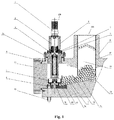
Fig. 1 is a front view of the unloading device according to an embodiment of the present application; -
Fig. 2 is a top view of the unloading device inFig. 1 according to an embodiment of the present application; -
Fig. 3 is a 3D structural diagram of a pressure-bearing casing assembly in the unloading device according to an embodiment of the present application; -
Fig. 4 is a structural schematic diagram of a shafting assembly in the unloading device according to an embodiment of the present application; -
Fig. 5 is a front view of a turntable assembly in the unloading device according to an embodiment of the present application; -
Fig. 6 is a structural schematic diagram of the bottom of a turntable assembly in the unloading device according to an embodiment of the present application; -
Fig. 7 is an axonometric diagram of a turntable assembly in the unloading device according to an embodiment of the present application; -
Fig. 8 is a structural diagram of a guard plate assembly in the unloading device according to an embodiment of the present application; and -
Fig. 9 is an installation diagram of a guard plate assembly and an insert bar assembly in the unloading device according to an embodiment of the present application. - In the drawings:
1 power mechanism 2 transmission mechanism 3 execution mechanism 4 pressure-bearing casing assembly 5 turntable assembly 6 guard plate assembly 7 disturbance mechanism 8 coupling support 9 first fastener 10 first sealing element 11 casing 12 lining cylinder 13 sphere outlet adapter pipe 14 end flange 15 bearing sleeve 16 unloading function area 17 stock bin 18 tapered surface chamber 19 vertical cylindrical cavity 20 reclaiming slot 21 connector 22 lower reclaiming portion 23 thrust bearing 24 withdrawal bearing bush 25 first bearing 26 second bearing 27 first shaft sleeve 28 second fastener 29 second shaft sleeve 30 third shaft sleeve 31 main shaft 32 upper auxiliary fence 33 middle main disturbance disk 34 scraper 35 reclaiming ring 36 spacer rib 37 inner baffle ring 38 arc- shaped surface 39 disturbance block 40 circular segment 41 tangent plane 42 bottom arc plate 43 insert bar assembly 44 material outlet 45 material guide bevel 46 bottom arc surface 47 top plane 48 material guide groove 49 positioning boss 50 insert bar 51 gantry 52 side baffle 53 reclaiming port 54 spherical material 55 direct-acting permanent magnet drive mechanism 100 driving line 200 hermetic space 300 shafting assembly - In order to make the objectives, technical solutions, and advantages of the embodiments of the present application clearer, the technical solutions of the embodiments of the present application will be clearly and completely described with reference to the accompanying drawings of the embodiments of the present application. Obviously, the described embodiments are part but not all of the embodiments of the present application. Based on the embodiments of the present application, all other embodiments obtained by a person of ordinary skill in the art without creative efforts shall fall within the protection scope of the present application.
- As shown in
Fig. 1 to Fig. 9 , the embodiments of the present application provide an unloading device, including a power mechanism 1, atransmission mechanism 2, anexecution mechanism 3, a pressure-bearingcasing assembly 4, aguard plate assembly 6 and adisturbance mechanism 7. - The power mechanism 1 includes a motor and a speed reducer connected to the motor.
- The
transmission mechanism 2 is a coupling. One end of thetransmission mechanism 2 is connected to the power mechanism 1, and the other end thereof is connected to theexecution mechanism 3. The power mechanism 1, thetransmission mechanism 2 and theexecution mechanism 3 are detachably connected in sequence to form avertical driving line 100. - The
execution mechanism 3 includes ashafting assembly 300 and aturntable assembly 5 connected in sequence from top to bottom. Theshafting assembly 300 is connected to theturntable assembly 5 through aconnector 21. - The pressure-bearing
casing assembly 4 includes acasing 11 and anend flange 14, abearing sleeve 15 that are respectively connected to thecasing 11. A bottom of thecasing 11 is provided with a sphereoutlet adapter pipe 13. - In a preferable embodiment, the
transmission mechanism 2 is a magnetic transmission. Acoupling support 8 is arranged outside thetransmission mechanism 2. Thecoupling support 8 is connected to the bearingsleeve 15 through afirst fastener 9. Afirst sealing element 10 is provided between thecoupling support 8 and the bearingsleeve 15 which is connected to the pressure-bearingcasing assembly 4. - An inner cavity of the pressure-bearing
casing assembly 4 is ahermetic space 200. The non-contact transmission characteristic of the magnetic transmission is used to convert the dynamic seal of theexecution mechanism 3 into a static seal to ensure zero atmosphere leakage in thehermetic space 200. - The
guard plate assembly 6 is installed in the pressure-bearingcasing assembly 4, and disposed below the drivingline 100, that is, theguard plate assembly 6 is disposed at the bottom of theturntable assembly 5. Theguard plate assembly 6 divides the inner cavity of thecasing 11 into two parts, namely astock bin 17 and anunloading function area 16.Spherical materials 54 are temporarily stored in a verticalcylindrical cavity 19 and atapered surface chamber 18. The area where the taperedsurface chamber 18 and theguard plate assembly 6 are connected is thestock bin 17. The unloadingfunction area 16 is a horizontal cylindrical chamber. Theturntable assembly 5 and theguard plate assembly 6 are located inside the unloadingfunction area 16 and collectively perform a singular unloading function. - The inner cavity of the
casing 11 of the pressure-bearingcasing assembly 4 includes anunloading function area 16, atapered surface chamber 18 and a verticalcylindrical cavity 19. Alining cylinder 12 is installed in the verticalcylindrical cavity 19. A lower portion of thelining cylinder 12 extends into the taperedsurface chamber 18, and the lower portion of thelining cylinder 12 is provided with a shovel-shaped cambered surface baffle. When thespherical materials 54 are filled in the verticalcylindrical cavity 19, due to the blocking effect of the shovel-shaped cambered surface baffle, and based on the principle of fluid pressure, the unloadingfunction area 16, the taperedsurface chamber 18 and the verticalcylindrical cavity 19 form a communicating vessel, and the pressure of the sphere column in the verticalcylindrical cavity 19 will push thespherical materials 54 to flow toward the taperedsurface chamber 18 and theunloading function area 16. Due to the blocking of theturntable assembly 5 and theguard plate assembly 6, the sphere flow forms a liquid-like free stacking surface at theunloading function area 16, and the height of the free stacking surface basically flushes with the bottom of the shovel-shaped cambered surface baffle. - In this embodiment, the
turntable assembly 5 includes an upperauxiliary fence 32, a middlemain disturbance disk 33, and alower reclaiming portion 22 that are arranged in sequence from top to bottom. The upperauxiliary fence 32, the middlemain disturbance disk 33, and thelower reclaiming portion 22 correspond to three layers of materials from bottom to top. - The
lower reclaiming portion 22 includes a reclaimingring 35 and aninner baffle ring 37 provided in the reclaimingring 35. The reclaimingring 35 includes a plurality ofspacer ribs 36 arranged annularly. The bottom of each of thespacer ribs 36 is connected to theinner baffle ring 37 through ascraper 34. Arc-shapedsurfaces 38 are provided at the reclaiming positions of theinner baffle ring 37. A reclaimingslot 20 is formed between each adjacent two of thespacer ribs 36 and theinner baffle ring 37. In this embodiment, two kinds of spacer ribs with different widths are used to introduce asymmetry to the reclaimingslot 20, so as to disturb the bottomspherical material 54. - A plurality of disturbance blocks 39 having irregular shapes are arranged on an outer surface of the middle
main disturbance disk 33 so as to disturb thespherical materials 54 of the middle layer in the height and diameter directions, thereby ensuring the reclaiming flexibility and reliability of thespherical materials 54 of the bottom layer. - An outer surface of the upper
auxiliary fence 32 is formed by smoothly transition-connecting severalcircular segments 40 andtangent planes 41. Thespherical materials 54 of the upper layer in thestock bin 17 is directly disturbed by this transitional fluctuant curved surface structure. - In this embodiment, the disturbance effects of the triple disturbance structure of the upper
auxiliary fence 32, the middlemain disturbance disk 33, and thelower reclaiming portion 22 on thespherical materials 54 in thestock bin 17 are integrated. Through the motion transmission, the flow of thespherical material 54 can be guaranteed uniform, which ensures the reliable reclaiming by the reclaimingslot 20. - In this embodiment, upon the pressure of the sphere column in the vertical
cylindrical cavity 19, the loosely accumulatedspherical materials 54 flow into thestock bin 17 through thelining cylinder 12. When the power mechanism 1 drives theexecution mechanism 3 to rotate through thetransmission mechanism 2, the pressure of the sphere column pushes thespherical materials 54 into the reclaimingslot 20 of theturntable assembly 5, so that thespherical materials 54 rotate, with themain disturbance disk 33, into the sphereoutlet adapter pipe 13, and thespherical materials 54 are discharged from the unloading device by gravity. - Since the
turntable assembly 5 has a plurality of reclaimingslots 20, theexecution mechanism 3 can take a plurality ofspherical materials 54 in each revolution, and then thespherical materials 54 are discharged into the sphereoutlet adapter pipe 13 through amaterial outlet 44 to complete the unloading operation of thespherical materials 54. However, due to the solid material characteristics of thespherical materials 54, and influence of the structures of theguard plate assembly 6, thecasing 11, thelining cylinder 12 and etc., influence of the material impacts such as the apparent shape of eachspherical material 54, damage fuel and debris, and influence of the torque, rotate speed and etc. of theexecution mechanism 3, it cannot be ensured that each reclaimingslot 20 can take aspherical material 54 when feeding is performed through thestock bin 17. In some cases, thespherical materials 54 may be temporarily squeezed, or are arched in thestock bin 17, so that thespherical materials 54 cannot enter the reclaimingslot 20. Frequent empty reclaiming of the reclaimingslot 20 will not only affect the unloading efficiency, but also is not beneficial to the automatic control of the reclaiming. Therefore, through the disturbance function of the three-layer functional sections of the upperauxiliary fence 32, the middlemain disturbance disk 33, and thelower reclaiming portion 22 provided in sequence from top to bottom of theturntable assembly 5, the problem of empty reclaiming of the material can be solved, thereby improving the sphere reclaiming rate. - The
guard plate assembly 6 includes abottom arc plate 42 and aninsert bar assembly 43 provided on thebottom arc plate 42. Thebottom arc plate 42 is connected to the taperedsurface chamber 18 through amaterial guide bevel 45, and theinsert bar assembly 43 is provided between thebottom arc plate 42 and thematerial guide bevel 45. - An upper surface of the
bottom arc plate 42 is atop plane 47, and a lower surface of thebottom arc plate 42 is abottom arc surface 46. Amaterial guide groove 48 is provided on thetop plane 47, and apositioning boss 49 is provided in thematerial guide groove 48. Thebottom arc plate 42 is mounted on the bottom of theunloading function area 16 of thecasing 11 through thepositioning boss 49, and thebottom arc surface 46 is attached with the unloadingfunction area 16 in an isodiametric manner. - The
insert bar assembly 43 includes agantry 51, twoinsert bars 50 correspondingly and movably connected to the left and right sides of thegantry 51 respectively, and two side baffles 52 symmetrically disposed on the left and right sides of thegantry 51. Thegantry 51 is provided with a reclaimingport 53. In this embodiment, insert pins of eachinsert bar 50 can be movably connected to thegantry 51 by penetrating the side plates of thegantry 51. The relative movement of the twoinsert bars 50 can close the reclaimingport 53, and the opposite movement of the twoinsert bars 50 can open the reclaimingport 53. The two side baffles 52 are provided in a tapered shape. Thematerial guide bevel 45, the two side baffles 52, the reclaimingport 53 and thebottom arc plate 42 together form a reclaiming material path for theturntable assembly 5, and thematerial guide groove 48 on thebottom arc plate 42 can ensure the smooth flow of thespherical materials 54, dust and etc. under be guide of the reclaimingslot 20 and thescraper 34. Thepositioning boss 49 facilitates the installation of theguard plate assembly 6 and can limit theturntable assembly 5 at the same time. Thegantry 51 and thebottom arc plate 42 can effectively block three or more layers of thespherical material 54 in thestock bin 17 without forming an additional pressing load against theturntable assembly 5. - When the
turntable assembly 5 fails to discharge spheres for a long time, it can be determined through control logic that thestock bin 17 is arched. Due to the structural characteristics of thespherical material 54 and thestock bin 17, the arching phenomenon may occur in three positions: a position near the shovel-shaped cambered surface baffle of thelining cylinder 12, a possibly formed arching in the height direction at thegantry 51 of theinsert bar assembly 43 when thespherical material 54 accumulated in thestock bin 17 exceeds the upperauxiliary fence 32, and the circumferential arc length on thebottom arc plate 42 near the reclaimingport 53. - The occurrence probability of the above-mentioned three types of bridging increases in order. In order to remove the bridging so as to ensure the normal unloading of the core, the
disturbance mechanism 7 is used in this embodiment to solve the problem. Thedisturbance mechanism 7 includes an electromagneticallydrive push rod 7a and anelectromagnetically drive mechanism 7b. As a linear drive mechanism, the electromagneticallydrive push rod 7a can solve the problem of arch breakage in the case of the first bridging. For the second and third bridging, the bridge can be broken by theelectromagnetically drive mechanism 7b. - It's assumed that the turntable assembly in this embodiment is provided with ten reclaiming
slots 20, and onespherical material 54 is reclaimed for an average of 20 seconds. According to this sphere reclaiming probability, if the counter provided downstream of the unloading device fails to reclaim thespherical materials 54 within 2 consecutive minutes, it can be determined that the third or the second bridging may occur. Therefore, theelectromagnetically drive mechanism 7b is firstly started to break the bridge. If thespherical material 54 is still not reclaimed, it is determined that the first bridging may occur, and at this time, the electromagneticallydrive push rod 7a may be started to break the bridge. - In this embodiment, the bearing
sleeve 15 of the pressure-bearingcasing 4 is connected to thecasing 11. - The shafting
assembly 300 in theexecution mechanism 3 includes amain shaft 31, afirst bearing 25, asecond bearing 26, awithdrawal bearing bush 24, and a thrust bearing 23. Thefirst bearing 25 and thesecond bearing 26 are respectively installed on themain shaft 31 from top to bottom. Thefirst bearing 25 and thesecond bearing 26 are spaced by asecond shaft sleeve 29 and athird shaft sleeve 30, and thefirst bearing 25 and thesecond bearing 26 are both disposed in thewithdrawal bearing bush 24. The thrust bearing 23 is mounted on themain shaft 31 and disposed at an upper part of thewithdrawal bearing bush 24. A bottom surface of the thrust bearing 23 abuts against thefirst shaft sleeve 27, and the thrust bearing 23 bears against thefirst bearing 25 through thefirst shaft sleeve 27. Thewithdrawal bearing bush 24 is installed in the bearingsleeve 15 through asecond fastener 28. - In this embodiment, the thrust bearing 23 mainly bears the self-weight load of the shafting
assembly 300. Thefirst bearing 25 and thesecond bearing 26 play an auxiliary supporting role on the shaftingassembly 300, and bear the torque generated by the pressing force and friction force of the pebble bed in thestock bin 17. Thefirst bearing 25, thesecond bearing 26 and the thrust bearing 23 jointly ensure the operational stability of the shaftingassembly 300. - Since the
first bearing 25 and thesecond bearing 26 are both placed in thewithdrawal bearing bush 24, after the uppermost thrust bearing 23 is disassembled, thefirst bearing 25 and thesecond bearing 26 can be easily disassembled and assembled with a puller by disassembling and assembling thewithdrawal bearing bush 24. The replacement and maintenance are simple, and no special tooling is required. - In this embodiment, two direct-acting permanent
magnet drive mechanisms 55 are also provided. The two direct-acting permanentmagnet drive mechanisms 55 respectively push the twoinsert bars 50 to close thegantry 51 so as to block the radioactivespherical materials 54 in thestock bin 17, thereby integrally disassembling the shaftingassembly 300 and theturntable assembly 5 for maintenance and replacement by extracting the bearingsleeve 15. - In summary, the unloading device described in the embodiments of the present application can fully disturb the spherical materials in the stock bin in the circumferential, radial, and height directions, achieve the adaptive and efficient reclaiming, and ensure the reclaiming reliability of the spherical materials and the stability of the sphere flow unloading.
- In the description of the present application, it should be noted that, the terms "connected with" and "connected to" should be understood in a broad sense unless otherwise specified and limited, for example, they may be fixed connections, detachable connections, or integrated connections; they can be mechanical connections or electrical connections; they can be direct connections or indirect connections through intermediate mediums. For those of ordinary skill in the art, the specific meanings of the above terms in this application can be understood according to specific situations.
- In the description of the present application, unless otherwise stated, "several" means one or more; "multiple" means two or more. The orientation or position relations indicated by the terms "upper", "lower", "left", "right", "inner", "outer" and etc. are based on the orientation or position relations shown in the drawings, and are only for the convenience of describing the present application and simplifying the description, rather than indicating or implying that the referred device or element must have a specific orientation, be constructed and operated in a specific orientation, and therefore cannot be understood as limiting the present application.
- Finally, it should be noted that the embodiments above are only used to illustrate rather than limit the technical solutions of the present application. Although the present application has been described in detail with reference to the foregoing embodiments, those of ordinary skills in the art should understand that they can still modify the technical solutions described in the various embodiments above, or equivalently replace some of the technical features thereof; and these modifications or replacements do not depart the essence of the corresponding solutions from the spirit and scope of the technical solutions of the various embodiments of the present application.
Claims (10)
- An unloading device, comprising a power mechanism, a transmission mechanism, and an execution mechanism that are connected in sequence from top to bottom; wherein the execution mechanism comprises a shafting assembly and a turntable assembly that are connected in sequence from top to bottom; wherein the turntable assembly comprises an upper auxiliary fence, a middle main disturbance disk, and a lower reclaiming portion that are arranged in sequence from top to bottom.
- The unloading device of claim 1, characterized in that a bottom of the turntable assembly is provided with a guard plate assembly.
- The unloading device of claim 2, characterized in that the guard plate assembly comprises a bottom arc plate and an insert bar assembly provided on the bottom arc plate; the bottom arc plate is connected to a tapered surface chamber, and the insert bar assembly is arranged between the bottom arc plate and the tapered surface chamber.
- The unloading device of claim 3, characterized in that the insert bar assembly comprises a gantry, two insert bars correspondingly and movably connected to left and right sides of the gantry respectively, and two side baffles symmetrically disposed on the left and right sides of the gantry; the gantry is provided with a reclaiming port.
- The unloading device of claim 1, characterized in that the lower reclaiming portion comprises a reclaiming ring and an inner baffle ring provided in the reclaiming ring; the reclaiming ring comprises a plurality of spacer ribs arranged annularly, and each of the spacer ribs is connected to the inner baffle ring; a reclaiming slot is formed between each adjacent two of the spacer ribs and the inner baffle ring.
- The unloading device of claim 1, characterized in that a plurality of disturbance blocks are provided on an outer side surface of the middle main disturbance disk.
- The unloading device of claim 1, characterized in that the upper auxiliary fence is formed by circular segments and tangent planes that are arranged at intervals.
- The unloading device of claim 1, characterized in that the shafting assembly comprises a main shaft, a first bearing, a second bearing, a withdrawal bearing bush, and a thrust bearing; the first bearing and the second bearing are respectively installed on the main shaft from top to bottom; the first bearing and the second bearing are both arranged in the withdrawal bearing bush; the thrust bearing is mounted on the main shaft and arranged on an upper portion of the withdrawal bearing bush.
- The unloading device of claim 1, characterized in that the device further comprises a pressure-bearing casing assembly; an upper end and a lower end of the transmission mechanism are detachably connected to the power mechanism and the execution mechanism respectively; a coupling support is arranged outside the transmission mechanism, and the coupling support is connected to a bearing sleeve connected to the pressure-bearing casing assembly.
- The unloading device of claim 9, characterized in that disturbance mechanisms are provided on the pressure-bearing casing assembly, and the disturbance mechanisms are linear reciprocating drive mechanisms.
Applications Claiming Priority (2)
| Application Number | Priority Date | Filing Date | Title |
|---|---|---|---|
| CN201811633899.5A CN109607240B (en) | 2018-12-29 | 2018-12-29 | Discharging device |
| PCT/CN2019/098591 WO2020134074A1 (en) | 2018-12-29 | 2019-07-31 | Unloading device |
Publications (4)
| Publication Number | Publication Date |
|---|---|
| EP3865433A1 true EP3865433A1 (en) | 2021-08-18 |
| EP3865433A4 EP3865433A4 (en) | 2022-01-19 |
| EP3865433C0 EP3865433C0 (en) | 2024-05-29 |
| EP3865433B1 EP3865433B1 (en) | 2024-05-29 |
Family
ID=66016271
Family Applications (1)
| Application Number | Title | Priority Date | Filing Date |
|---|---|---|---|
| EP19905652.4A Active EP3865433B1 (en) | 2018-12-29 | 2019-07-31 | Unloading device |
Country Status (9)
| Country | Link |
|---|---|
| US (1) | US11978566B2 (en) |
| EP (1) | EP3865433B1 (en) |
| JP (1) | JP6969010B2 (en) |
| KR (1) | KR102409231B1 (en) |
| CN (1) | CN109607240B (en) |
| MY (1) | MY207924A (en) |
| RU (1) | RU2753255C1 (en) |
| WO (1) | WO2020134074A1 (en) |
| ZA (1) | ZA202007779B (en) |
Families Citing this family (5)
| Publication number | Priority date | Publication date | Assignee | Title |
|---|---|---|---|---|
| CN109607240B (en) | 2018-12-29 | 2020-02-11 | 清华大学 | Discharging device |
| CN113488210B (en) * | 2021-06-01 | 2022-10-14 | 华能山东石岛湾核电有限公司 | Rotating disc type ball conveying device and method and ball bed type high-temperature gas cooled reactor |
| CN115050498B (en) * | 2022-06-27 | 2024-01-30 | 华能山东石岛湾核电有限公司 | Reciprocating type choke of high-temperature gas cooled reactor fuel loading and unloading system |
| CN116313192A (en) * | 2023-03-22 | 2023-06-23 | 华能核能技术研究院有限公司 | Pebble bed reactor fuel pellet unloading device and reactor |
| CN117275768B (en) * | 2023-09-01 | 2024-08-23 | 华能核能技术研究院有限公司 | Passive unloading shutdown device of pebble-bed reactor |
Family Cites Families (36)
| Publication number | Priority date | Publication date | Assignee | Title |
|---|---|---|---|---|
| GB923546A (en) * | 1958-07-26 | 1963-04-10 | Heraeus Gmbh W C | Improvements in or relating to an apparatus for extracting individual spherical objects from a large stock thereof |
| GB958439A (en) | 1962-05-30 | 1964-05-21 | Atomic Energy Authority Uk | Improvements in or relating to pressurised nuclear reactors |
| US4058671A (en) | 1975-04-07 | 1977-11-15 | International Telephone And Telegraph Corporation | Electrical penetration assembly |
| SE468167B (en) * | 1991-03-18 | 1992-11-16 | Kamyr Ab | DEVICE FOR EXHAUSTION OF PARTICULATE MATERIAL |
| NL9100542A (en) * | 1991-03-27 | 1992-10-16 | Henricus Christianus Antonius | CONTAINER FOR DELIVERY OF SOIL COMPOST IN THIN LAYER. |
| AU3111900A (en) | 1998-12-04 | 2000-06-19 | Cidra Corporation | Pressure-isolated bragg grating temperature sensor |
| WO2003096030A2 (en) | 2002-05-13 | 2003-11-20 | Pebble Bed Modular Reactor (Proprietary) Limited | A method of discharging spherical elements from a container and a dispensing apparatus |
| JP4152372B2 (en) * | 2004-10-05 | 2008-09-17 | 大盛工業株式会社 | Powder supply measurement method |
| JP2007209102A (en) | 2006-02-01 | 2007-08-16 | Toshiba Corp | Electric penetration assembly, and its manufacturing method |
| CN101324498B (en) * | 2008-07-17 | 2011-01-12 | 吉林江北机械制造有限责任公司 | Steel ball automatic sorting machines thereof |
| CN101770825B (en) * | 2009-12-25 | 2012-07-25 | 清华大学 | Integrated discharging device for high-temperature gas-cooled reactor |
| JP5714263B2 (en) * | 2010-08-13 | 2015-05-07 | 株式会社アイシンナノテクノロジーズ | Quantitative feeder for granular material |
| CN202221489U (en) | 2011-08-17 | 2012-05-16 | 中国核动力研究设计院 | Reactor containment optical fiber electrical penetration assembly |
| CN202221488U (en) | 2011-08-17 | 2012-05-16 | 中国核动力研究设计院 | Optical fiber feedthrough assembly for connecting a nuclear reactor safety shell optical path |
| CN102750996B (en) | 2012-06-29 | 2013-05-01 | 清华大学 | Grouped pneumatic lifting system and method for pebble-bed reactor fuel elements |
| CN102855951B (en) * | 2012-09-27 | 2015-04-22 | 清华大学 | Loading and temporary storage device for new fuel of pebble-bed high-temperature reactor |
| CN102881343B (en) | 2012-09-29 | 2015-03-04 | 清华大学 | Temporary storage device for discharged spent fuel of pebble-bed high-temperature reactor |
| CN202939981U (en) | 2012-11-20 | 2013-05-15 | 安徽省鑫源达有色金属材料有限公司 | Replaceable glass sealed electrical penetration assembly component |
| CN102982855B (en) * | 2012-12-20 | 2015-04-15 | 清华大学 | Device for isolating and conveying fuel spheres of sphere bed high temperature reactor |
| CN203529425U (en) * | 2013-10-27 | 2014-04-09 | 惠水县昶达数控有限公司 | Device for feeding spherical stone or glass work products with threading holes |
| CN103708728B (en) | 2013-11-26 | 2015-10-28 | 清华大学 | A kind of Glass-metal seal material for high temperature gas cooled reactor electrical penetration and preparation method thereof |
| CN103971772B (en) * | 2014-01-03 | 2016-07-06 | 中国科学院上海应用物理研究所 | Device for discharging and discharge method for pebble bed reactor fuel sphere |
| JP6456718B2 (en) * | 2015-02-19 | 2019-01-23 | 株式会社Fdkエンジニアリング | Spherical parts feeder |
| FR3038444B1 (en) | 2015-06-30 | 2017-08-11 | Soc Technique Pour L'energie Atomique | ASSEMBLY OF ELECTRIC PENETRATION OF TANK OF A NUCLEAR REACTOR |
| JP6754571B2 (en) * | 2015-12-28 | 2020-09-16 | 倉敷紡績株式会社 | Goods supply device |
| CN205289018U (en) * | 2016-01-12 | 2016-06-08 | 湖北工业大学 | Multistage sorting unit of steel ball |
| KR101868615B1 (en) * | 2016-01-29 | 2018-06-18 | 이석정 | Variant product weight classification system |
| CN105845186B (en) | 2016-03-30 | 2018-05-29 | 清华大学 | The preparation method of pressure power electrical penetration in a kind of high temperature gas cooled reactor |
| CN206798673U (en) * | 2017-03-28 | 2017-12-26 | 东莞铭衡智能科技股份有限公司 | A kind of steel ball cutting agency |
| CN107817061B (en) | 2017-09-06 | 2019-12-31 | 天津大学 | Packaging process method of new FBG temperature sensor based on low melting point glass |
| CN207844404U (en) * | 2018-02-08 | 2018-09-11 | 广州丽高塑料制品有限公司 | A kind of foam pump ball automatic blanking device |
| CN108706335A (en) * | 2018-06-11 | 2018-10-26 | 上海松川远亿机械设备有限公司 | Charging collating unit for bulk granular material packaging |
| CN108831571B (en) | 2018-06-22 | 2020-06-05 | 清华大学 | Electrical penetration and its manufacturing method, electrical penetration device |
| CN109607240B (en) * | 2018-12-29 | 2020-02-11 | 清华大学 | Discharging device |
| CN109616235B (en) * | 2018-12-29 | 2020-05-05 | 清华大学 | Temporary discharging storage device |
| CN109785985B (en) * | 2018-12-30 | 2020-09-15 | 清华大学 | Spherical element detects positioner |
-
2018
- 2018-12-29 CN CN201811633899.5A patent/CN109607240B/en active Active
-
2019
- 2019-07-31 US US17/045,076 patent/US11978566B2/en active Active
- 2019-07-31 KR KR1020207015554A patent/KR102409231B1/en active Active
- 2019-07-31 WO PCT/CN2019/098591 patent/WO2020134074A1/en not_active Ceased
- 2019-07-31 MY MYPI2021000387A patent/MY207924A/en unknown
- 2019-07-31 RU RU2020141384A patent/RU2753255C1/en active
- 2019-07-31 EP EP19905652.4A patent/EP3865433B1/en active Active
- 2019-07-31 JP JP2020545306A patent/JP6969010B2/en active Active
-
2020
- 2020-12-14 ZA ZA2020/07779A patent/ZA202007779B/en unknown
Also Published As
| Publication number | Publication date |
|---|---|
| US11978566B2 (en) | 2024-05-07 |
| CN109607240A (en) | 2019-04-12 |
| MY207924A (en) | 2025-03-27 |
| CN109607240B (en) | 2020-02-11 |
| KR20200083546A (en) | 2020-07-08 |
| JP6969010B2 (en) | 2021-11-24 |
| RU2753255C1 (en) | 2021-08-12 |
| ZA202007779B (en) | 2022-04-28 |
| US20210151210A1 (en) | 2021-05-20 |
| EP3865433A4 (en) | 2022-01-19 |
| WO2020134074A1 (en) | 2020-07-02 |
| JP2021520327A (en) | 2021-08-19 |
| KR102409231B1 (en) | 2022-06-15 |
| EP3865433C0 (en) | 2024-05-29 |
| EP3865433B1 (en) | 2024-05-29 |
Similar Documents
| Publication | Publication Date | Title |
|---|---|---|
| US11978566B2 (en) | Unloading device | |
| US11887740B2 (en) | Unloading and temporary storage device | |
| CN102982855B (en) | Device for isolating and conveying fuel spheres of sphere bed high temperature reactor | |
| CN102881343A (en) | Temporary storage device for discharged spent fuel of pebble-bed high-temperature reactor | |
| CN110148482A (en) | An escalator type fuel transfer device | |
| EP3404266A1 (en) | Primary circulating pump assembly | |
| US5549459A (en) | Radial bearing assembly for a high intertia flywheel of a canned motor pump | |
| CN217606563U (en) | Ball passing flow blocking device with ball clamping fault online removing function and gas cooled reactor | |
| CN115069560B (en) | Binary channels piece separation flow resistor | |
| JPH0368437A (en) | Mixer | |
| CN214671848U (en) | Spiral reverse rotation vertical lifting device for spherical fuel | |
| RU2190127C2 (en) | Pump for transferring liquid in high-pressure circuit | |
| CN218095406U (en) | A shaft structure for convenient inspection and maintenance of the gas storage chamber of the gravity compressed air energy storage system | |
| CN216768349U (en) | Self-locking prevention mechanical sealing structure | |
| US3341423A (en) | Handling device for nuclear reactor refuelling facility | |
| CN113241205B (en) | A spherical fuel spiral reverse rotation vertical lifting device | |
| CN217606564U (en) | Flow plug | |
| CA2945750C (en) | Method of extracting plug and removable unit when refueling nuclear reactor | |
| KR20130140008A (en) | Device and method for replacing an irradiated fuel assembly with a new fuel assembly in the vessel of a nuclear reactor, and nuclear reactor including such a device | |
| CN117275768B (en) | Passive unloading shutdown device of pebble-bed reactor | |
| RU2811086C1 (en) | Suction device for high temperature gas cooled reactor | |
| US3205142A (en) | Charging apparatus for nuclear reactors | |
| CN220354054U (en) | Rotary locking type inner core integrated multistage pump without main pressure-bearing stud | |
| Hennings | Fuel handling system for core elements of a pebble-bed reactor | |
| CN218005972U (en) | Gravity compressed air energy storage system with compressed air diversion piece |
Legal Events
| Date | Code | Title | Description |
|---|---|---|---|
| STAA | Information on the status of an ep patent application or granted ep patent |
Free format text: STATUS: THE INTERNATIONAL PUBLICATION HAS BEEN MADE |
|
| PUAI | Public reference made under article 153(3) epc to a published international application that has entered the european phase |
Free format text: ORIGINAL CODE: 0009012 |
|
| STAA | Information on the status of an ep patent application or granted ep patent |
Free format text: STATUS: REQUEST FOR EXAMINATION WAS MADE |
|
| 17P | Request for examination filed |
Effective date: 20210113 |
|
| AK | Designated contracting states |
Kind code of ref document: A1 Designated state(s): AL AT BE BG CH CY CZ DE DK EE ES FI FR GB GR HR HU IE IS IT LI LT LU LV MC MK MT NL NO PL PT RO RS SE SI SK SM TR |
|
| A4 | Supplementary search report drawn up and despatched |
Effective date: 20211217 |
|
| RIC1 | Information provided on ipc code assigned before grant |
Ipc: G21C 19/19 20060101ALI20211213BHEP Ipc: B65G 65/48 20060101AFI20211213BHEP |
|
| DAV | Request for validation of the european patent (deleted) | ||
| DAX | Request for extension of the european patent (deleted) | ||
| RAP1 | Party data changed (applicant data changed or rights of an application transferred) |
Owner name: CHINERGY CO., LTD. |
|
| GRAP | Despatch of communication of intention to grant a patent |
Free format text: ORIGINAL CODE: EPIDOSNIGR1 |
|
| STAA | Information on the status of an ep patent application or granted ep patent |
Free format text: STATUS: GRANT OF PATENT IS INTENDED |
|
| RIC1 | Information provided on ipc code assigned before grant |
Ipc: G21C 19/19 20060101ALI20231207BHEP Ipc: B65G 65/48 20060101AFI20231207BHEP |
|
| INTG | Intention to grant announced |
Effective date: 20240103 |
|
| GRAS | Grant fee paid |
Free format text: ORIGINAL CODE: EPIDOSNIGR3 |
|
| GRAA | (expected) grant |
Free format text: ORIGINAL CODE: 0009210 |
|
| STAA | Information on the status of an ep patent application or granted ep patent |
Free format text: STATUS: THE PATENT HAS BEEN GRANTED |
|
| AK | Designated contracting states |
Kind code of ref document: B1 Designated state(s): AL AT BE BG CH CY CZ DE DK EE ES FI FR GB GR HR HU IE IS IT LI LT LU LV MC MK MT NL NO PL PT RO RS SE SI SK SM TR |
|
| REG | Reference to a national code |
Ref country code: CH Ref legal event code: EP |
|
| REG | Reference to a national code |
Ref country code: IE Ref legal event code: FG4D |
|
| REG | Reference to a national code |
Ref country code: DE Ref legal event code: R096 Ref document number: 602019053090 Country of ref document: DE |
|
| U01 | Request for unitary effect filed |
Effective date: 20240626 |
|
| U07 | Unitary effect registered |
Designated state(s): AT BE BG DE DK EE FI FR IT LT LU LV MT NL PT SE SI Effective date: 20240705 |
|
| U20 | Renewal fee for the european patent with unitary effect paid |
Year of fee payment: 6 Effective date: 20240726 |
|
| PG25 | Lapsed in a contracting state [announced via postgrant information from national office to epo] |
Ref country code: IS Free format text: LAPSE BECAUSE OF FAILURE TO SUBMIT A TRANSLATION OF THE DESCRIPTION OR TO PAY THE FEE WITHIN THE PRESCRIBED TIME-LIMIT Effective date: 20240929 |
|
| PG25 | Lapsed in a contracting state [announced via postgrant information from national office to epo] |
Ref country code: HR Free format text: LAPSE BECAUSE OF FAILURE TO SUBMIT A TRANSLATION OF THE DESCRIPTION OR TO PAY THE FEE WITHIN THE PRESCRIBED TIME-LIMIT Effective date: 20240529 |
|
| PG25 | Lapsed in a contracting state [announced via postgrant information from national office to epo] |
Ref country code: GR Free format text: LAPSE BECAUSE OF FAILURE TO SUBMIT A TRANSLATION OF THE DESCRIPTION OR TO PAY THE FEE WITHIN THE PRESCRIBED TIME-LIMIT Effective date: 20240830 |
|
| PG25 | Lapsed in a contracting state [announced via postgrant information from national office to epo] |
Ref country code: ES Free format text: LAPSE BECAUSE OF FAILURE TO SUBMIT A TRANSLATION OF THE DESCRIPTION OR TO PAY THE FEE WITHIN THE PRESCRIBED TIME-LIMIT Effective date: 20240529 |
|
| PG25 | Lapsed in a contracting state [announced via postgrant information from national office to epo] |
Ref country code: PL Free format text: LAPSE BECAUSE OF FAILURE TO SUBMIT A TRANSLATION OF THE DESCRIPTION OR TO PAY THE FEE WITHIN THE PRESCRIBED TIME-LIMIT Effective date: 20240529 |
|
| PG25 | Lapsed in a contracting state [announced via postgrant information from national office to epo] |
Ref country code: PL Free format text: LAPSE BECAUSE OF FAILURE TO SUBMIT A TRANSLATION OF THE DESCRIPTION OR TO PAY THE FEE WITHIN THE PRESCRIBED TIME-LIMIT Effective date: 20240529 Ref country code: NO Free format text: LAPSE BECAUSE OF FAILURE TO SUBMIT A TRANSLATION OF THE DESCRIPTION OR TO PAY THE FEE WITHIN THE PRESCRIBED TIME-LIMIT Effective date: 20240829 Ref country code: IS Free format text: LAPSE BECAUSE OF FAILURE TO SUBMIT A TRANSLATION OF THE DESCRIPTION OR TO PAY THE FEE WITHIN THE PRESCRIBED TIME-LIMIT Effective date: 20240929 Ref country code: HR Free format text: LAPSE BECAUSE OF FAILURE TO SUBMIT A TRANSLATION OF THE DESCRIPTION OR TO PAY THE FEE WITHIN THE PRESCRIBED TIME-LIMIT Effective date: 20240529 Ref country code: GR Free format text: LAPSE BECAUSE OF FAILURE TO SUBMIT A TRANSLATION OF THE DESCRIPTION OR TO PAY THE FEE WITHIN THE PRESCRIBED TIME-LIMIT Effective date: 20240830 Ref country code: ES Free format text: LAPSE BECAUSE OF FAILURE TO SUBMIT A TRANSLATION OF THE DESCRIPTION OR TO PAY THE FEE WITHIN THE PRESCRIBED TIME-LIMIT Effective date: 20240529 Ref country code: RS Free format text: LAPSE BECAUSE OF FAILURE TO SUBMIT A TRANSLATION OF THE DESCRIPTION OR TO PAY THE FEE WITHIN THE PRESCRIBED TIME-LIMIT Effective date: 20240829 |
|
| PG25 | Lapsed in a contracting state [announced via postgrant information from national office to epo] |
Ref country code: CZ Free format text: LAPSE BECAUSE OF FAILURE TO SUBMIT A TRANSLATION OF THE DESCRIPTION OR TO PAY THE FEE WITHIN THE PRESCRIBED TIME-LIMIT Effective date: 20240529 |
|
| PG25 | Lapsed in a contracting state [announced via postgrant information from national office to epo] |
Ref country code: RO Free format text: LAPSE BECAUSE OF FAILURE TO SUBMIT A TRANSLATION OF THE DESCRIPTION OR TO PAY THE FEE WITHIN THE PRESCRIBED TIME-LIMIT Effective date: 20240529 Ref country code: SK Free format text: LAPSE BECAUSE OF FAILURE TO SUBMIT A TRANSLATION OF THE DESCRIPTION OR TO PAY THE FEE WITHIN THE PRESCRIBED TIME-LIMIT Effective date: 20240529 |
|
| PG25 | Lapsed in a contracting state [announced via postgrant information from national office to epo] |
Ref country code: SM Free format text: LAPSE BECAUSE OF FAILURE TO SUBMIT A TRANSLATION OF THE DESCRIPTION OR TO PAY THE FEE WITHIN THE PRESCRIBED TIME-LIMIT Effective date: 20240529 |
|
| PG25 | Lapsed in a contracting state [announced via postgrant information from national office to epo] |
Ref country code: SM Free format text: LAPSE BECAUSE OF FAILURE TO SUBMIT A TRANSLATION OF THE DESCRIPTION OR TO PAY THE FEE WITHIN THE PRESCRIBED TIME-LIMIT Effective date: 20240529 Ref country code: SK Free format text: LAPSE BECAUSE OF FAILURE TO SUBMIT A TRANSLATION OF THE DESCRIPTION OR TO PAY THE FEE WITHIN THE PRESCRIBED TIME-LIMIT Effective date: 20240529 Ref country code: RO Free format text: LAPSE BECAUSE OF FAILURE TO SUBMIT A TRANSLATION OF THE DESCRIPTION OR TO PAY THE FEE WITHIN THE PRESCRIBED TIME-LIMIT Effective date: 20240529 Ref country code: CZ Free format text: LAPSE BECAUSE OF FAILURE TO SUBMIT A TRANSLATION OF THE DESCRIPTION OR TO PAY THE FEE WITHIN THE PRESCRIBED TIME-LIMIT Effective date: 20240529 |
|
| PG25 | Lapsed in a contracting state [announced via postgrant information from national office to epo] |
Ref country code: MC Free format text: LAPSE BECAUSE OF FAILURE TO SUBMIT A TRANSLATION OF THE DESCRIPTION OR TO PAY THE FEE WITHIN THE PRESCRIBED TIME-LIMIT Effective date: 20240529 |
|
| REG | Reference to a national code |
Ref country code: CH Ref legal event code: PL |
|
| PLBE | No opposition filed within time limit |
Free format text: ORIGINAL CODE: 0009261 |
|
| STAA | Information on the status of an ep patent application or granted ep patent |
Free format text: STATUS: NO OPPOSITION FILED WITHIN TIME LIMIT |
|
| GBPC | Gb: european patent ceased through non-payment of renewal fee |
Effective date: 20240829 |
|
| PG25 | Lapsed in a contracting state [announced via postgrant information from national office to epo] |
Ref country code: CH Free format text: LAPSE BECAUSE OF NON-PAYMENT OF DUE FEES Effective date: 20240731 |
|
| 26N | No opposition filed |
Effective date: 20250303 |
|
| PG25 | Lapsed in a contracting state [announced via postgrant information from national office to epo] |
Ref country code: GB Free format text: LAPSE BECAUSE OF NON-PAYMENT OF DUE FEES Effective date: 20240829 |
|
| PG25 | Lapsed in a contracting state [announced via postgrant information from national office to epo] |
Ref country code: IE Free format text: LAPSE BECAUSE OF NON-PAYMENT OF DUE FEES Effective date: 20240731 |
|
| U20 | Renewal fee for the european patent with unitary effect paid |
Year of fee payment: 7 Effective date: 20250721 |
|
| PG25 | Lapsed in a contracting state [announced via postgrant information from national office to epo] |
Ref country code: CY Free format text: LAPSE BECAUSE OF FAILURE TO SUBMIT A TRANSLATION OF THE DESCRIPTION OR TO PAY THE FEE WITHIN THE PRESCRIBED TIME-LIMIT; INVALID AB INITIO Effective date: 20190731 |
|
| PG25 | Lapsed in a contracting state [announced via postgrant information from national office to epo] |
Ref country code: HU Free format text: LAPSE BECAUSE OF FAILURE TO SUBMIT A TRANSLATION OF THE DESCRIPTION OR TO PAY THE FEE WITHIN THE PRESCRIBED TIME-LIMIT; INVALID AB INITIO Effective date: 20190731 |