EP3865397B1 - Procédés et assemblages de panneaux dérivantes de liquide - Google Patents
Procédés et assemblages de panneaux dérivantes de liquide Download PDFInfo
- Publication number
- EP3865397B1 EP3865397B1 EP21156387.9A EP21156387A EP3865397B1 EP 3865397 B1 EP3865397 B1 EP 3865397B1 EP 21156387 A EP21156387 A EP 21156387A EP 3865397 B1 EP3865397 B1 EP 3865397B1
- Authority
- EP
- European Patent Office
- Prior art keywords
- flow
- panel assembly
- wettability
- liquid
- director elements
- Prior art date
- Legal status (The legal status is an assumption and is not a legal conclusion. Google has not performed a legal analysis and makes no representation as to the accuracy of the status listed.)
- Active
Links
Images


Classifications
-
- B—PERFORMING OPERATIONS; TRANSPORTING
- B64—AIRCRAFT; AVIATION; COSMONAUTICS
- B64C—AEROPLANES; HELICOPTERS
- B64C1/00—Fuselages; Constructional features common to fuselages, wings, stabilising surfaces or the like
- B64C1/06—Frames; Stringers; Longerons ; Fuselage sections
- B64C1/10—Bulkheads
-
- B—PERFORMING OPERATIONS; TRANSPORTING
- B64—AIRCRAFT; AVIATION; COSMONAUTICS
- B64C—AEROPLANES; HELICOPTERS
- B64C1/00—Fuselages; Constructional features common to fuselages, wings, stabilising surfaces or the like
- B64C1/06—Frames; Stringers; Longerons ; Fuselage sections
- B64C1/12—Construction or attachment of skin panels
-
- B—PERFORMING OPERATIONS; TRANSPORTING
- B32—LAYERED PRODUCTS
- B32B—LAYERED PRODUCTS, i.e. PRODUCTS BUILT-UP OF STRATA OF FLAT OR NON-FLAT, e.g. CELLULAR OR HONEYCOMB, FORM
- B32B3/00—Layered products comprising a layer with external or internal discontinuities or unevennesses, or a layer of non-planar shape; Layered products comprising a layer having particular features of form
- B32B3/26—Layered products comprising a layer with external or internal discontinuities or unevennesses, or a layer of non-planar shape; Layered products comprising a layer having particular features of form characterised by a particular shape of the outline of the cross-section of a continuous layer; characterised by a layer with cavities or internal voids ; characterised by an apertured layer
- B32B3/30—Layered products comprising a layer with external or internal discontinuities or unevennesses, or a layer of non-planar shape; Layered products comprising a layer having particular features of form characterised by a particular shape of the outline of the cross-section of a continuous layer; characterised by a layer with cavities or internal voids ; characterised by an apertured layer characterised by a layer formed with recesses or projections, e.g. hollows, grooves, protuberances, ribs
-
- B—PERFORMING OPERATIONS; TRANSPORTING
- B64—AIRCRAFT; AVIATION; COSMONAUTICS
- B64C—AEROPLANES; HELICOPTERS
- B64C1/00—Fuselages; Constructional features common to fuselages, wings, stabilising surfaces or the like
- B64C1/06—Frames; Stringers; Longerons ; Fuselage sections
- B64C1/066—Interior liners
- B64C1/067—Interior liners comprising means for preventing icing or condensation conditions
-
- B—PERFORMING OPERATIONS; TRANSPORTING
- B64—AIRCRAFT; AVIATION; COSMONAUTICS
- B64C—AEROPLANES; HELICOPTERS
- B64C1/00—Fuselages; Constructional features common to fuselages, wings, stabilising surfaces or the like
- B64C1/14—Windows; Doors; Hatch covers or access panels; Surrounding frame structures; Canopies; Windscreens accessories therefor, e.g. pressure sensors, water deflectors, hinges, seals, handles, latches, windscreen wipers
-
- F—MECHANICAL ENGINEERING; LIGHTING; HEATING; WEAPONS; BLASTING
- F28—HEAT EXCHANGE IN GENERAL
- F28B—STEAM OR VAPOUR CONDENSERS
- F28B9/00—Auxiliary systems, arrangements, or devices
- F28B9/08—Auxiliary systems, arrangements, or devices for collecting and removing condensate
-
- B—PERFORMING OPERATIONS; TRANSPORTING
- B32—LAYERED PRODUCTS
- B32B—LAYERED PRODUCTS, i.e. PRODUCTS BUILT-UP OF STRATA OF FLAT OR NON-FLAT, e.g. CELLULAR OR HONEYCOMB, FORM
- B32B2605/00—Vehicles
- B32B2605/18—Aircraft
Definitions
- the present disclosure generally relates to liquid management methods, and more particularly, to a liquid-diverting panel assembly, such as may be used within an aircraft.
- condensation may occur during various phases of flight.
- surfaces of interiors aircraft components in spaces that are not climate controlled are frequently exposed to condensate.
- special consideration is given with respect to the potential of moisture within the airplane, so as to ensure that corrosion of various internal structures, short-circuiting, arcing, and/or degradation of electrical components, and the like, does not occur.
- condensation is directly related to environmental conditions within an internal cabin of the airplane, and indirectly related to ambient conditions outside of the airplane when grounded. Passengers, crew, onboard meals, and onboard beverages may contribute to condensation within an airplane.
- the various moisture management devices add weight and cost to an airplane. Further, installing the various moisture management devices increases manufacturing time.
- absorbent moisture management devices may be compressively rolled or stacked in relation to other aircraft components. As the moisture management device is compressed, internal absorbing space within the moisture management device is also compressed, which may reduce the ability of the moisture management device to absorb and retain moisture. Therefore, as the moisture management device is compressed, its effectiveness may decrease.
- EP 2805811 in accordance with its abstract, states a folded core panel that includes a folded core having peaks and valleys characterized by a corrugated zigzag pattern.
- the folded core may include an airflow channel.
- the airflow channel may provide an egress to reduce the concentration of moisture in the folded core.
- the folded core may be formed from a single piece of material.
- the folded core may have varying face slopes depending on the force distribution requirements at the location of the peak.
- One or more folded cores may be stacked to form a stacked core.
- WO 2009/127460 in accordance with its abstract, states a method for producing, planar, simple or doubly folded core composites with at least one folded honeycomb core.
- a hardening and later removable core filler is introduced into the through drainage channels of the folded honeycomb core before application of the initially unhardened surface layers in order to prevent a penetration of the cover layers into the channels of the folded honeycomb core on the application and/or hardening of the surface layers and to achieve surfaces of the core composite without edges or polygons.
- US 2015/0108272 in accordance with its abstract, states an aircraft fuselage comprising a structure, a skin connected to the structure and forming a barrier between the interior and the exterior of the fuselage, an external coating being plated or placed against said skin, wherein the external coating comprises a thermal insulator that covers the fuselage at least in part and has at least one foam insulating layer.
- the external coating comprises a plurality of juxtaposed panels adhesively bonded to the fuselage and/or secured to the fuselage by mechanical fixings.
- WO 2010/123771 in accordance with its abstract, states a composite laminate comprising in order (a) a flame retardant polymeric moisture barrier (b) an inorganic platelet layer and (c) a flame retardant thermoplastic film layer; It is also directed to a thermal insulation and acoustic blanket comprising a core of fibrous material or foam surrounded by the above composite laminate wherein the thermoplastic film layer of the composite laminate contacts and encapsulates the core.
- EP 0435650 in accordance with its abstract, states that an aircraft body member has the space between the bulkheads on the interior of the aircraft filled with a polyisocyanurate solid closed cell foam material.
- the foam is applied so that it adheres to both the inside of the aluminum skin of the fuselage and the facing sides of the bulkheads.
- the foam may be applied by either spraying or by pouring the resin with appropriate catalyst materials to cause the resin to form the foam.
- the foam acts to significantly strengthen the aircraft structure and thereby increase the time of usage of aging aircraft before the catastrophic failure of the adherence of the skin to the bulkheads.
- EP 3395672 in accordance with its abstract, states an apparatus which includes a foam layer, a coating layer and an elastomer.
- the foam layer includes a first surface for coupling the apparatus to a surface exposed to weather, a second surface opposite the first surface and a plurality of pores within the foam layer.
- the coating layer is deposited on the second surface of the foam layer.
- the elastomer is deposited within the plurality of pores within the foam layer.
- the panel assembly includes a first ply, and a second ply.
- One or both of the first ply or the second play includes the at least one surface.
- the at least one surface may include an outer surface of the first ply.
- the at least one surface may include an inner surface of the second ply.
- the panel assembly may also include insulation secured to the second ply.
- the at least one liquid flow path includes a flow-directing network including a plurality of interconnected flow director elements.
- one or more of the plurality of interconnected flow director elements includes a central stem, a first lateral branch connected to the central stem, and a second lateral branch connected to the central stem.
- the first lateral branch may be a mirror image of the second lateral branch.
- the first lateral branch and the second lateral branch include an upper channel that angles towards the central stem, an inwardly-curved channel connected to the upper channel, and an outwardly-curved channel connected to the inwardly-curved channel and a lower portion of the central stem.
- the flow-directing network includes a first plurality of flow director elements within a first row, and a second plurality of flow director elements within a second row.
- the plurality of flow director elements within the first row have a first height
- the plurality of flow director elements within the second row have a second height that is greater than the first height.
- the flow-directing network includes at least ten rows of the flow director elements.
- a height of flow director elements in lower rows is greater than a height of flow director elements in upper rows.
- the flow directing network also includes at least one flow transmission orifice area on the boundary of the outer surface.
- the area may be located and oriented such that liquid from the flow directing network is channeled to the orifice and thus to adjacent aircraft components.
- the adjacent components may also include flow direction features.
- the flow direction features of the adjacent component may couple to a flow directing network of the first component.
- the flow directing network on the adjacent component may include a greater capacity such that liquid diverted by the at least one flow transmission orifice of the first component is accommodated along with moisture deposited on the outer surface of the second component from other sources.
- at least two adjacent components with surfaces that include flow directing networks are present such that liquid flows continuously across the outer surfaces of the at least two components.
- the surface of the at least two components may include a moisture control network that directs moisture towards a designated aircraft bilge zone.
- Certain embodiments of the present disclosure provide an aircraft including an internal cabin, and at least one component within the internal cabin.
- the at least one component includes a panel assembly, as described herein.
- the at least one component comprises one or more of one or more ceiling panels, one or more stowage bin assemblies, one or more sidewall panels, one or more ceiling coves, one or more doorway arch panels, and/or one or more doorway side panels.
- Embodiments of the present disclosure provide methods of forming liquid flow paths on a surface of a structure.
- the liquid flow paths divert liquid to designated locations, such as a drain, bilge, or the like.
- the structure having the liquid flow paths can be used in various settings, such as within a vehicle (such as an aircraft, automobile, train car, watercraft, or the like), a building (such as a residential or commercial property), and/or various articles of manufacture.
- Certain embodiments of the present disclosure provide a method including providing a structure having an outer surface, and modifying the outer surface through surface treatment.
- the modifying includes forming one or more liquid flow paths having a first wettability (or first surface flow resistance) that differs from other portions of the structure.
- the liquid flow paths are between banks having a second wettability (or second flow resistance) that differs from the first wettability.
- the first wettability provides increased liquid flow in comparison to the second wettability. Accordingly, liquid flows over the liquid flow paths.
- the structure is formed having liquid flow paths, such as through surface treatment.
- the liquid flow paths are configured to direct liquid towards a desired location, such as to a drain, bilge, or the like.
- Embodiments of the present disclosure provide structures that are configured to control condensation, such as within an aircraft, vehicle, building, or the like. Further, embodiments of the present disclosure provide structures that route liquid to desired locations without increasing weight and cost (in contrast to separate and distinct moisture control devices) to a system.
- Certain embodiments of the present disclosure provide a panel assembly, such as may be used within an aircraft.
- the panel assembly includes areas of different surface energy, which are configured to control moisture. Areas of first (or second) surface energy (associated with a first (or second) wettability) are hydrophobic and discourage moisture flow. Areas of second (or first) surface energy (associated with a second (or first) wettability) are non-hydrophobic and encourage moisture flow.
- an outer surface of the panel assembly includes a liquid flow path including a flow-directing network having a plurality of interconnected flow director elements that collect and route moisture via gravitational force.
- Certain embodiments of the present disclosure provide a panel assembly that includes a pattern of different surface energies over a surface.
- Such integral surface features route moisture from across an entire area of the surface of the panel assembly to designated drainage paths.
- the drainage paths may connect with other moisture routing features, or allow the moisture to freely flow into a bilge area, for example.
- Certain embodiments of the present disclosure provide a panel assembly that includes an inner ply, a core, and an outer ply.
- the outer ply includes a surface treatment.
- the surface treatment includes at least one liquid flow path for diverting moisture.
- the outer ply may include an insulation layer for resisting sound and/or heat.
- the surface treatment includes a liquid flow path formed by branches and stems.
- the branches and stems are configured to channel liquid towards a union of the branches and stems.
- the flow direction is substantially aligned with a direction of gravitational or inertial force.
- Figure 1 illustrates a perspective front view of a structure 100, according to an embodiment of the present disclosure.
- the structure 100 is a panel, sheet, or the like.
- the structure 100 is a block, sphere, pyramid, irregularly-shaped structure, or the like.
- the structure 100 can be a flat sheet of material.
- the structure 100 can include one or more curved surfaces.
- the structure 100 includes a first face 102 having an exposed surface 104.
- the first face 102 is coupled to a second face 106 opposite from the first face 102.
- the first face 102 can be a front, rear, top, bottom, lateral, or other such face.
- the surface 104 is an outer surface of the structure 100.
- the structure 100 is formed of a material, such as a plastic, metal, composite, and/or the like.
- the structure 100 can be formed of a thermoplastic, such as nylon, polycarbonate (PC), polypheylsulfone (PPSU), polyetherimide (PEI), or the like.
- the structure 100 can be formed of epoxy, phenolic materials, and/or the like.
- FIG. 2 illustrates a perspective front view of the structure 100 having liquid flow paths 108 formed through surface treatment, according to an embodiment of the present disclosure.
- the liquid flow paths 108 are formed on a main body 109, such as between banks 110.
- the liquid flow paths 108 have a first wettability 112 that differs from a second wettability 114 of the remainder of the main body 109, such as the banks 110.
- the first wettability 112 provides increased liquid flow rate as compared to the second wettability 114.
- the first wettability 112 of the liquid flow paths 108 allows for liquid to flow with increased ease as compared to the banks 110.
- the liquid flow paths 108 are configured to divert liquid, such as water, to a desired location, such as a bilge, drain, or the like, such as via gravity.
- Liquid can flow on the banks 114. However, the banks 114 resist liquid flow greater than the liquid flow paths 108.
- structures within an aircraft may vibrate. Due to gravity and vibration during a flight, liquid gathers and flows along the liquid flow paths 108.
- boundaries between treated and untreated areas provide the banks 114.
- first and second in relation to wettability are merely terms used to differentiate. That is, the first wettability differs from the second wettability.
- the liquid flow paths 108 have increased wettability in comparison to the remainder of the main body 109 of the structure 100, such as that of the banks 110. It is to be understood that the first wettability is not necessarily one of increased wettability.
- the liquid flow paths 108 may have a second wettability that is increased in relation to a first wettability of the banks 110.
- the structure 100 can include more or less liquid flow paths 108 than shown. Further, the liquid flow paths 108 can be sized and shaped differently than shown. For example, the liquid flow paths 108 can be horizontally or diagonally oriented, instead of vertically oriented. As another example, the liquid flow paths 108 can include one or more curved portions, instead of being linear.
- the wettability of a surface relates to surface tension or surface energy of a liquid, such as water. Wettability relates to surface flow resistance.
- increasing wettability of a surface increases a likelihood that the liquid flows over the surface, in contrast to beading up on the surface.
- decreasing wettability of a surface increases a likelihood that the liquid will bead on the surface, as opposed to flowing over the surface.
- increasing the surface flow resistance of a surface decreases a likelihood that liquid flows over the surface, in contrast to beading up on the surface.
- decreasing the surface flow resistance of a surface decreases a likelihood that the liquid will bead on the surface, as opposed to flow over the surface.
- a bank 110 has a higher surface flow resistance than a liquid flow path 108.
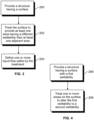
- Figure 3 illustrates a flow chart of a method of forming one or more liquid flow paths on a surface of a structure, according to an embodiment of the present disclosure.
- the structure 100 having the surface 104 is provided.
- the surface 104 is treated to provide at least one area having a different wettability than at least one area that is adjacent to the at least one area.
- the at least one area provides at least one liquid flow path 108, while the at least one area that is adjacent to the at least one area can be or include one or more banks 110.
- the one or more liquid flow paths 108 are defined by the treatment of the surface 104.
- the surface treatment of 202 can be performed through a variety of surface treatment processes.
- the structure 100 can be formed of a thermoplastic or thermoset, such as an epoxy or phenolic material.
- the treatment can be via an in-mold texturing, printing, bonding or cutting, chemical etching, painting using a blocking layer, and/or the like.
- the structure 100 can be nylon, PC, PPSU, PEI, or the like, and the treatment can be via superficial foaming, bonding, texturing, chemical etching, or the like.
- the treatment modifies at least a portion of the surface 104 to define one or more liquid flow paths 108 having a different wettability than a remainder of the main body 109, such as the banks 110.
- Treating a portion of the surface 104 of the structure 100 to form one or more liquid flow paths 108 can include texturing the portion to modify a wettability of the portion.
- treating the portion can include printing on the portion, such through three-dimensional printing, ink printing, laser printing, and/or the like, to modify a wettability of the portion.
- the treating can include chemically etching the portion to modify a wettability of the portion.
- the treating can include superficial foaming the portion to modify a wettability of the portion.
- the treating can include one or more of texturing the portion to modify a wettability of the portion, printing on the portion, chemically etching the portion to modify a wettability of the portion, and/or superficial foaming the portion to modify a wettability of the portion.
- the treatment of the surface 104 is via superficial foaming.
- a physical foaming agent such as high pressure carbon dioxide gas or supercritical carbon dioxide
- the physical foaming agent can be allowed to remain on the surface 104 for a predetermined period of time to diffuse into the area for a certain depth, such as ten minutes (optionally, the time period can be more or less than ten minutes, such as twenty minutes, or five minutes).
- the physical foaming agent is then removed, and the structure 100 can then be heated leading to superficial foaming, which thereby modifies the areas to a certain depth. In this manner, superficial foaming modifies a wettability of areas of the structure.
- an area to be treated may be sealed locally to maintain a high pressure gas state or supercritical state for the physical foaming agent.
- Figure 4 illustrates a flow chart of a method of forming one or more liquid flow paths on a surface of a structure, according to an embodiment of the present disclosure.
- the structure 100 having the surface 104 with 206 a first wettability is provided.
- the first wettability can be one in which water beads on the surface.
- the first wettability can be a relatively low wettability in that water beads thereon, instead of flowing over the surface 104.
- one or more areas are treated on the surface to alter the first wettability to a second wettability.
- the treatment can include superficial foaming, chemical etching, painting, printing, or the like.
- the one or more areas are desired locations for the liquid flow paths 108.
- the second wettability is greater than the first wettability. That is, the second wettability allows for increased liquid flow, and decreased liquid beading.
- the first wettability can be one in which water tends to flow over, as opposed to bead.
- the first wettability can be a relatively high wettability.
- areas on the surface 104 are treated to alter the first wettability to a second wettability that is less than the first wettability.
- the areas that are formed through surface treatment can be those that are desired to be the banks 110.
- the liquid flow paths 108 are formed between the banks 110.
- embodiments of the present disclosure provide a method of forming one or more liquid flow paths on a surface of a structure.
- the method includes providing the structure, and treating at least a portion of the surface of the structure to alter or otherwise modify a wettability thereof.
- the treating defines the liquid flow paths.
- a first wettability of the portion of the surface differs from a second wettability of a remainder of the surface.
- the first wettability allows for increased flow of liquid in comparison to the second wettability.
- the first wettability allows for decreased flow of liquid as compared to the second wettability.
- the treating increases the wettability, thereby providing the liquid flow paths at the locations of treatment (for example, at the portion(s) where treated). In at least one other embodiment, the treating decreases the wettability, thereby providing the liquid flow paths at locations other than the locations of the treatment (for example, at areas other than portion(s) where treated).
- a panel assembly according to the present disclosure may be used with various other vehicles, such as automobiles, buses, locomotives and train cars, watercraft, spacecraft, and the like.
- a panel assembly according to the present disclosure can be used to form structures having liquid flow paths for structures within buildings, articles of manufacture, or the like.
- Figure 6 illustrates a perspective view of a panel assembly 400 that forms a portion of wall 402 within an internal cabin of an aircraft, according to an embodiment of the present disclosure.
- the panel assembly 400 includes a plurality of window openings 404.
- the panel assembly 400 may not include window openings.
- the panel assembly 400 includes a first or inner ply 406, which faces the internal cabin.
- An outer surface 408 of the inner ply 406 facing away from the internal cabin may include a lining.
- the lining may be secured to the outer surface 408.
- the panel assembly 400 also includes a second or outer ply 410.
- insulation 412 is secured to an inner surface 414 of the outer ply 410 facing toward the internal cabin.
- the panel assembly 400 may not include the insulation 412.
- An outer surface 416 of the outer ply 410 is opposite from the inner surface 414.
- An air gap 418 may be formed between the inner ply 406 and the outer ply 410.
- the air gap 418 separates the inner ply 406 from the outer ply 410.
- the panel assembly 400 may not include the air gap. Instead, the inner ply 406 may be directly coupled to the outer ply 410.
- one or more surfaces of the panel assembly 400 include liquid flow paths, as described herein.
- the outer surface 408 of the inner ply 406 may include liquid flow paths, as described herein.
- the inner surface 414 of the outer ply 410 may include liquid flow paths.
- both the outer surface 408 of the inner ply 406 and the inner surface 414 of the outer ply 410 may include liquid flow paths.
- inner and outer surfaces of the inner ply 406 and inner and outer surfaces of the outer ply 410 may include liquid flow paths.
- a wall of an internal cabin of an aircraft may include one or more panel assemblies 400.
- various other portions of the aircraft may be formed by one or more panel assemblies 400.
- interior monuments such as lavatories, closets, cabinets, section dividers, and the like may include one or more panel assemblies 400.
- portions of stowage bin assemblies may include one or more panel assemblies 400.
- the panel assemblies 400 may be sized and shaped as desired.
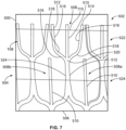
- Figure 7 illustrates a front view of a surface 500 of a panel assembly 502, according to an embodiment of the present disclosure.
- the panel assembly 400 shown in Figure 6 is an example of the panel assembly 502.
- the surface 500 has been treated to provide a liquid flow path 108, as described herein.
- the surface 500 may be an outer and/or inner surface of an outer ply (such as the outer ply 410 shown in Figure 6 ), an outer and/or inner surface of an inner ply (such as the inner ply 406 shown in Figure 6 ), and/or the like.
- the liquid flow path 108 includes a flow-directing network 504 that is configured to divert liquid to a desired location, such as toward a bottom 506 of the panel assembly 502, via gravity or inertial force.
- the flow-directing network 504 includes a plurality of interconnected flow director elements 508 formed between banks 110.
- the banks 110 provide barriers surrounding the flow-directing network 504.
- the flow-director elements 508 have a first wettability that is configured to allow for fluid flow, while the banks 110 have a second wettability that resists fluid flow.
- the first wettability is associated with a first surface energy.
- the second wettability is associated with a second surface energy, which is lower than the first surface energy (conversely, the first surface energy is higher than the second surface energy).
- the first surface energy provides a smooth surface that allows for fluid flow.
- the second surface energy provides a rough surface (that is, rougher than the smooth surface provided by the first surface energy) that resists fluid flow.
- liquid tends to bead on the banks 110.
- the liquid beads on the banks 110 moves to the liquid flow paths 108, via gravity, where the liquid then freely flows downwardly, via gravity, towards a desired location, such as towards the bottom 506.
- one or more of the flow director elements 508 includes a central stem 510 connected to a first lateral branch 512 and a second lateral branch 514.
- the central stem 510 provides a longitudinal channel that extends towards the bottom 506.
- the central stem 510 may be a linear channel, formed as described herein.
- the first lateral branch 512 may be a mirror image of the second lateral branch 514.
- the first lateral branch 512 and the second lateral branch 514 include an upper channel 516 that downwardly angles towards the central stem 510.
- the upper channels 516 connect to an inwardly-curved channel 518 (which inwardly curve towards the central stem 510).
- the inwardly-curved channel 518 connects to an outwardly-curved channel 518 that connects to a lower portion of the central stem 510, thereby providing a union 520 between the central stem 510, the first lateral branch 512, and the second lateral branch 514.
- the flow director elements 508 may be sized and shaped differently than shown. In at least one embodiment, the flow director elements 508 include more or less branches. For example, the flow director elements 508 may include two lateral branches on either side of the central stem 510. As another example, the flow director elements 508 may not include the central stem. As another example, the branches 512 and 514 may not be symmetrical about the central stem 510.
- the flow-directing network 504 includes a first row 522 of flow director elements 508 above a second row 524 of flow director elements 508.
- the second row 524 may be above a third row of flow director elements, and so on.
- the flow-directing network 504 may include only a single row of flow director elements 508.
- the panel assembly 502 may include a single flow director element 508.
- the union 520 of a flow director element 508 within the first row 522 connects to (for example, is in fluid communication with) a first lateral branch 512 of a first flow director element 508a of the second row 524 and a second lateral branch 514 of a second flow director element 508b of the second row 524.
- the first lateral branch 512 of the first flow director element 508a is integrally formed and connected with the second lateral branch 514 of the second flow director element 508b.
- flow director elements 508 within the first row 522 may interconnect and cascade with flow director elements 508 of the second row 524 (which may similarly interconnect and cascade with flow director elements 508 of a third row, and so on).
- the flow director elements 508 within the first row 522 may be sized and shaped the same as the flow director elements 508 within the second row 524.
- the flow director elements 508 within the first row 522 may be sized and shaped differently than the flow director elements 508 within the second row 524.
- the central stems 510 and/or the first and second lateral branches 512 and 514 of the flow director elements 508 within the second row 524 may be larger (for example, have increased height and/or area) than those within first row 522, or vice versa.
- the flow director elements 508 within each row may be sized and shaped the same or differently.
- the flow director elements 508 provide a pattern formed by surface treatment, as described herein, that is configured to divert liquid toward a desired location, such as the bottom 506 of the panel assembly 502.
- the sizes and shapes of the flow director elements 508 may vary depending on setting, application, part geometry, part orientation, and/or the like.
- moisture that condenses on the rougher areas, defined by the banks 110 forms beads.
- the external flow of liquid on the banks 110 flows in an uncontrolled manner until it intersects a portion of a flow director element 508, which provides a relatively smooth area that promotes controlled flow of liquid.
- the liquid flows in a controlled manner within the flow director element 508, via gravity, due to the relatively high surface energy of the flow director element 508.
- Adhesion of the liquid to the higher surface energy of the flow director element 508 prevents, minimizes, or otherwise reduces the potential of the liquid flowing onto the banks 110.
- the panel assembly 502 facilitates liquid flow by destabilizing droplet shapes on the roughened areas of the banks 110, allowing inertial forces to dominate surface tension, and promote flow into and through the liquid flow path 108, defined by the one or more flow director elements 508.
- Figure 8 illustrates a perspective front view of a panel assembly 600, according to an embodiment of the present disclosure.
- the panel assembly 400 shown in Figure 6 and the panel assembly 502 shown in Figure 5 are examples of and/or provide portions of the panel assembly 600 shown in Figure 8 , or vice versa.
- the panel assembly 600 includes a liquid flow path 108 formed on a surface 602 thereof.
- the liquid flow path 108 includes a flow-directing network 504 of interconnected and cascading flow director elements 508.
- the flow-directing network 504 includes ten or more rows of interconnected flow director elements 508.
- the flow-directing network 504 may include less than ten rows of interconnected flow director elements 508.
- Liquid on the surface 602 beads on the banks 110 and moves, via gravity or inertial force, into the flow director elements 508.
- the liquid flows downwardly in the direction of arrow A towards a lower drain channel 606 of the flow-directing network 504.
- the lower drain channel 606 is formed in the same manner as the liquid flow directors 508. That is, the lower drain channel 606 has a wettability that promotes liquid flow, in contrast to the banks 110.
- Lower drain channel 606 may include downwardly angled segments 608 that connect to the lowest row 610 of flow director elements 508.
- the segments 608 may, in turn, connect to drain outlets 612.
- the height or area of the flow director elements 508 within higher rows may be less than the height or area of the flow director elements 508 within lower rows. That is, a height of flow director elements in lower rows is greater than a height of flow director elements in upper rows.
- the height of flow director elements may progressively increase as rows descend. For example, the height 620 of the flow director elements 508 within the highest row 622 may be less than the height 624 of the flow director elements 508 within the lowest row 610.
- the increasing height progression from upper to lower rows accommodates and promotes increased flow rates.
- the flow-directing network 504 is circuitous and tortuous, with numerous interconnected and cascading flow director elements 508.
- the multiple potential paths for liquid flow defined by the numerous interconnected flow director elements 508 accommodate an increased volume of flow. That is, flow volume increases with the number of flow director elements 508.
- the interconnected flow director elements 508 define multiple directions for liquid flow, which ensures flow of liquid towards the bottom in the direction of arrow 604, even during orientational changes (such as when an aircraft changes altitude or attitude).
- the various directional changes defined by the numerous flow direction elements 508 within the flow-directing network 504 limit flow inertial velocity, which reduces a potential of a surge flow and/or liquid overflowing the banks 110.
- the panel assembly 600 may be formed of a composite thermoplastic or thermoset, for example.
- the pattern of flow director elements 508 within the flow-directing network 504 may be formed by surface treatment, as described herein.
- the flow director elements 508 may be formed by texture pattern on a forming die, chemical etching on a metallic surface, and/or the like.
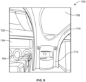
- FIG 9 illustrates a perspective internal view of an internal cabin 700 of a vehicle, (such as the aircraft 300 shown in Figure 5 ) according to an embodiment of the present disclosure.
- the internal cabin 700 includes numerous components that may be formed from and/or otherwise include panel assemblies, such as the panel assembly 400 (shown in Figure 6 ), the panel assembly 502 (shown in Figure 7 ), and the panel assembly 600 (shown in Figure 8 ).
- panel assemblies such as the panel assembly 400 (shown in Figure 6 ), the panel assembly 502 (shown in Figure 7 ), and the panel assembly 600 (shown in Figure 8 ).
- ceiling panels 702, stowage bin assemblies 704, sidewall panels 706, ceiling coves 708, doorway arch panels 710, doorway side panels 712, partitions, closets, lavatory walls, light valences, and/or the like may include panel assemblies, as described herein.
- FIG 10 illustrates a liquid flow system 800, according to an embodiment of the present disclosure.
- the liquid flow system 800 includes a first panel assembly 802 coupled to a second panel assembly 804, which, in turn, is coupled to a bilge 806, such as a bilge within an aircraft.
- the panel assemblies 802 and 804 are connected in series, with the first panel assembly 802 secured above the second panel assembly 804.
- the first panel assembly 802 includes a flow channel 808 (for example, a liquid flow path) that leads into a flow channel 810 (for example, a liquid flow path) of the second panel assembly 804.
- the flow channel 810 leads into the bilge 806.
- the flow channels 808 and 810 are formed through surface treatment, as described herein.
- the flow channels 808 and 810 may be sized and shaped differently than shown. Further, the liquid flow system 800 may include more or less panel assemblies than shown.
- the liquid flow system 800 such as a flow directing network, may include includes at least one flow transmission orifice 809 on the boundary of the outer surface of the first panel assembly 802.
- the area may be located and oriented such that liquid from the flow directing network is channeled to the orifice 809 and thus to adjacent aircraft components, such as to the second panel assembly 804.
- the adjacent components may also include flow direction features.
- the flow direction features of the adjacent component may couple to a flow directing network of the first component (for example, the first panel assembly 802).
- the flow directing network on the adjacent component may include a greater capacity such that liquid diverted by the at least one flow transmission orifice of the first component is accommodated along with moisture deposited on the outer surface of the second component from other sources.
- At least two adjacent components with surfaces that include flow directing networks are present such that liquid flows continuously across the outer surfaces of the at least two components.
- the surface of the at least two components may include a moisture control network that directs moisture towards a designated aircraft bilge zone, such as the bilge 806.
- embodiments of the present disclosure provide panel assemblies and methods of forming panel assemblies that are configured to efficiently manage moisture, such as within an aircraft, for example.
- the structures include liquid flow paths that are formed through surface treatment.
- Embodiments of the present disclosure provide lightweight and cost-effective structures that are integrally formed with liquid flow paths. As such, weight for a system can be reduced as there is a reduced need for separate and distinct moisture management devices. Instead, the structures that form portions of a system, such as an aircraft, are integrally formed with their own liquid flow paths that divert moisture to desired locations.
- Certain embodiments of the present disclosure provide a structure, such as a panel, sheet, or the like.
- the structure has a surface, such as an exposed outer surface.
- a portion of the surface is treated to modify a wettability of the portion of the structure.
- At least one liquid flow path is formed on the surface through the treated portion.
- a structure, limitation, or element that is "configured to” perform a task or operation is particularly structurally formed, constructed, or adapted in a manner corresponding to the task or operation.
- an object that is merely capable of being modified to perform the task or operation is not “configured to” perform the task or operation as used herein.
Landscapes
- Engineering & Computer Science (AREA)
- Mechanical Engineering (AREA)
- Aviation & Aerospace Engineering (AREA)
- General Engineering & Computer Science (AREA)
- Laminated Bodies (AREA)
- Physical Or Chemical Processes And Apparatus (AREA)
Claims (15)
- Ensemble panneau (400, 502, 600) pour une gestion d'humidité dans un aéronef, comprenant :au moins un trajet d'écoulement de liquide (108) formé sur au moins une surface (104, 500, 602) par traitement de surface (104, 500, 602),dans lequel l'au moins un trajet d'écoulement de liquide (108) est formé par rapport à au moins une berge (110) sur l'au moins une surface (104, 500, 602), etdans lequel l'au moins un trajet d'écoulement de liquide (108) est configuré pour dévier un liquide vers un emplacement souhaité, dans lequel l'au moins un trajet d'écoulement de liquide (108) a une première mouillabilité (112) associée à une première énergie de surface du liquide,caractérisé en ce que l'au moins une berge (110) a une seconde mouillabilité (114) qui est inférieure à la première mouillabilité (112) et qui est associée à une seconde énergie de surface du liquide inférieure à ladite première énergie de surface, dans lequel la première mouillabilité (112) permet un écoulement de liquide accru par comparaison à la seconde mouillabilité (114).
- Ensemble panneau (400, 502, 600) selon la revendication 1, dans lequel l'au moins un trajet d'écoulement de liquide (108) ayant la première mouillabilité (112) est non hydrophobe et favorise un écoulement d'humidité, et l'au moins une berge (110) ayant la seconde mouillabilité (114) est hydrophobe et freine un écoulement d'humidité.
- Ensemble panneau (400, 502, 600) selon la revendication 1, dans lequel ledit traitement de surface comporte une ou plusieurs opérations parmi une texturation d'une partie de ladite surface (104) pour modifier une mouillabilité de la partie, une impression sur la partie, une gravure chimique de la partie pour modifier une mouillabilité de la partie, et/ou un gonflement superficiel de la partie pour modifier une mouillabilité de la partie.
- Ensemble panneau (400, 502, 600) selon la revendication 1 ou 3, comprenant en outre :un premier pli ; etun second pli,dans lequel l'un, ou les deux, du premier pli ou du second pli comprend l'au moins une surface (104, 500, 602).
- Ensemble panneau (400, 502, 600) selon la revendication 4, dans lequel l'au moins une surface (104, 500, 602) comprend une surface extérieure (104, 500, 602) du premier pli, ou une surface intérieure (104, 500, 602) du second pli.
- Ensemble panneau (400, 502, 600) selon la revendication 4, comprenant en outre une isolation (412) fixée au second pli.
- Ensemble panneau (400, 502, 600) selon l'une quelconque des revendications 1 à 6, dans lequel l'au moins un trajet d'écoulement de liquide (108) (108) comprend un réseau de direction d'écoulement comportant une pluralité d'éléments directeurs d'écoulement interconnectés (508).
- Ensemble panneau (400, 502, 600) selon la revendication 7, dans lequel un ou plusieurs de la pluralité d'éléments directeurs d'écoulement interconnectés (508) comprend :une tige centrale (510) ;une première ramification latérale (512) reliée à la tige centrale (510) ; etune seconde ramification latérale (514) reliée à la tige centrale (510).
- Ensemble panneau (400, 502, 600) selon la revendication 8, dans lequel la première ramification latérale (512) est une image miroir de la seconde ramification latérale (514).
- Ensemble panneau (400, 502, 600) selon la revendication 8, dans lequel la première ramification latérale (512) et la seconde ramification latérale (514) comprennent :un canal supérieur (516) qui est incliné vers la tige centrale (510) ;un canal incurvé vers l'intérieur relié au canal supérieur (516) ; etun canal incurvé vers l'extérieur relié au canal incurvé vers l'intérieur et à une partie inférieure de la tige centrale (510).
- Ensemble panneau (400, 502, 600) selon la revendication 7, dans lequel le réseau de direction d'écoulement comprend :une première pluralité d'éléments directeurs d'écoulement (508) dans une première rangée (610, 622) ; etune seconde pluralité d'éléments directeurs d'écoulement (508) dans une seconde rangée (610, 622).
- Ensemble panneau (400, 502, 600) selon la revendication 11, dans lequel la pluralité d'éléments directeurs d'écoulement (508) dans la première rangée (610, 622) ont une première hauteur (620, 624), et dans lequel la pluralité d'éléments directeurs d'écoulement (508) dans la seconde rangée (610, 622) ont une seconde hauteur (620, 624) qui est supérieure à la première hauteur (620, 624).
- Ensemble panneau (400, 502, 600) selon la revendication 7, dans lequel le réseau de direction d'écoulement comprend au moins dix rangées des éléments directeurs d'écoulement (508), dans lequel une hauteur (620, 624) d'éléments directeurs d'écoulement (508) dans des rangées inférieures est supérieure à une hauteur (620, 624) d'éléments directeurs d'écoulement (508) dans des rangées supérieures.
- Aéronef (300) comprenant :une cabine interne (700) ; etau moins un composant à l'intérieur de la cabine interne (700), dans lequel l'au moins un composant comprend un ensemble panneau (400, 502, 600) selon l'une quelconque des revendications précédentes.
- Aéronef selon la revendication 14, dans lequel l'au moins un composant comprend un ou plusieurs parmi :un ou plusieurs panneaux de plafond (702) ;un ou plusieurs ensembles de compartiment à bagages (704) ;un ou plusieurs panneaux de paroi latérale (706) ;une ou plusieurs anses de plafond (708) ;un ou plusieurs panneaux d'arche d'embrasure de porte (710) ; ouun ou plusieurs panneaux latéraux d'embrasure de porte (712).
Applications Claiming Priority (1)
| Application Number | Priority Date | Filing Date | Title |
|---|---|---|---|
| US16/787,129 US12275520B2 (en) | 2020-02-11 | 2020-02-11 | Liquid-diverting panel assemblies |
Publications (2)
| Publication Number | Publication Date |
|---|---|
| EP3865397A1 EP3865397A1 (fr) | 2021-08-18 |
| EP3865397B1 true EP3865397B1 (fr) | 2025-04-09 |
Family
ID=74591756
Family Applications (1)
| Application Number | Title | Priority Date | Filing Date |
|---|---|---|---|
| EP21156387.9A Active EP3865397B1 (fr) | 2020-02-11 | 2021-02-10 | Procédés et assemblages de panneaux dérivantes de liquide |
Country Status (3)
| Country | Link |
|---|---|
| US (1) | US12275520B2 (fr) |
| EP (1) | EP3865397B1 (fr) |
| CN (1) | CN113247233A (fr) |
Families Citing this family (3)
| Publication number | Priority date | Publication date | Assignee | Title |
|---|---|---|---|---|
| US12275520B2 (en) | 2020-02-11 | 2025-04-15 | The Boeing Company | Liquid-diverting panel assemblies |
| US12269574B2 (en) * | 2020-02-11 | 2025-04-08 | The Boeing Company | Methods for forming liquid flow paths on a surface of a structure |
| EP4516518A1 (fr) * | 2023-08-30 | 2025-03-05 | The Boeing Company | Procédés de formation de motifs de gestion de liquide sur une surface d'une structure d'un véhicule |
Family Cites Families (43)
| Publication number | Priority date | Publication date | Assignee | Title |
|---|---|---|---|---|
| US3631923A (en) * | 1968-06-28 | 1972-01-04 | Hisaka Works Ltd | Plate-type condenser having condensed-liquid-collecting means |
| US3837396A (en) * | 1970-09-11 | 1974-09-24 | Borg Warner | Vertical surface vapor condensers |
| US5251849A (en) | 1989-12-26 | 1993-10-12 | Florida International University For Board Of Regents | Strain reduced airplane skin |
| US5827598A (en) | 1996-11-05 | 1998-10-27 | The Boeing Company | Method and apparatus for sealing an aircraft penetration |
| US5897079A (en) | 1997-08-18 | 1999-04-27 | Mcdonnell Douglas Corporation | Air curtain insulating system for aircraft cabin |
| US7051793B1 (en) * | 1998-04-20 | 2006-05-30 | Jurgen Schulz-Harder | Cooler for electrical components |
| US6945063B2 (en) * | 2002-06-28 | 2005-09-20 | Marine Desalination Systems, L.L.C. | Apparatus and method for harvesting atmospheric moisture |
| US20100210745A1 (en) * | 2002-09-09 | 2010-08-19 | Reactive Surfaces, Ltd. | Molecular Healing of Polymeric Materials, Coatings, Plastics, Elastomers, Composites, Laminates, Adhesives, and Sealants by Active Enzymes |
| US8828226B2 (en) * | 2003-03-01 | 2014-09-09 | The Trustees Of Boston University | System for assessing the efficacy of stored red blood cells using microvascular networks |
| US7282241B2 (en) | 2003-04-22 | 2007-10-16 | International Business Machines Corporation | Patterned, high surface area substrate with hydrophilic/hydrophobic contrast, and method of use |
| FR2865888B1 (fr) * | 2004-02-03 | 2008-08-29 | Thales Sa | Systeme de refroidissement d'un boitier electronique |
| US7083147B2 (en) | 2004-03-11 | 2006-08-01 | The Boeing Company | Modularized insulation, systems, apparatus, and methods |
| US20060068109A1 (en) | 2004-09-15 | 2006-03-30 | Airbus Deutschland Gmbh | Painting device, painting arrangement, method for painting a curved surface of an object, and use of an inkjet device for painting an aircraft |
| GB0618460D0 (en) | 2006-09-20 | 2006-11-01 | Univ Belfast | Process for preparing surfaces with tailored wettability |
| ES2444703T3 (es) | 2007-06-29 | 2014-02-26 | Cellutech Ab | Métodos para preparar superficies superhidrofóbicas sobre cuerpos sólidos mediante soluciones de expansión rápida |
| DE102008019070B3 (de) | 2008-04-15 | 2009-11-26 | Airbus Deutschland Gmbh | Verfahren zur Herstellung eines beidseitig mit Deckschichten versehenen Kernverbundes |
| US8292027B2 (en) | 2009-04-21 | 2012-10-23 | E I Du Pont De Nemours And Company | Composite laminate for a thermal and acoustic insulation blanket |
| EP2330019A1 (fr) | 2009-12-04 | 2011-06-08 | Sika Technology AG | Moulage inverse de déflecteur |
| KR101161726B1 (ko) * | 2009-12-28 | 2012-07-02 | 주식회사기린산업 | 장식판을 가진 단열패널 |
| US8317166B2 (en) | 2010-11-10 | 2012-11-27 | Koch-Glitsch, Lp | Liquid collection and distribution device for mass transfer column and process involving same |
| US20130168057A1 (en) * | 2011-12-30 | 2013-07-04 | Teledyne Scientific & Imaging, Llc | Modular heat shield and heat spreader |
| US9139739B2 (en) | 2012-07-13 | 2015-09-22 | The Board Of Trustees Of The University Of Illinois | Method for preparing micro-patterned superhydrophobic/superhydrophilic coatings |
| US20140349082A1 (en) | 2013-05-21 | 2014-11-27 | The Boeing Company | Folded Core Panel |
| JP6121854B2 (ja) * | 2013-09-18 | 2017-04-26 | 東芝ホームテクノ株式会社 | シート型ヒートパイプまたは携帯情報端末 |
| FR3012111B1 (fr) | 2013-10-17 | 2018-03-02 | Airbus Operations | Fuselage d'aeronef comprenant une isolation externe |
| US10421072B2 (en) | 2014-01-21 | 2019-09-24 | The Board Of Trustees Of The University Of Illinois | Wettability patterned substrates for pumpless liquid transport and drainage |
| JP6611734B2 (ja) | 2014-04-24 | 2019-11-27 | スリーエム イノベイティブ プロパティズ カンパニー | 親水性表面を有する流体制御フィルム、その作製方法、及び構造化表面を洗浄する方法 |
| US20160243586A1 (en) | 2014-08-01 | 2016-08-25 | The Boeing Company | Drag reduction riblets integrated in a paint layer |
| US11821409B2 (en) | 2015-01-06 | 2023-11-21 | The Boeing Company | Environmental aspect control assembly |
| WO2017031391A1 (fr) | 2015-08-19 | 2017-02-23 | The Regents Of The University Of California | Revêtements repoussant les liquides |
| US10023285B2 (en) * | 2015-10-16 | 2018-07-17 | The Boeing Company | Frame insulation providing enhanced drainage features |
| US10618624B2 (en) | 2015-10-27 | 2020-04-14 | The Boeing Company | Moisture accumulation prevention systems and methods |
| EP3394157B1 (fr) * | 2015-12-23 | 2019-09-25 | SABIC Global Technologies B.V. | Structure renforcée en mousse et procédé de formation associé, et article |
| EP3463832B1 (fr) | 2016-05-31 | 2022-04-20 | Nike Innovate C.V. | Procédé d'impression d'un objet profilé à l'aide de couches colorées et structurelles |
| US10907258B1 (en) | 2016-08-25 | 2021-02-02 | Arrowhead Center, Inc. | Surface modification of metals and alloys to alter wetting properties |
| RU2747809C2 (ru) * | 2016-11-18 | 2021-05-14 | Кимберли-Кларк Ворлдвайд, Инк. | Способ структурирования смачивания и модели для безнасосного переноса и точного управления объемами жидкостей на пористых материалах и через них |
| US10611478B2 (en) | 2017-04-24 | 2020-04-07 | Lockheed Martin Corporation | Structural panels for exposed surfaces |
| US10988230B2 (en) * | 2017-06-19 | 2021-04-27 | The Boeing Company | Passive moisture management bladder in an aircraft |
| KR102520278B1 (ko) | 2017-08-10 | 2023-04-11 | 가부시키가이샤 데라오카 세이사쿠쇼 | 접착 시트 |
| IT201800004727A1 (it) | 2018-04-19 | 2019-10-19 | Metodo per la realizzazione di materiali polimerici espansi stratificati | |
| US11142830B2 (en) | 2019-02-08 | 2021-10-12 | The Boeing Company | Method of surface micro-texturing with a subtractive agent |
| US20210138734A1 (en) | 2019-11-13 | 2021-05-13 | The Boeing Company | Foaming agent incorporated into a thermoplastic for an additive manufacturing system |
| US12275520B2 (en) | 2020-02-11 | 2025-04-15 | The Boeing Company | Liquid-diverting panel assemblies |
-
2020
- 2020-02-11 US US16/787,129 patent/US12275520B2/en active Active
-
2021
- 2021-02-10 EP EP21156387.9A patent/EP3865397B1/fr active Active
- 2021-02-18 CN CN202110187575.9A patent/CN113247233A/zh active Pending
Also Published As
| Publication number | Publication date |
|---|---|
| CN113247233A (zh) | 2021-08-13 |
| US20210245859A1 (en) | 2021-08-12 |
| US12275520B2 (en) | 2025-04-15 |
| EP3865397A1 (fr) | 2021-08-18 |
Similar Documents
| Publication | Publication Date | Title |
|---|---|---|
| EP3865397B1 (fr) | Procédés et assemblages de panneaux dérivantes de liquide | |
| AU637441B2 (en) | Strain reduced airplane skin | |
| RU2606332C2 (ru) | Самофиксируемые соединительные элементы для панельных конструкций и способы их изготовления | |
| EP3112257B1 (fr) | Panneau d'intérieur d'avion à matériaux acoustiques | |
| CA2883992C (fr) | Structure et methode de reduction de debit d'air dans un volume de paroi d'un aeronef | |
| AU2018214044B2 (en) | Composite sound absorption panel assembly | |
| EP2019774B1 (fr) | Revêtement interne insonorisant d'avions | |
| DE102009058227A1 (de) | Akustisch optimierte Klimaanlagenkomponenten | |
| US10173394B2 (en) | Methods and apparatus to vent gas and vapor from a panel via venting channels for a decorative layer | |
| US11433986B2 (en) | Movable barrier with pressure equalization features | |
| US11130560B2 (en) | Burnthrough resistant floor panels and method of manufacturing and installation | |
| EP3653491A1 (fr) | Structure de plancher d'aéronef | |
| WO2006114332A2 (fr) | Materiau d'isolation acoustique conçu pour l'isolation dans des avions | |
| US12269574B2 (en) | Methods for forming liquid flow paths on a surface of a structure | |
| DE102020002099B4 (de) | Vakuumisolationspaneel mit mindestens einer Stützschicht, Innenausstattungspaneel mit dem Vakuumisolationspaneel sowie Flugzeug mit dem Innenaustattungspaneel und/oder dem Vakuumisolationspaneel | |
| EP4516518A1 (fr) | Procédés de formation de motifs de gestion de liquide sur une surface d'une structure d'un véhicule | |
| US20230398568A1 (en) | Methods for forming liquid management patterns on a surface of a structure of a vehicle | |
| US11260619B2 (en) | Composite panel systems and methods | |
| EP0936377A2 (fr) | Structure sacrificielle absorbant de l'énergie | |
| US11052987B2 (en) | Integrally damped composite aircraft floor panels | |
| US20150274303A1 (en) | Structure and Method for Reducing Air Flow in a Wall Volume of an Aircraft | |
| EP4238867B1 (fr) | Ensemble panneau de véhicule et procédé d'assemblage de panneau | |
| EP4631716A1 (fr) | Systèmes et procédés de formation d'une structure comprenant un produit de résine d'origine biologique | |
| DE102024121862A1 (de) | Nutzfahrzeugkabine für ein Nutzfahrzeug und Nutzfahrzeug mit einer solchen Nutzfahrzeugkabine |
Legal Events
| Date | Code | Title | Description |
|---|---|---|---|
| PUAI | Public reference made under article 153(3) epc to a published international application that has entered the european phase |
Free format text: ORIGINAL CODE: 0009012 |
|
| STAA | Information on the status of an ep patent application or granted ep patent |
Free format text: STATUS: THE APPLICATION HAS BEEN PUBLISHED |
|
| AK | Designated contracting states |
Kind code of ref document: A1 Designated state(s): AL AT BE BG CH CY CZ DE DK EE ES FI FR GB GR HR HU IE IS IT LI LT LU LV MC MK MT NL NO PL PT RO RS SE SI SK SM TR |
|
| STAA | Information on the status of an ep patent application or granted ep patent |
Free format text: STATUS: REQUEST FOR EXAMINATION WAS MADE |
|
| 17P | Request for examination filed |
Effective date: 20220216 |
|
| RBV | Designated contracting states (corrected) |
Designated state(s): AL AT BE BG CH CY CZ DE DK EE ES FI FR GB GR HR HU IE IS IT LI LT LU LV MC MK MT NL NO PL PT RO RS SE SI SK SM TR |
|
| STAA | Information on the status of an ep patent application or granted ep patent |
Free format text: STATUS: EXAMINATION IS IN PROGRESS |
|
| 17Q | First examination report despatched |
Effective date: 20230217 |
|
| RAP3 | Party data changed (applicant data changed or rights of an application transferred) |
Owner name: THE BOEING COMPANY |
|
| GRAP | Despatch of communication of intention to grant a patent |
Free format text: ORIGINAL CODE: EPIDOSNIGR1 |
|
| STAA | Information on the status of an ep patent application or granted ep patent |
Free format text: STATUS: GRANT OF PATENT IS INTENDED |
|
| RIC1 | Information provided on ipc code assigned before grant |
Ipc: B32B 3/30 20060101ALI20240627BHEP Ipc: B64C 1/06 20060101ALI20240627BHEP Ipc: B64C 1/12 20060101AFI20240627BHEP |
|
| INTG | Intention to grant announced |
Effective date: 20240718 |
|
| GRAJ | Information related to disapproval of communication of intention to grant by the applicant or resumption of examination proceedings by the epo deleted |
Free format text: ORIGINAL CODE: EPIDOSDIGR1 |
|
| STAA | Information on the status of an ep patent application or granted ep patent |
Free format text: STATUS: EXAMINATION IS IN PROGRESS |
|
| GRAP | Despatch of communication of intention to grant a patent |
Free format text: ORIGINAL CODE: EPIDOSNIGR1 |
|
| STAA | Information on the status of an ep patent application or granted ep patent |
Free format text: STATUS: GRANT OF PATENT IS INTENDED |
|
| INTC | Intention to grant announced (deleted) | ||
| INTG | Intention to grant announced |
Effective date: 20241010 |
|
| GRAS | Grant fee paid |
Free format text: ORIGINAL CODE: EPIDOSNIGR3 |
|
| GRAA | (expected) grant |
Free format text: ORIGINAL CODE: 0009210 |
|
| STAA | Information on the status of an ep patent application or granted ep patent |
Free format text: STATUS: THE PATENT HAS BEEN GRANTED |
|
| P01 | Opt-out of the competence of the unified patent court (upc) registered |
Free format text: CASE NUMBER: APP_5404/2025 Effective date: 20250131 |
|
| AK | Designated contracting states |
Kind code of ref document: B1 Designated state(s): AL AT BE BG CH CY CZ DE DK EE ES FI FR GB GR HR HU IE IS IT LI LT LU LV MC MK MT NL NO PL PT RO RS SE SI SK SM TR |
|
| REG | Reference to a national code |
Ref country code: GB Ref legal event code: FG4D |
|
| REG | Reference to a national code |
Ref country code: CH Ref legal event code: EP |
|
| REG | Reference to a national code |
Ref country code: DE Ref legal event code: R096 Ref document number: 602021028740 Country of ref document: DE |
|
| REG | Reference to a national code |
Ref country code: IE Ref legal event code: FG4D |
|
| REG | Reference to a national code |
Ref country code: NL Ref legal event code: MP Effective date: 20250409 |
|
| PG25 | Lapsed in a contracting state [announced via postgrant information from national office to epo] |
Ref country code: NL Free format text: LAPSE BECAUSE OF FAILURE TO SUBMIT A TRANSLATION OF THE DESCRIPTION OR TO PAY THE FEE WITHIN THE PRESCRIBED TIME-LIMIT Effective date: 20250409 |
|
| REG | Reference to a national code |
Ref country code: AT Ref legal event code: MK05 Ref document number: 1783335 Country of ref document: AT Kind code of ref document: T Effective date: 20250409 |
|
| PG25 | Lapsed in a contracting state [announced via postgrant information from national office to epo] |
Ref country code: ES Free format text: LAPSE BECAUSE OF FAILURE TO SUBMIT A TRANSLATION OF THE DESCRIPTION OR TO PAY THE FEE WITHIN THE PRESCRIBED TIME-LIMIT Effective date: 20250409 Ref country code: PT Free format text: LAPSE BECAUSE OF FAILURE TO SUBMIT A TRANSLATION OF THE DESCRIPTION OR TO PAY THE FEE WITHIN THE PRESCRIBED TIME-LIMIT Effective date: 20250811 Ref country code: FI Free format text: LAPSE BECAUSE OF FAILURE TO SUBMIT A TRANSLATION OF THE DESCRIPTION OR TO PAY THE FEE WITHIN THE PRESCRIBED TIME-LIMIT Effective date: 20250409 |
|
| REG | Reference to a national code |
Ref country code: LT Ref legal event code: MG9D |
|
| PG25 | Lapsed in a contracting state [announced via postgrant information from national office to epo] |
Ref country code: GR Free format text: LAPSE BECAUSE OF FAILURE TO SUBMIT A TRANSLATION OF THE DESCRIPTION OR TO PAY THE FEE WITHIN THE PRESCRIBED TIME-LIMIT Effective date: 20250710 Ref country code: NO Free format text: LAPSE BECAUSE OF FAILURE TO SUBMIT A TRANSLATION OF THE DESCRIPTION OR TO PAY THE FEE WITHIN THE PRESCRIBED TIME-LIMIT Effective date: 20250709 |
|
| PG25 | Lapsed in a contracting state [announced via postgrant information from national office to epo] |
Ref country code: PL Free format text: LAPSE BECAUSE OF FAILURE TO SUBMIT A TRANSLATION OF THE DESCRIPTION OR TO PAY THE FEE WITHIN THE PRESCRIBED TIME-LIMIT Effective date: 20250409 |
|
| PG25 | Lapsed in a contracting state [announced via postgrant information from national office to epo] |
Ref country code: BG Free format text: LAPSE BECAUSE OF FAILURE TO SUBMIT A TRANSLATION OF THE DESCRIPTION OR TO PAY THE FEE WITHIN THE PRESCRIBED TIME-LIMIT Effective date: 20250409 |
|
| PG25 | Lapsed in a contracting state [announced via postgrant information from national office to epo] |
Ref country code: HR Free format text: LAPSE BECAUSE OF FAILURE TO SUBMIT A TRANSLATION OF THE DESCRIPTION OR TO PAY THE FEE WITHIN THE PRESCRIBED TIME-LIMIT Effective date: 20250409 |
|
| PG25 | Lapsed in a contracting state [announced via postgrant information from national office to epo] |
Ref country code: AT Free format text: LAPSE BECAUSE OF FAILURE TO SUBMIT A TRANSLATION OF THE DESCRIPTION OR TO PAY THE FEE WITHIN THE PRESCRIBED TIME-LIMIT Effective date: 20250409 |
|
| PG25 | Lapsed in a contracting state [announced via postgrant information from national office to epo] |
Ref country code: RS Free format text: LAPSE BECAUSE OF FAILURE TO SUBMIT A TRANSLATION OF THE DESCRIPTION OR TO PAY THE FEE WITHIN THE PRESCRIBED TIME-LIMIT Effective date: 20250709 |
|
| PG25 | Lapsed in a contracting state [announced via postgrant information from national office to epo] |
Ref country code: IS Free format text: LAPSE BECAUSE OF FAILURE TO SUBMIT A TRANSLATION OF THE DESCRIPTION OR TO PAY THE FEE WITHIN THE PRESCRIBED TIME-LIMIT Effective date: 20250809 |
|
| PG25 | Lapsed in a contracting state [announced via postgrant information from national office to epo] |
Ref country code: LV Free format text: LAPSE BECAUSE OF FAILURE TO SUBMIT A TRANSLATION OF THE DESCRIPTION OR TO PAY THE FEE WITHIN THE PRESCRIBED TIME-LIMIT Effective date: 20250409 |
|
| PG25 | Lapsed in a contracting state [announced via postgrant information from national office to epo] |
Ref country code: DK Free format text: LAPSE BECAUSE OF FAILURE TO SUBMIT A TRANSLATION OF THE DESCRIPTION OR TO PAY THE FEE WITHIN THE PRESCRIBED TIME-LIMIT Effective date: 20250409 Ref country code: SM Free format text: LAPSE BECAUSE OF FAILURE TO SUBMIT A TRANSLATION OF THE DESCRIPTION OR TO PAY THE FEE WITHIN THE PRESCRIBED TIME-LIMIT Effective date: 20250409 |
|
| PG25 | Lapsed in a contracting state [announced via postgrant information from national office to epo] |
Ref country code: CZ Free format text: LAPSE BECAUSE OF FAILURE TO SUBMIT A TRANSLATION OF THE DESCRIPTION OR TO PAY THE FEE WITHIN THE PRESCRIBED TIME-LIMIT Effective date: 20250409 |
|
| PG25 | Lapsed in a contracting state [announced via postgrant information from national office to epo] |
Ref country code: EE Free format text: LAPSE BECAUSE OF FAILURE TO SUBMIT A TRANSLATION OF THE DESCRIPTION OR TO PAY THE FEE WITHIN THE PRESCRIBED TIME-LIMIT Effective date: 20250409 |
|
| PG25 | Lapsed in a contracting state [announced via postgrant information from national office to epo] |
Ref country code: RO Free format text: LAPSE BECAUSE OF FAILURE TO SUBMIT A TRANSLATION OF THE DESCRIPTION OR TO PAY THE FEE WITHIN THE PRESCRIBED TIME-LIMIT Effective date: 20250409 Ref country code: SK Free format text: LAPSE BECAUSE OF FAILURE TO SUBMIT A TRANSLATION OF THE DESCRIPTION OR TO PAY THE FEE WITHIN THE PRESCRIBED TIME-LIMIT Effective date: 20250409 |
|
| PG25 | Lapsed in a contracting state [announced via postgrant information from national office to epo] |
Ref country code: IT Free format text: LAPSE BECAUSE OF FAILURE TO SUBMIT A TRANSLATION OF THE DESCRIPTION OR TO PAY THE FEE WITHIN THE PRESCRIBED TIME-LIMIT Effective date: 20250409 |