EP3865394A1 - Hybrid system for ship and control method for hybrid system for ship - Google Patents
Hybrid system for ship and control method for hybrid system for ship Download PDFInfo
- Publication number
- EP3865394A1 EP3865394A1 EP19870475.1A EP19870475A EP3865394A1 EP 3865394 A1 EP3865394 A1 EP 3865394A1 EP 19870475 A EP19870475 A EP 19870475A EP 3865394 A1 EP3865394 A1 EP 3865394A1
- Authority
- EP
- European Patent Office
- Prior art keywords
- engine
- electric motor
- power
- path
- hybrid system
- Prior art date
- Legal status (The legal status is an assumption and is not a legal conclusion. Google has not performed a legal analysis and makes no representation as to the accuracy of the status listed.)
- Pending
Links
- 238000000034 method Methods 0.000 title claims description 18
- 238000010248 power generation Methods 0.000 claims description 38
- 239000000446 fuel Substances 0.000 claims description 24
- 230000005540 biological transmission Effects 0.000 claims description 22
- 238000002485 combustion reaction Methods 0.000 claims description 4
- 238000010586 diagram Methods 0.000 description 6
- 230000006866 deterioration Effects 0.000 description 5
- 230000007547 defect Effects 0.000 description 4
- 230000001172 regenerating effect Effects 0.000 description 3
- 239000000470 constituent Substances 0.000 description 2
- 239000002803 fossil fuel Substances 0.000 description 2
- 230000002093 peripheral effect Effects 0.000 description 2
- XLYOFNOQVPJJNP-UHFFFAOYSA-N water Substances O XLYOFNOQVPJJNP-UHFFFAOYSA-N 0.000 description 2
- 238000006243 chemical reaction Methods 0.000 description 1
- 238000004891 communication Methods 0.000 description 1
- 238000012937 correction Methods 0.000 description 1
- 238000001514 detection method Methods 0.000 description 1
- 238000011161 development Methods 0.000 description 1
- 230000000694 effects Effects 0.000 description 1
- 230000007613 environmental effect Effects 0.000 description 1
- 239000000463 material Substances 0.000 description 1
- 238000012544 monitoring process Methods 0.000 description 1
- 230000007704 transition Effects 0.000 description 1
Images


Classifications
-
- B—PERFORMING OPERATIONS; TRANSPORTING
- B63—SHIPS OR OTHER WATERBORNE VESSELS; RELATED EQUIPMENT
- B63H—MARINE PROPULSION OR STEERING
- B63H23/00—Transmitting power from propulsion power plant to propulsive elements
- B63H23/02—Transmitting power from propulsion power plant to propulsive elements with mechanical gearing
- B63H23/10—Transmitting power from propulsion power plant to propulsive elements with mechanical gearing for transmitting drive from more than one propulsion power unit
- B63H23/12—Transmitting power from propulsion power plant to propulsive elements with mechanical gearing for transmitting drive from more than one propulsion power unit allowing combined use of the propulsion power units
-
- B—PERFORMING OPERATIONS; TRANSPORTING
- B63—SHIPS OR OTHER WATERBORNE VESSELS; RELATED EQUIPMENT
- B63H—MARINE PROPULSION OR STEERING
- B63H21/00—Use of propulsion power plant or units on vessels
- B63H21/20—Use of propulsion power plant or units on vessels the vessels being powered by combinations of different types of propulsion units
-
- B—PERFORMING OPERATIONS; TRANSPORTING
- B63—SHIPS OR OTHER WATERBORNE VESSELS; RELATED EQUIPMENT
- B63H—MARINE PROPULSION OR STEERING
- B63H21/00—Use of propulsion power plant or units on vessels
- B63H21/12—Use of propulsion power plant or units on vessels the vessels being motor-driven
- B63H21/14—Use of propulsion power plant or units on vessels the vessels being motor-driven relating to internal-combustion engines
-
- B—PERFORMING OPERATIONS; TRANSPORTING
- B63—SHIPS OR OTHER WATERBORNE VESSELS; RELATED EQUIPMENT
- B63H—MARINE PROPULSION OR STEERING
- B63H21/00—Use of propulsion power plant or units on vessels
- B63H21/12—Use of propulsion power plant or units on vessels the vessels being motor-driven
- B63H21/17—Use of propulsion power plant or units on vessels the vessels being motor-driven by electric motor
-
- B—PERFORMING OPERATIONS; TRANSPORTING
- B63—SHIPS OR OTHER WATERBORNE VESSELS; RELATED EQUIPMENT
- B63H—MARINE PROPULSION OR STEERING
- B63H21/00—Use of propulsion power plant or units on vessels
- B63H21/21—Control means for engine or transmission, specially adapted for use on marine vessels
-
- B—PERFORMING OPERATIONS; TRANSPORTING
- B63—SHIPS OR OTHER WATERBORNE VESSELS; RELATED EQUIPMENT
- B63H—MARINE PROPULSION OR STEERING
- B63H23/00—Transmitting power from propulsion power plant to propulsive elements
- B63H23/30—Transmitting power from propulsion power plant to propulsive elements characterised by use of clutches
-
- B—PERFORMING OPERATIONS; TRANSPORTING
- B63—SHIPS OR OTHER WATERBORNE VESSELS; RELATED EQUIPMENT
- B63H—MARINE PROPULSION OR STEERING
- B63H21/00—Use of propulsion power plant or units on vessels
- B63H21/20—Use of propulsion power plant or units on vessels the vessels being powered by combinations of different types of propulsion units
- B63H2021/202—Use of propulsion power plant or units on vessels the vessels being powered by combinations of different types of propulsion units of hybrid electric type
-
- B—PERFORMING OPERATIONS; TRANSPORTING
- B63—SHIPS OR OTHER WATERBORNE VESSELS; RELATED EQUIPMENT
- B63H—MARINE PROPULSION OR STEERING
- B63H21/00—Use of propulsion power plant or units on vessels
- B63H21/20—Use of propulsion power plant or units on vessels the vessels being powered by combinations of different types of propulsion units
- B63H2021/202—Use of propulsion power plant or units on vessels the vessels being powered by combinations of different types of propulsion units of hybrid electric type
- B63H2021/205—Use of propulsion power plant or units on vessels the vessels being powered by combinations of different types of propulsion units of hybrid electric type the second power unit being of the internal combustion engine type, or the like, e.g. a Diesel engine
-
- B—PERFORMING OPERATIONS; TRANSPORTING
- B63—SHIPS OR OTHER WATERBORNE VESSELS; RELATED EQUIPMENT
- B63H—MARINE PROPULSION OR STEERING
- B63H23/00—Transmitting power from propulsion power plant to propulsive elements
- B63H23/02—Transmitting power from propulsion power plant to propulsive elements with mechanical gearing
- B63H2023/0258—Transmitting power from propulsion power plant to propulsive elements with mechanical gearing comprising gearings with variable gear ratio, other than reversing drives or trolling drives
- B63H2023/0266—Transmitting power from propulsion power plant to propulsive elements with mechanical gearing comprising gearings with variable gear ratio, other than reversing drives or trolling drives comprising gearings with automatically variable gear ratio, other than continuously variable transmissions or trolling drives
-
- Y—GENERAL TAGGING OF NEW TECHNOLOGICAL DEVELOPMENTS; GENERAL TAGGING OF CROSS-SECTIONAL TECHNOLOGIES SPANNING OVER SEVERAL SECTIONS OF THE IPC; TECHNICAL SUBJECTS COVERED BY FORMER USPC CROSS-REFERENCE ART COLLECTIONS [XRACs] AND DIGESTS
- Y02—TECHNOLOGIES OR APPLICATIONS FOR MITIGATION OR ADAPTATION AGAINST CLIMATE CHANGE
- Y02T—CLIMATE CHANGE MITIGATION TECHNOLOGIES RELATED TO TRANSPORTATION
- Y02T70/00—Maritime or waterways transport
- Y02T70/50—Measures to reduce greenhouse gas emissions related to the propulsion system
- Y02T70/5218—Less carbon-intensive fuels, e.g. natural gas, biofuels
- Y02T70/5236—Renewable or hybrid-electric solutions
Definitions
- the present disclosure relates to a marine hybrid system that can be equipped with a hybrid propulsion ship including an engine and an electric motor as power sources, and a control method for the marine hybrid system.
- a thrust for sailing is obtained by driving a thrust generation device such as a propeller by a power source.
- a thrust generation device such as a propeller
- an engine which is an internal combustion engine consuming a fossil fuel has mainly been used as the power source.
- development of a so-called hybrid propulsion ship is advanced which includes, in addition to the conventional engine, an electric motor (electric motor drive) that can be driven by using electric energy stored in a battery or the like.
- Patent Document 1 discloses an example of the hybrid propulsion ship.
- Patent Document 1 JP2013-147186A
- a mechanical engine prevails which can adjust an output obtained by control of a rotations peed, by manually performing a throttle operation by an operator.
- the mechanical engine is operated by, for example, grasping a rotation speed-output characteristics of the engine in advance, and controlling the rotation speed by the throttle operation in consideration of a wind direction and a tide.
- a mechanical engine is often used as the engine, like the conventional ship.
- the operator is required of not only the throttle operation of the engine but also selection of the operation mode as in Patent Document 1 above.
- a sailing power generation mode in which power is generated by the electric motor with a part of power of the engine while obtaining a thrust by driving the engine
- a stop power generation mode in which power is generated by driving the electric motor with the power of the engine while the ship is stopped are considered.
- electric energy can be supplied by regeneratively driving the electric motor, which is effective in improving energy efficiency of the ship.
- the sailing power generation mode if a power generation load of the electric motor increases, the engine may be brought into an overload condition depending on a sailing condition. Bringing the engine into the overload condition, various defects such as excessive wear, oil deterioration, and seizure are carried, and a failure may be caused if the defects further advance.
- At least one embodiment of the present invention is made in view of the above, and an object of the present invention is to provide a marine hybrid system capable of appropriately performing drive control of the engine and the electric motor in accordance with the sailing condition while preventing the engine from being brought into the overload condition, and a control method for the marine hybrid system.
- a marine hybrid system includes an engine, an electric motor, a thrust generation device capable of generating a thrust of a ship by using an output of at least one of the engine or the electric motor, a clutch mechanism configured to be able to switch connection states between the engine, the electric motor, and the thrust generation device, an overload determination part for determining whether the engine is in an overload condition, and a control device for controlling a connection state of the clutch mechanism.
- the control device controls the clutch mechanism such that a load of the engine is reduced, if the overload determination part determines that the engine is in the overload condition.
- the overload determination part determines whether the engine is in the overload condition in a sailing power generation mode where power is generated by the electric motor during sailing by supplying the output of the engine to the thrust generation device and the electric motor.
- the clutch mechanism includes a first clutch disposed between the thrust generation device and an intermediate shaft, second clutches disposed between the intermediate shaft and the engine, and a third clutch disposed between the intermediate shaft and the drive motor, the second clutches are disposed in parallel, and include a power transmission path including a first path and a second path different from each other in transmission ratio, and the control device is configured to be able to adjust the load of the engine by alternatively switching the first path or the second path, if the second clutches are connected.
- the power transmission path connected to the engine includes the first path and the second path.
- the first path and the second path are configured to be different from each other in transmission ratio, and are switched if the overload condition is determined, making it possible to reduce the load of the engine.
- the second path is set to have the transmission ratio lower than that of the first path, and the control device controls the clutch mechanism such that the power transmission path of the second clutches is switched from the first path to the second path, if the overload determination part determines that the internal combustion engine is in the overload condition.
- the power transmission path is switched from the first path having the higher transmission ratio to the second path having the lower transmission ratio, making it possible to reduce the load of the engine.
- the ship has a plurality of operation modes
- the plurality of operation modes include an engine drive mode in which the ship sails by power of the engine, a motor drive mode in which the ship sails by power of the electric motor, a motor assist mode in which the ship sails by power of both of the engine and the electric motor, a sailing power generation mode in which power is generated by the electric motor while the ship sails by the power of the engine, and a stop power generation mode in which power is generated by the electric motor while the thrust power generation device is stopped, and the control device controls the clutch mechanism such that the load of the engine is reduced, if the overload determination part determines that the engine is in the overload condition, in the sailing power generation mode of the operation modes.
- the ship has the engine drive mode, the motor drive mode, the motor assist mode, the sailing power generation mode, and the stop power generation mode. Then, if the engine is brought into the overload condition by an increase in load needed for regenerative drive of the electric motor in the sailing power generation mode of these five operation modes, controlling the clutch mechanism such that the load of the engine is reduced as described above, it is possible to adequately prevent the engine from being brought into the overload condition.
- the marine hybrid system further includes a storage device for storing an output characteristic curve defining a relationship between a rotation speed and an output of the thrust generation device in each of the plurality of operation modes, and fuel-efficiency map data of the engine, a target output calculation part for calculating a target output of the thrust generation device, and an operation mode selection part for calculating, based on the output characteristic curve and fuel map data, a fuel consumption rate in each of the operation modes corresponding to the target output, and selecting, based on the fuel consumption rate in each of the operation modes, the operation mode to be implemented.
- a fuel consumption rate in each operation mode relative to the target output of the ship is calculated. Then, comparing the fuel consumption rates assumed in the respective operation modes, it is possible to implement efficient sailing while selecting the optimum operation mode. In particular, if the fuel consumption rate is given priority, performing the above-described control, it is possible to switch the operation modes so that the optimum fuel consumption rate is obtained.
- the engine is a mechanical engine capable of controlling a rotation speed by a throttle operation of an operator.
- a control method for a marine hybrid system which includes an engine, an electric motor, a thrust generation device capable of generating a thrust of a ship by using an output of at least one of the engine or the electric motor, and a clutch mechanism configured to be able to switch connection states between the engine, the electric motor, and the thrust generation device, according to at least one embodiment of the present invention, includes an overload determination step of determining whether the engine is in an overload condition, and a control step of controlling the clutch mechanism such that a load of the engine is reduced, if it is determined that the engine is in the overload condition.
- control step includes determining whether the engine is in the overload condition in a sailing power generation mode where power is generated by the electric motor during sailing by supplying the output of the engine to the thrust generation device and the electric motor.
- a marine hybrid system capable of appropriately performing drive control of an engine and an electric motor in accordance with a sailing condition while preventing the engine from being brought into an overload condition, and a control method for the marine hybrid system.
- FIG. 1 is an overall configuration diagram of a marine hybrid system 1 according to at least one embodiment of the present invention.
- the marine hybrid system 1 includes an engine 2 and an electric motor 4 as power sources of a ship sailing on water.
- the engine 2 is an internal combustion engine capable of outputting power by consuming a fossil fuel.
- the electric motor 4 is an electric motor drive capable of outputting power by being driven (power-driven) by power (electric energy) stored in a battery 6 mounted on the ship.
- the electric motor 4 can function as a generator by being mechanically driven (regeneratively driven) from outside. In this case, power generated by the electric motor 4 is stored in the battery 6.
- various power conversion elements such as an inverter and a converter may be disposed on an electric path between the electric motor 4 and the battery 6.
- a thrust generation device 8 is a device for generating a thrust for sailing of the ship by being driven by power output from at least one of the engine 2 or the electric motor 4.
- the thrust generation device 8 is, for example, a propeller.
- the thrust generation device 8 is connected to the engine 2 and the electric motor 4 via a clutch mechanism 10.
- a connection state of the clutch mechanism 10 at least one of the engine 2 or the electric motor 4 is connected to the thrust generation device 8 in terms of power.
- the ship obtains the thrust by driving the thrust generation device 8 by using the output of at least one of the engine 2 or the electric motor 4.
- the clutch mechanism 10 is configured to be able to switch connection states between the engine 2, the electric motor 4, and the thrust generation device 8.
- the clutch mechanism 10 includes a first clutch 14 configured to be able to disconnect an intermediate shaft 12 and an input shaft 8a of the thrust generation device 8, second clutches 16 configured to be able to disconnect the intermediate shaft 12 and the engine 2, and a third clutch 18 configured to be able to disconnect the intermediate shaft 12 and the electric motor 4.
- the above-described first clutch 14, second clutches 16 and third clutch 18 are configured to be able to connect/disconnect the engine 2, the electric motor 4, and the thrust generation device 8 in terms of power, by switching respective connection states.
- FIG. 2 is a detailed diagram of the second clutches 16 in FIG. 1 .
- the second clutches 16 disposed between the engine 2 and the intermediate shaft 12 include a first path 16a and a second path 16b disposed in parallel.
- the first path 16a and the second path 16b include a first subclutch 17a and a second subclutch 17b, respectively, and are configured to be independently connectable.
- the first path 16a and the second path 16b include a transmission mechanism 19 on a side of the engine 2.
- the transmission mechanism 19 includes a first gear 20a disposed at an end of the first path 16a, a second gear 20b disposed at an end of the second path 16b, and a third gear 20c disposed on the side of an output shaft of the engine 2.
- the first gear 20a, the second gear 20b, and the third gear 20c are set to each have a predetermined transmission ratio when power is transmitted in the first path 16a and the second path 16b.
- the first gear 20a, the second gear 20b, and the third gear 20c are set to have different transmission ratios in the first path 16a and the second path 16b.
- the second path 16b is set to have a lower transmission ratio than that of the first path 16a (in other words, the first path 16a has a low gear, and the second path 16b has a high gear).
- control is performed such that the first path 16a is selected first as default (the first subclutch 17a enters a connected state, and the second subclutch 17b enters a disconnected state), and if a predetermined condition is satisfied (step S7 in FIG. 5 to be described later: YES), the second path 16b is selected (the first subclutch 17a enters the disconnected state, and the second subclutch 17b enters the connected state).
- the marine hybrid system 1 includes the control device 25.
- the control device 25 is configured as a control unit for the marine hybrid system 1 by including hardware constituted by an electronic computation device such as a computer and installing, on the hardware, a program for performing the control method for the marine hybrid system 1 according to at least one embodiment of the present invention.
- the program can be installed by reading, for example, a program stored in a predetermined storage medium with a reading device of the hardware, and the program and the storage medium storing the program also fall within the technical scope of the present invention.
- the control device 25 controls the marine hybrid system 1 by transmitting/receiving various control signals to the respective constituent elements of the marine hybrid system 1.
- flows of the control signals are representatively indicated by dashed lines, respectively, in a range necessary for the following description.
- the control device 25 causes the engine 2, the electric motor 4, and the clutch mechanism 10 to cooperate each other, thereby configuring such that five operation modes can be performed.
- the five operation modes include an engine drive mode, a motor drive mode, a motor assist mode, a sailing power generation mode, and a stop power generation mode.
- FIG. 3 is a list showing connection states of the first clutch 14, the second clutches 16, and the third clutch 18, and drive states of the engine 2 and the electric motor 4 in the respective operation modes.
- the engine drive mode is the operation mode in which the thrust for sailing is generated by driving the thrust generation device 8 only by the engine 2.
- the first clutch 14 and the second clutches 16 are set in the connected state, and the third clutch is set in the disconnected state.
- the engine 2 and the thrust generation device 8 are connected in terms of power
- the electric motor 4 is disconnected in terms of power from the engine 2 and the thrust generation device 8.
- power output from the engine 2 serving as the power source is transmitted to the thrust generation device 8 via the clutch mechanism 10, obtaining a thrust force of the ship.
- the electric motor 4 is in a stopped state (disconnected in terms of power, the electric motor 4 may be driven; however, the electric motor 4 is preferably in the stopped state in order to avoid wasteful electric power consumption).
- the motor drive mode is the operation mode in which the thrust for sailing is generated by driving the thrust generation device 8 only by the electric motor 4.
- the first clutch 14 and the third clutch 18 are set in the connected state, and the second clutches 16 are set in the disconnected state.
- the electric motor 4 and the thrust generation device 8 are connected in terms of power
- the engine 2 is disconnected in terms of power from the electric motor 4 and the thrust generation device 8.
- power output from the electric motor 4 serving as the power source is transmitted to the thrust generation device 8 via the clutch mechanism 10, obtaining a thrust force of the ship.
- the engine 2 is in the stopped state (disconnected in terms of power, the engine 2 may be driven; however, the engine 2 is preferably in the stopped state in order to avoid wasteful fuel consumption).
- the motor assist mode is the operation mode in which the thrust for sailing is generated by driving the thrust generation device 8 by both of the engine 2 and the electric motor 4.
- the first clutch 14, the second clutches 16, and the third clutch 18 are all set in the connected state.
- the engine 2, the electric motor 4, and the thrust generation device 8 are connected to each other in terms of power.
- power output from the engine 2 and the electric motor 4 each serving as the power source is transmitted to the thrust generation device 8 via the clutch mechanism 10, obtaining a thrust force of the ship.
- the sailing power generation mode is the operation mode in which the thrust for sailing is generated by the output of the engine 2 supplied to the electric motor 4 and the thrust generation device 8, and power is generated by regeneratively driving the electric motor 4 by using a part of the output of the engine 2.
- the first clutch 14, the second clutches 16, and the third clutch 18 are all set in the connected state.
- the engine 2, the electric motor 4, and the thrust generation device 8 are connected to each other in terms of power.
- the power output from the engine 2 serving as the power source is transmitted to the electric motor 4 and the thrust generation device 8 via the clutch mechanism 10.
- a thrust force of the ship is obtained in the thrust generation device 8, and power is generated by regeneratively driving the electric motor 4.
- the power generated in the electric motor 4 may be stored in the battery 6 or may directly be supplied to an inboard load.
- the stop power generation mode is the operation mode in which power is generated by supplying the output of the engine 2 to the electric motor 4, thereby regeneratively driving the electric motor 4 by the output of the engine 2 in the ship in the stopped state.
- the second clutches 16 and the third clutch 18 are set in the connected state, and the first clutch 14 is set in the disconnected state.
- the engine 2 and the electric motor 4 are connected to each other in terms of power.
- the power output from the engine 2 serving as the power source is transmitted to the electric motor 4 via the clutch mechanism 10, without being transmitted to the thrust generation device 8.
- the electric motor 4 is regeneratively driven, generating power.
- the power generated in the electric motor 4 may be stored in the battery 6 or may directly be supplied to the inboard load.
- the marine hybrid system 1 includes various sensors for monitoring the states of the constituent elements, respectively. More specifically, the marine hybrid system 1 includes a boost pressure sensor 52 for detecting a boost pressure of a supercharger (not shown) of the engine 2, a rotation speed sensor 54 for detecting a rotation speed of the engine 2, a battery state of charge sensor 56 for detecting a State of Charge (SOC) of the battery 6, a degree of battery deterioration sensor 58 for detecting the degree of deterioration of the battery 6, a lever opening degree sensor 60 for detecting an opening degree of a throttle lever to be operated when a user performs throttle control on the engine 2, a GPS sensor 62 for detecting positional information of the ship, a wind direction sensor 64 for detecting a wind direction, and a tide sensor 66 for detecting a tide.
- SOC State of Charge
- a degree of battery deterioration sensor 58 for detecting the degree of deterioration of the battery 6
- a lever opening degree sensor 60 for detecting an opening degree of a throttle lever
- FIG. 4 is a block diagram showing an interior configuration of the control device 25 in FIG. 1 , together with a peripheral configuration.
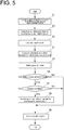
- FIG. 5 is a flowchart showing steps of the control method for the marine hybrid system 1 according to at least one embodiment of the present invention.
- the control device 25 includes a storage device 26 for storing various kinds of data needed to perform the control method to be described below, in particular, an output characteristic curve 40 of the thrust generation device 8 in each operation mode and fuel-efficiency map data 42 of the engine 2, a target output calculation part 28 for calculating a target output based on an operation state, an operation mode selection part 30 for selecting the operation mode of the marine hybrid system 1, an overload determination part 32 for determining whether the engine 2 is in an overload condition, and a control part 34 for controlling the marine hybrid system 1 based on the operation mode selected by the operation mode selection part 30 and a determination result of the overload determination part 32.
- These interior configurations of the control device 25 may be integrated or further divided.
- control device 25 accesses the storage device 26, acquiring the output characteristic curve 40 of the thrust generation device 8 in each operation mode and the fuel-efficiency map data 42 of the engine 2 stored in the storage device 26 (step S1).
- the storage device 26 stores the various kinds of data needed to perform the present control method, in particular, the output characteristic curve 40 of the thrust generation device 8 in each operation mode and the fuel-efficiency map data 42 of the engine 2.
- the output characteristic curve 40 defines rotation speed-output characteristics related to the thrust generation device 8 for each operation mode.
- the fuel-efficiency map data 42 defines a fuel consumption amount of the engine 2 relative to an operation parameter.
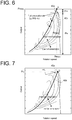
- FIGs. 6 to 8 are graphs showing the output characteristic curve 40 of the engine 2 in the motor assist mode, the engine drive mode, and the sailing power generation mode superimposed with the fuel-efficiency map data 42 of the engine 2.
- a maximum output Pmax is obtained at a maximum rotation speed Rmax (see an operation state A). That is, the maximum output Pmax is equal to addition of a maximum output Pm of the electric motor 4 to a maximum output Pe of the engine 2.
- the thrust generation device 8 of the ship is the propeller having a predetermined specification as described above, and the shape of the output characteristic curve is defined by a cubic curve uniformly decided in accordance with a specification thereof. That is, the output characteristic curve 40a in the motor assist mode shown in FIG. 6 is decided such that the cubic curve passes through the operation state A.
- the fuel-efficiency map data 42 of the engine 2 is indicated by contour lines to be superimposed with the output characteristic curve 40a in the motor assist mode.
- a fuel consumption rate is changed by transition of the operation state on the output characteristic curve 40a. More specifically, FIG. 6 shows that, for example, the fuel consumption rate of the engine 2 is higher in an operation state C than in operation state B.
- an output characteristic curve 40b of the engine 2 alone is indicated by a dashed line, for reference.
- the output characteristic curve 40b in the engine drive mode has a shape shifted to a low output side by the output of the electric motor 4, compared with the output characteristic curve 40a in the motor assist mode of FIG. 6 (in FIG. 7 , the output characteristic curve 40a in the motor assist mode is indicated by the dashed line, for comparison).
- the output characteristic curve 40b in the engine drive mode has the maximum output Pe at an intersection D with an output upper limit line 44 defining an operable range of the engine 2.
- the target output calculation part 28 acquires actual measured values of the boost pressure and the rotation speed, respectively, as the operation state of the ship (step S2), and calculates the target output of the ship based on the respective actual measured values of the boost pressure and the rotation speed (step S3). More specifically, the actual measured values of the boost pressure and the rotation speed are acquired by causing the control device 25 to access the boost pressure sensor 52 and the rotation speed sensor 54, respectively.
- the target output is calculated such that, for example, a target thrust by the propeller which corresponds to the lever opening degree detected by the lever opening degree sensor 60 is obtained, and an optimum output ratio of the engine 2 and the motor is obtained.
- a computation expression for calculating the target output may include correction calculation by the wind direction detected by the wind direction sensor 64 and the tide detected by the tide sensor 66.
- the operation mode selection part 30 applies the target output calculated in step S3 to the output characteristic curve 40 corresponding to each operation mode acquired in step S1, thereby obtaining an estimated value of the fuel consumption rate in each operation mode (step S4). That is, based on the output characteristic curve 40 in the operation mode shown in each of FIGs. 6 to 8 , the fuel consumption rate assumed if the operation is performed in each operation mode is estimated.
- the operation mode selection part 30 compares the estimated values of the fuel consumption rate in the respective operation modes obtained in step S4, thereby selecting the operation mode with the highest fuel consumption rate (step S5). Thus, it is possible to select the operation mode capable of implementing the good fuel consumption rate in accordance with the operation condition, even if there are the plurality of operation modes.
- Step S5 of the present embodiment illustrates the case in which the operation mode is selected based on the fuel consumption rate when sailing with an emphasis on the fuel consumption rate is done.
- an operation mode giving priority to a sailing speed may be selected, or an operation mode giving priority to ensuring the state of charge of the battery 6 may be selected.
- a selection criteria of the operation mode may be set in accordance with the sailing condition.
- the selection criteria of the operation mode may be changeable in accordance with entry of the operator.
- step S6 determines whether the operation mode selected in step S5 is the sailing power generation mode. If the operation mode is the sailing power generation mode (step S6: YES), the overload determination part 32 determines whether the engine 2 is in the overload condition (step S7).
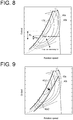
- the power output from the engine 2 is used to drive the thrust generation device 8 and to regeneratively drive the electric motor 4. If the load Pr by regenerative drive of the electric motor 4 is larger than the drive load Pm of the electric motor 4 in the motor assist mode, the engine 2 may be brought into the overload condition. That is, as shown in FIG. 8 , if the power generation load of the electric motor 4 is larger than a predetermined value (the maximum output of the electric motor 4 in power drive), the output characteristic curve 40c in the sailing power generation mode is positioned on a high output side, relative to the output characteristic curve 40a in the motor assist mode.
- a predetermined value the maximum output of the electric motor 4 in power drive
- step S7 YES
- the control part 34 controls the clutch mechanism 10 to change the power path in the second clutches 16 from the first path 16a to the second path 16b (step S8). That is, switching the power path from the first path 16a on the low gear side to the second path 16b on the high gear side, the load of the engine 2 is reduced, eliminating the overload condition.
- FIG. 9 is a graph showing a change in output characteristics by switching of the power path in the second clutches 16 in step S8 of FIG. 5 .
- FIG. 9 shows an output characteristic curve 40c1 in the case in which the first path 16a is selected in the second clutches 16, and a state in which the output characteristic curve 40c1 shifts to an output characteristic curve 40c2 if the power path is changed from the first path 16a to the second path 16b in the second clutches 16 in step S8. It is found that the second path 16b is set to have the transmission ratio lower than that of the first path 16a, and thus shifts to the low output side.
- the power path is switched to the second path 16b if it is determined in step S8 that the engine 2 is in the overload condition. Consequently, an output characteristic curve 40a1 is shifted to the low output side and changed to an output characteristic curve 40a2. With a decrease in transmission ratio, the output characteristic curve 40a2 moves to the low output side relative to the output characteristic curve 40a in the motor assist mode, eliminating the overload condition.
- At least one embodiment of the present invention is available for a marine hybrid system that can be equipped with a hybrid propulsion ship including an engine and an electric motor as power sources, and a control method for the marine hybrid system.
Landscapes
- Chemical & Material Sciences (AREA)
- Engineering & Computer Science (AREA)
- Combustion & Propulsion (AREA)
- Mechanical Engineering (AREA)
- Ocean & Marine Engineering (AREA)
- Hybrid Electric Vehicles (AREA)
- Control Of Vehicle Engines Or Engines For Specific Uses (AREA)
Abstract
Description
- The present disclosure relates to a marine hybrid system that can be equipped with a hybrid propulsion ship including an engine and an electric motor as power sources, and a control method for the marine hybrid system.
- In a ship sailing on water, a thrust for sailing is obtained by driving a thrust generation device such as a propeller by a power source. Conventionally, an engine which is an internal combustion engine consuming a fossil fuel has mainly been used as the power source. Recently, however, in order to reduce a fuel consumption amount and an environmental load, development of a so-called hybrid propulsion ship is advanced which includes, in addition to the conventional engine, an electric motor (electric motor drive) that can be driven by using electric energy stored in a battery or the like.
- In the hybrid propulsion ship, individually controlling the two power sources, that is, the engine and the electric motor, an operation is performed while selectively controlling a plurality of operation modes in accordance with sailing conditions. For example,
Patent Document 1 discloses an example of the hybrid propulsion ship. In the above ship, it is possible to select an engine drive mode in which a thrust is obtained by driving only the engine, a motor drive mode in which a thrust is obtained by driving only the electric motor, and a motor assist mode in which a thrust is obtained by driving both of the engine and the electric motor. - Patent Document 1:
JP2013-147186A - As an engine used in a ship, a mechanical engine prevails which can adjust an output obtained by control of a rotations peed, by manually performing a throttle operation by an operator. The mechanical engine is operated by, for example, grasping a rotation speed-output characteristics of the engine in advance, and controlling the rotation speed by the throttle operation in consideration of a wind direction and a tide. Also in a hybrid ship including an engine and an electric motor as power sources, a mechanical engine is often used as the engine, like the conventional ship. However, in the hybrid ship, with the two power sources, that is, the engine and the electric motor, the operator is required of not only the throttle operation of the engine but also selection of the operation mode as in
Patent Document 1 above. That is, in the hybrid ship, although good fuel economy performance is advantageously obtained by switching the operation modes while combining the engine and the electric motor in accordance with the sailing condition, it is difficult to perform engine control by the throttle operation while appropriately switching the operation modes with the mechanical engine, and the fuel economy performance by hybrid may not sufficiently be delivered. - Moreover, in the hybrid propulsion ship, in addition to the three operation modes described in
Patent Document 1, for example, a sailing power generation mode in which power is generated by the electric motor with a part of power of the engine while obtaining a thrust by driving the engine, and a stop power generation mode in which power is generated by driving the electric motor with the power of the engine while the ship is stopped are considered. In these operation modes, electric energy can be supplied by regeneratively driving the electric motor, which is effective in improving energy efficiency of the ship. However, in the sailing power generation mode, if a power generation load of the electric motor increases, the engine may be brought into an overload condition depending on a sailing condition. Bringing the engine into the overload condition, various defects such as excessive wear, oil deterioration, and seizure are carried, and a failure may be caused if the defects further advance. - At least one embodiment of the present invention is made in view of the above, and an object of the present invention is to provide a marine hybrid system capable of appropriately performing drive control of the engine and the electric motor in accordance with the sailing condition while preventing the engine from being brought into the overload condition, and a control method for the marine hybrid system.
- (1) In order to solve the above-described problems, a marine hybrid system according to at least one embodiment of the present invention includes an engine, an electric motor, a thrust generation device capable of generating a thrust of a ship by using an output of at least one of the engine or the electric motor, a clutch mechanism configured to be able to switch connection states between the engine, the electric motor, and the thrust generation device, an overload determination part for determining whether the engine is in an overload condition, and a control device for controlling a connection state of the clutch mechanism. The control device controls the clutch mechanism such that a load of the engine is reduced, if the overload determination part determines that the engine is in the overload condition.
- With the above configuration (1), controlling the clutch mechanism such that the load of the engine is reduced, if it is determined that the engine is in the overload condition, it is possible to adequately preventing the engine from being brought into the overload condition. As a result, it is possible to implement the marine hybrid system capable of stable operation with high reliability.
- (2) In some embodiments, in the above configuration (1), the overload determination part determines whether the engine is in the overload condition in a sailing power generation mode where power is generated by the electric motor during sailing by supplying the output of the engine to the thrust generation device and the electric motor.
- With the above configuration (2), controlling the clutch mechanism such that the load is reduced when the engine is brought into the overload condition in the sailing power generation mode where the output of the engine is used not only for a thrust force for sailing but also for power generation of the electric motor, it is possible to adequately prevent the engine from being brought into the overload condition.
- (3) In some embodiments, in the above configuration (1) or (2), the clutch mechanism includes a first clutch disposed between the thrust generation device and an intermediate shaft, second clutches disposed between the intermediate shaft and the engine, and a third clutch disposed between the intermediate shaft and the drive motor, the second clutches are disposed in parallel, and include a power transmission path including a first path and a second path different from each other in transmission ratio, and the control device is configured to be able to adjust the load of the engine by alternatively switching the first path or the second path, if the second clutches are connected.
- With the above configuration (3), the power transmission path connected to the engine includes the first path and the second path. The first path and the second path are configured to be different from each other in transmission ratio, and are switched if the overload condition is determined, making it possible to reduce the load of the engine.
- (4) In some embodiments, in the above configuration (3), the second path is set to have the transmission ratio lower than that of the first path, and the control device controls the clutch mechanism such that the power transmission path of the second clutches is switched from the first path to the second path, if the overload determination part determines that the internal combustion engine is in the overload condition.
- With the above configuration (4), if the overload condition is determined, in the second clutches, the power transmission path is switched from the first path having the higher transmission ratio to the second path having the lower transmission ratio, making it possible to reduce the load of the engine.
- (5) In some embodiments, in any one of the above configurations (1) to (4), the ship has a plurality of operation modes, the plurality of operation modes include an engine drive mode in which the ship sails by power of the engine, a motor drive mode in which the ship sails by power of the electric motor, a motor assist mode in which the ship sails by power of both of the engine and the electric motor, a sailing power generation mode in which power is generated by the electric motor while the ship sails by the power of the engine, and a stop power generation mode in which power is generated by the electric motor while the thrust power generation device is stopped, and the control device controls the clutch mechanism such that the load of the engine is reduced, if the overload determination part determines that the engine is in the overload condition, in the sailing power generation mode of the operation modes.
- With the above configuration (5), the ship has the engine drive mode, the motor drive mode, the motor assist mode, the sailing power generation mode, and the stop power generation mode. Then, if the engine is brought into the overload condition by an increase in load needed for regenerative drive of the electric motor in the sailing power generation mode of these five operation modes, controlling the clutch mechanism such that the load of the engine is reduced as described above, it is possible to adequately prevent the engine from being brought into the overload condition.
- (6) In some embodiments, in the above configuration (5), the marine hybrid system further includes a storage device for storing an output characteristic curve defining a relationship between a rotation speed and an output of the thrust generation device in each of the plurality of operation modes, and fuel-efficiency map data of the engine, a target output calculation part for calculating a target output of the thrust generation device, and an operation mode selection part for calculating, based on the output characteristic curve and fuel map data, a fuel consumption rate in each of the operation modes corresponding to the target output, and selecting, based on the fuel consumption rate in each of the operation modes, the operation mode to be implemented.
- With the above configuration (6), based on the output characteristic curve and the fuel-efficiency map data prestored in the storage device, a fuel consumption rate in each operation mode relative to the target output of the ship is calculated. Then, comparing the fuel consumption rates assumed in the respective operation modes, it is possible to implement efficient sailing while selecting the optimum operation mode. In particular, if the fuel consumption rate is given priority, performing the above-described control, it is possible to switch the operation modes so that the optimum fuel consumption rate is obtained.
- (7) In some embodiments, in any one of the above configurations (1) to (6), the engine is a mechanical engine capable of controlling a rotation speed by a throttle operation of an operator.
- With the above configuration (7), also in the mechanical engine capable of controlling the rotation speed by the throttle operation of the operator, preventing the engine from being brought into the overload condition, stable operation is enabled at high reliability.
- (8) In order to solve the above-described problems, a control method for a marine hybrid system, which includes an engine, an electric motor, a thrust generation device capable of generating a thrust of a ship by using an output of at least one of the engine or the electric motor, and a clutch mechanism configured to be able to switch connection states between the engine, the electric motor, and the thrust generation device, according to at least one embodiment of the present invention, includes an overload determination step of determining whether the engine is in an overload condition, and a control step of controlling the clutch mechanism such that a load of the engine is reduced, if it is determined that the engine is in the overload condition.
- With the above method (8), controlling the clutch mechanism such that the load of the engine is reduced, if it is determined that the engine is in the overload condition, it is possible to adequately prevent the engine from being brought into the overload condition. As a result, it is possible to implement the marine hybrid system capable of stable operation with high reliability.
- (9) In some embodiments, in the above method (8), the control step includes determining whether the engine is in the overload condition in a sailing power generation mode where power is generated by the electric motor during sailing by supplying the output of the engine to the thrust generation device and the electric motor.
- With the above method (9), controlling the clutch mechanism such that the load is reduced when the engine is brought into the overload condition in the sailing power generation mode where the output of the engine is used not only for a thrust force for sailing but also for power generation of the electric motor, it is possible to adequately prevent the engine from being brought into the overload condition.
- According to at least one embodiment of the present invention, it is possible to provide a marine hybrid system capable of appropriately performing drive control of an engine and an electric motor in accordance with a sailing condition while preventing the engine from being brought into an overload condition, and a control method for the marine hybrid system.
-
-
FIG. 1 is an overall configuration diagram of a marine hybrid system according to at least one embodiment of the present invention. -
FIG. 2 is a detailed diagram of second clutches inFIG. 1 . -
FIG. 3 is a list showing connection states of a first clutch, the second clutches, and a third clutch, and drive states of an engine and an electric motor in respective operation modes. -
FIG. 4 is a block diagram showing the internal configuration of a control device inFIG. 1 , together with a peripheral configuration. -
FIG. 5 is a flowchart showing steps of a control method for the marine hybrid system according to at least one embodiment of the present invention. -
FIG. 6 is a graph showing an output characteristic curve of the engine in a motor assist mode superimposed with fuel-efficiency map data of the engine. -
FIG. 7 is a graph showing an output characteristic curve of the engine in an engine drive mode superimposed with the fuel-efficiency map data of the engine. -
FIG. 8 is a graph showing an output characteristic curve of the engine in a sailing power generation mode superimposed with the fuel-efficiency map data of the engine. -
FIG. 9 is a graph showing a change in output characteristics by switching of a power path in the second clutches in step S8 ofFIG. 5 . - Some embodiments of the present invention will be described below with reference to the accompanying drawings. It is intended, however, that unless particularly identified, dimensions, materials, shapes, relative positions and the like of components described or shown in the drawings as the embodiments shall be interpreted as illustrative only and not intended to limit the scope of the present invention.
-
FIG. 1 is an overall configuration diagram of amarine hybrid system 1 according to at least one embodiment of the present invention. Themarine hybrid system 1 includes anengine 2 and anelectric motor 4 as power sources of a ship sailing on water. Theengine 2 is an internal combustion engine capable of outputting power by consuming a fossil fuel. Theelectric motor 4 is an electric motor drive capable of outputting power by being driven (power-driven) by power (electric energy) stored in abattery 6 mounted on the ship. Moreover, theelectric motor 4 can function as a generator by being mechanically driven (regeneratively driven) from outside. In this case, power generated by theelectric motor 4 is stored in thebattery 6. - Although not shown in
FIG. 1 , various power conversion elements such as an inverter and a converter may be disposed on an electric path between theelectric motor 4 and thebattery 6. - A
thrust generation device 8 is a device for generating a thrust for sailing of the ship by being driven by power output from at least one of theengine 2 or theelectric motor 4. Thethrust generation device 8 is, for example, a propeller. - The
thrust generation device 8 is connected to theengine 2 and theelectric motor 4 via aclutch mechanism 10. Thus, in accordance with a connection state of theclutch mechanism 10, at least one of theengine 2 or theelectric motor 4 is connected to thethrust generation device 8 in terms of power. As a result, the ship obtains the thrust by driving thethrust generation device 8 by using the output of at least one of theengine 2 or theelectric motor 4. - The
clutch mechanism 10 is configured to be able to switch connection states between theengine 2, theelectric motor 4, and thethrust generation device 8. As shown inFIG. 1 , theclutch mechanism 10 includes a first clutch 14 configured to be able to disconnect anintermediate shaft 12 and aninput shaft 8a of thethrust generation device 8,second clutches 16 configured to be able to disconnect theintermediate shaft 12 and theengine 2, and a third clutch 18 configured to be able to disconnect theintermediate shaft 12 and theelectric motor 4. The above-described first clutch 14,second clutches 16 and third clutch 18 are configured to be able to connect/disconnect theengine 2, theelectric motor 4, and thethrust generation device 8 in terms of power, by switching respective connection states. -
FIG. 2 is a detailed diagram of thesecond clutches 16 inFIG. 1 . As shown inFIG. 2 , thesecond clutches 16 disposed between theengine 2 and theintermediate shaft 12 include afirst path 16a and asecond path 16b disposed in parallel. Thefirst path 16a and thesecond path 16b include afirst subclutch 17a and asecond subclutch 17b, respectively, and are configured to be independently connectable. - The
first path 16a and thesecond path 16b include atransmission mechanism 19 on a side of theengine 2. Thetransmission mechanism 19 includes afirst gear 20a disposed at an end of thefirst path 16a, asecond gear 20b disposed at an end of thesecond path 16b, and athird gear 20c disposed on the side of an output shaft of theengine 2. Thefirst gear 20a, thesecond gear 20b, and thethird gear 20c are set to each have a predetermined transmission ratio when power is transmitted in thefirst path 16a and thesecond path 16b. - The
first gear 20a, thesecond gear 20b, and thethird gear 20c are set to have different transmission ratios in thefirst path 16a and thesecond path 16b. In the present embodiment, thesecond path 16b is set to have a lower transmission ratio than that of thefirst path 16a (in other words, thefirst path 16a has a low gear, and thesecond path 16b has a high gear). - In a case in which the
second clutches 16 are switched into a connected state by acontrol device 25 to be described later, control is performed such that thefirst path 16a is selected first as default (thefirst subclutch 17a enters a connected state, and thesecond subclutch 17b enters a disconnected state), and if a predetermined condition is satisfied (step S7 inFIG. 5 to be described later: YES), thesecond path 16b is selected (thefirst subclutch 17a enters the disconnected state, and thesecond subclutch 17b enters the connected state). - Referring back to
FIG. 1 , themarine hybrid system 1 includes thecontrol device 25. Thecontrol device 25 is configured as a control unit for themarine hybrid system 1 by including hardware constituted by an electronic computation device such as a computer and installing, on the hardware, a program for performing the control method for themarine hybrid system 1 according to at least one embodiment of the present invention. The program can be installed by reading, for example, a program stored in a predetermined storage medium with a reading device of the hardware, and the program and the storage medium storing the program also fall within the technical scope of the present invention. - The
control device 25 controls themarine hybrid system 1 by transmitting/receiving various control signals to the respective constituent elements of themarine hybrid system 1. InFIG. 1 , flows of the control signals are representatively indicated by dashed lines, respectively, in a range necessary for the following description. - In the present embodiment, the
control device 25 causes theengine 2, theelectric motor 4, and theclutch mechanism 10 to cooperate each other, thereby configuring such that five operation modes can be performed. The five operation modes include an engine drive mode, a motor drive mode, a motor assist mode, a sailing power generation mode, and a stop power generation mode.FIG. 3 is a list showing connection states of the first clutch 14, thesecond clutches 16, and the third clutch 18, and drive states of theengine 2 and theelectric motor 4 in the respective operation modes. - The engine drive mode is the operation mode in which the thrust for sailing is generated by driving the
thrust generation device 8 only by theengine 2. At this time, as shown in (a) ofFIG. 3 , the first clutch 14 and thesecond clutches 16 are set in the connected state, and the third clutch is set in the disconnected state. Thus, theengine 2 and thethrust generation device 8 are connected in terms of power, and theelectric motor 4 is disconnected in terms of power from theengine 2 and thethrust generation device 8. Then, power output from theengine 2 serving as the power source is transmitted to thethrust generation device 8 via theclutch mechanism 10, obtaining a thrust force of the ship. At this time, theelectric motor 4 is in a stopped state (disconnected in terms of power, theelectric motor 4 may be driven; however, theelectric motor 4 is preferably in the stopped state in order to avoid wasteful electric power consumption). - The motor drive mode is the operation mode in which the thrust for sailing is generated by driving the
thrust generation device 8 only by theelectric motor 4. At this time, as shown in (b) ofFIG. 3 , the first clutch 14 and the third clutch 18 are set in the connected state, and thesecond clutches 16 are set in the disconnected state. Thus, theelectric motor 4 and thethrust generation device 8 are connected in terms of power, and theengine 2 is disconnected in terms of power from theelectric motor 4 and thethrust generation device 8. Then, power output from theelectric motor 4 serving as the power source is transmitted to thethrust generation device 8 via theclutch mechanism 10, obtaining a thrust force of the ship. At this time, theengine 2 is in the stopped state (disconnected in terms of power, theengine 2 may be driven; however, theengine 2 is preferably in the stopped state in order to avoid wasteful fuel consumption). - The motor assist mode is the operation mode in which the thrust for sailing is generated by driving the
thrust generation device 8 by both of theengine 2 and theelectric motor 4. At this time, as shown in (c) ofFIG. 3 , the first clutch 14, thesecond clutches 16, and the third clutch 18 are all set in the connected state. Thus, theengine 2, theelectric motor 4, and thethrust generation device 8 are connected to each other in terms of power. Then, power output from theengine 2 and theelectric motor 4 each serving as the power source is transmitted to thethrust generation device 8 via theclutch mechanism 10, obtaining a thrust force of the ship. - The sailing power generation mode is the operation mode in which the thrust for sailing is generated by the output of the
engine 2 supplied to theelectric motor 4 and thethrust generation device 8, and power is generated by regeneratively driving theelectric motor 4 by using a part of the output of theengine 2. At this time, as shown in (d) ofFIG. 3 , the first clutch 14, thesecond clutches 16, and the third clutch 18 are all set in the connected state. Thus, theengine 2, theelectric motor 4, and thethrust generation device 8 are connected to each other in terms of power. Then, the power output from theengine 2 serving as the power source is transmitted to theelectric motor 4 and thethrust generation device 8 via theclutch mechanism 10. Thus, a thrust force of the ship is obtained in thethrust generation device 8, and power is generated by regeneratively driving theelectric motor 4. At this time, the power generated in theelectric motor 4 may be stored in thebattery 6 or may directly be supplied to an inboard load. - The stop power generation mode is the operation mode in which power is generated by supplying the output of the
engine 2 to theelectric motor 4, thereby regeneratively driving theelectric motor 4 by the output of theengine 2 in the ship in the stopped state. At this time, as shown in (e) ofFIG. 3 , thesecond clutches 16 and the third clutch 18 are set in the connected state, and the first clutch 14 is set in the disconnected state. Thus, theengine 2 and theelectric motor 4 are connected to each other in terms of power. Then, the power output from theengine 2 serving as the power source is transmitted to theelectric motor 4 via theclutch mechanism 10, without being transmitted to thethrust generation device 8. Thus, theelectric motor 4 is regeneratively driven, generating power. At this time, the power generated in theelectric motor 4 may be stored in thebattery 6 or may directly be supplied to the inboard load. - Moreover, as shown in
FIG. 1 , themarine hybrid system 1 includes various sensors for monitoring the states of the constituent elements, respectively. More specifically, themarine hybrid system 1 includes aboost pressure sensor 52 for detecting a boost pressure of a supercharger (not shown) of theengine 2, arotation speed sensor 54 for detecting a rotation speed of theengine 2, a battery state ofcharge sensor 56 for detecting a State of Charge (SOC) of thebattery 6, a degree ofbattery deterioration sensor 58 for detecting the degree of deterioration of thebattery 6, a leveropening degree sensor 60 for detecting an opening degree of a throttle lever to be operated when a user performs throttle control on theengine 2, aGPS sensor 62 for detecting positional information of the ship, awind direction sensor 64 for detecting a wind direction, and atide sensor 66 for detecting a tide. These various sensors are connected to thecontrol device 25 via a communication line and in thecontrol device 25, it is possible to perform control based on detection results acquired from the respective sensors. -
FIG. 4 is a block diagram showing an interior configuration of thecontrol device 25 inFIG. 1 , together with a peripheral configuration.FIG. 5 is a flowchart showing steps of the control method for themarine hybrid system 1 according to at least one embodiment of the present invention. - As shown in
FIG. 4 , thecontrol device 25 includes astorage device 26 for storing various kinds of data needed to perform the control method to be described below, in particular, an outputcharacteristic curve 40 of thethrust generation device 8 in each operation mode and fuel-efficiency map data 42 of theengine 2, a targetoutput calculation part 28 for calculating a target output based on an operation state, an operationmode selection part 30 for selecting the operation mode of themarine hybrid system 1, anoverload determination part 32 for determining whether theengine 2 is in an overload condition, and acontrol part 34 for controlling themarine hybrid system 1 based on the operation mode selected by the operationmode selection part 30 and a determination result of theoverload determination part 32. These interior configurations of thecontrol device 25 may be integrated or further divided. - In the control method for the
marine hybrid system 1, first, thecontrol device 25 accesses thestorage device 26, acquiring the outputcharacteristic curve 40 of thethrust generation device 8 in each operation mode and the fuel-efficiency map data 42 of theengine 2 stored in the storage device 26 (step S1). - The
storage device 26 stores the various kinds of data needed to perform the present control method, in particular, the outputcharacteristic curve 40 of thethrust generation device 8 in each operation mode and the fuel-efficiency map data 42 of theengine 2. The outputcharacteristic curve 40 defines rotation speed-output characteristics related to thethrust generation device 8 for each operation mode. The fuel-efficiency map data 42 defines a fuel consumption amount of theengine 2 relative to an operation parameter.FIGs. 6 to 8 are graphs showing the outputcharacteristic curve 40 of theengine 2 in the motor assist mode, the engine drive mode, and the sailing power generation mode superimposed with the fuel-efficiency map data 42 of theengine 2. - First, focusing on an output
characteristic curve 40a in the motor assist mode shown inFIG. 6 , in the motor assist mode, since both of theengine 2 and theelectric motor 4 are used as the power sources, respectively, a maximum output Pmax is obtained at a maximum rotation speed Rmax (see an operation state A). That is, the maximum output Pmax is equal to addition of a maximum output Pm of theelectric motor 4 to a maximum output Pe of theengine 2. Moreover, thethrust generation device 8 of the ship is the propeller having a predetermined specification as described above, and the shape of the output characteristic curve is defined by a cubic curve uniformly decided in accordance with a specification thereof. That is, the outputcharacteristic curve 40a in the motor assist mode shown inFIG. 6 is decided such that the cubic curve passes through the operation state A. - In
FIG. 6 , the fuel-efficiency map data 42 of theengine 2 is indicated by contour lines to be superimposed with the outputcharacteristic curve 40a in the motor assist mode. Thus, it is found that a fuel consumption rate is changed by transition of the operation state on the outputcharacteristic curve 40a. More specifically,FIG. 6 shows that, for example, the fuel consumption rate of theengine 2 is higher in an operation state C than in operation state B. - In
FIG. 6 , an outputcharacteristic curve 40b of theengine 2 alone is indicated by a dashed line, for reference. - Subsequently, focusing on the output
characteristic curve 40b in the engine drive mode shown inFIG. 7 , in the engine drive mode, since only theengine 2 is used as the power source, the outputcharacteristic curve 40b in the engine drive mode has a shape shifted to a low output side by the output of theelectric motor 4, compared with the outputcharacteristic curve 40a in the motor assist mode ofFIG. 6 (inFIG. 7 , the outputcharacteristic curve 40a in the motor assist mode is indicated by the dashed line, for comparison). Moreover, the outputcharacteristic curve 40b in the engine drive mode has the maximum output Pe at an intersection D with an outputupper limit line 44 defining an operable range of theengine 2. - Subsequently, focusing on an output
characteristic curve 40c in the sailing power generation mode shown inFIG. 8 , in the sailing power generation mode, although only theengine 2 is used as the power source, both of theelectric motor 4 and thethrust generation device 8 are connected to a load side. Thus, the output characteristics shown inFIG. 8 are addition of a power generation load Pr caused in regenerative drive of theelectric motor 4 to the outputcharacteristic curve 40b in the engine drive mode described above with reference toFIG. 7 (inFIG. 8 , the outputcharacteristic curve 40a in the motor assist mode and the outputcharacteristic curve 40b in the engine drive mode are indicated by dotted lines, respectively, for comparison). - Next, the target
output calculation part 28 acquires actual measured values of the boost pressure and the rotation speed, respectively, as the operation state of the ship (step S2), and calculates the target output of the ship based on the respective actual measured values of the boost pressure and the rotation speed (step S3). More specifically, the actual measured values of the boost pressure and the rotation speed are acquired by causing thecontrol device 25 to access theboost pressure sensor 52 and therotation speed sensor 54, respectively. The target output is calculated such that, for example, a target thrust by the propeller which corresponds to the lever opening degree detected by the leveropening degree sensor 60 is obtained, and an optimum output ratio of theengine 2 and the motor is obtained. At this time, a computation expression for calculating the target output may include correction calculation by the wind direction detected by thewind direction sensor 64 and the tide detected by thetide sensor 66. - Subsequently, the operation
mode selection part 30 applies the target output calculated in step S3 to the outputcharacteristic curve 40 corresponding to each operation mode acquired in step S1, thereby obtaining an estimated value of the fuel consumption rate in each operation mode (step S4). That is, based on the outputcharacteristic curve 40 in the operation mode shown in each ofFIGs. 6 to 8 , the fuel consumption rate assumed if the operation is performed in each operation mode is estimated. - Then, the operation
mode selection part 30 compares the estimated values of the fuel consumption rate in the respective operation modes obtained in step S4, thereby selecting the operation mode with the highest fuel consumption rate (step S5). Thus, it is possible to select the operation mode capable of implementing the good fuel consumption rate in accordance with the operation condition, even if there are the plurality of operation modes. - Step S5 of the present embodiment illustrates the case in which the operation mode is selected based on the fuel consumption rate when sailing with an emphasis on the fuel consumption rate is done. However, for example, an operation mode giving priority to a sailing speed may be selected, or an operation mode giving priority to ensuring the state of charge of the
battery 6 may be selected. Thus, a selection criteria of the operation mode may be set in accordance with the sailing condition. In this case, the selection criteria of the operation mode may be changeable in accordance with entry of the operator. - Subsequently, the
control device 25 determines whether the operation mode selected in step S5 is the sailing power generation mode (step S6). If the operation mode is the sailing power generation mode (step S6: YES), theoverload determination part 32 determines whether theengine 2 is in the overload condition (step S7). - As mentioned above with reference to
FIG. 8 , in the sailing power generation mode, the power output from theengine 2 is used to drive thethrust generation device 8 and to regeneratively drive theelectric motor 4. If the load Pr by regenerative drive of theelectric motor 4 is larger than the drive load Pm of theelectric motor 4 in the motor assist mode, theengine 2 may be brought into the overload condition. That is, as shown inFIG. 8 , if the power generation load of theelectric motor 4 is larger than a predetermined value (the maximum output of theelectric motor 4 in power drive), the outputcharacteristic curve 40c in the sailing power generation mode is positioned on a high output side, relative to the outputcharacteristic curve 40a in the motor assist mode. This means that the load which exceeds the output characteristics in the motor assist mode defining the maximum output is imposed on theengine 2, and theengine 2 is in the overload condition. Thus bringing theengine 2 into the overload condition, various defects such as excessive wear, oil deterioration, and seizure are carried, and a failure may be caused if the defects further advance. - Thus, if it is determined that the
engine 2 is in the overload condition in the sailing power generation mode (step S7: YES), thecontrol part 34 controls theclutch mechanism 10 to change the power path in thesecond clutches 16 from thefirst path 16a to thesecond path 16b (step S8). That is, switching the power path from thefirst path 16a on the low gear side to thesecond path 16b on the high gear side, the load of theengine 2 is reduced, eliminating the overload condition. -
FIG. 9 is a graph showing a change in output characteristics by switching of the power path in thesecond clutches 16 in step S8 ofFIG. 5 .FIG. 9 shows an output characteristic curve 40c1 in the case in which thefirst path 16a is selected in thesecond clutches 16, and a state in which the output characteristic curve 40c1 shifts to an output characteristic curve 40c2 if the power path is changed from thefirst path 16a to thesecond path 16b in thesecond clutches 16 in step S8. It is found that thesecond path 16b is set to have the transmission ratio lower than that of thefirst path 16a, and thus shifts to the low output side. - In the
second clutches 16, set in the connected state by thecontrol device 25, although thefirst path 16a having the higher transmission ratio is selected as default, the power path is switched to thesecond path 16b if it is determined in step S8 that theengine 2 is in the overload condition. Consequently, an output characteristic curve 40a1 is shifted to the low output side and changed to an output characteristic curve 40a2. With a decrease in transmission ratio, the output characteristic curve 40a2 moves to the low output side relative to the outputcharacteristic curve 40a in the motor assist mode, eliminating the overload condition. - As described above, according to the present embodiment, controlling the clutch mechanism such that the load of the engine is reduced, if it is determined that the engine is in the overload condition, it is possible to adequately prevent the engine from being brought into the overload condition. As a result, it is possible to implement the marine hybrid system capable of stable operation with high reliability.
- At least one embodiment of the present invention is available for a marine hybrid system that can be equipped with a hybrid propulsion ship including an engine and an electric motor as power sources, and a control method for the marine hybrid system.
-
- 1
- Marine hybrid system
- 2
- Engine
- 4
- Electric motor
- 6
- Battery
- 8
- Thrust generation device
- 10
- Clutch mechanism
- 14
- First clutch
- 16
- Second clutch
- 18
- Third clutch
- 19
- Transmission mechanism
- 25
- Control device
- 26
- Storage device
- 28
- Target output calculation part
- 30
- Operation mode selection part
- 32
- Overload determination part
- 34
- Control part
- 40
- Output characteristic curve
- 42
- Fuel-efficiency map data
- 44
- Output upper limit line
- 52
- Boost pressure sensor
- 54
- Rotation speed sensor
- 56
- Battery state of charge sensor
- 58
- Degree of battery deterioration sensor
- 60
- Lever opening degree sensor
- 62
- GPS sensor
- 64
- Wind direction sensor
- 66
- Tide sensor
Claims (9)
- A marine hybrid system, comprising:an engine;an electric motor;a thrust generation device capable of generating a thrust of a ship by using an output of at least one of the engine or the electric motor;a clutch mechanism configured to be able to switch connection states between the engine, the electric motor, and the thrust generation device;an overpower determination part for determining whether the engine is in an overload condition; anda control device for controlling a connection state of the clutch mechanism,wherein the control device controls the clutch mechanism such that a load of the engine is reduced, if the overload determination part determines that the engine is in the overload condition.
- The marine hybrid system according to claim 1,
wherein the overload determination part determines whether the engine is in the overload condition in a sailing power generation mode where power is generated by the electric motor during sailing by supplying the output of the engine to the thrust generation device and the electric motor. - The marine hybrid system according to claim 1 or 2,
wherein the clutch mechanism includes:a first clutch disposed between the thrust generation device and an intermediate shaft;second clutches disposed between the intermediate shaft and the engine; anda third clutch disposed between the intermediate shaft and the drive motor,wherein the second clutches are disposed in parallel, and include a power transmission path including a first path and a second path different from each other in transmission ratio, andwherein the control device is configured to be able to adjust the load of the engine by alternatively switching the first path or the second path, if the second clutches are connected. - The marine hybrid system according to claim 3,
wherein the second path is set to have the transmission ratio lower than that of the first path, and
wherein the control device controls the clutch mechanism such that the power transmission path of the second clutches is switched from the first path to the second path, if the overload determination part determines that the internal combustion engine is in the overload condition. - The marine hybrid system according to any one of claims 1 to 4,
wherein the ship has a plurality of operation modes,
wherein the plurality of operation modes include:an engine drive mode in which the ship sails by power of the engine;a motor drive mode in which the ship sails by power of the electric motor;a motor assist mode in which the ship sails by power of both of the engine and the electric motor;a sailing power generation mode in which power is generated by the electric motor while the ship sails by the power of the engine; anda stop power generation mode in which power is generated by the electric motor while the thrust power generation device is stopped, andwherein the control device controls the clutch mechanism such that the load of the engine is reduced, if the overload determination part determines that the engine is in the overload condition, in the sailing power generation mode of the operation modes. - The marine hybrid system according to claim 5, further comprising:a storage device for storing an output characteristic curve defining a relationship between a rotation speed and an output of the thrust generation device in each of the plurality of operation modes, and fuel-efficiency map data of the engine;a target output calculation part for calculating a target output of the thrust generation device; andan operation mode selection part for calculating, based on the output characteristic curve and fuel map data, a fuel consumption rate in each of the operation modes corresponding to the target output, and selecting, based on the fuel consumption rate in each of the operation modes, the operation mode to be implemented.
- The marine hybrid system according to any one of claims 1 to 6,
wherein the engine is a mechanical engine capable of controlling a rotation speed by a throttle operation of an operator. - A control method for a marine hybrid system which includes:an engine;an electric motor;a thrust generation device capable of generating a thrust of a ship by using an output of at least one of the engine or the electric motor; anda clutch mechanism configured to be able to switch connection states between the engine, the electric motor, and the thrust generation device, the method comprising:an overload determination step of determining whether the engine is in an overload condition; anda control step of controlling the clutch mechanism such that a load of the engine is reduced, if it is determined that the engine is in the overload condition.
- The control method for the marine hybrid system according to claim 8,
wherein the control step includes determining whether the engine is in the overload condition in a sailing power generation mode where power is generated by the electric motor during sailing by supplying the output of the engine to the thrust generation device and the electric motor.
Applications Claiming Priority (2)
| Application Number | Priority Date | Filing Date | Title |
|---|---|---|---|
| JP2018192051A JP7221017B2 (en) | 2018-10-10 | 2018-10-10 | Marine hybrid system and control method for marine hybrid system |
| PCT/JP2019/033773 WO2020075408A1 (en) | 2018-10-10 | 2019-08-28 | Hybrid system for ship and control method for hybrid system for ship |
Publications (2)
| Publication Number | Publication Date |
|---|---|
| EP3865394A1 true EP3865394A1 (en) | 2021-08-18 |
| EP3865394A4 EP3865394A4 (en) | 2021-12-08 |
Family
ID=70164290
Family Applications (1)
| Application Number | Title | Priority Date | Filing Date |
|---|---|---|---|
| EP19870475.1A Pending EP3865394A4 (en) | 2018-10-10 | 2019-08-28 | HYBRID SYSTEM FOR SHIPS AND CONTROL PROCEDURES FOR A HYBRID SYSTEM FOR SHIPS |
Country Status (5)
| Country | Link |
|---|---|
| US (1) | US11753130B2 (en) |
| EP (1) | EP3865394A4 (en) |
| JP (1) | JP7221017B2 (en) |
| CN (1) | CN112752711B (en) |
| WO (1) | WO2020075408A1 (en) |
Families Citing this family (5)
| Publication number | Priority date | Publication date | Assignee | Title |
|---|---|---|---|---|
| CN114735180A (en) * | 2022-04-13 | 2022-07-12 | 中国船舶重工集团公司第七一一研究所 | Multi-mode hybrid power system, ship, control method, and storage medium |
| CN114906309B (en) * | 2022-04-27 | 2023-05-16 | 江南造船(集团)有限责任公司 | Ship hybrid power system and ship |
| CN115214865B (en) * | 2022-07-29 | 2024-03-01 | 中国船舶重工集团公司第七0四研究所 | Ship hybrid power system and energy management method thereof |
| EP4463927A4 (en) * | 2022-12-30 | 2025-10-15 | Bma Teknoloji Anonim Sirketi | HYBRID SHAFT GENERATOR SYSTEM AND CONTROL METHOD THEREFOR |
| CN116729614B (en) * | 2023-07-26 | 2025-10-21 | 中国船舶集团有限公司第七一一研究所 | Multi-mode switching security joint control method, system, device and storage medium suitable for hybrid power system ships |
Family Cites Families (23)
| Publication number | Priority date | Publication date | Assignee | Title |
|---|---|---|---|---|
| JPH06159496A (en) * | 1992-11-25 | 1994-06-07 | Komatsu Ltd | Control method of preventing engine stall |
| DE19840084A1 (en) | 1998-09-03 | 2000-03-09 | Zahnradfabrik Friedrichshafen | Marine gear |
| JP4041752B2 (en) * | 2003-02-25 | 2008-01-30 | ヤンマー株式会社 | Hybrid system |
| JP3708925B2 (en) * | 2003-02-25 | 2005-10-19 | ヤンマー株式会社 | Hybrid system |
| JP4199136B2 (en) * | 2004-01-26 | 2008-12-17 | ヤンマー株式会社 | Engine rotation control method in hybrid system |
| JP4288516B2 (en) * | 2006-04-20 | 2009-07-01 | 西芝電機株式会社 | Marine hybrid propulsion system |
| EP1897802B1 (en) * | 2006-09-11 | 2016-11-02 | Yamaha Hatsudoki Kabushiki Kaisha | Hybrid-type watercraft propulsion system and its operating method |
| GB0705248D0 (en) * | 2007-03-19 | 2007-04-25 | Cummins Generator Technologies | Propulsion arrangement |
| EP2321172A4 (en) * | 2008-08-29 | 2017-03-15 | NT Consulting International Pty Limited | Hybrid marine drivetrain |
| JP5260390B2 (en) * | 2009-04-01 | 2013-08-14 | 日本郵船株式会社 | Ship propulsion device |
| DE102009002264A1 (en) * | 2009-04-07 | 2010-10-14 | Zf Friedrichshafen Ag | Hybrid drive of a sailing ship |
| NO332138B2 (en) * | 2009-11-09 | 2016-04-11 | Rolls Royce Marine As Power Electric Systems Bergen | Hybrid propulsion system for a vessel |
| US20120083173A1 (en) * | 2010-10-03 | 2012-04-05 | Mcmillan Scott | Marine Propulsion Devices, Systems and Methods |
| DE102011079036B4 (en) | 2011-07-12 | 2018-12-20 | Mtu Friedrichshafen Gmbh | Internal combustion engine system, watercraft and method for operating a marine supply network with an internal combustion engine |
| JP5830309B2 (en) * | 2011-09-01 | 2015-12-09 | 日本郵船株式会社 | Ship propulsion device |
| DE102011086291A1 (en) * | 2011-11-14 | 2013-05-16 | Steyr Motors Gmbh | Control method of a hybrid ship propulsion and hybrid propulsion system |
| JP2013147186A (en) | 2012-01-20 | 2013-08-01 | Kansai Electric Power Co Inc:The | Hybrid propulsion ship |
| JP5853335B2 (en) * | 2012-02-13 | 2016-02-09 | 新潟原動機株式会社 | Marine propulsion device control device |
| CN203372386U (en) | 2013-06-07 | 2014-01-01 | 哈尔滨耦合动力工程技术中心有限公司 | Ship hybrid power system integrated by diesel engine, generator and motor |
| JP6263087B2 (en) * | 2014-05-30 | 2018-01-17 | 川崎重工業株式会社 | Ship hybrid propulsion system and control method thereof |
| KR102314973B1 (en) * | 2015-06-08 | 2021-10-21 | 대우조선해양 주식회사 | Hybrid propulsion vessel with shaft generator and battery |
| KR20180017568A (en) * | 2016-08-10 | 2018-02-21 | 대우조선해양 주식회사 | Hybrid generation and propulsion system and method for a vessel |
| CN106828854A (en) * | 2017-03-23 | 2017-06-13 | 江苏大洋海洋装备有限公司 | A kind of marine ships dynamical system |
-
2018
- 2018-10-10 JP JP2018192051A patent/JP7221017B2/en active Active
-
2019
- 2019-08-28 CN CN201980063508.7A patent/CN112752711B/en active Active
- 2019-08-28 WO PCT/JP2019/033773 patent/WO2020075408A1/en not_active Ceased
- 2019-08-28 EP EP19870475.1A patent/EP3865394A4/en active Pending
- 2019-08-28 US US17/283,113 patent/US11753130B2/en active Active
Also Published As
| Publication number | Publication date |
|---|---|
| US11753130B2 (en) | 2023-09-12 |
| CN112752711A (en) | 2021-05-04 |
| JP2020059395A (en) | 2020-04-16 |
| JP7221017B2 (en) | 2023-02-13 |
| US20210387709A1 (en) | 2021-12-16 |
| WO2020075408A1 (en) | 2020-04-16 |
| EP3865394A4 (en) | 2021-12-08 |
| CN112752711B (en) | 2023-08-15 |
Similar Documents
| Publication | Publication Date | Title |
|---|---|---|
| US11753130B2 (en) | Marine hybrid system and control method for marine hybrid system | |
| US6315068B1 (en) | Drive control system for hybrid vehicles | |
| US9428041B2 (en) | Hybrid vehicle and control method thereof | |
| EP2468624A1 (en) | Marine propulsion device | |
| CN102403935A (en) | Motor control apparatus/method for electric oil pump | |
| CN102458979A (en) | Method and system for controlling propulsion systems | |
| JP6029176B2 (en) | Ship | |
| CN101932469A (en) | Hybrid propulsion system | |
| JP6046281B2 (en) | Engine control apparatus for hybrid work machine, hybrid work machine, and engine control method for hybrid work machine | |
| WO2015148011A1 (en) | Dynamic load-sharing power system | |
| US10160439B2 (en) | Power efficiency control mechanism for a working machine | |
| JP2012087750A (en) | Hybrid propulsion system control and surveillance apparatus for vessel | |
| CN116552769B (en) | Ship power control system and control method thereof | |
| JP3800218B2 (en) | Shift control device for hybrid vehicle | |
| JP2012254691A (en) | Control device of outboard motor | |
| US10471949B2 (en) | Automobile equipped with three-phase motor | |
| JP2007284018A (en) | Marine hybrid propulsion system | |
| US9719433B2 (en) | Engine output control device | |
| EP3729601B1 (en) | Engine transmission-dependent control for electric auxiliary power genration | |
| JP5035325B2 (en) | Cargo handling control device for cargo handling vehicle | |
| CN113272221B (en) | Sailing method of hybrid propulsion ship and hybrid propulsion ship | |
| WO2014202087A1 (en) | Power system | |
| EP4534404B1 (en) | Title of invention: method for controlling ship, ship control program, ship control system, and ship | |
| CN114906309B (en) | Ship hybrid power system and ship | |
| JP5128871B2 (en) | Cargo handling control method and apparatus for hybrid type cargo handling vehicle |
Legal Events
| Date | Code | Title | Description |
|---|---|---|---|
| STAA | Information on the status of an ep patent application or granted ep patent |
Free format text: STATUS: THE INTERNATIONAL PUBLICATION HAS BEEN MADE |
|
| PUAI | Public reference made under article 153(3) epc to a published international application that has entered the european phase |
Free format text: ORIGINAL CODE: 0009012 |
|
| STAA | Information on the status of an ep patent application or granted ep patent |
Free format text: STATUS: REQUEST FOR EXAMINATION WAS MADE |
|
| 17P | Request for examination filed |
Effective date: 20210401 |
|
| AK | Designated contracting states |
Kind code of ref document: A1 Designated state(s): AL AT BE BG CH CY CZ DE DK EE ES FI FR GB GR HR HU IE IS IT LI LT LU LV MC MK MT NL NO PL PT RO RS SE SI SK SM TR |
|
| A4 | Supplementary search report drawn up and despatched |
Effective date: 20211110 |
|
| RIC1 | Information provided on ipc code assigned before grant |
Ipc: B63H 23/02 20060101ALN20211104BHEP Ipc: B63H 23/30 20060101ALI20211104BHEP Ipc: B63H 23/12 20060101ALI20211104BHEP Ipc: B63J 3/02 20060101ALI20211104BHEP Ipc: B63H 21/17 20060101ALI20211104BHEP Ipc: B63H 21/14 20060101ALI20211104BHEP Ipc: B63H 21/20 20060101AFI20211104BHEP |
|
| DAV | Request for validation of the european patent (deleted) | ||
| DAX | Request for extension of the european patent (deleted) | ||
| STAA | Information on the status of an ep patent application or granted ep patent |
Free format text: STATUS: EXAMINATION IS IN PROGRESS |
|
| RIC1 | Information provided on ipc code assigned before grant |
Ipc: B63H 23/02 20060101ALN20231207BHEP Ipc: B63H 23/30 20060101ALI20231207BHEP Ipc: B63H 23/12 20060101ALI20231207BHEP Ipc: B63J 3/02 20060101ALI20231207BHEP Ipc: B63H 21/17 20060101ALI20231207BHEP Ipc: B63H 21/14 20060101ALI20231207BHEP Ipc: B63H 21/20 20060101AFI20231207BHEP |
|
| 17Q | First examination report despatched |
Effective date: 20240104 |