EP3865327A1 - Battery storage device for electric vehicle and electric vehicle - Google Patents
Battery storage device for electric vehicle and electric vehicle Download PDFInfo
- Publication number
- EP3865327A1 EP3865327A1 EP20190251.7A EP20190251A EP3865327A1 EP 3865327 A1 EP3865327 A1 EP 3865327A1 EP 20190251 A EP20190251 A EP 20190251A EP 3865327 A1 EP3865327 A1 EP 3865327A1
- Authority
- EP
- European Patent Office
- Prior art keywords
- air
- discharge
- casing
- vehicle floor
- vehicle
- Prior art date
- Legal status (The legal status is an assumption and is not a legal conclusion. Google has not performed a legal analysis and makes no representation as to the accuracy of the status listed.)
- Granted
Links
- 238000001816 cooling Methods 0.000 claims abstract description 16
- 230000035939 shock Effects 0.000 claims description 12
- 238000004378 air conditioning Methods 0.000 claims description 7
- 230000001143 conditioned effect Effects 0.000 claims description 7
- 230000001105 regulatory effect Effects 0.000 claims description 5
- 238000004519 manufacturing process Methods 0.000 abstract description 4
- XLYOFNOQVPJJNP-UHFFFAOYSA-N water Substances O XLYOFNOQVPJJNP-UHFFFAOYSA-N 0.000 description 8
- 238000011109 contamination Methods 0.000 description 4
- 238000010586 diagram Methods 0.000 description 4
- 238000007664 blowing Methods 0.000 description 3
- 239000000446 fuel Substances 0.000 description 2
- 230000002452 interceptive effect Effects 0.000 description 2
- 239000000463 material Substances 0.000 description 2
- 230000001276 controlling effect Effects 0.000 description 1
- 239000013013 elastic material Substances 0.000 description 1
- 230000007613 environmental effect Effects 0.000 description 1
- 238000010438 heat treatment Methods 0.000 description 1
- 230000035515 penetration Effects 0.000 description 1
Images


Classifications
-
- B—PERFORMING OPERATIONS; TRANSPORTING
- B60—VEHICLES IN GENERAL
- B60K—ARRANGEMENT OR MOUNTING OF PROPULSION UNITS OR OF TRANSMISSIONS IN VEHICLES; ARRANGEMENT OR MOUNTING OF PLURAL DIVERSE PRIME-MOVERS IN VEHICLES; AUXILIARY DRIVES FOR VEHICLES; INSTRUMENTATION OR DASHBOARDS FOR VEHICLES; ARRANGEMENTS IN CONNECTION WITH COOLING, AIR INTAKE, GAS EXHAUST OR FUEL SUPPLY OF PROPULSION UNITS IN VEHICLES
- B60K1/00—Arrangement or mounting of electrical propulsion units
- B60K1/04—Arrangement or mounting of electrical propulsion units of the electric storage means for propulsion
-
- B—PERFORMING OPERATIONS; TRANSPORTING
- B60—VEHICLES IN GENERAL
- B60H—ARRANGEMENTS OF HEATING, COOLING, VENTILATING OR OTHER AIR-TREATING DEVICES SPECIALLY ADAPTED FOR PASSENGER OR GOODS SPACES OF VEHICLES
- B60H1/00—Heating, cooling or ventilating [HVAC] devices
- B60H1/00271—HVAC devices specially adapted for particular vehicle parts or components and being connected to the vehicle HVAC unit
- B60H1/00278—HVAC devices specially adapted for particular vehicle parts or components and being connected to the vehicle HVAC unit for the battery
-
- B—PERFORMING OPERATIONS; TRANSPORTING
- B60—VEHICLES IN GENERAL
- B60H—ARRANGEMENTS OF HEATING, COOLING, VENTILATING OR OTHER AIR-TREATING DEVICES SPECIALLY ADAPTED FOR PASSENGER OR GOODS SPACES OF VEHICLES
- B60H1/00—Heating, cooling or ventilating [HVAC] devices
- B60H1/00507—Details, e.g. mounting arrangements, desaeration devices
- B60H1/00557—Details of ducts or cables
- B60H1/00564—Details of ducts or cables of air ducts
-
- B—PERFORMING OPERATIONS; TRANSPORTING
- B60—VEHICLES IN GENERAL
- B60K—ARRANGEMENT OR MOUNTING OF PROPULSION UNITS OR OF TRANSMISSIONS IN VEHICLES; ARRANGEMENT OR MOUNTING OF PLURAL DIVERSE PRIME-MOVERS IN VEHICLES; AUXILIARY DRIVES FOR VEHICLES; INSTRUMENTATION OR DASHBOARDS FOR VEHICLES; ARRANGEMENTS IN CONNECTION WITH COOLING, AIR INTAKE, GAS EXHAUST OR FUEL SUPPLY OF PROPULSION UNITS IN VEHICLES
- B60K11/00—Arrangement in connection with cooling of propulsion units
- B60K11/06—Arrangement in connection with cooling of propulsion units with air cooling
-
- B—PERFORMING OPERATIONS; TRANSPORTING
- B60—VEHICLES IN GENERAL
- B60L—PROPULSION OF ELECTRICALLY-PROPELLED VEHICLES; SUPPLYING ELECTRIC POWER FOR AUXILIARY EQUIPMENT OF ELECTRICALLY-PROPELLED VEHICLES; ELECTRODYNAMIC BRAKE SYSTEMS FOR VEHICLES IN GENERAL; MAGNETIC SUSPENSION OR LEVITATION FOR VEHICLES; MONITORING OPERATING VARIABLES OF ELECTRICALLY-PROPELLED VEHICLES; ELECTRIC SAFETY DEVICES FOR ELECTRICALLY-PROPELLED VEHICLES
- B60L50/00—Electric propulsion with power supplied within the vehicle
- B60L50/50—Electric propulsion with power supplied within the vehicle using propulsion power supplied by batteries or fuel cells
- B60L50/60—Electric propulsion with power supplied within the vehicle using propulsion power supplied by batteries or fuel cells using power supplied by batteries
- B60L50/64—Constructional details of batteries specially adapted for electric vehicles
-
- B—PERFORMING OPERATIONS; TRANSPORTING
- B60—VEHICLES IN GENERAL
- B60L—PROPULSION OF ELECTRICALLY-PROPELLED VEHICLES; SUPPLYING ELECTRIC POWER FOR AUXILIARY EQUIPMENT OF ELECTRICALLY-PROPELLED VEHICLES; ELECTRODYNAMIC BRAKE SYSTEMS FOR VEHICLES IN GENERAL; MAGNETIC SUSPENSION OR LEVITATION FOR VEHICLES; MONITORING OPERATING VARIABLES OF ELECTRICALLY-PROPELLED VEHICLES; ELECTRIC SAFETY DEVICES FOR ELECTRICALLY-PROPELLED VEHICLES
- B60L58/00—Methods or circuit arrangements for monitoring or controlling batteries or fuel cells, specially adapted for electric vehicles
- B60L58/10—Methods or circuit arrangements for monitoring or controlling batteries or fuel cells, specially adapted for electric vehicles for monitoring or controlling batteries
- B60L58/24—Methods or circuit arrangements for monitoring or controlling batteries or fuel cells, specially adapted for electric vehicles for monitoring or controlling batteries for controlling the temperature of batteries
- B60L58/26—Methods or circuit arrangements for monitoring or controlling batteries or fuel cells, specially adapted for electric vehicles for monitoring or controlling batteries for controlling the temperature of batteries by cooling
-
- H—ELECTRICITY
- H01—ELECTRIC ELEMENTS
- H01M—PROCESSES OR MEANS, e.g. BATTERIES, FOR THE DIRECT CONVERSION OF CHEMICAL ENERGY INTO ELECTRICAL ENERGY
- H01M10/00—Secondary cells; Manufacture thereof
- H01M10/60—Heating or cooling; Temperature control
- H01M10/61—Types of temperature control
- H01M10/613—Cooling or keeping cold
-
- H—ELECTRICITY
- H01—ELECTRIC ELEMENTS
- H01M—PROCESSES OR MEANS, e.g. BATTERIES, FOR THE DIRECT CONVERSION OF CHEMICAL ENERGY INTO ELECTRICAL ENERGY
- H01M10/00—Secondary cells; Manufacture thereof
- H01M10/60—Heating or cooling; Temperature control
- H01M10/62—Heating or cooling; Temperature control specially adapted for specific applications
- H01M10/625—Vehicles
-
- H—ELECTRICITY
- H01—ELECTRIC ELEMENTS
- H01M—PROCESSES OR MEANS, e.g. BATTERIES, FOR THE DIRECT CONVERSION OF CHEMICAL ENERGY INTO ELECTRICAL ENERGY
- H01M10/00—Secondary cells; Manufacture thereof
- H01M10/60—Heating or cooling; Temperature control
- H01M10/65—Means for temperature control structurally associated with the cells
- H01M10/655—Solid structures for heat exchange or heat conduction
- H01M10/6556—Solid parts with flow channel passages or pipes for heat exchange
-
- H—ELECTRICITY
- H01—ELECTRIC ELEMENTS
- H01M—PROCESSES OR MEANS, e.g. BATTERIES, FOR THE DIRECT CONVERSION OF CHEMICAL ENERGY INTO ELECTRICAL ENERGY
- H01M10/00—Secondary cells; Manufacture thereof
- H01M10/60—Heating or cooling; Temperature control
- H01M10/65—Means for temperature control structurally associated with the cells
- H01M10/656—Means for temperature control structurally associated with the cells characterised by the type of heat-exchange fluid
- H01M10/6561—Gases
- H01M10/6562—Gases with free flow by convection only
-
- H—ELECTRICITY
- H01—ELECTRIC ELEMENTS
- H01M—PROCESSES OR MEANS, e.g. BATTERIES, FOR THE DIRECT CONVERSION OF CHEMICAL ENERGY INTO ELECTRICAL ENERGY
- H01M10/00—Secondary cells; Manufacture thereof
- H01M10/60—Heating or cooling; Temperature control
- H01M10/65—Means for temperature control structurally associated with the cells
- H01M10/656—Means for temperature control structurally associated with the cells characterised by the type of heat-exchange fluid
- H01M10/6561—Gases
- H01M10/6563—Gases with forced flow, e.g. by blowers
-
- H—ELECTRICITY
- H01—ELECTRIC ELEMENTS
- H01M—PROCESSES OR MEANS, e.g. BATTERIES, FOR THE DIRECT CONVERSION OF CHEMICAL ENERGY INTO ELECTRICAL ENERGY
- H01M10/00—Secondary cells; Manufacture thereof
- H01M10/60—Heating or cooling; Temperature control
- H01M10/66—Heat-exchange relationships between the cells and other systems, e.g. central heating systems or fuel cells
- H01M10/663—Heat-exchange relationships between the cells and other systems, e.g. central heating systems or fuel cells the system being an air-conditioner or an engine
-
- H—ELECTRICITY
- H01—ELECTRIC ELEMENTS
- H01M—PROCESSES OR MEANS, e.g. BATTERIES, FOR THE DIRECT CONVERSION OF CHEMICAL ENERGY INTO ELECTRICAL ENERGY
- H01M50/00—Constructional details or processes of manufacture of the non-active parts of electrochemical cells other than fuel cells, e.g. hybrid cells
- H01M50/20—Mountings; Secondary casings or frames; Racks, modules or packs; Suspension devices; Shock absorbers; Transport or carrying devices; Holders
- H01M50/233—Mountings; Secondary casings or frames; Racks, modules or packs; Suspension devices; Shock absorbers; Transport or carrying devices; Holders characterised by physical properties of casings or racks, e.g. dimensions
- H01M50/24—Mountings; Secondary casings or frames; Racks, modules or packs; Suspension devices; Shock absorbers; Transport or carrying devices; Holders characterised by physical properties of casings or racks, e.g. dimensions adapted for protecting batteries from their environment, e.g. from corrosion
-
- B—PERFORMING OPERATIONS; TRANSPORTING
- B60—VEHICLES IN GENERAL
- B60H—ARRANGEMENTS OF HEATING, COOLING, VENTILATING OR OTHER AIR-TREATING DEVICES SPECIALLY ADAPTED FOR PASSENGER OR GOODS SPACES OF VEHICLES
- B60H1/00—Heating, cooling or ventilating [HVAC] devices
- B60H1/00007—Combined heating, ventilating, or cooling devices
- B60H1/00207—Combined heating, ventilating, or cooling devices characterised by the position of the HVAC devices with respect to the passenger compartment
- B60H2001/00221—Devices in the floor or side wall area of the passenger compartment
-
- B—PERFORMING OPERATIONS; TRANSPORTING
- B60—VEHICLES IN GENERAL
- B60K—ARRANGEMENT OR MOUNTING OF PROPULSION UNITS OR OF TRANSMISSIONS IN VEHICLES; ARRANGEMENT OR MOUNTING OF PLURAL DIVERSE PRIME-MOVERS IN VEHICLES; AUXILIARY DRIVES FOR VEHICLES; INSTRUMENTATION OR DASHBOARDS FOR VEHICLES; ARRANGEMENTS IN CONNECTION WITH COOLING, AIR INTAKE, GAS EXHAUST OR FUEL SUPPLY OF PROPULSION UNITS IN VEHICLES
- B60K1/00—Arrangement or mounting of electrical propulsion units
- B60K2001/003—Arrangement or mounting of electrical propulsion units with means for cooling the electrical propulsion units
- B60K2001/005—Arrangement or mounting of electrical propulsion units with means for cooling the electrical propulsion units the electric storage means
-
- B—PERFORMING OPERATIONS; TRANSPORTING
- B60—VEHICLES IN GENERAL
- B60K—ARRANGEMENT OR MOUNTING OF PROPULSION UNITS OR OF TRANSMISSIONS IN VEHICLES; ARRANGEMENT OR MOUNTING OF PLURAL DIVERSE PRIME-MOVERS IN VEHICLES; AUXILIARY DRIVES FOR VEHICLES; INSTRUMENTATION OR DASHBOARDS FOR VEHICLES; ARRANGEMENTS IN CONNECTION WITH COOLING, AIR INTAKE, GAS EXHAUST OR FUEL SUPPLY OF PROPULSION UNITS IN VEHICLES
- B60K1/00—Arrangement or mounting of electrical propulsion units
- B60K1/04—Arrangement or mounting of electrical propulsion units of the electric storage means for propulsion
- B60K2001/0405—Arrangement or mounting of electrical propulsion units of the electric storage means for propulsion characterised by their position
- B60K2001/0422—Arrangement under the front seats
-
- B—PERFORMING OPERATIONS; TRANSPORTING
- B60—VEHICLES IN GENERAL
- B60K—ARRANGEMENT OR MOUNTING OF PROPULSION UNITS OR OF TRANSMISSIONS IN VEHICLES; ARRANGEMENT OR MOUNTING OF PLURAL DIVERSE PRIME-MOVERS IN VEHICLES; AUXILIARY DRIVES FOR VEHICLES; INSTRUMENTATION OR DASHBOARDS FOR VEHICLES; ARRANGEMENTS IN CONNECTION WITH COOLING, AIR INTAKE, GAS EXHAUST OR FUEL SUPPLY OF PROPULSION UNITS IN VEHICLES
- B60K1/00—Arrangement or mounting of electrical propulsion units
- B60K1/04—Arrangement or mounting of electrical propulsion units of the electric storage means for propulsion
- B60K2001/0405—Arrangement or mounting of electrical propulsion units of the electric storage means for propulsion characterised by their position
- B60K2001/0438—Arrangement under the floor
-
- B—PERFORMING OPERATIONS; TRANSPORTING
- B60—VEHICLES IN GENERAL
- B60Y—INDEXING SCHEME RELATING TO ASPECTS CROSS-CUTTING VEHICLE TECHNOLOGY
- B60Y2200/00—Type of vehicle
- B60Y2200/90—Vehicles comprising electric prime movers
- B60Y2200/91—Electric vehicles
-
- Y—GENERAL TAGGING OF NEW TECHNOLOGICAL DEVELOPMENTS; GENERAL TAGGING OF CROSS-SECTIONAL TECHNOLOGIES SPANNING OVER SEVERAL SECTIONS OF THE IPC; TECHNICAL SUBJECTS COVERED BY FORMER USPC CROSS-REFERENCE ART COLLECTIONS [XRACs] AND DIGESTS
- Y02—TECHNOLOGIES OR APPLICATIONS FOR MITIGATION OR ADAPTATION AGAINST CLIMATE CHANGE
- Y02E—REDUCTION OF GREENHOUSE GAS [GHG] EMISSIONS, RELATED TO ENERGY GENERATION, TRANSMISSION OR DISTRIBUTION
- Y02E60/00—Enabling technologies; Technologies with a potential or indirect contribution to GHG emissions mitigation
- Y02E60/10—Energy storage using batteries
-
- Y—GENERAL TAGGING OF NEW TECHNOLOGICAL DEVELOPMENTS; GENERAL TAGGING OF CROSS-SECTIONAL TECHNOLOGIES SPANNING OVER SEVERAL SECTIONS OF THE IPC; TECHNICAL SUBJECTS COVERED BY FORMER USPC CROSS-REFERENCE ART COLLECTIONS [XRACs] AND DIGESTS
- Y02—TECHNOLOGIES OR APPLICATIONS FOR MITIGATION OR ADAPTATION AGAINST CLIMATE CHANGE
- Y02T—CLIMATE CHANGE MITIGATION TECHNOLOGIES RELATED TO TRANSPORTATION
- Y02T10/00—Road transport of goods or passengers
- Y02T10/60—Other road transportation technologies with climate change mitigation effect
- Y02T10/70—Energy storage systems for electromobility, e.g. batteries
Definitions
- the present disclosure relates to a battery storage device for an electric vehicle, in which a battery module is installed therein and a cooling device is provided to cool the battery module, and to an electric vehicle.
- the electric vehicles are classified into a battery powered EV, a fuel cell EV that uses a fuel cell to power a motor, and a hybrid EV that uses both a motor and an engine.
- the electric vehicle is provided with a battery module to store electric energy.
- the battery module accommodates a plurality of battery cell units in a battery casing. Since such a battery casing is large in volume and weight, it is important to secure a mounting space in a vehicle body so as to mount the battery casing on the vehicle body. In addition, as the battery module generates high-temperature heat during driving, it is required to cool the battery module.
- the conventional battery casing is not optimally designed considering the mounting space of the vehicle body and the cooling of the battery module.
- the present disclosure has been made in order to solve the above-mentioned problems in the prior art and an objective of the present disclosure is to provide a battery storage device for an electric vehicle, in which a battery casing is provided under a vehicle floor to secure an indoor space, and a battery module is cooled using indoor air, thus simplifying a cooling structure and reducing a manufacturing cost, and an electric vehicle.
- a battery storage device for an electric vehicle including a casing to be coupled to a lower portion of a vehicle floor to accommodate a battery module therein, and including an air inlet into which air for cooling the battery module is introduced, and an air outlet from which air used to cool the battery module is discharged, an intake duct to be connected to an upper portion of the vehicle floor to communicate with the air inlet, and extending indoors to guide indoor air into the casing; and a discharge duct connected to communicate with the air outlet, and extending indoors or outdoors at a position spaced apart from the intake duct to guide the air used to cool the battery module and thereby discharge the air to an outside of the casing.
- an electric vehicle comprises the above battery storage device.
- a plurality of seats may be provided on the vehicle floor, the intake duct may extend under a front seat to suction the indoor air, and the discharge duct may extend under or on a side of a rear seat to discharge the air used to cool the battery module.
- the intake duct may extend under the front seat to suction the indoor air, with an inlet port being formed in the intake duct to suction the indoor air, and the intake duct may extend under the front seat to be higher than the floor, so that the inlet port may be positioned above the floor to be spaced apart therefrom.
- the intake duct may include a cover portion that is located above the inlet port to be spaced apart therefrom and is formed to have an area sufficient to cover the inlet port, so that air may be introduced between the inlet port and the cover portion.
- the intake duct may be disposed adjacent to an air conditioning duct that discharges conditioned air to the front seat, so that the intake duct may suction the conditioned air.
- the discharge duct may extend under the rear seat to discharge the air used to cool the battery module, and may include a first discharge path communicates with the air outlet and extends under the rear seat to discharge the air to an inside of the vehicle, and a second discharge path that branches off from the first discharge path and extends outdoors to discharge the air to an outside of the vehicle, with a regulating valve provided on a junction of the first discharge path and the second discharge path.
- the discharge duct may include a discharge port that is formed to discharge the air used to cool the battery module, the discharge port being formed under or on the side of the rear seat to extend rearwards.
- the discharge path may be formed in the vehicle floor under or on the side of the rear seat to communicate with an outdoor side, and, as the discharge duct may extend to communicate with the discharge path, the air used to cool the battery module and discharged through the discharge port may be discharged through the discharge path to the outside.
- a grill portion having a plurality of holes may be provided in the discharge duct to be installed in the discharge port, the holes being formed by a plurality of ribs that cross the discharge port vertically and horizontally.
- the plurality of seats may be installed on the vehicle floor, the casing may be installed under the vehicle floor, and an inlet portion that matches with the air inlet of the casing and is open vertically, and an outlet portion that matches with the air outlet of the casing and is open vertically may be formed.
- a first watertight pad may be provided in the upper portion of the vehicle floor to enclose a circumstance of the inlet portion, and the intake duct may be mounted so that the first watertight pad is interposed between the intake duct and the inlet portion of the vehicle floor, thus allowing a gap between the intake duct and the vehicle floor to be sealed by the first watertight pad.
- a second watertight pad may be provided in the upper portion of the vehicle floor to enclose a circumstance of the outlet portion, and the discharge duct may be mounted so that the second watertight pad is interposed between the discharge duct and the outlet portion of the vehicle floor, thus allowing a gap between the discharge duct and the vehicle floor to be sealed by the second watertight pad.
- a third watertight pad may be provided on the casing to enclose a circumstance of the air inlet, so that a gap between the air inlet of the casing and the vehicle floor may be sealed by a third watertight pad when the casing is mounted in the lower portion of the vehicle floor.
- a fourth watertight pad may be provided on the casing to enclose a circumstance of the air outlet, so that a gap between the air outlet of the casing and the vehicle floor may be sealed by the fourth watertight pad, when the casing is mounted in the lower portion of the vehicle floor.
- the intake duct may extend to suction the indoor air under the front seat, and the discharge duct may extend to discharge the air used to cool the battery module under the rear seat, so that, when an extension portion is formed to extend along the vehicle floor, a shock absorbing pad may be provided on the extension portion to absorb shock and vibration.
- the shock absorbing pad may be provided on each of inner and outer sides of the extension portion to extend in a longitudinal direction.
- the battery storage device for the electric vehicle is configured such that the battery casing is provided under the vehicle floor to secure the indoor space, and the battery module is cooled using the indoor air, thus simplifying the cooling structure and reducing the manufacturing cost.
- FIGS. 1 and 2 are diagrams illustrating a battery storage device for an electric vehicle according to an embodiment of the present disclosure
- FIGS. 3 to 11 are diagrams illustrating the battery storage device for the electric vehicle of FIG. 1 .
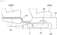
- the battery storage device for the electric vehicle includes a casing 20, an intake duct 30, and a discharge duct 40.
- the casing 20 is coupled to a lower portion of a vehicle floor 10 to accommodate a battery module 21 therein, and has an air inlet 22 (shown in FIG. 10 ) into which air for cooling the battery module is introduced, and an air outlet 23 (shown in FIG. 10 ) from which air used to cool the battery module 21 is discharged.
- the intake duct 30 is connected to an upper portion of the vehicle floor 10 to communicate with the air inlet 22, and extends indoors to guide indoor air into the casing 20.
- the discharge duct 40 is connected to communicate with the air outlet 23, and extends indoors or outdoors at a position spaced apart from the intake duct 30 to guide the air used to cool the battery module 21 and thereby discharge the air to an outside of the casing 20.
- the casing 20 may have the battery module 21 therein to supply power, and may be separated into upper and lower portions, which are assembled with each other.
- various electric components and a blowing device C for circulating the air are provided in the casing 20.
- the air inlet 22 into which the air is introduced to cool the battery module 21, and the air outlet 23 from which the air used to cool the battery module 21 is discharged are formed in the casing 20.
- the blowing device C may be installed around the air outlet 23, and may use the air circulated in the casing 20 to cool the battery module 21 in an air cooling manner.
- the intake duct 30 may be connected to communicate with the air inlet 22 of the casing 20, and may extend indoors so that the indoor air circulates in the casing 20.
- the intake duct 30 may circulate the outdoor air into the casing 20.
- a contamination level is high and an outdoor temperature is varied.
- the intake duct is formed to circulate indoor air, which is low in contamination level and maintains the temperature of an optimum level, into the casing 20.
- the discharge duct 40 is connected to the air outlet 23 of the casing 20 to communicate therewith.
- the discharge duct 40 extends indoors or outdoors at a position spaced apart from the intake duct 30, and guides the air used to cool the battery module 21 to discharge the air to the outside of the casing 20.
- the discharge duct 40 may extend outdoors to discharge the air used to cool the battery module 21 to the outside, or may extend indoors to control the internal temperature of the vehicle using the air that is increased in temperature as the battery module 21 is cooled.
- the present disclosure allows the battery module 21 to be cooled in the air cooling manner as the indoor air circulates in the casing 20, through the intake duct 30 and the discharge duct 40 installed in the casing 20.
- a plurality of seats S may be mounted on the vehicle floor 10
- the intake duct 30 may extend under a front seat S1 in the vehicle to suction the indoor air
- the discharge duct 40 may extend under or on a side of a rear seat S2 to discharge the air used to cool the battery module 21.
- the plurality of seats may be include the front seat S1 and the rear seat S2.
- the front seat S1 may correspond to a seat of a first row
- the rear seat S2 may correspond to a seat of a second row.
- the intake duct 30 is provided under the front seat S1 to suction the indoor air, the indoor air of a low contamination level may be suctioned and interference between a passenger and a structure may be avoided.
- the discharge duct 40 extends under or on a side of the rear seat S2 to discharge the air used to cool the battery module 21.
- the air discharged through the discharge duct 40 is not transmitted to a passenger, and does not interfere with another structure.
- the discharge duct 40 is configured such that the air used to cool the battery module 21 is discharged to the inside of the vehicle.
- the internal temperature of the vehicle may be controlled by the air that is increased in temperature as the battery module 21 is cooled.
- Such a discharge duct 40 may be configured such that the air used to cool the battery module 21 is discharged indoors or outdoors, thus controlling the internal temperature. That is, as shown in FIG. 3 , the discharge duct 40 may include a first discharge path 40a that communicates with the air outlet 23 and extends under or on a side of the rear seat S2 to discharge the air to the inside of the vehicle, and a second discharge path 40b that branches off from the first discharge path 40a and extends outdoors to discharge the air to the outside of the vehicle. A regulating valve 40c may be provided at a junction of the first discharge path 40a and the second discharge path 40b. The first discharge path 40a should be configured to discharge the air used to cool the battery module 21 to the inside of the vehicle. Thus, the first discharge path is preferably formed to extend under the rear seat S2.
- the regulating valve 40c may be controlled by a controller to selectively move the air used to cool the battery module 21 to the first discharge path 40a or the second discharge path 40b.
- the controller may collate information about the temperature of the air passing through the battery module 21 and the internal temperature using various sensors to control the regulating valve 40c.
- the air that is increased in temperature as the battery module 21 is cooled may be selectively supplied to the inside or the outside of the vehicle depending on the internal temperature, so that the energy efficiency can be improved by selectively using the air that is used to cool the battery module 21.
- the intake duct 30 may have an inlet port 31 into which the indoor air is introduced.
- the inlet port 31 may be located above the floor to be spaced apart therefrom.
- a mesh structure (not shown) may be applied to the inlet port 31 of the intake duct 30.
- the inlet port may be provided with a filter (not shown) to filter foreign matter.
- the intake duct 30 may include an edge portion 30a that is coupled to the vehicle floor 10, and a duct portion 30b that extends upwards from a center of the edge portion 30a.
- the inlet port 31 may be formed on an end of the duct portion 30b, so that the inlet port 31 may be located above the floor to be spaced therefrom.
- the edge portion 30a of the intake duct 30 may be fastened to the vehicle floor 10 by bolting, and the duct portion 30b may extend to be higher than the vehicle floor 10 in which the front seat S1 is installed.
- the intake duct 30 may include a cover portion 32 that is located above the inlet port 31 to be spaced apart therefrom and has an area sufficient to cover the inlet port 31.
- the cover portion 32 is spaced apart from the inlet port 31, the inflow of foreign matter can be blocked without interfering with the flow of the air into the inlet port 31.
- the inlet port 31 of the intake duct 30 is formed to be open upwards, it becomes difficult to introduce air when an obstacle occurs at an upper position.
- the cover portion 32 prevents the obstacle from closing the inlet port 31, air may be smoothly introduced through the intake duct 30.
- the intake duct 30 may be disposed adjacent to an air conditioning duct 50 that discharges conditioned air to the front seat S1, so that the intake duct 30 may suction the conditioned air.
- the air conditioning duct 50 may be configured to discharge heating or cooling air to the inside of the vehicle, and may be configured as a separate air conditioner to deliver air from the front seat S1 to the intake duct 30.
- the intake duct 30 may suction clean filtered air that is discharged through the air conditioning duct 50, and may be supplied with the cooling air through the air conditioning duct 50 in conjunction with the air conditioner, thus improving the cooling efficiency of the battery module 21.
- the intake duct 30 is disposed adjacent to the air conditioning duct 50.
- air optimized to control the temperature of the battery module 21 may be introduced into the intake duct 30, thus allowing the temperature of the battery module 21 to be efficiently controlled.
- the discharge duct 40 may have a discharge port 41 that is formed to discharge the air used to cool the battery module 21.
- the discharge port 41 may be formed under or on a side of the rear seat S2 to extend rearwards.
- the discharge duct 40 is formed such that a first end thereof is connected to communicate with the air outlet 23 of the casing 20 and a second end thereof extends under or on a side of the rear seat S2. At the second end, the discharge port 41 is formed rearwards. Since the discharge port 41 of the discharge duct 40 is formed rearwards, air discharged through the discharge port 41 is prevented from being transmitted to a passenger sitting on the rear seat S2. Furthermore, the air that is used to cool the battery module 21 and then is discharged through the discharge port 41 may be naturally discharged from a rear position in the vehicle to the outside thereof.
- the discharge duct 40 extends under the rear seat S2, space is provided on both sides of the rear seat S2, thus securing indoor space. If the discharge duct extends on a side of the rear seat S2, space is provided under the rear seat S2, so that it is advantageous for securing a foot insert space for a passenger sitting on a third row seat and designing a seat.
- a grill portion 42 having a plurality of holes may be provided in the discharge duct 40 to be installed in the discharge port 41.
- the holes may be formed by a plurality of ribs that cross the discharge port 41 vertically and horizontally.
- a mesh structure is formed as the grill portion 42 has the plurality of holes formed by the plurality of ribs. This may block foreign matter introduced into the discharge port 41 without interfering with the flow of the air discharged through the discharge port 41.
- the air circulated through the discharge duct 40 may be smoothly discharged through the discharge port 41, so that it is possible to stably maintain the cooling of the battery module 21.
- the discharge path 13 is formed in the vehicle floor 10 under or on a side of the rear seat S2 to communicate with an outdoor side.
- the discharge duct 40 extends to communicate with the discharge path 13, the air used to cool the battery module 21 and then discharged through the discharge port 41 may be discharged through the discharge path 13 to the outside.
- the discharge path 13 of the vehicle floor 10 is provided under a carpet of the floor to be located under or on a side of the rear seat S2, and extends to the outdoor side.
- the discharge port 41 communicates with the discharge path 13, so that the air used to cool the battery module 21 is discharged through the discharge path 13 to the outside.
- the air that is increased in temperature as the battery module 21 is cooled is discharged to the outside through the discharge path 13, so that the air does not affect indoor temperature and thereby the indoor temperature can be maintained.
- the plurality of seats is installed on the vehicle floor 10, and the casing 20 is installed under the vehicle floor 10.
- An inlet portion 11 and an outlet portion 12 may be formed on the vehicle body.
- the inlet portion 11 matches with the air inlet 22 of the casing 20 and is open vertically
- the outlet portion 12 matches with the air outlet 23 of the casing 20 and is open vertically.
- indoor space is provided above the vehicle floor 10 to accommodate the plurality of seats S, and external space is provided under the vehicle floor 10, and the casing 20 is installed in the vehicle floor 10, thus making it easy to secure the indoor space and improving maintenability.
- the intake duct 30 and the discharge duct 40 provided in the upper portion of the vehicle floor 10 are coupled to communicate with the inlet portion 11 and the outlet portion 12, respectively, thus allowing air to circulate in the casing 20. That is, according to the present disclosure, the battery module 21 in the casing 20 is cooled in the air cooling manner using the indoor air.
- the intake duct 30 and the discharge duct 40 installed in the upper portion of the vehicle floor 10 allow the indoor air to be circulated in the casing 20 installed under the vehicle floor 10, through the inlet portion 11 and the outlet portion 12 of the vehicle floor 10.
- the casing 20 may discharge the indoor air after the indoor air introduced through the intake duct 30 cools the battery module 21 and then cools the battery module 21 again through the discharge duct 40.
- a first watertight pad 14 may be provided in the upper portion of the vehicle floor 10 to enclose a circumstance of the inlet portion 11, and the intake duct 30 may be mounted so that the first watertight pad 14 is interposed between the intake duct and the inlet portion 11 of the vehicle floor 10, thus allowing a gap between the intake duct 30 and the vehicle floor 10 to be sealed by the first watertight pad 14.
- a second watertight pad 15 may be provided in the upper portion of the vehicle floor 10 to enclose a circumstance of the outlet portion 12, and the discharge duct 40 may be mounted so that the second watertight pad 15 is interposed between the discharge duct and the outlet portion 12 of the vehicle floor 10, thus allowing a gap between the discharge duct 40 and the vehicle floor 10 to be sealed by the second watertight pad 15.
- each of the first watertight pad 14 and the second watertight pad 15 may be made of an elastically deformable rubber material.
- the inlet portion 11 and the outlet portion 12 are sealed through the first watertight pad 14 and the second watertight pad 15, respectively.
- the intake duct 30 is mounted so that the first watertight pad 14 is interposed between the intake duct and the inlet portion 11 of the vehicle floor 10, the first watertight pad 14 comes into close contact with the intake duct 30 and the inlet portion 11, thus preventing foreign matter and water on the vehicle floor 10 from entering the inlet portion 11.
- the discharge duct 40 is mounted so that the second watertight pad 15 is interposed between the discharge duct and the outlet portion 12 of the vehicle floor 10, the second watertight pad 15 comes into close contact with the discharge duct 40 and the outlet portion 12, thus preventing foreign matter and water on the vehicle floor 10 from entering the outlet portion 12.
- the intake duct 30 and the discharge duct 40 are water-tightly mounted on the vehicle floor 10 through the first watertight pad 14 and the second watertight pad 15, thus preventing foreign matter and water from entering the inlet portion 11 and the outlet portion 12 of the vehicle floor 10 and thereby preventing the battery module 21 from being contaminated.
- a third watertight pad 16 is provided on the casing 20 to enclose a circumstance of the air inlet 22.
- a gap between the air inlet 22 of the casing 20 and the vehicle floor 10 may be sealed by a third watertight pad 16.
- a fourth watertight pad 17 is provided on the casing 20 to enclose a circumstance of the air outlet 23.
- a gap between the air outlet 23 of the casing 20 and the vehicle floor 10 may be sealed by the fourth watertight pad 17.
- each of the third watertight pad 16 and the fourth watertight pad 17 may be made of an elastically deformable rubber material.
- the air inlet 22 and the air outlet 23 of the casing 20 are sealed by the third watertight pad 16 and the fourth watertight pad 17, respectively.
- the third watertight pad 16 is interposed between the casing 20 and the vehicle floor 10 when the air inlet 22 is mounted on the inlet portion 11 of the vehicle floor 10 when the air inlet 22 is mounted on the inlet portion 11 of the vehicle floor 10
- a gap between the air inlet 22 of the casing 20 and the inlet portion 11 of the vehicle floor 10 is sealed, thus preventing foreign matter and water from being introduced.
- the fourth watertight pad 17 is interposed between the casing 20 and the vehicle floor 10 when the air outlet 23 of the casing 20 is mounted on the outlet portion 12 of the vehicle floor 10, a gap between the air outlet 23 of the casing 20 and the outlet portion 12 of the vehicle floor 10 is sealed, thus preventing foreign matter and water from being introduced.
- the casing 20 is water-tightly mounted on the lower portion of the vehicle floor 10 through the third watertight pad 16 and the fourth watertight pad 17, the penetration of the foreign matter and the water through the air inlet 22 and the air outlet 23 of the casing 20 is prevented, and consequently the contamination of the battery module 21 is prevented.
- a shock absorbing pad 70 may be provided on the extension portion 60 to absorb shock and vibration.
- the intake duct 30 extends under the front seat S1, and the discharge duct 40 extends under the rear seat S2.
- the discharge duct 40 extends under the rear seat S2.
- the discharge duct 40 has the extension portion 60 extending along the vehicle floor 10, thus defining a path in which the air used to cool the battery module 21 in the casing 20 is circulated.
- the shock absorbing pad 70 made of an elastic material to absorb noise and vibration is provided on the extension portion 60, inconvenience caused by noise and vibration is prevented from being transferred to a passenger.
- the shock absorbing pad 70 may be provided on each of inner and outer sides of the extension portion 60 to extend in a longitudinal direction. Hence, noise and vibration caused by the flow of air passing through the inner side of the extension portion 60 are absorbed by the shock absorbing pad 70, and shock acting on the outer side of the extension portion 60 is also absorbed by the shock absorbing pad 70, so that the durability of the extension portion 60 is ensured.
- the battery storage device for the electric vehicle is configured such that the battery casing 20 is provided under the vehicle floor 10, thus securing the indoor space, and the battery module 21 is cooled using the indoor air, thus simplifying the cooling structure and reducing the manufacturing cost.
Landscapes
- Engineering & Computer Science (AREA)
- Chemical & Material Sciences (AREA)
- Chemical Kinetics & Catalysis (AREA)
- General Chemical & Material Sciences (AREA)
- Electrochemistry (AREA)
- Manufacturing & Machinery (AREA)
- Mechanical Engineering (AREA)
- Transportation (AREA)
- Combustion & Propulsion (AREA)
- Physics & Mathematics (AREA)
- Thermal Sciences (AREA)
- Life Sciences & Earth Sciences (AREA)
- Sustainable Development (AREA)
- Sustainable Energy (AREA)
- Power Engineering (AREA)
- Arrangement Or Mounting Of Propulsion Units For Vehicles (AREA)
- Cooling, Air Intake And Gas Exhaust, And Fuel Tank Arrangements In Propulsion Units (AREA)
- Secondary Cells (AREA)
Abstract
Description
- The present disclosure relates to a battery storage device for an electric vehicle, in which a battery module is installed therein and a cooling device is provided to cool the battery module, and to an electric vehicle.
- Recently, due to environmental problems, such as high oil prices and the like, interest in environmentally friendly vehicles is increasing. Thus, various electric vehicles that are driven using electric energy are being developed.
- The electric vehicles are classified into a battery powered EV, a fuel cell EV that uses a fuel cell to power a motor, and a hybrid EV that uses both a motor and an engine.
- Particularly, the electric vehicle is provided with a battery module to store electric energy. The battery module accommodates a plurality of battery cell units in a battery casing. Since such a battery casing is large in volume and weight, it is important to secure a mounting space in a vehicle body so as to mount the battery casing on the vehicle body. In addition, as the battery module generates high-temperature heat during driving, it is required to cool the battery module. However, the conventional battery casing is not optimally designed considering the mounting space of the vehicle body and the cooling of the battery module.
- The description provided above as a related art of the present disclosure is only for helping understanding the background of the present disclosure and should not be construed as being included in the related art known by those skilled in the art.
- The present disclosure has been made in order to solve the above-mentioned problems in the prior art and an objective of the present disclosure is to provide a battery storage device for an electric vehicle, in which a battery casing is provided under a vehicle floor to secure an indoor space, and a battery module is cooled using indoor air, thus simplifying a cooling structure and reducing a manufacturing cost, and an electric vehicle.
- In order to achieve the object of the present disclosure, a battery storage device for an electric vehicle, including a casing to be coupled to a lower portion of a vehicle floor to accommodate a battery module therein, and including an air inlet into which air for cooling the battery module is introduced, and an air outlet from which air used to cool the battery module is discharged, an intake duct to be connected to an upper portion of the vehicle floor to communicate with the air inlet, and extending indoors to guide indoor air into the casing; and a discharge duct connected to communicate with the air outlet, and extending indoors or outdoors at a position spaced apart from the intake duct to guide the air used to cool the battery module and thereby discharge the air to an outside of the casing. Further, in order to achieve the object of the present disclosure, an electric vehicle comprises the above battery storage device.
- A plurality of seats may be provided on the vehicle floor, the intake duct may extend under a front seat to suction the indoor air, and the discharge duct may extend under or on a side of a rear seat to discharge the air used to cool the battery module.
- The intake duct may extend under the front seat to suction the indoor air, with an inlet port being formed in the intake duct to suction the indoor air, and the intake duct may extend under the front seat to be higher than the floor, so that the inlet port may be positioned above the floor to be spaced apart therefrom.
- The intake duct may include a cover portion that is located above the inlet port to be spaced apart therefrom and is formed to have an area sufficient to cover the inlet port, so that air may be introduced between the inlet port and the cover portion.
- The intake duct may be disposed adjacent to an air conditioning duct that discharges conditioned air to the front seat, so that the intake duct may suction the conditioned air.
- The discharge duct may extend under the rear seat to discharge the air used to cool the battery module, and may include a first discharge path communicates with the air outlet and extends under the rear seat to discharge the air to an inside of the vehicle, and a second discharge path that branches off from the first discharge path and extends outdoors to discharge the air to an outside of the vehicle, with a regulating valve provided on a junction of the first discharge path and the second discharge path.
- The discharge duct may include a discharge port that is formed to discharge the air used to cool the battery module, the discharge port being formed under or on the side of the rear seat to extend rearwards.
- The discharge path may be formed in the vehicle floor under or on the side of the rear seat to communicate with an outdoor side, and, as the discharge duct may extend to communicate with the discharge path, the air used to cool the battery module and discharged through the discharge port may be discharged through the discharge path to the outside.
- A grill portion having a plurality of holes may be provided in the discharge duct to be installed in the discharge port, the holes being formed by a plurality of ribs that cross the discharge port vertically and horizontally.
- The plurality of seats may be installed on the vehicle floor, the casing may be installed under the vehicle floor, and an inlet portion that matches with the air inlet of the casing and is open vertically, and an outlet portion that matches with the air outlet of the casing and is open vertically may be formed.
- A first watertight pad may be provided in the upper portion of the vehicle floor to enclose a circumstance of the inlet portion, and the intake duct may be mounted so that the first watertight pad is interposed between the intake duct and the inlet portion of the vehicle floor, thus allowing a gap between the intake duct and the vehicle floor to be sealed by the first watertight pad.
- A second watertight pad may be provided in the upper portion of the vehicle floor to enclose a circumstance of the outlet portion, and the discharge duct may be mounted so that the second watertight pad is interposed between the discharge duct and the outlet portion of the vehicle floor, thus allowing a gap between the discharge duct and the vehicle floor to be sealed by the second watertight pad.
- A third watertight pad may be provided on the casing to enclose a circumstance of the air inlet, so that a gap between the air inlet of the casing and the vehicle floor may be sealed by a third watertight pad when the casing is mounted in the lower portion of the vehicle floor.
- A fourth watertight pad may be provided on the casing to enclose a circumstance of the air outlet, so that a gap between the air outlet of the casing and the vehicle floor may be sealed by the fourth watertight pad, when the casing is mounted in the lower portion of the vehicle floor.
- The intake duct may extend to suction the indoor air under the front seat, and the discharge duct may extend to discharge the air used to cool the battery module under the rear seat, so that, when an extension portion is formed to extend along the vehicle floor, a shock absorbing pad may be provided on the extension portion to absorb shock and vibration.
- The shock absorbing pad may be provided on each of inner and outer sides of the extension portion to extend in a longitudinal direction.
- As described above, the battery storage device for the electric vehicle is configured such that the battery casing is provided under the vehicle floor to secure the indoor space, and the battery module is cooled using the indoor air, thus simplifying the cooling structure and reducing the manufacturing cost.
- The above and other objectives, features, and other advantages of the present disclosure will be more clearly understood from the following detailed description when taken in conjunction with the accompanying drawings, in which:
-
FIGS. 1 and2 are diagrams illustrating a battery storage device for an electric vehicle according to an embodiment of the present disclosure; and -
FIGS. 3 ,4 ,5 ,6 ,7 ,8 ,9 ,10 , and11 are diagrams illustrating the battery storage device for the electric vehicle ofFIG. 1 . - Hereinafter, a battery storage device for an electric vehicle according to an exemplary embodiment of the present disclosure will be described with reference to the accompanying drawings.
-
FIGS. 1 and2 are diagrams illustrating a battery storage device for an electric vehicle according to an embodiment of the present disclosure, andFIGS. 3 to 11 are diagrams illustrating the battery storage device for the electric vehicle ofFIG. 1 . - As shown in
FIGS. 1 and2 , the battery storage device for the electric vehicle according to the present disclosure includes acasing 20, anintake duct 30, and adischarge duct 40. Thecasing 20 is coupled to a lower portion of avehicle floor 10 to accommodate abattery module 21 therein, and has an air inlet 22 (shown inFIG. 10 ) into which air for cooling the battery module is introduced, and an air outlet 23 (shown inFIG. 10 ) from which air used to cool thebattery module 21 is discharged. Theintake duct 30 is connected to an upper portion of thevehicle floor 10 to communicate with theair inlet 22, and extends indoors to guide indoor air into thecasing 20. Thedischarge duct 40 is connected to communicate with theair outlet 23, and extends indoors or outdoors at a position spaced apart from theintake duct 30 to guide the air used to cool thebattery module 21 and thereby discharge the air to an outside of thecasing 20. - The
casing 20 may have thebattery module 21 therein to supply power, and may be separated into upper and lower portions, which are assembled with each other. In addition to thebattery module 21, various electric components and a blowing device C for circulating the air are provided in thecasing 20. Theair inlet 22 into which the air is introduced to cool thebattery module 21, and theair outlet 23 from which the air used to cool thebattery module 21 is discharged are formed in thecasing 20. Thus, when the blowing device C is driven, the air introduced through theair inlet 22 cools thebattery module 21, and then is discharged to theair outlet 23. In this regard, the blowing device C may be installed around theair outlet 23, and may use the air circulated in thecasing 20 to cool thebattery module 21 in an air cooling manner. - Meanwhile, the
intake duct 30 may be connected to communicate with theair inlet 22 of thecasing 20, and may extend indoors so that the indoor air circulates in thecasing 20. Of course, theintake duct 30 may circulate the outdoor air into thecasing 20. In the case of the outdoor air, a contamination level is high and an outdoor temperature is varied. The intake duct is formed to circulate indoor air, which is low in contamination level and maintains the temperature of an optimum level, into thecasing 20. - The
discharge duct 40 is connected to theair outlet 23 of thecasing 20 to communicate therewith. Thedischarge duct 40 extends indoors or outdoors at a position spaced apart from theintake duct 30, and guides the air used to cool thebattery module 21 to discharge the air to the outside of thecasing 20. Here, thedischarge duct 40 may extend outdoors to discharge the air used to cool thebattery module 21 to the outside, or may extend indoors to control the internal temperature of the vehicle using the air that is increased in temperature as thebattery module 21 is cooled. - As such, the present disclosure allows the
battery module 21 to be cooled in the air cooling manner as the indoor air circulates in thecasing 20, through theintake duct 30 and thedischarge duct 40 installed in thecasing 20. - The above-described component of the present disclosure will be described in detail. As shown in
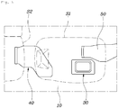
FIG. 1 , a plurality of seats S may be mounted on thevehicle floor 10, theintake duct 30 may extend under a front seat S1 in the vehicle to suction the indoor air, and thedischarge duct 40 may extend under or on a side of a rear seat S2 to discharge the air used to cool thebattery module 21. - Here, the plurality of seats may be include the front seat S1 and the rear seat S2. The front seat S1 may correspond to a seat of a first row, and the rear seat S2 may correspond to a seat of a second row.
- Particularly, since the
intake duct 30 is provided under the front seat S1 to suction the indoor air, the indoor air of a low contamination level may be suctioned and interference between a passenger and a structure may be avoided. - The
discharge duct 40 extends under or on a side of the rear seat S2 to discharge the air used to cool thebattery module 21. Thus, the air discharged through thedischarge duct 40 is not transmitted to a passenger, and does not interfere with another structure. Furthermore, thedischarge duct 40 is configured such that the air used to cool thebattery module 21 is discharged to the inside of the vehicle. Thus, the internal temperature of the vehicle may be controlled by the air that is increased in temperature as thebattery module 21 is cooled. - Such a
discharge duct 40 may be configured such that the air used to cool thebattery module 21 is discharged indoors or outdoors, thus controlling the internal temperature. That is, as shown inFIG. 3 , thedischarge duct 40 may include afirst discharge path 40a that communicates with theair outlet 23 and extends under or on a side of the rear seat S2 to discharge the air to the inside of the vehicle, and asecond discharge path 40b that branches off from thefirst discharge path 40a and extends outdoors to discharge the air to the outside of the vehicle. A regulatingvalve 40c may be provided at a junction of thefirst discharge path 40a and thesecond discharge path 40b. Thefirst discharge path 40a should be configured to discharge the air used to cool thebattery module 21 to the inside of the vehicle. Thus, the first discharge path is preferably formed to extend under the rear seat S2. - The regulating
valve 40c may be controlled by a controller to selectively move the air used to cool thebattery module 21 to thefirst discharge path 40a or thesecond discharge path 40b. The controller may collate information about the temperature of the air passing through thebattery module 21 and the internal temperature using various sensors to control the regulatingvalve 40c. Thus, the air that is increased in temperature as thebattery module 21 is cooled may be selectively supplied to the inside or the outside of the vehicle depending on the internal temperature, so that the energy efficiency can be improved by selectively using the air that is used to cool thebattery module 21. - Meanwhile, as shown in
FIG. 4 , theintake duct 30 may have aninlet port 31 into which the indoor air is introduced. As theintake duct 30 extends under the front seat S1 to be higher than a floor, theinlet port 31 may be located above the floor to be spaced apart therefrom. A mesh structure (not shown) may be applied to theinlet port 31 of theintake duct 30. The inlet port may be provided with a filter (not shown) to filter foreign matter. - In other words, the
intake duct 30 may include anedge portion 30a that is coupled to thevehicle floor 10, and aduct portion 30b that extends upwards from a center of theedge portion 30a. Theinlet port 31 may be formed on an end of theduct portion 30b, so that theinlet port 31 may be located above the floor to be spaced therefrom. Here, theedge portion 30a of theintake duct 30 may be fastened to thevehicle floor 10 by bolting, and theduct portion 30b may extend to be higher than thevehicle floor 10 in which the front seat S1 is installed. - As such, as the
inlet port 31 of theintake duct 30 is spaced apart from the floor, foreign matter and water of the floor are prevented from being introduced into theinlet port 31. - Furthermore, the
intake duct 30 may include acover portion 32 that is located above theinlet port 31 to be spaced apart therefrom and has an area sufficient to cover theinlet port 31. In this way, since thecover portion 32 is spaced apart from theinlet port 31, the inflow of foreign matter can be blocked without interfering with the flow of the air into theinlet port 31. Particularly, as theinlet port 31 of theintake duct 30 is formed to be open upwards, it becomes difficult to introduce air when an obstacle occurs at an upper position. As thecover portion 32 prevents the obstacle from closing theinlet port 31, air may be smoothly introduced through theintake duct 30. - Meanwhile, as shown in
FIG. 5 , theintake duct 30 may be disposed adjacent to anair conditioning duct 50 that discharges conditioned air to the front seat S1, so that theintake duct 30 may suction the conditioned air. Here, theair conditioning duct 50 may be configured to discharge heating or cooling air to the inside of the vehicle, and may be configured as a separate air conditioner to deliver air from the front seat S1 to theintake duct 30. - Hence, the
intake duct 30 may suction clean filtered air that is discharged through theair conditioning duct 50, and may be supplied with the cooling air through theair conditioning duct 50 in conjunction with the air conditioner, thus improving the cooling efficiency of thebattery module 21. As such, theintake duct 30 is disposed adjacent to theair conditioning duct 50. Thus, as the conditioned air that is controlled in temperature by the air conditioner is supplied to theintake duct 30, air optimized to control the temperature of thebattery module 21 may be introduced into theintake duct 30, thus allowing the temperature of thebattery module 21 to be efficiently controlled. - Meanwhile, as shown in
FIGS. 5-7 , thedischarge duct 40 may have adischarge port 41 that is formed to discharge the air used to cool thebattery module 21. Thedischarge port 41 may be formed under or on a side of the rear seat S2 to extend rearwards. - In other words, the
discharge duct 40 is formed such that a first end thereof is connected to communicate with theair outlet 23 of thecasing 20 and a second end thereof extends under or on a side of the rear seat S2. At the second end, thedischarge port 41 is formed rearwards. Since thedischarge port 41 of thedischarge duct 40 is formed rearwards, air discharged through thedischarge port 41 is prevented from being transmitted to a passenger sitting on the rear seat S2. Furthermore, the air that is used to cool thebattery module 21 and then is discharged through thedischarge port 41 may be naturally discharged from a rear position in the vehicle to the outside thereof. Here, if thedischarge duct 40 extends under the rear seat S2, space is provided on both sides of the rear seat S2, thus securing indoor space. If the discharge duct extends on a side of the rear seat S2, space is provided under the rear seat S2, so that it is advantageous for securing a foot insert space for a passenger sitting on a third row seat and designing a seat. - Furthermore, a
grill portion 42 having a plurality of holes may be provided in thedischarge duct 40 to be installed in thedischarge port 41. The holes may be formed by a plurality of ribs that cross thedischarge port 41 vertically and horizontally. As such, as thegrill portion 42 has the plurality of holes formed by the plurality of ribs, a mesh structure is formed. This may block foreign matter introduced into thedischarge port 41 without interfering with the flow of the air discharged through thedischarge port 41. Thus, the air circulated through thedischarge duct 40 may be smoothly discharged through thedischarge port 41, so that it is possible to stably maintain the cooling of thebattery module 21. - Meanwhile, as seen from
FIG. 1 , thedischarge path 13 is formed in thevehicle floor 10 under or on a side of the rear seat S2 to communicate with an outdoor side. As thedischarge duct 40 extends to communicate with thedischarge path 13, the air used to cool thebattery module 21 and then discharged through thedischarge port 41 may be discharged through thedischarge path 13 to the outside. - Here, the
discharge path 13 of thevehicle floor 10 is provided under a carpet of the floor to be located under or on a side of the rear seat S2, and extends to the outdoor side. In thedischarge duct 40 extending to communicating with thedischarge path 13, thedischarge port 41 communicates with thedischarge path 13, so that the air used to cool thebattery module 21 is discharged through thedischarge path 13 to the outside. The air that is increased in temperature as thebattery module 21 is cooled is discharged to the outside through thedischarge path 13, so that the air does not affect indoor temperature and thereby the indoor temperature can be maintained. - Meanwhile, as shown in
FIGS. 1 and9 , the plurality of seats is installed on thevehicle floor 10, and thecasing 20 is installed under thevehicle floor 10. Aninlet portion 11 and anoutlet portion 12 may be formed on the vehicle body. Here, theinlet portion 11 matches with theair inlet 22 of thecasing 20 and is open vertically, and theoutlet portion 12 matches with theair outlet 23 of thecasing 20 and is open vertically. - In other words, indoor space is provided above the
vehicle floor 10 to accommodate the plurality of seats S, and external space is provided under thevehicle floor 10, and thecasing 20 is installed in thevehicle floor 10, thus making it easy to secure the indoor space and improving maintenability. - Since the
inlet portion 11 matching with theair inlet 22 of thecasing 20 and theoutlet portion 12 matching with theair outlet 23 of thecasing 20 are formed in thevehicle floor 10, theintake duct 30 and thedischarge duct 40 provided in the upper portion of thevehicle floor 10 are coupled to communicate with theinlet portion 11 and theoutlet portion 12, respectively, thus allowing air to circulate in thecasing 20. That is, according to the present disclosure, thebattery module 21 in thecasing 20 is cooled in the air cooling manner using the indoor air. Theintake duct 30 and thedischarge duct 40 installed in the upper portion of thevehicle floor 10 allow the indoor air to be circulated in thecasing 20 installed under thevehicle floor 10, through theinlet portion 11 and theoutlet portion 12 of thevehicle floor 10. Thus, thecasing 20 may discharge the indoor air after the indoor air introduced through theintake duct 30 cools thebattery module 21 and then cools thebattery module 21 again through thedischarge duct 40. - Meanwhile, as shown in
FIG. 9 , a firstwatertight pad 14 may be provided in the upper portion of thevehicle floor 10 to enclose a circumstance of theinlet portion 11, and theintake duct 30 may be mounted so that the firstwatertight pad 14 is interposed between the intake duct and theinlet portion 11 of thevehicle floor 10, thus allowing a gap between theintake duct 30 and thevehicle floor 10 to be sealed by the firstwatertight pad 14. Furthermore, a secondwatertight pad 15 may be provided in the upper portion of thevehicle floor 10 to enclose a circumstance of theoutlet portion 12, and thedischarge duct 40 may be mounted so that the secondwatertight pad 15 is interposed between the discharge duct and theoutlet portion 12 of thevehicle floor 10, thus allowing a gap between thedischarge duct 40 and thevehicle floor 10 to be sealed by the secondwatertight pad 15. - Here, each of the first
watertight pad 14 and the secondwatertight pad 15 may be made of an elastically deformable rubber material. Theinlet portion 11 and theoutlet portion 12 are sealed through the firstwatertight pad 14 and the secondwatertight pad 15, respectively. - That is, as the
intake duct 30 is mounted so that the firstwatertight pad 14 is interposed between the intake duct and theinlet portion 11 of thevehicle floor 10, the firstwatertight pad 14 comes into close contact with theintake duct 30 and theinlet portion 11, thus preventing foreign matter and water on thevehicle floor 10 from entering theinlet portion 11. Furthermore, as thedischarge duct 40 is mounted so that the secondwatertight pad 15 is interposed between the discharge duct and theoutlet portion 12 of thevehicle floor 10, the secondwatertight pad 15 comes into close contact with thedischarge duct 40 and theoutlet portion 12, thus preventing foreign matter and water on thevehicle floor 10 from entering theoutlet portion 12. - Thus, the
intake duct 30 and thedischarge duct 40 are water-tightly mounted on thevehicle floor 10 through the firstwatertight pad 14 and the secondwatertight pad 15, thus preventing foreign matter and water from entering theinlet portion 11 and theoutlet portion 12 of thevehicle floor 10 and thereby preventing thebattery module 21 from being contaminated. - Meanwhile, as shown in
FIG. 10 , a thirdwatertight pad 16 is provided on thecasing 20 to enclose a circumstance of theair inlet 22. When thecasing 20 is mounted in the lower portion of thevehicle floor 10, a gap between theair inlet 22 of thecasing 20 and thevehicle floor 10 may be sealed by a thirdwatertight pad 16. - Furthermore, a fourth
watertight pad 17 is provided on thecasing 20 to enclose a circumstance of theair outlet 23. When thecasing 20 is mounted in the lower portion of thevehicle floor 10, a gap between theair outlet 23 of thecasing 20 and thevehicle floor 10 may be sealed by the fourthwatertight pad 17. - Here, each of the third
watertight pad 16 and the fourthwatertight pad 17 may be made of an elastically deformable rubber material. Theair inlet 22 and theair outlet 23 of thecasing 20 are sealed by the thirdwatertight pad 16 and the fourthwatertight pad 17, respectively. - As the
casing 20 is mounted on the lower portion of thevehicle floor 10, foreign matter and water generated during driving should be prevented from being introduced into theair inlet 22 or theair outlet 23 of thecasing 20. - To this end, as the third
watertight pad 16 is interposed between thecasing 20 and thevehicle floor 10 when theair inlet 22 is mounted on theinlet portion 11 of thevehicle floor 10, a gap between theair inlet 22 of thecasing 20 and theinlet portion 11 of thevehicle floor 10 is sealed, thus preventing foreign matter and water from being introduced. Furthermore, as the fourthwatertight pad 17 is interposed between thecasing 20 and thevehicle floor 10 when theair outlet 23 of thecasing 20 is mounted on theoutlet portion 12 of thevehicle floor 10, a gap between theair outlet 23 of thecasing 20 and theoutlet portion 12 of thevehicle floor 10 is sealed, thus preventing foreign matter and water from being introduced. - Since the
casing 20 is water-tightly mounted on the lower portion of thevehicle floor 10 through the thirdwatertight pad 16 and the fourthwatertight pad 17, the penetration of the foreign matter and the water through theair inlet 22 and theair outlet 23 of thecasing 20 is prevented, and consequently the contamination of thebattery module 21 is prevented. - Meanwhile, the
intake duct 30 extends to suction the indoor air under the front seat S1, and thedischarge duct 40 extends to discharge the air used to cool thebattery module 21 under the rear seat S2. Thus, in the case of forming anextension portion 60 along thevehicle floor 10, ashock absorbing pad 70 may be provided on theextension portion 60 to absorb shock and vibration. - According to the present disclosure, the
intake duct 30 extends under the front seat S1, and thedischarge duct 40 extends under the rear seat S2. In the present disclosure, as thecasing 20 is disposed on the front side of thevehicle floor 10, thedischarge duct 40 extends under the rear seat S2. As seen fromFIG. 7 , thedischarge duct 40 has theextension portion 60 extending along thevehicle floor 10, thus defining a path in which the air used to cool thebattery module 21 in thecasing 20 is circulated. However, since theextension portion 60 of thedischarge duct 40 extends along thevehicle floor 10, vibration and noise may be generated when the air used to cool thebattery module 21 is discharged. Therefore, since theshock absorbing pad 70 made of an elastic material to absorb noise and vibration is provided on theextension portion 60, inconvenience caused by noise and vibration is prevented from being transferred to a passenger. - As shown in
FIG. 11 , theshock absorbing pad 70 may be provided on each of inner and outer sides of theextension portion 60 to extend in a longitudinal direction. Hence, noise and vibration caused by the flow of air passing through the inner side of theextension portion 60 are absorbed by theshock absorbing pad 70, and shock acting on the outer side of theextension portion 60 is also absorbed by theshock absorbing pad 70, so that the durability of theextension portion 60 is ensured. - As described above, the battery storage device for the electric vehicle is configured such that the
battery casing 20 is provided under thevehicle floor 10, thus securing the indoor space, and thebattery module 21 is cooled using the indoor air, thus simplifying the cooling structure and reducing the manufacturing cost. - Although the present disclosure was described with reference to specific embodiments shown in the drawings, it is apparent to those skilled in the art that the present disclosure may be changed and modified in various ways without departing from the scope of the present disclosure, which is described in the following claims.
Claims (15)
- A battery storage device for an electric vehicle, comprising:a casing to be coupled to a lower portion of a vehicle floor to accommodate a battery module therein, the casing including an air inlet into which air for cooling the battery module is introduced, and an air outlet from which air used to cool the battery module is discharged;an intake duct to be connected to an upper portion of the vehicle floor to communicate with the air inlet, the intake duct extending indoors to guide indoor air into the casing; anda discharge duct connected to communicate with the air outlet, the discharge duct extending indoors or outdoors at a position spaced apart from the intake duct to guide the air used to cool the battery module and thereby discharge the air to an outside of the casing.
- An electric vehicle comprising the battery storage device of claim 1.
- The electric vehicle of claim 2,
wherein a plurality of seats is provided on the vehicle floor;
wherein the intake duct extends under a front seat to suction the indoor air; and
wherein the discharge duct extends under or on a side of a rear seat to discharge the air used to cool the battery module. - The electric vehicle of claim 2, wherein the intake duct extends under the front seat to suction the indoor air, with an inlet port being formed in the intake duct to suction the indoor air, and the intake duct extends under the front seat to be higher than the floor, so that the inlet port is positioned above the floor to be spaced apart therefrom.
- The electric vehicle of any one of claims 2 to 4, wherein the intake duct comprises a cover portion that is located above the inlet port to be spaced apart therefrom and is formed to have an area sufficient to cover the inlet port, so that air is introduced between the inlet port and the cover portion.
- The electric vehicle of any one of claims 2 to 5, wherein the intake duct is disposed adjacent to an air conditioning duct that discharges conditioned air to the front seat, so that the intake duct suctions the conditioned air.
- The electric vehicle of any one of claims 2 to 6, wherein the discharge duct extends under the rear seat to discharge the air used to cool the battery module, and comprises a first discharge path that communicates with the air outlet and extends under the rear seat to discharge the air to an inside of the vehicle, and a second discharge path that branches off from the first discharge path and extends outdoors to discharge the air to an outside of the vehicle, with a regulating valve provided on a junction of the first discharge path and the second discharge path.
- The electric vehicle of any one of claims 2 to 7, wherein the discharge duct comprises a discharge port that is configured to discharge the air used to cool the battery module, the discharge port being formed under or on the side of the rear seat to extend rearwards.
- The electric vehicle of claim 8,
wherein the discharge path is formed in the vehicle floor under or on the side of the rear seat to communicate with an outdoor side, and
wherein, as the discharge duct extends to communicate with the discharge path, the air used to cool the battery module and discharged through the discharge port is discharged through the discharge path to the outside. - The electric vehicle of claim 8 or 9, wherein a grill portion having a plurality of holes is provided in the discharge duct to be installed in the discharge port, the holes being formed by a plurality of ribs that cross the discharge port vertically and horizontally.
- The electric vehicle of any one of claims 2 to 10, wherein the plurality of seats is installed on the vehicle floor, the casing is installed under the vehicle floor, and an inlet portion that matches with the air inlet of the casing and is open vertically, and an outlet portion that matches with the air outlet of the casing and is open vertically are formed.
- The electric vehicle of any one of claims 2 to 11,
wherein a first watertight pad is provided in the upper portion of the vehicle floor to enclose a circumstance of the inlet portion; and
wherein the intake duct is mounted so that the first watertight pad is interposed between the intake duct and the inlet portion of the vehicle floor, allowing a gap between the intake duct and the vehicle floor to be sealed by the first watertight pad. - The electric vehicle of any one of claims 2 to 12,
wherein a second watertight pad is provided in the upper portion of the vehicle floor to enclose a circumstance of the outlet portion; and
wherein the discharge duct is mounted so that the second watertight pad is interposed between the discharge duct and the outlet portion of the vehicle floor, allowing a gap between the discharge duct and the vehicle floor to be sealed by the second watertight pad. - The electric vehicle of any one of claims 2 to 13, wherein a third watertight pad is provided on the casing to enclose a circumstance of the air inlet, so that a gap between the air inlet of the casing and the vehicle floor is sealed by a third watertight pad when the casing is mounted in the lower portion of the vehicle floor, and wherein preferably a fourth watertight pad is provided on the casing to enclose a circumstance of the air outlet, so that a gap between the air outlet of the casing and the vehicle floor is sealed by the fourth watertight pad when the casing is mounted in the lower portion of the vehicle floor.
- The electric vehicle of any one of claims 2 to 14, wherein the intake duct extends to suction the indoor air under the front seat, and the discharge duct extends to discharge the air used to cool the battery module under the rear seat, so that, when an extension portion is formed to extend along the vehicle floor, a shock absorbing pad is provided on the extension portion to absorb shock and vibration.
Applications Claiming Priority (1)
| Application Number | Priority Date | Filing Date | Title |
|---|---|---|---|
| KR1020200017839A KR20210104188A (en) | 2020-02-13 | 2020-02-13 | Battery storage device for electric vehicle |
Publications (2)
| Publication Number | Publication Date |
|---|---|
| EP3865327A1 true EP3865327A1 (en) | 2021-08-18 |
| EP3865327B1 EP3865327B1 (en) | 2022-12-14 |
Family
ID=72039405
Family Applications (1)
| Application Number | Title | Priority Date | Filing Date |
|---|---|---|---|
| EP20190251.7A Active EP3865327B1 (en) | 2020-02-13 | 2020-08-10 | Battery storage device for electric vehicle and electric vehicle |
Country Status (4)
| Country | Link |
|---|---|
| US (1) | US20210257694A1 (en) |
| EP (1) | EP3865327B1 (en) |
| KR (1) | KR20210104188A (en) |
| CN (1) | CN113320371A (en) |
Families Citing this family (5)
| Publication number | Priority date | Publication date | Assignee | Title |
|---|---|---|---|---|
| KR20220040168A (en) * | 2020-09-23 | 2022-03-30 | 현대자동차주식회사 | Battery case mounting structure for electric vehicle |
| JP7223801B2 (en) * | 2021-03-30 | 2023-02-16 | 本田技研工業株式会社 | electric vehicle |
| KR20230100288A (en) * | 2021-12-28 | 2023-07-05 | 현대자동차주식회사 | Electric mobility |
| KR102695411B1 (en) * | 2023-11-28 | 2024-08-16 | 국립공주대학교 산학협력단 | Cooling water supply valve to the lower battery casing |
| KR102689464B1 (en) * | 2023-11-28 | 2024-07-30 | 국립공주대학교 산학협력단 | Cooling water supply valve and pump to the lower battery casing |
Citations (4)
| Publication number | Priority date | Publication date | Assignee | Title |
|---|---|---|---|---|
| JP2008141945A (en) * | 2006-11-08 | 2008-06-19 | Toyota Motor Corp | Cooling device for electricity storage mechanism |
| FR2949096A3 (en) * | 2009-08-14 | 2011-02-18 | Renault Sa | Power battery cooling device for car, has reheating unit i.e. air-to-air heat exchanger, receiving reheated air from power battery and reheating conditioning air of air conditioning device to be transported towards passenger compartment |
| US20120138260A1 (en) * | 2010-12-03 | 2012-06-07 | Kia Motors Corporation | High voltage battery cooling system for a vehicle |
| US8297387B2 (en) * | 2007-09-28 | 2012-10-30 | Mitsubishi Jidosha Kabushiki Kaisha | Electric vehicle |
Family Cites Families (7)
| Publication number | Priority date | Publication date | Assignee | Title |
|---|---|---|---|---|
| US8006626B2 (en) * | 2007-05-07 | 2011-08-30 | General Electric Company | System and method for cooling a battery |
| KR101820784B1 (en) | 2011-02-17 | 2018-01-22 | 한온시스템 주식회사 | Battery cooling device for vehicle |
| KR101428175B1 (en) * | 2012-07-18 | 2014-08-08 | 현대자동차주식회사 | Battery cooling ducts |
| SE538916C2 (en) * | 2014-01-15 | 2017-02-14 | Scania Cv Ab | Procedure and system for adjusting the performance of a vehicle |
| DE102014221684A1 (en) * | 2014-07-11 | 2016-01-14 | Robert Bosch Gmbh | Housing for receiving a plurality of battery cells with a cooling device integrated in the housing |
| US10399455B2 (en) * | 2015-03-06 | 2019-09-03 | Honda Motor Co., Ltd. | Vehicle high-voltage system equipment unit, vehicle battery unit and vehicle |
| CN108807725B (en) * | 2017-05-03 | 2021-11-30 | 苏州科瓴精密机械科技有限公司 | Battery pack and electric starting gasoline engine with same |
-
2020
- 2020-02-13 KR KR1020200017839A patent/KR20210104188A/en active Search and Examination
- 2020-08-03 US US16/983,208 patent/US20210257694A1/en active Pending
- 2020-08-10 EP EP20190251.7A patent/EP3865327B1/en active Active
- 2020-09-17 CN CN202010978044.7A patent/CN113320371A/en active Pending
Patent Citations (4)
| Publication number | Priority date | Publication date | Assignee | Title |
|---|---|---|---|---|
| JP2008141945A (en) * | 2006-11-08 | 2008-06-19 | Toyota Motor Corp | Cooling device for electricity storage mechanism |
| US8297387B2 (en) * | 2007-09-28 | 2012-10-30 | Mitsubishi Jidosha Kabushiki Kaisha | Electric vehicle |
| FR2949096A3 (en) * | 2009-08-14 | 2011-02-18 | Renault Sa | Power battery cooling device for car, has reheating unit i.e. air-to-air heat exchanger, receiving reheated air from power battery and reheating conditioning air of air conditioning device to be transported towards passenger compartment |
| US20120138260A1 (en) * | 2010-12-03 | 2012-06-07 | Kia Motors Corporation | High voltage battery cooling system for a vehicle |
Also Published As
| Publication number | Publication date |
|---|---|
| US20210257694A1 (en) | 2021-08-19 |
| EP3865327B1 (en) | 2022-12-14 |
| CN113320371A (en) | 2021-08-31 |
| KR20210104188A (en) | 2021-08-25 |
Similar Documents
| Publication | Publication Date | Title |
|---|---|---|
| EP3865327A1 (en) | Battery storage device for electric vehicle and electric vehicle | |
| US7240752B2 (en) | Vehicular electrical equipment unit heating and cooling system and hybrid vehicle | |
| CN101687460B (en) | Cooling structure of battery | |
| KR101180954B1 (en) | High voltage battery cooling system of vehicle | |
| CN107791813B (en) | Housing structure of power equipment unit | |
| JP5630574B2 (en) | Heat exchange structure for vehicles | |
| KR20220040168A (en) | Battery case mounting structure for electric vehicle | |
| KR102269252B1 (en) | Battery assembly for electric vehicle | |
| US20150096816A1 (en) | Battery cooling apparatus | |
| CN109203976A (en) | Active vehicle base fabric for vehicle is set | |
| US11498404B2 (en) | Battery storage device for electric vehicle | |
| JP5831343B2 (en) | Mounting structure of an inverter for external power feeding of a vehicle equipped with a power supply device | |
| US8034473B2 (en) | Storage battery air-cooling device | |
| CN112109590A (en) | Cooling mechanism for vehicle | |
| JP2006216504A (en) | Heat insulating structure of battery pack | |
| US20240136548A1 (en) | Vehicle front structure | |
| CN220349799U (en) | Vehicle front end structure and vehicle | |
| US11437887B2 (en) | Ventilation for electric generator system | |
| JP2008260405A (en) | Battery cooling structure | |
| US20230173878A1 (en) | Air conditioner system for electric motor mobility | |
| KR100892524B1 (en) | Suction part for cooling of battery and high voltage accessories in unity package | |
| KR20230087849A (en) | Battery cooling system of hybrid vehicle | |
| KR20230012844A (en) | Golf cart | |
| JPS60174316A (en) | Ventilator for car | |
| CN118712563A (en) | Battery pack |
Legal Events
| Date | Code | Title | Description |
|---|---|---|---|
| PUAI | Public reference made under article 153(3) epc to a published international application that has entered the european phase |
Free format text: ORIGINAL CODE: 0009012 |
|
| STAA | Information on the status of an ep patent application or granted ep patent |
Free format text: STATUS: THE APPLICATION HAS BEEN PUBLISHED |
|
| AK | Designated contracting states |
Kind code of ref document: A1 Designated state(s): AL AT BE BG CH CY CZ DE DK EE ES FI FR GB GR HR HU IE IS IT LI LT LU LV MC MK MT NL NO PL PT RO RS SE SI SK SM TR |
|
| STAA | Information on the status of an ep patent application or granted ep patent |
Free format text: STATUS: REQUEST FOR EXAMINATION WAS MADE |
|
| 17P | Request for examination filed |
Effective date: 20220126 |
|
| RBV | Designated contracting states (corrected) |
Designated state(s): AL AT BE BG CH CY CZ DE DK EE ES FI FR GB GR HR HU IE IS IT LI LT LU LV MC MK MT NL NO PL PT RO RS SE SI SK SM TR |
|
| GRAP | Despatch of communication of intention to grant a patent |
Free format text: ORIGINAL CODE: EPIDOSNIGR1 |
|
| STAA | Information on the status of an ep patent application or granted ep patent |
Free format text: STATUS: GRANT OF PATENT IS INTENDED |
|
| INTG | Intention to grant announced |
Effective date: 20220713 |
|
| GRAS | Grant fee paid |
Free format text: ORIGINAL CODE: EPIDOSNIGR3 |
|
| GRAA | (expected) grant |
Free format text: ORIGINAL CODE: 0009210 |
|
| STAA | Information on the status of an ep patent application or granted ep patent |
Free format text: STATUS: THE PATENT HAS BEEN GRANTED |
|
| AK | Designated contracting states |
Kind code of ref document: B1 Designated state(s): AL AT BE BG CH CY CZ DE DK EE ES FI FR GB GR HR HU IE IS IT LI LT LU LV MC MK MT NL NO PL PT RO RS SE SI SK SM TR |
|
| REG | Reference to a national code |
Ref country code: GB Ref legal event code: FG4D |
|
| REG | Reference to a national code |
Ref country code: CH Ref legal event code: EP |
|
| REG | Reference to a national code |
Ref country code: DE Ref legal event code: R096 Ref document number: 602020006893 Country of ref document: DE |
|
| REG | Reference to a national code |
Ref country code: IE Ref legal event code: FG4D |
|
| REG | Reference to a national code |
Ref country code: AT Ref legal event code: REF Ref document number: 1537471 Country of ref document: AT Kind code of ref document: T Effective date: 20230115 |
|
| REG | Reference to a national code |
Ref country code: LT Ref legal event code: MG9D |
|
| REG | Reference to a national code |
Ref country code: NL Ref legal event code: MP Effective date: 20221214 |
|
| PG25 | Lapsed in a contracting state [announced via postgrant information from national office to epo] |
Ref country code: SE Free format text: LAPSE BECAUSE OF FAILURE TO SUBMIT A TRANSLATION OF THE DESCRIPTION OR TO PAY THE FEE WITHIN THE PRESCRIBED TIME-LIMIT Effective date: 20221214 Ref country code: NO Free format text: LAPSE BECAUSE OF FAILURE TO SUBMIT A TRANSLATION OF THE DESCRIPTION OR TO PAY THE FEE WITHIN THE PRESCRIBED TIME-LIMIT Effective date: 20230314 Ref country code: LT Free format text: LAPSE BECAUSE OF FAILURE TO SUBMIT A TRANSLATION OF THE DESCRIPTION OR TO PAY THE FEE WITHIN THE PRESCRIBED TIME-LIMIT Effective date: 20221214 Ref country code: FI Free format text: LAPSE BECAUSE OF FAILURE TO SUBMIT A TRANSLATION OF THE DESCRIPTION OR TO PAY THE FEE WITHIN THE PRESCRIBED TIME-LIMIT Effective date: 20221214 |
|
| REG | Reference to a national code |
Ref country code: AT Ref legal event code: MK05 Ref document number: 1537471 Country of ref document: AT Kind code of ref document: T Effective date: 20221214 |
|
| PG25 | Lapsed in a contracting state [announced via postgrant information from national office to epo] |
Ref country code: RS Free format text: LAPSE BECAUSE OF FAILURE TO SUBMIT A TRANSLATION OF THE DESCRIPTION OR TO PAY THE FEE WITHIN THE PRESCRIBED TIME-LIMIT Effective date: 20221214 Ref country code: LV Free format text: LAPSE BECAUSE OF FAILURE TO SUBMIT A TRANSLATION OF THE DESCRIPTION OR TO PAY THE FEE WITHIN THE PRESCRIBED TIME-LIMIT Effective date: 20221214 Ref country code: HR Free format text: LAPSE BECAUSE OF FAILURE TO SUBMIT A TRANSLATION OF THE DESCRIPTION OR TO PAY THE FEE WITHIN THE PRESCRIBED TIME-LIMIT Effective date: 20221214 Ref country code: GR Free format text: LAPSE BECAUSE OF FAILURE TO SUBMIT A TRANSLATION OF THE DESCRIPTION OR TO PAY THE FEE WITHIN THE PRESCRIBED TIME-LIMIT Effective date: 20230315 |
|
| P01 | Opt-out of the competence of the unified patent court (upc) registered |
Effective date: 20230428 |
|
| PG25 | Lapsed in a contracting state [announced via postgrant information from national office to epo] |
Ref country code: NL Free format text: LAPSE BECAUSE OF FAILURE TO SUBMIT A TRANSLATION OF THE DESCRIPTION OR TO PAY THE FEE WITHIN THE PRESCRIBED TIME-LIMIT Effective date: 20221214 |
|
| PG25 | Lapsed in a contracting state [announced via postgrant information from national office to epo] |
Ref country code: SM Free format text: LAPSE BECAUSE OF FAILURE TO SUBMIT A TRANSLATION OF THE DESCRIPTION OR TO PAY THE FEE WITHIN THE PRESCRIBED TIME-LIMIT Effective date: 20221214 Ref country code: RO Free format text: LAPSE BECAUSE OF FAILURE TO SUBMIT A TRANSLATION OF THE DESCRIPTION OR TO PAY THE FEE WITHIN THE PRESCRIBED TIME-LIMIT Effective date: 20221214 Ref country code: PT Free format text: LAPSE BECAUSE OF FAILURE TO SUBMIT A TRANSLATION OF THE DESCRIPTION OR TO PAY THE FEE WITHIN THE PRESCRIBED TIME-LIMIT Effective date: 20230414 Ref country code: ES Free format text: LAPSE BECAUSE OF FAILURE TO SUBMIT A TRANSLATION OF THE DESCRIPTION OR TO PAY THE FEE WITHIN THE PRESCRIBED TIME-LIMIT Effective date: 20221214 Ref country code: EE Free format text: LAPSE BECAUSE OF FAILURE TO SUBMIT A TRANSLATION OF THE DESCRIPTION OR TO PAY THE FEE WITHIN THE PRESCRIBED TIME-LIMIT Effective date: 20221214 Ref country code: CZ Free format text: LAPSE BECAUSE OF FAILURE TO SUBMIT A TRANSLATION OF THE DESCRIPTION OR TO PAY THE FEE WITHIN THE PRESCRIBED TIME-LIMIT Effective date: 20221214 Ref country code: AT Free format text: LAPSE BECAUSE OF FAILURE TO SUBMIT A TRANSLATION OF THE DESCRIPTION OR TO PAY THE FEE WITHIN THE PRESCRIBED TIME-LIMIT Effective date: 20221214 |
|
| PG25 | Lapsed in a contracting state [announced via postgrant information from national office to epo] |
Ref country code: SK Free format text: LAPSE BECAUSE OF FAILURE TO SUBMIT A TRANSLATION OF THE DESCRIPTION OR TO PAY THE FEE WITHIN THE PRESCRIBED TIME-LIMIT Effective date: 20221214 Ref country code: PL Free format text: LAPSE BECAUSE OF FAILURE TO SUBMIT A TRANSLATION OF THE DESCRIPTION OR TO PAY THE FEE WITHIN THE PRESCRIBED TIME-LIMIT Effective date: 20221214 Ref country code: IS Free format text: LAPSE BECAUSE OF FAILURE TO SUBMIT A TRANSLATION OF THE DESCRIPTION OR TO PAY THE FEE WITHIN THE PRESCRIBED TIME-LIMIT Effective date: 20230414 Ref country code: AL Free format text: LAPSE BECAUSE OF FAILURE TO SUBMIT A TRANSLATION OF THE DESCRIPTION OR TO PAY THE FEE WITHIN THE PRESCRIBED TIME-LIMIT Effective date: 20221214 |
|
| REG | Reference to a national code |
Ref country code: DE Ref legal event code: R097 Ref document number: 602020006893 Country of ref document: DE |
|
| PLBE | No opposition filed within time limit |
Free format text: ORIGINAL CODE: 0009261 |
|
| STAA | Information on the status of an ep patent application or granted ep patent |
Free format text: STATUS: NO OPPOSITION FILED WITHIN TIME LIMIT |
|
| PG25 | Lapsed in a contracting state [announced via postgrant information from national office to epo] |
Ref country code: DK Free format text: LAPSE BECAUSE OF FAILURE TO SUBMIT A TRANSLATION OF THE DESCRIPTION OR TO PAY THE FEE WITHIN THE PRESCRIBED TIME-LIMIT Effective date: 20221214 |
|
| 26N | No opposition filed |
Effective date: 20230915 |
|
| PG25 | Lapsed in a contracting state [announced via postgrant information from national office to epo] |
Ref country code: SI Free format text: LAPSE BECAUSE OF FAILURE TO SUBMIT A TRANSLATION OF THE DESCRIPTION OR TO PAY THE FEE WITHIN THE PRESCRIBED TIME-LIMIT Effective date: 20221214 |
|
| PGFP | Annual fee paid to national office [announced via postgrant information from national office to epo] |
Ref country code: FR Payment date: 20230725 Year of fee payment: 4 Ref country code: DE Payment date: 20230720 Year of fee payment: 4 |
|
| PG25 | Lapsed in a contracting state [announced via postgrant information from national office to epo] |
Ref country code: MC Free format text: LAPSE BECAUSE OF FAILURE TO SUBMIT A TRANSLATION OF THE DESCRIPTION OR TO PAY THE FEE WITHIN THE PRESCRIBED TIME-LIMIT Effective date: 20221214 |
|
| REG | Reference to a national code |
Ref country code: CH Ref legal event code: PL |
|
| PG25 | Lapsed in a contracting state [announced via postgrant information from national office to epo] |
Ref country code: MC Free format text: LAPSE BECAUSE OF FAILURE TO SUBMIT A TRANSLATION OF THE DESCRIPTION OR TO PAY THE FEE WITHIN THE PRESCRIBED TIME-LIMIT Effective date: 20221214 |
|
| PG25 | Lapsed in a contracting state [announced via postgrant information from national office to epo] |
Ref country code: LU Free format text: LAPSE BECAUSE OF NON-PAYMENT OF DUE FEES Effective date: 20230810 |
|
| PG25 | Lapsed in a contracting state [announced via postgrant information from national office to epo] |
Ref country code: LU Free format text: LAPSE BECAUSE OF NON-PAYMENT OF DUE FEES Effective date: 20230810 Ref country code: CH Free format text: LAPSE BECAUSE OF NON-PAYMENT OF DUE FEES Effective date: 20230831 |
|
| REG | Reference to a national code |
Ref country code: BE Ref legal event code: MM Effective date: 20230831 |
|
| REG | Reference to a national code |
Ref country code: IE Ref legal event code: MM4A |
|
| PG25 | Lapsed in a contracting state [announced via postgrant information from national office to epo] |
Ref country code: IT Free format text: LAPSE BECAUSE OF FAILURE TO SUBMIT A TRANSLATION OF THE DESCRIPTION OR TO PAY THE FEE WITHIN THE PRESCRIBED TIME-LIMIT Effective date: 20221214 |
|
| PG25 | Lapsed in a contracting state [announced via postgrant information from national office to epo] |
Ref country code: IE Free format text: LAPSE BECAUSE OF NON-PAYMENT OF DUE FEES Effective date: 20230810 |
|
| PG25 | Lapsed in a contracting state [announced via postgrant information from national office to epo] |
Ref country code: IE Free format text: LAPSE BECAUSE OF NON-PAYMENT OF DUE FEES Effective date: 20230810 |
|
| PG25 | Lapsed in a contracting state [announced via postgrant information from national office to epo] |
Ref country code: BE Free format text: LAPSE BECAUSE OF NON-PAYMENT OF DUE FEES Effective date: 20230831 |