EP3864459B1 - Verfahren und vorrichtung zur messung der tiefenaufgelösten gewebedoppelbrechung unter verwendung einer gegenüber einzeleingabestatus-polarisierung empfindlichen optischen kohärenztomografie - Google Patents
Verfahren und vorrichtung zur messung der tiefenaufgelösten gewebedoppelbrechung unter verwendung einer gegenüber einzeleingabestatus-polarisierung empfindlichen optischen kohärenztomografie Download PDFInfo
- Publication number
- EP3864459B1 EP3864459B1 EP19870605.3A EP19870605A EP3864459B1 EP 3864459 B1 EP3864459 B1 EP 3864459B1 EP 19870605 A EP19870605 A EP 19870605A EP 3864459 B1 EP3864459 B1 EP 3864459B1
- Authority
- EP
- European Patent Office
- Prior art keywords
- sample
- polarization
- layer
- retardance
- determining
- Prior art date
- Legal status (The legal status is an assumption and is not a legal conclusion. Google has not performed a legal analysis and makes no representation as to the accuracy of the status listed.)
- Active
Links
Images


Classifications
-
- G—PHYSICS
- G02—OPTICS
- G02B—OPTICAL ELEMENTS, SYSTEMS OR APPARATUS
- G02B27/00—Optical systems or apparatus not provided for by any of the groups G02B1/00 - G02B26/00, G02B30/00
- G02B27/28—Optical systems or apparatus not provided for by any of the groups G02B1/00 - G02B26/00, G02B30/00 for polarising
- G02B27/283—Optical systems or apparatus not provided for by any of the groups G02B1/00 - G02B26/00, G02B30/00 for polarising used for beam splitting or combining
-
- G—PHYSICS
- G01—MEASURING; TESTING
- G01B—MEASURING LENGTH, THICKNESS OR SIMILAR LINEAR DIMENSIONS; MEASURING ANGLES; MEASURING AREAS; MEASURING IRREGULARITIES OF SURFACES OR CONTOURS
- G01B9/00—Measuring instruments characterised by the use of optical techniques
- G01B9/02—Interferometers
- G01B9/0209—Low-coherence interferometers
- G01B9/02091—Tomographic interferometers, e.g. based on optical coherence
-
- G—PHYSICS
- G01—MEASURING; TESTING
- G01N—INVESTIGATING OR ANALYSING MATERIALS BY DETERMINING THEIR CHEMICAL OR PHYSICAL PROPERTIES
- G01N21/00—Investigating or analysing materials by the use of optical means, i.e. using sub-millimetre waves, infrared, visible or ultraviolet light
- G01N21/17—Systems in which incident light is modified in accordance with the properties of the material investigated
- G01N21/21—Polarisation-affecting properties
- G01N21/23—Bi-refringence
-
- G—PHYSICS
- G01—MEASURING; TESTING
- G01N—INVESTIGATING OR ANALYSING MATERIALS BY DETERMINING THEIR CHEMICAL OR PHYSICAL PROPERTIES
- G01N21/00—Investigating or analysing materials by the use of optical means, i.e. using sub-millimetre waves, infrared, visible or ultraviolet light
- G01N21/17—Systems in which incident light is modified in accordance with the properties of the material investigated
- G01N21/47—Scattering, i.e. diffuse reflection
- G01N21/4795—Scattering, i.e. diffuse reflection spatially resolved investigating of object in scattering medium
-
- G—PHYSICS
- G01—MEASURING; TESTING
- G01B—MEASURING LENGTH, THICKNESS OR SIMILAR LINEAR DIMENSIONS; MEASURING ANGLES; MEASURING AREAS; MEASURING IRREGULARITIES OF SURFACES OR CONTOURS
- G01B2290/00—Aspects of interferometers not specifically covered by any group under G01B9/02
- G01B2290/70—Using polarization in the interferometer
-
- G—PHYSICS
- G01—MEASURING; TESTING
- G01N—INVESTIGATING OR ANALYSING MATERIALS BY DETERMINING THEIR CHEMICAL OR PHYSICAL PROPERTIES
- G01N33/00—Investigating or analysing materials by specific methods not covered by groups G01N1/00 - G01N31/00
- G01N33/48—Biological material, e.g. blood, urine; Haemocytometers
- G01N33/483—Physical analysis of biological material
- G01N33/4833—Physical analysis of biological material of solid biological material, e.g. tissue samples, cell cultures
Definitions
- Near infrared spectral band broadband or wavelength sweeping laser sources are commonly used as the imaging light source in Optical Coherence Tomography ("OCT") systems.
- OCT Optical Coherence Tomography
- the light emitted from the source is divided and directed into different paths, usually called the “reference arm” and the “sample arm,” then redirected and combined again resulting in interference via a Michelson or Mach-Zehnder configuration, or similar hybrid forms, which is then further received by detectors or spectrometers and processed by a computer.
- a reflector is often used to direct the light back, providing a designated optical path length to the light.
- the sample arm the light is focused into the specimen and backscattered by the structures inside the specimen.
- optical path length differences of the light between the reference arm and sample arm are encoded in the recorded interference fringes in the spectral domain.
- an extraction algorithm typically inverse Fourier transformation, the depth-resolved intensity of the light backscattered from the tissue is extracted to form an image representing the inside structure of the specimen.
- PS-OCT Polarization Sensitive Optical Coherence Tomography
- PS-OCT uses a polarization-sensitive detection scheme to record the polarization state of the output light scattered back from the sample. Therefore, PS-OCT can reveal tissue polarization properties, in addition to the conventional sample reflectivity. Specifically, PS-OCT can detect tissue polarization properties including retardation and diattenuation between the two principal polarization states, including determination of the principal polarization states.
- Birefringence describes the difference in the refractive index experienced by light polarized along the fast and slow principal polarization state, or optic axis, respectively, of a birefringent medium. Birefringence results in retardation, i.e. delaying of the light polarized along the slow optic axis direction, resulting in a net retardance, i.e. delay, after propagation along a defined distance. While retardance is usually expressed relative to the wavelength of the employed light, birefringence is an absolute number. Throughout this disclosure, retardation and birefringence may be used interchangeably.
- PS-OCT single input state PS-OCT
- Single input state PS-OCT uses light with a single, typically circular, illumination polarization state to probe the tissue. Due to the presence of retardation in the sample, the polarization state of the light will change while propagating in the tissue.
- the depth-resolved polarization states of backscattered light can be extracted from the fringes recorded by the detectors and allow computing the cumulative change in polarization state compared to the input state, i.e. the depth-dependent retardance.
- Detectors in PS-OCT usually comprise a polarization beam splitter which separates the horizontal and vertical components of the light beam and separately records the interference fringes in each channel.
- the direct interpretation of the depth-resolved output polarization states of the light corresponds to the effect of the cumulated polarization properties of the tissue, including the cumulated retardation and optic axis orientation.
- the tissue being examined has varying structures and consists of layers with distinct birefringence properties, making it difficult to read the maps of cumulated retardation.
- a map of local retardation properties of the tissue inherently relates to the birefringence of the certain location and provides direct information of the region of interest. Therefore, extracting the depth-resolved, i.e.
- local polarization properties, including retardation, of the tissue provides a more intuitive and accurate representation of the tissue structure and function.
- local or depth-resolved retardation are used interchangeably with birefringence and local or depth-resolved birefringence.
- the local retardation properties of the tissue can be resolved by using two or more measurements on the same tissue with different input polarization states.
- this kind of PS-OCT system employs a polarization modulator to change the polarization state of the illuminating light sequentially in between the acquisition of depth profiles.
- Depth-resolved retardation maps can be obtained from the recorded fringes of a pair of sequential depth profiles with distinct polarization states, assuming the two profiles correspond to the same location in the tissue.
- Various embodiments disclose the construction of single input PS-OCT systems.
- Other embodiments disclose methods and apparatus for analyzing the local birefringence properties of a sample.
- a recently observed and confirmed physical phenomenon, named as the mirror state constraint, is described here, followed by a processing method relying on geometric reasoning in the Stokes domain and based on the mirror state constraint of local tissue birefringence properties that can be applied to data recorded with such an apparatus.
- the invention provides for a method for determining a retardance of a layer of a sample.
- the method includes: transmitting a first portion of a polarized light to a sample arm of an optical system and a second portion of the polarized light to a reference arm of the optical system; combining first return light returned from the sample arm and second return light from the reference arm; detecting, using a detector, the combined light along a first polarization state and a second polarization state to produce polarization data, the second polarization state being different from the first polarization state; determining, using a processor coupled to the detector, polarization states of light returning from upper and lower surfaces of a layer of the sample based on detecting the combined light; and determining, using the processor, a retardance of the layer of the sample based on the determined polarization states, by determining a mirror state associated with the polarization data, wherein the mirror state comprises a point on a Poincaré sphere.
- the polarization state of light backscattered by a retarding sample and measured along the same path used to illuminate the sample tends to align with a defined polarization state related to the input state. This offers a constraint in the evolution of the detected polarization states that helps to determine the sample retardation. This is useful in applications such as polarization sensitive optical coherence tomography (PS-OCT) to measure depth-resolved birefringence of a sample using a single illuminating polarization state.
- PS-OCT polarization sensitive optical coherence tomography
- Embodiments of the present invention provide single input state systems such as PS-OCT systems which have a lower cost, higher speed (since there is not a requirement for providing an input source having two multiplexed polarization states), and improved resolution compared to known systems, e.g. those using multiple input polarization states.
- Birefringence imaging has applications in fields such as ophthalmology, dermatology, intravascular imaging, or imaging of the gastrointestinal tract.
- the mirror state may include an input polarization state with reversed helicity.
- the layer of the sample may include a subsurface layer of the sample.
- the layer of the sample from which polarization information is obtained may be not just on an upper (or lower) surface of the sample but may include a subsurface layer, e.g. within the sample.
- the optical system may include an optical coherence tomography system, wherein detecting the combined light along a first polarization state and a second polarization state further includes: detecting the combined light along a first polarization state and a second polarization state using the optical coherence tomography system.
- OCT optical coherence tomography
- determining polarization states of light returning from upper and lower surfaces of a layer of the sample may further include: determining a rotation angle and a rotation axis of a rotation circle associated with the polarization states from upper and lower surfaces of the layer of the sample, and determining a retardance level and an apparent optic axis based on determining the rotation angle and the rotation axis, respectively.
- the disclosed method facilitates determining information such as rotation angle, rotation axis, retardance level, and apparent optic axis.
- the sample may include a plurality of layers, and wherein determining a retardance of a layer of the sample based on the determined polarization states further includes: determining a retardance of each of the plurality of layers of the sample based on the determined polarization states, and wherein the method further includes: generating a reconstruction of the sample based on the retardance of each of the plurality of layers of the sample.
- the disclosed method facilitates generating a reconstruction based on retardance information obtained for each of the plurality of layers of the sample.
- determining a retardance of a layer of the sample may further include: determining the retardance of the layer of the sample using the wavelength-dependence of the polarization states to reduce artifacts.
- determining the retardance of the layer of the sample using the wavelength-dependence of the polarization states to reduce artifacts may further include: determining the retardance of the layer of the sample using the wavelength-dependence of the polarization states to reduce artifacts based on spectral binning.
- the polarized light may include circularly polarized light.
- the detector may include a first detector and a second detector, and wherein detecting the combined light along a first polarization state and a second polarization state to produce polarization data further includes: transmitting the combined light to a polarizing beam splitter, wherein the polarizing beam splitter transmits light having the first polarization state to the first detector and light having the second polarization state to the second detector.
- Two detectors may be used to collect data from the two different polarization states at the same time. A technical effect arising from using two separate detectors is that data from two different polarization states may be collected simultaneously, increasing the speed of data collection and overall throughput of the system.
- the sample may include at least one of an ophthalmologic sample, a dermatological sample, an intravascular sample, or a gastrointestinal sample.
- the optical system may include a polarization sensitive optical coherence tomography (PS-OCT) system.
- PS-OCT polarization sensitive optical coherence tomography
- the optical system may be implemented using a free space optic system or a fiber optic system.
- the invention provides for an apparatus for determining a retardance of a layer of a sample.
- the apparatus includes: an interferometric optical system comprising a sample arm and a reference arm; a light source coupled to the optical system, the light source providing a first portion of a polarized light to the sample arm and a second portion of the polarized light to the reference arm, and the optical system combining first return light returned from the sample arm and second return light from the reference arm; a detector to detect the combined light along a first polarization state and a second polarization state to produce polarization data, the second polarization state being different from the first polarization state; and a processor coupled to the detector, the processor to: determine polarization states of light returning from upper and lower surfaces of the layer of the sample based on the detector detecting the combined light, and determine a retardance of a layer of the sample based on the determined polarization states, by determining a mirror state associated with the polarization data, wherein the mirror state comprises a point on
- the mirror state may include an input polarization state with reversed helicity.
- the layer of the sample may include a subsurface layer of the sample.
- the layer of the sample from which polarization information is obtained may be not just on an upper (or lower) surface of the sample but may include a subsurface layer, e.g. within the sample.
- the optical system may include an optical coherence tomography system, and wherein the processor, when detecting the combined light along a first polarization state and a second polarization state, is further configured to: detect the combined light along a first polarization state and a second polarization state using the optical coherence tomography system.
- OCT optical coherence tomography
- the processor when determining polarization states of light returning from upper and lower surfaces of a layer of the sample, may further be configured to: determine a rotation angle and a rotation axis of a rotation circle associated with the polarization states from upper and lower surfaces of the layer of the sample, and determine a retardance level and an apparent optic axis based on determining the rotation angle and the rotation axis, respectively.
- the disclosed apparatus facilitates determining information such as rotation angle, rotation axis, retardance level, and apparent optic axis.
- the sample may include a plurality of layers
- the processor when determining a retardance of a layer of the sample based on the determined polarization states, is further configured to: determine a retardance of each of the plurality of layers of the sample based on the determined polarization states, and wherein the processor is further configured to: generate a reconstruction of the sample based on the retardance of each of the plurality of layers of the sample.
- the disclosed method facilitates generating a reconstruction based on retardance information obtained for each of the plurality of layers of the sample.
- the processor when determining a retardance of a layer of the sample, may further be configured to: determine the retardance of the layer of the sample using the wavelength-dependence of the polarization states to reduce artifacts.
- the processor when determining the retardance of the layer of the sample using the wavelength-dependence of the polarization states to reduce artifacts, may further be configured to: determine the retardance of the layer of the sample using the wavelength-dependence of the polarization states to reduce artifacts based on spectral binning.
- the polarized light may include circularly polarized light.
- the detector may include a first detector and a second detector, and wherein the apparatus is configured to transmit combined light to a polarizing beam splitter, wherein the polarizing beam splitter is configured to transmit light having the first polarization state to the first detector and light having the second polarization state to the second detector.
- Two detectors may be used to collect data from the two different polarization states at the same time. A technical effect arising from using two separate detectors is that data from two different polarization states may be collected simultaneously, increasing the speed of data collection and overall throughput of the system.
- the sample may include at least one of an ophthalmologic sample, a dermatological sample, an intravascular sample, or a gastrointestinal sample.
- the optical system may include a polarization sensitive optical coherence tomography (PS-OCT) system.
- PS-OCT polarization sensitive optical coherence tomography
- the optical system may be implemented using a free space optic system or a fiber optic system.
- the present application discloses embodiments of systems and methods for obtaining birefringence information of the sample which are capable of providing the local birefringence information rather than the cumulated birefringence information.
- Optical fiber-based implementations are more preferable in endoscopic and intravascular imaging.
- Free space bulk optics implementation is more suitable for ophthalmological imaging.
- the polarization state of light backscattered by a retarding sample and measured along the same path used to illuminate the sample tends to align with a defined polarization state related to the input state. This offers a constraint in the evolution of the detected polarization states that helps to determine the sample retardation. This is useful in polarization sensitive optical coherence tomography (PS-OCT) to measure depth-resolved birefringence of a sample using a single illuminating polarization state.
- PS-OCT polarization sensitive optical coherence tomography
- PS-OCT In contrast, previous implementations of PS-OCT have required two multiplexed polarization states to illuminate the sample or a single known input polarization state in combination with complicated recursive reconstruction algorithms to determine the sample properties in a general sample with a layered architecture.
- the present invention overcomes this limitation and enables depth-resolved birefringence imaging with a single input state PS-OCT system without requiring a specific known illuminating polarization state, compatible with fiber- and catheter-based imaging.
- Embodiments of the present invention provide single input state PS-OCT systems which have a lower cost than more complex systems using multiple input polarization states.
- Birefringence imaging with PS-OCT has applications in fields such as ophthalmology, dermatology, intravascular imaging, or imaging of the gastrointestinal tract.
- FIG. 1 shows a block diagram of an embodiment of a free space optics-based single input state single shot PS-OCT system 100; as noted above, in various embodiments the same principles may be used to implement a fiber-based PS-OCT system.
- the light source element 101 illustrated in FIG. 1 may include one or more lasers tuned to a variety of spectral bands.
- a light beam from the source element 101 may be coupled into a single mode fiber 102 by a lens 103, and passed through a polarizer 104 and a quarter wave plate 105, thereby becoming circularly polarized.
- the light beam is then split into the "reference arm" (labeled R in FIG. 1 ) and "sample arm” (labeled S in FIG.
- a non-polarizing beam splitter 106 by a non-polarizing beam splitter 106.
- the light beam passes a polarizer 107 and is relayed to a reflector 108 by a lens 109 and is reflected back through the same path.
- a scanning mirror 110 and an objective 111 define the scanning system, laterally moving a light spot generated by the light beam over sample S'.
- the beams reflected from the reference arm R and backscattered from the sample arm S are recombined at the beam splitter 106 and detected by a polarization sensitive detection scheme, comprising a half wave plate 112, a piece of polarization maintaining fiber 113 and a polarizing beam splitter 114, four collimation lenses 115-118 and two high speed spectrometers 119 and 120.
- a polarization sensitive detection scheme comprising a half wave plate 112, a piece of polarization maintaining fiber 113 and a polarizing beam splitter 114, four collimation lenses 115-118 and two high speed spectrometers 119 and 120.
- FIGS. 2A and 2B depict a data processing method of a single input state polarization sensitive OCT hardware configuration for extraction of local tissue birefringence properties.
- the hardware configuration and data processing method do not necessarily need to be used in the same implementation and in various embodiments may be used independently of one another.
- FIGS. 2A and 2B depict the geometric reasoning of local birefringence using the mirror state constraint, which is described in greater detail below.
- the reasoning is explained in Stokes domain polarimetry, but can also be expressed in Jones formalism.
- the mirror state constraint is based on a recent observation made by our group about the evolution of light polarization states in a birefringent sample, namely: for a sample having stacked layers with random homogeneous birefringence (no di attenuation), the evolution of the backscattered polarization states as a function of depth includes connected but discontinuous arcs lying on the Poincaré sphere.
- the circles that the arcs are lying on all pass through the "mirror state", which is the QU plane reflection of the input polarization state, corresponding to the input polarization state with reversed polarization helicity.
- Application of this constraint involves determining the "mirror state” to estimate the birefringence rotation circle on the Poincaré sphere between the polarization states reflected from the top and bottom surface of a thin sample layer of interest.
- the rotation axis and rotation angle can be obtained, corresponding to the apparent optic axis and birefringence level, respectively, for the layer of interest.
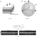
- FIG. 2A An exemplary sample is shown in FIG. 2A , which contains three layers having distinct optic axes.
- the round-trip polarization states' evolution in the sample layer of interest is shown in FIG. 2B .
- the layer of interest is the third layer, which is the lowest/deepest of the three layers and is labeled in FIG. 2A .
- the polarization states 201 and 203 are measured from the light backscattered from the upper and lower surfaces of the layer of interest.
- a rotation circle 202 is constructed, which is the birefringence rotation circle of the layer of interest.
- the rotation angle is the local retardation and the rotation axis is the apparent optic axis.
- Table 1 describes individual steps of the data processing method to recover depth-resolved birefringence information from measurements with a single input state PS-OCT system.
- the spectral interference fringes recorded by spectrometers 119 and 120 are pre-processed with algorithms that are typically used in conventional Fourier domain OCT, including steps such as background subtraction, k-space resampling, and/or dispersion compensation.
- the pre-processed fringes from spectrometers corresponding to a scan of the x-y plane are denoted as H ( x , y , ⁇ ), V ( x , y , ⁇ ) .
- Step 1 Obtain pre-processed fringes H ( x , y , ⁇ ), V ( x , y , ⁇ ) from the spectrometers 119 and 120 in Fig. 1 .
- Step 2 Calculate the depth field profiles E H ( x, y, z ), E V ( x, y, z ) and depth intensity profile I ( z ).
- F() is the Fourier transform and * indicate complex conjugation.
- S A S OA S OA ⁇ cos ⁇ S OA , S n x , y , z + ⁇ z where ⁇ (, ) represents the acute angle between two vectors.
- r ( x, y, z ) ⁇ (( S n ( x , y, z - ⁇ z ) - S A ( x, y, z ), S n ( x, y, z + ⁇ z ) - S A ( x, y, z))
- r ( x , y , z ) is the local retardation, i.e. the retardance accrued over the distance 2 ⁇ z , expressed in angle per distance.
- a birefringence phantom with layers and regions of distinct optic axis orientation and birefringence is imaged and, as shown in FIG. 3 (top), the birefringent regions 301 and 302 have different optic axes.
- a conventional single input state PS-OCT implementation (lower right panel) is unable to resolve the true local birefringence of a region which is below a birefringent layer.
- the true birefringence can be identified within the phantom.
- Embodiments of the invention can provide higher resolution images with the same contrast as current state of the art two-input state PS-OCT.
- the costs associated with apparatus that are implemented in accordance with this invention are significantly lower than current devices and such apparatus are able to provide resolution that is not limited by the polarization modulator.
- FIG. 4 shows a same phantom imaged by two-input PS-OCT (left panel) and the present invention (right panel).
- embodiments of the present invention enable local birefringence contrast with single input state single shot polarization sensitive OCT.
- Known single input PS-OCT procedures do not reconstruct the local birefringence contrast but instead provide the cumulative birefringence contrast, which fails to visualize valuable local tissue structural information.
- Polarization offers a compelling contrast mechanism for diverse applications from remote sensing to biomedical optics.
- multiple input polarization states are required to fully characterize the polarization properties of a sample. It was observed that the polarization state of backscattered or reflected light, when measured through identical illumination and detection paths, frequently aligns with the employed input polarization state 'mirrored' by the horizontal plane of the Poincaré sphere.
- PS-OCT polarization sensitive optical coherence tomography
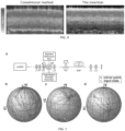
- the effect of P on the input state can be described by a rotation vector ⁇ ( P ) lying in the QU -plane of the Poincaré sphere, with its direction indicating the rotation axis, and its length defining the amount of rotation.
- the rotation vectors of all possible linear retarders are confined to a circle with a radius of ⁇ within the QU -plane ( FIG. 6 , panel (b)).
- ⁇ ( P ) traces out an intricate path in the QU -plane, as shown by the green line in FIG. 6 , panel (b) for simulation of a synchronous movement of the three paddles.
- PS-OCT PS-OCT
- tissue can be modeled as a sequence of homogeneous linearly birefringent layers with distinct optic axis orientations.
- the parameter A describes the combined effect of system components and preceding tissue layers.
- the resulting rotation vectors ⁇ ( P ) describe regular curves across the ⁇ -circle (blue curves in FIG. 6 , panel (b)).
- FIG. 7 panel (a)
- FIG. 7 panels (b)-(d) show the depth-dependent polarization states measured with PS-OCT for three distinct input polarization states. Fitting circles to the polarization state evolution within each layer demonstrates a close match and all circles evolve through the polarization mirror state u', as expected.
- a persistent challenge in single-input-state PS-OCT is to measure the sample's local retardation, i.e. the derivative of the retardance of P ( x ) with depth, which is given by the norm of
- the norm of
- 1.
- ⁇ is the angle between the rotation vector ⁇ and the polarization state v and is needed to deduce local retardation.
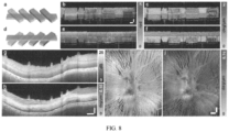
- FIG. 8 panels (a) and (d)).
- FIG. 8 panels (b) and (e) present the cumulative retardation images from either side of the sample, corresponding to the retardation of P ( x ) reconstructed with conventional algorithms for single-input-state PS-OCT.
- FIG. 8 panels (c) and (f) show images of local retardation reconstructed using the polarization mirror state. Whereas cumulative retardation is difficult to interpret, the local retardation clearly reveals the individual sample segments with their distinct levels of birefringence and is recovered irrespective of the sample orientation.
- FIG. 8 panels (g)-(j) demonstrate local retardation imaging of excised swine retina.
- the intensity image visualizes the layered structure of the retina ( FIG. 8 , panel (g)).
- the local retardation reveals the birefringence of the retinal nerve fiber layer (RNFL), clearly differentiating it from the less birefringent subsequent layers ( FIG. 8 , panel (h)).
- RNFL birefringence is being investigated for its potential in diagnosing early degeneration of the RNFL associated with glaucoma.
- the unitary matrix C simply rotates this polarization state evolution and maps the apparent mirror state to the observed mirror state C ⁇ D ⁇ B ⁇ u.
- the 'input' polarization state observed at the receiver in the absence of any sample transmission is C ⁇ B ⁇ u.
- C ⁇ D ⁇ C T defines a new symmetry plane, which is moved from the QU -plane defined by D under the similarity transformation by C. For reconstruction of the local retardation, only the mirror state, not the input state or symmetry plane, is required.
- Using circularly polarized input light requires a half wave of retardation to realize this alignment, which is uncommon in many biological samples. Yet, some tissues feature substantial birefringence and controlling the input state is not necessarily possible.
- the resulting artifacts can be avoided by introducing a modest amount of polarization mode dispersion (PMD) into the system and using spectral binning for reconstruction. As illustrated in FIG. 9 , ⁇ is reconstructed for each individual spectral bin, together with a reliability map expressing the alignment of v with u'.
- PMD polarization mode dispersion
- FIG. 9 shows a demonstration of application of the mirror state constraint in a fiber-based system and removal of the alignment-induced error by using the wavelength-dependence of the polarization states with spectral binning.
- Panel (a) shows a simplified schematic of the sample arm of a fiber-based interferometric imaging system. Ll-L2, lenses, PC, polarization controller, M, scanning mirror, SMF, single mode fiber.
- Panel (b) shows the principle of spectral binning, in which the full spectrum is divided into 9 bins by multiplication with 9 Hanning windows.
- Panel (c) shows an illumination state of polarization (SOP) of each spectral bin. The variation of SOPs is caused by PMD induced by the polarization controller.
- SOP illumination state of polarization
- Panels (d)-(i) show cross-sectional images of two-layer phantom reconstructed with different spectral bins.
- Panel (d) shows local retardation resolved using the 1st spectral bin.
- Panel (e) shows local retardation resolved using the 9th spectral bin.
- Panel (f) shows the reliability metric map of 1st spectral bin.
- Panel (g) shows the reliability metric map of 9th spectral bin.
- Panel (h) shows a cross-sectional birefringence image reconstructed using the whole spectrum.
- Panel (i) shows a cross-sectional birefringence image reconstructed with spectral binning method. Scale bars in panel (i) for panels (d)-(i), vertical: 100 ⁇ m, horizontal: 400 ⁇ m.
- a single-input-state polarization-sensitive spectral domain optical coherence tomography (PS-SD-OCT) system was used for certain embodiments disclosed herein.
- the unpolarized light from a supercontinuum source was linearly polarized, adjusted with an achromatic quarter-wave-plate to circular polarization, unless otherwise noted, and split by a free-space beam splitter into reference and sample arms.
- a linear polarizer oriented at 45° in the reference arm defined the reference polarization state independent of the source polarization.
- the light was directed either in free space to the sample and the reference mirror, respectively, or first coupled through 1.5 m of single mode fiber.
- a three-paddle polarization controller was applied in each fiber for polarization management.
- the light was focused with a 30 mm focal length lens, achieving a FWHM spot diameter of ⁇ 8 ⁇ m, and scanned with a galvanometric mirror in both lateral directions.
- a half-wave plate allowed precisely aligning the polarization axes of the sample and reference light with the slow and fast axis of a polarization maintaining (PM) fiber.
- the polarization states of the PM fiber were subsequently split with a polarizing beam splitter towards two identical custom-built spectrometers to record the interference pattern of the horizontal (h) and vertical (v) polarization components, respectively.
- the detected source bandwidth was about 160 nm centered on 840 nm, providing a measured axial resolution of ⁇ 2.5 ⁇ m in air. Recorded spectra were pre-processed by background-subtraction, alignment between the two spectrometers, interpolation to linear wavenumber k , and compensation for dispersion imbalance between the sample and reference arms. Further details of the optical system are provided below.
- filtering was also performed in the second lateral direction, using the same kernel.
- Swine eyes were collected from a butcher and imaging was carried out within two hours after the eyeball was harvested.
- the scanning area centered on the optical nerve head.
- ⁇ the Kronecker tensor product
- J is the complex conjugate of J
- U ⁇ represents the conjugate transpose of U , corresponding also to its inverse.
- the corresponding SO(3) rotation matrix is:
- u and v clearly define a single rotation axis. Only for the mirror polarization state, in which case both the nominator and denominator vanish, ⁇ is undefined and can take any value.
- ⁇ is undefined and can take any value.
- p [cos ⁇ , sin ⁇ , 0] T
- p T ⁇ u p T ⁇ v by construction.
- a defined rotation vector ⁇ within the QU -plane maps u onto a general v.
- q ⁇ is not only skew-symmetric, but also D -transpose symmetric, confining q to the QU -plane.
- the similarity transformation of q ⁇ by D ⁇ A T ⁇ M T ⁇ D rotates the apparent optic axis q out of the QU-plane, in general.
- ⁇ x determines the amount of retardance of the linear retarder exp ( ⁇ x ⁇ q ⁇ ).
- FIG. 12 shows a setup that may be used in various embodiments disclosed herein.
- SCL Supercontinuum laser
- Ll-L15 Lenses
- P1-P2 Polarizers
- Q1 Quarter wave plate
- H1 Half wave plate
- BS Beam splitter
- PBS Polarizing beam splitter
- SP Spectrometers
- M1-M5 Mirrors
- FM1-FM2 Flip mirrors
- PC1-PC2 Polarization controllers
- SMF single mode fiber
- PMF polarization maintaining fiber
- DC Dispersion compensation.
- SCL supercontinuum laser, DK-3460, NKT Photonics Inc.
- P1,P2 Polarizer, LPNIRE100-B, Thorlabs Inc.
- SMF Single-mode fiber, 780HP, Thorlabs Inc.
- PMF polarization maintaining fiber, P3-780PM-FC-2, Thorlabs Inc.
- PC Polarization controller. Three-paddle polarization controllers, with 1, 2 and 1 fiber loops in the three paddles, respectively.
- a computing device 1310 can receive polarization data from a detector 1302 such as a detector associated with a PS-OCT system.
- computing device 1310 can execute at least a portion of a retardance determination system 1304 to determine retardance of a layer of a sample based on the polarization data received from the detector 1302.
- computing device 1310 can communicate information about the polarization data received from the detector 1302 to a server 1320 over a communication network 1306, which can execute at least a portion of retardance determination system 1304 to determine retardance of a layer of a sample based on the polarization data received from the detector 1302.
- server 1320 can return information to computing device 1310 (and/or any other suitable computing device) indicative of an output of retardance determination system 1304. This information may be transmitted and/or presented to a user (e.g. an operator, a clinician, etc.) and/or may be stored (e.g. as part of a medical record associated with the subject).
- computing device 1310 and/or server 1320 can be any suitable computing device or combination of devices, such as a desktop computer, a laptop computer, a smartphone, a tablet computer, a wearable computer, a server computer, a virtual machine being executed by a physical computing device, etc.
- detector 1302 can be any suitable detector for use with performing polarization-sensitive optical coherence tomography (PS-OCT).
- interferometric detector 1302 can be local to computing device 1310.
- detector 1302 may be incorporated with computing device 1310 (e.g., computing device 1310 can be configured as part of a device for detecting light as part of a PS-OCT system).
- detector 1302 may be connected to computing device 1310 by a cable, a direct wireless link, etc.
- detector 1302 can be located locally and/or remotely from computing device 1310, and can communicate polarization information to computing device 1310 (and/or server 1320) via a communication network (e.g., communication network 1306).
- a communication network e.g., communication network 1306
- communication network 1306 can be any suitable communication network or combination of communication networks.
- communication network 1306 can include a Wi-Fi network (which can include one or more wireless routers, one or more switches, etc.), a peer-to-peer network (e.g., a Bluetooth network), a cellular network (e.g., a 3G network, a 4G network, a 5G network, etc., complying with any suitable standard, such as CDMA, GSM, LTE, LTE Advanced, WiMAX, etc.), a wired network, etc.
- Wi-Fi network which can include one or more wireless routers, one or more switches, etc.
- peer-to-peer network e.g., a Bluetooth network
- a cellular network e.g., a 3G network, a 4G network, a 5G network, etc., complying with any suitable standard, such as CDMA, GSM, LTE, LTE Advanced, WiMAX, etc.
- a wired network etc.
- communication network 1306 can be a local area network, a wide area network, a public network (e.g., the Internet), a private or semi-private network (e.g., a corporate or university intranet), any other suitable type of network, or any suitable combination of networks.
- Communications links shown in FIG. 13 can each be any suitable communications link or combination of communications links, such as wired links, fiber optic links, Wi-Fi links, Bluetooth links, cellular links, etc.
- FIG. 14 shows an example 1400 of hardware that can be used to implement computing device 1310 and server 1320 in accordance with some embodiments of the disclosed subject matter.
- computing device 1310 can include a processor 1402, a display 1404, one or more inputs 1406, one or more communication systems 1408, and/or memory 1410.
- processor 1402 can be any suitable hardware processor or combination of processors, such as a central processing unit, a graphics processing unit, etc.
- display 1404 can include any suitable display devices, such as a computer monitor, a touchscreen, a television, etc.
- inputs 1406 can include any suitable input devices and/or sensors that can be used to receive user input, such as a keyboard, a mouse, a touchscreen, a microphone, etc.
- communications systems 1408 can include any suitable hardware, firmware, and/or software for communicating information over communication network 1306 and/or any other suitable communication networks.
- communications systems 1408 can include one or more transceivers, one or more communication chips and/or chip sets, etc.
- communications systems 1408 can include hardware, firmware and/or software that can be used to establish a Wi-Fi connection, a Bluetooth connection, a cellular connection, an Ethernet connection, etc.
- memory 1410 can include any suitable storage device or devices that can be used to store instructions, values, etc., that can be used, for example, by processor 1402 to present content using display 1404, to communicate with server 1320 via communications system(s) 1408, etc.
- Memory 1410 can include any suitable volatile memory, non-volatile memory, storage, or any suitable combination thereof.
- memory 1410 can include RAM, ROM, EEPROM, one or more flash drives, one or more hard disks, one or more solid state drives, one or more optical drives, etc.
- memory 1410 can have encoded thereon a computer program for controlling operation of computing device 1310.
- processor 1402 can execute at least a portion of the computer program to present content (e.g., images, user interfaces, graphics, tables, etc.), receive content from server 1320, transmit information to server 1320, etc.
- server 1320 can include a processor 1412, a display 1414, one or more inputs 1416, one or more communications systems 1418, and/or memory 1420.
- processor 1412 can be any suitable hardware processor or combination of processors, such as a central processing unit, a graphics processing unit, etc.
- display 1414 can include any suitable display devices, such as a computer monitor, a touchscreen, a television, etc.
- inputs 1416 can include any suitable input devices and/or sensors that can be used to receive user input, such as a keyboard, a mouse, a touchscreen, a microphone, etc.
- communications systems 1418 can include any suitable hardware, firmware, and/or software for communicating information over communication network 1306 and/or any other suitable communication networks.
- communications systems 1418 can include one or more transceivers, one or more communication chips and/or chip sets, etc.
- communications systems 1418 can include hardware, firmware and/or software that can be used to establish a Wi-Fi connection, a Bluetooth connection, a cellular connection, an Ethernet connection, etc.
- memory 1420 can include any suitable storage device or devices that can be used to store instructions, values, etc., that can be used, for example, by processor 1412 to present content using display 1414, to communicate with one or more computing devices 1310, etc.
- Memory 1420 can include any suitable volatile memory, non-volatile memory, storage, or any suitable combination thereof.
- memory 1420 can include RAM, ROM, EEPROM, one or more flash drives, one or more hard disks, one or more solid state drives, one or more optical drives, etc.
- memory 1420 can have encoded thereon a server program for controlling operation of server 1320.
- processor 1412 can execute at least a portion of the server program to transmit information and/or content (e.g., results of a tissue identification and/or classification, a user interface, etc.) to one or more computing devices 1310, receive information and/or content from one or more computing devices 1310, receive instructions from one or more devices (e.g., a personal computer, a laptop computer, a tablet computer, a smartphone, etc.), etc.
- information and/or content e.g., results of a tissue identification and/or classification, a user interface, etc.
- processor 1412 can execute at least a portion of the server program to transmit information and/or content (e.g., results of a tissue identification and/or classification, a user interface, etc.) to one or more computing devices 1310, receive information and/or content from one or more computing devices 1310, receive instructions from one or more devices (e.g., a personal computer, a laptop computer, a tablet computer, a smartphone, etc.), etc.
- devices e.g
- any suitable computer readable media can be used for storing instructions for performing the functions and/or processes described herein.
- computer readable media can be transitory or non-transitory.
- non-transitory computer readable media can include media such as magnetic media (such as hard disks, floppy disks, etc.), optical media (such as compact discs, digital video discs, Blu-ray discs, etc.), semiconductor media (such as RAM, Flash memory, electrically programmable read only memory (EPROM), electrically erasable programmable read only memory (EEPROM), etc.), any suitable media that is not fleeting or devoid of any semblance of permanence during transmission, and/or any suitable tangible media.
- magnetic media such as hard disks, floppy disks, etc.
- optical media such as compact discs, digital video discs, Blu-ray discs, etc.
- semiconductor media such as RAM, Flash memory, electrically programmable read only memory (EPROM), electrically erasable programmable read only memory (EEPROM), etc.
- transitory computer readable media can include signals on networks, in wires, conductors, optical fibers, circuits, or any suitable media that is fleeting and devoid of any semblance of permanence during transmission, and/or any suitable intangible media.
- mechanism can encompass hardware, software, firmware, or any suitable combination thereof.
- FIG. 15 shows an example 1500 of a process for determining a retardance of a layer of a sample in accordance with some embodiments of the disclosed subject matter.
- process 1500 can transmit a first portion of a polarized light to a sample arm of an optical system and a second portion of the polarized light to a reference arm of the optical system.
- process 1500 can combine first return light returned from the sample arm and second return light from the reference arm.
- process 1500 can detect the combined light along a first polarization state and a second polarization state to produce polarization data, where the second polarization state may be different from the first polarization state.
- process 1500 can determine polarization states of light returning from upper and lower surfaces of a layer of the sample based on detecting the combined light. Finally, at 1510, process 1500 can determine a retardance of the layer of the sample based on the determined polarization states.
Landscapes
- Physics & Mathematics (AREA)
- General Physics & Mathematics (AREA)
- General Health & Medical Sciences (AREA)
- Health & Medical Sciences (AREA)
- Analytical Chemistry (AREA)
- Life Sciences & Earth Sciences (AREA)
- Chemical & Material Sciences (AREA)
- Biochemistry (AREA)
- Immunology (AREA)
- Pathology (AREA)
- Radiology & Medical Imaging (AREA)
- Nuclear Medicine, Radiotherapy & Molecular Imaging (AREA)
- Optics & Photonics (AREA)
- Investigating Or Analysing Materials By Optical Means (AREA)
- Eye Examination Apparatus (AREA)
- Endoscopes (AREA)
Claims (18)
- Verfahren zur Bestimmung der Retardierung einer Schicht einer Probe, umfassend:Übertragen eines ersten Teils eines polarisierten Lichts zu einem Probenarm (S) eines optischen Systems (100) und eines zweiten Teils des polarisierten Lichts zu einem Referenzarm (R) des optischen Systems;Kombinieren von erstem Rückkehrlicht, das von dem Probenarm (S) zurückkehrt, und zweitem Rückkehrlicht von dem Referenzarm (R);Erfassen, unter Verwendung eines Detektors (119, 120), des kombinierten Lichts entlang eines ersten Polarisationszustands und eines zweiten Polarisationszustands, um Polarisationsdaten zu erzeugen,wobei der zweite Polarisationszustand von dem ersten Polarisationszustand verschieden ist;Bestimmen, unter Verwendung eines Prozessors (1402), der mit dem Detektor (119, 120) gekoppelt ist, von Polarisationszuständen von Licht, das von oberen und unteren Oberflächen einer Schicht der Probe zurückkehrt, basierend auf der Erfassung des kombinierten Lichts;dadurch gekennzeichnet, dass das Verfahren umfasst:Bestimmen, unter Verwendung des Prozessors (1042), einer Retardierung der Schicht der Probe auf der Grundlage der bestimmten Polarisationszustände durch Bestimmen eines Spiegelzustands, der mit den Polarisationsdaten verbunden ist,wobei der Spiegelzustand einen Punkt auf einer Poincaré-Kugel umfasst.
- Verfahren nach Anspruch 1, wobei der Spiegelzustand umfasst:
einen Eingangspolarisationszustand mit umgekehrter Helizität. - Verfahren nach einem der Ansprüche 1 bis 3, wobei die Schicht der Probe eine unter der Oberfläche liegende Schicht der Probe umfasst.
- Verfahren nach einem der Ansprüche 1-3, wobei das optische System (100) ein optisches Kohärenztomographiesystem umfasst, und
wobei das Detektieren des kombinierten Lichts entlang eines ersten Polarisationszustands und eines zweiten Polarisationszustands ferner umfasst:
Erfassen des kombinierten Lichts entlang eines ersten Polarisationszustands und eines zweiten Polarisationszustands unter Verwendung des optischen Kohärenztomographiesystems. - Verfahren nach einem der Ansprüche 1 bis 4, wobei die Bestimmung der Polarisationszustände von Licht, das von den oberen und unteren Oberflächen einer Schicht der Probe zurückkehrt, ferner umfasst:Bestimmen eines Rotationswinkels und einer Rotationsachse eines Rotationskreises, der mit den Polarisationszuständen von oberen und unteren Oberflächen der Schicht der Probe assoziiert ist, undBestimmen eines Retardierungsgrades und einer scheinbaren optischen Achse auf der Grundlage der Bestimmung des Rotationswinkels bzw. der Rotationsachse, wobei der Rotationskreis auf der Poincaré-Kugel liegt.
- Verfahren nach einem der Ansprüche 1 bis 5, wobei die Probe eine Vielzahl von Schichten umfasst, und
wobei das Bestimmen einer Retardierung einer Schicht der Probe auf der Grundlage der ermittelten Polarisationszustände ferner umfasst:
Bestimmen einer Retardierung jeder der Vielzahl von Schichten der Probe auf der Grundlage der bestimmten Polarisationszustände, und wobei das Verfahren weiterhin umfasst:
Erzeugen einer Rekonstruktion der Probe basierend auf der Retardierung jeder der Vielzahl von Schichten der Probe. - Verfahren nach einem der Ansprüche 1 bis 6, wobei das Bestimmen einer Retardierung einer Schicht der Probe ferner umfasst:
Bestimmen der Retardierung der Schicht der Probe unter Verwendung der Wellenlängenabhängigkeit der Polarisationszustände, um Artefakte zu reduzieren. - Verfahren nach Anspruch 7, wobei die Bestimmung der Retardierung der Schicht der Probe unter Verwendung der Wellenlängenabhängigkeit der Polarisationszustände zur Verringerung von Artefakten weiterhin umfasst:
Bestimmen der Retardierung der Schicht der Probe unter Verwendung der Wellenlängenabhängigkeit der Polarisationszustände zur Reduzierung von Artefakten auf der Grundlage von spektralem Binning. - Verfahren nach einem der Ansprüche 1-8, wobei der Detektor (119, 120) einen ersten Detektor und einen zweiten Detektor umfasst, und wobei das Detektieren des kombinierten Lichts entlang eines ersten Polarisationszustands und eines zweiten Polarisationszustands zum Erzeugen von Polarisationsdaten weiterhin umfasst:Übertragen des kombinierten Lichts zu einem polarisierenden Strahlenteiler,wobei der polarisierende Strahlenteiler Licht mit dem ersten Polarisationszustand zu dem ersten Detektor und Licht mit dem zweiten Polarisationszustand zu dem zweiten Detektor überträgt.
- Vorrichtung (100) zum Bestimmen einer Retardierung einer Schicht einer Probe, umfassend:ein interferometrisches optisches System mit einem Probenarm (S) und einem Referenzarm (R);eine Lichtquelle (101), die mit dem optischen System gekoppelt ist, wobei die Lichtquelle so konfiguriert ist, dass sie einen ersten Teil eines polarisierten Lichts an den Probenarm (S) und einen zweiten Teil des polarisierten Lichts an den Referenzarm (R) bereitstellt, und das optische System so konfiguriert ist, dass es das erste Rückkehrlicht, das vom Probenarm (S) zurückkehrt, und das zweite Rückkehrlicht vom Referenzarm (R) kombiniert;einen Detektor (119, 120) zum Erfassen des kombinierten Lichts entlang eines ersten Polarisationszustands und eines zweiten Polarisationszustands, um Polarisationsdaten zu erzeugen,wobei sich der zweite Polarisationszustand von dem ersten Polarisationszustand unterscheidet; undeinen Prozessor (1402), der mit dem Detektor (119, 120) gekoppelt ist, wobei der Prozessor so konfiguriert ist, um Polarisationszustände von Licht zu bestimmen, das von oberen und unteren Oberflächen einer Schicht der Probe zurückkehrt, basierend auf dem Detektor, der das kombinierte Licht erfasst,dadurch gekennzeichnet, dass der Prozessor weiterhin konfiguriert ist, um eine Retardierung der Schicht der Probe auf der Grundlage der bestimmten Polarisationszustände zu bestimmen, durch Bestimmen eines Spiegelzustands, der mit den Polarisationsdaten assoziiert ist, wobei der Spiegelzustand einen Punkt auf einer Poincaré-Kugel umfasst.
- Vorrichtung nach Anspruch 10, wobei der Spiegelzustand umfasst:
einen Eingangspolarisationszustand mit umgekehrter Helizität. - Vorrichtung nach einem der Ansprüche 10-11, wobei die Schicht der Probe eine unter der Oberfläche liegende Schicht der Probe umfasst.
- Vorrichtung nach einem der Ansprüche 10-12, wobei das optische System ein optisches Kohärenztomographiesystem umfasst, und
wobei der Prozessor (1402), wenn er das kombinierte Licht entlang eines ersten Polarisationszustands und eines zweiten Polarisationszustands detektiert, ferner so konfiguriert ist, um das kombinierte Licht entlang eines ersten Polarisationszustands und eines zweiten Polarisationszustands unter Verwendung des optischen Kohärenztomographiesystems zu detektieren. - Vorrichtung nach einem der Ansprüche 10 bis 13, wobei der Prozessor (1402) beim Bestimmen von Polarisationszuständen von Licht, das von oberen und unteren Oberflächen einer Schicht der Probe zurückkehrt, weiterhin konfiguriert ist, zum:Bestimmen eines Rotationswinkels und einer Rotationsachse eines Rotationskreises,die mit den Polarisationszuständen von oberen und unteren Oberflächen der Schicht der Probe assoziiert sind, undBestimmen eines Retardierungsgrades und einer scheinbaren optischen Achse auf der Grundlage der Bestimmung des Rotationswinkels bzw. der Rotationsachse, wobei der Rotationskreis auf der Poincaré-Kugel liegt.
- Vorrichtung nach einem der Ansprüche 10-14, wobei die Probe eine Vielzahl von Schichten umfasst, undwobei der Prozessor (1402), wenn er eine Retardierung einer Schicht der Probe auf der Grundlage der bestimmten Polarisationszustände bestimmt, ferner konfiguriert ist, zum: Bestimmen einer Retardierung jeder der Vielzahl von Schichten der Probe auf der Grundlage der bestimmten Polarisationszustände, undwobei der Prozessor (1402) weiterhin konfiguriert ist, zum:
Erzeugen einer Rekonstruktion der Probe auf der Grundlage der Retardierung jeder der Vielzahl von Schichten der Probe. - Vorrichtung nach einem der Ansprüche 10 bis 15, wobei der Prozessor (1402), wenn er eine Retardierung einer Schicht der Probe bestimmt, ferner konfiguriert ist, zum:
Bestimmen der Retardierung der Schicht der Probe unter Verwendung der Wellenlängenabhängigkeit der Polarisationszustände, um Artefakte zu reduzieren. - Vorrichtung nach Anspruch 16, wobei der Prozessor, wenn er die Retardierung der Schicht der Probe unter Verwendung der Wellenlängenabhängigkeit der Polarisationszustände bestimmt, um Artefakte zu reduzieren, weiterhin konfiguriert ist, zum:
Bestimmen der Retardierung der Schicht der Probe unter Verwendung der Wellenlängenabhängigkeit der Polarisationszustände, um Artefakte auf der Grundlage von spektralem Binning zu reduzieren. - Vorrichtung nach einem der Ansprüche 10-17, wobei der Detektor (119, 120) einen ersten Detektor und einen zweiten Detektor umfasst, undwobei die Vorrichtung so konfiguriert ist, dass sie kombiniertes Licht zu einem polarisierenden Strahlenteiler überträgt,wobei der polarisierende Strahlteiler so konfiguriert ist, dass er Licht mit dem ersten Polarisationszustand zu dem ersten Detektor und Licht mit dem zweiten Polarisationszustand zu dem zweiten Detektor überträgt.
Applications Claiming Priority (2)
| Application Number | Priority Date | Filing Date | Title |
|---|---|---|---|
| US201862744917P | 2018-10-12 | 2018-10-12 | |
| PCT/US2019/056048 WO2020077328A1 (en) | 2018-10-12 | 2019-10-14 | Method and apparatus for measuring depth-resolved tissue birefringence using single input state polarization sensitive optical coherence tomography |
Publications (3)
| Publication Number | Publication Date |
|---|---|
| EP3864459A1 EP3864459A1 (de) | 2021-08-18 |
| EP3864459A4 EP3864459A4 (de) | 2022-08-10 |
| EP3864459B1 true EP3864459B1 (de) | 2024-09-25 |
Family
ID=70164804
Family Applications (1)
| Application Number | Title | Priority Date | Filing Date |
|---|---|---|---|
| EP19870605.3A Active EP3864459B1 (de) | 2018-10-12 | 2019-10-14 | Verfahren und vorrichtung zur messung der tiefenaufgelösten gewebedoppelbrechung unter verwendung einer gegenüber einzeleingabestatus-polarisierung empfindlichen optischen kohärenztomografie |
Country Status (4)
| Country | Link |
|---|---|
| US (1) | US11473897B2 (de) |
| EP (1) | EP3864459B1 (de) |
| JP (2) | JP7620925B2 (de) |
| WO (1) | WO2020077328A1 (de) |
Families Citing this family (8)
| Publication number | Priority date | Publication date | Assignee | Title |
|---|---|---|---|---|
| EP3730897A1 (de) * | 2019-04-25 | 2020-10-28 | Nokia Technologies Oy | Vorrichtung, systeme und verfahren zur detektion von licht |
| JP7479179B2 (ja) * | 2020-04-07 | 2024-05-08 | 株式会社タムロン | 光学系、眼底検査装置、眼底撮像装置、及び眼底検査システム |
| JP2023542895A (ja) * | 2020-09-17 | 2023-10-12 | シンガポール・ヘルス・サービシーズ・ピーティーイー・リミテッド | 偏光感受型光コヒーレンストモグラフィ用の方法とシステム |
| WO2022155270A1 (en) * | 2021-01-12 | 2022-07-21 | The Board Of Trustees Of The University Of Illinois | Multiphase optical coherence microscopy imaging |
| FR3123122B1 (fr) * | 2021-05-20 | 2023-12-15 | KAMAX Innovative Systems | Dispositif de mesure d’informations polarimétriques et de fluorescence |
| EP4206651B1 (de) * | 2021-12-28 | 2026-01-28 | Tata Consultancy Services Limited | Verfahren und vorrichtung zur polarimetrischen mueller-matrix-charakterisierung transparenter objekte |
| CN115196045B (zh) * | 2022-09-15 | 2023-01-13 | 北京星河动力装备科技有限公司 | 地表探测方法、装置、运载火箭、电子设备和存储介质 |
| WO2025259837A1 (en) * | 2024-06-14 | 2025-12-18 | University Of Washington | Guided multimodal polarization-sensitive optical coherence tomography |
Family Cites Families (20)
| Publication number | Priority date | Publication date | Assignee | Title |
|---|---|---|---|---|
| US5822035A (en) * | 1996-08-30 | 1998-10-13 | Heidelberg Engineering Optische Messysteme Gmbh | Ellipsometer |
| US6208415B1 (en) * | 1997-06-12 | 2001-03-27 | The Regents Of The University Of California | Birefringence imaging in biological tissue using polarization sensitive optical coherent tomography |
| JP3436704B2 (ja) * | 1999-03-03 | 2003-08-18 | 株式会社リコー | 複屈折測定方法及びその装置 |
| GB0100819D0 (en) * | 2001-01-12 | 2001-02-21 | Hewlett Packard Co | Optical characterization of retarding devices |
| US7826059B2 (en) | 2001-01-22 | 2010-11-02 | Roth Jonathan E | Method and apparatus for polarization-sensitive optical coherence tomography |
| US6961123B1 (en) | 2001-09-28 | 2005-11-01 | The Texas A&M University System | Method and apparatus for obtaining information from polarization-sensitive optical coherence tomography |
| US20060038999A1 (en) * | 2002-10-25 | 2006-02-23 | Christian Hentschel | Polarization conversion unit for reducing polarization dependent measurement errors |
| US6927860B2 (en) * | 2003-05-19 | 2005-08-09 | Oti Ophthalmic Technologies Inc. | Optical mapping apparatus with optimized OCT configuration |
| US20080007734A1 (en) | 2004-10-29 | 2008-01-10 | The General Hospital Corporation | System and method for providing Jones matrix-based analysis to determine non-depolarizing polarization parameters using polarization-sensitive optical coherence tomography |
| US20070109554A1 (en) * | 2005-11-14 | 2007-05-17 | Feldchtein Felix I | Polarization sensitive optical coherence device for obtaining birefringence information |
| JP4344829B2 (ja) * | 2006-05-02 | 2009-10-14 | 国立大学法人 筑波大学 | 偏光感受光画像計測装置 |
| US8125648B2 (en) * | 2006-06-05 | 2012-02-28 | Board Of Regents, The University Of Texas System | Polarization-sensitive spectral interferometry |
| US9086264B2 (en) * | 2007-06-06 | 2015-07-21 | Oregon Health & Science University | Polarization sensitive spectral domain OCT using an interference signal modulated at a constant frequency and a two-path reference arm with a single reference mirror |
| US7837833B2 (en) * | 2007-10-23 | 2010-11-23 | Honeywell Asca Inc. | Method for characterizing fibrous materials using stokes parameters |
| JP5787255B2 (ja) * | 2011-07-12 | 2015-09-30 | 国立大学法人 筑波大学 | Ps−octの計測データを補正するプログラム及び該プログラムを搭載したps−octシステム |
| US9885557B2 (en) | 2013-10-11 | 2018-02-06 | Case Western Reserve University | Polarization sensitive optical coherence tomography using multiple polarization sensitive semiconductor optical amplifiers |
| JP6256879B2 (ja) * | 2014-06-06 | 2018-01-10 | 国立大学法人 筑波大学 | 偏光感受型光画像計測システム及び該システムに搭載されたプログラム |
| KR102329767B1 (ko) | 2015-01-22 | 2021-11-23 | 엘지전자 주식회사 | 편광 민감도 광간섭성 단층 촬영 장치 및 그 제어방법 |
| JP6606800B2 (ja) * | 2015-04-23 | 2019-11-20 | 株式会社トーメーコーポレーション | 偏光情報を利用した光干渉断層計 |
| EP3465336B1 (de) | 2016-06-03 | 2020-09-30 | Gentex Corporation | Anzeigesystem mit phasenausgerichteter reflektierender steuerung |
-
2019
- 2019-10-14 US US17/284,641 patent/US11473897B2/en active Active
- 2019-10-14 EP EP19870605.3A patent/EP3864459B1/de active Active
- 2019-10-14 WO PCT/US2019/056048 patent/WO2020077328A1/en not_active Ceased
- 2019-10-14 JP JP2021545271A patent/JP7620925B2/ja active Active
-
2024
- 2024-12-27 JP JP2024232241A patent/JP2025060957A/ja active Pending
Also Published As
| Publication number | Publication date |
|---|---|
| WO2020077328A1 (en) | 2020-04-16 |
| JP2022508703A (ja) | 2022-01-19 |
| US11473897B2 (en) | 2022-10-18 |
| EP3864459A4 (de) | 2022-08-10 |
| JP2025060957A (ja) | 2025-04-10 |
| EP3864459A1 (de) | 2021-08-18 |
| JP7620925B2 (ja) | 2025-01-24 |
| US20210396509A1 (en) | 2021-12-23 |
Similar Documents
| Publication | Publication Date | Title |
|---|---|---|
| EP3864459B1 (de) | Verfahren und vorrichtung zur messung der tiefenaufgelösten gewebedoppelbrechung unter verwendung einer gegenüber einzeleingabestatus-polarisierung empfindlichen optischen kohärenztomografie | |
| Ramella-Roman et al. | A review of polarization-based imaging technologies for clinical and preclinical applications | |
| US10470655B2 (en) | Ocular metrology employing spectral wavefront analysis of reflected light | |
| US9330092B2 (en) | Systems, methods, apparatus and computer-accessible-medium for providing polarization-mode dispersion compensation in optical coherence tomography | |
| JP6606800B2 (ja) | 偏光情報を利用した光干渉断層計 | |
| US7612880B2 (en) | Advanced polarization imaging method, apparatus, and computer program product for retinal imaging, liquid crystal testing, active remote sensing, and other applications | |
| US9226655B2 (en) | Image processing apparatus and image processing method | |
| CN106461538A (zh) | 偏振敏感光学图像测量系统以及搭载于该系统上的程序 | |
| JP2022506821A (ja) | 光学系を特性評価するおよび光学系で撮像する方法 | |
| US8797551B2 (en) | Compact, affordable optical test, measurement or imaging device | |
| EP3015816B1 (de) | Polarisationsempfindliche optische kohärenztomografiebildgebungsvorrichtung | |
| JP2016083245A (ja) | 光断層撮影装置 | |
| JP2010151684A (ja) | 局所的な複屈折情報を抽出可能な偏光感受光画像計測装置 | |
| JP6542178B2 (ja) | 偏光情報を利用した光断層画像撮影装置 | |
| WO2012129404A1 (en) | Determination of a material characteristics with the use of second-order photon correlations | |
| CN116671860A (zh) | 一种基于偏振敏感光学相干层析术的全眼成像方法及系统 | |
| JP2016003898A (ja) | 光断層画像撮影装置 | |
| Wang | Improving optical coherence tomography theories and techniques for advanced performance and reduced cost | |
| JP2024131552A (ja) | 教師データ生成システム、機械学習システム、octシステム、教師データ生成方法および教師データ生成プログラム | |
| Xiong | Development of single input polarization-sensitive optical coherence tomography, towards local birefringence imaging with high resolution and lower cost | |
| Li et al. | Accurately differentiating inflamed and healthy tissue samples by removing errors and noises in depth-resolved polarization parameter images | |
| CN117129425A (zh) | 一种偏振敏感型光学相干层析成像系统 | |
| Volpato | Polarization Sensitive Optical Coherence Tomography: optimization and application to Zebrafish imaging |
Legal Events
| Date | Code | Title | Description |
|---|---|---|---|
| STAA | Information on the status of an ep patent application or granted ep patent |
Free format text: STATUS: THE INTERNATIONAL PUBLICATION HAS BEEN MADE |
|
| PUAI | Public reference made under article 153(3) epc to a published international application that has entered the european phase |
Free format text: ORIGINAL CODE: 0009012 |
|
| STAA | Information on the status of an ep patent application or granted ep patent |
Free format text: STATUS: REQUEST FOR EXAMINATION WAS MADE |
|
| 17P | Request for examination filed |
Effective date: 20210510 |
|
| AK | Designated contracting states |
Kind code of ref document: A1 Designated state(s): AL AT BE BG CH CY CZ DE DK EE ES FI FR GB GR HR HU IE IS IT LI LT LU LV MC MK MT NL NO PL PT RO RS SE SI SK SM TR |
|
| DAV | Request for validation of the european patent (deleted) | ||
| DAX | Request for extension of the european patent (deleted) | ||
| A4 | Supplementary search report drawn up and despatched |
Effective date: 20220708 |
|
| RIC1 | Information provided on ipc code assigned before grant |
Ipc: G02B 27/28 20060101AFI20220704BHEP |
|
| P01 | Opt-out of the competence of the unified patent court (upc) registered |
Effective date: 20230526 |
|
| RAP3 | Party data changed (applicant data changed or rights of an application transferred) |
Owner name: NANYANG TECHNOLOGICAL UNIVERSITY Owner name: THE GENERAL HOSPITAL CORPORATION |
|
| GRAP | Despatch of communication of intention to grant a patent |
Free format text: ORIGINAL CODE: EPIDOSNIGR1 |
|
| STAA | Information on the status of an ep patent application or granted ep patent |
Free format text: STATUS: GRANT OF PATENT IS INTENDED |
|
| INTG | Intention to grant announced |
Effective date: 20240425 |
|
| GRAS | Grant fee paid |
Free format text: ORIGINAL CODE: EPIDOSNIGR3 |
|
| GRAA | (expected) grant |
Free format text: ORIGINAL CODE: 0009210 |
|
| STAA | Information on the status of an ep patent application or granted ep patent |
Free format text: STATUS: THE PATENT HAS BEEN GRANTED |
|
| AK | Designated contracting states |
Kind code of ref document: B1 Designated state(s): AL AT BE BG CH CY CZ DE DK EE ES FI FR GB GR HR HU IE IS IT LI LT LU LV MC MK MT NL NO PL PT RO RS SE SI SK SM TR |
|
| REG | Reference to a national code |
Ref country code: GB Ref legal event code: FG4D |
|
| REG | Reference to a national code |
Ref country code: CH Ref legal event code: EP |
|
| REG | Reference to a national code |
Ref country code: DE Ref legal event code: R096 Ref document number: 602019059558 Country of ref document: DE |
|
| REG | Reference to a national code |
Ref country code: IE Ref legal event code: FG4D |
|
| REG | Reference to a national code |
Ref country code: LT Ref legal event code: MG9D |
|
| PG25 | Lapsed in a contracting state [announced via postgrant information from national office to epo] |
Ref country code: NO Free format text: LAPSE BECAUSE OF FAILURE TO SUBMIT A TRANSLATION OF THE DESCRIPTION OR TO PAY THE FEE WITHIN THE PRESCRIBED TIME-LIMIT Effective date: 20241225 |
|
| PG25 | Lapsed in a contracting state [announced via postgrant information from national office to epo] |
Ref country code: GR Free format text: LAPSE BECAUSE OF FAILURE TO SUBMIT A TRANSLATION OF THE DESCRIPTION OR TO PAY THE FEE WITHIN THE PRESCRIBED TIME-LIMIT Effective date: 20241226 Ref country code: FI Free format text: LAPSE BECAUSE OF FAILURE TO SUBMIT A TRANSLATION OF THE DESCRIPTION OR TO PAY THE FEE WITHIN THE PRESCRIBED TIME-LIMIT Effective date: 20240925 |
|
| PG25 | Lapsed in a contracting state [announced via postgrant information from national office to epo] |
Ref country code: BG Free format text: LAPSE BECAUSE OF FAILURE TO SUBMIT A TRANSLATION OF THE DESCRIPTION OR TO PAY THE FEE WITHIN THE PRESCRIBED TIME-LIMIT Effective date: 20240925 |
|
| PG25 | Lapsed in a contracting state [announced via postgrant information from national office to epo] |
Ref country code: LV Free format text: LAPSE BECAUSE OF FAILURE TO SUBMIT A TRANSLATION OF THE DESCRIPTION OR TO PAY THE FEE WITHIN THE PRESCRIBED TIME-LIMIT Effective date: 20240925 |
|
| PG25 | Lapsed in a contracting state [announced via postgrant information from national office to epo] |
Ref country code: RS Free format text: LAPSE BECAUSE OF FAILURE TO SUBMIT A TRANSLATION OF THE DESCRIPTION OR TO PAY THE FEE WITHIN THE PRESCRIBED TIME-LIMIT Effective date: 20241225 |
|
| REG | Reference to a national code |
Ref country code: NL Ref legal event code: MP Effective date: 20240925 |
|
| PG25 | Lapsed in a contracting state [announced via postgrant information from national office to epo] |
Ref country code: RS Free format text: LAPSE BECAUSE OF FAILURE TO SUBMIT A TRANSLATION OF THE DESCRIPTION OR TO PAY THE FEE WITHIN THE PRESCRIBED TIME-LIMIT Effective date: 20241225 Ref country code: NO Free format text: LAPSE BECAUSE OF FAILURE TO SUBMIT A TRANSLATION OF THE DESCRIPTION OR TO PAY THE FEE WITHIN THE PRESCRIBED TIME-LIMIT Effective date: 20241225 Ref country code: LV Free format text: LAPSE BECAUSE OF FAILURE TO SUBMIT A TRANSLATION OF THE DESCRIPTION OR TO PAY THE FEE WITHIN THE PRESCRIBED TIME-LIMIT Effective date: 20240925 Ref country code: GR Free format text: LAPSE BECAUSE OF FAILURE TO SUBMIT A TRANSLATION OF THE DESCRIPTION OR TO PAY THE FEE WITHIN THE PRESCRIBED TIME-LIMIT Effective date: 20241226 Ref country code: FI Free format text: LAPSE BECAUSE OF FAILURE TO SUBMIT A TRANSLATION OF THE DESCRIPTION OR TO PAY THE FEE WITHIN THE PRESCRIBED TIME-LIMIT Effective date: 20240925 Ref country code: BG Free format text: LAPSE BECAUSE OF FAILURE TO SUBMIT A TRANSLATION OF THE DESCRIPTION OR TO PAY THE FEE WITHIN THE PRESCRIBED TIME-LIMIT Effective date: 20240925 |
|
| REG | Reference to a national code |
Ref country code: AT Ref legal event code: MK05 Ref document number: 1727133 Country of ref document: AT Kind code of ref document: T Effective date: 20240925 |
|
| PG25 | Lapsed in a contracting state [announced via postgrant information from national office to epo] |
Ref country code: NL Free format text: LAPSE BECAUSE OF FAILURE TO SUBMIT A TRANSLATION OF THE DESCRIPTION OR TO PAY THE FEE WITHIN THE PRESCRIBED TIME-LIMIT Effective date: 20240925 |
|
| PG25 | Lapsed in a contracting state [announced via postgrant information from national office to epo] |
Ref country code: IS Free format text: LAPSE BECAUSE OF FAILURE TO SUBMIT A TRANSLATION OF THE DESCRIPTION OR TO PAY THE FEE WITHIN THE PRESCRIBED TIME-LIMIT Effective date: 20250125 Ref country code: PT Free format text: LAPSE BECAUSE OF FAILURE TO SUBMIT A TRANSLATION OF THE DESCRIPTION OR TO PAY THE FEE WITHIN THE PRESCRIBED TIME-LIMIT Effective date: 20250127 |
|
| PG25 | Lapsed in a contracting state [announced via postgrant information from national office to epo] |
Ref country code: RO Free format text: LAPSE BECAUSE OF FAILURE TO SUBMIT A TRANSLATION OF THE DESCRIPTION OR TO PAY THE FEE WITHIN THE PRESCRIBED TIME-LIMIT Effective date: 20240925 Ref country code: SM Free format text: LAPSE BECAUSE OF FAILURE TO SUBMIT A TRANSLATION OF THE DESCRIPTION OR TO PAY THE FEE WITHIN THE PRESCRIBED TIME-LIMIT Effective date: 20240925 |
|
| PG25 | Lapsed in a contracting state [announced via postgrant information from national office to epo] |
Ref country code: ES Free format text: LAPSE BECAUSE OF FAILURE TO SUBMIT A TRANSLATION OF THE DESCRIPTION OR TO PAY THE FEE WITHIN THE PRESCRIBED TIME-LIMIT Effective date: 20240925 |
|
| PG25 | Lapsed in a contracting state [announced via postgrant information from national office to epo] |
Ref country code: EE Free format text: LAPSE BECAUSE OF FAILURE TO SUBMIT A TRANSLATION OF THE DESCRIPTION OR TO PAY THE FEE WITHIN THE PRESCRIBED TIME-LIMIT Effective date: 20240925 Ref country code: AT Free format text: LAPSE BECAUSE OF FAILURE TO SUBMIT A TRANSLATION OF THE DESCRIPTION OR TO PAY THE FEE WITHIN THE PRESCRIBED TIME-LIMIT Effective date: 20240925 |
|
| PG25 | Lapsed in a contracting state [announced via postgrant information from national office to epo] |
Ref country code: CZ Free format text: LAPSE BECAUSE OF FAILURE TO SUBMIT A TRANSLATION OF THE DESCRIPTION OR TO PAY THE FEE WITHIN THE PRESCRIBED TIME-LIMIT Effective date: 20240925 Ref country code: PL Free format text: LAPSE BECAUSE OF FAILURE TO SUBMIT A TRANSLATION OF THE DESCRIPTION OR TO PAY THE FEE WITHIN THE PRESCRIBED TIME-LIMIT Effective date: 20240925 |
|
| PG25 | Lapsed in a contracting state [announced via postgrant information from national office to epo] |
Ref country code: IT Free format text: LAPSE BECAUSE OF FAILURE TO SUBMIT A TRANSLATION OF THE DESCRIPTION OR TO PAY THE FEE WITHIN THE PRESCRIBED TIME-LIMIT Effective date: 20240925 Ref country code: SK Free format text: LAPSE BECAUSE OF FAILURE TO SUBMIT A TRANSLATION OF THE DESCRIPTION OR TO PAY THE FEE WITHIN THE PRESCRIBED TIME-LIMIT Effective date: 20240925 |
|
| REG | Reference to a national code |
Ref country code: CH Ref legal event code: PL |
|
| REG | Reference to a national code |
Ref country code: DE Ref legal event code: R097 Ref document number: 602019059558 Country of ref document: DE |
|
| PG25 | Lapsed in a contracting state [announced via postgrant information from national office to epo] |
Ref country code: MC Free format text: LAPSE BECAUSE OF FAILURE TO SUBMIT A TRANSLATION OF THE DESCRIPTION OR TO PAY THE FEE WITHIN THE PRESCRIBED TIME-LIMIT Effective date: 20240925 |
|
| PG25 | Lapsed in a contracting state [announced via postgrant information from national office to epo] |
Ref country code: DK Free format text: LAPSE BECAUSE OF FAILURE TO SUBMIT A TRANSLATION OF THE DESCRIPTION OR TO PAY THE FEE WITHIN THE PRESCRIBED TIME-LIMIT Effective date: 20240925 |
|
| PG25 | Lapsed in a contracting state [announced via postgrant information from national office to epo] |
Ref country code: LU Free format text: LAPSE BECAUSE OF NON-PAYMENT OF DUE FEES Effective date: 20241014 Ref country code: BE Free format text: LAPSE BECAUSE OF NON-PAYMENT OF DUE FEES Effective date: 20241031 |
|
| PG25 | Lapsed in a contracting state [announced via postgrant information from national office to epo] |
Ref country code: CH Free format text: LAPSE BECAUSE OF NON-PAYMENT OF DUE FEES Effective date: 20241031 |
|
| PLBE | No opposition filed within time limit |
Free format text: ORIGINAL CODE: 0009261 |
|
| STAA | Information on the status of an ep patent application or granted ep patent |
Free format text: STATUS: NO OPPOSITION FILED WITHIN TIME LIMIT |
|
| REG | Reference to a national code |
Ref country code: BE Ref legal event code: MM Effective date: 20241031 |
|
| 26N | No opposition filed |
Effective date: 20250626 |
|
| PG25 | Lapsed in a contracting state [announced via postgrant information from national office to epo] |
Ref country code: SE Free format text: LAPSE BECAUSE OF FAILURE TO SUBMIT A TRANSLATION OF THE DESCRIPTION OR TO PAY THE FEE WITHIN THE PRESCRIBED TIME-LIMIT Effective date: 20240925 |
|
| PG25 | Lapsed in a contracting state [announced via postgrant information from national office to epo] |
Ref country code: IE Free format text: LAPSE BECAUSE OF NON-PAYMENT OF DUE FEES Effective date: 20241014 |
|
| PGFP | Annual fee paid to national office [announced via postgrant information from national office to epo] |
Ref country code: DE Payment date: 20251029 Year of fee payment: 7 |
|
| PGFP | Annual fee paid to national office [announced via postgrant information from national office to epo] |
Ref country code: GB Payment date: 20251027 Year of fee payment: 7 |
|
| PG25 | Lapsed in a contracting state [announced via postgrant information from national office to epo] |
Ref country code: HR Free format text: LAPSE BECAUSE OF FAILURE TO SUBMIT A TRANSLATION OF THE DESCRIPTION OR TO PAY THE FEE WITHIN THE PRESCRIBED TIME-LIMIT Effective date: 20240925 |
|
| PGFP | Annual fee paid to national office [announced via postgrant information from national office to epo] |
Ref country code: FR Payment date: 20251027 Year of fee payment: 7 |
|
| PG25 | Lapsed in a contracting state [announced via postgrant information from national office to epo] |
Ref country code: CY Free format text: LAPSE BECAUSE OF FAILURE TO SUBMIT A TRANSLATION OF THE DESCRIPTION OR TO PAY THE FEE WITHIN THE PRESCRIBED TIME-LIMIT; INVALID AB INITIO Effective date: 20191014 |
|
| PG25 | Lapsed in a contracting state [announced via postgrant information from national office to epo] |
Ref country code: HU Free format text: LAPSE BECAUSE OF FAILURE TO SUBMIT A TRANSLATION OF THE DESCRIPTION OR TO PAY THE FEE WITHIN THE PRESCRIBED TIME-LIMIT; INVALID AB INITIO Effective date: 20191014 |