EP3864378B1 - Faseroptischer sensor mit bragg-gitter mit hoher temperaturstabilität und herstellungsverfahren dafür - Google Patents
Faseroptischer sensor mit bragg-gitter mit hoher temperaturstabilität und herstellungsverfahren dafür Download PDFInfo
- Publication number
- EP3864378B1 EP3864378B1 EP19816827.0A EP19816827A EP3864378B1 EP 3864378 B1 EP3864378 B1 EP 3864378B1 EP 19816827 A EP19816827 A EP 19816827A EP 3864378 B1 EP3864378 B1 EP 3864378B1
- Authority
- EP
- European Patent Office
- Prior art keywords
- optical fibre
- opening
- bragg grating
- mechanical coating
- mechanical
- Prior art date
- Legal status (The legal status is an assumption and is not a legal conclusion. Google has not performed a legal analysis and makes no representation as to the accuracy of the status listed.)
- Active
Links
Images
Classifications
-
- G—PHYSICS
- G01—MEASURING; TESTING
- G01D—MEASURING NOT SPECIALLY ADAPTED FOR A SPECIFIC VARIABLE; ARRANGEMENTS FOR MEASURING TWO OR MORE VARIABLES NOT COVERED IN A SINGLE OTHER SUBCLASS; TARIFF METERING APPARATUS; MEASURING OR TESTING NOT OTHERWISE PROVIDED FOR
- G01D5/00—Mechanical means for transferring the output of a sensing member; Means for converting the output of a sensing member to another variable where the form or nature of the sensing member does not constrain the means for converting; Transducers not specially adapted for a specific variable
- G01D5/26—Mechanical means for transferring the output of a sensing member; Means for converting the output of a sensing member to another variable where the form or nature of the sensing member does not constrain the means for converting; Transducers not specially adapted for a specific variable characterised by optical transfer means, i.e. using infrared, visible, or ultraviolet light
- G01D5/32—Mechanical means for transferring the output of a sensing member; Means for converting the output of a sensing member to another variable where the form or nature of the sensing member does not constrain the means for converting; Transducers not specially adapted for a specific variable characterised by optical transfer means, i.e. using infrared, visible, or ultraviolet light with attenuation or whole or partial obturation of beams of light
- G01D5/34—Mechanical means for transferring the output of a sensing member; Means for converting the output of a sensing member to another variable where the form or nature of the sensing member does not constrain the means for converting; Transducers not specially adapted for a specific variable characterised by optical transfer means, i.e. using infrared, visible, or ultraviolet light with attenuation or whole or partial obturation of beams of light the beams of light being detected by photocells
- G01D5/353—Mechanical means for transferring the output of a sensing member; Means for converting the output of a sensing member to another variable where the form or nature of the sensing member does not constrain the means for converting; Transducers not specially adapted for a specific variable characterised by optical transfer means, i.e. using infrared, visible, or ultraviolet light with attenuation or whole or partial obturation of beams of light the beams of light being detected by photocells influencing the transmission properties of an optical fibre
- G01D5/35306—Mechanical means for transferring the output of a sensing member; Means for converting the output of a sensing member to another variable where the form or nature of the sensing member does not constrain the means for converting; Transducers not specially adapted for a specific variable characterised by optical transfer means, i.e. using infrared, visible, or ultraviolet light with attenuation or whole or partial obturation of beams of light the beams of light being detected by photocells influencing the transmission properties of an optical fibre using an interferometer arrangement
- G01D5/35309—Mechanical means for transferring the output of a sensing member; Means for converting the output of a sensing member to another variable where the form or nature of the sensing member does not constrain the means for converting; Transducers not specially adapted for a specific variable characterised by optical transfer means, i.e. using infrared, visible, or ultraviolet light with attenuation or whole or partial obturation of beams of light the beams of light being detected by photocells influencing the transmission properties of an optical fibre using an interferometer arrangement using multiple waves interferometer
- G01D5/35316—Mechanical means for transferring the output of a sensing member; Means for converting the output of a sensing member to another variable where the form or nature of the sensing member does not constrain the means for converting; Transducers not specially adapted for a specific variable characterised by optical transfer means, i.e. using infrared, visible, or ultraviolet light with attenuation or whole or partial obturation of beams of light the beams of light being detected by photocells influencing the transmission properties of an optical fibre using an interferometer arrangement using multiple waves interferometer using a Bragg gratings
-
- G—PHYSICS
- G02—OPTICS
- G02B—OPTICAL ELEMENTS, SYSTEMS OR APPARATUS
- G02B6/00—Light guides; Structural details of arrangements comprising light guides and other optical elements, e.g. couplings
- G02B6/02—Optical fibres with cladding with or without a coating
- G02B6/02057—Optical fibres with cladding with or without a coating comprising gratings
- G02B6/02076—Refractive index modulation gratings, e.g. Bragg gratings
- G02B6/02123—Refractive index modulation gratings, e.g. Bragg gratings characterised by the method of manufacture of the grating
- G02B6/02147—Point by point fabrication, i.e. grating elements induced one step at a time along the fibre, e.g. by scanning a laser beam, arc discharge scanning
-
- G—PHYSICS
- G02—OPTICS
- G02B—OPTICAL ELEMENTS, SYSTEMS OR APPARATUS
- G02B6/00—Light guides; Structural details of arrangements comprising light guides and other optical elements, e.g. couplings
- G02B6/02—Optical fibres with cladding with or without a coating
- G02B6/02395—Glass optical fibre with a protective coating, e.g. two layer polymer coating deposited directly on a silica cladding surface during fibre manufacture
Definitions
- the invention relates to the field of temperature and deformation sensors and, more specifically, to the field of Bragg grating optical fiber sensors for measuring temperatures and deformations in a high temperature environment, typically above 800°C. It relates to such a sensor and its manufacturing method.
- the invention applies in particular to real-time monitoring of temperature and deformations in a difficult environment, for example in the nuclear or aeronautical fields.
- the temperature sensor can be integrated into the surface of a structure to be monitored, or even integrated within this structure. It is then possible to carry out an integrated health check.
- Integrated health monitoring or "structural health monitoring” in English, consists of measuring the thermal and/or mechanical stresses applied to a structure and deducing a state of this structure, in particular the presence of damage.
- Bragg grating fiber optic sensors are particularly suitable for carrying out these measurements. They can provide temperature and deformation measurements in both static or quasi-static conditions and in dynamic conditions. In particular, it is possible to carry out vibration measurements, acceleration measurements or even detect acoustic waves. The data collected can then be used to detect and characterize the presence of damage in the structure.
- a single fiber optic sensor can include several Bragg gratings acting in differentiated wavelength bands and thus providing as many sensitive elements for a single optical fiber, these elements being individually addressable by spectral multiplexing.
- optical fibers of this type of sensor have insufficient mechanical resistance at high temperatures, typically a few hundred degrees Celsius.
- an optical fiber whose mechanical sheath is made of polyimide cannot be exposed to temperatures above 350 °C, at the risk of degradation of the mechanical sheath. The optical fiber is then no longer mechanically protected and risks breaking, a fortiori when it is subjected at the same time to relatively significant mechanical stresses.
- a second type of sensor can be used to perform distributed measurements of temperature or strain in a structure.
- This type of sensor is based on the optical frequency domain reflectometry technique, called "OFDR" after the English term “Optical Frequency Domain Reflectometry”.
- the technique consists of exploiting the signal backscattered in the core of an optical fiber by Rayleigh scattering.
- This type of sensor can be used in a high-temperature environment by applying a metal coating, for example gold or aluminum, on the mechanical protection sheath of the optical fiber, or even directly on the optical sheath.
- the metal coating is applied during the manufacturing process of the optical fiber, after the drawing step. It makes it possible to reinforce the mechanical strength of the optical fiber.
- the optical fiber is subjected to high temperatures, the measurements undergo a drift which makes them difficult to use.
- the spatial resolution of this type of sensor is higher than that of a Bragg grating optical fiber sensor and its measurement range is significantly lower.
- the request WO 98/18031 A1 describes a device for writing a Bragg grating in an optical fiber using a device arranged to remove the mechanical cladding on a section of optical fiber prior to writing the Bragg grating.
- the mechanical cladding is removed from the entire section of optical fiber, which greatly weakens the optical fiber and requires the section of optical fiber to be re-coated with a protective coating after writing the Bragg grating.
- the invention aims to provide a temperature and strain sensor for a high-temperature environment that has low spatial resolution, a long range, and measurement stability over time.
- the invention also aims to provide a temperature and strain sensor that provides distributed measurements and can be easily integrated into a structure.
- the invention also aims to provide a temperature and strain sensor whose design, manufacturing, and maintenance costs are compatible with industrial-scale use.
- the invention is based on the formation of an opening, also called a "window", in a mechanical protective coating surrounding the core and the optical cladding of an optical fiber in order to allow the inscription of a Bragg grating through this opening.
- the mechanical protective coating also called a “mechanical cladding”
- the subject of the invention is a fiber optic sensor with a Bragg grating defined according to claim 1.
- the mechanical sheath comprises an opening extending radially over its entire length. thickness and the optical fiber has a Bragg grating inscribed in the core at the opening.
- the optical fiber is typically a single-mode optical fiber. It may have a core diameter of less than 10 ⁇ m (micrometers), an optical cladding diameter of between 80 ⁇ m and 150 ⁇ m, and a mechanical cladding diameter of between 200 ⁇ m and 400 ⁇ m.
- the mechanical cladding has, for example, a diameter of 250 ⁇ m.
- the optical fiber may comprise one or more additional protective sheaths.
- it may comprise an additional protective sheath interposed between the optical sheath and the mechanical sheath.
- This additional protective sheath is for example made of polyimide or acrylate.
- the opening may then extend radially only over the thickness of the mechanical sheath or over the thickness of the mechanical sheath and one or more of the additional protective sheaths, depending on their transparency to the laser radiation used for the inscription of the Bragg grating.
- the aperture is adapted to allow the inscription of the patterns of a Bragg grating by passing a laser beam through it. Its dimensions are thus adapted to the dimensions of the laser beam and to the dimensions of the Bragg grating.
- the length of the cutting section may be greater than or equal to the length of the sensitive section.
- the opening is partial on the periphery of the mechanical sheath.
- the mechanical sheath is not removed over the entire radial section of the cutting section.
- This localized removal of material has the advantage of only slightly impacting the mechanical properties of the optical fiber, in particular its breaking strength. It is then not essential to fill the space corresponding to the opening by adding material, for example metal or a polymer.
- the opening extends according to the invention circumferentially over an angular sector defined so that it has, by projection into a plane parallel to a longitudinal axis of the optical fiber, a width greater than or equal to the diameter of the core.
- the width of the opening can be determined so as to be greater than or equal to the dimensions of the patterns of the Bragg grating.
- the width of the opening can be greater than or equal to the corresponding dimension of the patterns of the Bragg grating, i.e. the dimension of the patterns in said plane parallel to the longitudinal axis of the optical fiber.
- the Bragg grating can be formed by spheres. The width of the opening can then be greater than or equal to the diameter of these spheres.
- the angular sector is for example between 0.5° and 120°. More precisely, it can be between 0.5° and 10° or between 75° and 120°.
- the optical fiber sensor according to the invention can be arranged to provide distributed measurements of temperature and deformation.
- the mechanical sheath can comprise a plurality of openings, each opening extending radially over the entire thickness of the mechanical sheath, and the optical fiber can comprise a plurality of Bragg gratings, each Bragg grating being inscribed in the core at one of the openings.
- each opening extends longitudinally over a cutting section whose length is greater than or equal to the length of the corresponding sensitive section.
- the width of each opening is also preferably greater than or equal to the diameter of the core or, at a minimum, to the dimensions of the patterns of the corresponding Bragg grating.
- the mechanical sheath Prior to the ablation step, the mechanical sheath typically covers the entire surface of the optical sheath.
- the mechanical sheath is for example applied to the optical fiber during its manufacturing process, for example at the end of the drawing step.
- the ablation step comprises, for example, exposure of the mechanical sheath by a laser beam focused in the vicinity of the mechanical sheath, the laser beam being formed of femtosecond pulses.
- femtosecond pulse reference is made to a pulse whose duration is between a few femtoseconds, for example 2 fs, and a few hundred femtoseconds, for example 10000 fs.
- the ablation step may be configured such that the aperture extends circumferentially over a defined angular sector such that the aperture has, by projection in a plane parallel to a longitudinal axis of the optical fiber, a width greater than or equal to a corresponding dimension of the Bragg grating patterns. It may also be configured such that the aperture extends circumferentially over a defined angular sector such that the aperture has, by projection in a plane parallel to a longitudinal axis of the optical fiber, a width greater than or equal to a diameter of the core of the optical fiber.
- the ablation step is for example configured such that the aperture extends circumferentially over an angular sector between 0.5 degrees and 120 degrees.
- the angular sector is for example between 0.5 degrees and 10 degrees for a relatively narrow laser beam, and between 75 degrees and 120 degrees for a relatively wide laser beam.
- the ablation step may comprise scanning the laser beam over the mechanical sheath.
- the scanning may be optical or mechanical. It is for example carried out using a spatial light modulator. Scanning is for example useful when the laser beam has, at the level of the mechanical sheath, a section whose surface is smaller than the surface of the opening.
- the ablation step may comprise irradiating each point of the mechanical sheath corresponding to the opening with a plurality of pulses.
- a plurality of pulses is necessary when each pulse of the laser beam is capable of removing a predetermined thickness of mechanical sheath which is less than a thickness of the mechanical sheath.
- each pulse of the laser beam has an energy fluence greater than or equal to an energy fluence threshold for ablation of the mechanical cladding and less than or equal to (preferably strictly less than) an energy fluence threshold for ablation of the optical cladding.
- an energy fluence makes it possible to remove the material from the mechanical cladding without removing the material from the optical cladding.
- the energy fluence threshold for ablation of gold, for a laser beam with a wavelength equal to 780 nm (nanometers) and a pulse duration of 150 fs is 0.5 J/cm 2 (Joule per square centimeter).
- the energy fluence threshold for ablation of silica for a laser beam with a wavelength equal to 825 nm and a pulse duration of 150 fs is 2 J/cm 2 .
- the energy fluence of the laser beam can be between 0.5 J/cm 2 and 1.9 J/cm 2 .k
- the focal point of the laser beam is positioned upstream of the mechanical sheath.
- the focal point of the laser beam is positioned at a distance from the surface of the mechanical sheath, on the side opposite the optical sheath. This positioning makes it possible to limit the level of energy fluence in the optical sheath in the event of a slight shift in the positioning of the focal point. Indeed, the energy fluence of the laser beam increases from the laser to reach a maximum at the focal point and decreases after the focal point. Thus, in the event of a shift in the focal point, the energy fluence in the optical sheath remains lower than the energy fluence in the mechanical sheath.
- the step of registering a Bragg grating comprises exposing the core of the optical fiber by an ultraviolet laser beam, the core of the optical fiber being photosensitive.
- the laser beam can be focused in the vicinity of the core of the optical fiber. It can be continuous or pulsed. Each pulse has, for example, a duration of between 5 ns (nanoseconds) and 500 ns.
- the step of writing a Bragg grating comprises irradiation of the core of the optical fiber with a femtosecond laser beam.
- the core of the optical fiber is not necessarily photosensitive.
- Writing the Bragg grating is then referred to as "direct writing".
- the laser beam can be focused in the vicinity of the core of the optical fiber.
- the wavelength of the laser beam can be located in the wavelength range of infrared radiation (700 nm to 1 mm).
- the second embodiment has the advantage, compared to the first, of requiring only a single laser source to successively perform the ablation of the mechanical cladding and the writing of the Bragg grating.
- the Bragg grating can be registered in point-by-point mode or in plane-by-plane mode.
- the Bragg grating inscription step may further comprise applying an index liquid to the surface of the optical cladding, the index liquid having a refractive index equal to (or substantially equal to) the refractive index of the optical cladding.
- the index liquid makes it possible to form a smooth surface from an optical point of view.
- the mechanical sheath comprises a material whose pyroscopic resistance is greater than or equal to 800 °C (degrees Celsius).
- the mechanical sheath must withstand a minimum temperature of 800 °C without softening and without collapsing under its own weight.
- the mechanical sheath may in particular comprise a metal or be made of one or more metals.
- the mechanical sheath comprises for example aluminum, gold, copper, silver or nickel.
- the mechanical sheath may also comprise boron, amorphous boron, alumina (aluminum oxide), a composition comprising silica and alumina, alumina-doped silica, zirconia (zirconium oxide), tin dioxide, titanium dioxide and/or a ceramic.
- the mechanical sheath comprises several layers, each of which is made of one or more materials.
- the mechanical sheath has, for example, a thickness of between 10 ⁇ m and 500 ⁇ m.
- the material of the mechanical sheath can be determined according to its mechanical properties, in particular its pyroscopic resistance, independently of its optical properties. Since the dimensions of the window are relatively small, the optical fiber is only slightly weakened. In particular, compared to an optical fiber whose mechanical sheath is completely removed around the perimeter of a section, the optical fiber retains a mechanical strength close to its initial mechanical strength. Furthermore, depending on the material and dimensions of the mechanical sheath, the optical fiber can retain a certain flexibility.
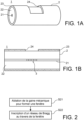
- the Figures 1A and 1B represent, in a perspective view and in a longitudinal sectional view, respectively, an example of a fiber optic sensor with a Bragg grating according to the invention. Only a section of the fiber optic sensor is shown in these figures.
- the fiber optic sensor 1 comprises an optical fiber 2 and a Bragg grating 3, visible in the Figure 1B .
- the optical fiber 2 comprises a core 21, an optical sheath 22 surrounding the core 21 and a mechanical sheath 23 surrounding the optical sheath 22.
- the optical fiber 2 is typically a single-mode optical fiber. Its dimensions are adapted to the transport of the optical signal used for the measurement by the Bragg grating 3.
- the core has for example a diameter less than or equal to 10 ⁇ m, the optical sheath a diameter between 80 ⁇ m and 150 ⁇ m and the optical sheath a diameter between 200 ⁇ m and 400 ⁇ m.
- the mechanical sheath 23 has the function of mechanically and/or chemically protecting the protective sheath. It may in particular comprise a material whose pyroscopic resistance is greater than or equal to a maximum operating temperature of the optical fiber sensor 1.
- the material of the protective sheath has, for example, a pyroscopic resistance greater than or equal to 350°C, preferably greater than or equal to 800°C. It may comprise a refractory material such as aluminum oxide or zirconium oxide. It may also comprise a metal such as aluminum, gold, copper, silver or nickel.
- the Bragg grating 3 is inscribed in the core 21. It is formed by a set of patterns whose refractive index differs from the refractive index of the core 21.
- the mechanical cladding 23 comprises an opening or window 24 extending radially over its entire thickness, that is to say between its internal surface, in contact with the optical cladding 22 and its external surface also forming the external surface of the optical fiber 2.
- the opening 24 is arranged to allow the passage of a laser beam for the inscription of the Bragg grating 3. Its dimensions are thus adapted both to the dimensions of the laser beam and to the dimensions of the Bragg grating.
- the opening 24 can extend longitudinally over a section of optical fiber, called a “cutting section", the length of which is greater than or equal to the length of the sensitive section.
- the opening 24 may extend circumferentially over a defined angular sector such that it has, by projection in a plane parallel to a longitudinal axis of the optical fiber, a width greater than or equal to the diameter of the core 21. Since the width of the patterns of the Bragg grating may be less than the diameter of the core 21, the opening 24 may have a projected width less than the diameter of the core and greater than or equal to the dimensions of the patterns of the Bragg grating.
- the angular sector defining the opening 24 may be between 0.5° and 120°.
- the Bragg grating optical fiber sensor according to the invention is suitable for both a point measurement of temperature and/or deformation and a distributed measurement.
- the optical fiber sensor comprises a plurality of openings arranged on different cutting sections of the optical fiber and a plurality of Bragg gratings inscribed on sensitive sections, each Bragg grating being associated with an opening.
- the optical fiber sensor is made from an optical fiber comprising a core, an optical cladding surrounding the core and a mechanical cladding surrounding the optical cladding.
- the optical fiber is typically a single-mode optical fiber.
- a first step S21 an opening or window is formed by ablation of the mechanical cladding. As indicated previously, the opening extends radially over the entire thickness of the mechanical cladding and extends axially over a cutting section long enough for the passage of a laser beam allowing the inscription of a Bragg grating.
- a Bragg grating is inscribed in the optical fiber through the opening.
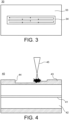
- FIG 3 illustrates an ablation of the mechanical sheath comprising a scan in a plane.
- an optical fiber 30 is shown in a top view. It comprises in particular a mechanical sheath 33 in which an opening 34 is formed.
- the scanning comprises a succession of four passes, each pass being carried out along an axis parallel to the longitudinal axis of the optical fiber.
- This scanning can be carried out optically, for example using a spatial light modulator or a galvanometric mirror associated with a focusing lens, or mechanically, by moving the laser or an optical element relative to the optical fiber.
- the scanning can be carried out along a single axis.
- the scanning can be carried out by translation and rotation about the longitudinal axis of the optical fiber.
- FIG 4 illustrates a particular embodiment in which the focal point of the laser beam is positioned upstream of the mechanical sheath.
- the optical fiber 40 is shown in a longitudinal sectional view.
- the optical fiber 40 comprises a core 41, an optical sheath 42 surrounding the core 41 and a mechanical sheath 43 surrounding the optical sheath 42.
- a laser beam 45 is applied to the surface of the mechanical sheath 43 so as to form an opening 44.
- a scan is necessary to form the opening 44.
- several pulses are necessary at each point of the opening in order to remove the material over the entire thickness of the mechanical sheath 43.
- the laser beam 45 is focused upstream of the outer surface of the mechanical sheath 43.
- this configuration ensures that the energy fluence in the optical sheath will be lower than the energy fluence in the mechanical sheath, even in the event of a shift in the focal point.
- Step S22 of registering a Bragg grating may comprise irradiating the core of the optical fiber with an ultraviolet laser beam.
- the core of the optical fiber must be photosensitive.
- the laser beam is focused in the vicinity of the core of the optical fiber, more preferably inside the heart.
- the laser beam can be continuous or pulsed. In the latter case, the pulse duration is for example between 5 ns and 500 ns.
- step S22 of writing a Bragg grating may comprise irradiating the core of the optical fiber with a femtosecond laser beam.
- the core of the optical fiber is then not necessarily photosensitive.
- the laser beam is focused in the vicinity of the core of the optical fiber, more preferably inside the core.
- the wavelength of the laser beam may be located in the wavelength range of infrared radiation, i.e. in the range from 700 nm to 1 mm.
- Writing the Bragg grating with a femtosecond laser has the advantage of being able to be carried out using the same laser source as that for ablation of the mechanical cladding.
Landscapes
- Physics & Mathematics (AREA)
- General Physics & Mathematics (AREA)
- Optics & Photonics (AREA)
- Engineering & Computer Science (AREA)
- Manufacturing & Machinery (AREA)
- Laser Beam Processing (AREA)
- Length Measuring Devices By Optical Means (AREA)
- Optical Transform (AREA)
- Measuring Temperature Or Quantity Of Heat (AREA)
- Optical Fibers, Optical Fiber Cores, And Optical Fiber Bundles (AREA)
Claims (14)
- Glasfasersensor mit Bragg-Spiegel, eine Glasfaser (2, 30, 40) umfassend, die einen Kern (21, 41) enthält, einen optischen Mantel (22, 42), der den Kern umgibt, und einen mechanischen Mantel (23, 33, 43), der den optischen Mantel umgibt, wobei der Glasfasersensor dadurch gekennzeichnet ist, dass der mechanische Mantel ein Metall umfasst, und eine Öffnung (24, 34, 44) umfasst, die so angeordnet ist, damit das Einschreiben von Mustern eines Bragg-Spiegels durch den Durchgang eines Laserstrahls durch die Öffnung (24, 34, 44) hindurch ermöglicht wird, wobei sich die Öffnung umlaufend erstreckt auf einem Winkelsektor und so definiert ist, dass sie, durch Projektion in einer Ebene parallel zu einer Längsachse der Glasfaser, eine Breite aufweist, die größer oder gleich dem Durchmesser des Kerns (21) ist und sich radial über seine gesamte Dicke erstreckt, und dass die Glasfaser einen Bragg-Spiegel (3) enthält, der im Kern im Bereich der Öffnung eingeschrieben ist.
- Glasfasersensor nach Anspruch 1, wobei die Öffnung (24, 34, 44), durch Projektion in einer Ebene parallel zu einer Längsachse der Glasfaser, eine Breite aufweist, die größer oder gleich einer entsprechenden Abmessung der Muster des Bragg-Spiegels (3) ist.
- Glasfasersensor nach einem der vorhergehenden Ansprüche, wobei sich die Öffnung (24, 34, 44) umlaufend erstreckt auf einem Winkelsektor, der zwischen 0,5 Grad und 120 Grad liegt.
- Glasfasersensor nach einem der vorhergehenden Ansprüche, wobei sich der Bragg-Spiegel (3) in Längsrichtung über einem Abschnitt der Glasfaser, "empfindlicher Abschnitt" genannt, erstreckt, und die Öffnung (24, 34, 44) sich in Längsrichtung über einem Abschnitt der Glasfaser, "Schneideabschnitt" genannt, erstreckt, wobei die Länge des Schneideabschnitts größer oder gleich der Länge des empfindlichen Abschnitts ist.
- Verfahren zur Herstellung eines Glasfasersensor mit Bragg-Spiegel ausgehend von einer Glasfaser (2, 30, 40), einen Kern (21, 41) enthaltend, einen optischen Mantel (22, 42), der den Kern umgibt, und einen mechanischen Mantel (23, 33, 43), der den optischen Mantel umgibt, wobei der mechanische Mantel ein Metall umfasst, wobei das Verfahren umfasst:- einen Schritt (S21) der Ablation des mechanischen Mantels (23, 33, 43) an einem Abschnitt der Glasfaser, "Schneideabschnitt" genannt, derart, dass eine Öffnung (24, 34, 44) gebildet wird, die sich umlaufend erstreckt auf einem Winkelsektor, und so definiert ist, dass sie, durch Projektion in einer Ebene parallel zu einer Längsachse der Glasfaser, eine Breite aufweist, die größer oder gleich dem Durchmesser des Kerns (21) ist und sich radial über die gesamte Dicke des mechanischen Mantels erstreckt, und- einen Schritt (S22) des Einschreibens eines Bragg-Spiegels (3) in die Glasfaser durch die Öffnung (24, 34, 44) hindurch,wobei der Ablationsschritt (S21) eine Insolation des mechanischen Mantels (23, 33, 43) durch einen in der Nähe des mechanischen Mantels fokussierten Laserstrahl (45) umfasst, wobei der Laserstrahl aus Femtosekundenimpulsen gebildet ist.
- Verfahren nach Anspruch 5, wobei der Ablationsschritt (S21) so konfiguriert ist, dass die Öffnung (24, 34, 44), durch Projektion in einer Ebene parallel zu einer Längsachse der Glasfaser, eine Breite aufweist, die größer oder gleich einer entsprechenden Abmessung der Muster des Bragg-Spiegels (3) ist.
- Verfahren nach einem der Ansprüche 5 und 6, wobei der Ablationsschritt (S21) so konfiguriert ist, dass sich die Öffnung (24, 34, 44) umlaufend erstreckt auf einem Winkelsektor, der zwischen 0,5 Grad und 120 Grad liegt, vorzugsweise zwischen 1 Grad und 10 Grad.
- Verfahren nach einem der Ansprüche 5 bis 7, wobei der Ablationsschritt (S21) ein Abtasten des Laserstrahls am mechanischen Mantel (23, 33, 43) umfasst.
- Verfahren nach einem der Ansprüche 5 bis 8, wobei der Ablationsschritt (S21) eine Insolation jedes Punktes des mechanischen Mantels (23, 33, 43) umfasst, der der Öffnung (24, 34, 44) entspricht, durch eine Vielzahl von Impulsen.
- Verfahren nach einem der Ansprüche 5 bis 9, wobei jeder Impuls des Laserstrahls eine Energiefluenz aufweist, die größer oder gleich einer Energiefluenzschwelle der Ablation des mechanischen Mantels (23, 33, 43) ist und kleiner oder gleich einer Energiefluenzschwelle der Ablation des optischen Mantels (22, 42).
- Verfahren nach einem der Ansprüche 5 bis 10, wobei ein Brennpunkt des Laserstrahls (45) stromaufwärts des mechanischen Mantels (23, 33, 43) positioniert ist.
- Glasfasersensor nach einem der Ansprüche 1 bis 4 oder dem Verfahren nach einem der Ansprüche 5 bis 11, wobei der mechanische Mantel (23, 33, 43) ein Material umfasst, dessen pyroskopischer Widerstand größer oder gleich 800 °C ist.
- Glasfasersensor nach einem der Ansprüche 1 bis 4 und 12 oder dem Verfahren nach einem der Ansprüche 5 bis 12, wobei der mechanische Mantel aus einem oder mehreren Metallen besteht.
- Glasfasersensor nach einem der Ansprüche 1 bis 4, 12 und 13 oder dem Verfahren nach einem der Ansprüche 5 bis 13, wobei der mechanische Mantel (23, 33, 43) eine Dicke zwischen 10 Mikrometer und 500 Mikrometer aufweist.
Applications Claiming Priority (2)
| Application Number | Priority Date | Filing Date | Title |
|---|---|---|---|
| FR1859499A FR3087257B1 (fr) | 2018-10-12 | 2018-10-12 | Capteur a fibre optique a reseau de bragg a haute tenue en temperature et son procede de fabrication |
| PCT/FR2019/052422 WO2020074843A1 (fr) | 2018-10-12 | 2019-10-11 | Capteur à fibre optique à réseau de bragg à haute tenue en température et son procédé de fabrication |
Publications (3)
| Publication Number | Publication Date |
|---|---|
| EP3864378A1 EP3864378A1 (de) | 2021-08-18 |
| EP3864378B1 true EP3864378B1 (de) | 2024-10-09 |
| EP3864378C0 EP3864378C0 (de) | 2024-10-09 |
Family
ID=67956808
Family Applications (1)
| Application Number | Title | Priority Date | Filing Date |
|---|---|---|---|
| EP19816827.0A Active EP3864378B1 (de) | 2018-10-12 | 2019-10-11 | Faseroptischer sensor mit bragg-gitter mit hoher temperaturstabilität und herstellungsverfahren dafür |
Country Status (5)
| Country | Link |
|---|---|
| US (1) | US11709078B2 (de) |
| EP (1) | EP3864378B1 (de) |
| ES (1) | ES2993560T3 (de) |
| FR (1) | FR3087257B1 (de) |
| WO (1) | WO2020074843A1 (de) |
Families Citing this family (7)
| Publication number | Priority date | Publication date | Assignee | Title |
|---|---|---|---|---|
| US11686900B2 (en) * | 2021-03-11 | 2023-06-27 | Taiwan Semiconductor Manufacturing Company, Ltd. | Semiconductor package, optical device and method of fabricating the same |
| US11946814B2 (en) * | 2021-06-10 | 2024-04-02 | Toyota Motor Engineering & Manufacturing North America, Inc. | Window-based temperature determination and/or display |
| US12092529B2 (en) * | 2021-11-29 | 2024-09-17 | Toyota Motor Engineering & Manufacturing North America, Inc. | Window-based object detection and/or identification |
| US11965374B2 (en) * | 2021-11-29 | 2024-04-23 | Toyota Motor Engineering & Manufacturing North America, Inc. | Anti-pinching window |
| CN115031649B (zh) * | 2022-05-16 | 2025-02-21 | 北京天骥空间科技有限公司 | 基于纤芯折射率类线性分布的超高分辨率弯曲温度传感器 |
| KR20250031456A (ko) * | 2023-08-28 | 2025-03-07 | 한국과학기술원 | 온도와 변형률의 동시 계측이 가능한 이중 모드 동축 섬유형 센서, 그 제조 방법 및 계측 시스템 |
| CN117406335B (zh) * | 2023-10-18 | 2025-07-22 | 湖北特种设备检验检测研究院 | 一种光纤光栅氢气传感器及其制备方法 |
Citations (1)
| Publication number | Priority date | Publication date | Assignee | Title |
|---|---|---|---|---|
| US5101090A (en) * | 1990-11-19 | 1992-03-31 | At&T Bell Laboratories | Methods and apparatus for making optical fiber couplers |
Family Cites Families (4)
| Publication number | Priority date | Publication date | Assignee | Title |
|---|---|---|---|---|
| US6272886B1 (en) * | 1996-10-23 | 2001-08-14 | 3M Innovative Properties Company | Incremental method of producing multiple UV-induced gratings on a single optical fiber |
| EP2934304B1 (de) * | 2012-12-21 | 2021-10-13 | Philips Image Guided Therapy Corporation | Multisensorvorrichtungen |
| RU2704067C2 (ru) * | 2014-09-17 | 2019-10-23 | Афл Телекомьюникейшнс Ллс | Способ и устройство для производства оптического волокна с металлическим покрытием и полученное оптическое волокно |
| FR3087008B1 (fr) * | 2018-10-08 | 2021-01-01 | Commissariat Energie Atomique | Capteur de temperature a reseau de bragg insensible aux deformations |
-
2018
- 2018-10-12 FR FR1859499A patent/FR3087257B1/fr active Active
-
2019
- 2019-10-11 EP EP19816827.0A patent/EP3864378B1/de active Active
- 2019-10-11 US US17/284,196 patent/US11709078B2/en active Active
- 2019-10-11 WO PCT/FR2019/052422 patent/WO2020074843A1/fr not_active Ceased
- 2019-10-11 ES ES19816827T patent/ES2993560T3/es active Active
Patent Citations (1)
| Publication number | Priority date | Publication date | Assignee | Title |
|---|---|---|---|---|
| US5101090A (en) * | 1990-11-19 | 1992-03-31 | At&T Bell Laboratories | Methods and apparatus for making optical fiber couplers |
Also Published As
| Publication number | Publication date |
|---|---|
| WO2020074843A1 (fr) | 2020-04-16 |
| EP3864378A1 (de) | 2021-08-18 |
| US11709078B2 (en) | 2023-07-25 |
| ES2993560T3 (en) | 2025-01-02 |
| US20210341314A1 (en) | 2021-11-04 |
| EP3864378C0 (de) | 2024-10-09 |
| FR3087257B1 (fr) | 2024-07-26 |
| FR3087257A1 (fr) | 2020-04-17 |
Similar Documents
| Publication | Publication Date | Title |
|---|---|---|
| EP3864378B1 (de) | Faseroptischer sensor mit bragg-gitter mit hoher temperaturstabilität und herstellungsverfahren dafür | |
| EP3844466B1 (de) | Deformationsunempfindlicher bragg-gitter-temperatursensor | |
| WO2019243745A1 (fr) | Capteur à fibre optique à réseau de bragg associé à une structure diffusante et procédés de localisation et d'installation d'un tel capteur | |
| FR2674639A1 (fr) | Fibre optique a reseau de bragg et ses applications. | |
| EP2518545A1 (de) | Lichtübertragungsvorrichtung und Verfahren | |
| EP3853655B1 (de) | Vorrichtungen und verfahren zum transportieren und steuern von lichtstrahlen | |
| CA2504765C (en) | Optical fiber sensor based on retro-reflective fiber bragg gratings | |
| Chernikov et al. | Line-by-line fiber Bragg grating fabrication by femtosecond laser radiation | |
| EP0464568B1 (de) | Verfahren zur Herstellung einer optischen Faser, insbesondere bestimmt für die Zeitbereichsreflektometrie | |
| EP1910805A1 (de) | Optisches refraktometer zur messung des salzgehalts vonmeerwasser und entsprechender salzgehaltsensor | |
| US20210318488A1 (en) | Phase-shifted fiber bragg grating sensor and method for producing same | |
| Fiorin et al. | FBG-assisted micro-channel for refractive index measurements | |
| FR2901608A1 (fr) | Systeme de mesure et de detection de parametres et d'anomalies | |
| WO2010094865A1 (fr) | Procede de realisation d'un defaut a la surface d'une fibre optique | |
| EP3489629A1 (de) | Vorrichtung zur kartografischen erfassung der temperatur und deformation einer struktur, insbesondere einer wand eines nuklearen brennstabs | |
| WO2015091502A1 (fr) | Procédé de fabrication d'une fibre optique traitée pour capteur de température résistant aux radiations | |
| EP1856486B1 (de) | Faseroptischer mehrfachmodus-stosssensor, der gemäss dem prinzip der kopplung zwischen fasergeführten modenführungen arbeitet | |
| EP0542603A1 (de) | Faseroptischer Sensor zur Erfassung eines Parameters, Verfahren zum Auswerten eines solchen Parameters, und Verwendung des Sensors zur Gasmessung | |
| Chen et al. | Fabrication of the novel multi-D-shape fiber sensor by femtosecond laser machining with the diffractive optical element | |
| Baklanov et al. | Optical Reliability and Reliability of Optical Devices | |
| Liang et al. | Femtosecond laser induced refractive index structures in polymer optical fibre (POF) for sensing | |
| CA3028870C (fr) | Procede d'inspection d'une surface metallique et dispositif associe | |
| EP4630762A1 (de) | Vorrichtung zur messung einer physikalischen grösse unter verwendung des optischen vernier-effekts | |
| EP4562460A1 (de) | Optische faser mit einem bragg-gitter | |
| WO2024094581A1 (fr) | Coupleur à fibre creuse à double gaine et procédé de fabrication d'un tel coupleur |
Legal Events
| Date | Code | Title | Description |
|---|---|---|---|
| STAA | Information on the status of an ep patent application or granted ep patent |
Free format text: STATUS: UNKNOWN |
|
| STAA | Information on the status of an ep patent application or granted ep patent |
Free format text: STATUS: THE INTERNATIONAL PUBLICATION HAS BEEN MADE |
|
| PUAI | Public reference made under article 153(3) epc to a published international application that has entered the european phase |
Free format text: ORIGINAL CODE: 0009012 |
|
| STAA | Information on the status of an ep patent application or granted ep patent |
Free format text: STATUS: REQUEST FOR EXAMINATION WAS MADE |
|
| 17P | Request for examination filed |
Effective date: 20210413 |
|
| AK | Designated contracting states |
Kind code of ref document: A1 Designated state(s): AL AT BE BG CH CY CZ DE DK EE ES FI FR GB GR HR HU IE IS IT LI LT LU LV MC MK MT NL NO PL PT RO RS SE SI SK SM TR |
|
| DAV | Request for validation of the european patent (deleted) | ||
| DAX | Request for extension of the european patent (deleted) | ||
| STAA | Information on the status of an ep patent application or granted ep patent |
Free format text: STATUS: EXAMINATION IS IN PROGRESS |
|
| 17Q | First examination report despatched |
Effective date: 20230217 |
|
| GRAP | Despatch of communication of intention to grant a patent |
Free format text: ORIGINAL CODE: EPIDOSNIGR1 |
|
| STAA | Information on the status of an ep patent application or granted ep patent |
Free format text: STATUS: GRANT OF PATENT IS INTENDED |
|
| INTG | Intention to grant announced |
Effective date: 20240102 |
|
| GRAJ | Information related to disapproval of communication of intention to grant by the applicant or resumption of examination proceedings by the epo deleted |
Free format text: ORIGINAL CODE: EPIDOSDIGR1 |
|
| STAA | Information on the status of an ep patent application or granted ep patent |
Free format text: STATUS: EXAMINATION IS IN PROGRESS |
|
| GRAP | Despatch of communication of intention to grant a patent |
Free format text: ORIGINAL CODE: EPIDOSNIGR1 |
|
| STAA | Information on the status of an ep patent application or granted ep patent |
Free format text: STATUS: GRANT OF PATENT IS INTENDED |
|
| INTC | Intention to grant announced (deleted) | ||
| INTG | Intention to grant announced |
Effective date: 20240513 |
|
| GRAS | Grant fee paid |
Free format text: ORIGINAL CODE: EPIDOSNIGR3 |
|
| GRAA | (expected) grant |
Free format text: ORIGINAL CODE: 0009210 |
|
| STAA | Information on the status of an ep patent application or granted ep patent |
Free format text: STATUS: THE PATENT HAS BEEN GRANTED |
|
| AK | Designated contracting states |
Kind code of ref document: B1 Designated state(s): AL AT BE BG CH CY CZ DE DK EE ES FI FR GB GR HR HU IE IS IT LI LT LU LV MC MK MT NL NO PL PT RO RS SE SI SK SM TR |
|
| REG | Reference to a national code |
Ref country code: CH Ref legal event code: EP |
|
| RAP4 | Party data changed (patent owner data changed or rights of a patent transferred) |
Owner name: COMMISSARIAT A L'ENERGIE ATOMIQUE ET AUX ENERGIESALTERNATIVES |
|
| REG | Reference to a national code |
Ref country code: DE Ref legal event code: R096 Ref document number: 602019060177 Country of ref document: DE |
|
| REG | Reference to a national code |
Ref country code: IE Ref legal event code: FG4D Free format text: LANGUAGE OF EP DOCUMENT: FRENCH |
|
| U01 | Request for unitary effect filed |
Effective date: 20241031 |
|
| U07 | Unitary effect registered |
Designated state(s): AT BE BG DE DK EE FI FR IT LT LU LV MT NL PT RO SE SI Effective date: 20241112 |
|
| REG | Reference to a national code |
Ref country code: ES Ref legal event code: FG2A Ref document number: 2993560 Country of ref document: ES Kind code of ref document: T3 Effective date: 20250102 |
|
| U20 | Renewal fee for the european patent with unitary effect paid |
Year of fee payment: 6 Effective date: 20250130 |
|
| PG25 | Lapsed in a contracting state [announced via postgrant information from national office to epo] |
Ref country code: IS Free format text: LAPSE BECAUSE OF FAILURE TO SUBMIT A TRANSLATION OF THE DESCRIPTION OR TO PAY THE FEE WITHIN THE PRESCRIBED TIME-LIMIT Effective date: 20250209 Ref country code: HR Free format text: LAPSE BECAUSE OF FAILURE TO SUBMIT A TRANSLATION OF THE DESCRIPTION OR TO PAY THE FEE WITHIN THE PRESCRIBED TIME-LIMIT Effective date: 20241009 |
|
| PG25 | Lapsed in a contracting state [announced via postgrant information from national office to epo] |
Ref country code: NO Free format text: LAPSE BECAUSE OF FAILURE TO SUBMIT A TRANSLATION OF THE DESCRIPTION OR TO PAY THE FEE WITHIN THE PRESCRIBED TIME-LIMIT Effective date: 20250109 |
|
| PG25 | Lapsed in a contracting state [announced via postgrant information from national office to epo] |
Ref country code: GR Free format text: LAPSE BECAUSE OF FAILURE TO SUBMIT A TRANSLATION OF THE DESCRIPTION OR TO PAY THE FEE WITHIN THE PRESCRIBED TIME-LIMIT Effective date: 20250110 |
|
| PG25 | Lapsed in a contracting state [announced via postgrant information from national office to epo] |
Ref country code: PL Free format text: LAPSE BECAUSE OF FAILURE TO SUBMIT A TRANSLATION OF THE DESCRIPTION OR TO PAY THE FEE WITHIN THE PRESCRIBED TIME-LIMIT Effective date: 20241009 |
|
| PG25 | Lapsed in a contracting state [announced via postgrant information from national office to epo] |
Ref country code: RS Free format text: LAPSE BECAUSE OF FAILURE TO SUBMIT A TRANSLATION OF THE DESCRIPTION OR TO PAY THE FEE WITHIN THE PRESCRIBED TIME-LIMIT Effective date: 20250109 |
|
| REG | Reference to a national code |
Ref country code: CH Ref legal event code: PL |
|
| PG25 | Lapsed in a contracting state [announced via postgrant information from national office to epo] |
Ref country code: SM Free format text: LAPSE BECAUSE OF FAILURE TO SUBMIT A TRANSLATION OF THE DESCRIPTION OR TO PAY THE FEE WITHIN THE PRESCRIBED TIME-LIMIT Effective date: 20241009 |
|
| PG25 | Lapsed in a contracting state [announced via postgrant information from national office to epo] |
Ref country code: MC Free format text: LAPSE BECAUSE OF FAILURE TO SUBMIT A TRANSLATION OF THE DESCRIPTION OR TO PAY THE FEE WITHIN THE PRESCRIBED TIME-LIMIT Effective date: 20241009 |
|
| PG25 | Lapsed in a contracting state [announced via postgrant information from national office to epo] |
Ref country code: CH Free format text: LAPSE BECAUSE OF NON-PAYMENT OF DUE FEES Effective date: 20241031 |
|
| PG25 | Lapsed in a contracting state [announced via postgrant information from national office to epo] |
Ref country code: SK Free format text: LAPSE BECAUSE OF FAILURE TO SUBMIT A TRANSLATION OF THE DESCRIPTION OR TO PAY THE FEE WITHIN THE PRESCRIBED TIME-LIMIT Effective date: 20241009 |
|
| PG25 | Lapsed in a contracting state [announced via postgrant information from national office to epo] |
Ref country code: CZ Free format text: LAPSE BECAUSE OF FAILURE TO SUBMIT A TRANSLATION OF THE DESCRIPTION OR TO PAY THE FEE WITHIN THE PRESCRIBED TIME-LIMIT Effective date: 20241009 |
|
| PLBE | No opposition filed within time limit |
Free format text: ORIGINAL CODE: 0009261 |
|
| STAA | Information on the status of an ep patent application or granted ep patent |
Free format text: STATUS: NO OPPOSITION FILED WITHIN TIME LIMIT |
|
| 26N | No opposition filed |
Effective date: 20250710 |
|
| GBPC | Gb: european patent ceased through non-payment of renewal fee |
Effective date: 20250109 |
|
| PG25 | Lapsed in a contracting state [announced via postgrant information from national office to epo] |
Ref country code: GB Free format text: LAPSE BECAUSE OF NON-PAYMENT OF DUE FEES Effective date: 20250109 |
|
| PG25 | Lapsed in a contracting state [announced via postgrant information from national office to epo] |
Ref country code: IE Free format text: LAPSE BECAUSE OF NON-PAYMENT OF DUE FEES Effective date: 20241011 |
|
| U1N | Appointed representative for the unitary patent procedure changed after the registration of the unitary effect |
Representative=s name: SANTARELLI; FR |
|
| U20 | Renewal fee for the european patent with unitary effect paid |
Year of fee payment: 7 Effective date: 20251022 |
|
| PG25 | Lapsed in a contracting state [announced via postgrant information from national office to epo] |
Ref country code: CY Free format text: LAPSE BECAUSE OF FAILURE TO SUBMIT A TRANSLATION OF THE DESCRIPTION OR TO PAY THE FEE WITHIN THE PRESCRIBED TIME-LIMIT; INVALID AB INITIO Effective date: 20191011 |
|
| PGFP | Annual fee paid to national office [announced via postgrant information from national office to epo] |
Ref country code: ES Payment date: 20251114 Year of fee payment: 7 |
|
| PG25 | Lapsed in a contracting state [announced via postgrant information from national office to epo] |
Ref country code: HU Free format text: LAPSE BECAUSE OF FAILURE TO SUBMIT A TRANSLATION OF THE DESCRIPTION OR TO PAY THE FEE WITHIN THE PRESCRIBED TIME-LIMIT; INVALID AB INITIO Effective date: 20191011 |