EP3864332B1 - Anschlussanordnung - Google Patents
Anschlussanordnung Download PDFInfo
- Publication number
- EP3864332B1 EP3864332B1 EP19750163.8A EP19750163A EP3864332B1 EP 3864332 B1 EP3864332 B1 EP 3864332B1 EP 19750163 A EP19750163 A EP 19750163A EP 3864332 B1 EP3864332 B1 EP 3864332B1
- Authority
- EP
- European Patent Office
- Prior art keywords
- clamp
- cover
- bracket
- collar
- elongate member
- Prior art date
- Legal status (The legal status is an assumption and is not a legal conclusion. Google has not performed a legal analysis and makes no representation as to the accuracy of the status listed.)
- Active
Links
Images


Classifications
-
- F—MECHANICAL ENGINEERING; LIGHTING; HEATING; WEAPONS; BLASTING
- F16—ENGINEERING ELEMENTS AND UNITS; GENERAL MEASURES FOR PRODUCING AND MAINTAINING EFFECTIVE FUNCTIONING OF MACHINES OR INSTALLATIONS; THERMAL INSULATION IN GENERAL
- F16L—PIPES; JOINTS OR FITTINGS FOR PIPES; SUPPORTS FOR PIPES, CABLES OR PROTECTIVE TUBING; MEANS FOR THERMAL INSULATION IN GENERAL
- F16L3/00—Supports for pipes, cables or protective tubing, e.g. hangers, holders, clamps, cleats, clips, brackets
- F16L3/24—Supports for pipes, cables or protective tubing, e.g. hangers, holders, clamps, cleats, clips, brackets with special member for attachment to profiled girders
- F16L3/243—Supports for pipes, cables or protective tubing, e.g. hangers, holders, clamps, cleats, clips, brackets with special member for attachment to profiled girders the special member being inserted in the profiled girder
-
- A—HUMAN NECESSITIES
- A47—FURNITURE; DOMESTIC ARTICLES OR APPLIANCES; COFFEE MILLS; SPICE MILLS; SUCTION CLEANERS IN GENERAL
- A47K—SANITARY EQUIPMENT; ACCESSORIES THEREFOR, e.g. TOILET ACCESSORIES
- A47K17/00—Other sanitary equipment not covered by the other groups of this subclass ; Holders for toilet brushes
- A47K17/02—Body supports, other than seats, for closets, e.g. handles, back-rests, foot-rests; Accessories for closets, e.g. reading tables
- A47K17/022—Wall mounted grab bars or handles, with or without support on the floor
-
- A—HUMAN NECESSITIES
- A47—FURNITURE; DOMESTIC ARTICLES OR APPLIANCES; COFFEE MILLS; SPICE MILLS; SUCTION CLEANERS IN GENERAL
- A47K—SANITARY EQUIPMENT; ACCESSORIES THEREFOR, e.g. TOILET ACCESSORIES
- A47K3/00—Baths; Showers; Appurtenances therefor
- A47K3/001—Accessories for baths, not provided for in other subgroups of group A47K3/00; Insertions, e.g. for babies; Tubs suspended or inserted in baths; Security or alarm devices; Protecting linings or coverings; Devices for cleaning or disinfecting baths; Bath insulation
- A47K3/003—Grips for baths
-
- E—FIXED CONSTRUCTIONS
- E04—BUILDING
- E04F—FINISHING WORK ON BUILDINGS, e.g. STAIRS, FLOORS
- E04F11/00—Stairways, ramps, or like structures; Balustrades; Handrails
- E04F11/18—Balustrades; Handrails
- E04F11/1802—Handrails mounted on walls, e.g. on the wall side of stairs
- E04F11/1804—Details of anchoring to the wall
-
- F—MECHANICAL ENGINEERING; LIGHTING; HEATING; WEAPONS; BLASTING
- F16—ENGINEERING ELEMENTS AND UNITS; GENERAL MEASURES FOR PRODUCING AND MAINTAINING EFFECTIVE FUNCTIONING OF MACHINES OR INSTALLATIONS; THERMAL INSULATION IN GENERAL
- F16M—FRAMES, CASINGS OR BEDS OF ENGINES, MACHINES OR APPARATUS, NOT SPECIFIC TO ENGINES, MACHINES OR APPARATUS PROVIDED FOR ELSEWHERE; STANDS; SUPPORTS
- F16M13/00—Other supports for positioning apparatus or articles; Means for steadying hand-held apparatus or articles
- F16M13/02—Other supports for positioning apparatus or articles; Means for steadying hand-held apparatus or articles for supporting on, or attaching to, an object, e.g. tree, gate, window-frame, cycle
- F16M13/022—Other supports for positioning apparatus or articles; Means for steadying hand-held apparatus or articles for supporting on, or attaching to, an object, e.g. tree, gate, window-frame, cycle repositionable
-
- A—HUMAN NECESSITIES
- A47—FURNITURE; DOMESTIC ARTICLES OR APPLIANCES; COFFEE MILLS; SPICE MILLS; SUCTION CLEANERS IN GENERAL
- A47K—SANITARY EQUIPMENT; ACCESSORIES THEREFOR, e.g. TOILET ACCESSORIES
- A47K10/00—Body-drying implements; Toilet paper; Holders therefor
- A47K10/04—Towel racks; Towel rails; Towel rods; Towel rolls, e.g. rotatable
-
- A—HUMAN NECESSITIES
- A47—FURNITURE; DOMESTIC ARTICLES OR APPLIANCES; COFFEE MILLS; SPICE MILLS; SUCTION CLEANERS IN GENERAL
- A47K—SANITARY EQUIPMENT; ACCESSORIES THEREFOR, e.g. TOILET ACCESSORIES
- A47K2201/00—Details of connections of bathroom accessories, e.g. fixing soap or towel holder to a wall
- A47K2201/02—Connections to a wall mounted support
-
- A—HUMAN NECESSITIES
- A47—FURNITURE; DOMESTIC ARTICLES OR APPLIANCES; COFFEE MILLS; SPICE MILLS; SUCTION CLEANERS IN GENERAL
- A47K—SANITARY EQUIPMENT; ACCESSORIES THEREFOR, e.g. TOILET ACCESSORIES
- A47K3/00—Baths; Showers; Appurtenances therefor
- A47K3/28—Showers or bathing douches
- A47K3/281—Accessories for showers or bathing douches, e.g. cleaning devices for walls or floors of showers
-
- E—FIXED CONSTRUCTIONS
- E03—WATER SUPPLY; SEWERAGE
- E03C—DOMESTIC PLUMBING INSTALLATIONS FOR FRESH WATER OR WASTE WATER; SINKS
- E03C1/00—Domestic plumbing installations for fresh water or waste water; Sinks
- E03C1/02—Plumbing installations for fresh water
- E03C1/06—Devices for suspending or supporting the supply pipe or supply hose of a shower-bath
-
- F—MECHANICAL ENGINEERING; LIGHTING; HEATING; WEAPONS; BLASTING
- F16—ENGINEERING ELEMENTS AND UNITS; GENERAL MEASURES FOR PRODUCING AND MAINTAINING EFFECTIVE FUNCTIONING OF MACHINES OR INSTALLATIONS; THERMAL INSULATION IN GENERAL
- F16B—DEVICES FOR FASTENING OR SECURING CONSTRUCTIONAL ELEMENTS OR MACHINE PARTS TOGETHER, e.g. NAILS, BOLTS, CIRCLIPS, CLAMPS, CLIPS OR WEDGES; JOINTS OR JOINTING
- F16B9/00—Connections of rods or tubular parts to flat surfaces at an angle
- F16B9/05—Connections of rods or tubular parts to flat surfaces at an angle by way of an intermediate member
-
- F—MECHANICAL ENGINEERING; LIGHTING; HEATING; WEAPONS; BLASTING
- F16—ENGINEERING ELEMENTS AND UNITS; GENERAL MEASURES FOR PRODUCING AND MAINTAINING EFFECTIVE FUNCTIONING OF MACHINES OR INSTALLATIONS; THERMAL INSULATION IN GENERAL
- F16L—PIPES; JOINTS OR FITTINGS FOR PIPES; SUPPORTS FOR PIPES, CABLES OR PROTECTIVE TUBING; MEANS FOR THERMAL INSULATION IN GENERAL
- F16L3/00—Supports for pipes, cables or protective tubing, e.g. hangers, holders, clamps, cleats, clips, brackets
- F16L3/08—Supports for pipes, cables or protective tubing, e.g. hangers, holders, clamps, cleats, clips, brackets substantially surrounding the pipe, cable or protective tubing
- F16L3/12—Supports for pipes, cables or protective tubing, e.g. hangers, holders, clamps, cleats, clips, brackets substantially surrounding the pipe, cable or protective tubing comprising a member substantially surrounding the pipe, cable or protective tubing
Definitions
- the present disclosure relates to a fitting assembly, and in particular a fitting assembly for attaching an elongate member, such as a rail, tube, or pipe to a surface, such as a wall, within or in the vicinity of a shower area.
- an elongate member such as a rail, tube, or pipe
- a surface such as a wall
- CN207285980 discloses a fixing mechanism for a shower, comprising a first body for fixing on a wall and a second body for connecting and fixing the shower.
- the second body is detachably connected with the first body.
- the first body includes a first wall and a second wall vertically arranged, the second wall is fixedly connected to one side of the first wall, and the surface of at least one side of the second wall protrudes to form a T-shaped first protrusion.
- the first protrusion extends from the end edge of the second wall to the first wall, and the upper and lower sides of the first protrusion respectively form a first groove and a second groove.
- the second body includes a sleeve for inserting and connecting the shower pipe of the shower.
- the outer surface of the sleeve protrudes outward to form at least one third wall.
- the third wall is provided with a notch, and the notch is formed by the third wall.
- the end edge of the third wall extends to the outer surface of the sleeve, and the third wall is located at the top and bottom of the notch and is respectively provided with a first strip block matched with the first groove and a second strip matched with the second groove.
- CN206342393 discloses an adjustable mounting seat for a shower rod, which includes an attachment seat fixed to a wall by a locking structure, an adjusting member, and a connecting sleeve.
- the connecting sleeve is on the adjusting member.
- the locking structure is integrated with the attachment seat.
- the adjusting member is connected with the attachment seat through an adjustable structure.
- the adjustable structure includes an adjusting hole, a connecting hole, and an adjusting element.
- the adjusting hole is opened on the mounting seat and arranged along the direction perpendicular to the wall.
- the connecting hole is formed on the adjusting member.
- the adjusting member is inserted into the mounting seat and is displaced along the direction perpendicular to the wall.
- the adjusting element is passed through the connecting hole and the adjusting hole, so that the adjusting member and the mounting seat form an adjustable fit.
- GB 1556730 discloses a post for supporting a rail.
- the post comprises a collar member for carrying a rail and having a depending leg, and a post member, with complementary interlocking arrangements on the leg of the collar member and on the post member respectively, the complementary interlocking arrangements comprising a resilient lug angled out of the surface of one member and a recess in the other member shaped to receive the lug, such that the interlocking arrangements are engageable by a snap fit when one of the two members is inserted into the other and are releasable upon rotation of one of the two members relative to the other.
- US6257530 discloses a clasping device for clasping a longitudinal object.
- the device includes a clasping member having a chamber for receiving the object and having one or more blades extended inward of the chamber of the clasping member for engaging with and for clasping the object in the clasping member when the ends of the clasping member are forced toward each other.
- the blade includes a cusp and/or a tip for clasping the object in the clasping member. The ends of the clasping member are engaged into a socket orifice of a bracket for forcing the blades to engage with the object.
- EP1529996 discloses a pipe-holding device for fixing a pipe on a surface.
- the device comprises a fixing part for attaching to the surface, and a pipe-holding part that is connected to the fixing part by a clip mechanism. Also disclosed is a tool for releasing the clip mechanism of a pipe-holding device; and a process for fixing a pipe on a surface.
- the fixing part preferably has at least one lateral opening for introducing a tool for releasing the clip mechanism.
- a first aspect provides a fitting assembly for attaching an elongate member to a surface within a shower or bath area, the fitting assembly comprising:
- the elongate member such as a rail or pipe
- the collar tightens around the elongate member as a result of the finger being urged by the receiving portion of the bracket in a manner so as to close or reduce the split in the collar - thereby tightening the collar around the elongate member. Therefore, in one single movement the cover is secured onto the bracket, which is mounted to the surface, and the elongate member is secured in the collar which is itself retained inside the cover. This results in the elongate member being secured to the surface, such as a wall of a shower or bath area.
- the clamp may comprise a pair of opposing fingers extending outward from the collar adjacent either side of the split.
- the receiving portion of the bracket may be arranged to urge the opposing fingers towards each other thereby compressing the collar portion at the split and clamping the elongate member within the collar when the cover containing the clamp is engaged with the bracket.
- the clamp may be more stable in operation because lateral forces arising within the fitting assembly are inherently balanced. Further, this gives rise to a plane of symmetry in the fitting assembly which may provide advantages such as simplified manufacturing or assembly of the fitting assembly.
- the opposing fingers may extend approximately parallel to each other. There may be a separation, typically a small separation, between the opposing fingers as dictated by the split.
- the receiving portion of the bracket may comprise one or more ribs. Ribs are well suited to abutting against the finger or pair of opposing fingers so as to tighten the collar around the elongate member.
- the ribs may be formed with a smooth, graded inclined surface so as to gently urge the fingers together (or the single finger to one side) as the cover containing the clamp is slid onto the bracket. In this manner a smooth insertion force of the cover containing the clamp onto the bracket may be allowed for, rather than a sudden snap fit.
- the bracket may comprise one or more locking tabs arranged to engage with one or more corresponding notches provided on the cover, thereby locking the cover and the bracket together when the cover containing the clamp is engaged with the bracket. In this manner, once the cover containing the clamp has been pushed far enough onto the bracket that the notches align with the tabs the whole assembly may be locked together. This may prevent the assembly being unintentionally disassembled, and/or the elongate member being accidentally released, unless the tabs are deliberately depressed to enable the cover containing the clamp to be slid off the bracket.
- the cover may comprise one or more projections or recesses located on opposing interior surfaces of the cover, which may be arranged to engage with one or more corresponding recesses/openings or projections of the clamp with a snap fit to thereby retain the clamp securely within the cover.
- the clamp can be provided as a separate part which may be quickly and easily secured inside the cover and removed if required at a later stage, e.g. to replace the clamp.
- This also enables different sized clamps (e.g. collars having different radii in embodiments where the collar has a circular cross section) to be provided with a single cover and bracket and assembled in situ to suit a range of different elongate member radii.
- the bracket may be arranged to be fixed to the surface by means of one or more mechanical fasteners, e.g. screws. In this manner the bracket may be secured to the surface, e.g. a wall of a shower area.
- the bracket may be adapted to be affixed to the surface by other means, such as adhesive pads, glue or a suction mount, which may be arranged for example to fix the bracket onto a surface such as shower enclosure or cubicle wall, glass screen, or mirror thereof.
- the elongate member may be a pipe, such as a riser pipe, or a rail, such as a towel rail, an ornamental or decorative rail or a guide rail (e.g. a hand rail) to aid support for a user of the shower.
- a pipe such as a riser pipe
- a rail such as a towel rail, an ornamental or decorative rail or a guide rail (e.g. a hand rail) to aid support for a user of the shower.
- This fitting assembly may be modular in nature.
- the one or more fingers of the clamp may comprise one or more outwardly facing recessed slots arranged to interlock with the receiving portion of the bracket. This may help to increase the load bearing capability of the fitting assembly once assembled.
- a second aspect provides a kit of parts arranged to be assembled to form a fitting assembly according to the first aspect.
- the kit of parts may comprise the fitting assembly according to the first aspect, a means for fixing the bracket of the fitting assembly to a surface and an elongate member.
- Said means for fixing the bracket of the fitting assembly to a surface may include a mechanical fastener such as a screw, an adhesive pad or a suction mount.
- a third aspect provides a shower or bath area comprising an elongate member supported by one or more fitting assemblies according to the first aspect.
- the shower or bath area may comprise a shower cubicle, a shower enclosure and/or a bathtub.
- One or more ablutionary fittings may be provided in the shower or bath area.
- a fourth aspect provides a method of attaching an elongate member to a surface within a shower or bath area, the method comprising:
- the collar tightens around the elongate member because when the cover containing the clamp is installed/slid onto the bracket, the one or more fingers of the clamp are urged by means of the receiving portion of the bracket so as to reduce or close the split in the collar, thereby securing the collar around the elongate member and effectively clamping the elongate member.
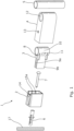
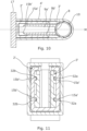
- the fitting assembly 1 comprises a bracket 2, a clamp 3 and a cover 4.
- the fitting assembly is suitable for attaching an elongate member 5, such as a pipe or rail, to a surface 17 within a bathroom, such as a wall of a shower area.
- the bracket 2 is fixed to the surface 17 using, for example, a wall plug 6 and screw 7, although other means are also envisaged such as adhesive pads or suction mounts and the like.
- the clamp 3 comprises a collar 10 which is arranged to receive and secure around the elongate member 5.
- the collar 10 has an axially-extending split 8 along the length of one side of the collar 10.
- the split 8 may run the full length of the collar 10 or only part of the length, e.g. 80% or 90% thereof.
- the clamp 3 also has a pair of opposing fingers 9a and 9b extending radially outward from the collar 10 adjacent either side of the split 8. In the absence of any inward force being applied to the fingers 9a and 9b, the collar 10 is loose enough to permit the elongate member 5 to be slid into the collar 10 in the axial direction without the elongate member encountering significant resistance, e.g. it may only be held loosely in the collar 10 at first.
- the elongate member 5 can be clamped tightly in place by imparting an inward force onto the two fingers 9a and 9b, in order to urge the fingers 9a and 9b together thereby substantially closing the split 8 and clamping the collar 10 tightly around the elongate member 5 by effectively reducing the radius of the collar 10 slightly at the split 8. In this manner the elongate member 5 is held in the collar 10 of the clamp 3 by friction, i.e. an interference fit is achieved.
- the clamp 3 has a pair of diametrically opposed openings or recesses 11 in walls of the collar 10 which are arranged to engage with corresponding projections 34 provided on opposing interior surfaces of the cover 4.
- the clamp 3 is secured and retained in place inside the cover 4 by means of a snap fit between openings 11 of the clamp 3 and the projections 34 of the cover 4. In this manner the clamp 3 is manufactured as a separate component and then subsequently assembled into the cover 4 either by the end user or by the manufacturer.
- the collar 10 of the clamp 3 is axially aligned with a through aperture 12 of the cover 4 such that the elongate member 5 can be slid through the aperture 12 of the cover 4 and the collar 10 of the clamp 3 in one movement.
- the elongate member 5 may extend outwards from either side of the cover 4, e.g. if the fitting assembly 1 is being provided at an intermediate/midway position on the elongate member 5.
- the elongate member 5 may terminate inside the cover 4 at an axial position just past the collar 10, e.g. if the fitting assembly 1 is being provided at an end position of the elongate member 5.
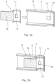
- the cover 4 containing the clamp 3 fixed inside and having the elongate member 5 inserted therein is then installed onto the bracket 2 which is itself secured to the surface 17 in the manner described herein.
- the bracket 2 has a receiving portion comprising internal ribs 15a and 15b on opposing interior surfaces which are arranged to urge the fingers 9a and 9b respectively of the clamp 3 inwards towards each other so as to compress the collar portion 10 at the split 8, thereby clamping the elongate member 5 securely within the collar 10.
- the cover 4 slides over the bracket 2 such that the bracket 2 is not visible once the fitting assembly 1 is assembled.
- An outwardly-facing locking tab 14 on the bracket 2 engages a corresponding notch 13 on the cover 4 when the cover 4 is slid onto the bracket 2.
- Figures 5a and 5b show the complete fitting assembly 1 when it is attaching the elongate member 5 to a wall 17.
- the fitting assembly generally has a line of mirror symmetry M as a result of the opposing pair of fingers 9a, 9b of the clamp 3 and corresponding ribs 15a, 15b on opposing surfaces inside the bracket 2. This symmetry may have the result that minimal bending moments arise within the assembly 1 from the inwards forces acting on the fingers 9a and 9b.
- the clamp 3 of the fitting assembly 1 described above with reference to the accompanying drawings has two opposing fingers 9a, 9b, other numbers of fingers are also envisaged as falling within the scope of the present disclosure.
- the clamp 3 could alternatively be provided with a single finger extending radially outward from the collar 10 adjacent one side of the split 8. In this manner, when the cover 4 containing and retaining the clamp 3 is inserted onto the bracket 2, one of the ribs 15a, 15b of the bracket will urge the single finger so as to compress the collar portion 10 at the split 8, thereby clamping the elongate member 5 within the collar 10 in a similar manner to that described above with reference to the pair of fingers 9a, 9b.
- the single finger operation is aided if the clamp 3 is held securely inside the cover 4 by means of the snap fit resulting from the cooperation of the recesses/openings 11 of the clamp 3 with the projections 34 of the cover. Because of this snap fit, when a force is imparted onto the single finger, the clamp 3 cannot rotate within the cover 4 and therefore the force will instead cause the split 8 to close, thereby clamping the collar 10 around the elongate member 5.
- the clamp 3 has a pair of opposing fingers 9a, 9b as described above, the inwards forces imparted on the fingers 9a, 9b by the ribs 15a, 15b do not result in any significant rotational force due to the symmetry of the forces acting on the clamp 3 inside the cover 4.
- the components of the fitting assembly 1, including the bracket 2, clamp 3 and cover 4 may be formed of any suitable, durable material, such as, but not limited to, an engineering plastic comprising, or consisting essentially of, polypropylene, polyethylene, or acetal (polyoxymethylene).
- an engineering plastic comprising, or consisting essentially of, polypropylene, polyethylene, or acetal (polyoxymethylene).
- the material should allow for expansion and contraction of the collar 10 about the split 8 over several use cycles without cracking.
- the clamp 3 and cover 4 may be provided as a single, materially continuous component rather than two discrete components assembled together in the manner described above.
- the cover may be coloured and/or at least partially coated.
- the cover may be at least partially painted or plated, e.g. chrome plated or plated with another metal or alloy. Accordingly, the cover may be provided so as to match or complement one or more other fittings within the shower area.
- the collar 10, aperture 12 and elongate member 5 are shown as having circular cross-sections it would be appreciated by one skilled in the art that other cross sections could be used.
- the elongate member may have a polygonal cross section and the collar may have a corresponding polygonal cross section with, for example, the split at one apex thereof.
- the elongate member may have a triangular cross section and the collar may have a corresponding triangular cross section with the split at one apex thereof.
- the elongate member may have a rectangular cross section and the collar may have a corresponding rectangular cross section with the split on one edge or corner thereof.
- the term "collar" as used herein is not to be understood as being limiting to a circular cross section.
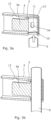
- FIGS 6 to 11 illustrate a second fitting assembly 1' according to the present disclosure.
- the second fitting assembly 1' is similar or identical to the fitting assembly 1 described above with reference to Figures 1 to 5 and as such like reference numerals have been used to label like components.
- the clamp 3' has a pair of opposing fingers 9a' and 9b' extending radially outward from the collar 10 adjacent either side of the split 8 and in addition, each finger 9a' and 9b' comprises a pair of outwardly facing recessed slots 32a and 32b running parallel to each other and parallel to the respective finger.
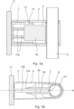
- recessed slots 32a, 32b of the clamp 3' are sized so as to mate with a receiving portion comprising internal ribs 15a' and 15b' on opposing interior surfaces of a bracket 2' which is illustrated in Figure 11 .
- the alternative bracket 2' is similar to the bracket 2 described above except that the ribs 15a' and 15b' are sized to fit snugly within the slots 32a and 32b respectively of the clamp 3'.
- the ribs 15a' and 15b' are also arranged to urge the fingers 9a' and 9b' of the clamp 3' inwards towards each other so as to compress the collar portion 10 at the split 8, thereby clamping the elongate member 5 securely within the collar 10 in the same manner as described above.
- the second fitting assembly 1' may tolerate a load of 60-80kg being applied on the elongate member 5 in a direction parallel to the elongate member as a result of the four contact points resulting from the interlocking of the ribs 15a' and 15b' with the recessed slots 32a and 32b of the clamp 3'.
- the bracket 2' has an outwardly extending peg 14' which is arranged to engage a corresponding notch/hole 13' on the cover 4'.
- the peg 14' and hole 13' have a reverse draft to further improve the locking of the cover 4' onto the bracket 2'.
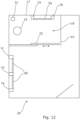
- Figure 12 illustrates a bathroom (washroom) 20 containing a shower area 18 which is formed on two sides by the bathroom wall 17, on a further side by a fixed partition 23 (e.g. formed of glass) and on a fourth side by a sliding door 22 (e.g. formed of glass).
- the shower area contains a shower head 19 and drain 21.
- the shower area could alternatively not require the sliding door 22 or partition 23, e.g. if it is part of a wet room open to the rest of the bathroom 20.
- Inside the shower area 18 an elongate member 5a is supported by two fitting assemblies 1a and 1b according to the present disclosure.
- the elongate member 5a may be a guide rail, a rail for supporting a towel or part of a pipe for carrying water from a supply to a hand-held or overhead shower head, for example.
- three fitting assemblies according to the present disclosure 1c, 1d and 1e are provided on the bathroom wall 17 for supporting a second elongate member 5b, such as a towel rail.
- the central fitting assembly 1d adds further support to the elongate member 5b over the larger expanse.
- the fitting assemblies may be mounted to the wall 17 such that the aperture 12 is in the vertical orientation, rather than horizontal as depicted. This may be applicable when one or more fitting assemblies are used to secure a hose/pipe to the wall, such as a shower hose supplying water to a hand-held or overhead shower head.
- Figure 13 is a flowchart corresponding to a method according to the present disclosure. Specifically, it corresponds to a method of attaching an elongate member 5 to a surface 17 within a shower area 18, the method comprising the steps of:
Landscapes
- Health & Medical Sciences (AREA)
- Public Health (AREA)
- Engineering & Computer Science (AREA)
- General Engineering & Computer Science (AREA)
- Epidemiology (AREA)
- General Health & Medical Sciences (AREA)
- Mechanical Engineering (AREA)
- Architecture (AREA)
- Life Sciences & Earth Sciences (AREA)
- Hydrology & Water Resources (AREA)
- Water Supply & Treatment (AREA)
- Civil Engineering (AREA)
- Structural Engineering (AREA)
- Domestic Plumbing Installations (AREA)
Claims (12)
- Armaturenanordnung (1, 1') zum Befestigen eines länglichen Elements (5) an einer Oberfläche (17) innerhalb eines Dusch- oder Badebereichs, wobei die Armaturenanordnung (1, 1') umfasst:eine Klemme (3, 3'), die einen Kragen (10) umfasst, der angeordnet ist, um das längliche Element (5) aufzunehmen und an diesem anzuliegen, wobei der Kragen (10) einen sich axial erstreckenden Schlitz (8) aufweist, wobei die Klemme (3, 3') weiter einen Finger (9a, 9b, 9a', 9b') umfasst, der sich vom Kragen (10) an eine Seite des Schlitzes (8) angrenzend nach außen erstreckt;eine Abdeckung (4, 4'), die eine Öffnung (12) umfasst, die angeordnet ist, um das längliche Element (5) aufzunehmen, wobei die Abdeckung (4, 4') angeordnet ist, um die Klemme (3, 3') darin festzuhalten, sodass der Kragen (10) axial mit der Öffnung (12) ausgerichtet ist, und weiter angeordnet ist, um eine Drehung der Klemme (3, 3') in Bezug auf die Abdeckung (4, 4') zu verhindern; undeine Halterung (2, 2'), die angeordnet ist, um an der Oberfläche (17) fixiert zu werden und um die Abdeckung (4, 4'), welche die Klemme (3, 3') enthält, aufzunehmen und festzuhalten, wobei die Halterung (2, 2') einen Aufnahmeabschnitt umfasst, der angeordnet ist, um auf den Finger (9a, 9b, 9a', 9b') zu drücken, um den Kragenabschnitt (10) am Schlitz (8) zusammenzudrücken, wodurch das längliche Element (5) innerhalb des Kragens (10) geklemmt wird.
- Armaturenanordnung (1, 1') nach Anspruch 1, wobei die Klemme (3, 3') ein Paar gegenüberliegender Finger (9a, 9b, 9a', 9b') umfasst, die sich aus dem Kragen (10) an jeder Seite des Schlitzes (8) angrenzend nach außen erstrecken, wobei der Aufnahmeabschnitt der Halterung (2, 2') angeordnet ist, um die gegenüberliegenden Finger (9a, 9b, 9a', 9b') aneinander zu drücken, wodurch der Kragenabschnitt (10) am Schlitz (8) zusammengedrückt wird, und das längliche Element (5) innerhalb des Kragens (10) geklemmt wird, wenn die Abdeckung (4, 4'), welche die Klemme (3, 3') enthält, mit der Halterung (2, 2') in Eingriff steht.
- Armaturenanordnung (1, 1') nach Anspruch 1 oder Anspruch 2, wobei die Abdeckung (4, 4') einen oder mehrere Vorsprünge (34) oder Vertiefungen umfasst, die sich an einer Innenoberfläche der Abdeckung (4, 4') befinden, die angeordnet sind, um mit einer oder mehreren entsprechenden Vertiefungen (11) oder Vorsprüngen der Klemme (3, 3') mit einem Schnappsitz in Eingriff zu stehen, um dadurch die Klemme (3, 3') innerhalb der Abdeckung (4, 4') zu halten.
- Armaturenanordnung (1, 1') nach einem der vorstehenden Ansprüche, wobei die Halterung (2, 2') eine oder mehrere Verriegelungslaschen (14) umfasst, die angeordnet sind, um mit einer oder mehreren entsprechenden Kerben (13), die an der Abdeckung (4, 4') bereitgestellt sind, in Eingriff zu stehen, um dadurch die Abdeckung (4, 4') und die Halterung (2, 2') miteinander zu verriegeln, wenn die Abdeckung (4, 4'), welche die Klemme (3, 3') enthält, mit der Halterung (2, 2') in Eingriff steht.
- Armaturenanordnung (1, 1') nach einem der vorstehenden Ansprüche, wobei der Aufnahmeabschnitt eine oder mehrere Rippen (15a, 15b, 15a', 15b') umfasst.
- Armaturenanordnung (1, 1') nach einem der vorstehenden Ansprüche, wobei die Halterung (2, 2') ein Schraubenloch (16) zum Fixieren der Halterung (2, 2') mittels einer Schraube (7) an der Oberfläche (17) umfasst.
- Teilesatz zum Bilden einer Armaturenanordnung (1, 1') nach einem vorstehenden Anspruch.
- Teilesatz nach Anspruch 7, der Mittel zum Fixieren der Halterung (2, 2') der Armaturenanordnung (1, 1') an einer Oberfläche (17), und ein längliches Element (5) umfasst.
- Dusch- oder Badebereich (20), der ein längliches Element (5a, 5b) umfasst, das von einer oder mehreren Armaturenanordnungen (1, 1') nach einem der Ansprüche 1 bis 6 getragen wird.
- Dusch- oder Badebereich (20) nach Anspruch 9, der eine Duschkabine, eine Duschabtrennung und/oder eine Badewanne umfasst.
- Armaturenanordnung (1, 1') nach einem der Ansprüche 1 bis 6, Teilesatz nach Anspruch 7 oder 9 oder Dusch- oder Badebereich (20) nach Anspruch 9 oder Anspruch 10, wobei das längliche Element (5) ein Rohr oder eine Schiene ist.
- Verfahren zum Befestigen eines länglichen Elements (5) an einer Oberfläche (17) innerhalb eines Dusch- oder Badebereichs (20), wobei das Verfahren umfasst:Bereitstellen einer Armaturenanordnung (1, 1') nach einem der Ansprüche 1 bis 6;Fixieren der Halterung (2, 2') an der Oberfläche (17) im Dusch- oder Badebereich (20);Einführen der Klemme (3, 3') in die Abdeckung (4, 4');Einführen des länglichen Elements (5) durch die Öffnung (12) der Abdeckung (4, 4') und den Kragen (10) der Klemme (3, 3') hindurch; undAufschieben der Abdeckung (4, 4'), welche die Klemme (3, 3') enthält, auf die Halterung (2, 2'), wodurch der Aufnahmeabschnitt veranlasst wird, den Finger (9a, 9b, 9a', 9b') zu drücken, um den Kragen (10) um das längliche Element (5) herum festzuziehen.
Applications Claiming Priority (2)
| Application Number | Priority Date | Filing Date | Title |
|---|---|---|---|
| GB1816651.2A GB2577934B (en) | 2018-10-12 | 2018-10-12 | Fitting assembly having clamp for securing elongate member |
| PCT/GB2019/052177 WO2020074851A1 (en) | 2018-10-12 | 2019-08-02 | Fitting assembly |
Publications (2)
| Publication Number | Publication Date |
|---|---|
| EP3864332A1 EP3864332A1 (de) | 2021-08-18 |
| EP3864332B1 true EP3864332B1 (de) | 2024-07-31 |
Family
ID=64397565
Family Applications (1)
| Application Number | Title | Priority Date | Filing Date |
|---|---|---|---|
| EP19750163.8A Active EP3864332B1 (de) | 2018-10-12 | 2019-08-02 | Anschlussanordnung |
Country Status (5)
| Country | Link |
|---|---|
| US (1) | US12075953B2 (de) |
| EP (1) | EP3864332B1 (de) |
| CN (1) | CN112789438B (de) |
| GB (1) | GB2577934B (de) |
| WO (1) | WO2020074851A1 (de) |
Families Citing this family (3)
| Publication number | Priority date | Publication date | Assignee | Title |
|---|---|---|---|---|
| GB2577934B (en) | 2018-10-12 | 2020-09-30 | Kohler Mira Ltd | Fitting assembly having clamp for securing elongate member |
| KR102869054B1 (ko) * | 2020-08-12 | 2025-10-10 | 현대자동차 주식회사 | 프레임 연결 구조 |
| GB2632090A (en) * | 2023-06-19 | 2025-01-29 | Norcros Group Holdings Ltd | A bracket |
Citations (2)
| Publication number | Priority date | Publication date | Assignee | Title |
|---|---|---|---|---|
| EP1529996B1 (de) * | 2003-11-07 | 2009-10-21 | Wermuth Enterprises | Rohrhalterungsvorrichtung |
| CN207285980U (zh) * | 2017-04-28 | 2018-05-01 | 厦门易伯伦科技有限公司 | 一种淋浴器的固定机构 |
Family Cites Families (15)
| Publication number | Priority date | Publication date | Assignee | Title |
|---|---|---|---|---|
| GB183316A (en) | 1921-06-02 | 1922-07-27 | Jesse Henry James | Improved means for securing curtain rods and the like to their brackets or supports |
| GB1556730A (en) * | 1977-08-12 | 1979-11-28 | Critchley Bros Ltd | Rail supporting posts |
| US6257530B1 (en) * | 1999-12-20 | 2001-07-10 | Chin Hai Tsai | Clasping device for longitudinal object |
| JP2004150547A (ja) * | 2002-10-31 | 2004-05-27 | Furukawa Electric Co Ltd:The | 配管支持部材 |
| GB2411447B (en) * | 2004-02-25 | 2006-10-18 | Basic Holdings | Fastening devices |
| US8371549B1 (en) | 2010-08-10 | 2013-02-12 | Brian T. Paquette | Hold for a toothpaste tube and toothbrushes |
| US8382051B2 (en) * | 2010-12-09 | 2013-02-26 | Waxman Consumer Products Group Inc. | Wall-mounted support assembly for bathroom accessories |
| GB201114436D0 (en) * | 2011-08-22 | 2011-10-05 | Airbus Operations Ltd | Fixing means |
| CN104720666B (zh) * | 2013-12-20 | 2017-09-29 | 安东尼·郭 | 浴室挂置装置及包括该浴室挂置装置的浴室挂置装置组件 |
| US9282854B2 (en) * | 2014-01-02 | 2016-03-15 | Hacksaw & Knife Manufactory Co., Ltd. | Bathroom carrying device and bathroom hanging assembly having the same |
| CN206342393U (zh) * | 2016-09-30 | 2017-07-21 | 黄金成 | 一种淋浴杆用可调式安装座 |
| CN206769464U (zh) | 2017-04-20 | 2017-12-19 | 佛山市南海泽宇装饰五金制品有限公司 | 一种淋浴房用安装架 |
| CN107518808A (zh) * | 2017-09-20 | 2017-12-29 | 区洁群 | 一种带安装螺丝一体成型的毛巾架 |
| DE102018209985B4 (de) * | 2018-06-20 | 2025-08-14 | Hansgrohe Se | Stangenmontierbare Halterung |
| GB2577934B (en) | 2018-10-12 | 2020-09-30 | Kohler Mira Ltd | Fitting assembly having clamp for securing elongate member |
-
2018
- 2018-10-12 GB GB1816651.2A patent/GB2577934B/en active Active
-
2019
- 2019-08-02 WO PCT/GB2019/052177 patent/WO2020074851A1/en not_active Ceased
- 2019-08-02 EP EP19750163.8A patent/EP3864332B1/de active Active
- 2019-08-02 CN CN201980065429.XA patent/CN112789438B/zh active Active
-
2021
- 2021-04-09 US US17/226,858 patent/US12075953B2/en active Active
Patent Citations (2)
| Publication number | Priority date | Publication date | Assignee | Title |
|---|---|---|---|---|
| EP1529996B1 (de) * | 2003-11-07 | 2009-10-21 | Wermuth Enterprises | Rohrhalterungsvorrichtung |
| CN207285980U (zh) * | 2017-04-28 | 2018-05-01 | 厦门易伯伦科技有限公司 | 一种淋浴器的固定机构 |
Also Published As
| Publication number | Publication date |
|---|---|
| US12075953B2 (en) | 2024-09-03 |
| GB201816651D0 (en) | 2018-11-28 |
| GB2577934B (en) | 2020-09-30 |
| CN112789438B (zh) | 2022-10-28 |
| GB2577934A (en) | 2020-04-15 |
| US20210219797A1 (en) | 2021-07-22 |
| CN112789438A (zh) | 2021-05-11 |
| WO2020074851A1 (en) | 2020-04-16 |
| EP3864332A1 (de) | 2021-08-18 |
Similar Documents
| Publication | Publication Date | Title |
|---|---|---|
| EP3864332B1 (de) | Anschlussanordnung | |
| CN109715891B (zh) | 洁具用品的壁安装用设备及所述洁具用品的壁安装用方法 | |
| US6158066A (en) | Anti-rotation pipe locator and holder | |
| DK2646726T3 (en) | pipe clamp | |
| US20090206220A1 (en) | Method and apparatus for attaching grab bar to wall flange | |
| EP3680532B1 (de) | Kunststoffrohrschelle | |
| US20050063772A1 (en) | Connection assembly apparatus and method | |
| US11766149B2 (en) | Rod assembly, bracket system for supporting a support rod, and method of mounting the same on a support structure | |
| CZ292095B6 (cs) | Spojovací jednotka | |
| GB2457568A (en) | Insert wall anchor for a grab bar | |
| US8807899B2 (en) | Insert wall anchor for a grab bar | |
| JPH05202542A (ja) | シャワー用壁付けスタンド・パイプ | |
| CZ289088B6 (cs) | Čelní stěnový dílec pro sanitní instalaci | |
| CZ65896A3 (en) | Connecting angle | |
| SK117799A3 (en) | Profile rail and coupling element of supporting device | |
| CA2622666C (en) | Grab bar with insert | |
| RU2800432C1 (ru) | Крепежное устройство для прикрепления санитарно-технического изделия к стене и способ прикрепления | |
| KR200172823Y1 (ko) | 압착가설식 선반 | |
| CA2769921A1 (en) | Insert wall anchor for a grab bar | |
| CN216962252U (zh) | 一种快装置物盘 | |
| KR20260000390U (ko) | 욕실용 설비 고정장치 | |
| KR200237567Y1 (ko) | 가구용 걸이대 연결장치 | |
| KR200363248Y1 (ko) | 욕실용 코너선반 | |
| EP1500364A2 (de) | Verbindungsanordnung | |
| KR20250136002A (ko) | 욕실용품의 무타공 시공용 고정걸이구 |
Legal Events
| Date | Code | Title | Description |
|---|---|---|---|
| STAA | Information on the status of an ep patent application or granted ep patent |
Free format text: STATUS: UNKNOWN |
|
| STAA | Information on the status of an ep patent application or granted ep patent |
Free format text: STATUS: THE INTERNATIONAL PUBLICATION HAS BEEN MADE |
|
| PUAI | Public reference made under article 153(3) epc to a published international application that has entered the european phase |
Free format text: ORIGINAL CODE: 0009012 |
|
| STAA | Information on the status of an ep patent application or granted ep patent |
Free format text: STATUS: REQUEST FOR EXAMINATION WAS MADE |
|
| 17P | Request for examination filed |
Effective date: 20210212 |
|
| AK | Designated contracting states |
Kind code of ref document: A1 Designated state(s): AL AT BE BG CH CY CZ DE DK EE ES FI FR GB GR HR HU IE IS IT LI LT LU LV MC MK MT NL NO PL PT RO RS SE SI SK SM TR |
|
| DAV | Request for validation of the european patent (deleted) | ||
| DAX | Request for extension of the european patent (deleted) | ||
| STAA | Information on the status of an ep patent application or granted ep patent |
Free format text: STATUS: EXAMINATION IS IN PROGRESS |
|
| 17Q | First examination report despatched |
Effective date: 20230210 |
|
| GRAP | Despatch of communication of intention to grant a patent |
Free format text: ORIGINAL CODE: EPIDOSNIGR1 |
|
| STAA | Information on the status of an ep patent application or granted ep patent |
Free format text: STATUS: GRANT OF PATENT IS INTENDED |
|
| INTG | Intention to grant announced |
Effective date: 20240514 |
|
| GRAS | Grant fee paid |
Free format text: ORIGINAL CODE: EPIDOSNIGR3 |
|
| GRAA | (expected) grant |
Free format text: ORIGINAL CODE: 0009210 |
|
| STAA | Information on the status of an ep patent application or granted ep patent |
Free format text: STATUS: THE PATENT HAS BEEN GRANTED |
|
| RBV | Designated contracting states (corrected) |
Designated state(s): AL AT BE BG CH CY CZ DE DK EE ES FI FR GR HR HU IE IS IT LI LT LU LV MC MK MT NL NO PL PT RO RS SE SI SK SM TR |
|
| AK | Designated contracting states |
Kind code of ref document: B1 Designated state(s): AL AT BE BG CH CY CZ DE DK EE ES FI FR GR HR HU IE IS IT LI LT LU LV MC MK MT NL NO PL PT RO RS SE SI SK SM TR |
|
| REG | Reference to a national code |
Ref country code: CH Ref legal event code: EP |
|
| REG | Reference to a national code |
Ref country code: DE Ref legal event code: R096 Ref document number: 602019056124 Country of ref document: DE |
|
| REG | Reference to a national code |
Ref country code: IE Ref legal event code: FG4D |
|
| REG | Reference to a national code |
Ref country code: LT Ref legal event code: MG9D |
|
| REG | Reference to a national code |
Ref country code: NL Ref legal event code: MP Effective date: 20240731 |
|
| PG25 | Lapsed in a contracting state [announced via postgrant information from national office to epo] |
Ref country code: PT Free format text: LAPSE BECAUSE OF FAILURE TO SUBMIT A TRANSLATION OF THE DESCRIPTION OR TO PAY THE FEE WITHIN THE PRESCRIBED TIME-LIMIT Effective date: 20241202 |
|
| REG | Reference to a national code |
Ref country code: AT Ref legal event code: MK05 Ref document number: 1708740 Country of ref document: AT Kind code of ref document: T Effective date: 20240731 |
|
| PG25 | Lapsed in a contracting state [announced via postgrant information from national office to epo] |
Ref country code: PT Free format text: LAPSE BECAUSE OF FAILURE TO SUBMIT A TRANSLATION OF THE DESCRIPTION OR TO PAY THE FEE WITHIN THE PRESCRIBED TIME-LIMIT Effective date: 20241202 |
|
| PG25 | Lapsed in a contracting state [announced via postgrant information from national office to epo] |
Ref country code: NO Free format text: LAPSE BECAUSE OF FAILURE TO SUBMIT A TRANSLATION OF THE DESCRIPTION OR TO PAY THE FEE WITHIN THE PRESCRIBED TIME-LIMIT Effective date: 20241031 |
|
| PG25 | Lapsed in a contracting state [announced via postgrant information from national office to epo] |
Ref country code: NL Free format text: LAPSE BECAUSE OF FAILURE TO SUBMIT A TRANSLATION OF THE DESCRIPTION OR TO PAY THE FEE WITHIN THE PRESCRIBED TIME-LIMIT Effective date: 20240731 Ref country code: FI Free format text: LAPSE BECAUSE OF FAILURE TO SUBMIT A TRANSLATION OF THE DESCRIPTION OR TO PAY THE FEE WITHIN THE PRESCRIBED TIME-LIMIT Effective date: 20240731 Ref country code: GR Free format text: LAPSE BECAUSE OF FAILURE TO SUBMIT A TRANSLATION OF THE DESCRIPTION OR TO PAY THE FEE WITHIN THE PRESCRIBED TIME-LIMIT Effective date: 20241101 Ref country code: PL Free format text: LAPSE BECAUSE OF FAILURE TO SUBMIT A TRANSLATION OF THE DESCRIPTION OR TO PAY THE FEE WITHIN THE PRESCRIBED TIME-LIMIT Effective date: 20240731 |
|
| PG25 | Lapsed in a contracting state [announced via postgrant information from national office to epo] |
Ref country code: BG Free format text: LAPSE BECAUSE OF FAILURE TO SUBMIT A TRANSLATION OF THE DESCRIPTION OR TO PAY THE FEE WITHIN THE PRESCRIBED TIME-LIMIT Effective date: 20240731 |
|
| PG25 | Lapsed in a contracting state [announced via postgrant information from national office to epo] |
Ref country code: LV Free format text: LAPSE BECAUSE OF FAILURE TO SUBMIT A TRANSLATION OF THE DESCRIPTION OR TO PAY THE FEE WITHIN THE PRESCRIBED TIME-LIMIT Effective date: 20240731 |
|
| PG25 | Lapsed in a contracting state [announced via postgrant information from national office to epo] |
Ref country code: IS Free format text: LAPSE BECAUSE OF FAILURE TO SUBMIT A TRANSLATION OF THE DESCRIPTION OR TO PAY THE FEE WITHIN THE PRESCRIBED TIME-LIMIT Effective date: 20241130 Ref country code: AT Free format text: LAPSE BECAUSE OF FAILURE TO SUBMIT A TRANSLATION OF THE DESCRIPTION OR TO PAY THE FEE WITHIN THE PRESCRIBED TIME-LIMIT Effective date: 20240731 |
|
| PG25 | Lapsed in a contracting state [announced via postgrant information from national office to epo] |
Ref country code: HR Free format text: LAPSE BECAUSE OF FAILURE TO SUBMIT A TRANSLATION OF THE DESCRIPTION OR TO PAY THE FEE WITHIN THE PRESCRIBED TIME-LIMIT Effective date: 20240731 |
|
| PG25 | Lapsed in a contracting state [announced via postgrant information from national office to epo] |
Ref country code: ES Free format text: LAPSE BECAUSE OF FAILURE TO SUBMIT A TRANSLATION OF THE DESCRIPTION OR TO PAY THE FEE WITHIN THE PRESCRIBED TIME-LIMIT Effective date: 20240731 Ref country code: RS Free format text: LAPSE BECAUSE OF FAILURE TO SUBMIT A TRANSLATION OF THE DESCRIPTION OR TO PAY THE FEE WITHIN THE PRESCRIBED TIME-LIMIT Effective date: 20241031 |
|
| PG25 | Lapsed in a contracting state [announced via postgrant information from national office to epo] |
Ref country code: RS Free format text: LAPSE BECAUSE OF FAILURE TO SUBMIT A TRANSLATION OF THE DESCRIPTION OR TO PAY THE FEE WITHIN THE PRESCRIBED TIME-LIMIT Effective date: 20241031 Ref country code: PL Free format text: LAPSE BECAUSE OF FAILURE TO SUBMIT A TRANSLATION OF THE DESCRIPTION OR TO PAY THE FEE WITHIN THE PRESCRIBED TIME-LIMIT Effective date: 20240731 Ref country code: NO Free format text: LAPSE BECAUSE OF FAILURE TO SUBMIT A TRANSLATION OF THE DESCRIPTION OR TO PAY THE FEE WITHIN THE PRESCRIBED TIME-LIMIT Effective date: 20241031 Ref country code: NL Free format text: LAPSE BECAUSE OF FAILURE TO SUBMIT A TRANSLATION OF THE DESCRIPTION OR TO PAY THE FEE WITHIN THE PRESCRIBED TIME-LIMIT Effective date: 20240731 Ref country code: LV Free format text: LAPSE BECAUSE OF FAILURE TO SUBMIT A TRANSLATION OF THE DESCRIPTION OR TO PAY THE FEE WITHIN THE PRESCRIBED TIME-LIMIT Effective date: 20240731 Ref country code: IS Free format text: LAPSE BECAUSE OF FAILURE TO SUBMIT A TRANSLATION OF THE DESCRIPTION OR TO PAY THE FEE WITHIN THE PRESCRIBED TIME-LIMIT Effective date: 20241130 Ref country code: HR Free format text: LAPSE BECAUSE OF FAILURE TO SUBMIT A TRANSLATION OF THE DESCRIPTION OR TO PAY THE FEE WITHIN THE PRESCRIBED TIME-LIMIT Effective date: 20240731 Ref country code: GR Free format text: LAPSE BECAUSE OF FAILURE TO SUBMIT A TRANSLATION OF THE DESCRIPTION OR TO PAY THE FEE WITHIN THE PRESCRIBED TIME-LIMIT Effective date: 20241101 Ref country code: FI Free format text: LAPSE BECAUSE OF FAILURE TO SUBMIT A TRANSLATION OF THE DESCRIPTION OR TO PAY THE FEE WITHIN THE PRESCRIBED TIME-LIMIT Effective date: 20240731 Ref country code: ES Free format text: LAPSE BECAUSE OF FAILURE TO SUBMIT A TRANSLATION OF THE DESCRIPTION OR TO PAY THE FEE WITHIN THE PRESCRIBED TIME-LIMIT Effective date: 20240731 Ref country code: BG Free format text: LAPSE BECAUSE OF FAILURE TO SUBMIT A TRANSLATION OF THE DESCRIPTION OR TO PAY THE FEE WITHIN THE PRESCRIBED TIME-LIMIT Effective date: 20240731 Ref country code: AT Free format text: LAPSE BECAUSE OF FAILURE TO SUBMIT A TRANSLATION OF THE DESCRIPTION OR TO PAY THE FEE WITHIN THE PRESCRIBED TIME-LIMIT Effective date: 20240731 |
|
| REG | Reference to a national code |
Ref country code: CH Ref legal event code: PL |
|
| PG25 | Lapsed in a contracting state [announced via postgrant information from national office to epo] |
Ref country code: RO Free format text: LAPSE BECAUSE OF FAILURE TO SUBMIT A TRANSLATION OF THE DESCRIPTION OR TO PAY THE FEE WITHIN THE PRESCRIBED TIME-LIMIT Effective date: 20240731 Ref country code: DK Free format text: LAPSE BECAUSE OF FAILURE TO SUBMIT A TRANSLATION OF THE DESCRIPTION OR TO PAY THE FEE WITHIN THE PRESCRIBED TIME-LIMIT Effective date: 20240731 Ref country code: SM Free format text: LAPSE BECAUSE OF FAILURE TO SUBMIT A TRANSLATION OF THE DESCRIPTION OR TO PAY THE FEE WITHIN THE PRESCRIBED TIME-LIMIT Effective date: 20240731 |
|
| PG25 | Lapsed in a contracting state [announced via postgrant information from national office to epo] |
Ref country code: LU Free format text: LAPSE BECAUSE OF NON-PAYMENT OF DUE FEES Effective date: 20240802 |
|
| PG25 | Lapsed in a contracting state [announced via postgrant information from national office to epo] |
Ref country code: MC Free format text: LAPSE BECAUSE OF FAILURE TO SUBMIT A TRANSLATION OF THE DESCRIPTION OR TO PAY THE FEE WITHIN THE PRESCRIBED TIME-LIMIT Effective date: 20240731 Ref country code: EE Free format text: LAPSE BECAUSE OF FAILURE TO SUBMIT A TRANSLATION OF THE DESCRIPTION OR TO PAY THE FEE WITHIN THE PRESCRIBED TIME-LIMIT Effective date: 20240731 Ref country code: CH Free format text: LAPSE BECAUSE OF NON-PAYMENT OF DUE FEES Effective date: 20240831 |
|
| PG25 | Lapsed in a contracting state [announced via postgrant information from national office to epo] |
Ref country code: CZ Free format text: LAPSE BECAUSE OF FAILURE TO SUBMIT A TRANSLATION OF THE DESCRIPTION OR TO PAY THE FEE WITHIN THE PRESCRIBED TIME-LIMIT Effective date: 20240731 |
|
| PG25 | Lapsed in a contracting state [announced via postgrant information from national office to epo] |
Ref country code: IT Free format text: LAPSE BECAUSE OF FAILURE TO SUBMIT A TRANSLATION OF THE DESCRIPTION OR TO PAY THE FEE WITHIN THE PRESCRIBED TIME-LIMIT Effective date: 20240731 Ref country code: SK Free format text: LAPSE BECAUSE OF FAILURE TO SUBMIT A TRANSLATION OF THE DESCRIPTION OR TO PAY THE FEE WITHIN THE PRESCRIBED TIME-LIMIT Effective date: 20240731 |
|
| REG | Reference to a national code |
Ref country code: DE Ref legal event code: R097 Ref document number: 602019056124 Country of ref document: DE |
|
| PLBE | No opposition filed within time limit |
Free format text: ORIGINAL CODE: 0009261 |
|
| STAA | Information on the status of an ep patent application or granted ep patent |
Free format text: STATUS: NO OPPOSITION FILED WITHIN TIME LIMIT |
|
| REG | Reference to a national code |
Ref country code: BE Ref legal event code: MM Effective date: 20240831 |
|
| 26N | No opposition filed |
Effective date: 20250501 |
|
| PG25 | Lapsed in a contracting state [announced via postgrant information from national office to epo] |
Ref country code: BE Free format text: LAPSE BECAUSE OF NON-PAYMENT OF DUE FEES Effective date: 20240831 |
|
| PG25 | Lapsed in a contracting state [announced via postgrant information from national office to epo] |
Ref country code: SE Free format text: LAPSE BECAUSE OF FAILURE TO SUBMIT A TRANSLATION OF THE DESCRIPTION OR TO PAY THE FEE WITHIN THE PRESCRIBED TIME-LIMIT Effective date: 20240731 |
|
| PGFP | Annual fee paid to national office [announced via postgrant information from national office to epo] |
Ref country code: DE Payment date: 20250827 Year of fee payment: 7 |
|
| PGFP | Annual fee paid to national office [announced via postgrant information from national office to epo] |
Ref country code: FR Payment date: 20250827 Year of fee payment: 7 |
|
| PGFP | Annual fee paid to national office [announced via postgrant information from national office to epo] |
Ref country code: IE Payment date: 20250828 Year of fee payment: 7 |
|
| PG25 | Lapsed in a contracting state [announced via postgrant information from national office to epo] |
Ref country code: CY Free format text: LAPSE BECAUSE OF FAILURE TO SUBMIT A TRANSLATION OF THE DESCRIPTION OR TO PAY THE FEE WITHIN THE PRESCRIBED TIME-LIMIT; INVALID AB INITIO Effective date: 20190802 |
|
| PG25 | Lapsed in a contracting state [announced via postgrant information from national office to epo] |
Ref country code: HU Free format text: LAPSE BECAUSE OF FAILURE TO SUBMIT A TRANSLATION OF THE DESCRIPTION OR TO PAY THE FEE WITHIN THE PRESCRIBED TIME-LIMIT; INVALID AB INITIO Effective date: 20190802 |