EP3864299B1 - Turbinenmotor mit einem rotor mit schaufeln mit verstellbarer neigung - Google Patents
Turbinenmotor mit einem rotor mit schaufeln mit verstellbarer neigung Download PDFInfo
- Publication number
- EP3864299B1 EP3864299B1 EP19817382.5A EP19817382A EP3864299B1 EP 3864299 B1 EP3864299 B1 EP 3864299B1 EP 19817382 A EP19817382 A EP 19817382A EP 3864299 B1 EP3864299 B1 EP 3864299B1
- Authority
- EP
- European Patent Office
- Prior art keywords
- rotor
- actuator
- blade
- turbine engine
- bearing
- Prior art date
- Legal status (The legal status is an assumption and is not a legal conclusion. Google has not performed a legal analysis and makes no representation as to the accuracy of the status listed.)
- Active
Links
Images

Classifications
-
- F—MECHANICAL ENGINEERING; LIGHTING; HEATING; WEAPONS; BLASTING
- F01—MACHINES OR ENGINES IN GENERAL; ENGINE PLANTS IN GENERAL; STEAM ENGINES
- F01D—NON-POSITIVE DISPLACEMENT MACHINES OR ENGINES, e.g. STEAM TURBINES
- F01D7/00—Rotors with blades adjustable in operation; Control thereof
-
- F—MECHANICAL ENGINEERING; LIGHTING; HEATING; WEAPONS; BLASTING
- F04—POSITIVE - DISPLACEMENT MACHINES FOR LIQUIDS; PUMPS FOR LIQUIDS OR ELASTIC FLUIDS
- F04D—NON-POSITIVE-DISPLACEMENT PUMPS
- F04D29/00—Details, component parts, or accessories
- F04D29/26—Rotors specially for elastic fluids
- F04D29/32—Rotors specially for elastic fluids for axial flow pumps
- F04D29/321—Rotors specially for elastic fluids for axial flow pumps for axial flow compressors
- F04D29/322—Blade mountings
- F04D29/323—Blade mountings adjustable
-
- B—PERFORMING OPERATIONS; TRANSPORTING
- B64—AIRCRAFT; AVIATION; COSMONAUTICS
- B64C—AEROPLANES; HELICOPTERS
- B64C11/00—Propellers, e.g. of ducted type; Features common to propellers and rotors for rotorcraft
- B64C11/30—Blade pitch-changing mechanisms
- B64C11/38—Blade pitch-changing mechanisms fluid, e.g. hydraulic
-
- B—PERFORMING OPERATIONS; TRANSPORTING
- B64—AIRCRAFT; AVIATION; COSMONAUTICS
- B64C—AEROPLANES; HELICOPTERS
- B64C11/00—Propellers, e.g. of ducted type; Features common to propellers and rotors for rotorcraft
- B64C11/30—Blade pitch-changing mechanisms
- B64C11/44—Blade pitch-changing mechanisms electric
-
- F—MECHANICAL ENGINEERING; LIGHTING; HEATING; WEAPONS; BLASTING
- F01—MACHINES OR ENGINES IN GENERAL; ENGINE PLANTS IN GENERAL; STEAM ENGINES
- F01D—NON-POSITIVE DISPLACEMENT MACHINES OR ENGINES, e.g. STEAM TURBINES
- F01D25/00—Component parts, details, or accessories, not provided for in, or of interest apart from, other groups
- F01D25/16—Arrangement of bearings; Supporting or mounting bearings in casings
-
- F—MECHANICAL ENGINEERING; LIGHTING; HEATING; WEAPONS; BLASTING
- F02—COMBUSTION ENGINES; HOT-GAS OR COMBUSTION-PRODUCT ENGINE PLANTS
- F02K—JET-PROPULSION PLANTS
- F02K3/00—Plants including a gas turbine driving a compressor or a ducted fan
- F02K3/02—Plants including a gas turbine driving a compressor or a ducted fan in which part of the working fluid by-passes the turbine and combustion chamber
- F02K3/04—Plants including a gas turbine driving a compressor or a ducted fan in which part of the working fluid by-passes the turbine and combustion chamber the plant including ducted fans, i.e. fans with high volume, low pressure outputs, for augmenting the jet thrust, e.g. of double-flow type
- F02K3/06—Plants including a gas turbine driving a compressor or a ducted fan in which part of the working fluid by-passes the turbine and combustion chamber the plant including ducted fans, i.e. fans with high volume, low pressure outputs, for augmenting the jet thrust, e.g. of double-flow type with front fan
-
- F—MECHANICAL ENGINEERING; LIGHTING; HEATING; WEAPONS; BLASTING
- F04—POSITIVE - DISPLACEMENT MACHINES FOR LIQUIDS; PUMPS FOR LIQUIDS OR ELASTIC FLUIDS
- F04D—NON-POSITIVE-DISPLACEMENT PUMPS
- F04D29/00—Details, component parts, or accessories
- F04D29/26—Rotors specially for elastic fluids
- F04D29/32—Rotors specially for elastic fluids for axial flow pumps
- F04D29/34—Blade mountings
- F04D29/36—Blade mountings adjustable
-
- F—MECHANICAL ENGINEERING; LIGHTING; HEATING; WEAPONS; BLASTING
- F05—INDEXING SCHEMES RELATING TO ENGINES OR PUMPS IN VARIOUS SUBCLASSES OF CLASSES F01-F04
- F05D—INDEXING SCHEME FOR ASPECTS RELATING TO NON-POSITIVE-DISPLACEMENT MACHINES OR ENGINES, GAS-TURBINES OR JET-PROPULSION PLANTS
- F05D2220/00—Application
- F05D2220/30—Application in turbines
- F05D2220/32—Application in turbines in gas turbines
-
- F—MECHANICAL ENGINEERING; LIGHTING; HEATING; WEAPONS; BLASTING
- F05—INDEXING SCHEMES RELATING TO ENGINES OR PUMPS IN VARIOUS SUBCLASSES OF CLASSES F01-F04
- F05D—INDEXING SCHEME FOR ASPECTS RELATING TO NON-POSITIVE-DISPLACEMENT MACHINES OR ENGINES, GAS-TURBINES OR JET-PROPULSION PLANTS
- F05D2220/00—Application
- F05D2220/30—Application in turbines
- F05D2220/36—Application in turbines specially adapted for the fan of turbofan engines
-
- F—MECHANICAL ENGINEERING; LIGHTING; HEATING; WEAPONS; BLASTING
- F05—INDEXING SCHEMES RELATING TO ENGINES OR PUMPS IN VARIOUS SUBCLASSES OF CLASSES F01-F04
- F05D—INDEXING SCHEME FOR ASPECTS RELATING TO NON-POSITIVE-DISPLACEMENT MACHINES OR ENGINES, GAS-TURBINES OR JET-PROPULSION PLANTS
- F05D2240/00—Components
- F05D2240/20—Rotors
- F05D2240/30—Characteristics of rotor blades, i.e. of any element transforming dynamic fluid energy to or from rotational energy and being attached to a rotor
-
- F—MECHANICAL ENGINEERING; LIGHTING; HEATING; WEAPONS; BLASTING
- F05—INDEXING SCHEMES RELATING TO ENGINES OR PUMPS IN VARIOUS SUBCLASSES OF CLASSES F01-F04
- F05D—INDEXING SCHEME FOR ASPECTS RELATING TO NON-POSITIVE-DISPLACEMENT MACHINES OR ENGINES, GAS-TURBINES OR JET-PROPULSION PLANTS
- F05D2240/00—Components
- F05D2240/50—Bearings
- F05D2240/54—Radial bearings
-
- F—MECHANICAL ENGINEERING; LIGHTING; HEATING; WEAPONS; BLASTING
- F05—INDEXING SCHEMES RELATING TO ENGINES OR PUMPS IN VARIOUS SUBCLASSES OF CLASSES F01-F04
- F05D—INDEXING SCHEME FOR ASPECTS RELATING TO NON-POSITIVE-DISPLACEMENT MACHINES OR ENGINES, GAS-TURBINES OR JET-PROPULSION PLANTS
- F05D2250/00—Geometry
- F05D2250/20—Three-dimensional
- F05D2250/23—Three-dimensional prismatic
- F05D2250/231—Three-dimensional prismatic cylindrical
-
- F—MECHANICAL ENGINEERING; LIGHTING; HEATING; WEAPONS; BLASTING
- F05—INDEXING SCHEMES RELATING TO ENGINES OR PUMPS IN VARIOUS SUBCLASSES OF CLASSES F01-F04
- F05D—INDEXING SCHEME FOR ASPECTS RELATING TO NON-POSITIVE-DISPLACEMENT MACHINES OR ENGINES, GAS-TURBINES OR JET-PROPULSION PLANTS
- F05D2260/00—Function
- F05D2260/40—Transmission of power
- F05D2260/403—Transmission of power through the shape of the drive components
- F05D2260/4031—Transmission of power through the shape of the drive components as in toothed gearing
- F05D2260/40311—Transmission of power through the shape of the drive components as in toothed gearing of the epicyclical, planetary or differential type
-
- F—MECHANICAL ENGINEERING; LIGHTING; HEATING; WEAPONS; BLASTING
- F05—INDEXING SCHEMES RELATING TO ENGINES OR PUMPS IN VARIOUS SUBCLASSES OF CLASSES F01-F04
- F05D—INDEXING SCHEME FOR ASPECTS RELATING TO NON-POSITIVE-DISPLACEMENT MACHINES OR ENGINES, GAS-TURBINES OR JET-PROPULSION PLANTS
- F05D2260/00—Function
- F05D2260/70—Adjusting of angle of incidence or attack of rotating blades
- F05D2260/76—Adjusting of angle of incidence or attack of rotating blades the adjusting mechanism using auxiliary power sources
-
- F—MECHANICAL ENGINEERING; LIGHTING; HEATING; WEAPONS; BLASTING
- F05—INDEXING SCHEMES RELATING TO ENGINES OR PUMPS IN VARIOUS SUBCLASSES OF CLASSES F01-F04
- F05D—INDEXING SCHEME FOR ASPECTS RELATING TO NON-POSITIVE-DISPLACEMENT MACHINES OR ENGINES, GAS-TURBINES OR JET-PROPULSION PLANTS
- F05D2270/00—Control
- F05D2270/50—Control logic embodiments
- F05D2270/52—Control logic embodiments by electrical means, e.g. relays or switches
-
- F—MECHANICAL ENGINEERING; LIGHTING; HEATING; WEAPONS; BLASTING
- F05—INDEXING SCHEMES RELATING TO ENGINES OR PUMPS IN VARIOUS SUBCLASSES OF CLASSES F01-F04
- F05D—INDEXING SCHEME FOR ASPECTS RELATING TO NON-POSITIVE-DISPLACEMENT MACHINES OR ENGINES, GAS-TURBINES OR JET-PROPULSION PLANTS
- F05D2270/00—Control
- F05D2270/50—Control logic embodiments
- F05D2270/56—Control logic embodiments by hydraulic means, e.g. hydraulic valves within a hydraulic circuit
-
- F—MECHANICAL ENGINEERING; LIGHTING; HEATING; WEAPONS; BLASTING
- F05—INDEXING SCHEMES RELATING TO ENGINES OR PUMPS IN VARIOUS SUBCLASSES OF CLASSES F01-F04
- F05D—INDEXING SCHEME FOR ASPECTS RELATING TO NON-POSITIVE-DISPLACEMENT MACHINES OR ENGINES, GAS-TURBINES OR JET-PROPULSION PLANTS
- F05D2270/00—Control
- F05D2270/60—Control system actuates means
- F05D2270/62—Electrical actuators
-
- F—MECHANICAL ENGINEERING; LIGHTING; HEATING; WEAPONS; BLASTING
- F05—INDEXING SCHEMES RELATING TO ENGINES OR PUMPS IN VARIOUS SUBCLASSES OF CLASSES F01-F04
- F05D—INDEXING SCHEME FOR ASPECTS RELATING TO NON-POSITIVE-DISPLACEMENT MACHINES OR ENGINES, GAS-TURBINES OR JET-PROPULSION PLANTS
- F05D2270/00—Control
- F05D2270/60—Control system actuates means
- F05D2270/64—Hydraulic actuators
Definitions
- the present invention relates to a turbomachine comprising a rotor carrying blades with variable pitch, and more precisely an engine architecture optimized and adapted to such a turbomachine.
- a turbomachine may comprise a rotor provided with blades with variable pitch, i.e. blades whose pitch (and more precisely the pitch angle) is adjustable as a function of the flight parameters, so as to optimize the operation of the turbomachine.
- the pitch angle of a blade corresponds to the angle, in a longitudinal plane perpendicular to the axis of rotation of the blade, between the chord of the blade and the plane of rotation of the rotor.
- Such a turbomachine includes a blade pitch control system.
- the control system generally comprises an actuator common to all the blades and a mechanism specific to each of the blades, this mechanism being configured to transform the movement initiated by the actuator into a rotary movement of the corresponding blade.
- the actuator is integral with the fixed structure of the turbomachine (and in other words placed in a fixed reference) and the different mechanisms are integral with the rotor (and in other words placed in a rotating reference).
- the control system further comprises a load transfer bearing (better known by the English acronym LTB for “Load Transfer Bearing”) making it possible to ensure the transmission of the movement initiated by the actuator (fixed reference) to the mechanisms (reference rotating).
- the movement of the actuator makes it possible to synchronously adjust the pitch of all the blades via the load transfer bearing and the various mechanisms.
- the control system (namely the actuator and the mechanisms) is positioned in a closed annular enclosure delimited by the rotor.
- the actuator here is a hydraulic actuator.
- the control system thus includes a rotating connection (or rotating joint) making it possible to transfer hydraulic energy from the fixed reference to the rotating reference.
- Having the actuator in a rotating frame makes it possible to not need a load transfer bearing to transmit the movement of the actuator from the fixed frame to the rotating frame but also to not need to use telescopic easements necessary for the hydraulic supply of the actuator.
- the architecture described in the aforementioned document has drawbacks.
- the rotor has a significant mass and size.
- the rotor has a parallelogram shape in section, internally defining the enclosure in which the control system is placed.
- such an architecture presents a disadvantage during a maintenance operation on the control system. Indeed, during such a maintenance operation, it is necessary to dismantle the rotor in order to access the control system placed inside, to the detriment of productivity.
- the prior art also includes the documents US-A-2850103 , GB-A-2285098 , FR-A1-3050433 And GB-A-2461786 .
- the objective of the present invention is thus to propose a turbomachine having an optimized engine architecture making it possible to remedy the drawbacks and meet the aforementioned expectations.
- control system namely upstream of the first and second bearings and in the internal space, makes it possible to simplify the rotor, and consequently to reduce the mass and bulk of the latter, but also to significantly simplify maintenance of the control system. In fact, to access the control system, simply remove the inlet cone.
- the fact of axially arranging the transfer device between the first bearing and the second bearing makes it possible to avoid the appearance of hydraulic leaks (when the energy transferred is hydraulic energy) and to maximize the service life. of the last. In fact, the angular travel is reduced as much as possible at the portion of the rotor located axially between the first bearing and the second bearing. Thus, when the turbomachine is in operation, the mechanical stresses of the mobile member on the fixed member are minimized.
- turbomachine 1 of longitudinal axis variable timing 5.
- the fan 2 is placed upstream of a gas generator comprising for example a low pressure compressor, a high pressure compressor, a combustion chamber, a high pressure turbine and a low pressure turbine.
- upstream and downstream are defined in relation to the direction of gas circulation in the fan 2 (or the turbomachine 1).
- the terms “internal”, “external”, “interior” and “exterior” are defined radially with respect to the longitudinal axis X of the turbomachine 1, which is in particular the axis of rotation of compressor and turbine rotors.
- the rotor 3 is guided in rotation relative to the fixed structure 4 of the turbomachine 1 via a first bearing 6 and a second bearing 7.
- the turbomachine 1 comprises a system for controlling the timing 8 of at least one blade 5.
- the system control 8 is integral with the rotor 3 and comprises at least a first actuator 9 set in motion (or actuated) by energy.
- the control system 8 is arranged axially upstream of the first and second bearings 6, 7.
- the turbomachine 1 further comprises an energy transfer device 10 arranged axially between the first bearing 6 and the second bearing 7.
- the control device transfer 10 comprises a fixed member 11 secured to the fixed structure 4 and a movable member 12 secured to the rotor 3.
- the rotor 3 is annular and defines an open internal space 13 towards the upstream in which said control system 8 is placed.
- the engine architecture according to the invention could for example be incorporated into the rotor of an unducted fan of a turbomachine, and in particular a turbomachine better known under the English designation "Open Rotor” which generally comprises a unducted blower or two counter-rotating unducted blowers.
- a turbomachine better known under the English designation "Open Rotor” which generally comprises a unducted blower or two counter-rotating unducted blowers.
- the engine architecture according to the invention could be adapted more particularly to the rotor of the downstream fan.
- the engine architecture according to the invention could be adapted more particularly to the rotor of the upstream fan.
- the rotor 3 comprises a support ring 14 of the blades 5 and an annular shaft 15 having a frustoconical portion 16 and a cylindrical portion 17 on which are attached the first and second bearings 6, 7 as well as the movable member 12 of the device transfer 10.
- the rotor 3 is guided in rotation relative to an annular support 18 of the fixed structure 4.
- the rotor 3 is driven in rotation by a turbine shaft via a speed reducer 19.
- the reducer 19 is here of the epicyclic type .
- the rotor 3 is coupled in rotation to a planet carrier of the gearbox 19, the planet carrier forming the output shaft of the gearbox 19.
- the rotor 3 further comprises an input cone 20 centered on the axis flaring from upstream to downstream. Dismantling the inlet cone 20 allows access to the control system 8, particularly during a maintenance operation.
- the support 18 is attached to an internal hub 21 of an intermediate casing 22.
- the support 18 comprises an upstream wall 23 frustoconical, a downstream wall 24 frustoconical and a tubular cylindrical wall 25 in which the first bearing 6 and the fixed member 11 of the transfer device 10 are housed.
- the second bearing 7 is housed in an opening made in the downstream wall 24.
- the cylindrical wall 25 is arranged axially between the upstream wall 23 and the downstream wall 24.
- the upstream and downstream walls 23, 24, and the cylindrical portion 17 of the shaft 15 define between them an annular enclosure 26 (commonly called "oil enclosure") in which the first and second bearings 6, 7 are housed and lubricated.
- the upstream and downstream walls 23, 24 widen from upstream to downstream.
- the cylindrical wall 25 extends here from the internal end of the upstream wall 23.
- the first and second bearings 6, 7 respectively guide the shaft 15 of the rotor 3 in rotation relative to the cylindrical wall 25 and the downstream wall 24 of the support 18.
- the first bearing 6 is arranged upstream of the second bearing 7.
- the first bearing 6 is for example a roller bearing.
- the second bearing 7 is for example a ball bearing.
- Sealing means 27 are placed upstream of the first bearing 6 between the cylindrical wall 25 and the cylindrical portion 17 of the shaft 15, so as to guarantee the sealing of the enclosure 26.
- the support 18 could be broken down into two distinct sets, namely a first set comprising the upstream wall 23 and the cylindrical wall 25 and a second set comprising only the downstream wall 24.
- the two sets would then be clamped on the internal hub via common fixing means such as screws.
- each blade 5 comprises a foot 28 mounted in a housing 29 of the ring 14 via two bearings 30 so that the blade 5 is movable in rotation around an axis Y substantially perpendicular to the axis X.
- the ring 14 is arranged upstream of the shaft 15.
- the frustoconical portion 16 of the shaft 15 is arranged upstream of the cylindrical portion 17 of the shaft 15.
- the frustoconical portion 16 flares from downstream to upstream.
- the ring 14 has a diameter greater than that of the cylindrical portion 17 of the shaft 15.
- the control system 8 is placed under the ring 14.
- the control system 8 comprises at least a first actuator 9 and a mechanism 31 specific to each of the blades 5.
- the control system 8 comprises either a first actuator 9 per blade 5 or one or more first actuators 9 for all of the blades 5.
- control system 8 comprises a first actuator 9 common to all the blades 5 and a mechanism 31 specific to each of the blades 5, this mechanism 31 making it possible to transform the movement initiated by the first actuator 9 into a rotational movement of the corresponding blade 5.
- the movement of the first actuator 9 makes it possible to synchronously adjust the timing of all the blades 5 via in particular the different mechanisms 31.
- the first actuator 9 can be a hydraulic actuator or an electric actuator.
- the energy to be transported to the actuator is hydraulic energy, and in other words a pressurized liquid such as oil.
- the actuator is supplied with hydraulic energy via a power supply assembly 32.
- the power supply assembly 32 comprises the device for transferring hydraulic energy 10 from the fixed mark (linked to the fixed structure 4) to the mark rotating (linked to the rotor 3), this transfer device 10 being here a rotating connection 33 (or rotating joint).
- the rotating connection 33 comprises a fixed member 11 secured to the support 18 (and more precisely to the cylindrical wall 25) and a movable member 12 secured to the rotor 3 (and more precisely to the cylindrical portion 17).
- the rotating connection 33 ensures the transmission of hydraulic energy from the fixed member 11 to the movable member 12 (or vice versa) in a sealed manner.
- the rotating connection 33 may include one or more channels.
- the supply assembly 32 further comprises at least one pipe 34 connected to the fixed member 11 of the rotating connector 33, and at least one pipe 35 connected both to the movable member 12 of the rotating connector 33 and to the first actuator 9.
- the energy to be transported to the actuator is electrical energy, and in other words electricity.
- the actuator is supplied with electrical energy via a power supply assembly 32.
- the power supply assembly 32 comprises the device for transferring electrical energy 10 from the fixed mark (linked to the fixed structure 4) to the mark rotating (linked to the rotor 3), this transfer device 10 being here a rotating transformer 36 (or rotating transformer).
- the rotating transformer 36 ensures the transmission of electrical energy by electromagnetic induction.
- Such a transformer is for example presented in more detail in the documents EP-A1-1306558 And FR-A1-2712250 .
- the rotating transformer 36 comprises a fixed member 11 secured to the support 18 and a movable member 12 secured to the rotor 3.
- the power supply assembly 32 further comprises at least one cable 37 connected to the fixed member 11 of the rotating transformer 36 and , at least one cable 38 connected both to the movable member 12 of the rotating transformer 36 and to the first actuator 9.
- the first actuator 9 comprises a fixed element relative to the rotor 3 and a movable element relative to the fixed element (and therefore relative to the rotor 3).
- the fixed element of the first actuator 9 is fixed on the rotor 3.
- the mobile element is linked to at least one mechanism 31.
- the first actuator 9 can be linear or rotary.
- the mechanism 31 comprises for example, for each blade, a crank having a first end centered on the Y axis and coupled in rotation with the corresponding blade and a second end eccentric with respect to the Y axis and secured to the movable element of the first actuator 9.
- the crank makes it possible to multiply the effort necessary to adjust the setting of the corresponding blade.
- control system 8 comprises at least a first actuator 9 and a mechanism 31 specific to each of the blades 5.
- the control system 8 comprises either a first actuator 9 per blade 5 or one or more first actuators 9 for all of the blades 5.
- control system 8 comprises a first actuator 9 common to all the blades 5 and a mechanism 31 specific to each of the blades 5, this mechanism 31 making it possible to transform the movement initiated by the first actuator 9 into a rotational movement of the corresponding blade 5.
- the first actuator 9 is an electric motor comprising a rotating output shaft 39.
- the mechanism 31 comprises a crank 40 having a first end centered on the axis Y and coupled in rotation with the corresponding blade 5, and a second end having a cam follower 41 eccentric with respect to the axis Y
- the cam follower 41 cooperates with a cam 42 in the form of a groove made in a ring 43, the ring 43 being coupled in rotation with the output shaft 39 of the electric motor.
- the rotary movement of the output shaft 39 of the electric motor makes it possible to synchronously adjust the timing of all of the blades 5 via in particular the different mechanisms 31 (for each mechanism 31, a cam 42 / cam follower 41 and a crank 40).
- the stator of the electric motor is fixed on rotor 3.
- the electric motor may include a reduction gear.
- the ring 43 is for example coupled in rotation with the output shaft 39 of the motor via a spline connection or a serration connection.
- the power supply assembly 32 of the electric motor is identical to that of an electric actuator detailed above in connection with the first embodiment.
- control system 8 comprises a first actuator 9 common to all the blades 5 and a mechanism 31 specific to each of the blades 5.
- the first actuator 9 is an electric motor configured to actuate a pump 44 of a hydraulic circuit 45 secured to the rotor 3.
- the circuit 45 comprises a liquid reservoir (or tank) connected with the pump 44.
- the circuit 45 comprising a second hydraulic actuator 46 supplied with liquid under pressure by the pump 44.
- the mechanism 31 is configured to transform the movement initiated by the second actuator 46 into a rotary movement of the corresponding blade 5.
- the second actuator 46 is common to all the blades 5.
- the rotary movement of the rotor of the electric motor makes it possible to synchronously adjust the timing of all the blades 5 via in particular the hydraulic circuit 45 and the different mechanisms 31.
- the hydraulic circuit 45 is said to be autonomous (or independent) in hydraulic energy, and in other words the hydraulic circuit 45 does not receive hydraulic energy from the fixed reference.
- the stator of the electric motor is fixed on rotor 3.
- the second actuator 46 comprises a fixed element relative to the rotor 3 and an element movable relative to the fixed element (and therefore relative to the rotor 3).
- the mobile element is linked to the mechanisms 31.
- the second actuator 46 can be linear or rotary.
- the mechanism 31 comprises for example, for each blade, a crank having a first end centered on the Y axis and coupled in rotation with the corresponding blade and a second end eccentric with respect to the Y axis and secured to the movable element of the second actuator 46.
- the circuit 45 comprises an accumulator configured to put the blades in the flag position, in particular in the event of failure of the rotating transformer 36.
- the accumulator is for example a reservoir of pressurized liquid.
- the circuit 45 may further comprise one or more preactuators configured to in particular control the circulation of the liquid under pressure within the circuit 45.
- a preactuator corresponds for example to a distributor, a valve or a servovalve.
- the electric motor may include a reduction gear.
- the power supply assembly 32 of the electric motor is identical to that of an electric actuator detailed above in connection with the first embodiment.
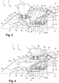
- the ring 14 is arranged around the shaft 15.
- the frustoconical portion 16 of the shaft 15 extends around the cylindrical portion 17 of the shaft 15.
- the frustoconical portion 16 flares from upstream towards downstream.
- the frustoconical portion 16 and the cylindrical portion 17 of the shaft 15 form an axial half-section pin.
- control system 8 of the fourth embodiment is identical to that of the third embodiment.
- the motor architecture of the fourth embodiment notably presents a reduced axial bulk.
Landscapes
- Engineering & Computer Science (AREA)
- Mechanical Engineering (AREA)
- General Engineering & Computer Science (AREA)
- Aviation & Aerospace Engineering (AREA)
- Chemical & Material Sciences (AREA)
- Combustion & Propulsion (AREA)
- Structures Of Non-Positive Displacement Pumps (AREA)
- Other Liquid Machine Or Engine Such As Wave Power Use (AREA)
- Connection Of Motors, Electrical Generators, Mechanical Devices, And The Like (AREA)
Claims (10)
- Turbotriebwerk (1) mit Längsachse (X), umfassend:- einen Rotor (3), der mindestens eine Schaufel mit variabler Feststellposition (5) trägt, wobei der Rotor (3) über ein erstes Lager (6) und ein zweites Lager (7) in Bezug auf eine festsitzende Struktur (4) des Turbotriebwerks (1) in Drehung versetzt wird;- ein Steuersystem der Feststellposition (8) der mindestens einen Schaufel (5), wobei das Steuersystem (8) fest mit dem Rotor (3) verbunden ist und mindestens ein erstes Stellglied (9) umfasst, das durch eine Energie in Bewegung versetzt wird, wobei das Steuersystem (8) axial stromaufwärts des ersten und des zweiten Lagers (6, 7) angeordnet ist;- eine Energieübertragungsvorrichtung (10), die axial zwischen dem ersten Lager (6) und dem zweiten Lager (7) angeordnet ist, wobei die Übertragungsvorrichtung (10) ein festsitzendes Organ (11), das fest mit der festsitzenden Struktur (4) verbunden ist, und ein bewegliches Organ (12), das fest mit dem Rotor (3) verbunden ist, umfasst;dadurch gekennzeichnet, dass der Rotor (3) ringförmig ist und einen zur stromaufwärtigen Seite offenen Innenraum (13) definiert, in dem das Steuersystem (8) platziert ist.
- Turbotriebwerk (1) nach Anspruch 1, dadurch gekennzeichnet, dass der Rotor (3) einen Stützring (14) der mindestens einen Schaufel (5) und eine Welle (15), die einen kegelförmigen Abschnitt (16) und einen zylindrischen Abschnitt (17) aufweist, auf der das erste und das zweite Lager (6, 7) angebracht sind, sowie das bewegliche Organ (12) der Übertragungsvorrichtung (10) umfasst.
- Turbotriebwerk (1) nach einem der vorstehenden Ansprüche, dadurch gekennzeichnet, dass das erste Stellglied (9) ein hydraulisches Stellglied ist, wobei die Übertragungsvorrichtung (10) eine Drehverbindung (33) ist, wobei das Steuersystem (8) einen Mechanismus (31) umfasst, der konfiguriert ist, um die von dem hydraulischen Stellglied eingeleitete Bewegung in eine drehende Bewegung der mindestens einen Schaufel (5) umzuwandeln.
- Turbotriebwerk (1) nach einem der Ansprüche 1 bis 2, dadurch gekennzeichnet, dass das erste Stellglied (9) ein elektrisches Stellglied ist, wobei die Übertragungsvorrichtung (10) ein drehender Transformator (36) ist, wobei das Steuersystem (8) einen Mechanismus (31) umfasst, der konfiguriert ist, um die von dem elektrischen Stellglied eingeleitete Bewegung in eine drehende Bewegung der mindestens einen Schaufel (5) umzuwandeln.
- Turbotriebwerk (1) nach Anspruch 4, dadurch gekennzeichnet, dass das erste Stellglied (9) ein Elektromotor ist, der eine drehende Abtriebswelle (39) umfasst, wobei die mindestens eine Schaufel (5) um eine Achse (Y), die im Wesentlichen senkrecht zur Achse (X) ist, drehbeweglich ist, wobei der Mechanismus (31) eine Kurbel (40) umfasst, die ein erstes Ende, das auf der Achse (Y) zentriert und mit der mindestens einen Schaufel drehend gekoppelt ist, und ein zweites Ende umfasst, das einen Nockenfolger (41) aufweist, der in Bezug auf die Achse (Y) exzentrisch ist, wobei der Nockenfolger (41) mit einer Nocke (42) zusammenwirkt, die sich in der Form einer in einem Ring (43) gefertigten Nut darstellt, wobei der Ring (43) mit der Abtriebswelle (39) des Elektromotors drehend gekoppelt ist.
- Turbotriebwerk (1) nach einem der Ansprüche 1 bis 2, dadurch gekennzeichnet, dass die Übertragungsvorrichtung (10) ein drehender Transformator (36) ist, wobei das erste Stellglied (9) ein Elektromotor ist, der konfiguriert ist, um eine Pumpe (44) eines Hydraulikkreislaufs (45), der fest mit dem Rotor (3) verbunden ist, zu betätigen, wobei der Kreislauf (45) einen mit der Pumpe (44) verbundenen Flüssigkeitsbehälter umfasst, wobei der Kreislauf (45) ein zweites hydraulisches Stellglied (46) umfasst, das durch die Pumpe (44) mit Druckflüssigkeit versorgt wird, wobei das Steuersystem (8) einen Mechanismus (31) umfasst, der konfiguriert ist, um die von dem zweiten Stellglied (46) eingeleitete Bewegung in eine drehende Bewegung der mindestens einen Schaufel (5) umzuwandeln.
- Turbotriebwerk (1) nach Anspruch 6, dadurch gekennzeichnet, dass der Kreislauf (45) einen Akkumulator umfasst, der konfiguriert ist, um die mindestens eine Schaufel (5) insbesondere im Falle eines Ausfalls des drehenden Transformators (36) in Fahnenstellung zu bringen.
- Turbotriebwerk (1) nach einem der vorstehenden Ansprüche, dadurch gekennzeichnet, dass der Rotor (3) in Bezug auf eine ringförmige Stütze (18) der festsitzenden Struktur (4) in Drehung versetzt wird, wobei die Stütze (18) an einer inneren Nabe (21) eines Zwischengehäuses (22) angebracht ist, wobei die Stütze (18) eine kegelförmige stromaufwärtige Wand (23), eine kegelförmige stromabwärtige Wand (24) und eine rohrförmige zylindrische Wand (25) umfasst, in der das erste Lager (6) und das festsitzende Organ (11) der Übertragungsvorrichtung (10) aufgenommen sind, wobei die zylindrische Wand (25) axial zwischen der stromaufwärtigen Wand (23) und der stromabwärtigen Wand (24) angeordnet ist.
- Turbotriebwerk (1) nach Anspruch 8, dadurch gekennzeichnet, dass das erste Lager (6) stromaufwärts des zweiten Lagers (7) angeordnet ist.
- Turbotriebwerk (1) nach einem der vorstehenden Ansprüche, dadurch gekennzeichnet, dass der Rotor (3) mit einem Planetenträger eines Untersetzungsgetriebes (19) drehend gekoppelt ist.
Applications Claiming Priority (2)
| Application Number | Priority Date | Filing Date | Title |
|---|---|---|---|
| FR1859479A FR3087232B1 (fr) | 2018-10-12 | 2018-10-12 | Turbomachine comprenant un rotor portant des pales a calage variable |
| PCT/FR2019/052371 WO2020074817A1 (fr) | 2018-10-12 | 2019-10-07 | Turbomachine comprenant un rotor portant des pales a calage variable |
Publications (2)
| Publication Number | Publication Date |
|---|---|
| EP3864299A1 EP3864299A1 (de) | 2021-08-18 |
| EP3864299B1 true EP3864299B1 (de) | 2024-07-24 |
Family
ID=65443988
Family Applications (2)
| Application Number | Title | Priority Date | Filing Date |
|---|---|---|---|
| EP19817382.5A Active EP3864299B1 (de) | 2018-10-12 | 2019-10-07 | Turbinenmotor mit einem rotor mit schaufeln mit verstellbarer neigung |
| EP19813923.0A Active EP3864298B1 (de) | 2018-10-12 | 2019-10-07 | Turbinenmotor mit einem rotor mit verstellbaren schaufeln |
Family Applications After (1)
| Application Number | Title | Priority Date | Filing Date |
|---|---|---|---|
| EP19813923.0A Active EP3864298B1 (de) | 2018-10-12 | 2019-10-07 | Turbinenmotor mit einem rotor mit verstellbaren schaufeln |
Country Status (5)
| Country | Link |
|---|---|
| US (2) | US11719107B2 (de) |
| EP (2) | EP3864299B1 (de) |
| CN (2) | CN112823245B (de) |
| FR (1) | FR3087232B1 (de) |
| WO (2) | WO2020074817A1 (de) |
Families Citing this family (13)
| Publication number | Priority date | Publication date | Assignee | Title |
|---|---|---|---|---|
| FR3101664B1 (fr) * | 2019-10-02 | 2021-09-03 | Safran Aircraft Engines | Système de commande de calage cyclique de pales |
| FR3120651B1 (fr) | 2021-03-09 | 2023-05-12 | Safran Aircraft Engines | Dispositif de calage de pas de pales pour turbomachine et turbomachine le comportant |
| FR3120913B1 (fr) * | 2021-03-16 | 2023-02-24 | Safran Aircraft Engines | Module de soufflante equipe d’un dispositif de transfert d’huile |
| FR3120915B1 (fr) | 2021-03-16 | 2023-04-14 | Safran Aircraft Engines | Module de soufflante equipe d’un dispositif de transfert d’huile |
| FR3126016B1 (fr) * | 2021-08-04 | 2025-09-19 | Safran Helicopter Engines | Turbopropulseur apte à fournir une fonction d’éolienne de secours et aéronef comportant un tel turbopropulseur |
| FR3127532B1 (fr) | 2021-09-29 | 2023-10-13 | Safran Aircraft Engines | Module pour une turbomachine d’aeronef |
| FR3127523B1 (fr) | 2021-09-29 | 2025-08-15 | Safran Aircraft Engines | Module pour une turbomachine d’aeronef |
| FR3130748B1 (fr) | 2021-12-17 | 2023-11-03 | Safran Aircraft Engines | Ensemble hydraulique pour un moteur d’aeronef |
| FR3130875B1 (fr) * | 2021-12-20 | 2024-08-09 | Safran Aircraft Engines | Module de turbomachine equipe d’aubes a calage variable et d’un dispostif de transfert d’huile |
| FR3130874B1 (fr) * | 2021-12-20 | 2023-11-10 | Safran Aircraft Engines | Module de turbomachine equipe d’un systeme de changement de pas et d’un dispostif de transfert de fluide a emmanchement en aveugle |
| FR3134599B1 (fr) | 2022-04-15 | 2025-05-02 | Safran Aircraft Engines | Module pour une turbomachine d’aeronef |
| FR3160996A1 (fr) * | 2024-04-05 | 2025-10-10 | Safran Aircraft Engines | Rotor de soufflante integrant une pompe de mecanisme de changement de pas |
| FR3160954A1 (fr) * | 2024-04-05 | 2025-10-10 | Safran Aircraft Engines | Mécanisme de changement de pas avec dispositif de verrouillage de pas |
Family Cites Families (19)
| Publication number | Priority date | Publication date | Assignee | Title |
|---|---|---|---|---|
| US2850103A (en) * | 1956-05-14 | 1958-09-02 | United Aircraft Corp | Propeller mounted on engine casing |
| GB1185040A (en) * | 1966-04-12 | 1970-03-18 | Dowty Rotol Ltd | Bladed Rotors |
| GB1294898A (de) * | 1969-12-13 | 1972-11-01 | ||
| US3866415A (en) * | 1974-02-25 | 1975-02-18 | Gen Electric | Fan blade actuator using pressurized air |
| US3912418A (en) * | 1974-10-01 | 1975-10-14 | United Technologies Corp | Lubrication system for a rotor |
| FR2712250B1 (fr) | 1993-11-10 | 1995-12-29 | Hispano Suiza Sa | Procédé et dispositif de commande de variation du pas des pales d'un rotor. |
| US5451141A (en) * | 1993-12-23 | 1995-09-19 | United Technologies Corporation | Propeller pitch change machanism with inductive brake and motor |
| FR2831225B1 (fr) | 2001-10-24 | 2004-01-02 | Snecma Moteurs | Dispositif electrohydraulique de changement de pas d'helice |
| FR2913050B1 (fr) * | 2007-02-28 | 2011-06-17 | Snecma | Turbine haute-pression d'une turbomachine |
| FR2931797B1 (fr) * | 2008-05-29 | 2010-07-30 | Snecma | Systeme simplifie de commande de calage de pale d'une helice d'un turbomoteur pour aeronef |
| US8162611B2 (en) * | 2008-07-15 | 2012-04-24 | Hamilton Sundstrand Corporation | Controllable pitch propeller with electrical power generation |
| FR2980770B1 (fr) * | 2011-10-03 | 2014-06-27 | Snecma | Turbomachine a helice(s) pour aeronef avec systeme pour changer le pas de l'helice. |
| FR3013387B1 (fr) * | 2013-11-20 | 2015-11-20 | Snecma | Support de palier presentant une geometrie facilitant l'evacuation des noyaux de fonderie |
| FR3017164B1 (fr) * | 2014-02-03 | 2016-02-05 | Snecma | Turbomachine a doublet d'helices pour aeronef |
| US9885405B2 (en) * | 2014-05-23 | 2018-02-06 | Valeo Embrayages | Stator assembly of hydrokinetic torque converter with press crimped retainer plates and method for making the same |
| US10533436B2 (en) * | 2015-11-04 | 2020-01-14 | General Electric Company | Centerline-mounted hydraulic pitch change mechanism actuator |
| FR3046407B1 (fr) * | 2016-01-05 | 2022-03-25 | Snecma | Dispositif a verin fixe pour systeme de commande de l'orientation des pales de soufflante d'une turbomachine |
| US10393137B2 (en) * | 2016-02-12 | 2019-08-27 | General Electric Company | Method and system for integrated pitch control mechanism actuator hydraulic fluid transfer |
| FR3050433B1 (fr) * | 2016-04-20 | 2020-08-28 | Snecma | Systeme simplifie d'actionnement de pas pour une helice de turbomachine |
-
2018
- 2018-10-12 FR FR1859479A patent/FR3087232B1/fr not_active Expired - Fee Related
-
2019
- 2019-10-07 CN CN201980066569.9A patent/CN112823245B/zh active Active
- 2019-10-07 EP EP19817382.5A patent/EP3864299B1/de active Active
- 2019-10-07 CN CN201980066540.0A patent/CN112805475B/zh active Active
- 2019-10-07 WO PCT/FR2019/052371 patent/WO2020074817A1/fr not_active Ceased
- 2019-10-07 US US17/283,365 patent/US11719107B2/en active Active
- 2019-10-07 WO PCT/FR2019/052370 patent/WO2020074816A1/fr not_active Ceased
- 2019-10-07 US US17/283,341 patent/US11396821B2/en active Active
- 2019-10-07 EP EP19813923.0A patent/EP3864298B1/de active Active
Also Published As
| Publication number | Publication date |
|---|---|
| EP3864298A1 (de) | 2021-08-18 |
| CN112805475B (zh) | 2024-02-13 |
| US20220003123A1 (en) | 2022-01-06 |
| US11719107B2 (en) | 2023-08-08 |
| US11396821B2 (en) | 2022-07-26 |
| US20210381388A1 (en) | 2021-12-09 |
| EP3864298B1 (de) | 2023-07-19 |
| EP3864299A1 (de) | 2021-08-18 |
| CN112823245A (zh) | 2021-05-18 |
| WO2020074816A1 (fr) | 2020-04-16 |
| CN112805475A (zh) | 2021-05-14 |
| CN112823245B (zh) | 2024-03-08 |
| WO2020074817A1 (fr) | 2020-04-16 |
| FR3087232B1 (fr) | 2021-06-25 |
| FR3087232A1 (fr) | 2020-04-17 |
Similar Documents
| Publication | Publication Date | Title |
|---|---|---|
| EP3864299B1 (de) | Turbinenmotor mit einem rotor mit schaufeln mit verstellbarer neigung | |
| CA2951196A1 (fr) | Turbomachine comprenant un systeme d'entrainement d'un equipement tel qu'un boitier d'accessoires | |
| EP4304932B1 (de) | Blattverstellungsmechanismus für turbomaschine sowie mit diesem mechanismus ausgestattete turbomaschine | |
| FR2993631A1 (fr) | Dispositif de raccordement en aveugle entre des alimentations fluidiques, electriques ou analogues, et un mecanisme de commande recepteur | |
| WO2023247906A1 (fr) | Mecanisme de changement de pas avec verin entourant un palier de transfert de fluide | |
| EP3999730B1 (de) | Planetenuntersetzungsgetriebe für eine turbomaschine | |
| EP3999729B1 (de) | Planetenuntersetzungsgetriebe für eine turbomaschine | |
| EP4380858B1 (de) | Turbine mit verstellbarem anstellwinkel | |
| FR3046402A1 (fr) | Systeme de changement de pas pour turbopropulseur a doublet d'helices contrarotatives amont | |
| EP4408738B1 (de) | Modul für ein flugzeugturbinentriebwerk | |
| FR3021296A1 (fr) | Ensemble de propulsion a doublet d'helices pour aeronef | |
| EP4543751A1 (de) | Neigungsänderungsmechanismus mit neigungsverriegelungsvorrichtung mit einem satellitenrollengewinde | |
| EP3999719A1 (de) | Turbomaschinenmodul mit einem system zum ändern der neigung der schaufeln eines propellers und mit einer vorrichtung zum federn der schaufeln | |
| EP4448382B1 (de) | Hydraulikbaugruppe für ein flugzeugtriebwerk | |
| FR3086001A1 (fr) | Systeme de propulsion d'aeronef a soufflante disposee a une extremite arriere du fuselage | |
| FR3137060A1 (fr) | Mécanisme de changement de pas avec vérin entourant un palier de transfert de fluide | |
| WO2024089375A1 (fr) | Mecanisme de changement de pas avec dispositif de verrouillage de pas en porte-a-faux | |
| WO2023052714A1 (fr) | Module pour une turbomachine d'aeronef | |
| EP4608717A1 (de) | Pitchwechselmechanismus mit betätigungszylinder und pitchverriegelungseinrichtung ausserhalb der kammern des betätigungszylinders | |
| WO2024089377A1 (fr) | Mecanisme de changement de pas a cinematique inversee | |
| FR3126017A1 (fr) | Module de soufflante a pales a calage variable | |
| FR3028835A1 (fr) | Dispositif d'actionnement instrumente pour une turbomachine d'aeronef |
Legal Events
| Date | Code | Title | Description |
|---|---|---|---|
| STAA | Information on the status of an ep patent application or granted ep patent |
Free format text: STATUS: UNKNOWN |
|
| STAA | Information on the status of an ep patent application or granted ep patent |
Free format text: STATUS: THE INTERNATIONAL PUBLICATION HAS BEEN MADE |
|
| PUAI | Public reference made under article 153(3) epc to a published international application that has entered the european phase |
Free format text: ORIGINAL CODE: 0009012 |
|
| STAA | Information on the status of an ep patent application or granted ep patent |
Free format text: STATUS: REQUEST FOR EXAMINATION WAS MADE |
|
| 17P | Request for examination filed |
Effective date: 20210428 |
|
| AK | Designated contracting states |
Kind code of ref document: A1 Designated state(s): AL AT BE BG CH CY CZ DE DK EE ES FI FR GB GR HR HU IE IS IT LI LT LU LV MC MK MT NL NO PL PT RO RS SE SI SK SM TR |
|
| DAV | Request for validation of the european patent (deleted) | ||
| DAX | Request for extension of the european patent (deleted) | ||
| STAA | Information on the status of an ep patent application or granted ep patent |
Free format text: STATUS: EXAMINATION IS IN PROGRESS |
|
| 17Q | First examination report despatched |
Effective date: 20230109 |
|
| GRAP | Despatch of communication of intention to grant a patent |
Free format text: ORIGINAL CODE: EPIDOSNIGR1 |
|
| STAA | Information on the status of an ep patent application or granted ep patent |
Free format text: STATUS: GRANT OF PATENT IS INTENDED |
|
| INTG | Intention to grant announced |
Effective date: 20240405 |
|
| GRAS | Grant fee paid |
Free format text: ORIGINAL CODE: EPIDOSNIGR3 |
|
| GRAA | (expected) grant |
Free format text: ORIGINAL CODE: 0009210 |
|
| STAA | Information on the status of an ep patent application or granted ep patent |
Free format text: STATUS: THE PATENT HAS BEEN GRANTED |
|
| AK | Designated contracting states |
Kind code of ref document: B1 Designated state(s): AL AT BE BG CH CY CZ DE DK EE ES FI FR GB GR HR HU IE IS IT LI LT LU LV MC MK MT NL NO PL PT RO RS SE SI SK SM TR |
|
| REG | Reference to a national code |
Ref country code: GB Ref legal event code: FG4D Free format text: NOT ENGLISH |
|
| REG | Reference to a national code |
Ref country code: CH Ref legal event code: EP |
|
| REG | Reference to a national code |
Ref country code: DE Ref legal event code: R096 Ref document number: 602019055815 Country of ref document: DE |
|
| REG | Reference to a national code |
Ref country code: IE Ref legal event code: FG4D Free format text: LANGUAGE OF EP DOCUMENT: FRENCH |
|
| REG | Reference to a national code |
Ref country code: LT Ref legal event code: MG9D |
|
| REG | Reference to a national code |
Ref country code: NL Ref legal event code: MP Effective date: 20240724 |
|
| PG25 | Lapsed in a contracting state [announced via postgrant information from national office to epo] |
Ref country code: PT Free format text: LAPSE BECAUSE OF FAILURE TO SUBMIT A TRANSLATION OF THE DESCRIPTION OR TO PAY THE FEE WITHIN THE PRESCRIBED TIME-LIMIT Effective date: 20241125 |
|
| REG | Reference to a national code |
Ref country code: AT Ref legal event code: MK05 Ref document number: 1706523 Country of ref document: AT Kind code of ref document: T Effective date: 20240724 |
|
| PG25 | Lapsed in a contracting state [announced via postgrant information from national office to epo] |
Ref country code: NL Free format text: LAPSE BECAUSE OF FAILURE TO SUBMIT A TRANSLATION OF THE DESCRIPTION OR TO PAY THE FEE WITHIN THE PRESCRIBED TIME-LIMIT Effective date: 20240724 |
|
| PG25 | Lapsed in a contracting state [announced via postgrant information from national office to epo] |
Ref country code: PT Free format text: LAPSE BECAUSE OF FAILURE TO SUBMIT A TRANSLATION OF THE DESCRIPTION OR TO PAY THE FEE WITHIN THE PRESCRIBED TIME-LIMIT Effective date: 20241125 Ref country code: NL Free format text: LAPSE BECAUSE OF FAILURE TO SUBMIT A TRANSLATION OF THE DESCRIPTION OR TO PAY THE FEE WITHIN THE PRESCRIBED TIME-LIMIT Effective date: 20240724 |
|
| PG25 | Lapsed in a contracting state [announced via postgrant information from national office to epo] |
Ref country code: NO Free format text: LAPSE BECAUSE OF FAILURE TO SUBMIT A TRANSLATION OF THE DESCRIPTION OR TO PAY THE FEE WITHIN THE PRESCRIBED TIME-LIMIT Effective date: 20241024 |
|
| PG25 | Lapsed in a contracting state [announced via postgrant information from national office to epo] |
Ref country code: FI Free format text: LAPSE BECAUSE OF FAILURE TO SUBMIT A TRANSLATION OF THE DESCRIPTION OR TO PAY THE FEE WITHIN THE PRESCRIBED TIME-LIMIT Effective date: 20240724 Ref country code: PL Free format text: LAPSE BECAUSE OF FAILURE TO SUBMIT A TRANSLATION OF THE DESCRIPTION OR TO PAY THE FEE WITHIN THE PRESCRIBED TIME-LIMIT Effective date: 20240724 Ref country code: GR Free format text: LAPSE BECAUSE OF FAILURE TO SUBMIT A TRANSLATION OF THE DESCRIPTION OR TO PAY THE FEE WITHIN THE PRESCRIBED TIME-LIMIT Effective date: 20241025 |
|
| PG25 | Lapsed in a contracting state [announced via postgrant information from national office to epo] |
Ref country code: BG Free format text: LAPSE BECAUSE OF FAILURE TO SUBMIT A TRANSLATION OF THE DESCRIPTION OR TO PAY THE FEE WITHIN THE PRESCRIBED TIME-LIMIT Effective date: 20240724 |
|
| PG25 | Lapsed in a contracting state [announced via postgrant information from national office to epo] |
Ref country code: LV Free format text: LAPSE BECAUSE OF FAILURE TO SUBMIT A TRANSLATION OF THE DESCRIPTION OR TO PAY THE FEE WITHIN THE PRESCRIBED TIME-LIMIT Effective date: 20240724 |
|
| PG25 | Lapsed in a contracting state [announced via postgrant information from national office to epo] |
Ref country code: IS Free format text: LAPSE BECAUSE OF FAILURE TO SUBMIT A TRANSLATION OF THE DESCRIPTION OR TO PAY THE FEE WITHIN THE PRESCRIBED TIME-LIMIT Effective date: 20241124 Ref country code: AT Free format text: LAPSE BECAUSE OF FAILURE TO SUBMIT A TRANSLATION OF THE DESCRIPTION OR TO PAY THE FEE WITHIN THE PRESCRIBED TIME-LIMIT Effective date: 20240724 |
|
| PG25 | Lapsed in a contracting state [announced via postgrant information from national office to epo] |
Ref country code: HR Free format text: LAPSE BECAUSE OF FAILURE TO SUBMIT A TRANSLATION OF THE DESCRIPTION OR TO PAY THE FEE WITHIN THE PRESCRIBED TIME-LIMIT Effective date: 20240724 |
|
| PG25 | Lapsed in a contracting state [announced via postgrant information from national office to epo] |
Ref country code: RS Free format text: LAPSE BECAUSE OF FAILURE TO SUBMIT A TRANSLATION OF THE DESCRIPTION OR TO PAY THE FEE WITHIN THE PRESCRIBED TIME-LIMIT Effective date: 20241024 Ref country code: ES Free format text: LAPSE BECAUSE OF FAILURE TO SUBMIT A TRANSLATION OF THE DESCRIPTION OR TO PAY THE FEE WITHIN THE PRESCRIBED TIME-LIMIT Effective date: 20240724 |
|
| PG25 | Lapsed in a contracting state [announced via postgrant information from national office to epo] |
Ref country code: RS Free format text: LAPSE BECAUSE OF FAILURE TO SUBMIT A TRANSLATION OF THE DESCRIPTION OR TO PAY THE FEE WITHIN THE PRESCRIBED TIME-LIMIT Effective date: 20241024 Ref country code: PL Free format text: LAPSE BECAUSE OF FAILURE TO SUBMIT A TRANSLATION OF THE DESCRIPTION OR TO PAY THE FEE WITHIN THE PRESCRIBED TIME-LIMIT Effective date: 20240724 Ref country code: NO Free format text: LAPSE BECAUSE OF FAILURE TO SUBMIT A TRANSLATION OF THE DESCRIPTION OR TO PAY THE FEE WITHIN THE PRESCRIBED TIME-LIMIT Effective date: 20241024 Ref country code: LV Free format text: LAPSE BECAUSE OF FAILURE TO SUBMIT A TRANSLATION OF THE DESCRIPTION OR TO PAY THE FEE WITHIN THE PRESCRIBED TIME-LIMIT Effective date: 20240724 Ref country code: IS Free format text: LAPSE BECAUSE OF FAILURE TO SUBMIT A TRANSLATION OF THE DESCRIPTION OR TO PAY THE FEE WITHIN THE PRESCRIBED TIME-LIMIT Effective date: 20241124 Ref country code: HR Free format text: LAPSE BECAUSE OF FAILURE TO SUBMIT A TRANSLATION OF THE DESCRIPTION OR TO PAY THE FEE WITHIN THE PRESCRIBED TIME-LIMIT Effective date: 20240724 Ref country code: GR Free format text: LAPSE BECAUSE OF FAILURE TO SUBMIT A TRANSLATION OF THE DESCRIPTION OR TO PAY THE FEE WITHIN THE PRESCRIBED TIME-LIMIT Effective date: 20241025 Ref country code: FI Free format text: LAPSE BECAUSE OF FAILURE TO SUBMIT A TRANSLATION OF THE DESCRIPTION OR TO PAY THE FEE WITHIN THE PRESCRIBED TIME-LIMIT Effective date: 20240724 Ref country code: ES Free format text: LAPSE BECAUSE OF FAILURE TO SUBMIT A TRANSLATION OF THE DESCRIPTION OR TO PAY THE FEE WITHIN THE PRESCRIBED TIME-LIMIT Effective date: 20240724 Ref country code: BG Free format text: LAPSE BECAUSE OF FAILURE TO SUBMIT A TRANSLATION OF THE DESCRIPTION OR TO PAY THE FEE WITHIN THE PRESCRIBED TIME-LIMIT Effective date: 20240724 Ref country code: AT Free format text: LAPSE BECAUSE OF FAILURE TO SUBMIT A TRANSLATION OF THE DESCRIPTION OR TO PAY THE FEE WITHIN THE PRESCRIBED TIME-LIMIT Effective date: 20240724 |
|
| PG25 | Lapsed in a contracting state [announced via postgrant information from national office to epo] |
Ref country code: RO Free format text: LAPSE BECAUSE OF FAILURE TO SUBMIT A TRANSLATION OF THE DESCRIPTION OR TO PAY THE FEE WITHIN THE PRESCRIBED TIME-LIMIT Effective date: 20240724 Ref country code: SM Free format text: LAPSE BECAUSE OF FAILURE TO SUBMIT A TRANSLATION OF THE DESCRIPTION OR TO PAY THE FEE WITHIN THE PRESCRIBED TIME-LIMIT Effective date: 20240724 Ref country code: DK Free format text: LAPSE BECAUSE OF FAILURE TO SUBMIT A TRANSLATION OF THE DESCRIPTION OR TO PAY THE FEE WITHIN THE PRESCRIBED TIME-LIMIT Effective date: 20240724 |
|
| PG25 | Lapsed in a contracting state [announced via postgrant information from national office to epo] |
Ref country code: EE Free format text: LAPSE BECAUSE OF FAILURE TO SUBMIT A TRANSLATION OF THE DESCRIPTION OR TO PAY THE FEE WITHIN THE PRESCRIBED TIME-LIMIT Effective date: 20240724 |
|
| PG25 | Lapsed in a contracting state [announced via postgrant information from national office to epo] |
Ref country code: CZ Free format text: LAPSE BECAUSE OF FAILURE TO SUBMIT A TRANSLATION OF THE DESCRIPTION OR TO PAY THE FEE WITHIN THE PRESCRIBED TIME-LIMIT Effective date: 20240724 |
|
| REG | Reference to a national code |
Ref country code: DE Ref legal event code: R097 Ref document number: 602019055815 Country of ref document: DE |
|
| PG25 | Lapsed in a contracting state [announced via postgrant information from national office to epo] |
Ref country code: IT Free format text: LAPSE BECAUSE OF FAILURE TO SUBMIT A TRANSLATION OF THE DESCRIPTION OR TO PAY THE FEE WITHIN THE PRESCRIBED TIME-LIMIT Effective date: 20240724 Ref country code: SK Free format text: LAPSE BECAUSE OF FAILURE TO SUBMIT A TRANSLATION OF THE DESCRIPTION OR TO PAY THE FEE WITHIN THE PRESCRIBED TIME-LIMIT Effective date: 20240724 |
|
| PLBE | No opposition filed within time limit |
Free format text: ORIGINAL CODE: 0009261 |
|
| STAA | Information on the status of an ep patent application or granted ep patent |
Free format text: STATUS: NO OPPOSITION FILED WITHIN TIME LIMIT |
|
| REG | Reference to a national code |
Ref country code: CH Ref legal event code: PL |
|
| 26N | No opposition filed |
Effective date: 20250425 |
|
| PG25 | Lapsed in a contracting state [announced via postgrant information from national office to epo] |
Ref country code: MC Free format text: LAPSE BECAUSE OF FAILURE TO SUBMIT A TRANSLATION OF THE DESCRIPTION OR TO PAY THE FEE WITHIN THE PRESCRIBED TIME-LIMIT Effective date: 20240724 |
|
| PG25 | Lapsed in a contracting state [announced via postgrant information from national office to epo] |
Ref country code: LU Free format text: LAPSE BECAUSE OF NON-PAYMENT OF DUE FEES Effective date: 20241007 Ref country code: BE Free format text: LAPSE BECAUSE OF NON-PAYMENT OF DUE FEES Effective date: 20241031 |
|
| PG25 | Lapsed in a contracting state [announced via postgrant information from national office to epo] |
Ref country code: CH Free format text: LAPSE BECAUSE OF NON-PAYMENT OF DUE FEES Effective date: 20241031 |
|
| REG | Reference to a national code |
Ref country code: BE Ref legal event code: MM Effective date: 20241031 |
|
| PG25 | Lapsed in a contracting state [announced via postgrant information from national office to epo] |
Ref country code: SE Free format text: LAPSE BECAUSE OF FAILURE TO SUBMIT A TRANSLATION OF THE DESCRIPTION OR TO PAY THE FEE WITHIN THE PRESCRIBED TIME-LIMIT Effective date: 20240724 |
|
| PG25 | Lapsed in a contracting state [announced via postgrant information from national office to epo] |
Ref country code: IE Free format text: LAPSE BECAUSE OF NON-PAYMENT OF DUE FEES Effective date: 20241007 |
|
| PGFP | Annual fee paid to national office [announced via postgrant information from national office to epo] |
Ref country code: DE Payment date: 20251020 Year of fee payment: 7 |
|
| PGFP | Annual fee paid to national office [announced via postgrant information from national office to epo] |
Ref country code: GB Payment date: 20251029 Year of fee payment: 7 |
|
| PGFP | Annual fee paid to national office [announced via postgrant information from national office to epo] |
Ref country code: FR Payment date: 20251022 Year of fee payment: 7 |
|
| PG25 | Lapsed in a contracting state [announced via postgrant information from national office to epo] |
Ref country code: CY Free format text: LAPSE BECAUSE OF FAILURE TO SUBMIT A TRANSLATION OF THE DESCRIPTION OR TO PAY THE FEE WITHIN THE PRESCRIBED TIME-LIMIT; INVALID AB INITIO Effective date: 20191007 |