EP3863759B1 - Cavitation reactor and manufacturing method thereof - Google Patents
Cavitation reactor and manufacturing method thereof Download PDFInfo
- Publication number
- EP3863759B1 EP3863759B1 EP19798395.0A EP19798395A EP3863759B1 EP 3863759 B1 EP3863759 B1 EP 3863759B1 EP 19798395 A EP19798395 A EP 19798395A EP 3863759 B1 EP3863759 B1 EP 3863759B1
- Authority
- EP
- European Patent Office
- Prior art keywords
- stator
- centrifugal stage
- gap
- opening
- wall
- Prior art date
- Legal status (The legal status is an assumption and is not a legal conclusion. Google has not performed a legal analysis and makes no representation as to the accuracy of the status listed.)
- Active
Links
- 238000004519 manufacturing process Methods 0.000 title claims description 8
- 239000012530 fluid Substances 0.000 claims description 88
- 230000002093 peripheral effect Effects 0.000 claims description 43
- 238000005192 partition Methods 0.000 claims description 17
- 238000004891 communication Methods 0.000 claims description 11
- 238000009825 accumulation Methods 0.000 claims description 2
- 230000001105 regulatory effect Effects 0.000 claims 1
- 239000007788 liquid Substances 0.000 description 8
- 239000000203 mixture Substances 0.000 description 6
- 238000005086 pumping Methods 0.000 description 6
- 230000015572 biosynthetic process Effects 0.000 description 4
- 239000007787 solid Substances 0.000 description 4
- 238000010276 construction Methods 0.000 description 3
- 239000007789 gas Substances 0.000 description 3
- 230000008859 change Effects 0.000 description 2
- 239000002245 particle Substances 0.000 description 2
- 230000009467 reduction Effects 0.000 description 2
- 230000035939 shock Effects 0.000 description 2
- 230000001154 acute effect Effects 0.000 description 1
- 239000012141 concentrate Substances 0.000 description 1
- 230000001066 destructive effect Effects 0.000 description 1
- 230000000694 effects Effects 0.000 description 1
- 239000000839 emulsion Substances 0.000 description 1
- 238000000605 extraction Methods 0.000 description 1
- 238000007667 floating Methods 0.000 description 1
- 238000010438 heat treatment Methods 0.000 description 1
- 238000000265 homogenisation Methods 0.000 description 1
- 238000009434 installation Methods 0.000 description 1
- 238000000034 method Methods 0.000 description 1
- 238000002156 mixing Methods 0.000 description 1
- 238000009928 pasteurization Methods 0.000 description 1
- 230000008569 process Effects 0.000 description 1
- 230000003068 static effect Effects 0.000 description 1
- 238000011144 upstream manufacturing Methods 0.000 description 1
Images


Classifications
-
- B—PERFORMING OPERATIONS; TRANSPORTING
- B01—PHYSICAL OR CHEMICAL PROCESSES OR APPARATUS IN GENERAL
- B01J—CHEMICAL OR PHYSICAL PROCESSES, e.g. CATALYSIS OR COLLOID CHEMISTRY; THEIR RELEVANT APPARATUS
- B01J19/00—Chemical, physical or physico-chemical processes in general; Their relevant apparatus
- B01J19/008—Processes for carrying out reactions under cavitation conditions
-
- B—PERFORMING OPERATIONS; TRANSPORTING
- B01—PHYSICAL OR CHEMICAL PROCESSES OR APPARATUS IN GENERAL
- B01F—MIXING, e.g. DISSOLVING, EMULSIFYING OR DISPERSING
- B01F25/00—Flow mixers; Mixers for falling materials, e.g. solid particles
- B01F25/60—Pump mixers, i.e. mixing within a pump
- B01F25/64—Pump mixers, i.e. mixing within a pump of the centrifugal-pump type, i.e. turbo-mixers
- B01F25/642—Pump mixers, i.e. mixing within a pump of the centrifugal-pump type, i.e. turbo-mixers consisting of a stator-rotor system with intermeshing teeth or cages
-
- B—PERFORMING OPERATIONS; TRANSPORTING
- B01—PHYSICAL OR CHEMICAL PROCESSES OR APPARATUS IN GENERAL
- B01F—MIXING, e.g. DISSOLVING, EMULSIFYING OR DISPERSING
- B01F27/00—Mixers with rotary stirring devices in fixed receptacles; Kneaders
- B01F27/80—Mixers with rotary stirring devices in fixed receptacles; Kneaders with stirrers rotating about a substantially vertical axis
- B01F27/81—Mixers with rotary stirring devices in fixed receptacles; Kneaders with stirrers rotating about a substantially vertical axis the stirrers having central axial inflow and substantially radial outflow
- B01F27/811—Mixers with rotary stirring devices in fixed receptacles; Kneaders with stirrers rotating about a substantially vertical axis the stirrers having central axial inflow and substantially radial outflow with the inflow from one side only, e.g. stirrers placed on the bottom of the receptacle, or used as a bottom discharge pump
- B01F27/8111—Mixers with rotary stirring devices in fixed receptacles; Kneaders with stirrers rotating about a substantially vertical axis the stirrers having central axial inflow and substantially radial outflow with the inflow from one side only, e.g. stirrers placed on the bottom of the receptacle, or used as a bottom discharge pump the stirrers co-operating with stationary guiding elements, e.g. surrounding stators or intermeshing stators
-
- B—PERFORMING OPERATIONS; TRANSPORTING
- B01—PHYSICAL OR CHEMICAL PROCESSES OR APPARATUS IN GENERAL
- B01J—CHEMICAL OR PHYSICAL PROCESSES, e.g. CATALYSIS OR COLLOID CHEMISTRY; THEIR RELEVANT APPARATUS
- B01J19/00—Chemical, physical or physico-chemical processes in general; Their relevant apparatus
- B01J19/18—Stationary reactors having moving elements inside
- B01J19/1806—Stationary reactors having moving elements inside resulting in a turbulent flow of the reactants, such as in centrifugal-type reactors, or having a high Reynolds-number
-
- B—PERFORMING OPERATIONS; TRANSPORTING
- B01—PHYSICAL OR CHEMICAL PROCESSES OR APPARATUS IN GENERAL
- B01J—CHEMICAL OR PHYSICAL PROCESSES, e.g. CATALYSIS OR COLLOID CHEMISTRY; THEIR RELEVANT APPARATUS
- B01J19/00—Chemical, physical or physico-chemical processes in general; Their relevant apparatus
- B01J19/18—Stationary reactors having moving elements inside
- B01J19/1812—Tubular reactors
-
- B—PERFORMING OPERATIONS; TRANSPORTING
- B01—PHYSICAL OR CHEMICAL PROCESSES OR APPARATUS IN GENERAL
- B01J—CHEMICAL OR PHYSICAL PROCESSES, e.g. CATALYSIS OR COLLOID CHEMISTRY; THEIR RELEVANT APPARATUS
- B01J2219/00—Chemical, physical or physico-chemical processes in general; Their relevant apparatus
- B01J2219/19—Details relating to the geometry of the reactor
- B01J2219/194—Details relating to the geometry of the reactor round
- B01J2219/1941—Details relating to the geometry of the reactor round circular or disk-shaped
- B01J2219/1943—Details relating to the geometry of the reactor round circular or disk-shaped cylindrical
Definitions
- the present invention finds application in the field of cavitation reactors, which use cavitation to process fluids, including for instance mixtures of liquids, mixtures of liquids and solids or liquids and gases, to improve homogeneity of the fluids that flow out of the reactor, or to reduce the size of the solid particles or gas bubbles dispersed in a liquid.
- the invention relates to an effective cavitation reactor having a simplified construction, and a method of manufacturing such reactor.
- Cavitation occurs when a fluid that flows in a duct undergoes significant pressure changes, e.g. due to sudden changes in the speed or direction of the fluid.
- the equilibrium vapor pressure of the fluid may exceed the internal pressure of the fluid, thereby leading to the formation of vapor bubbles, especially in the areas in which the liquid is exposed to high tensile forces.
- the fluid pressure increases again, for example because the fluid passes beyond the minimum pressure point as it enters a pump, the bubbles implode, thereby generating heat and ultrasonic hydrodynamic shock waves, which are likely to cause significant damage to pump parts.
- cavitation has a destructive effect and hence pumps and hydraulic systems are commonly designed to avoid bubble formation, by maintaining the fluid pressure always above a threshold value and avoiding sudden pressure changes that expose the fluid to tensions directed toward higher pressure areas.
- cavitation may be controlled for using the shock waves and the heat generated thereby on a fluid to be processed, without causing damage to the equipment in which it occurs.
- Certain examples of useful applications of controlled cavitation include mixing, homogenization, heating, pasteurization, floating, emulsion, extraction, reaction and particulate or molecular reduction, for fluids such as mixtures of different liquids, mixtures of liquids and solid particles, or mixtures of liquids and gases. In order to avoid damage to equipment, cavitation must occur away from equipment parts, in the midst of the fluid.
- cavitator or cavitation reactor
- This reactor comprises a stator and a rotor, the latter being housed in a cylindrical cavity of the stator.
- the fluid is introduced into the cavity, is driven by the rotary motion of the rotor, flows around it, and is ejected out of the cavity.
- the rotor has a frustoconical shape and its lateral surface has blind holes formed therein, which contribute to the formation and implosion of bubbles.
- An object of the present invention is to provide a cavitation reactor having a simplified construction, thereby affording a reduction of manufacturing costs.
- a further object of the invention is to provide a cavitation reactor having high efficiency.
- a cavitation reactor and a method of manufacturing a cavitation reactor as defined in any of the accompanying claims.
- the applicant has surprisingly found that a known centrifugal pump with closed impeller may be modified at a low cost to obtain a cavitation reactor that can be usefully employed without causing significant damage to the pump/reactor, or even without causing any damage at all thereto.
- the cavitation reactor of the invention like a centrifugal pump, comprises a stator and a rotor, having a centrifugal stage accommodated in a chamber inside the stator.
- the fluid can enter and exit the chamber through first and second openings of the stator.
- the first opening forms a guide for the longitudinal flow of the fluid, like the fluid inlet openings of the known pumps.
- the centrifugal stage comprises two walls arranged transverse to the direction of the rotation axis of the rotor. A gap is formed between the two walls, and is divided into compartments by circumferentially spaced partitions, consisting for example of the blades of a centrifugal pump. The gap is in fluid communication with the stator chamber, external to the centrifugal stage, at a peripheral portion of the centrifugal stage.
- a differential pressure is obtained between the fluid outside the gap, which has a flow velocity in the stator as it is rotatably driven by the centrifugal stage, and the fluid inside the gap, which is static with respect to the centrifugal stage that contains it. Therefore, the fluid is exposed to a tension that causes the desired cavitation.
- cavitation tends to concentrate in the space between two partitions, away from them, where fluid has a lower friction, thereby avoiding damage to the centrifugal stage.
- the compartments of the gap communicate with each other at the central portion of the centrifugal stage. Therefore, the fluid in this region is exposed to opposite tensile forces directed out of the centrifugal stage, which further helps cavitation to occur away from the reactor parts to be preserved.
- This reactor may be formed from a suitable centrifugal pump, using well-established constructions which are optimized in terms of manufacturing costs, by closing the central opening for access to the gap.
- the pumping capability is significantly reduced as a result of such change, whereby the main application becomes cavitation.
- cavitation reactor of the invention may be used both with fluid flowing from the longitudinally guiding first opening toward the second opening, and with fluid flowing from the second opening to the first opening, unlike centrifugal pumps which only afford a one-way flow.
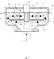
- a cavitation reactor according to one embodiment of the invention is generally designated by numeral 1.
- the reactor 1 comprises a stator 2 and a rotor 3 rotatably connected to the stator 2.
- the stator 2 delimits a chamber 21 which at least partially receives the rotor 3. More in detail, the chamber 21 of the stator 2 is delimited by a front wall 22, a rear wall 23 and a peripheral wall 24 of the stator 2.
- the front wall 22 and rear wall 23 are spaced apart in a longitudinal direction X-X.
- the peripheral wall 24 connects the front wall 22 and the rear wall 23, and is preferably formed as a centrifugal or cylindrical volute.
- the stator 2 has a first opening 25 and a second opening 26 for a fluid to be introduced into the chamber 21 and ejected from the chamber 21.
- the first opening 25 may act as a fluid inlet and the second opening 26 may act as a fluid outlet or conversely the first opening 25 may act as a fluid outlet and the second opening 26 may act as a fluid inlet.
- the first opening 25 has a guiding portion 27 whose shape is intended to guide the fluid flow in the longitudinal direction X-X.
- the first opening 25 is formed in the front wall 22 of the stator 2.
- the first opening 25 may have a channel, not necessarily straight, associated therewith and terminating toward the interior of the chamber 21, at the guiding portion 27.
- the second opening 26 is formed in the peripheral wall 24 of the stator 2 to allow fluid to flow in a direction perpendicular to the longitudinal direction X-X, for example in a radial direction R-R that extends away from a longitudinal center axis of the stator 2. Nevertheless, embodiments may be also provided in which the second opening 26 is formed in the rear wall 23 of the stator 2.
- the rotor 3 comprises a drive shaft 31 which mainly extends in the longitudinal direction X-X.
- the drive shaft 31 is connected to the stator 2 and is adapted to rotate relative to the stator 2 about a rotation axis A-A, which extends in the longitudinal direction X-X and preferably coincides with the longitudinal center axis of the stator 2.
- the drive shaft 31 may be adapted for connection with an electric motor (not shown), either inside or outside the chamber 21 of the stator 2, to rotatably drive the rotor 3 relative to the stator 2.
- the rotor 3 comprises at least one centrifugal stage 4 fixed to the drive shaft 31. Therefore, the centrifugal stage 4 is adapted to rotate relative to the stator 2 together with the drive shaft 31, about the rotation axis A-A.
- the rotor 3 may comprise a plurality of centrifugal stages 4, fixed to the drive shaft 31 and spaced apart in the longitudinal direction X-X, like in known multistage centrifugal pumps.
- the characteristics of a single centrifugal stage 4 will be first described, but they shall be understood to apply to all the stages 4, unless otherwise stated.
- the following characteristics preferably apply at least to the centrifugal stage 4 that is closest to the first opening 25 of the stator 2, i.e. closest to the front wall 22 of the stator 2.
- the centrifugal stage 4 is accommodated in the chamber 21 of the stator 2, and is surrounded by the peripheral wall 24 the stator 2.
- the chamber 21 of the stator 2 has a tubular region 28 which radially surrounds the entire centrifugal stage 4 and is defined between the centrifugal stage 4 and the peripheral wall 24 of the stator 2.
- the tubular region 28 also surrounds the rotation axis A-A and preferably extends longitudinally from the front wall 22 to the rear wall 23 of the stator 2.
- the guiding portion 27 of the first opening 25 of the stator 2 faces the centrifugal stage 4 in the longitudinal direction X-X and more in detail the rotation axis A-A extends through the guiding portion 27.
- the centrifugal stage 4 comprises a first wall 41 and a second wall 42.
- the first and second walls 41, 42 are spaced apart in the longitudinal direction X-X to define a gap 43 therebetween.
- the first wall 41 is proximal to the first opening 25 of the stator 30 and the second wall 42 is distal from the first opening 25. In other words, the first wall 41 is disposed between the second wall 42 and the first opening 25. More in detail, each of the first and second walls 41, 42 has an inner surface 41a, 42a and an outer surface 41b, 42b. The inner surfaces 41a, 42a of the first and second walls 41, 42 face each other and face the gap 43.
- the gap 43 is a recess formed in the centrifugal stage 4 between the first and second walls 41, 42.
- the gap 43 is delimited in the longitudinal direction X-X by the inner surfaces 41a, 42a of the first and second walls 41, 42.
- the gap 43 radially extends up to the tubular region 28 of the chamber 2.
- the outer surface 41b of the first wall 41 is opposite to the corresponding inner surface 41a and faces the first opening 25 of the stator 2.
- the outer surface 42b of the second wall 42 is opposite to the corresponding inner surface 42a, but faces away from the first opening 25 of the stator 2.
- the first and second walls 41, 42 are arranged transverse to the longitudinal direction X-X and the same applies to their respective inner and outer surfaces 41a, 41b, 42a, 42b. Furthermore, the first and second walls 41, 42 radially project out of the drive shaft 31.
- the first and second walls 41, 42 are radially extending walls. Therefore, the rotor 3 is a radial rotor, in a similar manner as what is generally known for radial impellers of certain centrifugal pumps.
- the first and second walls 41, 42 may be shaped as disks or rings, with the rotation axis A-A at the center, and they may be arranged perpendicular to the longitudinal direction X-X. Accordingly, the gap 43 mainly extends substantially in the radial direction R-R.
- the first and second walls 41, 42 do not necessarily have a planar shape like that schematically shown in the figures. Therefore, in other embodiments, the first and second walls 41, 42 may also have three-dimensional shapes adapted to define a conical or funnel-shaped rotor 3, like the conical impellers of known centrifugal pumps. In other words, in these walls a central portion, located at a central portion 45 of the centrifugal stage 4 close to the rotation axis A-A, projects toward the first opening 25 of the stator 2 with respect to a peripheral portion of the wall, located at a peripheral portion 46 of the centrifugal stage 4 spaced apart from the rotation axis A-A.
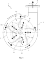
- the centrifugal stage 4 comprises a plurality of partitions 44 arranged in the gap 43.
- the partitions 44 may be shaped as blades of a centrifugal pump, and may therefore have straight or curved profiles, thereby defining acute or grave angles with a circumferential direction C-C that extends about the rotation axis A-A, oriented in the rotation direction of the rotor 3. Nevertheless, it shall be noted the controlled cavitation effect may be obtained in both possible directions of rotation of the rotor 3 about the rotation axis A-A.
- Each partition 44 extends between an inner end 44a, close to the rotation axis A-A, and a peripheral end 44b, spaced apart from the rotation axis A-A. Moreover, the partitions 44 are circumferentially spaced apart about the rotation axis A-A. Therefore, the partitions 44 divide the gap 43 into a plurality of compartments 47 which extend between the central portion 45 of the centrifugal stage 4 and the peripheral portion 46 of the centrifugal stage 4.
- the partitions 44 are designed to rotatably drive the fluid in the gap 43 when the drive shaft 31 rotates relative to the stator 2. This will create a pressure difference between the fluid in the gap 43 at the central portion 45 of the centrifugal stage 4, and the fluid at the peripheral portion 45 of the centrifugal stage 4. This pressure difference caused by centrifugal rotation forces tends to cause the fluid to flow through the compartments 47 from the central portion 45 to the peripheral portion 46 of the centrifugal stage 4. In other words, the pressure at the central portion 45 is lower than that at the peripheral portion 46.
- the gap 43, and particularly the compartments 47, are in fluid communication with the tubular region 28 of the chamber 21 of the stator 2 at the peripheral portion 46 of the centrifugal stage 4.
- a free peripheral edge of the first wall 41 is spaced apart from a free peripheral edge of the second wall 42, preferably in the longitudinal direction X-X. Therefore the fluid in the chamber 21 may flow in and out of the gap 43 between the free peripheral edges of the first and second walls 41, 42.
- the first wall 41 is closed at the central portion 45 of the centrifugal stage 4 thereby preventing the flow of fluid between the first opening 25 and the peripheral portion 46 of the centrifugal stage 4 through the gap 47, namely through the compartments 47 thereof. More in detail, at the central portion 45 fluid communication is prevented between the chamber 21 of the stator 2, outside the centrifugal stage 4, and the gap 43. Furthermore, in the preferred embodiment, the gap 43 is in fluid communication with the rest of the chamber 21, namely with the tubular region 28 of the chamber 21, only at the peripheral portion 46 of the centrifugal stage 4, between the free peripheral edges of the first and second walls 41, 42.
- the second wall 42 is likewise closed at the central portion 45 of the centrifugal stage 4 thereby preventing the flow of fluid between the second opening 26 and the peripheral portion 46 of the centrifugal stage 4 through the gap 47.
- the first wall 41 is closed by a closure member 48 of the centrifugal stage 4, as shown for example in Figures 2-4 . More in detail, the first wall 41 of the centrifugal stage 4 has a central opening 49 at the central portion 45 of the centrifugal stage 4.
- the closure member 48 is fixed to the first walls 41, preferably in a removable manner, to close the central opening 49.
- central opening 49 When free of closing members 48, such central opening 49 may be adapted to act as a fluid intake for the centrifugal stage 4, like in known centrifugal pumps. With a clear central opening 49, the fluid would access the chamber 21, for instance, through the first opening 25, would be drawn into the gap 43 through the central opening 49 due to the aforementioned pressure difference, would later flow in the gap 43 toward the peripheral portion 46 of the centrifugal stage 4, and would be ejected out of the gap 43 into the tubular region 28 of the chamber 21 to reach the second opening 26.
- the closure member 48 occludes this fluid path.
- the fluid will not continuously flow in the radial direction in the gap 43, and only a fluid mix will be provided between the interior of the gap 43 and the tubular region 28 of the chamber 21, outside the gap 43, at the peripheral portion 46 of the centrifugal stage 4.
- the embodiment with the central opening 49 may be obtained from a known centrifugal pump (not shown), in particular from a centrifugal pump with closed impeller (or rotor), which may exhibit substantially all the features as discussed heretofore, excepting the fact that the first wall 41 of the centrifugal stage 4 is closed at the central portion 45.
- a closure member 48 shall be simply fixed to the first wall 41 to close its central opening 49.
- the first wall 41 may have no central openings 49 and be formed, for example, like a solid disk or a funnel having the smaller mouth closed. This may be deemed to be equivalent to the formation of a closure member 48 of one piece with the first wall 41. Therefore, this embodiment does not require changes to be made to a known centrifugal pump after fabrication, but may possibly require a design change, before fabrication, with still low costs.
- the first wall 41 of the centrifugal stage 4 is spaced apart from the front wall 22 of the stator 2. Furthermore, the peripheral portion 46 of the centrifugal stage 4 is spaced apart from the peripheral wall 24 of the stator 2. Relatively small distances are anyway acceptable, as long as they are sufficient for the passage of fluid as described below.
- the fluid flows through the first opening 25, it flows between the first wall 41 of the centrifugal stage 4 and the front wall 22 of the stator 2, in a substantially radial direction R-R, then it flows into the tubular region 28, i.e. between the peripheral portion 46 of the centrifugal stage 4 and the peripheral wall 24 of the stator 4, in a substantially longitudinal direction X-X and preferably with circumferential components due to the rotation of the rotor 3, and finally it flows through the second opening 26.
- a fluid flow is also admitted in the same parts of the cavitation reactor 1 in the direction opposite to the above.
- the compartments 47 of the gap 43 are in fluid communication with each other at the central portion 45 of the centrifugal stage 4.
- the inner ends 44a of two contiguous partitions 44 define a free passage therebetween for the fluid, from one compartment 47 arranged between the two partitions 44 to the rest of the compartments 44.
- the fluid in the gap 43 at the central portion 45 of the centrifugal stage 4 is exposed to opposite tensile forces, generally referenced with the double-headed arrows T, directed toward the peripheral portion 46 of the centrifugal stage 4, which facilitate cavitation.
- fluid communication between the compartments 47 of the gap 43, at the central portion 45 of the centrifugal stage 4 is prevented, for example by the closure member 48.
- the closure member 48 contacts the inner ends 44a of the partitions 44, and more in detail the closure member 48 is shaped to occlude the space between the inner ends 44a of pairs of contiguous partitions 44. Cavitation is anyway obtained due to the pressure difference between the central portion 45 and the peripheral portion 46 of the centrifugal stage 4. Accordingly, the fluid is exposed to a one-way tensile force.
- the Applicant found that the operation of the cavitation reactor 1 requires the rotor 3 to be entirely immersed in the fluid. In particular, it is worthwhile to ensure air to be expelled from the gap 43 should be.
- pressure-regulating members are preferably provided, which are configured to maintain fluid pressure in the chamber 21 above a threshold value which is adapted to prevent air accumulation in the gap 43, especially at the central portion 45 of the centrifugal stage 4.
- pressure regulation may be carried out by parts of the hydraulic system that are outside the reactor 1, for example one or more pumps or valves of the hydraulic system, or otherwise the pressure-regulating members may be provided separate from the reactor 1, or may also be omitted, depending on the structural and operation features of the hydraulic system.
- the rotor 3 may comprise one or more centrifugal stages 4, fixed to the drive shaft 31 and spaced apart in the longitudinal direction X-X, like in known multistage centrifugal pumps.
- the centrifugal stages 4 may be all accommodated in the same chamber 21 of the stator 2, or in distinct chambers 21 of the stator 2.
- This may be provided for the fluid to undergo stronger cavitation, or in view of providing a cavitation reactor 1 that also has pumping functions, in addition to cavitation capabilities.
- a single monolithic device may be adapted to accomplish controlled cavitation and conventional pumping tasks at the same time.
- the rotor 3 comprises centrifugal stages 4 of two types, i.e. at least one first centrifugal stage 4 for cavitation, incorporating the features as discussed heretofore, and at least one second centrifugal stage for pumping (not shown).
- Each second centrifugal stage may include some of the features as set forth above, but not the features concerning closure of the first wall 41.
- the first wall 41 has a clear central opening 49 at the central portion 45 of the stage 4.
- the second centrifugal stage is configured to pump the fluid from the clear central opening 49 to its peripheral portion 46 through its gap 43, along the compartments 47. Therefore, pumping centrifugal stages differ from cavitation centrifugal stages 4 in that they have a clear central opening 49 for fluid to access the gap 43 and in that they do not have their first wall 41 closed by its own design or due to the provision of a closure member 48 at the central, not clear, opening 49.
- pumping centrifugal stages are arranged upstream the cavitation centrifugal stages 4, for a maximum fluid pressure to be provided in cavitation stages.
- the first centrifugal stage 4 is distal from the first opening 25 of the stator 2
- the second centrifugal stage is proximal to the first opening 25 of the stator 2, i.e. the first centrifugal stage 4 is arranged between the second centrifugal stage and the first opening 25 of the stator 2.
Description
- The present invention finds application in the field of cavitation reactors, which use cavitation to process fluids, including for instance mixtures of liquids, mixtures of liquids and solids or liquids and gases, to improve homogeneity of the fluids that flow out of the reactor, or to reduce the size of the solid particles or gas bubbles dispersed in a liquid. In particular, the invention relates to an effective cavitation reactor having a simplified construction, and a method of manufacturing such reactor.
- Cavitation occurs when a fluid that flows in a duct undergoes significant pressure changes, e.g. due to sudden changes in the speed or direction of the fluid. At the minimum-pressure locations of the duct, the equilibrium vapor pressure of the fluid may exceed the internal pressure of the fluid, thereby leading to the formation of vapor bubbles, especially in the areas in which the liquid is exposed to high tensile forces. When the fluid pressure increases again, for example because the fluid passes beyond the minimum pressure point as it enters a pump, the bubbles implode, thereby generating heat and ultrasonic hydrodynamic shock waves, which are likely to cause significant damage to pump parts.
- In this case cavitation has a destructive effect and hence pumps and hydraulic systems are commonly designed to avoid bubble formation, by maintaining the fluid pressure always above a threshold value and avoiding sudden pressure changes that expose the fluid to tensions directed toward higher pressure areas.
- In other contexts, cavitation may be controlled for using the shock waves and the heat generated thereby on a fluid to be processed, without causing damage to the equipment in which it occurs. Certain examples of useful applications of controlled cavitation include mixing, homogenization, heating, pasteurization, floating, emulsion, extraction, reaction and particulate or molecular reduction, for fluids such as mixtures of different liquids, mixtures of liquids and solid particles, or mixtures of liquids and gases. In order to avoid damage to equipment, cavitation must occur away from equipment parts, in the midst of the fluid.
- One example of cavitator, or cavitation reactor, is disclosed in patent application
EP 3278868 , by the Applicant hereof. This reactor comprises a stator and a rotor, the latter being housed in a cylindrical cavity of the stator. The fluid is introduced into the cavity, is driven by the rotary motion of the rotor, flows around it, and is ejected out of the cavity. The rotor has a frustoconical shape and its lateral surface has blind holes formed therein, which contribute to the formation and implosion of bubbles. - Other prior art cavitation reactors include cylindrical rotors, which also have blind holes on their lateral surface. Examples of such reactors are disclosed in
US 7,354,227 ,US 2009184056 andDE 2016182903 . - An object of the present invention is to provide a cavitation reactor having a simplified construction, thereby affording a reduction of manufacturing costs. A further object of the invention is to provide a cavitation reactor having high efficiency.
- These and other objects are fulfilled by a cavitation reactor and a method of manufacturing a cavitation reactor as defined in any of the accompanying claims. In particular, the applicant has surprisingly found that a known centrifugal pump with closed impeller may be modified at a low cost to obtain a cavitation reactor that can be usefully employed without causing significant damage to the pump/reactor, or even without causing any damage at all thereto.
- The cavitation reactor of the invention, like a centrifugal pump, comprises a stator and a rotor, having a centrifugal stage accommodated in a chamber inside the stator. The fluid can enter and exit the chamber through first and second openings of the stator. In particular, the first opening forms a guide for the longitudinal flow of the fluid, like the fluid inlet openings of the known pumps. The centrifugal stage comprises two walls arranged transverse to the direction of the rotation axis of the rotor. A gap is formed between the two walls, and is divided into compartments by circumferentially spaced partitions, consisting for example of the blades of a centrifugal pump. The gap is in fluid communication with the stator chamber, external to the centrifugal stage, at a peripheral portion of the centrifugal stage.
- In prior art centrifugal pumps, fluid is known to flow through the gap, after entering it though an opening located centrally in one of the two walls that delimit the gap, in particular the wall that is closer to the first opening, through which the fluid is designed to enter, and then to exit the gap at the peripheral portion of the centrifugal stage. Unlike the prior art, according to the invention this wall is closed at its central portion.
- Therefore, while fluid is anyway present in the gap, it is not forced to enter the gap to flow between the first opening and the second opening of the stator, but may flow, for example, around the centrifugal stage.
- Advantageously, a differential pressure is obtained between the fluid outside the gap, which has a flow velocity in the stator as it is rotatably driven by the centrifugal stage, and the fluid inside the gap, which is static with respect to the centrifugal stage that contains it. Therefore, the fluid is exposed to a tension that causes the desired cavitation. The Applicant also found that cavitation tends to concentrate in the space between two partitions, away from them, where fluid has a lower friction, thereby avoiding damage to the centrifugal stage.
- In a preferred embodiment, the compartments of the gap communicate with each other at the central portion of the centrifugal stage. Therefore, the fluid in this region is exposed to opposite tensile forces directed out of the centrifugal stage, which further helps cavitation to occur away from the reactor parts to be preserved.
- This reactor may be formed from a suitable centrifugal pump, using well-established constructions which are optimized in terms of manufacturing costs, by closing the central opening for access to the gap. Of course, the pumping capability is significantly reduced as a result of such change, whereby the main application becomes cavitation.
- It shall be noted that the cavitation reactor of the invention may be used both with fluid flowing from the longitudinally guiding first opening toward the second opening, and with fluid flowing from the second opening to the first opening, unlike centrifugal pumps which only afford a one-way flow.
- Further characteristics and advantages of the present invention will result more clearly from the illustrative, non-limiting description of a cavitation reactor as shown in the annexed drawings, in which:
-
Figure 1 shows a lateral sectional view of a cavitation reactor according to a first embodiment of the invention, -
Figure 2 shows a lateral sectional view of a cavitation reactor according to another embodiment of the invention, -
Figure 3 shows a lateral sectional view of a cavitation reactor according to a further embodiment of the invention, and -
Figure 4 shows a front view of the cavitation reactor ofFigure 3 , in which a closure member of the reactor is not shown. - Referring to the accompanying figures, a cavitation reactor according to one embodiment of the invention is generally designated by
numeral 1. Thereactor 1 comprises astator 2 and arotor 3 rotatably connected to thestator 2. - The
stator 2 delimits achamber 21 which at least partially receives therotor 3. More in detail, thechamber 21 of thestator 2 is delimited by afront wall 22, arear wall 23 and aperipheral wall 24 of thestator 2. Thefront wall 22 andrear wall 23 are spaced apart in a longitudinal direction X-X. Theperipheral wall 24 connects thefront wall 22 and therear wall 23, and is preferably formed as a centrifugal or cylindrical volute. - The
stator 2 has afirst opening 25 and asecond opening 26 for a fluid to be introduced into thechamber 21 and ejected from thechamber 21. In particular, thefirst opening 25 may act as a fluid inlet and thesecond opening 26 may act as a fluid outlet or conversely thefirst opening 25 may act as a fluid outlet and thesecond opening 26 may act as a fluid inlet. - The
first opening 25 has a guidingportion 27 whose shape is intended to guide the fluid flow in the longitudinal direction X-X. For instance, in the embodiments of the figures, thefirst opening 25 is formed in thefront wall 22 of thestator 2. In other embodiments, thefirst opening 25 may have a channel, not necessarily straight, associated therewith and terminating toward the interior of thechamber 21, at the guidingportion 27. - In the embodiment which is shown in the figures the
second opening 26 is formed in theperipheral wall 24 of thestator 2 to allow fluid to flow in a direction perpendicular to the longitudinal direction X-X, for example in a radial direction R-R that extends away from a longitudinal center axis of thestator 2. Nevertheless, embodiments may be also provided in which thesecond opening 26 is formed in therear wall 23 of thestator 2. - The
rotor 3 comprises adrive shaft 31 which mainly extends in the longitudinal direction X-X. Thedrive shaft 31 is connected to thestator 2 and is adapted to rotate relative to thestator 2 about a rotation axis A-A, which extends in the longitudinal direction X-X and preferably coincides with the longitudinal center axis of thestator 2. - The
drive shaft 31 may be adapted for connection with an electric motor (not shown), either inside or outside thechamber 21 of thestator 2, to rotatably drive therotor 3 relative to thestator 2. - The
rotor 3 comprises at least onecentrifugal stage 4 fixed to thedrive shaft 31. Therefore, thecentrifugal stage 4 is adapted to rotate relative to thestator 2 together with thedrive shaft 31, about the rotation axis A-A. - As more clearly explained hereinafter, the
rotor 3 may comprise a plurality ofcentrifugal stages 4, fixed to thedrive shaft 31 and spaced apart in the longitudinal direction X-X, like in known multistage centrifugal pumps. The characteristics of a singlecentrifugal stage 4 will be first described, but they shall be understood to apply to all thestages 4, unless otherwise stated. In particular, the following characteristics preferably apply at least to thecentrifugal stage 4 that is closest to thefirst opening 25 of thestator 2, i.e. closest to thefront wall 22 of thestator 2. - The
centrifugal stage 4 is accommodated in thechamber 21 of thestator 2, and is surrounded by theperipheral wall 24 thestator 2. Thus, thechamber 21 of thestator 2 has a tubular region 28 which radially surrounds the entirecentrifugal stage 4 and is defined between thecentrifugal stage 4 and theperipheral wall 24 of thestator 2. The tubular region 28 also surrounds the rotation axis A-A and preferably extends longitudinally from thefront wall 22 to therear wall 23 of thestator 2. - The guiding
portion 27 of thefirst opening 25 of thestator 2 faces thecentrifugal stage 4 in the longitudinal direction X-X and more in detail the rotation axis A-A extends through the guidingportion 27. - The
centrifugal stage 4 comprises afirst wall 41 and asecond wall 42. The first andsecond walls gap 43 therebetween. - The
first wall 41 is proximal to thefirst opening 25 of the stator 30 and thesecond wall 42 is distal from thefirst opening 25. In other words, thefirst wall 41 is disposed between thesecond wall 42 and thefirst opening 25. More in detail, each of the first andsecond walls second walls gap 43. - Therefore, the
gap 43 is a recess formed in thecentrifugal stage 4 between the first andsecond walls gap 43 is delimited in the longitudinal direction X-X by the inner surfaces 41a, 42a of the first andsecond walls gap 43 radially extends up to the tubular region 28 of thechamber 2. - Instead, the outer surface 41b of the
first wall 41 is opposite to the corresponding inner surface 41a and faces thefirst opening 25 of thestator 2. Likewise, the outer surface 42b of thesecond wall 42 is opposite to the corresponding inner surface 42a, but faces away from thefirst opening 25 of thestator 2. - The first and
second walls second walls drive shaft 31. For example, in the illustrated embodiments, the first andsecond walls rotor 3 is a radial rotor, in a similar manner as what is generally known for radial impellers of certain centrifugal pumps. In other words, the first andsecond walls gap 43 mainly extends substantially in the radial direction R-R. - The first and
second walls second walls rotor 3, like the conical impellers of known centrifugal pumps. In other words, in these walls a central portion, located at acentral portion 45 of thecentrifugal stage 4 close to the rotation axis A-A, projects toward thefirst opening 25 of thestator 2 with respect to a peripheral portion of the wall, located at aperipheral portion 46 of thecentrifugal stage 4 spaced apart from the rotation axis A-A. - The
centrifugal stage 4 comprises a plurality ofpartitions 44 arranged in thegap 43. Thepartitions 44 may be shaped as blades of a centrifugal pump, and may therefore have straight or curved profiles, thereby defining acute or grave angles with a circumferential direction C-C that extends about the rotation axis A-A, oriented in the rotation direction of therotor 3. Nevertheless, it shall be noted the controlled cavitation effect may be obtained in both possible directions of rotation of therotor 3 about the rotation axis A-A. - Each
partition 44 extends between aninner end 44a, close to the rotation axis A-A, and aperipheral end 44b, spaced apart from the rotation axis A-A. Moreover, thepartitions 44 are circumferentially spaced apart about the rotation axis A-A. Therefore, thepartitions 44 divide thegap 43 into a plurality ofcompartments 47 which extend between thecentral portion 45 of thecentrifugal stage 4 and theperipheral portion 46 of thecentrifugal stage 4. - The
partitions 44 are designed to rotatably drive the fluid in thegap 43 when thedrive shaft 31 rotates relative to thestator 2. This will create a pressure difference between the fluid in thegap 43 at thecentral portion 45 of thecentrifugal stage 4, and the fluid at theperipheral portion 45 of thecentrifugal stage 4. This pressure difference caused by centrifugal rotation forces tends to cause the fluid to flow through thecompartments 47 from thecentral portion 45 to theperipheral portion 46 of thecentrifugal stage 4. In other words, the pressure at thecentral portion 45 is lower than that at theperipheral portion 46. - The
gap 43, and particularly thecompartments 47, are in fluid communication with the tubular region 28 of thechamber 21 of thestator 2 at theperipheral portion 46 of thecentrifugal stage 4. In other words, a free peripheral edge of thefirst wall 41 is spaced apart from a free peripheral edge of thesecond wall 42, preferably in the longitudinal direction X-X. Therefore the fluid in thechamber 21 may flow in and out of thegap 43 between the free peripheral edges of the first andsecond walls - In one aspect of the invention, the
first wall 41 is closed at thecentral portion 45 of thecentrifugal stage 4 thereby preventing the flow of fluid between thefirst opening 25 and theperipheral portion 46 of thecentrifugal stage 4 through thegap 47, namely through thecompartments 47 thereof. More in detail, at thecentral portion 45 fluid communication is prevented between thechamber 21 of thestator 2, outside thecentrifugal stage 4, and thegap 43. Furthermore, in the preferred embodiment, thegap 43 is in fluid communication with the rest of thechamber 21, namely with the tubular region 28 of thechamber 21, only at theperipheral portion 46 of thecentrifugal stage 4, between the free peripheral edges of the first andsecond walls - It shall be noted that, like in prior art centrifugal pumps, the
second wall 42, is likewise closed at thecentral portion 45 of thecentrifugal stage 4 thereby preventing the flow of fluid between thesecond opening 26 and theperipheral portion 46 of thecentrifugal stage 4 through thegap 47. - In certain embodiments, the
first wall 41 is closed by aclosure member 48 of thecentrifugal stage 4, as shown for example inFigures 2-4 . More in detail, thefirst wall 41 of thecentrifugal stage 4 has acentral opening 49 at thecentral portion 45 of thecentrifugal stage 4. Theclosure member 48 is fixed to thefirst walls 41, preferably in a removable manner, to close thecentral opening 49. - When free of closing
members 48, suchcentral opening 49 may be adapted to act as a fluid intake for thecentrifugal stage 4, like in known centrifugal pumps. With a clearcentral opening 49, the fluid would access thechamber 21, for instance, through thefirst opening 25, would be drawn into thegap 43 through thecentral opening 49 due to the aforementioned pressure difference, would later flow in thegap 43 toward theperipheral portion 46 of thecentrifugal stage 4, and would be ejected out of thegap 43 into the tubular region 28 of thechamber 21 to reach thesecond opening 26. - However, the
closure member 48 occludes this fluid path. In particular, the fluid will not continuously flow in the radial direction in thegap 43, and only a fluid mix will be provided between the interior of thegap 43 and the tubular region 28 of thechamber 21, outside thegap 43, at theperipheral portion 46 of thecentrifugal stage 4. - The embodiment with the
central opening 49 may be obtained from a known centrifugal pump (not shown), in particular from a centrifugal pump with closed impeller (or rotor), which may exhibit substantially all the features as discussed heretofore, excepting the fact that thefirst wall 41 of thecentrifugal stage 4 is closed at thecentral portion 45. Once this pump has been provided, aclosure member 48 shall be simply fixed to thefirst wall 41 to close itscentral opening 49. - Alternatively, as shown in
Figure 1 , thefirst wall 41 may have nocentral openings 49 and be formed, for example, like a solid disk or a funnel having the smaller mouth closed. This may be deemed to be equivalent to the formation of aclosure member 48 of one piece with thefirst wall 41. Therefore, this embodiment does not require changes to be made to a known centrifugal pump after fabrication, but may possibly require a design change, before fabrication, with still low costs. - It shall be noted that, since the typical fluid path of centrifugal pumps is closed, as described above, an alternative passage for the fluid flow should be provided between the
first opening 25 and thesecond opening 26 of thechamber 21. Therefore, in the preferred embodiment thefirst wall 41 of thecentrifugal stage 4 is spaced apart from thefront wall 22 of thestator 2. Furthermore, theperipheral portion 46 of thecentrifugal stage 4 is spaced apart from theperipheral wall 24 of thestator 2. Relatively small distances are anyway acceptable, as long as they are sufficient for the passage of fluid as described below. - This will allow the fluid to flow between the
first opening 25 and thesecond opening 26 around thecentrifugal stage 4 through the tubular region 28. More in detail, the fluid flows through thefirst opening 25, it flows between thefirst wall 41 of thecentrifugal stage 4 and thefront wall 22 of thestator 2, in a substantially radial direction R-R, then it flows into the tubular region 28, i.e. between theperipheral portion 46 of thecentrifugal stage 4 and theperipheral wall 24 of thestator 4, in a substantially longitudinal direction X-X and preferably with circumferential components due to the rotation of therotor 3, and finally it flows through thesecond opening 26. Alternatively, a fluid flow is also admitted in the same parts of thecavitation reactor 1 in the direction opposite to the above. - This fluid flow path is schematically illustrated in the figures by the arrows F. Nevertheless, it shall be understood that an operation with the
rotor 3 rotating in a direction opposite to that of the arrows F is also admitted. - In the preferred embodiment, as shown in
Figure 2 , thecompartments 47 of thegap 43 are in fluid communication with each other at thecentral portion 45 of thecentrifugal stage 4. In other words, the inner ends 44a of twocontiguous partitions 44 define a free passage therebetween for the fluid, from onecompartment 47 arranged between the twopartitions 44 to the rest of thecompartments 44. Advantageously, the fluid in thegap 43 at thecentral portion 45 of thecentrifugal stage 4 is exposed to opposite tensile forces, generally referenced with the double-headed arrows T, directed toward theperipheral portion 46 of thecentrifugal stage 4, which facilitate cavitation. - In an alternative embodiment, as shown in
Figure 3 , fluid communication between thecompartments 47 of thegap 43, at thecentral portion 45 of thecentrifugal stage 4 is prevented, for example by theclosure member 48. In other words, theclosure member 48 contacts the inner ends 44a of thepartitions 44, and more in detail theclosure member 48 is shaped to occlude the space between the inner ends 44a of pairs ofcontiguous partitions 44. Cavitation is anyway obtained due to the pressure difference between thecentral portion 45 and theperipheral portion 46 of thecentrifugal stage 4. Accordingly, the fluid is exposed to a one-way tensile force. - The Applicant found that the operation of the
cavitation reactor 1 requires therotor 3 to be entirely immersed in the fluid. In particular, it is worthwhile to ensure air to be expelled from thegap 43 should be. - For this purpose, pressure-regulating members are preferably provided, which are configured to maintain fluid pressure in the
chamber 21 above a threshold value which is adapted to prevent air accumulation in thegap 43, especially at thecentral portion 45 of thecentrifugal stage 4. - However, a skilled person will promptly understand that the pressure in the
gap 43 is strongly affected by the installation conditions of thecavitation reactor 1, in the context of a hydraulic system configured to feed fluid to thereactor 1 for processing and to receive processed fluid. Therefore, pressure regulation may be carried out by parts of the hydraulic system that are outside thereactor 1, for example one or more pumps or valves of the hydraulic system, or otherwise the pressure-regulating members may be provided separate from thereactor 1, or may also be omitted, depending on the structural and operation features of the hydraulic system. - As explained above, the
rotor 3 may comprise one or morecentrifugal stages 4, fixed to thedrive shaft 31 and spaced apart in the longitudinal direction X-X, like in known multistage centrifugal pumps. Thecentrifugal stages 4 may be all accommodated in thesame chamber 21 of thestator 2, or indistinct chambers 21 of thestator 2. - This may be provided for the fluid to undergo stronger cavitation, or in view of providing a
cavitation reactor 1 that also has pumping functions, in addition to cavitation capabilities. In other words, a single monolithic device may be adapted to accomplish controlled cavitation and conventional pumping tasks at the same time. - Here, the
rotor 3 comprisescentrifugal stages 4 of two types, i.e. at least one firstcentrifugal stage 4 for cavitation, incorporating the features as discussed heretofore, and at least one second centrifugal stage for pumping (not shown). Each second centrifugal stage may include some of the features as set forth above, but not the features concerning closure of thefirst wall 41. - In particular, for the second centrifugal stage the
first wall 41 has a clearcentral opening 49 at thecentral portion 45 of thestage 4. Thus, the second centrifugal stage is configured to pump the fluid from the clearcentral opening 49 to itsperipheral portion 46 through itsgap 43, along thecompartments 47. Therefore, pumping centrifugal stages differ from cavitationcentrifugal stages 4 in that they have a clearcentral opening 49 for fluid to access thegap 43 and in that they do not have theirfirst wall 41 closed by its own design or due to the provision of aclosure member 48 at the central, not clear, opening 49. - Preferably, pumping centrifugal stages are arranged upstream the cavitation
centrifugal stages 4, for a maximum fluid pressure to be provided in cavitation stages. In other words, the firstcentrifugal stage 4 is distal from thefirst opening 25 of thestator 2, and the second centrifugal stage is proximal to thefirst opening 25 of thestator 2, i.e. the firstcentrifugal stage 4 is arranged between the second centrifugal stage and thefirst opening 25 of thestator 2. - A skilled person may obviously envisage a number of equivalent changes to the above discussed variants, without departure from the scope as defined by the appended claims.
Claims (12)
- A cavitation reactor (1), comprising:- a stator (2), delimiting a chamber (21), the stator (2) having a first and a second opening (25, 26) for a fluid to be introduced into and ejected from the chamber (21), and- a rotor (3) comprising a drive shaft (31), connected to the stator (2) and rotatable relative to the stator (2) about a rotation axis (A-A) which extends in a longitudinal direction (X-X), the rotor (3) comprising a centrifugal stage (4) fixed to the drive shaft (31) and housed in the chamber (21) of the stator (2), the first opening (25) of the stator (2) having a lead-in portion (27) facing the centrifugal stage (4) in the longitudinal direction (X-X) and shaped to longitudinally guide the flow of fluid,wherein:- the centrifugal stage (4) comprises a first wall (41) proximal to the first opening (25) of the stator (2) and a second wall (42) distal from the first opening (25) of the stator (2), the first and second walls (41, 42) being arranged transverse to the longitudinal direction (X-X), and being spaced apart in the longitudinal direction (X-X) to define a gap (43) therebetween, wherein each of the first and second walls (41, 42) has an inner surface, the inner surfaces of the first and second walls (41, 42) facing each other and facing the gap (43), the gap (43) being delimited in the longitudinal direction (X-X) by the inner surfaces of the first and second walls (41, 42), the gap (43) being a recess formed in the centrifugal stage (4) between the first and the second wall (41, 42),- the centrifugal stage (4) comprises a plurality of partitions (44) in the gap (43) which are circumferentially spaced apart about the rotation axis (A-A), the partitions (44) dividing the gap (43) into a plurality of compartments (47) which extend between a central portion (45) of the centrifugal stage (4), closer to the rotation axis (A-A), and a peripheral portion (46) of the centrifugal stage (4), farther from the rotation axis (A-A), the compartments (47) being in fluid communication with the chamber (21) of the stator (2) at the peripheral portion (46) of the centrifugal stage (4),characterized in that:
the first wall (41) is closed at the central portion (45) of the centrifugal stage (4) thereby preventing the flow of fluid between the first opening (25) of the stator (2) and the peripheral portion (46) of the centrifugal stage (4) through the compartments (47) of the gap (43). - A cavitation device (1) as claimed in claim 1, wherein:- the chamber (21) has a tubular region that radially surrounds the entire centrifugal stage (4), and- the gap (43) is in fluid communication with the tubular region of the chamber (21) of the stator (2) at the peripheral portion (46) of the centrifugal stage (4).
- A cavitation reactor (1) as claimed in claim 1 or 2, wherein the gap (43) extends mainly substantially in a radial direction (R-R) extending away from a longitudinal center axis of the stator (2).
- A cavitation reactor (1) as claimed in any of claims 1 to 3, wherein the first wall (41) of the centrifugal stage (4) has a central opening (49) at the central portion (45) of the centrifugal stage (4), the centrifugal stage (4) comprising a closure member (48) fixed to the first wall (41) to close the central opening (49).
- A cavitation reactor (1) as claimed in claim 4, wherein the closure member (48) is shaped to prevent fluid communication between the compartments (47) of the gap (43) at the central portion (45) of the centrifugal stage (4).
- A cavitation reactor (1) as claimed in any of claims 1 to 4, wherein the compartments (47) of the gap (43) are in fluid communication with each other at the central portion (45) of the centrifugal stage (4).
- A cavitation reactor (1) as claimed in any of claims 1 to 6, wherein the partitions (44) are shaped to cause fluid rotation in the gap (43) when the drive shaft (31) rotates relative to the stator (2), thereby creating a pressure difference between the fluid in the gap (43) at the central portion (45) of the centrifugal stage (4) and the fluid at the peripheral portion (46) of the centrifugal stage (4).
- A cavitation reactor (1) as claimed in any of claims 1 to 7, wherein:- the chamber (21) of the stator (2) is delimited by a front wall (22) in which the first opening is formed (25), a rear wall (23) spaced apart from the front wall (22) in the longitudinal direction (X-X), and a peripheral wall (24) that connects the front wall (22) and the rear wall (23) together and surrounds the centrifugal stage (4),- the first wall (41) of the centrifugal stage (4) is spaced apart from the front wall (22) of the stator (2), and the peripheral portion (46) of the centrifugal stage (4) is spaced apart from the peripheral wall (24) of the stator (2), to thereby allow fluid to flow between the first opening (25) and the second opening (26) around the centrifugal stage (4).
- A cavitation reactor (1) as claimed in any of claims 1 to 8, wherein the rotor (3) comprises a plurality of centrifugal stages (4) fixed to the drive shaft (31) and spaced apart from each other in the longitudinal direction (X-X), the first wall (41) of at least one first centrifugal stage (4) being closed at its central portion (45) to prevent the flow of fluid between the first opening (25) of the stator (2) and the relative peripheral portion (46) through the compartments (47) of the relative gap (43), at least one second centrifugal stage having a clear central opening (49) at the central portion (45), the second centrifugal stage (4) being configured to pump the fluid from the clear central opening (49) to the relative peripheral portion (46) through the compartments of the gap (43).
- A cavitation reactor (1) as claimed in claim 9, wherein the first centrifugal stage (4) is distal from the first opening (25) of the stator (2), and the second centrifugal stage is proximal to the first opening (25) of the stator (2).
- A cavitation reactor (1) as claimed in any of claims 1 to 10, comprising pressure regulating means, which are configured to keep the pressure of the fluid in the chamber (21) above a threshold value which is adapted to prevent air accumulation in the gap (43).
- A method of manufacturing a cavitation reactor (1) as claimed in claim 4, including the steps of:- providing a centrifugal pump comprising:- a stator (2), delimiting a chamber (21), the stator (2) having a first opening for a fluid to be introduced into the chamber (21) and a second opening (26) for the fluid to be ejected from the chamber (21), and- a rotor (3) comprising a drive shaft (31), connected to the stator (2) and rotatable relative to the stator (2) about a rotation axis (A-A) which extends in a longitudinal direction (X-X), the rotor (3) comprising a centrifugal stage (4) fixed to the drive shaft (31) and housed in the chamber (21) of the stator (2), the first opening (25) of the stator (2) having a lead-in portion (27) facing the centrifugal stage (4) in the longitudinal direction (X-X) and shaped to longitudinally guide the flow of fluid, wherein:- the centrifugal stage (4) comprises a first wall (41) and a second wall (42), arranged transverse to the longitudinal direction (X-X) and spaced apart in the longitudinal direction (X-X) to define a gap (43) therebetween, wherein each of the first and second walls (41, 42) has an inner surface, the inner surfaces of the first and second walls (41, 42) facing each other and facing the gap (43), the gap (43) being delimited in the longitudinal direction (X-X) by the inner surfaces of the first and second walls (41, 42), the gap (43) being a recess formed in the centrifugal stage (4) between the first and the second wall (41, 42), the first wall (41) being placed between the second wall (42) and the first opening (25) of the stator (2),- the centrifugal stage (4) comprises a plurality of partitions (44) in the gap (43) which are circumferentially spaced apart about the rotation axis (A-A), the partitions (44) dividing the gap (43) into a plurality of compartments (47) which extend between a central portion (45) of the centrifugal stage (4), closer to the rotation axis (A-A), and a peripheral portion (46) of the centrifugal stage (4), farther from the rotation axis (A-A), the compartments (47) being in fluid communication with the chamber (21) of the stator (2) at the peripheral portion (46) of the centrifugal stage (4),- the first wall (41) of the centrifugal stage (4) has a central opening (49) at the central portion (45) of the centrifugal stage (4), and- fixing a closure member (48) to the first wall (41) to close the central opening (49).
Priority Applications (1)
| Application Number | Priority Date | Filing Date | Title |
|---|---|---|---|
| HRP20231032TT HRP20231032T1 (en) | 2018-10-10 | 2019-10-07 | Cavitation reactor and manufacturing method thereof |
Applications Claiming Priority (2)
| Application Number | Priority Date | Filing Date | Title |
|---|---|---|---|
| IT102018000009329A IT201800009329A1 (en) | 2018-10-10 | 2018-10-10 | Cavitation reactor |
| PCT/IB2019/058520 WO2020075039A1 (en) | 2018-10-10 | 2019-10-07 | Cavitation reactor |
Publications (2)
| Publication Number | Publication Date |
|---|---|
| EP3863759A1 EP3863759A1 (en) | 2021-08-18 |
| EP3863759B1 true EP3863759B1 (en) | 2023-06-07 |
Family
ID=64902264
Family Applications (1)
| Application Number | Title | Priority Date | Filing Date |
|---|---|---|---|
| EP19798395.0A Active EP3863759B1 (en) | 2018-10-10 | 2019-10-07 | Cavitation reactor and manufacturing method thereof |
Country Status (23)
| Country | Link |
|---|---|
| US (1) | US11491450B2 (en) |
| EP (1) | EP3863759B1 (en) |
| JP (1) | JP7386879B2 (en) |
| KR (1) | KR20210061442A (en) |
| CN (1) | CN112823055A (en) |
| AU (1) | AU2019357150A1 (en) |
| BR (1) | BR112021006765A2 (en) |
| CA (1) | CA3115791A1 (en) |
| DK (1) | DK3863759T3 (en) |
| EA (1) | EA202190982A1 (en) |
| ES (1) | ES2954590T3 (en) |
| FI (1) | FI3863759T3 (en) |
| HR (1) | HRP20231032T1 (en) |
| HU (1) | HUE062840T2 (en) |
| IL (1) | IL282022B (en) |
| IT (1) | IT201800009329A1 (en) |
| MX (1) | MX2021004124A (en) |
| PH (1) | PH12021550783A1 (en) |
| PL (1) | PL3863759T3 (en) |
| PT (1) | PT3863759T (en) |
| SG (1) | SG11202103431XA (en) |
| WO (1) | WO2020075039A1 (en) |
| ZA (1) | ZA202103112B (en) |
Families Citing this family (2)
| Publication number | Priority date | Publication date | Assignee | Title |
|---|---|---|---|---|
| CN113304690B (en) * | 2021-06-22 | 2023-01-17 | 山东建筑大学 | Centrifugal hydrodynamic cavitation reactor |
| CN113697972B (en) * | 2021-08-13 | 2022-06-03 | 北京理工大学 | Non-contact adjustable micro-nano bubble generator |
Family Cites Families (14)
| Publication number | Priority date | Publication date | Assignee | Title |
|---|---|---|---|---|
| JP3040234U (en) | 1997-02-04 | 1997-08-15 | 東邦機械工業株式会社 | Mixing head |
| US6627784B2 (en) | 2000-05-17 | 2003-09-30 | Hydro Dynamics, Inc. | Highly efficient method of mixing dissimilar fluids using mechanically induced cavitation |
| US7354227B2 (en) | 2004-05-20 | 2008-04-08 | Pro-Line Automation Systems Ltd. | Apparatus and method for manufacturing plastic frameworks such as window frames |
| US20090184056A1 (en) * | 2008-01-23 | 2009-07-23 | Smith Kevin W | Method of removing dissolved iron in aqueous systems |
| US9827540B2 (en) | 2014-05-19 | 2017-11-28 | Highland Fluid Technology, Ltd. | Central entry dual rotor cavitation |
| CN104043382A (en) | 2014-06-23 | 2014-09-17 | 清华大学 | Hydrodynamic cavitation generating device |
| US20160059194A1 (en) | 2014-08-27 | 2016-03-03 | Highland Fluid Technology, Ltd. | Hydrating and Dissolving Polymers in Salt Solutions |
| EP3072579B1 (en) * | 2015-03-25 | 2018-04-18 | Volkov, Vitaliy | Cavitation device |
| WO2016182903A1 (en) * | 2015-05-08 | 2016-11-17 | Hydro Dynamics, Inc. | Abrasion resistant controlled cavitation reactor |
| US11236756B2 (en) | 2015-05-18 | 2022-02-01 | Highland Fluid Technology, Inc. | Cavitation device |
| JP6423988B2 (en) | 2016-01-28 | 2018-11-14 | 株式会社広島メタル&マシナリー | Stirring mill and dispersion method of particles in slurry |
| US20170306982A1 (en) * | 2016-04-20 | 2017-10-26 | HST Asset Holdings LLC | Split Casing Cavitation Generator |
| JP2018020304A (en) | 2016-08-01 | 2018-02-08 | エルソン株式会社 | Cavitation shearing device and cavitation shear mixing system with use of same |
| EP3278868B1 (en) | 2016-08-03 | 2020-11-18 | Three ES S.r.l. | Controlled cavitation device |
-
2018
- 2018-10-10 IT IT102018000009329A patent/IT201800009329A1/en unknown
-
2019
- 2019-10-07 BR BR112021006765-5A patent/BR112021006765A2/en active Search and Examination
- 2019-10-07 CN CN201980066542.XA patent/CN112823055A/en active Pending
- 2019-10-07 AU AU2019357150A patent/AU2019357150A1/en active Pending
- 2019-10-07 IL IL282022A patent/IL282022B/en unknown
- 2019-10-07 US US17/284,103 patent/US11491450B2/en active Active
- 2019-10-07 PL PL19798395.0T patent/PL3863759T3/en unknown
- 2019-10-07 PT PT197983950T patent/PT3863759T/en unknown
- 2019-10-07 KR KR1020217013882A patent/KR20210061442A/en unknown
- 2019-10-07 FI FIEP19798395.0T patent/FI3863759T3/en active
- 2019-10-07 JP JP2021544956A patent/JP7386879B2/en active Active
- 2019-10-07 DK DK19798395.0T patent/DK3863759T3/en active
- 2019-10-07 SG SG11202103431XA patent/SG11202103431XA/en unknown
- 2019-10-07 HR HRP20231032TT patent/HRP20231032T1/en unknown
- 2019-10-07 EA EA202190982A patent/EA202190982A1/en unknown
- 2019-10-07 EP EP19798395.0A patent/EP3863759B1/en active Active
- 2019-10-07 ES ES19798395T patent/ES2954590T3/en active Active
- 2019-10-07 CA CA3115791A patent/CA3115791A1/en active Pending
- 2019-10-07 WO PCT/IB2019/058520 patent/WO2020075039A1/en active Search and Examination
- 2019-10-07 HU HUE19798395A patent/HUE062840T2/en unknown
- 2019-10-07 MX MX2021004124A patent/MX2021004124A/en unknown
-
2021
- 2021-04-08 PH PH12021550783A patent/PH12021550783A1/en unknown
- 2021-05-07 ZA ZA2021/03112A patent/ZA202103112B/en unknown
Also Published As
| Publication number | Publication date |
|---|---|
| IT201800009329A1 (en) | 2020-04-10 |
| EP3863759A1 (en) | 2021-08-18 |
| IL282022B (en) | 2022-07-01 |
| AU2019357150A1 (en) | 2021-05-27 |
| MX2021004124A (en) | 2021-08-24 |
| PT3863759T (en) | 2023-08-31 |
| DK3863759T3 (en) | 2023-09-04 |
| CA3115791A1 (en) | 2020-04-16 |
| ZA202103112B (en) | 2022-10-26 |
| ES2954590T3 (en) | 2023-11-23 |
| WO2020075039A1 (en) | 2020-04-16 |
| CN112823055A (en) | 2021-05-18 |
| US11491450B2 (en) | 2022-11-08 |
| US20210354098A1 (en) | 2021-11-18 |
| FI3863759T3 (en) | 2023-08-28 |
| EA202190982A1 (en) | 2021-09-06 |
| PL3863759T3 (en) | 2023-12-04 |
| PH12021550783A1 (en) | 2021-10-25 |
| SG11202103431XA (en) | 2021-05-28 |
| JP7386879B2 (en) | 2023-11-27 |
| KR20210061442A (en) | 2021-05-27 |
| HUE062840T2 (en) | 2023-12-28 |
| IL282022A (en) | 2021-05-31 |
| HRP20231032T1 (en) | 2023-12-22 |
| JP2022502254A (en) | 2022-01-11 |
| BR112021006765A2 (en) | 2021-07-13 |
Similar Documents
| Publication | Publication Date | Title |
|---|---|---|
| EP3863759B1 (en) | Cavitation reactor and manufacturing method thereof | |
| DK150946B (en) | SIDE CHANNEL PUMP | |
| US10801520B2 (en) | Centrifugal turbo machinery | |
| WO2012033192A1 (en) | Sealing structure and centrifugal compressor | |
| JP4724610B2 (en) | Gas separation device, its front wall and separation rotor | |
| JP2006291917A (en) | Impeller for centrifugal pump and centrifugal pump having the same | |
| JP2009264205A (en) | Centrifugal compressor | |
| JP2008303766A (en) | Rotary fluid machine and seal device for rotary fluid machine | |
| WO2014122819A1 (en) | Centrifugal compressor | |
| EP1532367B1 (en) | Centrifugal impeller and pump apparatus | |
| KR101540403B1 (en) | Centrifugal Impeller Having External Blade and Pump thereof | |
| US10859092B2 (en) | Impeller and rotating machine | |
| JP2017048703A (en) | Centrifugal Pump | |
| EA041918B1 (en) | CAVITATION REACTOR | |
| JP2004515696A (en) | Feed pump | |
| EP0111653A2 (en) | A liquid ring pump | |
| RU2769329C2 (en) | Multistage pump with improved head balancing properties | |
| JP2006170112A (en) | Unstable flow suppression device for fluid machine | |
| JPS58170890A (en) | Liquid sealed pump | |
| JP7337525B2 (en) | centrifugal fluid machine | |
| JP6700893B2 (en) | Impeller, rotating machine | |
| TH2101002090A (en) | Cavitation reactor |
Legal Events
| Date | Code | Title | Description |
|---|---|---|---|
| REG | Reference to a national code |
Ref country code: HR Ref legal event code: TUEP Ref document number: P20231032T Country of ref document: HR |
|
| STAA | Information on the status of an ep patent application or granted ep patent |
Free format text: STATUS: UNKNOWN |
|
| STAA | Information on the status of an ep patent application or granted ep patent |
Free format text: STATUS: THE INTERNATIONAL PUBLICATION HAS BEEN MADE |
|
| STAA | Information on the status of an ep patent application or granted ep patent |
Free format text: STATUS: THE INTERNATIONAL PUBLICATION HAS BEEN MADE |
|
| PUAI | Public reference made under article 153(3) epc to a published international application that has entered the european phase |
Free format text: ORIGINAL CODE: 0009012 |
|
| STAA | Information on the status of an ep patent application or granted ep patent |
Free format text: STATUS: REQUEST FOR EXAMINATION WAS MADE |
|
| 17P | Request for examination filed |
Effective date: 20210426 |
|
| AK | Designated contracting states |
Kind code of ref document: A1 Designated state(s): AL AT BE BG CH CY CZ DE DK EE ES FI FR GB GR HR HU IE IS IT LI LT LU LV MC MK MT NL NO PL PT RO RS SE SI SK SM TR |
|
| DAV | Request for validation of the european patent (deleted) | ||
| DAX | Request for extension of the european patent (deleted) | ||
| GRAP | Despatch of communication of intention to grant a patent |
Free format text: ORIGINAL CODE: EPIDOSNIGR1 |
|
| STAA | Information on the status of an ep patent application or granted ep patent |
Free format text: STATUS: GRANT OF PATENT IS INTENDED |
|
| RIC1 | Information provided on ipc code assigned before grant |
Ipc: B01J 19/00 20060101AFI20220203BHEP |
|
| INTG | Intention to grant announced |
Effective date: 20220224 |
|
| GRAJ | Information related to disapproval of communication of intention to grant by the applicant or resumption of examination proceedings by the epo deleted |
Free format text: ORIGINAL CODE: EPIDOSDIGR1 |
|
| STAA | Information on the status of an ep patent application or granted ep patent |
Free format text: STATUS: REQUEST FOR EXAMINATION WAS MADE |
|
| INTC | Intention to grant announced (deleted) | ||
| GRAS | Grant fee paid |
Free format text: ORIGINAL CODE: EPIDOSNIGR3 |
|
| STAA | Information on the status of an ep patent application or granted ep patent |
Free format text: STATUS: GRANT OF PATENT IS INTENDED |
|
| GRAP | Despatch of communication of intention to grant a patent |
Free format text: ORIGINAL CODE: EPIDOSNIGR1 |
|
| INTG | Intention to grant announced |
Effective date: 20221010 |
|
| GRAA | (expected) grant |
Free format text: ORIGINAL CODE: 0009210 |
|
| STAA | Information on the status of an ep patent application or granted ep patent |
Free format text: STATUS: THE PATENT HAS BEEN GRANTED |
|
| AK | Designated contracting states |
Kind code of ref document: B1 Designated state(s): AL AT BE BG CH CY CZ DE DK EE ES FI FR GB GR HR HU IE IS IT LI LT LU LV MC MK MT NL NO PL PT RO RS SE SI SK SM TR |
|
| REG | Reference to a national code |
Ref country code: GB Ref legal event code: FG4D |
|
| REG | Reference to a national code |
Ref country code: CH Ref legal event code: EP Ref country code: AT Ref legal event code: REF Ref document number: 1573298 Country of ref document: AT Kind code of ref document: T Effective date: 20230615 Ref country code: DE Ref legal event code: R096 Ref document number: 602019030548 Country of ref document: DE |
|
| REG | Reference to a national code |
Ref country code: RO Ref legal event code: EPE |
|
| REG | Reference to a national code |
Ref country code: PT Ref legal event code: SC4A Ref document number: 3863759 Country of ref document: PT Date of ref document: 20230831 Kind code of ref document: T Free format text: AVAILABILITY OF NATIONAL TRANSLATION Effective date: 20230828 |
|
| REG | Reference to a national code |
Ref country code: DK Ref legal event code: T3 Effective date: 20230830 |
|
| REG | Reference to a national code |
Ref country code: SE Ref legal event code: TRGR |
|
| REG | Reference to a national code |
Ref country code: NL Ref legal event code: FP |
|
| REG | Reference to a national code |
Ref country code: LT Ref legal event code: MG9D |
|
| REG | Reference to a national code |
Ref country code: NO Ref legal event code: T2 Effective date: 20230607 |
|
| P01 | Opt-out of the competence of the unified patent court (upc) registered |
Effective date: 20230901 |
|
| PG25 | Lapsed in a contracting state [announced via postgrant information from national office to epo] |
Ref country code: RS Free format text: LAPSE BECAUSE OF FAILURE TO SUBMIT A TRANSLATION OF THE DESCRIPTION OR TO PAY THE FEE WITHIN THE PRESCRIBED TIME-LIMIT Effective date: 20230607 Ref country code: LV Free format text: LAPSE BECAUSE OF FAILURE TO SUBMIT A TRANSLATION OF THE DESCRIPTION OR TO PAY THE FEE WITHIN THE PRESCRIBED TIME-LIMIT Effective date: 20230607 Ref country code: LT Free format text: LAPSE BECAUSE OF FAILURE TO SUBMIT A TRANSLATION OF THE DESCRIPTION OR TO PAY THE FEE WITHIN THE PRESCRIBED TIME-LIMIT Effective date: 20230607 |
|
| PGFP | Annual fee paid to national office [announced via postgrant information from national office to epo] |
Ref country code: PT Payment date: 20230928 Year of fee payment: 5 Ref country code: NL Payment date: 20231019 Year of fee payment: 5 |
|
| REG | Reference to a national code |
Ref country code: GR Ref legal event code: EP Ref document number: 20230401509 Country of ref document: GR Effective date: 20231113 |
|
| REG | Reference to a national code |
Ref country code: HR Ref legal event code: ODRP Ref document number: P20231032T Country of ref document: HR Payment date: 20230928 Year of fee payment: 5 |
|
| REG | Reference to a national code |
Ref country code: HR Ref legal event code: T1PR Ref document number: P20231032 Country of ref document: HR |
|
| REG | Reference to a national code |
Ref country code: HU Ref legal event code: AG4A Ref document number: E062840 Country of ref document: HU |
|
| PG25 | Lapsed in a contracting state [announced via postgrant information from national office to epo] |
Ref country code: SK Free format text: LAPSE BECAUSE OF FAILURE TO SUBMIT A TRANSLATION OF THE DESCRIPTION OR TO PAY THE FEE WITHIN THE PRESCRIBED TIME-LIMIT Effective date: 20230607 |
|
| PGFP | Annual fee paid to national office [announced via postgrant information from national office to epo] |
Ref country code: GB Payment date: 20231020 Year of fee payment: 5 Ref country code: GR Payment date: 20231020 Year of fee payment: 5 |
|
| PGFP | Annual fee paid to national office [announced via postgrant information from national office to epo] |
Ref country code: ES Payment date: 20231227 Year of fee payment: 5 |
|
| PG25 | Lapsed in a contracting state [announced via postgrant information from national office to epo] |
Ref country code: IS Free format text: LAPSE BECAUSE OF FAILURE TO SUBMIT A TRANSLATION OF THE DESCRIPTION OR TO PAY THE FEE WITHIN THE PRESCRIBED TIME-LIMIT Effective date: 20231007 |
|
| PG25 | Lapsed in a contracting state [announced via postgrant information from national office to epo] |
Ref country code: SM Free format text: LAPSE BECAUSE OF FAILURE TO SUBMIT A TRANSLATION OF THE DESCRIPTION OR TO PAY THE FEE WITHIN THE PRESCRIBED TIME-LIMIT Effective date: 20230607 Ref country code: SK Free format text: LAPSE BECAUSE OF FAILURE TO SUBMIT A TRANSLATION OF THE DESCRIPTION OR TO PAY THE FEE WITHIN THE PRESCRIBED TIME-LIMIT Effective date: 20230607 Ref country code: IS Free format text: LAPSE BECAUSE OF FAILURE TO SUBMIT A TRANSLATION OF THE DESCRIPTION OR TO PAY THE FEE WITHIN THE PRESCRIBED TIME-LIMIT Effective date: 20231007 Ref country code: EE Free format text: LAPSE BECAUSE OF FAILURE TO SUBMIT A TRANSLATION OF THE DESCRIPTION OR TO PAY THE FEE WITHIN THE PRESCRIBED TIME-LIMIT Effective date: 20230607 |
|
| PGFP | Annual fee paid to national office [announced via postgrant information from national office to epo] |
Ref country code: TR Payment date: 20231005 Year of fee payment: 5 Ref country code: SE Payment date: 20231019 Year of fee payment: 5 Ref country code: RO Payment date: 20231003 Year of fee payment: 5 Ref country code: NO Payment date: 20231025 Year of fee payment: 5 Ref country code: IT Payment date: 20231027 Year of fee payment: 5 Ref country code: IE Payment date: 20231023 Year of fee payment: 5 Ref country code: HU Payment date: 20231024 Year of fee payment: 5 Ref country code: HR Payment date: 20231129 Year of fee payment: 5 Ref country code: FR Payment date: 20231026 Year of fee payment: 5 Ref country code: FI Payment date: 20231020 Year of fee payment: 5 Ref country code: DK Payment date: 20231024 Year of fee payment: 5 Ref country code: DE Payment date: 20231020 Year of fee payment: 5 Ref country code: CZ Payment date: 20230929 Year of fee payment: 5 Ref country code: CH Payment date: 20231102 Year of fee payment: 5 |
|
| REG | Reference to a national code |
Ref country code: AT Ref legal event code: UEP Ref document number: 1573298 Country of ref document: AT Kind code of ref document: T Effective date: 20230607 |
|
| PGFP | Annual fee paid to national office [announced via postgrant information from national office to epo] |
Ref country code: PL Payment date: 20231003 Year of fee payment: 5 Ref country code: BE Payment date: 20231019 Year of fee payment: 5 |
|
| REG | Reference to a national code |
Ref country code: DE Ref legal event code: R097 Ref document number: 602019030548 Country of ref document: DE |
|
| PLBE | No opposition filed within time limit |
Free format text: ORIGINAL CODE: 0009261 |
|
| STAA | Information on the status of an ep patent application or granted ep patent |
Free format text: STATUS: NO OPPOSITION FILED WITHIN TIME LIMIT |
|
| PG25 | Lapsed in a contracting state [announced via postgrant information from national office to epo] |
Ref country code: SI Free format text: LAPSE BECAUSE OF FAILURE TO SUBMIT A TRANSLATION OF THE DESCRIPTION OR TO PAY THE FEE WITHIN THE PRESCRIBED TIME-LIMIT Effective date: 20230607 |