EP3863700B1 - Seringue à double chambre avec ensemble de perfusion intraveineuse à deux lumières - Google Patents
Seringue à double chambre avec ensemble de perfusion intraveineuse à deux lumières Download PDFInfo
- Publication number
- EP3863700B1 EP3863700B1 EP19795402.7A EP19795402A EP3863700B1 EP 3863700 B1 EP3863700 B1 EP 3863700B1 EP 19795402 A EP19795402 A EP 19795402A EP 3863700 B1 EP3863700 B1 EP 3863700B1
- Authority
- EP
- European Patent Office
- Prior art keywords
- primary
- dual
- nozzle
- chamber
- syringe
- Prior art date
- Legal status (The legal status is an assumption and is not a legal conclusion. Google has not performed a legal analysis and makes no representation as to the accuracy of the status listed.)
- Active
Links
- 238000001990 intravenous administration Methods 0.000 title description 57
- 239000012530 fluid Substances 0.000 claims description 80
- 238000004891 communication Methods 0.000 claims description 22
- 238000011010 flushing procedure Methods 0.000 claims description 12
- 239000012190 activator Substances 0.000 description 37
- FAPWRFPIFSIZLT-UHFFFAOYSA-M Sodium chloride Chemical compound [Na+].[Cl-] FAPWRFPIFSIZLT-UHFFFAOYSA-M 0.000 description 24
- 239000003814 drug Substances 0.000 description 24
- 239000011780 sodium chloride Substances 0.000 description 24
- 238000005516 engineering process Methods 0.000 description 23
- 229940079593 drug Drugs 0.000 description 22
- 230000037452 priming Effects 0.000 description 13
- 238000005336 cracking Methods 0.000 description 12
- 230000007704 transition Effects 0.000 description 8
- 230000002209 hydrophobic effect Effects 0.000 description 6
- 230000008878 coupling Effects 0.000 description 4
- 238000010168 coupling process Methods 0.000 description 4
- 238000005859 coupling reaction Methods 0.000 description 4
- 238000000034 method Methods 0.000 description 3
- 238000012986 modification Methods 0.000 description 3
- 230000004048 modification Effects 0.000 description 3
- 238000007789 sealing Methods 0.000 description 3
- 238000012546 transfer Methods 0.000 description 3
- 239000007788 liquid Substances 0.000 description 2
- 230000003213 activating effect Effects 0.000 description 1
- 230000000994 depressogenic effect Effects 0.000 description 1
- 238000001802 infusion Methods 0.000 description 1
- 230000003993 interaction Effects 0.000 description 1
- 230000008569 process Effects 0.000 description 1
Images


Classifications
-
- A—HUMAN NECESSITIES
- A61—MEDICAL OR VETERINARY SCIENCE; HYGIENE
- A61M—DEVICES FOR INTRODUCING MEDIA INTO, OR ONTO, THE BODY; DEVICES FOR TRANSDUCING BODY MEDIA OR FOR TAKING MEDIA FROM THE BODY; DEVICES FOR PRODUCING OR ENDING SLEEP OR STUPOR
- A61M5/00—Devices for bringing media into the body in a subcutaneous, intra-vascular or intramuscular way; Accessories therefor, e.g. filling or cleaning devices, arm-rests
- A61M5/178—Syringes
- A61M5/19—Syringes having more than one chamber, e.g. including a manifold coupling two parallelly aligned syringes through separate channels to a common discharge assembly
-
- A—HUMAN NECESSITIES
- A61—MEDICAL OR VETERINARY SCIENCE; HYGIENE
- A61M—DEVICES FOR INTRODUCING MEDIA INTO, OR ONTO, THE BODY; DEVICES FOR TRANSDUCING BODY MEDIA OR FOR TAKING MEDIA FROM THE BODY; DEVICES FOR PRODUCING OR ENDING SLEEP OR STUPOR
- A61M5/00—Devices for bringing media into the body in a subcutaneous, intra-vascular or intramuscular way; Accessories therefor, e.g. filling or cleaning devices, arm-rests
- A61M5/178—Syringes
- A61M5/20—Automatic syringes, e.g. with automatically actuated piston rod, with automatic needle injection, filling automatically
- A61M5/2066—Automatic syringes, e.g. with automatically actuated piston rod, with automatic needle injection, filling automatically comprising means for injection of two or more media, e.g. by mixing
-
- A—HUMAN NECESSITIES
- A61—MEDICAL OR VETERINARY SCIENCE; HYGIENE
- A61M—DEVICES FOR INTRODUCING MEDIA INTO, OR ONTO, THE BODY; DEVICES FOR TRANSDUCING BODY MEDIA OR FOR TAKING MEDIA FROM THE BODY; DEVICES FOR PRODUCING OR ENDING SLEEP OR STUPOR
- A61M5/00—Devices for bringing media into the body in a subcutaneous, intra-vascular or intramuscular way; Accessories therefor, e.g. filling or cleaning devices, arm-rests
- A61M5/178—Syringes
- A61M5/24—Ampoule syringes, i.e. syringes with needle for use in combination with replaceable ampoules or carpules, e.g. automatic
- A61M5/2448—Ampoule syringes, i.e. syringes with needle for use in combination with replaceable ampoules or carpules, e.g. automatic comprising means for injection of two or more media, e.g. by mixing
-
- A—HUMAN NECESSITIES
- A61—MEDICAL OR VETERINARY SCIENCE; HYGIENE
- A61M—DEVICES FOR INTRODUCING MEDIA INTO, OR ONTO, THE BODY; DEVICES FOR TRANSDUCING BODY MEDIA OR FOR TAKING MEDIA FROM THE BODY; DEVICES FOR PRODUCING OR ENDING SLEEP OR STUPOR
- A61M5/00—Devices for bringing media into the body in a subcutaneous, intra-vascular or intramuscular way; Accessories therefor, e.g. filling or cleaning devices, arm-rests
- A61M5/178—Syringes
- A61M5/28—Syringe ampoules or carpules, i.e. ampoules or carpules provided with a needle
- A61M5/284—Syringe ampoules or carpules, i.e. ampoules or carpules provided with a needle comprising means for injection of two or more media, e.g. by mixing
-
- A—HUMAN NECESSITIES
- A61—MEDICAL OR VETERINARY SCIENCE; HYGIENE
- A61M—DEVICES FOR INTRODUCING MEDIA INTO, OR ONTO, THE BODY; DEVICES FOR TRANSDUCING BODY MEDIA OR FOR TAKING MEDIA FROM THE BODY; DEVICES FOR PRODUCING OR ENDING SLEEP OR STUPOR
- A61M5/00—Devices for bringing media into the body in a subcutaneous, intra-vascular or intramuscular way; Accessories therefor, e.g. filling or cleaning devices, arm-rests
- A61M5/178—Syringes
- A61M2005/1787—Syringes for sequential delivery of fluids, e.g. first medicament and then flushing liquid
-
- A—HUMAN NECESSITIES
- A61—MEDICAL OR VETERINARY SCIENCE; HYGIENE
- A61M—DEVICES FOR INTRODUCING MEDIA INTO, OR ONTO, THE BODY; DEVICES FOR TRANSDUCING BODY MEDIA OR FOR TAKING MEDIA FROM THE BODY; DEVICES FOR PRODUCING OR ENDING SLEEP OR STUPOR
- A61M5/00—Devices for bringing media into the body in a subcutaneous, intra-vascular or intramuscular way; Accessories therefor, e.g. filling or cleaning devices, arm-rests
- A61M5/178—Syringes
- A61M5/20—Automatic syringes, e.g. with automatically actuated piston rod, with automatic needle injection, filling automatically
- A61M2005/2006—Having specific accessories
-
- A—HUMAN NECESSITIES
- A61—MEDICAL OR VETERINARY SCIENCE; HYGIENE
- A61M—DEVICES FOR INTRODUCING MEDIA INTO, OR ONTO, THE BODY; DEVICES FOR TRANSDUCING BODY MEDIA OR FOR TAKING MEDIA FROM THE BODY; DEVICES FOR PRODUCING OR ENDING SLEEP OR STUPOR
- A61M5/00—Devices for bringing media into the body in a subcutaneous, intra-vascular or intramuscular way; Accessories therefor, e.g. filling or cleaning devices, arm-rests
- A61M5/178—Syringes
- A61M5/31—Details
- A61M5/3129—Syringe barrels
- A61M2005/3132—Syringe barrels having flow passages for injection agents at the distal end of the barrel to bypass a sealing stopper after its displacement to this end due to internal pressure increase
-
- A—HUMAN NECESSITIES
- A61—MEDICAL OR VETERINARY SCIENCE; HYGIENE
- A61M—DEVICES FOR INTRODUCING MEDIA INTO, OR ONTO, THE BODY; DEVICES FOR TRANSDUCING BODY MEDIA OR FOR TAKING MEDIA FROM THE BODY; DEVICES FOR PRODUCING OR ENDING SLEEP OR STUPOR
- A61M39/00—Tubes, tube connectors, tube couplings, valves, access sites or the like, specially adapted for medical use
- A61M39/08—Tubes; Storage means specially adapted therefor
- A61M2039/082—Multi-lumen tubes
-
- A—HUMAN NECESSITIES
- A61—MEDICAL OR VETERINARY SCIENCE; HYGIENE
- A61M—DEVICES FOR INTRODUCING MEDIA INTO, OR ONTO, THE BODY; DEVICES FOR TRANSDUCING BODY MEDIA OR FOR TAKING MEDIA FROM THE BODY; DEVICES FOR PRODUCING OR ENDING SLEEP OR STUPOR
- A61M39/00—Tubes, tube connectors, tube couplings, valves, access sites or the like, specially adapted for medical use
- A61M39/22—Valves or arrangement of valves
- A61M39/24—Check- or non-return valves
- A61M2039/242—Check- or non-return valves designed to open when a predetermined pressure or flow rate has been reached, e.g. check valve actuated by fluid
-
- A—HUMAN NECESSITIES
- A61—MEDICAL OR VETERINARY SCIENCE; HYGIENE
- A61M—DEVICES FOR INTRODUCING MEDIA INTO, OR ONTO, THE BODY; DEVICES FOR TRANSDUCING BODY MEDIA OR FOR TAKING MEDIA FROM THE BODY; DEVICES FOR PRODUCING OR ENDING SLEEP OR STUPOR
- A61M39/00—Tubes, tube connectors, tube couplings, valves, access sites or the like, specially adapted for medical use
- A61M39/10—Tube connectors; Tube couplings
- A61M39/105—Multi-channel connectors or couplings, e.g. for connecting multi-lumen tubes
Definitions
- the delivery of medical fluids to fluid-restricted patients often includes administering the medical fluid intravenously through an intravenous (IV) set from a fluid source at low flow rates.
- IV intravenous
- Traditional practice often involves breaking the line to deliver an IV push, which can be time consuming at such low flow rates.
- Other conventional practices may involve administering a priming solution to the fluid-restricted patient via a pump before delivering the medical fluid, which may delay the medical fluid from being administered to the fluid-restricted patient in a timely fashion.
- US 2014/121647 A1 discloses a system for storing and dispensing first and second fluids.
- a syringe including a first fluid chamber, a second fluid chamber, a first outlet communicating with the first fluid chamber and extending along a first axis; a second outlet communicating with the second fluid chamber and extending along a second axis, the second axis spaced from the first axis by a first distance.
- a container having first and second compartments separated by at least one wall and configured to store the first and second fluids, respectively, the first compartment having a first port positioned to be fluidicly connected with the first outlet and the second compartment having a second port positioned to be fluidicly connected with the second outlet.
- EP 2 168 619 A2 is directed generally to an interface device for use with standard luer lock syringes. More particularly, it is directed to an interface device capable of interfacing with standard luer lock syringes to sequentially deliver multiple fluids from the device to a medical access device.
- a dual-chamber syringe includes an end wall; a primary plunger comprising a primary stopper, the primary stopper forming a primary chamber with the end wall; a secondary plunger in mechanical association with the primary plunger, the secondary plunger comprising a secondary stopper, the secondary stopper forming a secondary chamber with the primary stopper; a primary nozzle extending from the end wall, the primary nozzle in fluid communication with the primary chamber; and a secondary nozzle extending from the end wall, the secondary nozzle in fluid communication with the secondary chamber.
- a multi-lumen intravenous (IV) set includes an adapter comprising a primary duct and a secondary duct; a valve housing comprising a housing port and a housing passage; a primary lumen in fluid communication with the primary duct and the housing port; a secondary lumen in fluid communication with the secondary duct and the housing port; and a valve disposed in the valve housing, the valve comprising a cracking pressure, wherein the valve is configured to prevent fluid flow from the housing port to the housing passage when pressure against the valve is less than the cracking pressure, and wherein the valve is configured to allow fluid flow from the housing port to the housing passage when pressure against the valve is greater than the cracking pressure.
- a fluid delivery system includes a dual-chamber syringe comprising, an end wall; a primary plunger comprising a primary stopper, the primary stopper forming a primary chamber with the end wall; a secondary plunger in mechanical association with the primary plunger, the secondary plunger comprising a secondary stopper, the secondary stopper forming a secondary chamber with the primary stopper; a primary nozzle extending from the end wall, the primary nozzle in fluid communication with the primary chamber; a secondary nozzle extending from the end wall, the secondary nozzle in fluid communication with the secondary chamber; and a multi-lumen intravenous set comprising, an adapter comprising a primary port and a secondary port, the primary port fluidly coupled to the primary nozzle and the secondary port fluidly coupled to the secondary nozzle; a valve housing comprising a housing port and a housing passage; a primary lumen in fluid communication with a primary duct disposed in the adapter and in fluid communication with the housing port; a secondary lumen in fluid communication with
- a phrase such as "an aspect” does not imply that such aspect is essential to the subject technology or that such aspect applies to all configurations of the subject technology.
- a disclosure relating to an aspect may apply to all configurations, or one or more configurations.
- An aspect may provide one or more examples of the disclosure.
- a phrase such as “an aspect” may refer to one or more aspects and vice versa.
- a phrase such as “an embodiment” does not imply that such embodiment is essential to the subject technology or that such embodiment applies to all configurations of the subject technology.
- a disclosure relating to an embodiment may apply to all embodiments, or one or more embodiments.
- An embodiment may provide one or more examples of the disclosure.
- a phrase such "an embodiment” may refer to one or more embodiments and vice versa.
- a phrase such as "a configuration” does not imply that such configuration is essential to the subject technology or that such configuration applies to all configurations of the subject technology.
- a disclosure relating to a configuration may apply to all configurations, or one or more configurations.
- a configuration may provide one or more examples of the disclosure.
- a phrase such as "a configuration” may refer to one or more configurations and vice versa.
- FIGS. 1-25 illustrate a fluid delivery system including a syringe-pump-compatible, dual-chamber syringe couplable to a dual-lumen intravenous (IV) set.
- the fluid delivery system is configured to remove priming solution from the dual-lumen IV set for reserve in the dual-chamber syringe, deliver medication at a pre-determined flow rate, and administer remaining medication residing in the dual-lumen IV set by restoring the reserved priming solution in the dual-chamber syringe to the dual-lumen IV set.
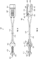
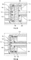
- FIGS. 1-6 illustrate an embodiment of a dual-chamber syringe 110 of a fluid delivery system 100 (shown in FIG. 19 ).
- the dual-chamber syringe 110 includes a cylindrical syringe barrel 112, an end wall 114, and a syringe collar 116.
- the end wall 114 is disposed at a first end 118 of the syringe barrel 112 while the syringe collar 116 is disposed at a second end 120 of the syringe barrel 112, which is opposite the first end 118.
- the syringe collar 116 extends radially outwardly from the syringe barrel 112 proximate the second end 120.
- the syringe barrel 112 includes a cylindrical inner chamber 122 extending between the end wall 114 and the syringe collar 116.
- a grooved channel 124 is recessed in an inner face 126 of the end wall 114.
- the inner face 126 faces the inner chamber 122 and is disposed therein.
- the channel 124 includes a notch end 128, a passage end 130, and a divot 132 disposed between the notch end 128 and the passage end 130.
- the channel 124 includes opposing beveled walls 134, which extend between the notch end 128 and the divot 132 and between the divot 132 and the passage end 130.
- the notch end 128 is in fluid communication with a notch 136, which is disposed in the syringe barrel 112 at an intersection of the syringe barrel 112 and the end wall 114 proximate the first end 118.
- the notch 136 extends axially inwardly from the end wall 114 within the inner chamber 122.
- the passage end 130 is in fluid communication with a passage 138 disposed through the end wall 114.
- the channel 124 extends along a portion of a diameter of the inner face 126.
- the notch 136, the channel 124, and the passage 138 collectively form a flushing fluid flow path of which the features and functionality will be described in more detail below.
- the dual-chamber syringe 110 also includes an internal tube 140.
- the internal tube 140 is disposed through the divot 132 and the inner face 126 of the end wall 114 and extends axially inwardly within the inner chamber 122.
- the internal tube 140 terminates within the inner chamber 122 and is offset axially inwardly with respect to the syringe collar 116.
- the internal tube 140 extends substantially centrally through the divot 132 and the inner face 126 of the end wall 114 and is disposed centrally within the inner chamber 122.
- the dual-chamber syringe 110 also includes a primary nozzle 142 and a secondary nozzle 144. Both the primary nozzle 142 and the secondary nozzle 144 extend axially outwardly from the end wall 114 and are disposed externally with respect to the inner chamber 122. In some aspects, the secondary nozzle 144 is disposed centrally on the end wall 114. The secondary nozzle 144 is coaxially aligned with the internal tube 140 and is in fluid communication with the internal tube 140. The primary nozzle 142 is radially offset on the end wall 114 from the secondary nozzle 144. The primary nozzle 142 is in fluid communication with a primary chamber 145 of the inner chamber 122 via the passage 138.
- a nozzle guide 143 also extends axially outwardly from the end wall 114 and surrounds both the primary nozzle 142 and the secondary nozzle 144 to facilitate connecting the dual-chamber syringe 110 to other medical components.
- the primary nozzle 142 and the secondary nozzle 144 are asymmetrical to prevent reversed or backwards coupling of the dual-chamber syringe 110 to the dual-lumen IV set (800).
- the primary nozzle 142 and the secondary nozzle 144 are male Luer connectors.
- the primary nozzle 142 is a male Luer connector and the secondary nozzle 144 is a needle-free connector.
- the primary nozzle 142 is a needle-free connector and the secondary nozzle 144 is a male Luer connector.
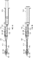
- the dual-chamber syringe 110 includes a primary plunger 146 and a secondary plunger 148.
- the primary plunger 146 is in mechanical association with the secondary plunger 148, such that both are received by the inner chamber 122 and are configured for slidable movement within the inner chamber 122.
- the primary plunger 146 includes a primary stopper 150, a primary head 152, and a rod 154 extending between the primary stopper 150 and the primary head 152.
- the primary stopper 150 is disposed at a first rod end 156 of the rod 154 and the primary head 152 is disposed at a second rod end 1 58 of the rod 154.
- the primary plunger 146 is arranged within the inner chamber 122, such that a primary chamber 159 is disposed between the primary stopper 150 and the inner face 126 of the end wall 114.
- the primary plunger 146 includes a primary receiving aperture 160 disposed centrally through the primary stopper 150.
- the rod 154 extends from the primary stopper 150 and includes a primary inner cavity 162, such that the primary inner cavity 162 is aligned with the primary receiving aperture 160.
- the primary receiving aperture 160 and the primary inner cavity 162 are configured to slidably receive the internal tube 140 of the dual-chamber syringe 110.
- a first primary O-ring 164 is disposed in the primary receiving aperture 160, such that the internal tube 140 is slidably and sealingly received by the first primary O-ring 164 and is slidably received by the primary inner cavity 162.
- a chamber passage 166 is disposed through the rod 154 proximate an intersection of the rod 154 and the primary stopper 150.
- a second primary O-ring 168 is disposed around the primary stopper 150 for sealing engagement with syringe barrel 112.
- the primary plunger 146 includes a lock member 170 disposed on the rod 154 between the primary inner cavity 162 and the primary head 152.
- the lock member 170 includes opposed rod flanges 172.
- Each rod flange of the opposed rod flanges 172 includes a tapered tab 174, which protrudes radially outwardly and tapers axially towards the primary head 152.
- the opposed rod flanges 172 are depressible radially inwardly toward each other.
- the lock member 170 is mechanically associated with components of the secondary plunger 148 to releasably lock with the primary plunger 146, which will be described in more detail below.
- the secondary plunger 148 includes a secondary stopper 176, a secondary head 178, and a body 180 extending between the secondary stopper 176 and the secondary head 178.
- the secondary stopper 1 76 is disposed at a first body end 182 of the body 180 and the secondary head 178 is disposed at a second body end 184 of the body 180.
- the body 180 includes a main section 186 and a neck section 188.
- the main section 186 of the body 180 includes wings including a plus-sign (e.g., +) cross-section.
- the main section 186 transitions to the neck section 188 at a tapered section 190.
- the neck section 188 includes a neck 192 disposed between the tapered section 190 and the secondary head 178.
- the neck 192 includes, sequentially in a direction from the tapered section 190 to the secondary head 178, first opposed plunger slots 194, second opposed plunger slots 196, opposed activator lock slots 198, and opposed activator rest slots 200.
- the secondary plunger 148 includes a secondary receiving aperture 201 disposed centrally through the secondary stopper 176 and a head aperture 202 disposed centrally through the secondary head 178.
- the secondary plunger 148 includes a secondary inner cavity 203 extending from the secondary stopper 176 at the secondary receiving aperture 201 to the secondary head 178 at the head aperture 202.
- the secondary receiving aperture 201 and the secondary inner cavity 203 are configured to slidably receive the rod 154 of the primary plunger 146.
- a secondary chamber 199 of the inner chamber 122 is disposed between the secondary stopper 176 and the primary stopper 150.
- a first secondary O-ring 204 is disposed in the secondary receiving aperture 201, such that the rod 154 is slidably and sealingly received by the first secondary O-ring 204 and is slidably received by the secondary inner cavity 203.
- a second secondary O-ring 205 is disposed around the secondary stopper 176 for sealing engagement with the syringe barrel 112.
- Opposed lock flanges 206 protrude outwardly from the neck 192 and extend axially alongside the neck 192.
- a nub 208 protrudes radially inwardly from each lock flange of the opposed lock flanges 206.
- the nubs 208 are aligned with the second opposed plunger slots 196.
- the opposed lock flanges 206 are configured to urge radially inwardly toward each other, such that nubs 208 are received by the second opposed plunger slots 196.
- the opposed lock flanges 206 are deformable and configured to be urged radially outwardly away from each other when engaged with a pin 209a.
- the pin 209a includes a pull tab 209b formed to a clasp 209c, such that the clasp 209c is removably fastened around the neck 192 and arranged between the opposed lock flanges 206 and the neck 192 to urge the opposed lock flanges 206 radially outwardly.
- the nubs 208 are held radially outwardly away from the second opposed plunger slots 196.
- the secondary plunger 148 includes a seat 210 centrally recessed into the secondary head 178 and aligned coaxially with the secondary inner cavity 203 and the head aperture 202.
- the secondary plunger 148 also includes an activator 212.
- the activator 212 includes an activator body 214 and an activator head 216, which sits on the activator body 214.
- the activator body 214 is substantially cylindrical and includes opposed activator flanges 218 formed in the activator body 214.
- Each activator flange of the opposed activator flanges 218 includes a tapered tab 220, which protrudes radially outwardly and tapers axially inwardly.
- the opposed activator flanges 218 are depressible radially inwardly toward each other.
- the activator body 214 is received by the head aperture 202, such that, in the inactivated state of the activator 212, the tapered tabs 220 of the opposed activator flanges 218 are received by the opposed activator rest slots 200 and, in an activated state of the activator 212, the tapered tabs 220 are received by, and seated at, the opposed activator lock slots 198 while the activator head 216 is received by the seat 210.
- a resilient member 222 is disposed within the neck 192 between the activator head 216 and the primary head 152 of the primary plunger 146. The resilient member 222 is in an uncompressed state when the activator 212 is in the inactivated state and is in a compressed state when the activator 212 is in the activated state.
- the fluid delivery system 100 also includes a dual-lumen intravenous (IV) set 800, which is couplable to the dual-chamber syringe 110.
- IV intravenous
- the dual-lumen IV set 800 includes a connector 810, a valve housing 812, a valve 814, a primary lumen 816, a secondary lumen 818, and an adapter 820.
- the connector 810 includes an exit port 822 and a channel 824 fluidly connected to the exit port 822.
- the connector 810 is configured to couple with a medical device, such as, for example, a catheter (now shown).
- a medical device such as, for example, a catheter (now shown).
- the channel 824 is also fluidly connected to a housing passage 826 disposed in the valve housing 812. In some aspects, the channel 824 tapers from the housing passage 826 toward the exit port 822.
- a housing port 828 is also disposed in the valve housing 812 and is in fluid communication with the housing passage 826.
- each of the primary lumen 816 and the secondary lumen 818 are received by, and in fluid communication with, the housing port 828.
- the other end of the primary lumen 816 is in fluid communication with a primary duct 830 disposed in the adapter 820 while the other end of the secondary lumen 818 is in fluid communication with a secondary duct 832 also disposed in the adapter 820, which is offset from the primary duct 830.
- the valve 814 is disposed in the valve housing 812 and is configured to seal the housing port 828 from the housing passage 826 until a predetermined cracking pressure is achieved against the valve 814 from the housing port 828 at which point fluid is allowed to flow from the housing port 828 past the valve 814 and to the housing passage 826.
- the valve 814 is a one-way valve, such as, but not limited to, a check valve or an anti-siphon valve.
- the predetermined cracking pressure can be selected to crack at any predetermine pressure, such as, for example, 1 psi (pounds per square inch) or a half psi.
- the adapter 820 also includes a primary septum 834 and a secondary septum 836.
- the primary septum 834 is disposed in the primary duct 830.
- the primary septum 834 is configured to seal a primary port 838 of the adapter 820, which is disposed at an end of the primary duct 830, to prevent fluid flow from the primary port 838 to the primary duct 830 when unengaged with a medical device.
- the primary nozzle 142 engages the primary septum 834 allowing fluid from the primary nozzle 142 to flow through the primary port 838 to the primary lumen 816 via the primary duct 830.
- the secondary septum 836 is disposed in the secondary duct 832 and is configured to seal a secondary port 840 of the adapter 820, which is disposed at an end of the secondary duct 832, to prevent fluid flow from the secondary duct 832 to the secondary port 840 when unengaged with a medical device.
- the adapter 820 is coupled to the dual-chamber syringe 110, however, the secondary nozzle 144 engages the secondary septum 836 allowing fluid from the secondary duct 832 to flow through the secondary port 840 to the secondary nozzle 144.
- a secondary valve 842 is disposed in the secondary duct 832 to allow fluid flow from the secondary lumen 818 to the secondary nozzle 144 via the secondary duct 832, but prevents fluid flow in the opposite direction from the secondary nozzle 144 to secondary lumen 818.
- the secondary valve 842 is a one-way valve, such as, but not limited to a duckbill valve or a check valve.
- the primary nozzle 142 and the secondary nozzle 144 are asymmetrical, the primary nozzle 142 is configured to be received only by the primary port 838 and cannot be received by the secondary port 840 while the secondary nozzle 144 is configured to be received only by the secondary port 840 and cannot be received by the primary port 838 to prevent reversed or backwards coupling of the dual-chamber syringe 110 to the dual-lumen IV set 800.
- the adapter 820 also includes a ridge 844 disposed around the exterior and axially offset inwardly from the primary port 838 and the secondary port 840.
- the ridge 844 is configured to removably snap fit or interlock with a seat 846 disposed on the interior of the nozzle guide 143 when the dual-chamber syringe 110 and the dual-lumen IV set 800 are coupled together.
- a first plurality of serrations 848 is disposed on the exterior of the adapter 820 to facilitate gripping when being hand-held.
- the fluid delivery system 100 also includes a dual-chamber syringe adapter 1100.
- the dual-chamber syringe adapter 1100 is couplable to the dual-chamber syringe 110 and a vial adapter 1110 (shown in FIG. 17 ), which is in turn coupled to a vial 1112 (also shown in FIG. 17 ).
- the dual-chamber syringe adapter 1100 is configured to transfer fluid in the vial 1112 to the dual-chamber syringe 110.
- the dual-chamber syringe adapter 1100 includes a male connector 1114, a primary nozzle receiver 1116, a secondary nozzle receiver 1118, and a conduit 1120.
- a second plurality of serrations 1121 is disposed on the exterior of the dual-chamber syringe adapter 1100 to facilitate gripping when being hand-held.
- the conduit 1120 is disposed through the dual-chamber syringe adapter 1100 and fluidly couples the male connector 1114 to the primary nozzle receiver 1116.
- a nozzle seat 1122 is disposed in the secondary nozzle receiver 1118 for sealing engagement with the secondary nozzle 144 and preventing any fluid flow through the secondary nozzle 144.
- the dual-chamber syringe adapter 1100 also includes a cap 1124 hingedly coupled to the male connector 1114 for removably capping or closing the male connector 1114.
- the male connector 1114 is a male Luer connector.
- the male connector 1114 is configured to couple with a female connector of the vial adapter 1110.
- the primary nozzle receiver 1116 is configured to matingly receive the primary nozzle 142 of the dual-chamber syringe 110 and the secondary nozzle receiver 1118 is configured to matingly receive the secondary nozzle 144 of the dual-chamber syringe 110 while an adapter ridge 1126 disposed on the exterior of the dual-chamber syringe adapter 1100 removably snap fits or interlocks with the seat 846.
- the fluid delivery system 100 also includes a flush syringe adapter 1300.
- the flush syringe adapter 1300 is couplable to a flush syringe 1310 (shown in FIG. 15 ) and the adapter 820 of the dual-lumen IV set 800.
- the flush syringe adapter 1300 is configured to transfer fluid from the flush syringe 1310 to prime the dual-lumen IV set 800 with saline.
- the flush syringe adapter 1300 includes a primary adapter nozzle 1312, a secondary adapter nozzle 1314, a syringe guide 1316, a female connector 1318, a primary passage 1320, and a secondary passage 1322.
- a third plurality of serrations 1324 is disposed on the exterior of the flush syringe adapter 1300 to facilitate gripping when being hand-held.
- the syringe guide 1316 surrounds the primary adapter nozzle 1312 and the secondary adapter nozzle 1314 to facilitate coupling the flush syringe adapter 1300 to the dual-lumen IV set 800 so that the primary adapter nozzle 1312 is received by the primary port 838 of the adapter 820 and the secondary adapter nozzle 1314 is received by the secondary port 840.
- the primary adapter nozzle 1312 and the secondary adapter nozzle 1314 are asymmetrical, such that the primary adapter nozzle 1312 is configured to be received only by the primary port 838 and cannot be received by the secondary port 840 while the secondary adapter nozzle 1314 is configured to be received only by the secondary port 840 and cannot be received by the primary port 838 to prevent reversed or backwards coupling of the flush syringe adapter 1300 to the dual-lumen IV set 800.
- the primary adapter nozzle 1312 and the secondary adapter nozzle 1314 are male Luer connectors.
- the primary adapter nozzle 1312 is a male Luer connector and the secondary adapter nozzle 1314 is a needle-free connector.
- the primary adapter nozzle 1312 is a needle-free connector and the secondary adapter nozzle 1314 is a male Luer connector.
- the primary passage 1320 is disposed between, and fluidly couples, the primary adapter nozzle 1312 and an adapter port 1328 disposed at the female connector 1318.
- the female connector 1318 is a female Luer connector.
- the female connector 1318 is configured to couple with a male connector of the flush syringe 1310.
- the male connector of the flush syringe 1310 is a male Luer connector.
- the secondary passage 1322 is disposed between, and fluidly couples, the secondary adapter nozzle 1314 and a vent 1330.
- a hydrophobic element 1332 is disposed in the secondary passage 1322 and is configured to allow air from the secondary adapter nozzle 1314 to escape through the vent 1330, but when the hydrophobic element 1332 contacts liquid fluid (e.g., saline from the flush syringe 1310) it prevents the liquid fluid from flowing out of the vent 1330.
- liquid fluid e.g., saline from the flush syringe 1310
- FIG. 15 illustrates the dual-lumen IV set 800 in use with the flush syringe 1310 in a pre-priming state
- FIG. 16 illustrates the dual-lumen IV set 800 in use with the flush syringe 1310 in a post-priming state.
- the flush syringe adapter 1300 is coupled to the dual-lumen IV set 800, such that the primary adapter nozzle 1312 and the secondary adapter nozzle 1314 are received by the primary port 838 and the secondary port 840, respectively, and the adapter seat 1326 removably snap fits with the ridge 844 of the adapter 820.
- the dual-chamber syringe adapter 1100 which is pre-filled with saline, is coupled to the flush syringe adapter 1300 via the female connector 1318.
- the flush syringe 1310 delivers the saline through the adapter port 1328 and the primary passage 1320 into the primary port 838 and the primary duct 830.
- the saline flows from the primary duct 830 through the primary lumen 816 until it reaches the housing port 828 and the valve 814.
- the pressure against the valve 814 is less than the predetermined cracking pressure so the saline travels through the secondary lumen 818 and the secondary valve 842.
- the flush syringe adapter 1300 along with the flush syringe 1310, is then uncoupled from the dual-lumen IV set 800.
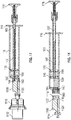
- FIG. 17 illustrates the dual-chamber syringe 110 in a pre-filled state and in use with the vial 1112
- FIG. 18 illustrates the dual-chamber syringe 110, in a post-filled state with the vial 1112 and the dual-chamber syringe adapter 1100 uncoupled from the dual-chamber syringe 110.
- the pin 209a is inserted around the neck 192 urging the opposed lock flanges 206 radially outwardly, such that the nubs 208 are held radially outwardly away from the second opposed plunger slots 196.
- the tapered tabs 174 of the lock member 170 are removably received at the second opposed plunger slots 196 locking the primary plunger 146 to the secondary plunger 148.
- the tapered tabs 220 of the opposed activator flanges 218 are received by and seated at the opposed activator rest slots 200, such that the resilient member 222 is in its uncompressed state between the primary head 152 of the primary plunger 146 and the activator head 216.
- This arrangement locks the primary plunger 146 to the secondary plunger 148 so that the primary stopper 150 is offset from the secondary stopper 176 at a predetermined distance, which can be preselected according to specific desires of a pre-filled volume of the secondary chamber 199.
- the dual-chamber syringe 110 is pre-filled with saline in the secondary chamber 199, as illustrated in FIG. 17 .
- the activator 212 of the dual-chamber syringe 110 is activated by compressing the activator head 216 axially inward, such that the tapered tabs 220 of the opposed activator flanges 218 are depressed radially towards each other, unseated from the opposed activator rest slots 200, and received by the opposed activator lock slots 198 in locking fashion while the activator head 216 is received by the seat 210.
- the resilient member 222 is in its compressed state between the primary head 152 of the primary plunger 146 and the activator head 216 positioned at the seat 210.
- Allowing the resilient member 222 to be in the uncompressed state before use can extend the shelf life of the dual-chamber syringe 110.
- the dual-chamber syringe 110 is coupled to the dual-chamber syringe adapter 1100, such that the nozzle guide 143 facilitates the primary nozzle 142 being matingly inserted into the primary nozzle receiver 1116 and the secondary nozzle 144 being matingly inserted into the secondary nozzle receiver 1118 while the adapter ridge 1126 removably snap fits or interlocks with the seat 846.
- the saline is prevented from accidentally flowing out of the secondary chamber 199 during fluid transfer from the vial 1112 to the dual-chamber syringe 110.
- the male connector 1114 is coupled to the vial adapter 1110, which is coupled to the vial 1112.
- the fluid in the vial 1112 e.g., medicine
- the dual-chamber syringe adapter 1100 can be uncoupled from the dual-chamber syringe 110, as depicted in FIG. 18 .
- FIG. 19 illustrates the dual-chamber syringe 110 of the fluid delivery system 100 in a pre-priming of medication state and in use with the dual-lumen IV set 800.
- the dual-lumen IV set 800 is primed with saline and is fluidly coupled to a catheter 1910.
- the dual-lumen IV set 800 is also fluidly coupled to the dual-chamber syringe 110, which is in mechanical engagement with a syringe pump 1920. While the syringe pump 1920 securely supports the syringe barrel 112, the syringe pump 1920 is also in mechanical engagement with the secondary head 178 to selectively control axially movement of the secondary plunger 148.
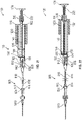
- the dual-chamber syringe 110 and dual-lumen IV set 800 transition to a post-priming of medication state, as illustrated in FIG. 20 .
- the transition involves removing the pin 209a from the neck 192, such that the opposed lock flanges 206 are urged radially towards each other and the nubs 208 engage the tapered tabs 174 of the lock member 170 releasing the tapered tabs 174 from the second opposed plunger slots 196.
- the release or unseating of the tapered tabs 174 from the second opposed plunger slots 196 allows the resilient member 222, in the compressed state, to urge against the primary head 152, which in turn urges the primary plunger 146 axially toward the end wall 114.
- the medication in the primary chamber 159 is forced through the passage 138 and out the primary nozzle 142 into the primary duct 830 to the primary lumen 816.
- the medication is displacing the saline that was primed in the dual-lumen IV set 800 to travel out the secondary port 840 and through the secondary nozzle 144 to fill the secondary chamber 199 via the internal tube 140, the primary inner cavity 162, and the chamber passage 166.
- the primary plunger 146 continues to prime the dual-lumen IV set 800 with the medication until the tapered tabs 174 are received by, and seated against, the first opposed plunger slots 194, which prevents the resilient member 222 from urging the primary plunger 146 any further.
- the dual-chamber syringe 110 and dual-lumen IV set 800 transition to a pre-flushing state, as illustrated in FIG. 21 .
- the transition involves the syringe pump 1920 moving the secondary head 178 of the secondary plunger 148 axially toward the end wall 114 to deliver the remaining medication in the primary chamber 159 through the passage 138 and the primary nozzle 142 to the primary duct 830 and the primary lumen 816.
- the secondary valve 842 prevents saline flow from the secondary chamber 199 to the secondary lumen 818, pressure is increased against the valve 814 as the secondary plunger 148 is moved axially and is greater than the predetermined cracking pressure, such that the axially movement of the secondary plunger 148 forces the medication past the valve 814 and into the housing passage 826 to the catheter 1910 via the channel 824 and the exit port 822.
- the tapered tabs 174 are unseated from the first opposed plunger slots 194 and are moved towards the second opposed plunger slots 196.
- FIG. 23 illustrates the pre-flushing state with the primary stopper 150 abutting the inner face 126 of the end wall 114 and medication residing in the channel 124 and the notch 136.
- the second primary O-ring 168 seals the notch 136 and prevents the medication from flowing into the secondary chamber 199.
- the pressure against the second primary O-ring 168 increases, such that the saline in the secondary chamber 199 is forced past the second primary O-ring 168 and through the notch 136 into the channel 124 and forces the medication to the primary nozzle 142 via the passage 138.
- the syringe pump 1920 continues to axially move the secondary plunger 148, such that the saline is forced from the secondary chamber 199 to flush the medication from the channel 124. In this manner, the saline forces the medication through the primary lumen 816 so that all of the medication is delivered to the patient and the dual-lumen IV set 800 is primed with saline.
- the dual-chamber syringe is pre-loaded with saline in the secondary chamber 199.
- the secondary chamber 199 is configured to receive the priming solution from the dual-lumen IV set 800, but is not utilized for reserved flushing.
- the secondary chamber 199 is configured to stop the secondary plunger 148 when receiving priming solution from the dual-lumen IV set 800 and is configured to indicate the dual-chamber syringe 110 is ready to infuse medication.
- the fluid delivery system 100 includes a valve lock to prevent fluid from being delivered to a patient during priming.
- the priming volume is selectable in 0.1 mL increments.
- the secondary plunger 148 includes a plunger handle base that rotates to allow the plunger rod to rotate and disengage while maintaining friction with a syringe pump paddle. In some aspects, the secondary plunger 148 is released automatically, instead of with a pin 209a, at a certain plunger depth so that infusion is not interrupted and does not require human interaction. In some aspects, the fluid delivery system 100 includes vents to vent residual air bubbles via air-permeable filters. In some aspects, the fluid delivery system 100 is configured to pre-set and limit the priming volume via a pin which limits plunger travel.
- the phrase "at least one of” preceding a series of items, with the term “and” or “or” to separate any of the items, modifies the list as a whole, rather than each member of the list (i.e., each item).
- the phrase "at least one of” does not require selection of at least one of each item listed; rather, the phrase allows a meaning that includes at least one of any one of the items, and/or at least one of any combination of the items, and/or at least one of each of the items.
- phrases “at least one of A, B, and C” or “at least one of A, B, or C” each refer to only A, only B, or only C; any combination of A, B, and C; and/or at least one of each of A, B, and C.
Landscapes
- Health & Medical Sciences (AREA)
- Vascular Medicine (AREA)
- Engineering & Computer Science (AREA)
- Anesthesiology (AREA)
- Biomedical Technology (AREA)
- Heart & Thoracic Surgery (AREA)
- Hematology (AREA)
- Life Sciences & Earth Sciences (AREA)
- Animal Behavior & Ethology (AREA)
- General Health & Medical Sciences (AREA)
- Public Health (AREA)
- Veterinary Medicine (AREA)
- Infusion, Injection, And Reservoir Apparatuses (AREA)
Claims (10)
- Seringue à double chambre (110), comprenant :une paroi d'extrémité (114) ;un plongeur primaire (146) comprenant une butée primaire (150) et une tige (154) s'étendant depuis la butée primaire (150), la butée primaire (150) formant une chambre primaire (159) avec la paroi d'extrémité (114) ;et caractérisée en ce qu'elle comprend en outre un plongeur secondaire (148) en association mécanique avec le plongeur primaire (146), le plongeur secondaire (148) définissant une cavité intérieure secondaire (203) et comprenant une butée secondaire (176), la butée secondaire (176) formant une chambre secondaire (199) avec la butée primaire (150), sachant que la cavité intérieure secondaire (203) est configurée pour recevoir la tige (154) du plongeur primaire (146) ;une buse primaire (142) s'étendant depuis la paroi d'extrémité (114), la buse primaire (142) étant en communication fluidique avec la chambre primaire (159) ; etune buse secondaire (144) s'étendant depuis la paroi d'extrémité (114), la buse secondaire (144) étant en communication fluidique avec la chambre secondaire (199).
- La seringue à double chambre (110) de la revendication 1, sachant que la buse secondaire (144) s'étend centralement depuis la paroi d'extrémité (114).
- La seringue à double chambre (110) de la revendication 2, sachant que la buse primaire (142) est décalée radialement par rapport à la buse secondaire (144).
- La seringue à double chambre (110) de la revendication 1, sachant que la buse primaire (142) et la buse secondaire (144) sont asymétriques.
- La seringue à double chambre (110) de la revendication 1, comprenant en outre un guide de buses (143) s'étendant depuis la paroi d'extrémité (114) et entourant la buse primaire (142) et la buse secondaire (144).
- La seringue à double chambre (110) de la revendication 1, sachant que le plongeur primaire (146) est verrouillable par rapport au plongeur secondaire (148).
- La seringue à double chambre (110) de la revendication 1, sachant que la paroi d'extrémité (114) comprend un canal (124) .
- La seringue à double chambre (110) de la revendication 7, sachant que la chambre secondaire (199) est en communication fluidique avec la buse primaire (142) via le canal (124) lorsque la seringue à double chambre (110) passe d'un état de pré-rinçage à un état de post-rinçage.
- La seringue à double chambre (110) de la revendication 1, sachant que la buse secondaire (144) est en communication fluidique avec la chambre secondaire (199) via un tube interne s'étendant depuis la paroi d'extrémité (114).
- La seringue à double chambre (110) de la revendication 9, sachant que le tube interne est reçu par une cavité intérieure primaire (162) du plongeur primaire (146).
Priority Applications (1)
| Application Number | Priority Date | Filing Date | Title |
|---|---|---|---|
| EP22202447.3A EP4144400A1 (fr) | 2018-10-11 | 2019-10-10 | Seringue à double chambre avec ensemble intraveineux à double lumière |
Applications Claiming Priority (2)
| Application Number | Priority Date | Filing Date | Title |
|---|---|---|---|
| US201862744500P | 2018-10-11 | 2018-10-11 | |
| PCT/US2019/055701 WO2020077134A1 (fr) | 2018-10-11 | 2019-10-10 | Seringue à double chambre avec ensemble de perfusion intraveineuse à deux lumières |
Related Child Applications (2)
| Application Number | Title | Priority Date | Filing Date |
|---|---|---|---|
| EP22202447.3A Division-Into EP4144400A1 (fr) | 2018-10-11 | 2019-10-10 | Seringue à double chambre avec ensemble intraveineux à double lumière |
| EP22202447.3A Division EP4144400A1 (fr) | 2018-10-11 | 2019-10-10 | Seringue à double chambre avec ensemble intraveineux à double lumière |
Publications (2)
| Publication Number | Publication Date |
|---|---|
| EP3863700A1 EP3863700A1 (fr) | 2021-08-18 |
| EP3863700B1 true EP3863700B1 (fr) | 2022-11-30 |
Family
ID=68387416
Family Applications (2)
| Application Number | Title | Priority Date | Filing Date |
|---|---|---|---|
| EP19795402.7A Active EP3863700B1 (fr) | 2018-10-11 | 2019-10-10 | Seringue à double chambre avec ensemble de perfusion intraveineuse à deux lumières |
| EP22202447.3A Pending EP4144400A1 (fr) | 2018-10-11 | 2019-10-10 | Seringue à double chambre avec ensemble intraveineux à double lumière |
Family Applications After (1)
| Application Number | Title | Priority Date | Filing Date |
|---|---|---|---|
| EP22202447.3A Pending EP4144400A1 (fr) | 2018-10-11 | 2019-10-10 | Seringue à double chambre avec ensemble intraveineux à double lumière |
Country Status (7)
| Country | Link |
|---|---|
| US (2) | US11395879B2 (fr) |
| EP (2) | EP3863700B1 (fr) |
| JP (2) | JP7389798B2 (fr) |
| CN (2) | CN116212165A (fr) |
| AU (1) | AU2019359395A1 (fr) |
| CA (1) | CA3115948A1 (fr) |
| WO (1) | WO2020077134A1 (fr) |
Family Cites Families (23)
| Publication number | Priority date | Publication date | Assignee | Title |
|---|---|---|---|---|
| US2677374A (en) * | 1952-11-07 | 1954-05-04 | Lilly Co Eli | Syringe closure |
| US4689042A (en) | 1985-05-20 | 1987-08-25 | Survival Technology, Inc. | Automatic medicament ingredient mixing and injecting apparatus |
| US4946448A (en) * | 1989-10-23 | 1990-08-07 | Kendall Mcgaw Laboratories, Inc. | Check valve for use with intravenous pump |
| US5396925A (en) * | 1993-12-16 | 1995-03-14 | Abbott Laboratories | Anti-free flow valve, enabling fluid flow as a function of pressure and selectively opened to enable free flow |
| US5865804A (en) * | 1997-07-16 | 1999-02-02 | Bachynsky; Nicholas | Rotary cam syringe |
| IL123227A0 (en) * | 1998-02-08 | 1998-09-24 | 3By Ltd | Check valve |
| US6428528B2 (en) * | 1998-08-11 | 2002-08-06 | Antares Pharma, Inc. | Needle assisted jet injector |
| JP3976658B2 (ja) * | 2002-10-08 | 2007-09-19 | 久光製薬株式会社 | キット製剤用注射器、注射器型キット製剤用中間摺動弁、及び、注射器型キット製剤、並びにキット製剤用注射筒の製造方法 |
| US7347853B2 (en) * | 2004-05-12 | 2008-03-25 | C. R. Bard, Inc. | Catheter with removable extension |
| NZ584679A (en) * | 2007-11-22 | 2012-09-28 | Biovitrum Ab Publ | A method and device for the serial ejection of two fluids comprising a spacer to retain a volume of a second fluid for rinsing |
| DE102008004977A1 (de) * | 2008-01-17 | 2009-07-23 | Miltenyi Biotec Gmbh | Vorrichtung zur Entnahme von biologischem Material |
| US8152778B2 (en) | 2008-09-30 | 2012-04-10 | Tyco Healthcare Group Lp | Device for interfacing with standard luer lock syringes |
| CN102458521B (zh) * | 2009-06-04 | 2014-06-04 | 诺沃—诺迪斯克保健股份有限公司 | 具有活塞联接布置的混合设备 |
| CH703402B1 (de) * | 2010-07-05 | 2014-12-15 | Daniel Schmidlin | Mehr-Lumen-Verlängerung. |
| US9950114B2 (en) * | 2011-05-13 | 2018-04-24 | Thorne Consulting For International Property, Llc | Dual-chamber syringe and associated connecting systems |
| EP2806918B1 (fr) * | 2012-01-23 | 2019-10-23 | Bee Sight Limited | Dispositifs pour seringues auto-rinçables |
| US20130274719A1 (en) | 2012-04-11 | 2013-10-17 | Richard E. Berkey | Cutaneous abscess drainage device and methods |
| US8808233B2 (en) * | 2012-04-12 | 2014-08-19 | Laurie Ausley Nelson | Multiple fluid combining syringe |
| CN104717993B (zh) * | 2012-10-15 | 2017-09-26 | 爱康医学农业合作协会有限公司 | 医疗流体供应装置 |
| US20140121647A1 (en) * | 2012-10-30 | 2014-05-01 | Nordson Corporation | System for dispensing multiple fluids and a method for using the same |
| US9114215B2 (en) * | 2013-03-13 | 2015-08-25 | Bayer Medical Care Inc. | Multiple compartment syringe |
| WO2017114921A1 (fr) * | 2015-12-30 | 2017-07-06 | Novo Nordisk A/S | Mécanisme d'administration séquentielle de dose |
| EP3243549A1 (fr) * | 2016-05-12 | 2017-11-15 | Renishaw plc | Dispositif d'accès percutané |
-
2019
- 2019-10-10 CA CA3115948A patent/CA3115948A1/fr active Pending
- 2019-10-10 CN CN202310269154.XA patent/CN116212165A/zh active Pending
- 2019-10-10 CN CN201980081463.6A patent/CN113195017B/zh active Active
- 2019-10-10 WO PCT/US2019/055701 patent/WO2020077134A1/fr active Search and Examination
- 2019-10-10 JP JP2021519795A patent/JP7389798B2/ja active Active
- 2019-10-10 EP EP19795402.7A patent/EP3863700B1/fr active Active
- 2019-10-10 AU AU2019359395A patent/AU2019359395A1/en active Pending
- 2019-10-10 US US16/598,945 patent/US11395879B2/en active Active
- 2019-10-10 EP EP22202447.3A patent/EP4144400A1/fr active Pending
-
2022
- 2022-06-21 US US17/845,392 patent/US20220323677A1/en active Pending
-
2023
- 2023-11-17 JP JP2023195625A patent/JP2024009111A/ja active Pending
Also Published As
| Publication number | Publication date |
|---|---|
| CA3115948A1 (fr) | 2020-04-16 |
| EP4144400A1 (fr) | 2023-03-08 |
| JP7389798B2 (ja) | 2023-11-30 |
| US20220323677A1 (en) | 2022-10-13 |
| CN113195017B (zh) | 2023-03-28 |
| EP3863700A1 (fr) | 2021-08-18 |
| US20200114079A1 (en) | 2020-04-16 |
| JP2024009111A (ja) | 2024-01-19 |
| CN113195017A (zh) | 2021-07-30 |
| US11395879B2 (en) | 2022-07-26 |
| JP2022504672A (ja) | 2022-01-13 |
| AU2019359395A1 (en) | 2021-05-06 |
| WO2020077134A1 (fr) | 2020-04-16 |
| CN116212165A (zh) | 2023-06-06 |
Similar Documents
| Publication | Publication Date | Title |
|---|---|---|
| JP7535639B2 (ja) | 単一または複数の容器のための貯留デバイス | |
| EP2598189B1 (fr) | Système d'administration sans danger de médicament à aiguille émoussée | |
| US9381339B2 (en) | Safety drug delivery connectors | |
| AU696759B2 (en) | Pre-filled syringe drug delivery system | |
| EP3863700B1 (fr) | Seringue à double chambre avec ensemble de perfusion intraveineuse à deux lumières | |
| US20230390495A1 (en) | Nested Molded Piston Parts For Multi-Chamber Syringes |
Legal Events
| Date | Code | Title | Description |
|---|---|---|---|
| STAA | Information on the status of an ep patent application or granted ep patent |
Free format text: STATUS: UNKNOWN |
|
| STAA | Information on the status of an ep patent application or granted ep patent |
Free format text: STATUS: THE INTERNATIONAL PUBLICATION HAS BEEN MADE |
|
| STAA | Information on the status of an ep patent application or granted ep patent |
Free format text: STATUS: THE INTERNATIONAL PUBLICATION HAS BEEN MADE |
|
| PUAI | Public reference made under article 153(3) epc to a published international application that has entered the european phase |
Free format text: ORIGINAL CODE: 0009012 |
|
| STAA | Information on the status of an ep patent application or granted ep patent |
Free format text: STATUS: REQUEST FOR EXAMINATION WAS MADE |
|
| 17P | Request for examination filed |
Effective date: 20210505 |
|
| AK | Designated contracting states |
Kind code of ref document: A1 Designated state(s): AL AT BE BG CH CY CZ DE DK EE ES FI FR GB GR HR HU IE IS IT LI LT LU LV MC MK MT NL NO PL PT RO RS SE SI SK SM TR |
|
| DAV | Request for validation of the european patent (deleted) | ||
| DAX | Request for extension of the european patent (deleted) | ||
| GRAP | Despatch of communication of intention to grant a patent |
Free format text: ORIGINAL CODE: EPIDOSNIGR1 |
|
| STAA | Information on the status of an ep patent application or granted ep patent |
Free format text: STATUS: GRANT OF PATENT IS INTENDED |
|
| INTG | Intention to grant announced |
Effective date: 20220622 |
|
| GRAS | Grant fee paid |
Free format text: ORIGINAL CODE: EPIDOSNIGR3 |
|
| GRAA | (expected) grant |
Free format text: ORIGINAL CODE: 0009210 |
|
| STAA | Information on the status of an ep patent application or granted ep patent |
Free format text: STATUS: THE PATENT HAS BEEN GRANTED |
|
| AK | Designated contracting states |
Kind code of ref document: B1 Designated state(s): AL AT BE BG CH CY CZ DE DK EE ES FI FR GB GR HR HU IE IS IT LI LT LU LV MC MK MT NL NO PL PT RO RS SE SI SK SM TR |
|
| REG | Reference to a national code |
Ref country code: CH Ref legal event code: EP Ref country code: GB Ref legal event code: FG4D |
|
| REG | Reference to a national code |
Ref country code: AT Ref legal event code: REF Ref document number: 1534183 Country of ref document: AT Kind code of ref document: T Effective date: 20221215 Ref country code: DE Ref legal event code: R096 Ref document number: 602019022627 Country of ref document: DE |
|
| REG | Reference to a national code |
Ref country code: IE Ref legal event code: FG4D |
|
| REG | Reference to a national code |
Ref country code: LT Ref legal event code: MG9D |
|
| REG | Reference to a national code |
Ref country code: NL Ref legal event code: MP Effective date: 20221130 |
|
| PG25 | Lapsed in a contracting state [announced via postgrant information from national office to epo] |
Ref country code: SE Free format text: LAPSE BECAUSE OF FAILURE TO SUBMIT A TRANSLATION OF THE DESCRIPTION OR TO PAY THE FEE WITHIN THE PRESCRIBED TIME-LIMIT Effective date: 20221130 Ref country code: PT Free format text: LAPSE BECAUSE OF FAILURE TO SUBMIT A TRANSLATION OF THE DESCRIPTION OR TO PAY THE FEE WITHIN THE PRESCRIBED TIME-LIMIT Effective date: 20230331 Ref country code: NO Free format text: LAPSE BECAUSE OF FAILURE TO SUBMIT A TRANSLATION OF THE DESCRIPTION OR TO PAY THE FEE WITHIN THE PRESCRIBED TIME-LIMIT Effective date: 20230228 Ref country code: LT Free format text: LAPSE BECAUSE OF FAILURE TO SUBMIT A TRANSLATION OF THE DESCRIPTION OR TO PAY THE FEE WITHIN THE PRESCRIBED TIME-LIMIT Effective date: 20221130 Ref country code: FI Free format text: LAPSE BECAUSE OF FAILURE TO SUBMIT A TRANSLATION OF THE DESCRIPTION OR TO PAY THE FEE WITHIN THE PRESCRIBED TIME-LIMIT Effective date: 20221130 Ref country code: ES Free format text: LAPSE BECAUSE OF FAILURE TO SUBMIT A TRANSLATION OF THE DESCRIPTION OR TO PAY THE FEE WITHIN THE PRESCRIBED TIME-LIMIT Effective date: 20221130 |
|
| REG | Reference to a national code |
Ref country code: AT Ref legal event code: MK05 Ref document number: 1534183 Country of ref document: AT Kind code of ref document: T Effective date: 20221130 |
|
| PG25 | Lapsed in a contracting state [announced via postgrant information from national office to epo] |
Ref country code: RS Free format text: LAPSE BECAUSE OF FAILURE TO SUBMIT A TRANSLATION OF THE DESCRIPTION OR TO PAY THE FEE WITHIN THE PRESCRIBED TIME-LIMIT Effective date: 20221130 Ref country code: PL Free format text: LAPSE BECAUSE OF FAILURE TO SUBMIT A TRANSLATION OF THE DESCRIPTION OR TO PAY THE FEE WITHIN THE PRESCRIBED TIME-LIMIT Effective date: 20221130 Ref country code: LV Free format text: LAPSE BECAUSE OF FAILURE TO SUBMIT A TRANSLATION OF THE DESCRIPTION OR TO PAY THE FEE WITHIN THE PRESCRIBED TIME-LIMIT Effective date: 20221130 Ref country code: IS Free format text: LAPSE BECAUSE OF FAILURE TO SUBMIT A TRANSLATION OF THE DESCRIPTION OR TO PAY THE FEE WITHIN THE PRESCRIBED TIME-LIMIT Effective date: 20230330 Ref country code: HR Free format text: LAPSE BECAUSE OF FAILURE TO SUBMIT A TRANSLATION OF THE DESCRIPTION OR TO PAY THE FEE WITHIN THE PRESCRIBED TIME-LIMIT Effective date: 20221130 Ref country code: GR Free format text: LAPSE BECAUSE OF FAILURE TO SUBMIT A TRANSLATION OF THE DESCRIPTION OR TO PAY THE FEE WITHIN THE PRESCRIBED TIME-LIMIT Effective date: 20230301 |
|
| PG25 | Lapsed in a contracting state [announced via postgrant information from national office to epo] |
Ref country code: NL Free format text: LAPSE BECAUSE OF FAILURE TO SUBMIT A TRANSLATION OF THE DESCRIPTION OR TO PAY THE FEE WITHIN THE PRESCRIBED TIME-LIMIT Effective date: 20221130 |
|
| PG25 | Lapsed in a contracting state [announced via postgrant information from national office to epo] |
Ref country code: SM Free format text: LAPSE BECAUSE OF FAILURE TO SUBMIT A TRANSLATION OF THE DESCRIPTION OR TO PAY THE FEE WITHIN THE PRESCRIBED TIME-LIMIT Effective date: 20221130 Ref country code: RO Free format text: LAPSE BECAUSE OF FAILURE TO SUBMIT A TRANSLATION OF THE DESCRIPTION OR TO PAY THE FEE WITHIN THE PRESCRIBED TIME-LIMIT Effective date: 20221130 Ref country code: EE Free format text: LAPSE BECAUSE OF FAILURE TO SUBMIT A TRANSLATION OF THE DESCRIPTION OR TO PAY THE FEE WITHIN THE PRESCRIBED TIME-LIMIT Effective date: 20221130 Ref country code: DK Free format text: LAPSE BECAUSE OF FAILURE TO SUBMIT A TRANSLATION OF THE DESCRIPTION OR TO PAY THE FEE WITHIN THE PRESCRIBED TIME-LIMIT Effective date: 20221130 Ref country code: CZ Free format text: LAPSE BECAUSE OF FAILURE TO SUBMIT A TRANSLATION OF THE DESCRIPTION OR TO PAY THE FEE WITHIN THE PRESCRIBED TIME-LIMIT Effective date: 20221130 Ref country code: AT Free format text: LAPSE BECAUSE OF FAILURE TO SUBMIT A TRANSLATION OF THE DESCRIPTION OR TO PAY THE FEE WITHIN THE PRESCRIBED TIME-LIMIT Effective date: 20221130 |
|
| PG25 | Lapsed in a contracting state [announced via postgrant information from national office to epo] |
Ref country code: SK Free format text: LAPSE BECAUSE OF FAILURE TO SUBMIT A TRANSLATION OF THE DESCRIPTION OR TO PAY THE FEE WITHIN THE PRESCRIBED TIME-LIMIT Effective date: 20221130 Ref country code: AL Free format text: LAPSE BECAUSE OF FAILURE TO SUBMIT A TRANSLATION OF THE DESCRIPTION OR TO PAY THE FEE WITHIN THE PRESCRIBED TIME-LIMIT Effective date: 20221130 |
|
| REG | Reference to a national code |
Ref country code: DE Ref legal event code: R097 Ref document number: 602019022627 Country of ref document: DE |
|
| PLBE | No opposition filed within time limit |
Free format text: ORIGINAL CODE: 0009261 |
|
| STAA | Information on the status of an ep patent application or granted ep patent |
Free format text: STATUS: NO OPPOSITION FILED WITHIN TIME LIMIT |
|
| PGFP | Annual fee paid to national office [announced via postgrant information from national office to epo] |
Ref country code: GB Payment date: 20230920 Year of fee payment: 5 |
|
| 26N | No opposition filed |
Effective date: 20230831 |
|
| PG25 | Lapsed in a contracting state [announced via postgrant information from national office to epo] |
Ref country code: SI Free format text: LAPSE BECAUSE OF FAILURE TO SUBMIT A TRANSLATION OF THE DESCRIPTION OR TO PAY THE FEE WITHIN THE PRESCRIBED TIME-LIMIT Effective date: 20221130 |
|
| PGFP | Annual fee paid to national office [announced via postgrant information from national office to epo] |
Ref country code: FR Payment date: 20230920 Year of fee payment: 5 Ref country code: BE Payment date: 20230920 Year of fee payment: 5 |
|
| PGFP | Annual fee paid to national office [announced via postgrant information from national office to epo] |
Ref country code: DE Payment date: 20230920 Year of fee payment: 5 |
|
| PG25 | Lapsed in a contracting state [announced via postgrant information from national office to epo] |
Ref country code: IT Free format text: LAPSE BECAUSE OF FAILURE TO SUBMIT A TRANSLATION OF THE DESCRIPTION OR TO PAY THE FEE WITHIN THE PRESCRIBED TIME-LIMIT Effective date: 20221130 Ref country code: MC Free format text: LAPSE BECAUSE OF FAILURE TO SUBMIT A TRANSLATION OF THE DESCRIPTION OR TO PAY THE FEE WITHIN THE PRESCRIBED TIME-LIMIT Effective date: 20221130 |
|
| REG | Reference to a national code |
Ref country code: CH Ref legal event code: PL |
|
| PG25 | Lapsed in a contracting state [announced via postgrant information from national office to epo] |
Ref country code: LU Free format text: LAPSE BECAUSE OF NON-PAYMENT OF DUE FEES Effective date: 20231010 |
|
| PG25 | Lapsed in a contracting state [announced via postgrant information from national office to epo] |
Ref country code: LU Free format text: LAPSE BECAUSE OF NON-PAYMENT OF DUE FEES Effective date: 20231010 |
|
| PG25 | Lapsed in a contracting state [announced via postgrant information from national office to epo] |
Ref country code: CH Free format text: LAPSE BECAUSE OF NON-PAYMENT OF DUE FEES Effective date: 20231031 |
|
| PG25 | Lapsed in a contracting state [announced via postgrant information from national office to epo] |
Ref country code: CH Free format text: LAPSE BECAUSE OF NON-PAYMENT OF DUE FEES Effective date: 20231031 |