EP3863575B1 - Ostomy appliance having conductive ink circuit for leakage detection - Google Patents
Ostomy appliance having conductive ink circuit for leakage detection Download PDFInfo
- Publication number
- EP3863575B1 EP3863575B1 EP19791093.8A EP19791093A EP3863575B1 EP 3863575 B1 EP3863575 B1 EP 3863575B1 EP 19791093 A EP19791093 A EP 19791093A EP 3863575 B1 EP3863575 B1 EP 3863575B1
- Authority
- EP
- European Patent Office
- Prior art keywords
- ostomy appliance
- ostomy
- rfid
- leakage
- circuit
- Prior art date
- Legal status (The legal status is an assumption and is not a legal conclusion. Google has not performed a legal analysis and makes no representation as to the accuracy of the status listed.)
- Active
Links
- 238000001514 detection method Methods 0.000 title claims description 7
- 239000012530 fluid Substances 0.000 claims description 40
- 239000000416 hydrocolloid Substances 0.000 claims description 24
- 230000008859 change Effects 0.000 claims description 10
- 230000004044 response Effects 0.000 claims description 9
- 239000000976 ink Substances 0.000 description 24
- 238000004891 communication Methods 0.000 description 17
- 230000008591 skin barrier function Effects 0.000 description 9
- 230000004888 barrier function Effects 0.000 description 8
- 239000000463 material Substances 0.000 description 8
- 239000000758 substrate Substances 0.000 description 8
- 230000008878 coupling Effects 0.000 description 7
- 238000010168 coupling process Methods 0.000 description 7
- 238000005859 coupling reaction Methods 0.000 description 7
- 239000000853 adhesive Substances 0.000 description 6
- 230000001070 adhesive effect Effects 0.000 description 6
- 230000006870 function Effects 0.000 description 6
- 210000002700 urine Anatomy 0.000 description 6
- 239000003990 capacitor Substances 0.000 description 5
- 238000000034 method Methods 0.000 description 5
- 238000012806 monitoring device Methods 0.000 description 4
- 230000005540 biological transmission Effects 0.000 description 3
- OKTJSMMVPCPJKN-UHFFFAOYSA-N Carbon Chemical compound [C] OKTJSMMVPCPJKN-UHFFFAOYSA-N 0.000 description 2
- 229910052799 carbon Inorganic materials 0.000 description 2
- 230000001413 cellular effect Effects 0.000 description 2
- 230000036541 health Effects 0.000 description 2
- 238000010295 mobile communication Methods 0.000 description 2
- 238000012544 monitoring process Methods 0.000 description 2
- 230000008569 process Effects 0.000 description 2
- 230000036559 skin health Effects 0.000 description 2
- 230000000007 visual effect Effects 0.000 description 2
- 230000002745 absorbent Effects 0.000 description 1
- 239000002250 absorbent Substances 0.000 description 1
- 238000007792 addition Methods 0.000 description 1
- 230000006399 behavior Effects 0.000 description 1
- 210000001124 body fluid Anatomy 0.000 description 1
- 230000015556 catabolic process Effects 0.000 description 1
- 239000003086 colorant Substances 0.000 description 1
- 238000006731 degradation reaction Methods 0.000 description 1
- 230000037213 diet Effects 0.000 description 1
- 235000005911 diet Nutrition 0.000 description 1
- 230000000694 effects Effects 0.000 description 1
- 238000005516 engineering process Methods 0.000 description 1
- 239000006261 foam material Substances 0.000 description 1
- 230000001939 inductive effect Effects 0.000 description 1
- 238000009434 installation Methods 0.000 description 1
- 230000002452 interceptive effect Effects 0.000 description 1
- 238000004519 manufacturing process Methods 0.000 description 1
- 238000005259 measurement Methods 0.000 description 1
- 230000037081 physical activity Effects 0.000 description 1
- 239000011295 pitch Substances 0.000 description 1
- 238000007639 printing Methods 0.000 description 1
- 238000011160 research Methods 0.000 description 1
- 238000007789 sealing Methods 0.000 description 1
- 239000007858 starting material Substances 0.000 description 1
- 238000002560 therapeutic procedure Methods 0.000 description 1
- 238000012800 visualization Methods 0.000 description 1
- 230000003313 weakening effect Effects 0.000 description 1
Images


Classifications
-
- A—HUMAN NECESSITIES
- A61—MEDICAL OR VETERINARY SCIENCE; HYGIENE
- A61F—FILTERS IMPLANTABLE INTO BLOOD VESSELS; PROSTHESES; DEVICES PROVIDING PATENCY TO, OR PREVENTING COLLAPSING OF, TUBULAR STRUCTURES OF THE BODY, e.g. STENTS; ORTHOPAEDIC, NURSING OR CONTRACEPTIVE DEVICES; FOMENTATION; TREATMENT OR PROTECTION OF EYES OR EARS; BANDAGES, DRESSINGS OR ABSORBENT PADS; FIRST-AID KITS
- A61F5/00—Orthopaedic methods or devices for non-surgical treatment of bones or joints; Nursing devices; Anti-rape devices
- A61F5/44—Devices worn by the patient for reception of urine, faeces, catamenial or other discharge; Portable urination aids; Colostomy devices
- A61F5/4404—Details or parts
-
- A—HUMAN NECESSITIES
- A61—MEDICAL OR VETERINARY SCIENCE; HYGIENE
- A61F—FILTERS IMPLANTABLE INTO BLOOD VESSELS; PROSTHESES; DEVICES PROVIDING PATENCY TO, OR PREVENTING COLLAPSING OF, TUBULAR STRUCTURES OF THE BODY, e.g. STENTS; ORTHOPAEDIC, NURSING OR CONTRACEPTIVE DEVICES; FOMENTATION; TREATMENT OR PROTECTION OF EYES OR EARS; BANDAGES, DRESSINGS OR ABSORBENT PADS; FIRST-AID KITS
- A61F5/00—Orthopaedic methods or devices for non-surgical treatment of bones or joints; Nursing devices; Anti-rape devices
- A61F5/44—Devices worn by the patient for reception of urine, faeces, catamenial or other discharge; Portable urination aids; Colostomy devices
- A61F5/445—Colostomy, ileostomy or urethrostomy devices
-
- A—HUMAN NECESSITIES
- A61—MEDICAL OR VETERINARY SCIENCE; HYGIENE
- A61F—FILTERS IMPLANTABLE INTO BLOOD VESSELS; PROSTHESES; DEVICES PROVIDING PATENCY TO, OR PREVENTING COLLAPSING OF, TUBULAR STRUCTURES OF THE BODY, e.g. STENTS; ORTHOPAEDIC, NURSING OR CONTRACEPTIVE DEVICES; FOMENTATION; TREATMENT OR PROTECTION OF EYES OR EARS; BANDAGES, DRESSINGS OR ABSORBENT PADS; FIRST-AID KITS
- A61F5/00—Orthopaedic methods or devices for non-surgical treatment of bones or joints; Nursing devices; Anti-rape devices
- A61F5/44—Devices worn by the patient for reception of urine, faeces, catamenial or other discharge; Portable urination aids; Colostomy devices
- A61F5/443—Devices worn by the patient for reception of urine, faeces, catamenial or other discharge; Portable urination aids; Colostomy devices having adhesive seals for securing to the body, e.g. of hydrocolloid type, e.g. gels, starches, karaya gums
-
- A—HUMAN NECESSITIES
- A61—MEDICAL OR VETERINARY SCIENCE; HYGIENE
- A61F—FILTERS IMPLANTABLE INTO BLOOD VESSELS; PROSTHESES; DEVICES PROVIDING PATENCY TO, OR PREVENTING COLLAPSING OF, TUBULAR STRUCTURES OF THE BODY, e.g. STENTS; ORTHOPAEDIC, NURSING OR CONTRACEPTIVE DEVICES; FOMENTATION; TREATMENT OR PROTECTION OF EYES OR EARS; BANDAGES, DRESSINGS OR ABSORBENT PADS; FIRST-AID KITS
- A61F5/00—Orthopaedic methods or devices for non-surgical treatment of bones or joints; Nursing devices; Anti-rape devices
- A61F5/44—Devices worn by the patient for reception of urine, faeces, catamenial or other discharge; Portable urination aids; Colostomy devices
- A61F5/445—Colostomy, ileostomy or urethrostomy devices
- A61F5/448—Means for attaching bag to seal ring
-
- G—PHYSICS
- G01—MEASURING; TESTING
- G01M—TESTING STATIC OR DYNAMIC BALANCE OF MACHINES OR STRUCTURES; TESTING OF STRUCTURES OR APPARATUS, NOT OTHERWISE PROVIDED FOR
- G01M3/00—Investigating fluid-tightness of structures
- G01M3/02—Investigating fluid-tightness of structures by using fluid or vacuum
- G01M3/04—Investigating fluid-tightness of structures by using fluid or vacuum by detecting the presence of fluid at the leakage point
- G01M3/16—Investigating fluid-tightness of structures by using fluid or vacuum by detecting the presence of fluid at the leakage point using electric detection means
Definitions
- the following description relates generally to an ostomy appliance having a conductive ink circuit for detecting leakage.
- An ostomy pouch includes opposing sidewalls defining an internal collection area.
- One of the sidewalls is provided with an inlet opening to receive a stoma, and means to secure the pouch to the user.
- Such means include, for example, an ostomy barrier, faceplate or skin barrier ring which may be connected to or formed integrally with the sidewall having the inlet opening.
- the ostomy barrier (or faceplate or barrier ring) may include adhesive on a skin-facing side to seal against the user's skin in an area surrounding the stoma.
- Such a system is intended to prevent or limit leakage of bodily fluid discharged from the stoma through the stoma/barrier/pouch environment.
- the seal formed between the ostomy barrier and the user may weaken, for example, with time, movement, improper installation and/or application of an external force, and thus, become susceptible to leaking.
- the user is unaware of or cannot easily assess an extent of weakening in the seal.
- a user is typically not aware of a weakened seal, and consequently, the risk of leakage, until a fluid discharged from the stoma leaks through to an exterior of the seal (i.e., the barrier) and becomes undesirably exposed to an external environment outside of the stoma/barrier/pouch environment.
- WO 2018/028756 (“WO ⁇ 756”) discloses an ostomy appliance having a signal generator adapted to give a user or a health care professional a warning in time to change the appliance before leakage occurs by predetermining leakage or potential leakage of stomal fluids.
- a second material may be configured to dissipate in response to being exposed to stomal fluids and a signal generator, generally disposed under or within the second material, may set off an indicator signal when dissipation of the second material reaches a pre-defined threshold value.
- US Pat. Appl. Pub. No. 2017/0140103 US Pat. Appl. Pub. No. 2017/0140103
- a parameter sensor that uses ink jet electrodes printed on paper can be used to measure leakage.
- the sensor paper is placed at a site of ostomy bag attachment to the stoma with the sensor paper surrounding the stoma. As the paper gets wet, from leakage, the electrodes change resistance and report this to a communicator.
- US 9,216,104 Another system for detecting leakage is described in US 9,216,104 (“US '104").
- a dressing is provided for application to an object that is, at least partly, electrically conductive.
- the dressing includes at least two electrodes adapted to be arranged at a distance from the partly electrically conductive object so that a first capacitor is formed between the first electrode and the partly electrically conductive object, and a second capacitor is formed between a second electrode and the partly electrically conductive object.
- a wetness sensor in US Pat. No. 9,782,302 (“US '302").
- a wetness sensor in US ⁇ 302, includes a substrate that carries a tuned RF circuit.
- the circuit includes a conductive pattern applied to the substrate, a capacitor, and a jumper disposed on a same side of the substrate.
- the conductive pattern includes an inductive coil and an inner and outer terminus.
- the jumper electrically couples the inner terminus to the outer terminus and also includes a frangible link which, when contacted by a target fluid, produces a drastic change in the operation of the RF circuit. The drastic change can be interpreted by a remote reader as a "wet" condition.
- Contact of the frangible link by the target fluid may change the impedance or resistance of the RF circuit by at least a factor of 5, 10, 100, or more, and/or may cause the frangible link to disintegrate to produce an open circuit, and/or may substantially render the RF circuit inoperative.
- the system of US ⁇ 302 is part of an absorbent article or garment, such as a diaper, and is not configured for an ostomy environment.
- WO2007098762A1 discloses a method and dressing for detecting detachment of the dressing, which is applied to a surface of an at least partly electrically conductive object.
- the dressing comprises an adhesive for attaching the dressing to the electrically conductive object and at least two electrodes arranged in a distance from the electrically conductive object.
- a voltage is applied to the first and second electrode establishing an electrical circuit comprising a first capacitor between the first electrode and the electrically conductive object and a second capacitor between the second electrode and the electrically conductive object.
- Changes of the capacitance between at least one of the first and the second electrode and the electrically conductive object are detected, and an alarm is activated when the changes of the capacitance reach a predetermined value. This advantageously provides a method whereby a leak can be detected quickly.
- a system for providing comprehensive care for a stoma patient includes: a sensor device for detecting a fill level of an ostomy bag fitted over and around a stoma, wherein the sensor device is configured to sense one or more parameters of an effluent received in the bag; communicating the measurements to a stoma care management software application for formatting and visualization on a patient mobile device; and transferring the formatted data to an interactive wireless stoma care management platform, wherein the platform is configured to maintain a patient related database and to periodically advise the patient of needed actions as well as to provide reminders, advice and coaching.
- WO2017023794A1 discloses a urine collection apparatus and monitoring device.
- the urine collection apparatus includes a collection reservoir and a diverter for controlling flow of urine to a first passageway in a first position and to a second passageway in a second position, wherein the first passageway is fluidly interconnected to the collection reservoir.
- the urine collection apparatus may include a cartridge having an internal chamber and inlet and outlet members, wherein the inlet member is selectively, fluidly interconnectable to the second passageway, and wherein the outlet member is selectively, fluidly interconnectable to the collection reservoir.
- the monitoring device is interconnectable with the cartridge and monitors a volume of urine collected.
- the cartridge may be received within the monitoring device.
- the monitoring device may include a light source for emitting a light signal and a light detector array for detecting the light signal and outputting signals to determine urine volume.
- an ostomy appliance such as an ostomy hydrocolloid or ostomy pouch having such an ostomy hydrocolloid, in which leakage may be detected using a conductive ink circuit. It is also desirable to provide an ostomy appliance in which a notification may be provided to the user based on the leakage detection, before the leakage reaches the exterior environment. It is also desirable to provide an ostomy appliance in which an extent of leakage may be detected.
- the present invention relates to an ostomy appliance as set out in the claims.
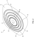
- FIG. 1 is a perspective view showing a pouch-facing side of an ostomy appliance 10, according to an embodiment
- FIG. 2 is another perspective view of the ostomy appliance 10 of FIG. 1 , showing a body-facing side of the appliance 10.
- the ostomy appliance 10 includes an ostomy hydrocolloid 11 configured to connect an ostomy pouch 210 ( FIG. 7 ) to a user.
- the ostomy hydrocolloid 11 may be, for example, any of an ostomy barrier, an ostomy faceplate or an ostomy skin barrier ring.
- the ostomy hydrocolloid 11 generally includes a backing layer 12 ( FIG. 1 ) and a skin barrier 14 ( FIG. 2 ).
- the backing layer 12 may be formed by a soft, flexible material that is generally soft and non-irritable to the user's skin, such as a nonwoven or foam material.
- an adhesive may be provided on the body-facing side 16 of the ostomy appliance 10 for adhering to the user's skin.
- the skin barrier 14 may include a known, medical grade adhesive suitable for adhering to the user's skin and sealing around a stoma.
- the ostomy appliance 10 may further include a coupling section 18 at the pouch-facing side 20 of the ostomy appliance 10.
- the coupling section 18 may be a known ostomy appliance flange configured for coupling to an ostomy pouch in a two-piece pouch configuration.
- the coupling section 18 may be a known bag-barrier interface in a one-piece pouch configuration.
- the ostomy appliance 10 includes a stoma opening 22 extending through the backing layer 12 and the skin barrier 14.
- the stoma opening 22 is configured to receive the stoma and allow for flow of stoma fluid into the ostomy pouch.
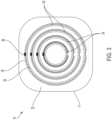
- FIG. 3 is a plan view of the body-facing side 16 of the ostomy appliance 10, according to an embodiment.
- a Radio Frequency Identification (RFID) circuit 24 is provided at the skin barrier 14.
- the RFID circuit 24 includes a RFID transponder 26 having an antenna 28 and an electrically conductive ink 30 connected in series with the antenna 28 and the RFID transponder 26.
- the RFID circuit 24 may also include a suitable device (not shown) for detecting an electrical resistance, for example, by detecting a voltage drop across the circuit.
- the RFID circuit 24 includes a plurality of the RFID circuits 24.
- the plurality of RFID circuits 24 may include, for example, at least two RFID circuits 24, and up to ten RFID circuits 24. Alternatively, a single RFID circuit 24 may be provided.
- the RFID transponder 26 is configured to operate in accordance with a local standard.
- the RFID transponder 26 may operate in accordance with Ultra-High Frequency, or UHF, RFID technology, which operates at frequency range from 902 MHz to 928 MHz.
- UHF Ultra-High Frequency
- the present disclosure is not limited to such a frequency range, however.
- the conductive ink 30 may be configured to degrade and/or change a property when exposed to moisture.
- the conductive ink 30 may be configured to absorb moisture and/or fluid and swell and become non-conductive.
- the conductive ink 30 may be dissolvable when exposed to moisture.
- the conductive ink 30 portions of the RFID circuit 24 may also be referred to as "ink jet electrodes" herein.
- the conductive ink 30 may be carbon-based, such as a carbon-based conductive ink sold by BARE CONDUCTIVE. However, other electrically conductive inks are envisioned for use in the RFID circuit 24 as well.
- the RFID circuit 24 is in a closed condition when the conductive ink 30 extends continuously between the RFID transponder 26 and the antenna 38, such that an electrical current may flow through the circuit 24.
- the RFID circuit 24 is in an open condition when at least a portion of the conductive ink 30 is dissolved, thereby preventing or limiting flow of an electrical current in the circuit.
- the RFID circuit 24 may be formed on a substrate 32 for example, by printing.
- the substrate 32 may be a release paper ( FIG. 3 ) configured to be applied over the body-facing side 16 of the ostomy appliance 10 to dispose the RFID circuit 24 on the skin barrier 14.
- the RFID circuit 24 may be manufactured independently from the ostomy hydrocolloid 11 and provided separately as an accessory for use with the ostomy hydrocolloid 11.
- the substrate 32 may be formed having the stoma opening 22, a stoma opening starter hole, or be configured to have the stoma opening 22 formed therein in a post-manufacturing step, for example, by the user.
- the substrate 32 may be the skin barrier 14 of the ostomy hydrocolloid 11 ( FIG. 2 ) such that the RFID circuit 24 is disposed directly on the skin barrier 14.
- each RFID circuit 24 of the plurality of RFID circuits 24 may be formed having a different transverse dimension.
- each RFID circuit 24 may have a radius different from the other RFID circuits 24.
- the RFID circuits 24 may be arranged concentrically relative to one another. Further still, the RFID circuits 24 may be concentric with the stoma opening 22 of the ostomy appliance 10.
- the RFID circuits 24 extend along respective substantially circular or curved paths. However, other suitably shaped paths are envisioned as well.
- the RFID circuits 24 extend 360 degrees, or substantially 360 degrees, about the stoma opening 22. In another embodiment, the RFID circuits 24 may extend along a path only partially about the stoma opening at a location where leakage is most likely to occur.
- FIG. 4 is a perspective view of a wearable device 110 according to an embodiment.
- the wearable device 110 includes a housing 112.
- the housing 112 is preferably made from a relatively lightweight, durable material.
- the material of the housing 112 is preferably a skin-friendly material as well.
- the housing 112 may include a fastener 114 configured to secure the wearable device 110 to the user, for example, on an article of clothing or other accessory.
- the fastener 114 include, but are not limited to, a clip, a hook-and-loop fastener, a button, a snap, a pin, an adhesive, a strap or other flexible material, a buckle, and the like.
- FIG. 5 is an exploded view of the wearable device 110 according to an embodiment.
- the wearable device 110 includes, for example, a controller 116, a power supply 118, such as a battery, a RFID transceiver 120 (also referred to as a RFID reader), and a first charging interface 122, such as pogo pins, for facilitating charging the power supply 118.
- the wearable device 110 may also include a wireless transceiver 124 configured to facilitate wireless communications with a personal notification device 310 ( FIG. 8 ).
- the controller 116, power supply 118, RFID transceiver 120 and wireless transceiver 124 may be operably connected to one another.
- a printed circuit board (PCB) 126 may also be provided and connected to the various components described above.
- PCB printed circuit board
- the controller 116 may be a microcontroller and may include a processor, memory and communication module.
- the processor is configured to execute program instructions stored in the memory and the communication module is configured to send or receive signals to and from the processor to carry out operations based on the program instructions.
- the wireless transceiver 124 may be configured for wireless communications according to known wireless communication standards and protocols and may communicate over known communication networks, such as personal area networks, wireless local area networks, metropolitan area networks and wide area networks. Accordingly, the wireless transceiver 124 may be configured for various wireless communications including, but not limited to, Bluetooth, Bluetooth Low Energy, Near-Field Communication, WiFi, WiMax, cellular LTE or other cellular radio communications.
- the RFID transceiver 120 is operably connected to a transceiver antenna 128, which may be formed as a coil, to facilitate RFID communications. Accordingly, the RFID transceiver 120 may be configured to transmit a first signal, such as an interrogation signal, and receive a second signal, such as a response signal as further described below.
- a first signal such as an interrogation signal
- a second signal such as a response signal as further described below.
- the wearable device 110 may further include one or more output devices 130, 132 configured to output a notification.
- the one or more output devices 130, 132 may include, for example, one or more of a visual indicator such as a light emitting device, an audio indicator such as a speaker, or a vibratory indicator such as a vibrating motor.
- the one or more output devices 130, 132 include a light emitting diode (LED) 130 and a vibrating motor 132.
- LED light emitting diode
- the wearable device 110 may further include an operating switch 134, which may be formed as pushbutton, sliding switch, rocker switch, haptic switch or other similar, suitable switch or button.
- the switch 134 may be operably coupled to the power supply 118 and function as an ON/OFF switch for the wearable device 110.
- the operating switch 134 may also function to sync or pair the wearable device 110 with the sensor 24 of the ostomy appliance 10 to facilitate communication between the one or more RFID circuits 24 and the wearable device 110.
- a separate sync or pair switch may be provided for the syncing or pairing function.
- syncing or pairing may occur when the wearable device 110 is powered on and positioned within range of the RFID circuit 24. In one embodiment, the range may be up to about 1 meter.
- the first and second signals may be transmitted between the RFID transponder 26 and the RFID transceiver 120 within a range of up to about 1 meter.
- the RFID circuit 24 is configured to receive the first signal from the RFID transceiver 120. With the RFID circuit 24 in the closed condition, the receipt of the first signal induces an electrical current through antenna 28 and conductive ink 30 to provide power to the RFID transponder 26.
- the RFID transponder 26 may transmit the second signal to the RFID transceiver 120.
- the second signal includes RFID information in the form of analog or digital data. RFID information may include, for example, identification information of the RFID transponder 26 or circuit 24 from which the second signal is transmitted.
- the conductive ink 30 may be configured to degrade and/or change a property when exposed to moisture.
- the conductive ink 30 is configured to dissolve in response to exposure to moisture. Accordingly, stoma fluid leakage from the stoma opening 22 may contact the conductive ink 30 causing the conductive ink 30 to dissolve. With at least a portion of the conductive ink 30 dissolved, the RFID circuit 24 becomes an open circuit. In the open circuit condition, electrical current may not be provided to the RFID transponder 26, and thus, the second signal may not be transmitted.
- the ostomy appliance 10 may be configured to facilitate transport of stoma fluid leakage toward the conductive ink 30 for timely leak detection.
- the hydrocolloid 11 of the ostomy appliance 10 may be configured to guide and transport stoma fluid leakage toward the conductive ink 30.
- the ostomy appliance 10 may include a wick arranged and configured to guide and transport ostomy fluid leakage toward the conductive ink 30.
- the RFID transceiver 120 is configured to receive the second signal and the controller 116 is configured to process the second signal to determine a condition of the ostomy appliance 10.
- the determined condition may indicate that stoma fluid leakage is not detected, that stoma fluid leakage is detected, and in one embodiment, an extent of the detected stoma fluid leakage.
- the extent of stoma fluid leakage may be either qualitative or quantitative, and may refer to a distance or location relative to a reference point on the ostomy hydrocolloid 11 where stoma fluid leakage has been detected.
- the reference point may be, for example the stoma opening 22 or an outer periphery of the ostomy hydrocolloid 11.
- the controller 116 may determine that stoma fluid leakage is not detected if the second signal is received from the RFID circuit 24, or each RFID circuit 24 of the plurality of RFID circuits 24, in response to transmission of the first signal.
- the controller 116 may determine that stoma fluid leakage is detected if the second signal is not received from the RFID circuit 24, or the second signal is received from less than all RFID circuits 24 of the plurality of RFID circuits 24, in response to transmission of the first signal.
- the controller 116 may determine an extent of the detected stoma fluid leakage, for example, by determining which RFID circuits 24 of the plurality of RFID have, or have not, transmitted the second signal in response to transmission of the first signal. In one embodiment, a position of the RFID circuits 24 on the ostomy hydrocolloid 11may be known, such that a quantitative indication of the extent of the stoma fluid leakage may be determined.
- an electrical resistance may be detected in the RFID circuit 24.
- the detected electrical resistance may be included as resistance information in the RFID information.
- the controller 116 may then determine whether or not a stoma fluid leak is present at an RFID circuit 24 based on the resistance information received in the second signal. For example, the controller 116 may determine that a stoma fluid leak is present if the resistance information is transmitted with the second signal. Alternatively, the controller 116 may compare the received resistance information to stored, predetermined threshold resistance information.
- the wearable device 110 is configured to output a notification based on the determined condition of the ostomy appliance 10.
- the controller 116 may be configured to output the notification by controlling one or more of the output devices 130, 132 based on the determined condition.
- the controller 116 may control the LED 130 to emit light in one more colors depending on the determined condition.
- the LED 130 may emit a green light to indicate that no stoma fluid leakage is detected, a yellow light to indicate that a non-urgent stoma fluid leak is detected which does not require immediate attention, and a red light indicating that a stoma fluid leak is detected at an extent such that the ostomy appliance should be promptly tended to.
- the "non-urgent" condition of the stoma fluid leak may be determined based on the extent of stoma fluid leak.
- the controller 116 may determine a rate of change of a stoma fluid leak, for example, by monitoring which RFID circuits 24 transmit the second signal with respect to time.
- the determined condition may be based, at least in part, on the determined rate of change.
- the LED 130 could also be controlled, for example, to blink, blink at different frequencies, or emit light at varying intensities, or any combination thereof, based on the determined condition.
- the controller 116 may control the vibrating motor 132, for example, to vibrate, not vibrate, vibrate intermittently, or at different intensities, or any combination thereof, based on the determined condition.
- an audible output device (not shown) may be controlled to emit, for example, a sound, at different time intervals, pitches, volumes, or any combination thereof, based on the determined condition. Notifications including combinations of the above may be output as well.
- FIG. 6 shows examples of the ostomy hydrocolloid 11 and the wearable device 110 of the ostomy appliance 10, according to an embodiment.
- a charging device 136 may be provided having a second charging interface (not shown) configured for electrical connection to the first charging interface 122 of the wearable device 110, to charge the power supply 118.
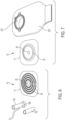
- FIG. 7 shows the ostomy hydrocolloid 11 and an ostomy pouch 210 of the ostomy appliance 10, according to an embodiment.
- the ostomy pouch 210 includes an inlet opening 212 configured to allow stoma fluid to be received in an internal collection area.
- the inlet opening 212 may be disposed in fluid communication with the stoma opening 22.
- the pouch 210 may include a pouch coupling section 214 configured for coupling to the coupling section 18 of the ostomy hydrocolloid 11.
- FIG. 8 schematically shows a personal notification device 310 communicatively connected to the ostomy appliance 10, according to an embodiment.
- the personal notification device 310 may be included as a component of the ostomy appliance 10.
- the personal notification device 310 may be communicatively connected to the wearable device 110, for example, over a wireless communication interface by way of the wireless transceiver 124.
- the personal notification device 310 may be a mobile communication device, such as a smart phone or other mobile phone.
- the personal notification device 310 may be another mobile communication device, a portable electronic device, or other electronic device configured for communication, directly or indirectly, with the wearable device 110.
- Such devices may include, but are not limited to, tablets, laptop computers, desktop computers, smart speakers, connected wearable accessories such as fitness trackers, smart watches and the like, smart televisions, personal digital assistants and the like.
- the wearable device 110 may be paired, synced, or otherwise communicatively connected to the personal notification device 310 with a known pairing or syncing operation, which may be initiated, for example, by operation of the operating switch 134.
- the personal notification device 310 may determine the condition of the ostomy appliance 10 and output a notification based on the determined condition, in a manner similar to that described above with respect to the controller 116.
- the wearable device 110 may transmit the determined condition of the ostomy appliance 10 to the personal notification device 310.
- the personal notification device 310 may include one or more output devices, such as those described above for example, for outputting a notification based on the determined condition. It is further envisioned that different, or additional, notifications based on the determined condition may be provided on a display screen 312 of the personal notification device 310. For example, graphics, animations and the like may be provided as a notification on the display screen.
- the personal notification device 310 may receive the determined condition, or determine the condition, of the ostomy appliance 10 at predetermined time intervals. Alternatively, or in addition, a user may operate the personal notification device 310 to request the determined condition from the wearable device 110 or to determine the condition.
- the personal notification device 310 may perform functions according to a smartphone application directed to the ostomy appliance 10.
- the smartphone application may include program instructions stored in a memory unit of the smartphone which are configured to be executed by a processor of the smartphone to control the smartphone to perform the functions.
- the smartphone may be controlled to generate and output the notification.
- the smartphone may also be controlled to store additional data and enable further communications.
- the smartphone may be configured to track leaks or degradation of the ostomy hydrocolloid 11, behaviors and activities that could potentially affect wear time, including, but not limited to: pouch changes, diet, leakage occurrence, gas occurrence and physical activity.
- the smartphone may be configured to provide a platform to share practices and advice from other users and clinicians.
- the smartphone may be configured to allow for communication with other information sources, for example, to access video tutorials providing additional education and instruction on managing a stoma.
- the smartphone may be configured to allow for pictures to be taken and stored of the stoma and skin health.
- the smartphone may be configured to facilitate contact with a wound, ostomy and continence (WOC) nurse (also referred to as an enterostomal therapy (ET) nurse), for example, to troubleshoot or share stoma and skin health conditions.
- WOC wound, ostomy and continence
- ET enterostomal therapy
- the smartphone may be configured to allow for ordering or automatic re-ordering of an ostomy appliance 10 or related supplies when a determination is made that such supplies are running low.
- the smartphone may be configured to provide usage and patient data to, for example, the ostomy appliance manufacturer, such as marketing, research and product support teams.
- usage and data may be provided, for example, after a user opts-in, and the data may be provided securely, anonymously, and in accordance with local privacy laws and regulations, to support health economics.
- a smartphone application executed to control functions of a smartphone according to the examples above.
- a similar software application could be executed by a tablet or other portable device, a remote server configured to be accessed by the user through a known communications interface, or at a personal computing device, such as a laptop or desktop computer, or some combination of the above.
- FIGS. 9A and 9B show examples of the RFID circuit 24 being applied to the ostomy hydrocolloid 11.
- the RFID circuit 24 may be disposed on the substrate 32 ( FIG. 9A ).
- the RFID circuit 24 may be applied to the body-facing side 16 of the ostomy hydrocolloid 11, and a release layer 34 may be removed ( FIG. 9B ) to expose an adhesive on the RFID circuit 24 for adhering to a user's skin.
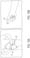
- FIGS. 10A and 10B show a user setting up the ostomy appliance 10 for use, according to an embodiment.
- the ostomy appliance 10 including the ostomy pouch 210
- the wearable device 110 is powered on and communicatively coupled to the ostomy appliance 10, for example, to the one or more RFID circuit 24.
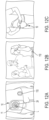
- FIGS. 11A-11C show examples the ostomy appliance 10, in use, configured to detect stoma fluid leakage.
- FIG. 11A shows the ostomy appliance 10, including the ostomy pouch 210 and the wearable device 110 connected to the user.
- FIG. 11B shows the user in a social setting and
- FIG. 11C shows ostomy appliance 10 with a stoma fluid leakage 'L' forming along the ostomy hydrocolloid 11.
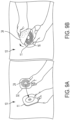
- FIGS. 12A-12C show examples of a user tending to the ostomy appliance 10 in response to receiving a notification of stoma fluid leak 'L'.
- a stoma fluid leak 'L' is detected by a plurality of the RFID circuits 24 and a notification is provided by the wearable device 110.
- the user discreetly senses the notification.
- the user tends to the ostomy appliance 10.
Landscapes
- Health & Medical Sciences (AREA)
- Heart & Thoracic Surgery (AREA)
- Orthopedic Medicine & Surgery (AREA)
- Vascular Medicine (AREA)
- Nursing (AREA)
- Life Sciences & Earth Sciences (AREA)
- Engineering & Computer Science (AREA)
- Biomedical Technology (AREA)
- Animal Behavior & Ethology (AREA)
- Epidemiology (AREA)
- Veterinary Medicine (AREA)
- Public Health (AREA)
- General Health & Medical Sciences (AREA)
- Physics & Mathematics (AREA)
- General Physics & Mathematics (AREA)
- Chemical & Material Sciences (AREA)
- Dispersion Chemistry (AREA)
- Orthopedics, Nursing, And Contraception (AREA)
Description
- The following description relates generally to an ostomy appliance having a conductive ink circuit for detecting leakage.
- An ostomy pouch includes opposing sidewalls defining an internal collection area. One of the sidewalls is provided with an inlet opening to receive a stoma, and means to secure the pouch to the user. Such means include, for example, an ostomy barrier, faceplate or skin barrier ring which may be connected to or formed integrally with the sidewall having the inlet opening. The ostomy barrier (or faceplate or barrier ring) may include adhesive on a skin-facing side to seal against the user's skin in an area surrounding the stoma. Such a system is intended to prevent or limit leakage of bodily fluid discharged from the stoma through the stoma/barrier/pouch environment.
- However, the seal formed between the ostomy barrier and the user may weaken, for example, with time, movement, improper installation and/or application of an external force, and thus, become susceptible to leaking. Often times, the user is unaware of or cannot easily assess an extent of weakening in the seal. Thus, a user is typically not aware of a weakened seal, and consequently, the risk of leakage, until a fluid discharged from the stoma leaks through to an exterior of the seal (i.e., the barrier) and becomes undesirably exposed to an external environment outside of the stoma/barrier/pouch environment.
- Efforts have been made in the art to detect leakage of fluid before the fluid escapes to the exterior environment. For example,
WO 2018/028756 ("WO `756") discloses an ostomy appliance having a signal generator adapted to give a user or a health care professional a warning in time to change the appliance before leakage occurs by predetermining leakage or potential leakage of stomal fluids. In WO' 756, a second material may be configured to dissipate in response to being exposed to stomal fluids and a signal generator, generally disposed under or within the second material, may set off an indicator signal when dissipation of the second material reaches a pre-defined threshold value. - In
US Pat. Appl. Pub. No. 2017/0140103 ("US '103"), a parameter sensor that uses ink jet electrodes printed on paper can be used to measure leakage. The sensor paper is placed at a site of ostomy bag attachment to the stoma with the sensor paper surrounding the stoma. As the paper gets wet, from leakage, the electrodes change resistance and report this to a communicator. - Another system for detecting leakage is described in
US 9,216,104 - However, the systems above may still require frequent visual or manual monitoring, may be undesirably complex, or may not be suitably accurate.
- Other systems have been proposed for sensing wetness, for example, as described in
US Pat. No. 9,782,302 -
WO2007098762A1 discloses a method and dressing for detecting detachment of the dressing, which is applied to a surface of an at least partly electrically conductive object. The dressing comprises an adhesive for attaching the dressing to the electrically conductive object and at least two electrodes arranged in a distance from the electrically conductive object. A voltage is applied to the first and second electrode establishing an electrical circuit comprising a first capacitor between the first electrode and the electrically conductive object and a second capacitor between the second electrode and the electrically conductive object. Changes of the capacitance between at least one of the first and the second electrode and the electrically conductive object are detected, and an alarm is activated when the changes of the capacitance reach a predetermined value. This advantageously provides a method whereby a leak can be detected quickly. -
US2017140103A1 discloses systems and methods for providing comprehensive care for stoma patients. According to one embodiment, a system for providing comprehensive care for a stoma patient includes: a sensor device for detecting a fill level of an ostomy bag fitted over and around a stoma, wherein the sensor device is configured to sense one or more parameters of an effluent received in the bag; communicating the measurements to a stoma care management software application for formatting and visualization on a patient mobile device; and transferring the formatted data to an interactive wireless stoma care management platform, wherein the platform is configured to maintain a patient related database and to periodically advise the patient of needed actions as well as to provide reminders, advice and coaching. -
WO2017023794A1 discloses a urine collection apparatus and monitoring device. The urine collection apparatus includes a collection reservoir and a diverter for controlling flow of urine to a first passageway in a first position and to a second passageway in a second position, wherein the first passageway is fluidly interconnected to the collection reservoir. The urine collection apparatus may include a cartridge having an internal chamber and inlet and outlet members, wherein the inlet member is selectively, fluidly interconnectable to the second passageway, and wherein the outlet member is selectively, fluidly interconnectable to the collection reservoir. The monitoring device is interconnectable with the cartridge and monitors a volume of urine collected. The cartridge may be received within the monitoring device. The monitoring device may include a light source for emitting a light signal and a light detector array for detecting the light signal and outputting signals to determine urine volume. - Accordingly, it is desirable to provide an ostomy appliance, such as an ostomy hydrocolloid or ostomy pouch having such an ostomy hydrocolloid, in which leakage may be detected using a conductive ink circuit. It is also desirable to provide an ostomy appliance in which a notification may be provided to the user based on the leakage detection, before the leakage reaches the exterior environment. It is also desirable to provide an ostomy appliance in which an extent of leakage may be detected.
- The present invention relates to an ostomy appliance as set out in the claims.
- Other objects, features, and advantages of the disclosure will be apparent from the following description, taken in conjunction with the accompanying sheets of drawings, wherein like numerals refer to like parts, elements, components, steps, and processes.
-
-
FIG. 1 is a perspective view of an ostomy appliance, according to an embodiment; -
FIG. 2 is another perspective view of the ostomy appliance ofFIG. 1 ; -
FIG. 3 is a plan view showing a body-facing side of the ostomy appliance ofFIG. 2 , according to an embodiment; -
FIG. 4 is a perspective view of a wearable device, according to an embodiment; -
FIG. 5 is an exploded view of the wearable device, according to an embodiment; -
FIG. 6 shows an ostomy hydrocolloid and the wearable device of the ostomy appliance, according to an embodiment; -
FIG. 7 shows the ostomy hydrocolloid and an ostomy pouch of the ostomy appliance, according to an embodiment; -
FIG. 8 schematically shows a personal notification device communicatively connected to the ostomy appliance, according to an embodiment; -
FIGS. 9A-9B show the RFID circuit being applied to the ostomy hydrocolloid, according to an embodiment; -
FIGS. 10A-10B show a user setting up the ostomy appliance for use, according to an embodiment; -
FIGS. 11A-11C show examples the ostomy appliance, in use, configured to detect stoma fluid leakage; and -
FIGS. 12A-12C show examples of a user tending to the ostomy appliance in response to receiving a notification of stoma fluid leakage. - While the present disclosure is susceptible of embodiment in various forms, there is shown in the drawings and will hereinafter be described one or more embodiments with the understanding that the present disclosure is to be considered illustrative only and is not intended to limit the disclosure to any specific embodiment described or illustrated.
-
FIG. 1 is a perspective view showing a pouch-facing side of anostomy appliance 10, according to an embodiment, andFIG. 2 is another perspective view of theostomy appliance 10 ofFIG. 1 , showing a body-facing side of theappliance 10. In one embodiment, theostomy appliance 10 includes anostomy hydrocolloid 11 configured to connect an ostomy pouch 210 (FIG. 7 ) to a user. Theostomy hydrocolloid 11 may be, for example, any of an ostomy barrier, an ostomy faceplate or an ostomy skin barrier ring. In one embodiment, theostomy hydrocolloid 11 generally includes a backing layer 12 (FIG. 1 ) and a skin barrier 14 (FIG. 2 ). Thebacking layer 12 may be formed by a soft, flexible material that is generally soft and non-irritable to the user's skin, such as a nonwoven or foam material. In one embodiment, an adhesive may be provided on the body-facingside 16 of theostomy appliance 10 for adhering to the user's skin. Theskin barrier 14 may include a known, medical grade adhesive suitable for adhering to the user's skin and sealing around a stoma. - The
ostomy appliance 10 may further include acoupling section 18 at the pouch-facingside 20 of theostomy appliance 10. In one embodiment, thecoupling section 18 may be a known ostomy appliance flange configured for coupling to an ostomy pouch in a two-piece pouch configuration. In another embodiment, thecoupling section 18 may be a known bag-barrier interface in a one-piece pouch configuration. - The
ostomy appliance 10 includes astoma opening 22 extending through thebacking layer 12 and theskin barrier 14. Thestoma opening 22 is configured to receive the stoma and allow for flow of stoma fluid into the ostomy pouch. -
FIG. 3 is a plan view of the body-facingside 16 of theostomy appliance 10, according to an embodiment. With reference toFIGS. 2 and3 , a Radio Frequency Identification (RFID)circuit 24 is provided at theskin barrier 14. In one embodiment, theRFID circuit 24 includes aRFID transponder 26 having anantenna 28 and an electricallyconductive ink 30 connected in series with theantenna 28 and theRFID transponder 26. In one embodiment, theRFID circuit 24 may also include a suitable device (not shown) for detecting an electrical resistance, for example, by detecting a voltage drop across the circuit. In one embodiment, theRFID circuit 24 includes a plurality of theRFID circuits 24. In one embodiment, the plurality ofRFID circuits 24 may include, for example, at least twoRFID circuits 24, and up to tenRFID circuits 24. Alternatively, asingle RFID circuit 24 may be provided. - In one embodiment, the
RFID transponder 26 is configured to operate in accordance with a local standard. For example, in the United States, theRFID transponder 26 may operate in accordance with Ultra-High Frequency, or UHF, RFID technology, which operates at frequency range from 902 MHz to 928 MHz. The present disclosure is not limited to such a frequency range, however. - The
conductive ink 30 may be configured to degrade and/or change a property when exposed to moisture. For example, theconductive ink 30 may be configured to absorb moisture and/or fluid and swell and become non-conductive. In an embodiment, theconductive ink 30 may be dissolvable when exposed to moisture. Theconductive ink 30 portions of theRFID circuit 24 may also be referred to as "ink jet electrodes" herein. In one embodiment, theconductive ink 30 may be carbon-based, such as a carbon-based conductive ink sold by BARE CONDUCTIVE. However, other electrically conductive inks are envisioned for use in theRFID circuit 24 as well. TheRFID circuit 24 is in a closed condition when theconductive ink 30 extends continuously between theRFID transponder 26 and the antenna 38, such that an electrical current may flow through thecircuit 24. TheRFID circuit 24 is in an open condition when at least a portion of theconductive ink 30 is dissolved, thereby preventing or limiting flow of an electrical current in the circuit. - The
RFID circuit 24 may be formed on asubstrate 32 for example, by printing. In one embodiment, thesubstrate 32 may be a release paper (FIG. 3 ) configured to be applied over the body-facingside 16 of theostomy appliance 10 to dispose theRFID circuit 24 on theskin barrier 14. Accordingly, theRFID circuit 24 may be manufactured independently from theostomy hydrocolloid 11 and provided separately as an accessory for use with theostomy hydrocolloid 11. In one embodiment, thesubstrate 32 may be formed having thestoma opening 22, a stoma opening starter hole, or be configured to have thestoma opening 22 formed therein in a post-manufacturing step, for example, by the user. In another embodiment, thesubstrate 32 may be theskin barrier 14 of the ostomy hydrocolloid 11 (FIG. 2 ) such that theRFID circuit 24 is disposed directly on theskin barrier 14. - In one embodiment, each
RFID circuit 24 of the plurality ofRFID circuits 24 may be formed having a different transverse dimension. For example, eachRFID circuit 24 may have a radius different from theother RFID circuits 24. In one embodiment, theRFID circuits 24 may be arranged concentrically relative to one another. Further still, theRFID circuits 24 may be concentric with the stoma opening 22 of theostomy appliance 10. In one embodiment, theRFID circuits 24 extend along respective substantially circular or curved paths. However, other suitably shaped paths are envisioned as well. In one embodiment, theRFID circuits 24 extend 360 degrees, or substantially 360 degrees, about thestoma opening 22. In another embodiment, theRFID circuits 24 may extend along a path only partially about the stoma opening at a location where leakage is most likely to occur. -
FIG. 4 is a perspective view of awearable device 110 according to an embodiment. In one embodiment, thewearable device 110 includes ahousing 112. Thehousing 112 is preferably made from a relatively lightweight, durable material. The material of thehousing 112 is preferably a skin-friendly material as well. Thehousing 112 may include afastener 114 configured to secure thewearable device 110 to the user, for example, on an article of clothing or other accessory. Examples of thefastener 114 include, but are not limited to, a clip, a hook-and-loop fastener, a button, a snap, a pin, an adhesive, a strap or other flexible material, a buckle, and the like. -
FIG. 5 is an exploded view of thewearable device 110 according to an embodiment. Thewearable device 110 includes, for example, acontroller 116, apower supply 118, such as a battery, a RFID transceiver 120 (also referred to as a RFID reader), and afirst charging interface 122, such as pogo pins, for facilitating charging thepower supply 118. Thewearable device 110 may also include awireless transceiver 124 configured to facilitate wireless communications with a personal notification device 310 (FIG. 8 ). In one embodiment, thecontroller 116,power supply 118,RFID transceiver 120 andwireless transceiver 124 may be operably connected to one another. In one embodiment, a printed circuit board (PCB) 126 may also be provided and connected to the various components described above. - The
controller 116 may be a microcontroller and may include a processor, memory and communication module. The processor is configured to execute program instructions stored in the memory and the communication module is configured to send or receive signals to and from the processor to carry out operations based on the program instructions. - In one embodiment, the
wireless transceiver 124 may be configured for wireless communications according to known wireless communication standards and protocols and may communicate over known communication networks, such as personal area networks, wireless local area networks, metropolitan area networks and wide area networks. Accordingly, thewireless transceiver 124 may be configured for various wireless communications including, but not limited to, Bluetooth, Bluetooth Low Energy, Near-Field Communication, WiFi, WiMax, cellular LTE or other cellular radio communications. - The
RFID transceiver 120 is operably connected to atransceiver antenna 128, which may be formed as a coil, to facilitate RFID communications. Accordingly, theRFID transceiver 120 may be configured to transmit a first signal, such as an interrogation signal, and receive a second signal, such as a response signal as further described below. - In one embodiment, the
wearable device 110 may further include one ormore output devices more output devices more output devices motor 132. However, it is understood that other, additional or fewer output devices, or combinations of output devices, are envisioned as well. - In one embodiment, the
wearable device 110 may further include anoperating switch 134, which may be formed as pushbutton, sliding switch, rocker switch, haptic switch or other similar, suitable switch or button. Theswitch 134 may be operably coupled to thepower supply 118 and function as an ON/OFF switch for thewearable device 110. In one embodiment, theoperating switch 134 may also function to sync or pair thewearable device 110 with thesensor 24 of theostomy appliance 10 to facilitate communication between the one ormore RFID circuits 24 and thewearable device 110. In another embodiment, a separate sync or pair switch may be provided for the syncing or pairing function. In one embodiment, syncing or pairing may occur when thewearable device 110 is powered on and positioned within range of theRFID circuit 24. In one embodiment, the range may be up to about 1 meter. Thus, in one embodiment, the first and second signals may be transmitted between theRFID transponder 26 and theRFID transceiver 120 within a range of up to about 1 meter. - In the embodiments above, the
RFID circuit 24 is configured to receive the first signal from theRFID transceiver 120. With theRFID circuit 24 in the closed condition, the receipt of the first signal induces an electrical current throughantenna 28 andconductive ink 30 to provide power to theRFID transponder 26. TheRFID transponder 26 may transmit the second signal to theRFID transceiver 120. The second signal includes RFID information in the form of analog or digital data. RFID information may include, for example, identification information of theRFID transponder 26 orcircuit 24 from which the second signal is transmitted. - The
conductive ink 30 may be configured to degrade and/or change a property when exposed to moisture. In an embodiment, theconductive ink 30 is configured to dissolve in response to exposure to moisture. Accordingly, stoma fluid leakage from thestoma opening 22 may contact theconductive ink 30 causing theconductive ink 30 to dissolve. With at least a portion of theconductive ink 30 dissolved, theRFID circuit 24 becomes an open circuit. In the open circuit condition, electrical current may not be provided to theRFID transponder 26, and thus, the second signal may not be transmitted. In some embodiments, theostomy appliance 10 may be configured to facilitate transport of stoma fluid leakage toward theconductive ink 30 for timely leak detection. For example, thehydrocolloid 11 of theostomy appliance 10 may be configured to guide and transport stoma fluid leakage toward theconductive ink 30. In another example, theostomy appliance 10 may include a wick arranged and configured to guide and transport ostomy fluid leakage toward theconductive ink 30. - The
RFID transceiver 120 is configured to receive the second signal and thecontroller 116 is configured to process the second signal to determine a condition of theostomy appliance 10. The determined condition may indicate that stoma fluid leakage is not detected, that stoma fluid leakage is detected, and in one embodiment, an extent of the detected stoma fluid leakage. The extent of stoma fluid leakage may be either qualitative or quantitative, and may refer to a distance or location relative to a reference point on theostomy hydrocolloid 11 where stoma fluid leakage has been detected. The reference point may be, for example thestoma opening 22 or an outer periphery of theostomy hydrocolloid 11. - In one embodiment, the
controller 116 may determine that stoma fluid leakage is not detected if the second signal is received from theRFID circuit 24, or eachRFID circuit 24 of the plurality ofRFID circuits 24, in response to transmission of the first signal. - In one embodiment, the
controller 116 may determine that stoma fluid leakage is detected if the second signal is not received from theRFID circuit 24, or the second signal is received from less than allRFID circuits 24 of the plurality ofRFID circuits 24, in response to transmission of the first signal. - In one embodiment, the
controller 116 may determine an extent of the detected stoma fluid leakage, for example, by determining whichRFID circuits 24 of the plurality of RFID have, or have not, transmitted the second signal in response to transmission of the first signal. In one embodiment, a position of theRFID circuits 24 on the ostomy hydrocolloid 11may be known, such that a quantitative indication of the extent of the stoma fluid leakage may be determined. - In one embodiment, as the
conductive ink 30 dissolves, an electrical resistance may be detected in theRFID circuit 24. In one embodiment, the detected electrical resistance may be included as resistance information in the RFID information. Thecontroller 116 may then determine whether or not a stoma fluid leak is present at anRFID circuit 24 based on the resistance information received in the second signal. For example, thecontroller 116 may determine that a stoma fluid leak is present if the resistance information is transmitted with the second signal. Alternatively, thecontroller 116 may compare the received resistance information to stored, predetermined threshold resistance information. - In one embodiment, the
wearable device 110 is configured to output a notification based on the determined condition of theostomy appliance 10. For example, thecontroller 116 may be configured to output the notification by controlling one or more of theoutput devices controller 116 may control theLED 130 to emit light in one more colors depending on the determined condition. In one embodiment, theLED 130 may emit a green light to indicate that no stoma fluid leakage is detected, a yellow light to indicate that a non-urgent stoma fluid leak is detected which does not require immediate attention, and a red light indicating that a stoma fluid leak is detected at an extent such that the ostomy appliance should be promptly tended to. The "non-urgent" condition of the stoma fluid leak may be determined based on the extent of stoma fluid leak. In one embodiment, thecontroller 116 may determine a rate of change of a stoma fluid leak, for example, by monitoring whichRFID circuits 24 transmit the second signal with respect to time. In one embodiment, the determined condition may be based, at least in part, on the determined rate of change. - The
LED 130 could also be controlled, for example, to blink, blink at different frequencies, or emit light at varying intensities, or any combination thereof, based on the determined condition. Alternatively, or in addition, thecontroller 116 may control the vibratingmotor 132, for example, to vibrate, not vibrate, vibrate intermittently, or at different intensities, or any combination thereof, based on the determined condition. Similarly, an audible output device (not shown) may be controlled to emit, for example, a sound, at different time intervals, pitches, volumes, or any combination thereof, based on the determined condition. Notifications including combinations of the above may be output as well. -
FIG. 6 shows examples of theostomy hydrocolloid 11 and thewearable device 110 of theostomy appliance 10, according to an embodiment. In one embodiment, acharging device 136 may be provided having a second charging interface (not shown) configured for electrical connection to thefirst charging interface 122 of thewearable device 110, to charge thepower supply 118. -
FIG. 7 shows theostomy hydrocolloid 11 and anostomy pouch 210 of theostomy appliance 10, according to an embodiment. Theostomy pouch 210 includes aninlet opening 212 configured to allow stoma fluid to be received in an internal collection area. Theinlet opening 212 may be disposed in fluid communication with thestoma opening 22. In one embodiment, thepouch 210 may include a pouch coupling section 214 configured for coupling to thecoupling section 18 of theostomy hydrocolloid 11. -
FIG. 8 schematically shows apersonal notification device 310 communicatively connected to theostomy appliance 10, according to an embodiment. In one embodiment, thepersonal notification device 310 may be included as a component of theostomy appliance 10. In one embodiment, thepersonal notification device 310 may be communicatively connected to thewearable device 110, for example, over a wireless communication interface by way of thewireless transceiver 124. - In one embodiment, the
personal notification device 310 may be a mobile communication device, such as a smart phone or other mobile phone. Alternatively, or in addition, thepersonal notification device 310 may be another mobile communication device, a portable electronic device, or other electronic device configured for communication, directly or indirectly, with thewearable device 110. Such devices may include, but are not limited to, tablets, laptop computers, desktop computers, smart speakers, connected wearable accessories such as fitness trackers, smart watches and the like, smart televisions, personal digital assistants and the like. - In one embodiment, the
wearable device 110 may be paired, synced, or otherwise communicatively connected to thepersonal notification device 310 with a known pairing or syncing operation, which may be initiated, for example, by operation of theoperating switch 134. - In one embodiment, the
personal notification device 310 may determine the condition of theostomy appliance 10 and output a notification based on the determined condition, in a manner similar to that described above with respect to thecontroller 116. In another embodiment, thewearable device 110 may transmit the determined condition of theostomy appliance 10 to thepersonal notification device 310. - In one embodiment, the
personal notification device 310 may include one or more output devices, such as those described above for example, for outputting a notification based on the determined condition. It is further envisioned that different, or additional, notifications based on the determined condition may be provided on adisplay screen 312 of thepersonal notification device 310. For example, graphics, animations and the like may be provided as a notification on the display screen. - In one embodiment, the
personal notification device 310 may receive the determined condition, or determine the condition, of theostomy appliance 10 at predetermined time intervals. Alternatively, or in addition, a user may operate thepersonal notification device 310 to request the determined condition from thewearable device 110 or to determine the condition. - In one embodiment, the
personal notification device 310, embodied as a smartphone, may perform functions according to a smartphone application directed to theostomy appliance 10. The smartphone application may include program instructions stored in a memory unit of the smartphone which are configured to be executed by a processor of the smartphone to control the smartphone to perform the functions. For example, the smartphone may be controlled to generate and output the notification. The smartphone may also be controlled to store additional data and enable further communications. For example, the smartphone may be configured to track leaks or degradation of theostomy hydrocolloid 11, behaviors and activities that could potentially affect wear time, including, but not limited to: pouch changes, diet, leakage occurrence, gas occurrence and physical activity. - In one embodiment, the smartphone may be configured to provide a platform to share practices and advice from other users and clinicians. In one embodiment, the smartphone may be configured to allow for communication with other information sources, for example, to access video tutorials providing additional education and instruction on managing a stoma. In one embodiment, the smartphone may be configured to allow for pictures to be taken and stored of the stoma and skin health. In one embodiment the smartphone may be configured to facilitate contact with a wound, ostomy and continence (WOC) nurse (also referred to as an enterostomal therapy (ET) nurse), for example, to troubleshoot or share stoma and skin health conditions. In one embodiment, the smartphone may be configured to allow for ordering or automatic re-ordering of an
ostomy appliance 10 or related supplies when a determination is made that such supplies are running low. In one embodiment, the smartphone may be configured to provide usage and patient data to, for example, the ostomy appliance manufacturer, such as marketing, research and product support teams. In one embodiment, such usage and data may be provided, for example, after a user opts-in, and the data may be provided securely, anonymously, and in accordance with local privacy laws and regulations, to support health economics. - Those having ordinary skill in the art will appreciate that the present disclosure is not limited to a smartphone application executed to control functions of a smartphone according to the examples above. For instance, it is also envisioned that a similar software application could be executed by a tablet or other portable device, a remote server configured to be accessed by the user through a known communications interface, or at a personal computing device, such as a laptop or desktop computer, or some combination of the above.
-
FIGS. 9A and 9B show examples of theRFID circuit 24 being applied to theostomy hydrocolloid 11. In one embodiment, theRFID circuit 24 may be disposed on the substrate 32 (FIG. 9A ). TheRFID circuit 24 may be applied to the body-facingside 16 of theostomy hydrocolloid 11, and arelease layer 34 may be removed (FIG. 9B ) to expose an adhesive on theRFID circuit 24 for adhering to a user's skin. -
FIGS. 10A and 10B show a user setting up theostomy appliance 10 for use, according to an embodiment. For example, inFIG. 10A , theostomy appliance 10, including theostomy pouch 210, is secured to the user, and inFIG. 10B , thewearable device 110 is powered on and communicatively coupled to theostomy appliance 10, for example, to the one ormore RFID circuit 24. -
FIGS. 11A-11C show examples theostomy appliance 10, in use, configured to detect stoma fluid leakage. For example,FIG. 11A shows theostomy appliance 10, including theostomy pouch 210 and thewearable device 110 connected to the user.FIG. 11B shows the user in a social setting andFIG. 11C showsostomy appliance 10 with a stoma fluid leakage 'L' forming along theostomy hydrocolloid 11. -
FIGS. 12A-12C show examples of a user tending to theostomy appliance 10 in response to receiving a notification of stoma fluid leak 'L'. InFIG. 12A , a stoma fluid leak 'L' is detected by a plurality of theRFID circuits 24 and a notification is provided by thewearable device 110. InFIG. 12B , the user discreetly senses the notification. InFIG. 12C , the user tends to theostomy appliance 10. - In the present disclosure, the words "a" or "an" are to be taken to include both the singular and the plural. Conversely, any reference to plural items shall, where appropriate, include the singular. In additions, various features described with respect to any of the embodiments above may be used together, implemented in, or replace features in any of the other embodiments described above.
Claims (12)
- An ostomy appliance (10) comprising:a hydrocolloid (11); anda leak detection system comprising at least one inkjet electrode arranged on the hydrocolloid (11), characterised in that wherein the leak detection system is configured to measure an electrical current flowing through the at least one ink jet electrode, that the leak detection system is configured to detect the ostomy leakage by measuring a change in electrical current flowing through the at least one ink jet electrode, and that the at least one inkjet electrode is configured to reduce a conductivity when exposed to an ostomy leakage.
- The ostomy appliance (10) of claim 1, wherein the leak detection system further comprises at least one Radio Frequency Identification (RFID) circuit (24) comprising a RFID transponder (26) having an antenna (28), wherein the at least one ink jet electrode is connected in series with the antenna and the RFID transponder, wherein the RFID circuit is configured to form a closed circuit with the at least one ink jet electrode extending between the RFID transponder and the antenna.
- The ostomy appliance (10) of claim 2, wherein the at least one ink jet electrode is formed from a conductive ink (30), wherein the at least one inkjet electrode dissolves when exposed to the ostomy leakage, wherein the RFID circuit is in an open condition when at least a portion of the at least one ink jet electrode is dissolved.
- The ostomy appliance (10) of claim 2, wherein the at least one ink jet electrode is configured to absorb fluid when exposed to the ostomy leakage and swell, wherein the conductivity is reduced when the at least one ink jet electrode absorbs fluid and swells.
- The ostomy appliance (10) of any of claims 2-4, further comprising a wearable device (110) communicatively connected to the at least one RFID circuit, the wearable device comprising:a housing (112);a power supply (118);a controller (116) operably connected to the power supply; andan RFID transceiver (120) operably connected to a transceiver antenna (128) and the controller.
- The ostomy appliance (10) of claim 5, wherein the RFID transceiver is configured to transmit a first signal, and wherein the RFID transponder is configured to transmit a second signal in response receiving the first signal with the RFID circuit in a closed condition and is not configured to transmit the second signal with the RFID circuit in the opened condition.
- The ostomy appliance (10) of claim 6, wherein the controller is configured to determine a leakage condition of the ostomy appliance based on the second signal.
- The ostomy appliance (10) of claim 7, wherein the wearable device further comprises an output device (130, 132) configured to output a notification based on the determined leakage condition of the ostomy appliance.
- The ostomy appliance (10) of any of claims 5-7, wherein the wearable device further comprises a wireless transceiver (124) .
- The ostomy appliance (10) of claim 9, wherein the ostomy appliance further comprises a personal notification device (310) communicatively connected to the wearable device via the wireless transceiver.
- The ostomy appliance (10) of claim 10, wherein the personal notification device is configured to output a notification based on the determined condition.
- The ostomy appliance (10) of any of claims 10 or 11, wherein the personal notification device is a smartphone.
Priority Applications (1)
| Application Number | Priority Date | Filing Date | Title |
|---|---|---|---|
| EP24152610.2A EP4335417A2 (en) | 2018-10-09 | 2019-10-03 | Ostomy appliance having conductive ink circuit for leakage detection |
Applications Claiming Priority (2)
| Application Number | Priority Date | Filing Date | Title |
|---|---|---|---|
| US201862743233P | 2018-10-09 | 2018-10-09 | |
| PCT/US2019/054484 WO2020076607A1 (en) | 2018-10-09 | 2019-10-03 | Ostomy appliance having conductive ink circuit for leakage detection |
Related Child Applications (2)
| Application Number | Title | Priority Date | Filing Date |
|---|---|---|---|
| EP24152610.2A Division-Into EP4335417A2 (en) | 2018-10-09 | 2019-10-03 | Ostomy appliance having conductive ink circuit for leakage detection |
| EP24152610.2A Division EP4335417A2 (en) | 2018-10-09 | 2019-10-03 | Ostomy appliance having conductive ink circuit for leakage detection |
Publications (2)
| Publication Number | Publication Date |
|---|---|
| EP3863575A1 EP3863575A1 (en) | 2021-08-18 |
| EP3863575B1 true EP3863575B1 (en) | 2024-05-08 |
Family
ID=68296817
Family Applications (2)
| Application Number | Title | Priority Date | Filing Date |
|---|---|---|---|
| EP24152610.2A Pending EP4335417A2 (en) | 2018-10-09 | 2019-10-03 | Ostomy appliance having conductive ink circuit for leakage detection |
| EP19791093.8A Active EP3863575B1 (en) | 2018-10-09 | 2019-10-03 | Ostomy appliance having conductive ink circuit for leakage detection |
Family Applications Before (1)
| Application Number | Title | Priority Date | Filing Date |
|---|---|---|---|
| EP24152610.2A Pending EP4335417A2 (en) | 2018-10-09 | 2019-10-03 | Ostomy appliance having conductive ink circuit for leakage detection |
Country Status (7)
| Country | Link |
|---|---|
| US (1) | US20210338471A1 (en) |
| EP (2) | EP4335417A2 (en) |
| CN (1) | CN112969434B (en) |
| AU (1) | AU2019359129A1 (en) |
| CA (1) | CA3115737A1 (en) |
| DK (1) | DK3863575T3 (en) |
| WO (1) | WO2020076607A1 (en) |
Families Citing this family (39)
| Publication number | Priority date | Publication date | Assignee | Title |
|---|---|---|---|---|
| CN102281840B (en) | 2007-06-12 | 2016-05-11 | 康沃特克科技公司 | Ostomy appliance |
| US10285847B2 (en) | 2011-09-29 | 2019-05-14 | Convatec Technologies Inc. | Ostomy pouch with filtering system |
| US10531977B2 (en) | 2014-04-17 | 2020-01-14 | Coloplast A/S | Thermoresponsive skin barrier appliances |
| EP3134040B1 (en) | 2014-04-24 | 2021-03-10 | ConvaTec Technologies Inc. | Ostomy pouch filter system |
| US11406525B2 (en) | 2017-11-09 | 2022-08-09 | 11 Health And Technologies Limited | Ostomy monitoring system and method |
| US11612508B2 (en) | 2017-12-22 | 2023-03-28 | Coloplast A/S | Sensor assembly part for a medical appliance and a method for manufacturing a sensor assembly part |
| EP4074291A1 (en) | 2017-12-22 | 2022-10-19 | Coloplast A/S | Base plate for an ostomy appliance |
| US11628084B2 (en) | 2017-12-22 | 2023-04-18 | Coloplast A/S | Sensor assembly part and a base plate for a medical appliance and a device for connecting to a base plate or a sensor assembly part |
| WO2019120435A1 (en) | 2017-12-22 | 2019-06-27 | Coloplast A/S | Ostomy appliance with selective sensor points and related methods |
| DK3727227T3 (en) | 2017-12-22 | 2023-07-31 | Coloplast As | BOTTOM PLATE FOR STOMY DEVICE AND COMPONENT FOR SENSOR UNIT FOR A BOTTOM PLATE AND PROCEDURE FOR MANUFACTURING A BOTTOM PLATE AND A COMPONENT FOR SENSOR UNIT |
| US11717433B2 (en) * | 2017-12-22 | 2023-08-08 | Coloplast A/S | Medical appliance with angular leakage detection |
| US11986418B2 (en) | 2017-12-22 | 2024-05-21 | Coloplast A/S | Medical system and monitor device with angular leakage detection |
| EP3729456B1 (en) | 2017-12-22 | 2021-12-01 | Coloplast A/S | Monitor device of an ostomy system and associated method for operating a monitor device |
| WO2019120443A1 (en) * | 2017-12-22 | 2019-06-27 | Coloplast A/S | Sensor assembly part and a base plate for an ostomy appliance and a method for manufacturing a base plate or a sensor assembly part |
| DK3727219T3 (en) | 2017-12-22 | 2023-10-30 | Coloplast As | MOISTURE DETECTING BASE PLATE FOR AN OSTOMY DEVICE AND SYSTEM FOR DETERMINING MOISTURE DISPERSION IN A BASE PLATE AND/OR A SENSOR MOUNTING PART |
| EP3729453A1 (en) | 2017-12-22 | 2020-10-28 | Coloplast A/S | Calibration methods for ostomy appliance tools |
| US11559423B2 (en) | 2017-12-22 | 2023-01-24 | Coloplast A/S | Medical appliance system, monitor device, and method of monitoring a medical appliance |
| EP3727229A1 (en) | 2017-12-22 | 2020-10-28 | Coloplast A/S | Coupling part with a hinge for an ostomy base plate and sensor assembly part |
| EP3727239B1 (en) | 2017-12-22 | 2024-02-07 | Coloplast A/S | Base plate for an ostomy appliance, a monitor device and a system for an ostomy appliance |
| JP7422074B2 (en) | 2017-12-22 | 2024-01-25 | コロプラスト アクティーゼルスカブ | Ostomy system base plate and sensor assembly with leakage sensor |
| LT3727242T (en) | 2017-12-22 | 2022-04-11 | Coloplast A/S | Monitor device of an ostomy system having a connector for coupling to both a base plate and an accessory device |
| US10500084B2 (en) | 2017-12-22 | 2019-12-10 | Coloplast A/S | Accessory devices of an ostomy system, and related methods for communicating leakage state |
| WO2019120429A1 (en) | 2017-12-22 | 2019-06-27 | Coloplast A/S | Data collection schemes for an ostomy appliance and related methods |
| US10799385B2 (en) | 2017-12-22 | 2020-10-13 | Coloplast A/S | Ostomy appliance with layered base plate |
| US10849781B2 (en) * | 2017-12-22 | 2020-12-01 | Coloplast A/S | Base plate for an ostomy appliance |
| US11590015B2 (en) | 2017-12-22 | 2023-02-28 | Coloplast A/S | Sensor assembly part and a base plate for a medical appliance and a method for manufacturing a sensor assembly part and a base plate |
| WO2019161861A1 (en) | 2018-02-20 | 2019-08-29 | Coloplast A/S | Sensor assembly part and a base plate for an ostomy appliance and a device for connecting to a base plate and/or a sensor assembly part |
| USD893514S1 (en) | 2018-11-08 | 2020-08-18 | 11 Health And Technologies Limited | Display screen or portion thereof with graphical user interface |
| US11612512B2 (en) | 2019-01-31 | 2023-03-28 | Coloplast A/S | Moisture detecting base plate for an ostomy appliance and a system for determining moisture propagation in a base plate and/or a sensor assembly part |
| US11517469B2 (en) | 2019-01-31 | 2022-12-06 | Coloplast A/S | Base plate and sensor assembly part of an ostomy system having a moisture sensor |
| EP3692956A1 (en) | 2019-02-07 | 2020-08-12 | ConvaTec Technologies Inc. | Adjustable convex ostomy device |
| WO2020220025A1 (en) | 2019-04-25 | 2020-10-29 | Convatec Technologies Inc. | Ostomy wafers incorporating adhesives and foam layers, devices including the same, and methods of applying |
| AU2020262962A1 (en) | 2019-04-25 | 2021-11-18 | Convatec Technologies Inc. | Perforated chamber ostomy wafers,devices including the same, and methods of applying |
| AU2020262496A1 (en) | 2019-04-25 | 2021-11-18 | Convatec Technologies Inc. | Ostomy wafers incorporating adhesives, ostomy devices including the same, and methods of applying |
| WO2022015649A1 (en) * | 2020-07-15 | 2022-01-20 | Hollister Incorporated | Resistance sensor for identifying leak locations in ostomy system |
| AU2021315929A1 (en) * | 2020-07-29 | 2023-02-16 | Hollister Incorporated | System and method for ostomy information collection and analysis |
| CN113588168B (en) * | 2021-07-31 | 2023-06-20 | 广东科迪隆科技有限公司 | Method for preventing air duct of air monitoring station from being damaged by using RFID technology |
| WO2023205159A1 (en) * | 2022-04-19 | 2023-10-26 | Convatec Technologies Inc. | Ostomy systems and methods |
| WO2024050193A1 (en) * | 2022-08-31 | 2024-03-07 | Sensormatic Electronics, LLC | Water soluble security tag |
Citations (2)
| Publication number | Priority date | Publication date | Assignee | Title |
|---|---|---|---|---|
| GB2431239A (en) * | 2005-10-11 | 2007-04-18 | Paul Harris | A stoma bag including means for sensing when the bag has been filled |
| US20140051946A1 (en) * | 2008-12-15 | 2014-02-20 | Proteus Digital Health, Inc. | Re-wearable wireless device |
Family Cites Families (14)
| Publication number | Priority date | Publication date | Assignee | Title |
|---|---|---|---|---|
| FR2785526B1 (en) * | 1998-11-06 | 2001-03-30 | Plasto Sa | SECURITY DEVICE FOR COLOSTOMY |
| CN1653559A (en) * | 2002-05-07 | 2005-08-10 | 瑞威欧公司 | Conductive ink |
| US20040100376A1 (en) * | 2002-11-26 | 2004-05-27 | Kimberly-Clark Worldwide, Inc. | Healthcare monitoring system |
| US7465380B2 (en) * | 2005-04-12 | 2008-12-16 | Lifescan Scotland, Ltd. | Water-miscible conductive ink for use in enzymatic electrochemical-based sensors |
| JP5037043B2 (en) * | 2005-07-14 | 2012-09-26 | ユニ・チャーム株式会社 | Moisture detection sensor |
| US8398603B2 (en) * | 2006-02-28 | 2013-03-19 | Coloplast A/S | Leak sensor |
| US8978452B2 (en) | 2011-08-11 | 2015-03-17 | 3M Innovative Properties Company | Wetness sensor using RF circuit with frangible link |
| JP6376527B2 (en) * | 2013-12-12 | 2018-08-22 | 国立大学法人山形大学 | Liquid detector |
| WO2015173395A1 (en) * | 2014-05-15 | 2015-11-19 | Coloplast A/S | A method and device for capturing and digitally storing images of a wound, fistula or stoma site |
| WO2017023794A1 (en) * | 2015-07-31 | 2017-02-09 | Medivance Incorporated | Urine output collection and monitoring system |
| US9928341B2 (en) | 2015-11-12 | 2018-03-27 | Vivante Health, Inc. | Systems and methods for providing comprehensive care for stoma patients |
| JP6485555B2 (en) * | 2015-12-02 | 2019-03-20 | 株式会社村田製作所 | Sanitary goods with RFID tags for moisture detection |
| JP2017215209A (en) * | 2016-05-31 | 2017-12-07 | 株式会社村田製作所 | Moisture detection device and sanitary article with moisture detection device |
| EP3496677B1 (en) | 2016-08-12 | 2021-03-17 | Coloplast A/S | An ostomy appliance |
-
2019
- 2019-10-03 EP EP24152610.2A patent/EP4335417A2/en active Pending
- 2019-10-03 DK DK19791093.8T patent/DK3863575T3/en active
- 2019-10-03 CA CA3115737A patent/CA3115737A1/en active Pending
- 2019-10-03 AU AU2019359129A patent/AU2019359129A1/en active Pending
- 2019-10-03 US US17/281,142 patent/US20210338471A1/en active Pending
- 2019-10-03 EP EP19791093.8A patent/EP3863575B1/en active Active
- 2019-10-03 WO PCT/US2019/054484 patent/WO2020076607A1/en unknown
- 2019-10-03 CN CN201980066169.8A patent/CN112969434B/en active Active
Patent Citations (2)
| Publication number | Priority date | Publication date | Assignee | Title |
|---|---|---|---|---|
| GB2431239A (en) * | 2005-10-11 | 2007-04-18 | Paul Harris | A stoma bag including means for sensing when the bag has been filled |
| US20140051946A1 (en) * | 2008-12-15 | 2014-02-20 | Proteus Digital Health, Inc. | Re-wearable wireless device |
Also Published As
| Publication number | Publication date |
|---|---|
| DK3863575T3 (en) | 2024-05-27 |
| CA3115737A1 (en) | 2020-04-16 |
| EP4335417A2 (en) | 2024-03-13 |
| AU2019359129A1 (en) | 2021-05-13 |
| CN112969434A (en) | 2021-06-15 |
| US20210338471A1 (en) | 2021-11-04 |
| EP3863575A1 (en) | 2021-08-18 |
| WO2020076607A1 (en) | 2020-04-16 |
| CN112969434B (en) | 2024-03-12 |
Similar Documents
| Publication | Publication Date | Title |
|---|---|---|
| EP3863575B1 (en) | Ostomy appliance having conductive ink circuit for leakage detection | |
| EP3863573B1 (en) | Ostomy appliance comprising thermal sensors | |
| US8471715B2 (en) | Disposable diaper with wireless alarm system | |
| US11202719B2 (en) | Ostomy appliance configured for leakage detection | |
| US20220304844A1 (en) | Leakage detection system for ostomy appliance | |
| EP2992662B1 (en) | Monitoring and displaying an absorption state of an absorbent article | |
| WO2015095656A1 (en) | Detecting and communicating health conditions | |
| KR20060049249A (en) | Analyte monitoring system with wireless alarm | |
| KR20060049251A (en) | Methods of monitoring the concentration of an analyte | |
| KR101682478B1 (en) | Smart nappy management system | |
| KR20170000590A (en) | Apparatus for body temperature alarm and Method thereof | |
| US20210205151A1 (en) | Incontinence detection system | |
| US20230160771A1 (en) | Ostomy leakage detection system | |
| EP4056156A1 (en) | Incontinence detection system | |
| US11896512B2 (en) | Method of detecting leakage in medical devices |
Legal Events
| Date | Code | Title | Description |
|---|---|---|---|
| STAA | Information on the status of an ep patent application or granted ep patent |
Free format text: STATUS: UNKNOWN |
|
| STAA | Information on the status of an ep patent application or granted ep patent |
Free format text: STATUS: THE INTERNATIONAL PUBLICATION HAS BEEN MADE |
|
| PUAI | Public reference made under article 153(3) epc to a published international application that has entered the european phase |
Free format text: ORIGINAL CODE: 0009012 |
|
| STAA | Information on the status of an ep patent application or granted ep patent |
Free format text: STATUS: REQUEST FOR EXAMINATION WAS MADE |
|
| 17P | Request for examination filed |
Effective date: 20210331 |
|
| AK | Designated contracting states |
Kind code of ref document: A1 Designated state(s): AL AT BE BG CH CY CZ DE DK EE ES FI FR GB GR HR HU IE IS IT LI LT LU LV MC MK MT NL NO PL PT RO RS SE SI SK SM TR |
|
| DAV | Request for validation of the european patent (deleted) | ||
| DAX | Request for extension of the european patent (deleted) | ||
| P01 | Opt-out of the competence of the unified patent court (upc) registered |
Effective date: 20230520 |
|
| GRAP | Despatch of communication of intention to grant a patent |
Free format text: ORIGINAL CODE: EPIDOSNIGR1 |
|
| STAA | Information on the status of an ep patent application or granted ep patent |
Free format text: STATUS: GRANT OF PATENT IS INTENDED |
|
| INTG | Intention to grant announced |
Effective date: 20231113 |
|
| GRAJ | Information related to disapproval of communication of intention to grant by the applicant or resumption of examination proceedings by the epo deleted |
Free format text: ORIGINAL CODE: EPIDOSDIGR1 |
|
| STAA | Information on the status of an ep patent application or granted ep patent |
Free format text: STATUS: REQUEST FOR EXAMINATION WAS MADE |
|
| INTC | Intention to grant announced (deleted) | ||
| GRAP | Despatch of communication of intention to grant a patent |
Free format text: ORIGINAL CODE: EPIDOSNIGR1 |
|
| STAA | Information on the status of an ep patent application or granted ep patent |
Free format text: STATUS: GRANT OF PATENT IS INTENDED |
|
| GRAS | Grant fee paid |
Free format text: ORIGINAL CODE: EPIDOSNIGR3 |
|
| INTG | Intention to grant announced |
Effective date: 20240305 |
|
| GRAA | (expected) grant |
Free format text: ORIGINAL CODE: 0009210 |
|
| STAA | Information on the status of an ep patent application or granted ep patent |
Free format text: STATUS: THE PATENT HAS BEEN GRANTED |
|
| AK | Designated contracting states |
Kind code of ref document: B1 Designated state(s): AL AT BE BG CH CY CZ DE DK EE ES FI FR GB GR HR HU IE IS IT LI LT LU LV MC MK MT NL NO PL PT RO RS SE SI SK SM TR |
|
| REG | Reference to a national code |
Ref country code: GB Ref legal event code: FG4D |
|
| REG | Reference to a national code |
Ref country code: CH Ref legal event code: EP |
|
| REG | Reference to a national code |
Ref country code: DK Ref legal event code: T3 Effective date: 20240523 |
|
| REG | Reference to a national code |
Ref country code: DE Ref legal event code: R096 Ref document number: 602019052003 Country of ref document: DE |