EP3863511B1 - Wearable medical device with disposable and reusable components - Google Patents
Wearable medical device with disposable and reusable components Download PDFInfo
- Publication number
- EP3863511B1 EP3863511B1 EP19871250.7A EP19871250A EP3863511B1 EP 3863511 B1 EP3863511 B1 EP 3863511B1 EP 19871250 A EP19871250 A EP 19871250A EP 3863511 B1 EP3863511 B1 EP 3863511B1
- Authority
- EP
- European Patent Office
- Prior art keywords
- component
- wearable device
- reusable
- connector
- disposable
- Prior art date
- Legal status (The legal status is an assumption and is not a legal conclusion. Google has not performed a legal analysis and makes no representation as to the accuracy of the status listed.)
- Active
Links
Images










Classifications
-
- A—HUMAN NECESSITIES
- A61—MEDICAL OR VETERINARY SCIENCE; HYGIENE
- A61B—DIAGNOSIS; SURGERY; IDENTIFICATION
- A61B5/00—Measuring for diagnostic purposes; Identification of persons
- A61B5/24—Detecting, measuring or recording bioelectric or biomagnetic signals of the body or parts thereof
- A61B5/25—Bioelectric electrodes therefor
- A61B5/271—Arrangements of electrodes with cords, cables or leads, e.g. single leads or patient cord assemblies
- A61B5/273—Connection of cords, cables or leads to electrodes
- A61B5/274—Connection of cords, cables or leads to electrodes using snap or button fasteners
-
- A—HUMAN NECESSITIES
- A61—MEDICAL OR VETERINARY SCIENCE; HYGIENE
- A61B—DIAGNOSIS; SURGERY; IDENTIFICATION
- A61B5/00—Measuring for diagnostic purposes; Identification of persons
- A61B5/24—Detecting, measuring or recording bioelectric or biomagnetic signals of the body or parts thereof
- A61B5/25—Bioelectric electrodes therefor
- A61B5/279—Bioelectric electrodes therefor specially adapted for particular uses
- A61B5/28—Bioelectric electrodes therefor specially adapted for particular uses for electrocardiography [ECG]
-
- A—HUMAN NECESSITIES
- A61—MEDICAL OR VETERINARY SCIENCE; HYGIENE
- A61B—DIAGNOSIS; SURGERY; IDENTIFICATION
- A61B5/00—Measuring for diagnostic purposes; Identification of persons
- A61B5/24—Detecting, measuring or recording bioelectric or biomagnetic signals of the body or parts thereof
- A61B5/25—Bioelectric electrodes therefor
- A61B5/279—Bioelectric electrodes therefor specially adapted for particular uses
- A61B5/28—Bioelectric electrodes therefor specially adapted for particular uses for electrocardiography [ECG]
- A61B5/282—Holders for multiple electrodes
-
- A—HUMAN NECESSITIES
- A61—MEDICAL OR VETERINARY SCIENCE; HYGIENE
- A61B—DIAGNOSIS; SURGERY; IDENTIFICATION
- A61B5/00—Measuring for diagnostic purposes; Identification of persons
- A61B5/24—Detecting, measuring or recording bioelectric or biomagnetic signals of the body or parts thereof
- A61B5/316—Modalities, i.e. specific diagnostic methods
- A61B5/318—Heart-related electrical modalities, e.g. electrocardiography [ECG]
- A61B5/332—Portable devices specially adapted therefor
-
- A—HUMAN NECESSITIES
- A61—MEDICAL OR VETERINARY SCIENCE; HYGIENE
- A61N—ELECTROTHERAPY; MAGNETOTHERAPY; RADIATION THERAPY; ULTRASOUND THERAPY
- A61N1/00—Electrotherapy; Circuits therefor
- A61N1/02—Details
- A61N1/04—Electrodes
- A61N1/0404—Electrodes for external use
- A61N1/0408—Use-related aspects
- A61N1/046—Specially adapted for shock therapy, e.g. defibrillation
-
- A—HUMAN NECESSITIES
- A61—MEDICAL OR VETERINARY SCIENCE; HYGIENE
- A61N—ELECTROTHERAPY; MAGNETOTHERAPY; RADIATION THERAPY; ULTRASOUND THERAPY
- A61N1/00—Electrotherapy; Circuits therefor
- A61N1/02—Details
- A61N1/04—Electrodes
- A61N1/0404—Electrodes for external use
- A61N1/0472—Structure-related aspects
- A61N1/0492—Patch electrodes
-
- A—HUMAN NECESSITIES
- A61—MEDICAL OR VETERINARY SCIENCE; HYGIENE
- A61N—ELECTROTHERAPY; MAGNETOTHERAPY; RADIATION THERAPY; ULTRASOUND THERAPY
- A61N1/00—Electrotherapy; Circuits therefor
- A61N1/18—Applying electric currents by contact electrodes
- A61N1/32—Applying electric currents by contact electrodes alternating or intermittent currents
- A61N1/38—Applying electric currents by contact electrodes alternating or intermittent currents for producing shock effects
- A61N1/39—Heart defibrillators
- A61N1/3904—External heart defibrillators [EHD]
-
- A—HUMAN NECESSITIES
- A61—MEDICAL OR VETERINARY SCIENCE; HYGIENE
- A61N—ELECTROTHERAPY; MAGNETOTHERAPY; RADIATION THERAPY; ULTRASOUND THERAPY
- A61N1/00—Electrotherapy; Circuits therefor
- A61N1/18—Applying electric currents by contact electrodes
- A61N1/32—Applying electric currents by contact electrodes alternating or intermittent currents
- A61N1/38—Applying electric currents by contact electrodes alternating or intermittent currents for producing shock effects
- A61N1/39—Heart defibrillators
- A61N1/3968—Constructional arrangements, e.g. casings
-
- A—HUMAN NECESSITIES
- A61—MEDICAL OR VETERINARY SCIENCE; HYGIENE
- A61B—DIAGNOSIS; SURGERY; IDENTIFICATION
- A61B2560/00—Constructional details of operational features of apparatus; Accessories for medical measuring apparatus
- A61B2560/04—Constructional details of apparatus
- A61B2560/0443—Modular apparatus
-
- A—HUMAN NECESSITIES
- A61—MEDICAL OR VETERINARY SCIENCE; HYGIENE
- A61B—DIAGNOSIS; SURGERY; IDENTIFICATION
- A61B2560/00—Constructional details of operational features of apparatus; Accessories for medical measuring apparatus
- A61B2560/04—Constructional details of apparatus
- A61B2560/0456—Apparatus provided with a docking unit
-
- A—HUMAN NECESSITIES
- A61—MEDICAL OR VETERINARY SCIENCE; HYGIENE
- A61B—DIAGNOSIS; SURGERY; IDENTIFICATION
- A61B2562/00—Details of sensors; Constructional details of sensor housings or probes; Accessories for sensors
- A61B2562/16—Details of sensor housings or probes; Details of structural supports for sensors
- A61B2562/164—Details of sensor housings or probes; Details of structural supports for sensors the sensor is mounted in or on a conformable substrate or carrier
-
- A—HUMAN NECESSITIES
- A61—MEDICAL OR VETERINARY SCIENCE; HYGIENE
- A61B—DIAGNOSIS; SURGERY; IDENTIFICATION
- A61B2562/00—Details of sensors; Constructional details of sensor housings or probes; Accessories for sensors
- A61B2562/18—Shielding or protection of sensors from environmental influences, e.g. protection from mechanical damage
- A61B2562/187—Strain relief means
-
- A—HUMAN NECESSITIES
- A61—MEDICAL OR VETERINARY SCIENCE; HYGIENE
- A61B—DIAGNOSIS; SURGERY; IDENTIFICATION
- A61B2562/00—Details of sensors; Constructional details of sensor housings or probes; Accessories for sensors
- A61B2562/22—Arrangements of medical sensors with cables or leads; Connectors or couplings specifically adapted for medical sensors
- A61B2562/225—Connectors or couplings
- A61B2562/227—Sensors with electrical connectors
-
- A—HUMAN NECESSITIES
- A61—MEDICAL OR VETERINARY SCIENCE; HYGIENE
- A61B—DIAGNOSIS; SURGERY; IDENTIFICATION
- A61B5/00—Measuring for diagnostic purposes; Identification of persons
- A61B5/24—Detecting, measuring or recording bioelectric or biomagnetic signals of the body or parts thereof
- A61B5/316—Modalities, i.e. specific diagnostic methods
- A61B5/318—Heart-related electrical modalities, e.g. electrocardiography [ECG]
- A61B5/346—Analysis of electrocardiograms
- A61B5/349—Detecting specific parameters of the electrocardiograph cycle
- A61B5/364—Detecting abnormal ECG interval, e.g. extrasystoles, ectopic heartbeats
Definitions
- the present disclosure relates generally to wearable devices, such as external cardiopulmonary physiologic monitors or defibrillators.
- the disclosure relates to automatic external cardiopulmonary physiologic monitors or defibrillators that can be continuously and comfortably worn by a patient for an extended period of time.
- WO 2017/035502 A1 discloses multiple embodiments of an external defibrillator that is adhesively attached to the patient and that can be comfortably worn around the clock during showering, sleeping and normal activities.
- the adhesive patches and batteries of these devices may have useful lives that are shorter than the other components of the defibrillator.
- the patient may need to wear the defibrillator beyond the ends of the useful lives of the adhesive patches and/or batteries.
- US 2009/306730 A1 discloses a defibrillator for permanent external application to a patient, with a protective shell arrangement receiving a base unit with defibrillator components, an electrode arrangement connected or connectable to the shell arrangement, and a support device.
- An ergonomic adaptation to the person wearing the defibrillator is achieved by the defibrillator components being spatially combined into subsidiary modules, and the shell arrangement has several subsidiary shells to which the subsidiary modules are distributed and which are movable relative to one another and connected to one another mechanically and electrically.
- Embodiments of the invention provide an adhesively mounted wearable device, such as an external cardiopulmonary physiologic monitor or cardioverter/defibrillator similar to those shown in WO 2017/035502 A1 , whose adhesive patient engagement substrate(s) and battery can be mechanically and electrically attached and detached from the device's reusable electronics.
- the devices of this invention enable a user, particularly a patient with low dexterity, poor hand/arm strength, poor vision, etc., to perform the following steps prior to wearing the device: (1) mechanically attach reusable electronics to adhesive patient engagement substrate(s); (2) electrically connect reusable electronics to adhesive patient engagement substrate(s); (3) mechanically attach a battery to the reusable electronics; and (4) electrically connect the battery to the reusable electronics.
- Embodiments of the invention provide waterproof electrical connections, enabling the patient to shower and perform other activities while wearing the device.
- the mechanical and electrical connections of these various embodiments can also withstand expected mechanical forces without detaching or disconnecting, such as when the patient moves or changes position (e.g., sits up, lies down, falls, walks), when the device engages another object (e.g., engaging a seatbelt or clothing covering the device).
- Embodiments of the invention provide mechanical and electrical connections between disposable and reusable components that are difficult or impossible to disconnect while the device is being worn by the patient.
- the reusable component of the wearable device of this invention have multiple housings or modules each containing one or more electrical components.
- the housings or modules may each contain one or more of a controller and a capacitor.
- a flexible electrical circuit extends between the housings or modules to provide connections among the electronic components.
- the flexible electrical circuit may be waterproof or covered with waterproof material.
- the flexible circuit can withstand the flexing twisting, stretching, bending, compression, tension, etc., that may come from patient movement while wearing the wearable device.
- the flexible electrical circuit is exterior to the housings or modules, and waterproof electrical connections extend from the flexible electrical circuit to the electrical components in the housings or modules.
- the flexible electrical circuit is at least partially inside one or more of the housings or modules.
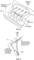
- the wearable device is an external cardiopulmonary physiologic monitor or cardioverter/defibrillator similar to those shown in WO 2017/035502 A1 having a first adhesive patient engagement substrate 2, a second adhesive patient engagement substrate 3, a plurality of housings 4 mounted on a housing base 5, a battery housing 6 containing a battery, a cable 7 extending between patient engagement substrates 2 and 3, mechanical connectors 8 for attaching the housing base 5 to the first patient engagement substrate 2, an electrical connector 1 for connecting the electrical components in housings 4 to the first patient engagement substrate and an electrical connector 9 for electrically connecting the battery housing 6 to the other housings 4.
- the housings 4 each contain one or more of a controller, a capacitor or other cardiopulmonary physiologic monitor or defibrillator electronics, and the housings 4 together with their base 5 form the reusable component of the wearable device 10.
- the first and second adhesive patient engagement substrates each have one or more electrodes on their bottom sides which, when the substrates 2 and 3 are connected to the housings 4, can sense cardiac activity or, in the case of a cardioverter/defibrillator, deliver a shock from the defibrillator components to a patient to whom the substrates are adhesively attached.
- the first and second patient engagement substrates and the battery in the battery housing are the disposable components of the wearable device.
- the wearable device can comprise override functionality for overriding a scheduled or already initiated device function or therapy.
- buttons 21 on the reusable component can be pressed simultaneously to initiate the override function.
- Other mechanisms for initiating the override are also possible (e.g., buttons located on opposing surfaces of the housings and configured to be squeezed or pinched simultaneously, buttons located on other surfaces of the wearable device such as the first or second patient engagement substrate, etc.).
- One aspect of the invention is the manner in which reusable component(s) of a wearable device may be mechanically connected to, and disconnected from, disposable component(s).
- Embodiments of the invention provide robust, intuitive, simple to operate (even for patients with low dexterity), load-bearing mechanical attachment between the reusable component of a wearable device (such as, e.g., an external cardiopulmonary physiologic monitor or cardioverter/defibrillator similar to those shown in WO 2017/035502 A1 ) and a disposable component of that device (such as, e.g., an adhesively attachable patient engagement substrate and/or a battery).
- the reusable component can be detached from the disposable component only when the wearable device is not being worn by the patient.
- the mechanical attachment mechanisms described herein can be used in combination with each other and with any of the embodiments described in this disclosure.
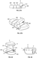
- FIGS 2A-E show an embodiment employing magnets as mechanical connectors.
- the wearable device 10 is an external cardiopulmonary physiologic monitor or cardioverter/defibrillator similar to those shown in WO 2017/035502 A1 .
- Components of the wearable device 10 include a first patient engagement substrate 2, a plurality of housings 4, and a second patient engagement substrate (not shown).
- the first patient engagement substrate 2 and the second patient engagement substrate each include an adhesive for attaching the substrate to the patient and one or more electrodes (not shown) for sensing cardiac activity or, in the case of a cardioverter/defibrillator, delivering an electrical shock to the patient.
- the housings 4 each contain one or more of a battery, a capacitor or a controller.
- housings 4 are movable with respect to each other and are in electrical communication with each other via, e.g., a flexible circuit (not shown).
- the electrical components within the housings are also in electrical communication with the electrodes in the first and second patient engagement substrates after the housings have been attached to the first patient engagement substrate, e.g., in a manner described further below.
- the reusable component of wearable device 10 includes housings 4, and the disposable component includes the first patient engagement substrate 2 and the second patient engagement substrate.
- magnets 8 are disposed on the top side 15 of patient engagement substrate 2 and on the bottom side 16 of housings 4 in corresponding positions that enable the housings to be mounted to the first patient engagement substrate as shown in Figure 1C .
- the magnets must be strong enough to support the weight of the housings and to withstand dislodging resulting from patient movement, snagging on clothing or other objects, etc., while still enabling intended detachment of the housings from the patient engagement substrate.
- the magnets are disposed closer to the top 17 of housings 4 so that the housings can serve as lever arms to facilitate separation of the patient engagement substrate's magnets from the housings' magnets.
- the magnets 8 shown in Figures 2D-E each have surface areas of 6.45cm 2 (1 square inch) and have a magnetic attachment strength of 90N (20 lbs).
- the housing 4 has a length of 6.35cm (2.5 inches).
- the removal force F R applied to the end of the moment arm of the housing 4 (as shown in Figure 2E ) to separate the magnets 8 is 17.8N (4 lbs.)-only 20% of the attachment force.
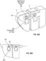
- Figures 3A-B show another embodiment of a mechanical connector 8 employing magnets in combination with a peg and keyhole connector for connecting and disconnecting a reusable component of a wearable device (such as an external cardiopulmonary physiologic monitor or cardioverter/defibrillator similar to those shown in WO 2017/035502 A1 ) to a disposable component of the wearable device.
- the mechanical connector of the disposable component 20 e.g., an adhesive patient engagement substrate
- the mechanical connector of the reusable component 28 (e.g., a cardiopulmonary physiologic monitor or defibrillator housing) has a peg 30 with an enlarged end 32 that can fit through the top 34 of access keyhole 26. After insertion of peg 30 into keyhole 26, peg 30 can be moved downward into the slotted portion 36 of keyhole 26 until a second magnet 38 on peg 30 meets and attaches to first magnet 22.
- Figures 4A-G show embodiments of mechanical connectors for connecting and disconnecting a reusable component 28 (such as cardiopulmonary physiologic monitor or defibrillator housings) of a wearable device (such as an external cardiopulmonary physiologic monitor or cardioverter/defibrillator similar to those shown in WO 2017/035502 A1 ) to a disposable component 20 (such as an adhesive patient engagement substrate) of the wearable device.
- the mechanical connectors are male and female mechanical elements.
- reusable component 28 has four housings 4.
- a male snap element 48 extends from each housing 46.
- the housings 4 may be connected by a flexible connector 50, such as a flexible circuit.
- an optional electrical connector 52 is also shown.
- Disposable component 20 has a plurality of female mechanical snap elements 54 in positions corresponding to the positions of male snap elements 48.
- Disposable component 20 also has an optional electrical connector 56.
- Figures 4C-E show one embodiment of mechanical snaps that may be used with the wearable device shown in Figures 4A-B .
- the female snap element 54 has a spring latch 58 that retains the head 60 of the male snap element inside of female snap element 54 until a sufficient force is applied to remove it, as suggested by Figure 4E.
- Figures 4F-G show another embodiment of a mechanical snap in which the female snap element 54 has a plurality of cantilever wall sections 62 separated by cutouts 64. Wall sections 62 move radially outward in response to an insertion force applied to the top 66 of the wall section by the head 60 of the male snap element during connection or a retraction force applied to the underside of a projection of the wall section by head 60 during disconnection.
- FIGS 5A-B show front and side views of an embodiment of a wearable device (such as an external cardiopulmonary physiologic monitor or cardioverter/defibrillator similar to those shown in WO 2017/035502 A1 ) in which the mechanical connectors 8 of the disposable component 20 (such as an adhesive patient engagement substrate) are disposed on pivotable bases 74 with pivot points 73 and attachment points 70.
- the reusable component 28 such as the cardiopulmonary physiologic monitor or defibrillator housings
- the reusable component can pivot away from the reusable component, thereby providing more movement flexibility while the wearable device is worn by the patient.
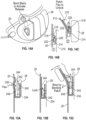
- Figures 6A-D show embodiments of mechanical connectors for connecting and disconnecting a reusable component 28 (such as cardiopulmonary physiologic monitor or defibrillator housings) of a wearable device (such as an external cardiopulmonary physiologic monitor or cardioverter/defibrillator similar to those shown in WO 2017/035502 A1 ) to a disposable component 20 (such as an adhesive patient engagement substrate) of the wearable device. Similar to the embodiment of Figures 3A-B , this embodiment employs a peg and keyhole connector. Housing 84 on the top side of disposable component 82 has an access keyhole 86.
- a reusable component 28 such as cardiopulmonary physiologic monitor or defibrillator housings
- a wearable device such as an external cardiopulmonary physiologic monitor or cardioverter/defibrillator similar to those shown in WO 2017/035502 A1
- a disposable component 20 such as an adhesive patient engagement substrate
- the mechanical connector of the reusable component 28 (e.g., a cardiopulmonary physiologic monitor or defibrillator housing) has a peg 90 with an enlarged end 92 that can fit through the top 94 of access keyhole 86. After insertion of peg 90 into keyhole 86, peg 90 can be moved downward into the slotted portion 96 of keyhole 86, and a lock 98 may be engaged to prevent peg 90 from moving back through slot 96, as shown in Figure 6A-C . There may be multiple mechanical connectors on the disposable component and on the reusable component. In some embodiments, the slotted portion of the keyhole may extend in two or more directions, as shown by the dogleg-shaped slot 96 of Figure 6D .
- Figures 7A-B show an embodiment of mechanical connectors for connecting and disconnecting a reusable component 28 (such as cardiopulmonary physiologic monitor or defibrillator housings) of a wearable device (such as an external cardiopulmonary physiologic monitor or cardioverter/defibrillator similar to those shown in WO 2017/035502 A1 ) to a disposable component 20 (such as an adhesive patient engagement substrate) of the wearable device.
- the disposable component mechanical connector is a cradle 104 having an inwardly projecting lip 106 at its open end.
- a ridge 108 or other outwardly projecting surface on the exterior of reusable component 100 engage lip 106 during insertion and deform cradle 104 sufficiently to snap the reusable component 100 into the cradle.
- This embodiment may provide a waterproof connection as a mechanical connection that is easier for users to see.
- the cradle may have an open end for sliding insertion of the reusable component into the cradle.
- Figures 8A-B show an embodiment of mechanical connectors for connecting and disconnecting a reusable component 28 (such as cardiopulmonary physiologic monitor or defibrillator housings) of a wearable device (such as an external cardiopulmonary physiologic monitor or cardioverter/defibrillator similar to those shown in WO 2017/035502 A1 ) to a disposable component 20 (such as an adhesive patient engagement substrate) of the wearable device.
- the disposable component mechanical connectors are adhesive areas 124 on the top side of the disposable component 20 that engage the bottom side of the reusable component 28.
- one end of the reusable component 28 may be pivoted away from the disposable component to expose pull tabs 126 associated with each adhesive area 124. Pulling down on pull tabs 126 separates the substrates beneath the adhesive areas from the disposable component, thereby allowing the removal of the reusable component from the disposable component.
- Figures 9A-C show an embodiment of mechanical connectors for connecting and disconnecting a reusable component 28 (such as cardiopulmonary physiologic monitor or defibrillator housings) of a wearable device (such as an external cardiopulmonary physiologic monitor or cardioverter/defibrillator similar to those shown in WO 2017/035502 A1 ) to a disposable component 20 (such as an adhesive patient engagement substrate) of the wearable device.
- a reusable component 28 such as cardiopulmonary physiologic monitor or defibrillator housings
- a wearable device such as an external cardiopulmonary physiologic monitor or cardioverter/defibrillator similar to those shown in WO 2017/035502 A1
- This embodiment employs hook and loop connectors 134 and 136 (such as Velcro ® material) on the top of the disposable component 132 and the bottom of the reusable component 130, respectively, to attach and detach the disposable component from the reusable component.
- Figures 10A-C show an embodiment of mechanical connectors for connecting and disconnecting a reusable component 28 (such as cardiopulmonary physiologic monitor or defibrillator housings) of a wearable device (such as an external cardiopulmonary physiologic monitor or cardioverter/defibrillator similar to those shown in WO 2017/035502 A1 ) to a disposable component 20 (such as an adhesive patient engagement substrate) of the wearable device.
- the reusable component mechanical connector has a post 144 with an elongated foot 146.
- the disposable component mechanical connector has a rotatable housing 148 with an opening 150 shaped just larger than the foot 146.
- a tab 152 extending from the housing 148 may be used to rotate housing 148 to change the orientation of opening 150 with respect to foot 146, thereby preventing post 144 from being withdrawn from housing 148.
- tab may be used to rotate housing 148 to line up opening 150 with foot 146, thereby permitting post 146 to be withdrawn from housing 148.
- Figures 11A-E show an embodiment of mechanical connectors for connecting and disconnecting a reusable component 28 (such as cardiopulmonary physiologic monitor or defibrillator housings) of a wearable device (such as an external cardiopulmonary physiologic monitor or cardioverter/defibrillator similar to those shown in WO 2017/035502 A1 ) to a disposable component 20 (such as an adhesive patient engagement substrate) of the wearable device.
- the disposable component mechanical connector is a buckle 164 attached at one end 166 to the top side of the disposable component.
- a prong 168 extends in a cantilever manner from the buckle's attached end 166, and a raised element 169 projects downwardly toward the top side of the disposable component.
- the reusable component mechanical connector has an opening 170 in a plate 172 disposed above the bottom side of the reusable component 160.
- the prong 168 is inserted between the plate 172 and the bottom side of the reusable component.
- the distance between the plate 172 and the bottom surface of the reusable component 162 is slightly greater than the distance between the bottom surface of raised element 169 and the top side of the disposable component, which cause prong 168 to bend upward as it is inserted between plate 172 and the bottom surface of the reusable component until the raised element 169 of the prong 168 goes into, and protrudes through, opening 170, thereby mechanically locking the reusable component to the disposable component.
- the disposable component may be bent to expose the portion of the raised element protruding through opening 170, as shown in Figure 11E , and the raised element may be pushed out of opening 170 to release the reusable component from the disposable component.
- the buckle of the disposable component mechanical connector may have one or more cantilevered elements extending laterally through one or more openings in the reusable component mechanical connector.
- the reusable component will have a plurality of housings, and in some embodiments there will be at least one mechanical connection between each housing and the disposable component. These mechanical connections could be spread evenly across the wearable device. Other embodiments will employ fewer mechanical connections. Furthermore, some mechanical connections may be stronger (e.g., to support the weight of the reusable portion) and some mechanical connections may be weaker (e.g., more for alignment and registration and less for supporting weight).
- Figure 12 shows a tool 180 for aligning the disposable component mechanical connectors 8 with the reusable component mechanical connectors 8.
- Tool 180 is a hinged container holding the disposable component 20 in proper alignment with the reusable component 28 so that when the lid 186 is closed, the mechanical connectors attach to each other.
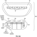
- FIGS 33A-B show a wearable device 500 (such as a cardiopulmonary physiologic monitor or an external cardioverter/defibrillator similar to those shown in WO 2017/035502 A1 ) with a reusable component 28 (such as cardiopulmonary physiologic monitor or defibrillator housings) and a disposable component 20 (such as an adhesive patient engagement substrate).
- the disposable component 20 has mechanical connectors 8 that connect to corresponding mechanical connectors 8 on the reusable component 28.
- Each mechanical connector 8 on the disposable component 20 has a conductive element 510 that contact one or more conductive elements 512 in each of the reusable component mechanical connectors 8 to close a circuit 512 leading to a microprocessor 514 in the reusable component.
- the microprocessor 514 detects that the circuit 512 is closed, it announces the successful mechanical connection between all of the mechanical connectors 8 with their corresponding mechanical connectors 8 by lighting one or more lights 416, vibrating a motor 412 and/or emitting a sound via a speaker 414.
- FIG. 13 shows a side view of an embodiment of the wearable device in which the disposable component includes an adhesive patient engagement substrate 20 and the reusable component includes a cardiopulmonary physiologic monitor or defibrillator housing 28.
- the patient engagement substrate 20 In order to access the mechanical connectors 8 with a tool 206, the patient engagement substrate 20 must be bent more than it could be bent while adhesively attached to the patient.
- Figures 14A-C show an embodiment of mechanical connectors for connecting and disconnecting a reusable component 28 (such as cardiopulmonary physiologic monitor or defibrillator housings) of a wearable device (such as an external cardiopulmonary physiologic monitor or cardioverter/defibrillator similar to those shown in WO 2017/035502 A1 ) to a disposable component (such as an adhesive patient engagement substrate 20) of the wearable device.
- the disposable component mechanical connector includes a slot 214 on the top side of the substrate 20 and a tab 216 extending from a bendable plate 218 on the substrate (or, alternatively, extending directly from the patient engagement substrate with no intervening plate).
- the reusable component mechanical connector has a peg 220 with an enlarged end 222 that can be moved into slot 214 from an open end 224 of the slot to connect the mechanical connectors.
- the tab 216 prevents the enlarged end 222 of peg 220 from leaving the slot 214, as shown in Figure 14B .
- tab 216 moves away from the enlarged end of the peg, enabling it to be removed from the slot 214, thereby disconnecting the cardiopulmonary physiologic monitor or defibrillator housing from the patient engagement substrate, as shown in Figure 14C .
- Figures 35A-B show an embodiment of mechanical connectors for connecting and disconnecting a reusable component (such as cardiopulmonary physiologic monitor or defibrillator housings) of a wearable device (such as an external cardiopulmonary physiologic monitor or cardioverter/defibrillator similar to those shown in WO 2017/035502 A1 ) to a disposable component (such as an adhesive patient engagement substrate) of the wearable device.
- the disposable component mechanical connector includes a plate 3504 comprising a bendable portion 3506 at one end of the plate, a protrusion 3508 in a mid section of the plate 3504, and a locking mechanism (e.g., spring lock, detent, etc.) at another portion of the plate 3510.
- the protrusion and lock may be positioned directly on the patient engagement substrate with no intervening plate.
- the protrusion 3508 is configured to interact with an aperture 3512 in a portion of the reusable component mechanical connector.
- the bendable portion 3506 of the disposable component mechanical connector is bent backwards, away from the reusable component mechanical connector.
- the reusable component mechanical connector can then be slid along a length of the disposable component mechanical connector, unlocking the locking mechanism.
- the disposable component mechanical connector can instead be slide along a length of the reusable component mechanical connector.
- Figure 35B shows another embodiment of a disposable component mechanical connector including a plate 3504 comprising a bendable portion 3506 at one end of the plate, a protrusion 3508 in a mid section of the plate 3504, and a spring lock 3512 at another portion of the plate.
- the protrusion 3508 Upon bending back the bendable portion 3506, the protrusion 3508 disengages from aperture 3512 in the reusable component mechanical connector.
- the plate 3510 can then be slid along a length of the disposable component mechanical connector, disengaging spring lock 3512.
- Figures 15A-C show an embodiment of mechanical connectors for connecting and disconnecting a reusable component 28 (such as cardiopulmonary physiologic monitor or defibrillator housings) of a wearable device (such as an external cardioverter/defibrillator similar to those shown in WO 2017/035502 A1 ) to a disposable component (such as an adhesive patient engagement substrate 20) of the wearable device.
- the disposable component mechanical connector includes a slot 234 on the top side of the substrate 20 and a tab 236 extending from a plate 248 on the substrate.
- the reusable component mechanical connector has a peg 240 with an enlarged end 242 that can be moved into slot 234 from an open end 244 of the slot to connect the mechanical connectors.
- Advancement of the enlarged portion of the peg into the slot causes the plate 248 to flex to move the tab 236 back, thereby permitting the enlarged end 242 of peg 240 to move into slot.
- the tab 236 prevents the enlarged end 242 of peg 240 from leaving the slot 234, as shown in Figure 15B .
- the substrate 20 and plate 248 are bent until the plate breaks, as shown in Figure 15C , thereby permitting tab 236 to move away from the enlarged end of the peg and enabling it to be removed from the slot 234, thereby disconnecting the cardiopulmonary physiologic monitor or defibrillator housing from the patient engagement substrate.
- perforations or seams in the patient engagement substrate may permit the user to tear the substrate to disconnect the reusable component from the substrate.
- Embodiments of the invention provide robust, waterproof, simple to operate (even for patients with low dexterity), reliable electrical connections between the reusable component of a wearable device (such as, e.g., an external cardiopulmonary physiologic monitor or cardioverter/defibrillator similar to those shown in WO 2017/035502 A1 ) and a disposable component of that device (such as, e.g., an adhesively attachable patient engagement substrate and/or a battery).
- the reusable component can be electrically disconnected from the disposable component only when the wearable device is not being worn by the patient.
- the electrical connection mechanisms described herein can be used in combination with each other and with any of the embodiments described in this disclosure.
- Figures 16A-B show an embodiment of electrical connectors for electrically connecting and disconnecting a reusable component 28 (such as electronic cardiopulmonary physiologic monitor or defibrillator components within housings 4) of a wearable device to a disposable component (such as first and second adhesive patient engagement substrates 2 and 3) of the wearable device.
- a first cable 258 extends from first patient engagement substrate 2 to the second patient engagement substrate 3
- a second cable 260 extends from a flexible circuit 261 in the first patient engagement substrate 2 to an electrical connector 262.
- Electrical connector 262 may be connected and disconnected from a mating electrical connector 253 in housing 4 of the reusable component 28.
- Cables 258 and 260 electrically connect the cardiopulmonary physiologic monitor or defibrillator components within housings 4 to electrodes 255 on the bottom side of patient engagement substrates 2 and 3, allowing for sensing of cardiac activity (such as, e.g., ECG signals) or, in the case of a defibrillator, delivery of electric shocks from electrodes 257 on the bottom sides of patient engagement substrates 2 and 3.
- a flexible circuit 50 provides electrical communication among the cardiopulmonary physiologic monitor or defibrillator components within housings 4.
- the electrical connector 262 may connect to a corresponding electrical connector 253 integrated into the flexible circuit 50.
- Figures 17A-B show an embodiment of electrical connectors for electrically connecting and disconnecting a reusable component 28 (such as electronic cardiopulmonary physiologic monitor or defibrillator components within housings 4) of a wearable device to a disposable component (such as first and second adhesive patient engagement substrates 2 and 3) of the wearable device.
- a first cable 258 extends from first patient engagement substrate 2 to the second patient engagement substrate 3
- a second cable 260 extends from one of the cardiopulmonary physiologic monitor or defibrillator housings 4 to an electrical connector 262.
- Electrical connector 262 may be connected and disconnected from a mating electrical connector 253 extending from a flexible circuit 261 in the first patient engagement substrate 2.
- Cables 258 and 260 electrically connect the cardiopulmonary physiologic monitor or defibrillator components within housings 4 to electrodes 255 on the bottom side of patient engagement substrates 2 and 3, allowing for sensing of cardiac activity (such as, e.g., ECG signals) or, in the case of a defibrillator, delivery of electric shocks from electrodes 257 on the bottom sides of patient engagement substrates 2 and 3.
- a flexible circuit 50 provides electrical communication among the cardiopulmonary physiologic monitor or defibrillator components within housings 4.
- the second cable 260 may extend from the flexible circuit 50 instead of from one of the housings 4.
- Figures 18A-B show an embodiment of electrical connectors for electrically connecting and disconnecting a reusable component 28 (such as electronic cardiopulmonary physiologic monitor or defibrillator components within housings 4) of a wearable device to a disposable component 20 (such as first and second adhesive patient engagement substrates 2 and 3) of the wearable device.
- a first cable 258 extends from first patient engagement substrate 2 to the second patient engagement substrate 3
- a second cable 310 extends from one of the cardiopulmonary physiologic monitor or defibrillator housings 4 to a first electrical connector 312
- a third cable 314 extends from a flexible circuit 261 of patient engagement substrate 2 to a second electrical connector 316 configured to electrically connect to, and disconnect from, the first electrical connector 312, as shown.
- Cables 258, 310 and 314 electrically connect the cardiopulmonary physiologic monitor or defibrillator components within housings 4 to electrodes 255 on the bottom side of patient engagement substrates 2 and 3, allowing for sensing of cardiac activity (such as, e.g., ECG signals) or, in the case of a defibrillator, delivery of electric shocks from electrodes 257 on the bottom sides of patient engagement substrates 2 and 3.
- a flexible circuit 50 provides electrical communication among the cardiopulmonary physiologic monitor or defibrillator components within housings 4.
- the second cable 300 may extend from the flexible circuit 50 instead of from one of the housings 4
- FIGs 19A-D show one embodiment of a combined electrical and mechanical connector.
- mounted on the top side of the wearable device's disposable component e.g., an adhesive patient engagement substrate 20
- An electrical connector 330 extends from a side of the housing 322 adjacent to the wide portion 326 of the keyhole opening 324.
- the corresponding structure on the reusable component of the wearable device is a peg 334 having an enlarged end 336 to form the mechanical connector of the reusable component.
- the reusable component's electrical connector 338 is shown adjacent to peg 334.
- the enlarged end 336 of peg 334 is inserted into the wide portion 326 of keyhole opening 324, as shown in Figure 19C .
- the peg 334 is then advanced in keyhole opening 324 until the enlarged end 336 is beneath the narrow portion 328 of the keyhole opening such that the peg can no longer be withdrawn from housing 322, thereby mechanically connecting the reusable component to the disposable component.
- the reusable component's electrical connector 338 will engage the disposable component's electrical connector 330 to electrically connect the reusable component to the disposable component.
- a movable disconnection actuator 340 may be depressed to move peg 334 to the wide portion 326 of keyhole opening 324 to disconnect the electrical connectors 330 and 338 and to permit the enlarged end 336 of the peg to be removed from the keyhole opening 324.
- Figure 20 shows an embodiment of a wearable device's disposable component (such as, e.g., an adhesive patient engagement substrate 20) with four mechanical connectors 8 (such as, e.g., the snap connectors described above) and an electrical connector 1.
- a wearable device's disposable component such as, e.g., an adhesive patient engagement substrate 20
- four mechanical connectors 8 such as, e.g., the snap connectors described above
- an electrical connector 1 such as, e.g., the snap connectors described above
- the wearable device's reusable component e.g., housings containing cardiopulmonary physiologic monitor or cardioverter/defibrillator similar to those shown in WO 2017/035502 A1 components
- the reusable component's electrical connector will automatically connect to electrical connector 1 at the same time.
- Figure 21 shows a partial view of an embodiment of a wearable device (such as a cardiopulmonary physiologic monitor or cardioverter/defibrillator similar to those shown in WO 2017/035502 A1 ) having a reusable component (e.g., housings 4 containing cardiopulmonary physiologic monitor or defibrillator components) mechanically attached in a detachable manner to an adhesive flexible engagement substrate 362 of the device's disposable component.
- Other parts of the disposable component include cable 364 and battery housing 6 containing one or more batteries.
- Battery housing 6 has an electrical connector 368 and a mechanical connector 370 which may be connected and disconnected to an electrical connector 9 and a mechanical connector 374, respectively, on the housings 4.
- connectors 9 and 368 and cable 364 electrically connect the cardiopulmonary physiologic monitor or defibrillator components within housings 4 to electrodes on the bottom side of patient engagement substrate 362 and a second patient engagement substrate (not shown), allowing for sensing of cardiac activity (such as, e.g., ECG signals) or, in the case of a defibrillator, delivery of electric shocks from electrodes on the bottom sides of the patient engagement substrates.
- a flexible circuit (not shown) provides electrical communication among the cardiopulmonary physiologic monitor or defibrillator components within housings 4.
- the electrical connectors may be, e.g., edge card connectors (i.e., USB), spring probe connectors, Zero Insertion Force (ZIF) connectors, pin-probe insertion connectors, twist and lock connectors, etc. Sealing O-rings may be used to waterproof the electrical connection.
- edge card connectors i.e., USB
- spring probe connectors i.e., spring probe connectors
- ZIF Zero Insertion Force
- pin-probe insertion connectors pin-probe insertion connectors
- twist and lock connectors etc.
- Sealing O-rings may be used to waterproof the electrical connection.
- FIGS 22A-B show another embodiment of mechanical and electrical connectors between disposable and reusable components of a wearable device, such as a cardiopulmonary physiologic monitor or cardioverter/defibrillator similar to those shown in WO 2017/035502 A1 .
- Reusable component 28 e.g., a housing containing cardiopulmonary physiologic monitor or defibrillator components
- An electrical connector receptacle (not shown) is also disposed in the housing recess.
- FIG 22A an electrical connector 262 at the end of a cable 260 extending from a disposable component (e.g., an adhesive flexible engagement substrate, not shown) of the wearable device has been mated with the reusable component's electrical connector prior to mechanical connection between the reusable and disposable components.
- Figure 22B is a view of the bottom side of the reusable component 28 and the mechanical connector 8 of the disposable component.
- Mechanical connector 8 has a keyhole opening 294 with a wide portion 296 (permitting insertion of the enlarged end 284 of peg 282) and a narrow portion 298 into which peg 282 can be slid to form the mechanical connection between the components.
- peg 282 is disposed in the narrow portion 298 of opening 294, a surface 300 of mechanical connector 8 engages electrical connector 262, preventing it from being disconnected from the reusable component's electrical connector.
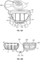
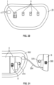
- FIGS 23A-B show the bottom side of an embodiment of a reusable portion of a wearable device (such as a cardiopulmonary physiologic monitor or cardioverter/defibrillator similar to those shown in WO 2017/035502 A1 ) with four housings 4.
- a flexible circuit 50 having multiple electrical conductors (not shown) and at least one electrical connector 314 (shown in phantom in Figure 23B ) extending from the conductors in the flexible circuit to the electrical components in each of the housings 4.
- An overmold material (such as hot melt polyamide, polyolefin, or rubber-based thermoplastic setting adhesives) provides a robust mechanical connection between the housings while permitting flexing and other relative movement between the housings.
- the overmold material also has dielectric and waterproof properties enhancing the safety of the wearable device even during showering or other activities.
- Figure 24 shows a cut-away side view of another embodiment of a reusable component of a wearable device (such as a cardiopulmonary physiologic monitor or a cardioverter/defibrillator similar to those shown in WO 2017/035502 A1 ).
- a flexible circuit 50 extends through and between housings4. Flexible circuit 50 has multiple electrical conductors providing communication among the electrical components within the housings 4.
- Mechanical connectors 8 extend from the bottom sides 16 of housings 4 to provide mechanical attachment to, and detachment from, a disposable component of the wearable device, such as an adhesive patient engagement substrate (not shown).
- flexible circuit 50 provides a robust mechanical connection between the housings while permitting flexing and other relative movement between the housings.
- Figure 36 shows an embodiment of electrical connections between a flexible circuit (such as the flexible circuits described above, extending through and between housings of the wearable device's reusable component.
- the electrical connections between the flex circuit 50 and the PCBAs 3602 in the housing 4 comprise screws 3606 inserted through the flex circuit 50 into threaded standoffs 3608 that are soldered to the PCBAs 3602.
- Conductive material 3610 e.g., copper
- the screw 3606 is passed through the hole 3612 and threads into the standoff 3608, it compresses the flex circuit against the standoff, thereby making reliable electrical contact between the flex circuit 50 and the PCBAs 3602.
- the PCBAs can also comprise a low voltage connector (e.g., a fine-pitch multi-conductor connector) that is simultaneously engaged upon compression of the flex circuit against the standoff, enabling low-voltage communication lines.
- a low voltage connector e.g., a fine-pitch multi-conductor connector
- the disposable component is a patient engagement substrate adhesively attached to a patient and the reusable component is a plurality of housings mechanically attached to the patient engagement substrate. As the patient moves, the shape of the patient engagement substrate may change.
- Embodiments of the invention provide mechanical connection features between the reusable and disposable components accommodating changes in shape of one of the components.
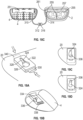
- Figures 25A-B show a wearable device (such as a cardiopulmonary physiologic monitor or a cardioverter/defibrillator similar to those shown in WO 2017/035502 A1 ) having a reusable component with a plurality of housings 4 connected by a flexible connection (such as a flexible circuit, as described above) and a disposable component 20 (such as an adhesive patient engagement substrate).
- the mechanical connectors of the reusable component include pegs 336 having enlarged ends 338.
- the mechanical connectors of the disposable component include slots 340, 342, 344 and 346 in positions corresponding to pegs 326. Slots 340, 344 and 346 are much wider than the width of enlarged end 338, permitting movement of enlarged end 338 within slots 340, 344 and 346 as patient engagement substrate 20 bends and straightens with the patient's movement.
- Anchor slot 342 on the other hand, has a width only slightly larger than enlarged end 338, so that its corresponding peg moves only slightly or not at all as the other pegs move within their slots. This arrangement permits some relative movement between the reusable and disposable components of the wearable device without causing complete mechanical disconnection of the components.
- FIGS 26A-B show partial views of the reusable component of a wearable device (such as a cardiopulmonary physiologic monitor or a cardioverter/defibrillator similar to those shown in WO 2017/035502 A1 ) having a plurality of housings 4 (each containing, e.g., one or more of a controller, a capacitor or a battery) mechanically and electrically connected by a flexible circuit 50 having electrical connections 354 extending into the housings 4.
- Housings 4 each containing, e.g., one or more of a controller, a capacitor or a battery
- Mechanical connectors project from the back sides of housings 4 from positions above the flexible circuit 50. This arrangement of mechanical connectors and flexible circuit reduces the overall height of the reusable component.
- the disposable component of the wearable device includes a replaceable battery.
- the battery housing is part of the disposable component that may be electrically and mechanically connected to, and disconnected from, the reusable component of the wearable device.
- FIGS 27A-B show an embodiment of a reusable component of a wearable device (such as a cardiopulmonary physiologic monitor or a cardioverter/defibrillator similar to those shown in WO 2017/035502 A1 ) having a plurality of housings 360, 362, 364 and 366 mechanically and electrically connected by a flexible circuit.
- the disposable component of the wearable device includes a battery housing 6.
- a reusable component mechanical connector 8 extends from a surface of housing 366; battery housing 6 has a corresponding mechanical connector 374.
- Battery housing also has an electrical connector 9, and housing 366 has a corresponding electrical connector (not shown). The electrical and mechanical connections between battery housing 6 and reusable component housing 366 occur simultaneously.
- FIG 28 shows a partial view of another embodiment of a reusable component of a wearable device (such as a cardiopulmonary physiologic monitor or a cardioverter/defibrillator similar to those shown in WO 2017/035502 A1 ) having a plurality of housings 380 and 382 mechanically and electrically connected by a flexible circuit (not shown).
- the disposable component of the wearable device includes a battery housing 6.
- Reusable component mechanical connectors 8 are disposed in housing 382 (only one is shown in Figure 28 ); battery housing 6 has corresponding mechanical connectors 374.
- Battery housing also has an electrical connector 9, and housing 382 has a corresponding electrical connector 9. The electrical and mechanical connections between battery housing 6 and reusable component housing 382 occur simultaneously.
- Figure 37 shows an embodiment of a reusable component of a wearable device (such as a cardiopulmonary physiologic monitor or a cardioverter/defibrillator similar to those shown in WO 2017/035502 A1 ) having a plurality of housings 4 mechanically and electrically connected by a flexible circuit (not shown).
- the disposable component 20 of the wearable device is mechanically connected to a disposable battery 3708.
- the connection between the disposable component and the battery can be permanent, such that the battery is disposed of along with the disposable component.
- the reusable component modules can be configured to be lowered onto the disposable component and battery such that they make an electrical connection, and a mechanical connection to hold onto the battery module. The reusable component can be lifted off of the battery and disposable component prior to disposal of the disposable component.
- Figure 29 shows aspects of a disposable component of a wearable device (such as a cardiopulmonary physiologic monitor or a cardioverter/defibrillator similar to those shown in WO 2017/035502 A1 ).
- the disposable component includes an adhesive patient engagement substrate 2, a cable 7 connecting to a second patient engagement substrate (not shown), a battery housing 6 containing one or more batteries, and a plurality of mechanical connectors 8 for connecting to corresponding mechanical connectors on a reusable component of the wearable device.
- the battery housing also has an electrical connector (not shown) configured to mate with a corresponding electrical connector in the reusable component for providing electrical communication between the electrical components in the reusable component and the battery and other electrical components of the disposable component, such as an electrode disposed on the bottom side of the patient engagement substrate.
- Figures 30A-B show an embodiment of a wearable device (such as a cardiopulmonary physiologic monitor or a cardioverter/defibrillator similar to those shown in WO 2017/035502 A1 ) in which the disposable component includes an adhesive patient engagement substrate 20 and a cable 260, and the reusable component includes a plurality of housings 4 each containing one or more of a controller 404, a battery 406 or a capacitor.
- An electrical connector 262 on cable 260 connects to a corresponding electrical connector 253 on one of the housings 4.
- connection of electrical connectors 262 and 253 closes a circuit to provide an alert via a vibration motor 412, a speaker 414 and/or a light 416 to show that the electrical connection has been made.
- the battery is a rechargeable battery and is part of the reusable component.
- the reusable component has a plurality of housings 420, 422, 424 and 426.
- the rechargeable battery is disposed in housing 426, and it can be charged by inserting a charger connector 430 connected to a charger (not shown) into a port 432 in housing 426.
- the rechargeable battery in the reusable component 28 may be charged wirelessly via a charging pad 442 while the patient 444 is wearing the wearable device.
- Figures 34A-D show yet another embodiment of mechanical connectors for connecting and disconnecting a reusable component 28(such as cardiopulmonary physiologic monitor or defibrillator housings ) of a wearable device (such as an external cardioverter/defibrillator similar to those shown in WO 2017/035502 A1 ) to a disposable component (such as an adhesive patient engagement substrate 603) of the wearable device.
- the disposable component mechanical connector has a latch 608 supported by a latch support 606 extending from a base 604.
- a spring 610 biases the latch 608 in the downward position shown in Figure 34B .
- the corresponding reusable component mechanical connector 8 is shown apart from the reusable component in Figures 34B-D .
- Reusable component mechanical connector 8 has an opening leading to a cavity sized and configured to receive the latch 608 and latch support 606.
- reusable component mechanical connector 8 is moved in the direction of arrow 616 in Figure 34B , its opening will make sliding contact with the lower face of latch 608, moving latch 608 upward against the action of spring 610 until the two mechanical connectors are in their mating position, shown in Figures 34C-D .
- spring 610 moves latch 608 downward to engage an inner surface of reusable component mechanical connector 8 to hold the two components together.
- a removal trigger 612 can be actuated to compress spring 610 and move latch 608 upwards into latch support 606.
- connection between the reusable component mechanical connector 8 and the disposable component connectors is that they allow motion in the direction indicated by arrows 630 shown in Figure 34D , but constrain motion in the direction indicated by arrows 632 in Figure 34C .
- This capability may be allowed by a similar concept as that described with respect to Figures 25A and 25B .
- the width of the opening in the reusable component mechanical connector can be greater than the width of the latch support, allowing sliding movement along the direction indicated by arrows 630 up to an amount equal to the difference in width between the opening in the reusable component and the widest portion of the latch support 606 positioned within the opening.
- This connection allows the reusable component to be held securely against the disposable component, but also allows the reusable component housings to slide back and forth during flexing caused by user movement. This capability can be very important for wear comfort and longevity of the device.
- the reusable component 28 has four housings 4. Three of the housings have the mechanical connector 8 described with respect to Figures 34B-D .
- a fourth housing has an integrated mechanical/electrical connector 620 that mates with a corresponding mechanical/electrical connector 622 in the disposable component.
- a flexible circuit 50 provides electrical communication among housings 4.
- references to a structure or feature that is disposed "adjacent" another feature may have portions that overlap or underlie the adjacent feature.
- the device may be otherwise oriented (rotated 90 degrees or at other orientations) and the spatially relative descriptors used herein interpreted accordingly.
- the terms “upwardly”, “downwardly”, “vertical”, “horizontal” and the like are used herein for the purpose of explanation only unless specifically indicated otherwise.
- first and second may be used herein to describe various features/elements (including steps), these features/elements should not be limited by these terms, unless the context indicates otherwise. These terms may be used to distinguish one feature/element from another feature/element. Thus, a first feature/element discussed below could be termed a second feature/element, and similarly, a second feature/element discussed below could be termed a first feature/element without departing from the teachings of the present invention.
- a numeric value may have a value that is +/- 0.1% of the stated value (or range of values), +/- 1% of the stated value (or range of values), +/- 2% of the stated value (or range of values), +/- 5% of the stated value (or range of values), +/-10% of the stated value (or range of values), etc.
- Any numerical values given herein should also be understood to include about or approximately that value, unless the context indicates otherwise. For example, if the value "10" is disclosed, then “about 10" is also disclosed. Any numerical range recited herein is intended to include all sub-ranges subsumed therein.
Landscapes
- Health & Medical Sciences (AREA)
- Life Sciences & Earth Sciences (AREA)
- Animal Behavior & Ethology (AREA)
- Veterinary Medicine (AREA)
- Public Health (AREA)
- Engineering & Computer Science (AREA)
- Biomedical Technology (AREA)
- General Health & Medical Sciences (AREA)
- Cardiology (AREA)
- Heart & Thoracic Surgery (AREA)
- Pathology (AREA)
- Surgery (AREA)
- Molecular Biology (AREA)
- Medical Informatics (AREA)
- Biophysics (AREA)
- Physics & Mathematics (AREA)
- Nuclear Medicine, Radiotherapy & Molecular Imaging (AREA)
- Radiology & Medical Imaging (AREA)
- Electrotherapy Devices (AREA)
- Battery Mounting, Suspending (AREA)
- Measurement And Recording Of Electrical Phenomena And Electrical Characteristics Of The Living Body (AREA)
Description
- The present disclosure relates generally to wearable devices, such as external cardiopulmonary physiologic monitors or defibrillators. In particular, the disclosure relates to automatic external cardiopulmonary physiologic monitors or defibrillators that can be continuously and comfortably worn by a patient for an extended period of time.
-
WO 2017/035502 A1 discloses multiple embodiments of an external defibrillator that is adhesively attached to the patient and that can be comfortably worn around the clock during showering, sleeping and normal activities. The adhesive patches and batteries of these devices may have useful lives that are shorter than the other components of the defibrillator. In addition, the patient may need to wear the defibrillator beyond the ends of the useful lives of the adhesive patches and/or batteries. -
US 2009/306730 A1 discloses a defibrillator for permanent external application to a patient, with a protective shell arrangement receiving a base unit with defibrillator components, an electrode arrangement connected or connectable to the shell arrangement, and a support device. An ergonomic adaptation to the person wearing the defibrillator is achieved by the defibrillator components being spatially combined into subsidiary modules, and the shell arrangement has several subsidiary shells to which the subsidiary modules are distributed and which are movable relative to one another and connected to one another mechanically and electrically. - The invention is defined in
claim 1. Further aspects and preferred embodiment of the invention are defined in the dependent claims. Any aspects, embodiments and examples of the present disclosure which do not fall under the scope of the appended claims are provided for illustrative purposes. - The novel features of the invention are set forth with particularity in the claims that follow. A better understanding of the features and advantages of the present invention will be obtained by reference to the following detailed description that sets forth illustrative embodiments of the disclosure, and the accompanying drawings of which:
-
Figures 1A-D show a wearable device having reusable and disposable components. -
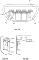
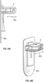
Figures 2A-E show an embodiment of a wearable device employing magnets as mechanical connectors. -
Figures 3A-B show another embodiment of a mechanical connector employing magnets in combination with a peg and keyhole connector for connecting and disconnecting a reusable component of a wearable device. -
Figures 4A-G show embodiments of mechanical connectors for connecting and disconnecting a reusable component of a wearable device to a disposable component of the wearable device. -
Figures 5A-B show an embodiment of a wearable device in which the mechanical connectors of the disposable component are disposed on pivotable bases. -
Figures 6A-D show embodiments of mechanical connectors for connecting and disconnecting a reusable component of a wearable device to a disposable component of the wearable device. -
Figures 7A-B show embodiments of mechanical connectors for connecting and disconnecting a reusable component of a wearable device to a disposable component of the wearable device. -
Figures 8A-B show embodiments of mechanical connectors for connecting and disconnecting a reusable component of a wearable device to a disposable component of the wearable device. -
Figures 9A-C show embodiments of mechanical connectors for connecting and disconnecting a reusable component of a wearable device to a disposable component of the wearable device. -
Figures 10A-C show embodiments of mechanical connectors for connecting and disconnecting a reusable component of a wearable device to a disposable component of the wearable device. -
Figures 11A-E show embodiments of mechanical connectors for connecting and disconnecting a reusable component of a wearable device to a disposable component of the wearable device. -
Figure 12 shows a tool for aligning the disposable component mechanical connectors with the reusable component mechanical connectors. -
Figure 13 shows an embodiment of a wearable device in which the disposable component includes an adhesive patient engagement substrate and the reusable component includes a cardiopulmonary physiologic monitor or defibrillator housing. -
Figures 14A-C show embodiments of mechanical connectors for connecting and disconnecting a reusable component of a wearable device to a disposable component of the wearable device. -
Figures 15A-C show embodiments of mechanical connectors for connecting and disconnecting a reusable component of a wearable device to a disposable component of the wearable device. -
Figures 16A-C show an embodiment of electrical connectors for electrically connecting and disconnecting a reusable component of a wearable device to a disposable component of the wearable device. -
Figures 17A-C show an embodiment of electrical connectors for electrically connecting and disconnecting a reusable component of a wearable device to a disposable component of the wearable device. -
Figures 18A-C show embodiments of electrical connectors for electrically connecting and disconnecting a reusable component of a wearable device to a disposable component of the wearable device. -
Figures 19A-D show an embodiment of a combined electrical and mechanical connector. -
Figure 20 shows an embodiment of a wearable device's disposable component with four mechanical connectors and an electrical connector. -
Figure 21 shows a partial view of an embodiment of a wearable device having a reusable component mechanically attached in a detachable manner to an adhesive flexible engagement substrate of the device's disposable component. -
Figures 22A-B show another embodiment of mechanical and electrical connectors between disposable and reusable components of a wearable device. -
Figure 23A-B show the bottom side of an embodiment of a reusable portion of a wearable device with four housings. -
Figure 24 shows a cut-away side view of another embodiment of a reusable component of a wearable device. -
Figures 25A-B show a wearable device having a reusable component with a plurality of housings connected by a flexible connection. The mechanical connection shown in these figures permits some relative movement between the reusable and disposable components of the wearable device without causing complete mechanical disconnection of the components. -
Figures 26A-B show partial views of the reusable component of a wearable device having a plurality of housings mechanically and electrically connected by a flexible circuit having electrical connections extending into the housings. -
Figures 27A-B show an embodiment of a reusable component of a wearable device having a plurality of housings mechanically and electrically connected by a flexible circuit. -
Figure 28 shows a partial view of another embodiment of a reusable component of a wearable device having a plurality of housings mechanically and electrically connected by a flexible circuit. -
Figure 29 shows aspects of a disposable component of a wearable device (such as a cardiopulmonary physiologic monitor or a cardioverter/defibrillator. -
Figure 30A-B show an embodiment of a wearable device in which the disposable component includes an adhesive patient engagement substrate and a cable, and the reusable component includes a plurality of housings each containing one or more of a controller, a battery or a capacitor. -
Figures 31A-B show an embodiment of a wearable device having a rechargeable battery in which the reusable component has a plurality of housings. -
Figures 32A-B show an embodiment of a wearable device having a rechargeable battery in which the battery may be charged wirelessly via a charging pad while the patient is wearing the wearable device. -
Figures 33A-B show a wearable device with a reusable component and a disposable component. -
Figures 34A-D show yet another embodiment of mechanical connectors for connecting and disconnecting a reusable component of a wearable device to a disposable component of the wearable device. -
Figures 35A-B show an embodiment of a trigger prevention mechanism for preventing disconnection of a reusable component of a wearable device from a disposable component of the wearable device while the device is being worn. -
Figure 36 shows an embodiment of an electrical connection between a flexible circuit and PCBAs in a reusable component of a wearable device. -
Figure 37 shows an embodiment of interaction between a reusable component of a wearable device and a disposable component and attached battery of the wearable device. - Embodiments of the invention provide an adhesively mounted wearable device, such as an external cardiopulmonary physiologic monitor or cardioverter/defibrillator similar to those shown in
WO 2017/035502 A1 , whose adhesive patient engagement substrate(s) and battery can be mechanically and electrically attached and detached from the device's reusable electronics. In particular, the devices of this invention enable a user, particularly a patient with low dexterity, poor hand/arm strength, poor vision, etc., to perform the following steps prior to wearing the device: (1) mechanically attach reusable electronics to adhesive patient engagement substrate(s); (2) electrically connect reusable electronics to adhesive patient engagement substrate(s); (3) mechanically attach a battery to the reusable electronics; and (4) electrically connect the battery to the reusable electronics. These embodiments provide waterproof electrical connections, enabling the patient to shower and perform other activities while wearing the device. The mechanical and electrical connections of these various embodiments can also withstand expected mechanical forces without detaching or disconnecting, such as when the patient moves or changes position (e.g., sits up, lies down, falls, walks), when the device engages another object (e.g., engaging a seatbelt or clothing covering the device). Embodiments of the invention provide mechanical and electrical connections between disposable and reusable components that are difficult or impossible to disconnect while the device is being worn by the patient. - The reusable component of the wearable device of this invention have multiple housings or modules each containing one or more electrical components. For example, in embodiments in which the wearable device is a cardioverter/defibrillator similar to those shown in
WO 2017/035502 A1 , the housings or modules may each contain one or more of a controller and a capacitor. A flexible electrical circuit extends between the housings or modules to provide connections among the electronic components. The flexible electrical circuit may be waterproof or covered with waterproof material. In addition, in embodiments of the invention the flexible circuit can withstand the flexing twisting, stretching, bending, compression, tension, etc., that may come from patient movement while wearing the wearable device. In some embodiments, the flexible electrical circuit is exterior to the housings or modules, and waterproof electrical connections extend from the flexible electrical circuit to the electrical components in the housings or modules. In other embodiments, the flexible electrical circuit is at least partially inside one or more of the housings or modules. - An illustrative example of a wearable device having reusable and disposable components is shown in
Figures 1A-D . In this example, the wearable device is an external cardiopulmonary physiologic monitor or cardioverter/defibrillator similar to those shown inWO 2017/035502 A1 having a first adhesivepatient engagement substrate 2, a second adhesive patient engagement substrate 3, a plurality ofhousings 4 mounted on ahousing base 5, abattery housing 6 containing a battery, acable 7 extending betweenpatient engagement substrates 2 and 3,mechanical connectors 8 for attaching thehousing base 5 to the firstpatient engagement substrate 2, anelectrical connector 1 for connecting the electrical components inhousings 4 to the first patient engagement substrate and anelectrical connector 9 for electrically connecting thebattery housing 6 to theother housings 4. Thehousings 4 each contain one or more of a controller, a capacitor or other cardiopulmonary physiologic monitor or defibrillator electronics, and thehousings 4 together with theirbase 5 form the reusable component of thewearable device 10. The first and second adhesive patient engagement substrates each have one or more electrodes on their bottom sides which, when thesubstrates 2 and 3 are connected to thehousings 4, can sense cardiac activity or, in the case of a cardioverter/defibrillator, deliver a shock from the defibrillator components to a patient to whom the substrates are adhesively attached. The first and second patient engagement substrates and the battery in the battery housing are the disposable components of the wearable device. The wearable device can comprise override functionality for overriding a scheduled or already initiated device function or therapy. For example, in the case of a cardioverter/defibrillator, the device can be controlled to cancel a scheduled shock. In some embodiments, the same buttons can also be used to interact with various user interface prompts, as needed (e.g., turn on, perform status check, etc.). Controls orbuttons 21 on the reusable component can be pressed simultaneously to initiate the override function. Other mechanisms for initiating the override are also possible (e.g., buttons located on opposing surfaces of the housings and configured to be squeezed or pinched simultaneously, buttons located on other surfaces of the wearable device such as the first or second patient engagement substrate, etc.). - Various mechanical connectors, electrical connectors and device configurations are described below. Each can be used in combination with others.
- One aspect of the invention is the manner in which reusable component(s) of a wearable device may be mechanically connected to, and disconnected from, disposable component(s). Embodiments of the invention provide robust, intuitive, simple to operate (even for patients with low dexterity), load-bearing mechanical attachment between the reusable component of a wearable device (such as, e.g., an external cardiopulmonary physiologic monitor or cardioverter/defibrillator similar to those shown in
WO 2017/035502 A1 ) and a disposable component of that device (such as, e.g., an adhesively attachable patient engagement substrate and/or a battery). In many of the embodiments, the reusable component can be detached from the disposable component only when the wearable device is not being worn by the patient. The mechanical attachment mechanisms described herein can be used in combination with each other and with any of the embodiments described in this disclosure. -
Figures 2A-E show an embodiment employing magnets as mechanical connectors. In the illustrated embodiment, thewearable device 10 is an external cardiopulmonary physiologic monitor or cardioverter/defibrillator similar to those shown inWO 2017/035502 A1 . Components of thewearable device 10 include a firstpatient engagement substrate 2, a plurality ofhousings 4, and a second patient engagement substrate (not shown). The firstpatient engagement substrate 2 and the second patient engagement substrate each include an adhesive for attaching the substrate to the patient and one or more electrodes (not shown) for sensing cardiac activity or, in the case of a cardioverter/defibrillator, delivering an electrical shock to the patient. Thehousings 4 each contain one or more of a battery, a capacitor or a controller. In this embodiment,housings 4 are movable with respect to each other and are in electrical communication with each other via, e.g., a flexible circuit (not shown). The electrical components within the housings are also in electrical communication with the electrodes in the first and second patient engagement substrates after the housings have been attached to the first patient engagement substrate, e.g., in a manner described further below. The reusable component ofwearable device 10 includeshousings 4, and the disposable component includes the firstpatient engagement substrate 2 and the second patient engagement substrate. - As shown in
Figures 2A-E ,magnets 8 are disposed on thetop side 15 ofpatient engagement substrate 2 and on thebottom side 16 ofhousings 4 in corresponding positions that enable the housings to be mounted to the first patient engagement substrate as shown inFigure 1C . The magnets must be strong enough to support the weight of the housings and to withstand dislodging resulting from patient movement, snagging on clothing or other objects, etc., while still enabling intended detachment of the housings from the patient engagement substrate. In this embodiment, the magnets are disposed closer to the top 17 ofhousings 4 so that the housings can serve as lever arms to facilitate separation of the patient engagement substrate's magnets from the housings' magnets. As an example, themagnets 8 shown inFigures 2D-E each have surface areas of 6.45cm2 (1 square inch) and have a magnetic attachment strength of 90N (20 lbs). Thehousing 4 has a length of 6.35cm (2.5 inches). The removal force FR applied to the end of the moment arm of the housing 4 (as shown inFigure 2E ) to separate themagnets 8 is 17.8N (4 lbs.)-only 20% of the attachment force. -
Figures 3A-B show another embodiment of amechanical connector 8 employing magnets in combination with a peg and keyhole connector for connecting and disconnecting a reusable component of a wearable device (such as an external cardiopulmonary physiologic monitor or cardioverter/defibrillator similar to those shown inWO 2017/035502 A1 ) to a disposable component of the wearable device. In this embodiment, the mechanical connector of the disposable component 20 (e.g., an adhesive patient engagement substrate) has afirst magnet 22 disposed within ahousing 24 having anaccess keyhole 26. The mechanical connector of the reusable component 28 (e.g., a cardiopulmonary physiologic monitor or defibrillator housing) has a peg 30 with anenlarged end 32 that can fit through the top 34 ofaccess keyhole 26. After insertion of peg 30 intokeyhole 26, peg 30 can be moved downward into the slottedportion 36 ofkeyhole 26 until asecond magnet 38 on peg 30 meets and attaches tofirst magnet 22. There may be multiple mechanical connectors on the disposable component and on the reusable component. -
Figures 4A-G show embodiments of mechanical connectors for connecting and disconnecting a reusable component 28 (such as cardiopulmonary physiologic monitor or defibrillator housings) of a wearable device (such as an external cardiopulmonary physiologic monitor or cardioverter/defibrillator similar to those shown inWO 2017/035502 A1 ) to a disposable component 20 (such as an adhesive patient engagement substrate) of the wearable device. In this embodiment, the mechanical connectors are male and female mechanical elements. As shown inFigure 4A ,reusable component 28 has fourhousings 4. Amale snap element 48 extends from eachhousing 46. As shown, thehousings 4 may be connected by aflexible connector 50, such as a flexible circuit. Also shown is an optionalelectrical connector 52.Disposable component 20 has a plurality of femalemechanical snap elements 54 in positions corresponding to the positions ofmale snap elements 48.Disposable component 20 also has an optionalelectrical connector 56. -
Figures 4C-E show one embodiment of mechanical snaps that may be used with the wearable device shown inFigures 4A-B . In this embodiment, thefemale snap element 54 has aspring latch 58 that retains thehead 60 of the male snap element inside offemale snap element 54 until a sufficient force is applied to remove it, as suggested byFigure 4E. Figures 4F-G show another embodiment of a mechanical snap in which thefemale snap element 54 has a plurality ofcantilever wall sections 62 separated bycutouts 64.Wall sections 62 move radially outward in response to an insertion force applied to the top 66 of the wall section by thehead 60 of the male snap element during connection or a retraction force applied to the underside of a projection of the wall section byhead 60 during disconnection. -
Figures 5A-B show front and side views of an embodiment of a wearable device (such as an external cardiopulmonary physiologic monitor or cardioverter/defibrillator similar to those shown inWO 2017/035502 A1 ) in which themechanical connectors 8 of the disposable component 20 (such as an adhesive patient engagement substrate) are disposed onpivotable bases 74 withpivot points 73 and attachment points 70. When the reusable component 28 (such as the cardiopulmonary physiologic monitor or defibrillator housings) are mechanically attached to thedisposable component 20 using any of the mechanical connectors disclosed herein, the reusable component can pivot away from the reusable component, thereby providing more movement flexibility while the wearable device is worn by the patient. -
Figures 6A-D show embodiments of mechanical connectors for connecting and disconnecting a reusable component 28 (such as cardiopulmonary physiologic monitor or defibrillator housings) of a wearable device (such as an external cardiopulmonary physiologic monitor or cardioverter/defibrillator similar to those shown inWO 2017/035502 A1 ) to a disposable component 20 (such as an adhesive patient engagement substrate) of the wearable device. Similar to the embodiment ofFigures 3A-B , this embodiment employs a peg and keyhole connector.Housing 84 on the top side ofdisposable component 82 has anaccess keyhole 86. The mechanical connector of the reusable component 28 (e.g., a cardiopulmonary physiologic monitor or defibrillator housing) has apeg 90 with anenlarged end 92 that can fit through the top 94 ofaccess keyhole 86. After insertion ofpeg 90 intokeyhole 86, peg 90 can be moved downward into the slottedportion 96 ofkeyhole 86, and alock 98 may be engaged to preventpeg 90 from moving back throughslot 96, as shown inFigure 6A-C . There may be multiple mechanical connectors on the disposable component and on the reusable component. In some embodiments, the slotted portion of the keyhole may extend in two or more directions, as shown by the dogleg-shapedslot 96 ofFigure 6D . -
Figures 7A-B show an embodiment of mechanical connectors for connecting and disconnecting a reusable component 28 (such as cardiopulmonary physiologic monitor or defibrillator housings) of a wearable device (such as an external cardiopulmonary physiologic monitor or cardioverter/defibrillator similar to those shown inWO 2017/035502 A1 ) to a disposable component 20 (such as an adhesive patient engagement substrate) of the wearable device. In this embodiment, the disposable component mechanical connector is acradle 104 having an inwardly projectinglip 106 at its open end. Aridge 108 or other outwardly projecting surface on the exterior of reusable component 100 engagelip 106 during insertion and deformcradle 104 sufficiently to snap the reusable component 100 into the cradle. This embodiment may provide a waterproof connection as a mechanical connection that is easier for users to see. Also shown inFigures 7A-B areelectrical connectors - In an alternative embodiment (not shown), the cradle may have an open end for sliding insertion of the reusable component into the cradle.
-
Figures 8A-B show an embodiment of mechanical connectors for connecting and disconnecting a reusable component 28 (such as cardiopulmonary physiologic monitor or defibrillator housings) of a wearable device (such as an external cardiopulmonary physiologic monitor or cardioverter/defibrillator similar to those shown inWO 2017/035502 A1 ) to a disposable component 20 (such as an adhesive patient engagement substrate) of the wearable device. In this embodiment, the disposable component mechanical connectors areadhesive areas 124 on the top side of thedisposable component 20 that engage the bottom side of thereusable component 28. To disconnect thereusable component 28 from thedisposable component 20, one end of thereusable component 28 may be pivoted away from the disposable component to exposepull tabs 126 associated with eachadhesive area 124. Pulling down onpull tabs 126 separates the substrates beneath the adhesive areas from the disposable component, thereby allowing the removal of the reusable component from the disposable component. -
Figures 9A-C show an embodiment of mechanical connectors for connecting and disconnecting a reusable component 28 (such as cardiopulmonary physiologic monitor or defibrillator housings) of a wearable device (such as an external cardiopulmonary physiologic monitor or cardioverter/defibrillator similar to those shown inWO 2017/035502 A1 ) to a disposable component 20 (such as an adhesive patient engagement substrate) of the wearable device. This embodiment employs hook andloop connectors 134 and 136 (such as Velcro® material) on the top of the disposable component 132 and the bottom of the reusable component 130, respectively, to attach and detach the disposable component from the reusable component. -
Figures 10A-C show an embodiment of mechanical connectors for connecting and disconnecting a reusable component 28 (such as cardiopulmonary physiologic monitor or defibrillator housings) of a wearable device (such as an external cardiopulmonary physiologic monitor or cardioverter/defibrillator similar to those shown inWO 2017/035502 A1 ) to a disposable component 20 (such as an adhesive patient engagement substrate) of the wearable device. In this embodiment, the reusable component mechanical connector has apost 144 with anelongated foot 146. The disposable component mechanical connector has arotatable housing 148 with anopening 150 shaped just larger than thefoot 146. After insertion of thefoot 146 throughopening 150 intohousing 148, atab 152 extending from thehousing 148 may be used to rotatehousing 148 to change the orientation of opening 150 with respect tofoot 146, thereby preventingpost 144 from being withdrawn fromhousing 148. To disconnect thereusable component 28 from thedisposable component 20, tab may be used to rotatehousing 148 to line up opening 150 withfoot 146, thereby permittingpost 146 to be withdrawn fromhousing 148. -
Figures 11A-E show an embodiment of mechanical connectors for connecting and disconnecting a reusable component 28 (such as cardiopulmonary physiologic monitor or defibrillator housings) of a wearable device (such as an external cardiopulmonary physiologic monitor or cardioverter/defibrillator similar to those shown inWO 2017/035502 A1 ) to a disposable component 20 (such as an adhesive patient engagement substrate) of the wearable device. In this embodiment, the disposable component mechanical connector is abuckle 164 attached at oneend 166 to the top side of the disposable component. Aprong 168 extends in a cantilever manner from the buckle's attachedend 166, and a raisedelement 169 projects downwardly toward the top side of the disposable component. The reusable component mechanical connector has anopening 170 in aplate 172 disposed above the bottom side of the reusable component 160. To mechanically connect the reusable component to the disposable component, theprong 168 is inserted between theplate 172 and the bottom side of the reusable component. The distance between theplate 172 and the bottom surface of the reusable component 162 is slightly greater than the distance between the bottom surface of raisedelement 169 and the top side of the disposable component, which causeprong 168 to bend upward as it is inserted betweenplate 172 and the bottom surface of the reusable component until the raisedelement 169 of theprong 168 goes into, and protrudes through, opening 170, thereby mechanically locking the reusable component to the disposable component. To detach the reusable component from the disposable component, the disposable component may be bent to expose the portion of the raised element protruding throughopening 170, as shown inFigure 11E , and the raised element may be pushed out of opening 170 to release the reusable component from the disposable component. - In another embodiment, the buckle of the disposable component mechanical connector may have one or more cantilevered elements extending laterally through one or more openings in the reusable component mechanical connector.
- In the context of the claimed invention, the reusable component will have a plurality of housings, and in some embodiments there will be at least one mechanical connection between each housing and the disposable component. These mechanical connections could be spread evenly across the wearable device. Other embodiments will employ fewer mechanical connections. Furthermore, some mechanical connections may be stronger (e.g., to support the weight of the reusable portion) and some mechanical connections may be weaker (e.g., more for alignment and registration and less for supporting weight).
-
Figure 12 shows atool 180 for aligning the disposable componentmechanical connectors 8 with the reusable componentmechanical connectors 8.Tool 180 is a hinged container holding thedisposable component 20 in proper alignment with thereusable component 28 so that when the lid 186 is closed, the mechanical connectors attach to each other. - In addition to the snapping sound or other audible indication of a successful mechanical connection between the disposable component and the reusable component, some embodiments provide an electronically-generated feedback of successful mechanical connection, such as an indicator light, vibration or generated sound.
Figures 33A-B show a wearable device 500 (such as a cardiopulmonary physiologic monitor or an external cardioverter/defibrillator similar to those shown inWO 2017/035502 A1 ) with a reusable component 28 (such as cardiopulmonary physiologic monitor or defibrillator housings) and a disposable component 20 (such as an adhesive patient engagement substrate). Thedisposable component 20 hasmechanical connectors 8 that connect to correspondingmechanical connectors 8 on thereusable component 28. Eachmechanical connector 8 on thedisposable component 20 has aconductive element 510 that contact one or moreconductive elements 512 in each of the reusable componentmechanical connectors 8 to close acircuit 512 leading to amicroprocessor 514 in the reusable component. When themicroprocessor 514 detects that thecircuit 512 is closed, it announces the successful mechanical connection between all of themechanical connectors 8 with their correspondingmechanical connectors 8 by lighting one ormore lights 416, vibrating amotor 412 and/or emitting a sound via aspeaker 414. - In embodiments of the wearable device where the disposable component includes an adhesive patient engagement substrate, disconnection of the disposable component mechanical connector from the reusable component mechanical connector may not be possible while the patient engagement substrate is adhered to the patient. This feature helps ensure that the disposable and reusable components are connected while the wearable device is being worn. For example,
Figure 13 shows a side view of an embodiment of the wearable device in which the disposable component includes an adhesivepatient engagement substrate 20 and the reusable component includes a cardiopulmonary physiologic monitor ordefibrillator housing 28. In order to access themechanical connectors 8 with atool 206, thepatient engagement substrate 20 must be bent more than it could be bent while adhesively attached to the patient. -
Figures 14A-C show an embodiment of mechanical connectors for connecting and disconnecting a reusable component 28 (such as cardiopulmonary physiologic monitor or defibrillator housings) of a wearable device (such as an external cardiopulmonary physiologic monitor or cardioverter/defibrillator similar to those shown inWO 2017/035502 A1 ) to a disposable component (such as an adhesive patient engagement substrate 20) of the wearable device. In this embodiment, the disposable component mechanical connector includes aslot 214 on the top side of thesubstrate 20 and atab 216 extending from abendable plate 218 on the substrate (or, alternatively, extending directly from the patient engagement substrate with no intervening plate). The reusable component mechanical connector has apeg 220 with anenlarged end 222 that can be moved intoslot 214 from anopen end 224 of the slot to connect the mechanical connectors. When thepatient engagement substrate 20 andbendable plate 218 are unbent, thetab 216 prevents theenlarged end 222 ofpeg 220 from leaving theslot 214, as shown inFigure 14B . When thepatient engagement substrate 20 andbendable plate 218 are bent, however,tab 216 moves away from the enlarged end of the peg, enabling it to be removed from theslot 214, thereby disconnecting the cardiopulmonary physiologic monitor or defibrillator housing from the patient engagement substrate, as shown inFigure 14C . -
Figures 35A-B show an embodiment of mechanical connectors for connecting and disconnecting a reusable component (such as cardiopulmonary physiologic monitor or defibrillator housings) of a wearable device (such as an external cardiopulmonary physiologic monitor or cardioverter/defibrillator similar to those shown inWO 2017/035502 A1 ) to a disposable component (such as an adhesive patient engagement substrate) of the wearable device. In this embodiment, the disposable component mechanical connector includes aplate 3504 comprising abendable portion 3506 at one end of the plate, aprotrusion 3508 in a mid section of theplate 3504, and a locking mechanism (e.g., spring lock, detent, etc.) at another portion of theplate 3510. In some embodiments, the protrusion and lock may be positioned directly on the patient engagement substrate with no intervening plate. Theprotrusion 3508 is configured to interact with anaperture 3512 in a portion of the reusable component mechanical connector. To unlock the connectors, thebendable portion 3506 of the disposable component mechanical connector is bent backwards, away from the reusable component mechanical connector. The reusable component mechanical connector can then be slid along a length of the disposable component mechanical connector, unlocking the locking mechanism. It will be appreciated that, in some embodiments, the disposable component mechanical connector can instead be slide along a length of the reusable component mechanical connector.Figure 35B shows another embodiment of a disposable component mechanical connector including aplate 3504 comprising abendable portion 3506 at one end of the plate, aprotrusion 3508 in a mid section of theplate 3504, and aspring lock 3512 at another portion of the plate. Upon bending back thebendable portion 3506, theprotrusion 3508 disengages fromaperture 3512 in the reusable component mechanical connector. Theplate 3510 can then be slid along a length of the disposable component mechanical connector, disengagingspring lock 3512. -
Figures 15A-C show an embodiment of mechanical connectors for connecting and disconnecting a reusable component 28 (such as cardiopulmonary physiologic monitor or defibrillator housings) of a wearable device (such as an external cardioverter/defibrillator similar to those shown inWO 2017/035502 A1 ) to a disposable component (such as an adhesive patient engagement substrate 20) of the wearable device. In this embodiment, the disposable component mechanical connector includes aslot 234 on the top side of thesubstrate 20 and atab 236 extending from aplate 248 on the substrate. The reusable component mechanical connector has apeg 240 with anenlarged end 242 that can be moved intoslot 234 from anopen end 244 of the slot to connect the mechanical connectors. Advancement of the enlarged portion of the peg into the slot causes theplate 248 to flex to move thetab 236 back, thereby permitting theenlarged end 242 ofpeg 240 to move into slot. When thepatient engagement substrate 20 andplate 248 return to their unbent state, thetab 236 prevents theenlarged end 242 ofpeg 240 from leaving theslot 234, as shown inFigure 15B . To disconnect the reusable component from the patient engagement substrate, however, thesubstrate 20 andplate 248 are bent until the plate breaks, as shown inFigure 15C , thereby permittingtab 236 to move away from the enlarged end of the peg and enabling it to be removed from theslot 234, thereby disconnecting the cardiopulmonary physiologic monitor or defibrillator housing from the patient engagement substrate. - In other embodiments in which the disposable component of the wearable device includes a patient engagement substrate, perforations or seams in the patient engagement substrate may permit the user to tear the substrate to disconnect the reusable component from the substrate.
- Another aspect of the invention is the manner in which reusable component(s) of a wearable device may be electrically connected to, and disconnected from, disposable component(s). Embodiments of the invention provide robust, waterproof, simple to operate (even for patients with low dexterity), reliable electrical connections between the reusable component of a wearable device (such as, e.g., an external cardiopulmonary physiologic monitor or cardioverter/defibrillator similar to those shown in
WO 2017/035502 A1 ) and a disposable component of that device (such as, e.g., an adhesively attachable patient engagement substrate and/or a battery). In many of the embodiments, the reusable component can be electrically disconnected from the disposable component only when the wearable device is not being worn by the patient. The electrical connection mechanisms described herein can be used in combination with each other and with any of the embodiments described in this disclosure. -
Figures 16A-B show an embodiment of electrical connectors for electrically connecting and disconnecting a reusable component 28 (such as electronic cardiopulmonary physiologic monitor or defibrillator components within housings 4) of a wearable device to a disposable component (such as first and second adhesivepatient engagement substrates 2 and 3) of the wearable device. In this embodiment, afirst cable 258 extends from firstpatient engagement substrate 2 to the second patient engagement substrate 3, and asecond cable 260 extends from aflexible circuit 261 in the firstpatient engagement substrate 2 to anelectrical connector 262.Electrical connector 262 may be connected and disconnected from a matingelectrical connector 253 inhousing 4 of thereusable component 28.Cables housings 4 toelectrodes 255 on the bottom side ofpatient engagement substrates 2 and 3, allowing for sensing of cardiac activity (such as, e.g., ECG signals) or, in the case of a defibrillator, delivery of electric shocks fromelectrodes 257 on the bottom sides ofpatient engagement substrates 2 and 3. Aflexible circuit 50 provides electrical communication among the cardiopulmonary physiologic monitor or defibrillator components withinhousings 4. In an alternative embodiment, shown inFigure 16C , theelectrical connector 262 may connect to a correspondingelectrical connector 253 integrated into theflexible circuit 50. -
Figures 17A-B show an embodiment of electrical connectors for electrically connecting and disconnecting a reusable component 28 (such as electronic cardiopulmonary physiologic monitor or defibrillator components within housings 4) of a wearable device to a disposable component (such as first and second adhesivepatient engagement substrates 2 and 3) of the wearable device. In this embodiment, afirst cable 258 extends from firstpatient engagement substrate 2 to the second patient engagement substrate 3, and asecond cable 260 extends from one of the cardiopulmonary physiologic monitor ordefibrillator housings 4 to anelectrical connector 262.Electrical connector 262 may be connected and disconnected from a matingelectrical connector 253 extending from aflexible circuit 261 in the firstpatient engagement substrate 2.Cables housings 4 toelectrodes 255 on the bottom side ofpatient engagement substrates 2 and 3, allowing for sensing of cardiac activity (such as, e.g., ECG signals) or, in the case of a defibrillator, delivery of electric shocks fromelectrodes 257 on the bottom sides ofpatient engagement substrates 2 and 3. Aflexible circuit 50 provides electrical communication among the cardiopulmonary physiologic monitor or defibrillator components withinhousings 4. In an alternative embodiment, thesecond cable 260 may extend from theflexible circuit 50 instead of from one of thehousings 4. -
Figures 18A-B show an embodiment of electrical connectors for electrically connecting and disconnecting a reusable component 28 (such as electronic cardiopulmonary physiologic monitor or defibrillator components within housings 4) of a wearable device to a disposable component 20 (such as first and second adhesivepatient engagement substrates 2 and 3) of the wearable device. In this embodiment, afirst cable 258 extends from firstpatient engagement substrate 2 to the second patient engagement substrate 3, asecond cable 310 extends from one of the cardiopulmonary physiologic monitor ordefibrillator housings 4 to a firstelectrical connector 312, and athird cable 314 extends from aflexible circuit 261 ofpatient engagement substrate 2 to a secondelectrical connector 316 configured to electrically connect to, and disconnect from, the firstelectrical connector 312, as shown.Cables housings 4 toelectrodes 255 on the bottom side ofpatient engagement substrates 2 and 3, allowing for sensing of cardiac activity (such as, e.g., ECG signals) or, in the case of a defibrillator, delivery of electric shocks fromelectrodes 257 on the bottom sides ofpatient engagement substrates 2 and 3. Aflexible circuit 50 provides electrical communication among the cardiopulmonary physiologic monitor or defibrillator components withinhousings 4. In an alternative embodiment, shown inFigure 18C , thesecond cable 300 may extend from theflexible circuit 50 instead of from one of thehousings 4 - In examples useful for understanding the invention, the mechanical and electrical connectors connecting the reusable component to, and disconnecting the reusable component from, the disposable component are integrated so that the electrical connection occurs simultaneously with the mechanical connection.
Figures 19A-D show one embodiment of a combined electrical and mechanical connector. InFigure 19A , mounted on the top side of the wearable device's disposable component (e.g., an adhesive patient engagement substrate 20) is amechanical connector housing 322 having akeyhole opening 324 with awide portion 326 above anarrow portion 328. Anelectrical connector 330 extends from a side of thehousing 322 adjacent to thewide portion 326 of thekeyhole opening 324. The corresponding structure on the reusable component of the wearable device (e.g., ahousing 4 of a cardiopulmonary physiologic monitor or a cardioverter/defibrillator similar to those shown inWO 2017/035502 A1 ) is apeg 334 having anenlarged end 336 to form the mechanical connector of the reusable component. The reusable component'selectrical connector 338 is shown adjacent to peg 334. To connect the reusable component mechanically and electrically to the disposable component, theenlarged end 336 ofpeg 334 is inserted into thewide portion 326 ofkeyhole opening 324, as shown inFigure 19C . Thepeg 334 is then advanced inkeyhole opening 324 until theenlarged end 336 is beneath thenarrow portion 328 of the keyhole opening such that the peg can no longer be withdrawn fromhousing 322, thereby mechanically connecting the reusable component to the disposable component. Whenpeg 334 reaches the limit of its travel within keyhole opening 324, as shown inFigure 19D , the reusable component'selectrical connector 338 will engage the disposable component'selectrical connector 330 to electrically connect the reusable component to the disposable component. To disconnect the reusable component from the disposable component, amovable disconnection actuator 340 may be depressed to movepeg 334 to thewide portion 326 ofkeyhole opening 324 to disconnect theelectrical connectors enlarged end 336 of the peg to be removed from thekeyhole opening 324. -
Figure 20 shows an embodiment of a wearable device's disposable component (such as, e.g., an adhesive patient engagement substrate 20) with four mechanical connectors 8 (such as, e.g., the snap connectors described above) and anelectrical connector 1. When the wearable device's reusable component (e.g., housings containing cardiopulmonary physiologic monitor or cardioverter/defibrillator similar to those shown inWO 2017/035502 A1 components) are mechanically attached tomechanical connectors 8, the reusable component's electrical connector will automatically connect toelectrical connector 1 at the same time. -
Figure 21 shows a partial view of an embodiment of a wearable device (such as a cardiopulmonary physiologic monitor or cardioverter/defibrillator similar to those shown inWO 2017/035502 A1 ) having a reusable component (e.g.,housings 4 containing cardiopulmonary physiologic monitor or defibrillator components) mechanically attached in a detachable manner to an adhesiveflexible engagement substrate 362 of the device's disposable component. Other parts of the disposable component includecable 364 andbattery housing 6 containing one or more batteries.Battery housing 6 has anelectrical connector 368 and amechanical connector 370 which may be connected and disconnected to anelectrical connector 9 and amechanical connector 374, respectively, on thehousings 4. Once connected,connectors cable 364 electrically connect the cardiopulmonary physiologic monitor or defibrillator components withinhousings 4 to electrodes on the bottom side ofpatient engagement substrate 362 and a second patient engagement substrate (not shown), allowing for sensing of cardiac activity (such as, e.g., ECG signals) or, in the case of a defibrillator, delivery of electric shocks from electrodes on the bottom sides of the patient engagement substrates. A flexible circuit (not shown) provides electrical communication among the cardiopulmonary physiologic monitor or defibrillator components withinhousings 4. - In the various embodiments, the electrical connectors may be, e.g., edge card connectors (i.e., USB), spring probe connectors, Zero Insertion Force (ZIF) connectors, pin-probe insertion connectors, twist and lock connectors, etc. Sealing O-rings may be used to waterproof the electrical connection.
-
Figures 22A-B show another embodiment of mechanical and electrical connectors between disposable and reusable components of a wearable device, such as a cardiopulmonary physiologic monitor or cardioverter/defibrillator similar to those shown inWO 2017/035502 A1 . Reusable component 28 (e.g., a housing containing cardiopulmonary physiologic monitor or defibrillator components) has a mechanical connector with apeg 282 having anenlarged end 284 disposed in arecess 286 on the bottom side of the housing. An electrical connector receptacle (not shown) is also disposed in the housing recess. As shown inFigure 22A , anelectrical connector 262 at the end of acable 260 extending from a disposable component (e.g., an adhesive flexible engagement substrate, not shown) of the wearable device has been mated with the reusable component's electrical connector prior to mechanical connection between the reusable and disposable components.Figure 22B is a view of the bottom side of thereusable component 28 and themechanical connector 8 of the disposable component.Mechanical connector 8 has akeyhole opening 294 with a wide portion 296 (permitting insertion of theenlarged end 284 of peg 282) and anarrow portion 298 into which peg 282 can be slid to form the mechanical connection between the components. Whenpeg 282 is disposed in thenarrow portion 298 ofopening 294, asurface 300 ofmechanical connector 8 engageselectrical connector 262, preventing it from being disconnected from the reusable component's electrical connector. - Another aspect of the disclosure is a flexible circuit providing a waterproof electrical communication among the electrical components (e.g., cardiopulmonary physiologic monitor or defibrillator components) in the housings of the wearable device's reusable component. The flexible circuit may also provide a robust and flexible mechanical connection between adjacent housings.
Figures 23A-B show the bottom side of an embodiment of a reusable portion of a wearable device (such as a cardiopulmonary physiologic monitor or cardioverter/defibrillator similar to those shown inWO 2017/035502 A1 ) with fourhousings 4. Extending across the bottom surfaces of thehousings 4 is aflexible circuit 50 having multiple electrical conductors (not shown) and at least one electrical connector 314 (shown in phantom inFigure 23B ) extending from the conductors in the flexible circuit to the electrical components in each of thehousings 4. An overmold material (such as hot melt polyamide, polyolefin, or rubber-based thermoplastic setting adhesives) provides a robust mechanical connection between the housings while permitting flexing and other relative movement between the housings. The overmold material also has dielectric and waterproof properties enhancing the safety of the wearable device even during showering or other activities. -
Figure 24 shows a cut-away side view of another embodiment of a reusable component of a wearable device (such as a cardiopulmonary physiologic monitor or a cardioverter/defibrillator similar to those shown inWO 2017/035502 A1 ). Aflexible circuit 50 extends through and between housings4.Flexible circuit 50 has multiple electrical conductors providing communication among the electrical components within thehousings 4.Mechanical connectors 8 extend from the bottom sides 16 ofhousings 4 to provide mechanical attachment to, and detachment from, a disposable component of the wearable device, such as an adhesive patient engagement substrate (not shown). In addition to the electrical communication,flexible circuit 50 provides a robust mechanical connection between the housings while permitting flexing and other relative movement between the housings. -
Figure 36 shows an embodiment of electrical connections between a flexible circuit (such as the flexible circuits described above, extending through and between housings of the wearable device's reusable component. The electrical connections between theflex circuit 50 and thePCBAs 3602 in thehousing 4 comprisescrews 3606 inserted through theflex circuit 50 into threadedstandoffs 3608 that are soldered to thePCBAs 3602. Conductive material 3610 (e.g., copper) is exposed around each throughhole 3612 in the flex circuit on the top and/or bottom surfaces of theflex circuit 50. When thescrew 3606 is passed through thehole 3612 and threads into thestandoff 3608, it compresses the flex circuit against the standoff, thereby making reliable electrical contact between theflex circuit 50 and thePCBAs 3602. These connections are mechanically strong and able to conduct high-voltage and high-current electrical signals necessary for defibrillation. Additionally, the PCBAs can also comprise a low voltage connector (e.g., a fine-pitch multi-conductor connector) that is simultaneously engaged upon compression of the flex circuit against the standoff, enabling low-voltage communication lines. - In some embodiments of the wearable device, the disposable component is a patient engagement substrate adhesively attached to a patient and the reusable component is a plurality of housings mechanically attached to the patient engagement substrate. As the patient moves, the shape of the patient engagement substrate may change. Embodiments of the invention provide mechanical connection features between the reusable and disposable components accommodating changes in shape of one of the components.
Figures 25A-B show a wearable device (such as a cardiopulmonary physiologic monitor or a cardioverter/defibrillator similar to those shown inWO 2017/035502 A1 ) having a reusable component with a plurality ofhousings 4 connected by a flexible connection (such as a flexible circuit, as described above) and a disposable component 20 (such as an adhesive patient engagement substrate). The mechanical connectors of the reusable component includepegs 336 having enlarged ends 338. The mechanical connectors of the disposable component includeslots Slots enlarged end 338, permitting movement ofenlarged end 338 withinslots patient engagement substrate 20 bends and straightens with the patient's movement.Anchor slot 342, on the other hand, has a width only slightly larger thanenlarged end 338, so that its corresponding peg moves only slightly or not at all as the other pegs move within their slots. This arrangement permits some relative movement between the reusable and disposable components of the wearable device without causing complete mechanical disconnection of the components. -
Figures 26A-B show partial views of the reusable component of a wearable device (such as a cardiopulmonary physiologic monitor or a cardioverter/defibrillator similar to those shown inWO 2017/035502 A1 ) having a plurality of housings 4 (each containing, e.g., one or more of a controller, a capacitor or a battery) mechanically and electrically connected by aflexible circuit 50 havingelectrical connections 354 extending into thehousings 4. Mechanical connectors project from the back sides ofhousings 4 from positions above theflexible circuit 50. This arrangement of mechanical connectors and flexible circuit reduces the overall height of the reusable component. - In embodiments of the invention, the disposable component of the wearable device includes a replaceable battery. For example, as discussed above with respect to
Figures 1A-D , the battery housing is part of the disposable component that may be electrically and mechanically connected to, and disconnected from, the reusable component of the wearable device. -
Figures 27A-B show an embodiment of a reusable component of a wearable device (such as a cardiopulmonary physiologic monitor or a cardioverter/defibrillator similar to those shown inWO 2017/035502 A1 ) having a plurality ofhousings battery housing 6. A reusable componentmechanical connector 8 extends from a surface ofhousing 366;battery housing 6 has a correspondingmechanical connector 374. Battery housing also has anelectrical connector 9, andhousing 366 has a corresponding electrical connector (not shown). The electrical and mechanical connections betweenbattery housing 6 andreusable component housing 366 occur simultaneously. -
Figure 28 shows a partial view of another embodiment of a reusable component of a wearable device (such as a cardiopulmonary physiologic monitor or a cardioverter/defibrillator similar to those shown inWO 2017/035502 A1 ) having a plurality ofhousings battery housing 6. Reusable componentmechanical connectors 8 are disposed in housing 382 (only one is shown inFigure 28 );battery housing 6 has correspondingmechanical connectors 374. Battery housing also has anelectrical connector 9, andhousing 382 has a correspondingelectrical connector 9. The electrical and mechanical connections betweenbattery housing 6 andreusable component housing 382 occur simultaneously. -
Figure 37 shows an embodiment of a reusable component of a wearable device (such as a cardiopulmonary physiologic monitor or a cardioverter/defibrillator similar to those shown inWO 2017/035502 A1 ) having a plurality ofhousings 4 mechanically and electrically connected by a flexible circuit (not shown). Thedisposable component 20 of the wearable device is mechanically connected to adisposable battery 3708. The connection between the disposable component and the battery can be permanent, such that the battery is disposed of along with the disposable component. The reusable component modules can be configured to be lowered onto the disposable component and battery such that they make an electrical connection, and a mechanical connection to hold onto the battery module. The reusable component can be lifted off of the battery and disposable component prior to disposal of the disposable component. -
Figure 29 shows aspects of a disposable component of a wearable device (such as a cardiopulmonary physiologic monitor or a cardioverter/defibrillator similar to those shown inWO 2017/035502 A1 ). In this embodiment, the disposable component includes an adhesivepatient engagement substrate 2, acable 7 connecting to a second patient engagement substrate (not shown), abattery housing 6 containing one or more batteries, and a plurality ofmechanical connectors 8 for connecting to corresponding mechanical connectors on a reusable component of the wearable device. The battery housing also has an electrical connector (not shown) configured to mate with a corresponding electrical connector in the reusable component for providing electrical communication between the electrical components in the reusable component and the battery and other electrical components of the disposable component, such as an electrode disposed on the bottom side of the patient engagement substrate. -
Figures 30A-B show an embodiment of a wearable device (such as a cardiopulmonary physiologic monitor or a cardioverter/defibrillator similar to those shown inWO 2017/035502 A1 ) in which the disposable component includes an adhesivepatient engagement substrate 20 and acable 260, and the reusable component includes a plurality ofhousings 4 each containing one or more of acontroller 404, abattery 406 or a capacitor. Anelectrical connector 262 oncable 260 connects to a correspondingelectrical connector 253 on one of thehousings 4. In this embodiment, connection ofelectrical connectors vibration motor 412, aspeaker 414 and/or a light 416 to show that the electrical connection has been made. - In some embodiments of the wearable device, the battery is a rechargeable battery and is part of the reusable component. For example, in the embodiment shown in
Figures 31A-B , the reusable component has a plurality ofhousings housing 426, and it can be charged by inserting acharger connector 430 connected to a charger (not shown) into aport 432 inhousing 426. In another embodiment, shown inFigures 32A-B , the rechargeable battery in thereusable component 28 may be charged wirelessly via acharging pad 442 while the patient 444 is wearing the wearable device. -
Figures 34A-D show yet another embodiment of mechanical connectors for connecting and disconnecting a reusable component 28(such as cardiopulmonary physiologic monitor or defibrillator housings ) of a wearable device (such as an external cardioverter/defibrillator similar to those shown inWO 2017/035502 A1 ) to a disposable component (such as an adhesive patient engagement substrate 603) of the wearable device. In this embodiment, the disposable component mechanical connector has alatch 608 supported by alatch support 606 extending from abase 604. Aspring 610 biases thelatch 608 in the downward position shown inFigure 34B . The corresponding reusable componentmechanical connector 8 is shown apart from the reusable component inFigures 34B-D . Reusable componentmechanical connector 8 has an opening leading to a cavity sized and configured to receive thelatch 608 and latchsupport 606. When reusable component mechanical connector 8is moved in the direction ofarrow 616 inFigure 34B , its opening will make sliding contact with the lower face oflatch 608, movinglatch 608 upward against the action ofspring 610 until the two mechanical connectors are in their mating position, shown inFigures 34C-D . In this position,spring 610 moves latch 608 downward to engage an inner surface of reusable componentmechanical connector 8 to hold the two components together. To disconnect the reusable component from the disposable component, aremoval trigger 612 can be actuated to compressspring 610 and movelatch 608 upwards intolatch support 606. - In some embodiments, the connection between the reusable component
mechanical connector 8 and the disposable component connectors is that they allow motion in the direction indicated byarrows 630 shown inFigure 34D , but constrain motion in the direction indicated byarrows 632 inFigure 34C . This capability may be allowed by a similar concept as that described with respect toFigures 25A and 25B . The width of the opening in the reusable component mechanical connector can be greater than the width of the latch support, allowing sliding movement along the direction indicated byarrows 630 up to an amount equal to the difference in width between the opening in the reusable component and the widest portion of thelatch support 606 positioned within the opening. This connection allows the reusable component to be held securely against the disposable component, but also allows the reusable component housings to slide back and forth during flexing caused by user movement. This capability can be very important for wear comfort and longevity of the device. - The
reusable component 28 has fourhousings 4. Three of the housings have themechanical connector 8 described with respect toFigures 34B-D . A fourth housing has an integrated mechanical/electrical connector 620 that mates with a corresponding mechanical/electrical connector 622 in the disposable component. Aflexible circuit 50 provides electrical communication amonghousings 4. - When a feature or element is herein referred to as being "on" another feature or element, it can be directly on the other feature or element or intervening features and/or elements may also be present. In contrast, when a feature or element is referred to as being "directly on" another feature or element, there are no intervening features or elements present. It will also be understood that, when a feature or element is referred to as being "connected", "attached" or "coupled" to another feature or element, it can be directly connected, attached or coupled to the other feature or element or intervening features or elements may be present. In contrast, when a feature or element is referred to as being "directly connected", "directly attached" or "directly coupled" to another feature or element, there are no intervening features or elements present. Although described or shown with respect to one embodiment, the features and elements so described or shown can apply to other embodiments. It will also be appreciated by those of skill in the art that references to a structure or feature that is disposed "adjacent" another feature may have portions that overlap or underlie the adjacent feature.
- Terminology used herein is for the purpose of describing particular embodiments only and is not intended to be limiting of the invention. For example, as used herein, the singular forms "a", "an" and "the" are intended to include the plural forms as well, unless the context clearly indicates otherwise. It will be further understood that the terms "comprises" and/or "comprising," when used in this specification, specify the presence of stated features, steps, operations, elements, and/or components, but do not preclude the presence or addition of one or more other features, steps, operations, elements, components, and/or groups thereof. As used herein, the term "and/or" includes any and all combinations of one or more of the associated listed items and may be abbreviated as "/".
- Spatially relative terms, such as "under", "below", "lower", "over", "upper" and the like, may be used herein for ease of description to describe one element or feature's relationship to another element(s) or feature(s) as illustrated in the figures. It will be understood that the spatially relative terms are intended to encompass different orientations of the device in use or operation in addition to the orientation depicted in the figures. For example, if a device in the figures is inverted, elements described as "under" or "beneath" other elements or features would then be oriented "over" the other elements or features. Thus, the exemplary term "under" can encompass both an orientation of over and under. The device may be otherwise oriented (rotated 90 degrees or at other orientations) and the spatially relative descriptors used herein interpreted accordingly. Similarly, the terms "upwardly", "downwardly", "vertical", "horizontal" and the like are used herein for the purpose of explanation only unless specifically indicated otherwise.
- Although the terms "first" and "second" may be used herein to describe various features/elements (including steps), these features/elements should not be limited by these terms, unless the context indicates otherwise. These terms may be used to distinguish one feature/element from another feature/element. Thus, a first feature/element discussed below could be termed a second feature/element, and similarly, a second feature/element discussed below could be termed a first feature/element without departing from the teachings of the present invention.
- Throughout this specification and the claims which follow, unless the context requires otherwise, the word "comprise", and variations such as "comprises" and "comprising" means various components can be co-jointly employed in the methods and articles (e.g., compositions and apparatuses including device and methods). For example, the term "comprising" will be understood to imply the inclusion of any stated elements or steps but not the exclusion of any other elements or steps.
- As used herein in the specification and claims, including as used in the examples and unless otherwise expressly specified, all numbers may be read as if prefaced by the word "about" or "approximately," even if the term does not expressly appear. The phrase "about" or "approximately" may be used when describing magnitude and/or position to indicate that the value and/or position described is within a reasonable expected range of values and/or positions. For example, a numeric value may have a value that is +/- 0.1% of the stated value (or range of values), +/- 1% of the stated value (or range of values), +/- 2% of the stated value (or range of values), +/- 5% of the stated value (or range of values), +/-10% of the stated value (or range of values), etc. Any numerical values given herein should also be understood to include about or approximately that value, unless the context indicates otherwise. For example, if the value "10" is disclosed, then "about 10" is also disclosed. Any numerical range recited herein is intended to include all sub-ranges subsumed therein. It is also understood that when a value is disclosed that "less than or equal to" the value, "greater than or equal to the value" and possible ranges between values are also disclosed, as appropriately understood by the skilled artisan. For example, if the value "X" is disclosed the "less than or equal to X" as well as "greater than or equal to X" (e.g., where X is a numerical value) is also disclosed. It is also understood that the throughout the application, data is provided in a number of different formats, and that this data, represents endpoints and starting points, and ranges for any combination of the data points. For example, if a particular data point "10" and a particular data point "15" are disclosed, it is understood that greater than, greater than or equal to, less than, less than or equal to, and equal to 10 and 15 are considered disclosed as well as between 10 and 15. It is also understood that each unit between two particular units are also disclosed. For example, if 10 and 15 are disclosed, then 11, 12, 13, and 14 are also disclosed.
- Although various illustrative embodiments are described above, any of a number of changes may be made to various embodiments without departing from the scope of the invention as described by the claims. For example, the order in which various described method steps are performed may often be changed in alternative embodiments, and in other alternative embodiments one or more method steps may be skipped altogether. Optional features of various device and system embodiments may be included in some embodiments and not in others. Therefore, the foregoing description is provided primarily for exemplary purposes and should not be interpreted to limit the scope of the invention as it is set forth in the claims.
- The examples and illustrations included herein show, by way of illustration and not of limitation, specific embodiments in which the subject matter may be practiced. As mentioned, other embodiments may be utilized and derived therefrom, such that structural and logical substitutions and changes may be made without departing from the scope of the claims. Such embodiments of the inventive subject matter may be referred to herein individually or collectively by the term "invention" merely for convenience and without intending to voluntarily limit the scope of this application to any single invention or inventive concept, if more than one is, in fact, disclosed. Thus, although specific embodiments have been illustrated and described herein, any arrangement calculated to achieve the same purpose may be substituted for the specific embodiments shown. This disclosure is intended to cover any and all adaptations or variations of various embodiments. Combinations of the above embodiments, and other embodiments not specifically described herein, will be apparent to those of skill in the art upon reviewing the above description.
Claims (14)
- A wearable device comprising:a reusable component (28) and a disposable component (20),the disposable component (20) comprising a patient engagement substrate (2) comprising adhesive on a bottom side, an electrode (255, 257) on the bottom side, a disposable component electrical connector (110, 253, 262, 316, 330), and a disposable component mechanical connector (8),wherein the reusable component (28) comprises:a plurality of sealed housings (4) mechanically coupled to each other and movable with respect to each other and a flexible circuit (50) configured to provide electrical communication among electrical components within the housings, each of the plurality of housings (4) containing one or more of a capacitor and a controller,a reusable component mechanical connector (8) adapted to removably connect to the disposable component mechanical connector to provide a load-bearing mechanical attachment between a bottom side of the reusable component (28) and a top side of the disposable component (20) such that the disposable component (20) is able to mechanically support and removably retain the weight of the reusable component (28) on a patient at least partially through the mechanical connector (8), anda reusable component electrical connector (1, 253, 262, 312, 338) adapted to removably connect to the disposable component electrical connector (110, 253, 262, 316, 330),characterized in that:the disposable component electrical connector (110, 253, 262, 316, 330) is separate from the disposable component mechanical connector (8),the reusable component electrical connector (1, 253, 262, 312, 338) is separate from the reusable component mechanical connector (8), andthe disposable component mechanical connector (8) and the reusable component mechanical connector (8) are configured to allow the reusable component (28) and the disposable component (20) to move relative to one another while still maintaining a mechanical connection.
- The wearable device of claim 1 wherein the flexible circuit (50) is affixed to bottom surfaces of the plurality of housings (4).
- The wearable device of claim 1 or claim 2 wherein the flexible circuit (50) is overmolded with flexible material to prevent water ingress.
- The wearable device of any one of the preceding claims wherein the disposable component (20) further comprises a battery disposed in a battery housing (6), a battery electrical connector (9) configured to electrically connect the battery to, and disconnect the battery from, the capacitor and/or controller, and a battery mechanical connector (374) adapted to removably connect the battery housing (6) to the reusable component (28).
- The wearable device of any one of the preceding claims wherein the reusable component (28) further comprises a housing support, the housings (4) being mechanically connected to a top side of the housing support, the reusable component mechanical connector (8) being disposed on a bottom side of the housing support.
- The wearable device of any one of the preceding claims wherein at least one of the disposable component mechanical connector (8) and the reusable component mechanical connector (8) further comprises an alignment mechanism adapted to align the disposable component mechanical connector (8) and the reusable component mechanical connector (8).
- The wearable device of any one of claims 1-5 wherein the patient engagement substrate (2) has a first configuration in which a connection between the disposable component mechanical connector (8) and the reusable component mechanical connector (8) is maintained and a second configuration in which the disposable component mechanical connector (8) may be disconnected from the reusable component mechanical connector (8).
- The wearable device of any one of claims 1-5 wherein, when connected, the disposable component electrical connector (110, 253, 262, 316, 330) and the reusable component electrical connector (1, 253, 262, 312, 338) provide a waterproof electrical connection.
- The wearable device of any one of claims 1-5 wherein the disposable component electrical connector (110, 316, 330) is integrated with the disposable component mechanical connector (8) and the reusable component electrical connector (1, 312, 338) is integrated with the reusable component mechanical connector (8).
- The wearable device of any one of claims 1-5 wherein a mechanical connection between the disposable component mechanical connector (8) and the reusable component electrical connector prevents the disposable component electrical connector (110, 253, 262, 316, 330) from being disconnected from the reusable component electrical connector (1, 253, 262, 312, 338).
- The wearable device of any one of the preceding claims wherein the disposable component (20) further comprises an electronic memory adapted to receive and store user data from the or a controller.
- The wearable device of any one of the preceding claims further comprising a mechanical connection indicator (416, 412, 414) adapted to indicate a mechanical connection between the disposable component mechanical connector (8) and the reusable component mechanical connector (8).
- The wearable device of any one of the preceding claims further comprising an electrical connection indicator (412, 414, 416) adapted to indicate an electrical connection between the disposable component electrical connector and the reusable component electrical connector.
- The wearable device of any one of claims 1-13 wherein the wearable device comprises an automatic external defibrillator.
Priority Applications (1)
| Application Number | Priority Date | Filing Date | Title |
|---|---|---|---|
| EP24189818.8A EP4438108B1 (en) | 2018-10-10 | 2019-10-10 | Method of using wearable medical device with disposable and reusable components |
Applications Claiming Priority (2)
| Application Number | Priority Date | Filing Date | Title |
|---|---|---|---|
| US201862743963P | 2018-10-10 | 2018-10-10 | |
| PCT/US2019/055678 WO2020077113A1 (en) | 2018-10-10 | 2019-10-10 | Wearable medical device with disposable and reusable components |
Related Child Applications (2)
| Application Number | Title | Priority Date | Filing Date |
|---|---|---|---|
| EP24189818.8A Division EP4438108B1 (en) | 2018-10-10 | 2019-10-10 | Method of using wearable medical device with disposable and reusable components |
| EP24189818.8A Division-Into EP4438108B1 (en) | 2018-10-10 | 2019-10-10 | Method of using wearable medical device with disposable and reusable components |
Publications (4)
| Publication Number | Publication Date |
|---|---|
| EP3863511A1 EP3863511A1 (en) | 2021-08-18 |
| EP3863511A4 EP3863511A4 (en) | 2022-04-06 |
| EP3863511C0 EP3863511C0 (en) | 2024-10-09 |
| EP3863511B1 true EP3863511B1 (en) | 2024-10-09 |
Family
ID=70164701
Family Applications (2)
| Application Number | Title | Priority Date | Filing Date |
|---|---|---|---|
| EP19871250.7A Active EP3863511B1 (en) | 2018-10-10 | 2019-10-10 | Wearable medical device with disposable and reusable components |
| EP24189818.8A Active EP4438108B1 (en) | 2018-10-10 | 2019-10-10 | Method of using wearable medical device with disposable and reusable components |
Family Applications After (1)
| Application Number | Title | Priority Date | Filing Date |
|---|---|---|---|
| EP24189818.8A Active EP4438108B1 (en) | 2018-10-10 | 2019-10-10 | Method of using wearable medical device with disposable and reusable components |
Country Status (8)
| Country | Link |
|---|---|
| US (3) | US11253715B2 (en) |
| EP (2) | EP3863511B1 (en) |
| JP (1) | JP2022504629A (en) |
| CN (1) | CN112839585A (en) |
| AU (2) | AU2019357613B2 (en) |
| CA (1) | CA3112450C (en) |
| ES (1) | ES2989611T3 (en) |
| WO (1) | WO2020077113A1 (en) |
Families Citing this family (16)
| Publication number | Priority date | Publication date | Assignee | Title |
|---|---|---|---|---|
| EP4039322B1 (en) | 2014-02-24 | 2023-09-06 | Element Science, Inc. | External defibrillator |
| CN113559415B (en) | 2015-08-26 | 2024-06-21 | 元素科学公司 | Wearable external defibrillator |
| EP3863511B1 (en) | 2018-10-10 | 2024-10-09 | Element Science, Inc. | Wearable medical device with disposable and reusable components |
| US11571157B2 (en) * | 2019-01-16 | 2023-02-07 | Stmicroelectronics S.R.L. | Wearable sensing device |
| DE102019112126A1 (en) * | 2019-05-09 | 2020-11-12 | Moio Gmbh | Sensor module, care set and use therefor |
| CN213609416U (en) | 2019-10-09 | 2021-07-06 | Zoll医疗公司 | Treatment electrode part and wearable treatment device |
| US10878959B1 (en) * | 2019-10-25 | 2020-12-29 | Anexa Labs Llc | Electronic device for monitoring health metrics |
| US20230363682A1 (en) * | 2020-09-29 | 2023-11-16 | Shimadzu Corporation | Biological signal transmission device |
| US12403322B2 (en) * | 2021-02-08 | 2025-09-02 | Zoll Medical Corporation | Modular ingress protected electrode system for a wearable defibrillator |
| US20220287610A1 (en) * | 2021-03-10 | 2022-09-15 | Preventice Solutions, Inc. | Sensory device to patch interface |
| US11433249B1 (en) * | 2022-04-04 | 2022-09-06 | Altrix Medical, Inc. | Compact AED with one distal electrode |
| US11794025B1 (en) * | 2022-04-04 | 2023-10-24 | Altrix Medical, Inc. | Compact AED with integrated CPR coaching |
| US11633613B1 (en) * | 2022-04-04 | 2023-04-25 | Altrix Medical, Inc. | Compact AED with external electrocardiogram |
| US11911627B1 (en) * | 2023-06-29 | 2024-02-27 | Altrix Medical, Inc. | Method of using a medical device |
| US12303703B2 (en) | 2023-09-07 | 2025-05-20 | Altrix Medical, Inc. | Method of using a medical device |
| US12420105B2 (en) | 2023-09-07 | 2025-09-23 | Altrix Medical, Inc. | Medical apparatus and method of using the medical apparatus |
Family Cites Families (376)
| Publication number | Priority date | Publication date | Assignee | Title |
|---|---|---|---|---|
| US3706313A (en) | 1971-02-04 | 1972-12-19 | Medical Research Lab | Trapezoidal waveshape defibrillator |
| US3924641A (en) | 1974-08-19 | 1975-12-09 | Axotronics Inc | Bi-phasic current stimulation system |
| GB1481469A (en) | 1974-10-28 | 1977-07-27 | Anderson J | Defibrillator |
| US4184493A (en) | 1975-09-30 | 1980-01-22 | Mieczyslaw Mirowski | Circuit for monitoring a heart and for effecting cardioversion of a needy heart |
| US4576170A (en) | 1980-07-09 | 1986-03-18 | Micro-Circuits Company | Heart monitor and defibrillator device |
| US4328808A (en) | 1980-10-09 | 1982-05-11 | Hewlett-Packard Company | Defibrillator with means for determining patient impedance and delivered energy |
| JPS5843615A (en) | 1981-09-10 | 1983-03-14 | Kureha Chem Ind Co Ltd | Capacitor outputting circuit |
| US4523595A (en) | 1981-11-25 | 1985-06-18 | Zibell J Scott | Method and apparatus for automatic detection and treatment of ventricular fibrillation |
| US4614192A (en) | 1982-04-21 | 1986-09-30 | Mieczyslaw Mirowski | Implantable cardiac defibrillator employing bipolar sensing and telemetry means |
| US4473078A (en) | 1982-05-24 | 1984-09-25 | Cardiac Resuscitator Corporation | Cardiac arrhythmia analysis system |
| US4548203A (en) | 1982-06-01 | 1985-10-22 | Purdue Research Foundation | Sequential-pulse, multiple pathway defibrillation method |
| EP0095726B1 (en) | 1982-06-01 | 1988-11-02 | Medtronic, Inc. | Apparatus for controlling cardiac ventricular tachyarrhythmias |
| US4708145A (en) | 1982-06-01 | 1987-11-24 | Medtronic, Inc. | Sequential-pulse, multiple pathway defibrillation method |
| US4499907A (en) | 1982-11-15 | 1985-02-19 | Medtronic, Inc. | Energy limiting cardioversion lead |
| US4595009A (en) | 1984-02-06 | 1986-06-17 | Medtronic, Inc. | Protection circuit for implantable cardioverter |
| US4574810A (en) | 1984-10-05 | 1986-03-11 | Lerman Bruce B | Automatic threshold defibrillator |
| JPS6193986U (en) * | 1984-11-26 | 1986-06-17 | ||
| US4727877A (en) | 1984-12-18 | 1988-03-01 | Medtronic, Inc. | Method and apparatus for low energy endocardial defibrillation |
| US4637397A (en) | 1985-05-30 | 1987-01-20 | Case Western Reserve University | Triphasic wave defibrillation |
| US4800883A (en) | 1986-04-02 | 1989-01-31 | Intermedics, Inc. | Apparatus for generating multiphasic defibrillation pulse waveform |
| US4834100A (en) | 1986-05-12 | 1989-05-30 | Charms Bernard L | Apparatus and method of defibrillation |
| US4768512A (en) | 1986-05-13 | 1988-09-06 | Mieczyslaw Mirowski | Cardioverting system and method with high-frequency pulse delivery |
| US4777954A (en) | 1986-06-30 | 1988-10-18 | Nepera Inc. | Conductive adhesive medical electrode assemblies |
| US4706680A (en) | 1986-06-30 | 1987-11-17 | Nepera Inc. | Conductive adhesive medical electrode assemblies |
| US4953551A (en) | 1987-01-14 | 1990-09-04 | Medtronic, Inc. | Method of defibrillating a heart |
| US4821723A (en) | 1987-02-27 | 1989-04-18 | Intermedics Inc. | Biphasic waveforms for defibrillation |
| US4823796A (en) | 1987-04-03 | 1989-04-25 | Laerdal Manufacturing Corp. | Defibrillator circuit for producing a trapezoidal defibrillation pulse |
| US4822296A (en) * | 1987-06-19 | 1989-04-18 | Anton/Bauer, Inc. | Electrical connection for battery charging apparatus or the like |
| US4869252A (en) | 1988-01-11 | 1989-09-26 | Telectronics N.V. | Apparatus and method for controlling pulse energy in antitachyarrhythmia and bradycardia pacing device |
| US4850357A (en) | 1988-01-12 | 1989-07-25 | Cardiac Pacemakers, Inc. | Biphasic pulse generator for an implantable defibrillator |
| US5083562A (en) | 1988-01-19 | 1992-01-28 | Telectronics Pacing Systems, Inc. | Method and apparatus for applying asymmetric biphasic truncated exponential countershocks |
| JPH0635401Y2 (en) * | 1988-04-15 | 1994-09-14 | ソニー株式会社 | Coupling device |
| US5078134A (en) | 1988-04-25 | 1992-01-07 | Lifecor, Inc. | Portable device for sensing cardiac function and automatically delivering electrical therapy |
| US4928690A (en) | 1988-04-25 | 1990-05-29 | Lifecor, Inc. | Portable device for sensing cardiac function and automatically delivering electrical therapy |
| FR2633837A1 (en) | 1988-07-06 | 1990-01-12 | Atesys Sa | CHARGING-DISCHARGE CIRCUIT FOR CAPACITOR OF CARDIAC DEFIBRILLATOR |
| US4989607A (en) | 1989-03-30 | 1991-02-05 | Preston Keusch | Highly conductive non-stringy adhesive hydrophilic gels and medical electrode assemblies manufactured therefrom |
| US5143071A (en) | 1989-03-30 | 1992-09-01 | Nepera, Inc. | Non-stringy adhesive hydrophilic gels |
| US5014701A (en) | 1989-05-19 | 1991-05-14 | Ventritex, Inc. | Implantable cardiac defibrillator employing a digital waveform analyzer system |
| US4996984A (en) | 1989-09-26 | 1991-03-05 | Eli Lilly And Company | Defibrillation method |
| US5179946A (en) | 1989-12-28 | 1993-01-19 | Telectronics Pacing Systems, Inc. | Apparatus and method for arrhythmia detection by variations in the transcardiac impedance between defibrillation patches |
| US5271417A (en) | 1990-01-23 | 1993-12-21 | Cardiac Pacemakers, Inc. | Defibrillation electrode having smooth current distribution |
| US5092332A (en) | 1990-02-22 | 1992-03-03 | Medtronic, Inc. | Steroid eluting cuff electrode for peripheral nerve stimulation |
| DE4007211A1 (en) | 1990-03-07 | 1991-09-12 | Mueller Gerhard | ELECTRICAL CIRCUIT TO PROVIDE A HIGH VOLTAGE PULSE, IN PARTICULAR FOR A DEFIBRILLATOR |
| US5111813A (en) | 1990-05-18 | 1992-05-12 | Hewlett-Packard Company | Defibrillation employing an impedance-corrected delivered energy |
| US5205284A (en) | 1990-06-12 | 1993-04-27 | Zoll Medical Corporation | Method and apparatus for transcutaneous electrical cardiac pacing with background stimulation |
| JPH04279175A (en) | 1990-07-03 | 1992-10-05 | Telectronics Nv | Arhythmia controller and arhythmia detecting method |
| US5086772A (en) | 1990-07-30 | 1992-02-11 | Telectronics Pacing Systems, Inc. | Arrhythmia control system employing arrhythmia recognition algorithm |
| US5172690A (en) | 1990-10-26 | 1992-12-22 | Telectronics Pacing Systems, Inc. | Automatic stimulus artifact reduction for accurate analysis of the heart's stimulated response |
| US5163427A (en) | 1990-11-14 | 1992-11-17 | Medtronic, Inc. | Apparatus for delivering single and multiple cardioversion and defibrillation pulses |
| JPH04184831A (en) * | 1990-11-16 | 1992-07-01 | Takenaka Denshi Kogyo Kk | Multi-connection sensor |
| EP0487776A1 (en) | 1990-11-29 | 1992-06-03 | Siemens Aktiengesellschaft | Method and apparatus for determining a parameter during the delivery of an electric pulse to a biological tissue |
| US5174288A (en) | 1990-11-30 | 1992-12-29 | Medtronic, Inc. | Method and apparatus for cardiac defibrillation |
| DK0491649T3 (en) | 1990-12-18 | 1996-12-30 | Ventritex Inc | Apparatus for generating configurable biphasic defibrillation waveforms |
| US5107834A (en) | 1991-01-30 | 1992-04-28 | Cardiac Pacemakers, Inc. | Low energy multiple shock defibrillation/cardioversion discharge technique and electrode configuration |
| US5131388A (en) | 1991-03-14 | 1992-07-21 | Ventritex, Inc. | Implantable cardiac defibrillator with improved capacitors |
| US5833712A (en) | 1991-05-23 | 1998-11-10 | Angeion Corporation | Implantable defibrillator system for generating a biphasic waveform |
| US5230336A (en) | 1991-08-16 | 1993-07-27 | Ventritex, Inc. | Method and apparatus for impedance based automatic pulse duration adjustment for defibrillation shock delivery |
| US5184616A (en) | 1991-10-21 | 1993-02-09 | Telectronics Pacing Systems, Inc. | Apparatus and method for generation of varying waveforms in arrhythmia control system |
| US5314448A (en) | 1991-10-28 | 1994-05-24 | Angeion Corporation | Process for defibrillation pretreatment of a heart |
| US5222492A (en) | 1991-11-08 | 1993-06-29 | Physio-Control Corporation | Cardiac defibrillator including an electronic energy transfer circuit |
| EP0612253A4 (en) | 1991-11-12 | 1995-08-09 | Nepera Inc | Adhesive hydrogels having extended use lives and process for the preparation of same. |
| US5261400A (en) | 1992-02-12 | 1993-11-16 | Medtronic, Inc. | Defibrillator employing transvenous and subcutaneous electrodes and method of use |
| US5306291A (en) | 1992-02-26 | 1994-04-26 | Angeion Corporation | Optimal energy steering for an implantable defibrillator |
| US5366497A (en) | 1992-03-31 | 1994-11-22 | Cardiotronics, Inc. | Non-invasive, radiolucent cardiac electrode |
| US5366484A (en) | 1992-04-09 | 1994-11-22 | Angeion Corporation | Short-pulse cardioversion system for an implantable cardioverter defibrillator |
| US5334219A (en) | 1992-04-09 | 1994-08-02 | Angeion Corporation | Method and apparatus for separate-capacitor cardioversion |
| US5251624A (en) | 1992-06-22 | 1993-10-12 | Incontrol, Inc. | Pulse generator for use in an implantable atrial defibrillator |
| US5474574A (en) | 1992-06-24 | 1995-12-12 | Cardiac Science, Inc. | Automatic external cardioverter/defibrillator |
| US5292338A (en) | 1992-07-30 | 1994-03-08 | Medtronic, Inc. | Atrial defibrillator employing transvenous and subcutaneous electrodes and method of use |
| SE9202666D0 (en) | 1992-09-16 | 1992-09-16 | Siemens Elema Ab | PROCEDURE AND DEVICE TO INCREASE THE POWER OF CAPACITORS |
| EP0589251B1 (en) | 1992-09-25 | 2000-11-02 | Cardiac Pacemakers, Inc. | Apparatus for generating multiphasic defibrillation waveforms based on pulse width ratios |
| US5324309A (en) | 1992-09-25 | 1994-06-28 | Medtronic, Inc. | Overlapping pulse cardioversion or defibrillation |
| JPH06105917A (en) | 1992-09-25 | 1994-04-19 | Matsushita Electric Works Ltd | Tacky adhesive sheet for treating device |
| EP0589252A3 (en) | 1992-09-25 | 1994-12-07 | Cardiac Pacemakers Inc | Process for creating cardiac fibrillation in implantable devices. |
| US5207219A (en) | 1992-10-23 | 1993-05-04 | Incontrol, Inc. | Atrial defibrillator and method for providing interval timing prior to cardioversion |
| US5622168A (en) | 1992-11-18 | 1997-04-22 | John L. Essmyer | Conductive hydrogels and physiological electrodes and electrode assemblies therefrom |
| US5849025A (en) | 1992-12-01 | 1998-12-15 | Medtronic, Inc | Electrochemical capacitor for implantable medical device |
| US5360435A (en) | 1993-02-19 | 1994-11-01 | Medtronic, Inc. | Multiple pulse cardioversion or defibrillation |
| US5381803A (en) | 1993-03-12 | 1995-01-17 | Hewlett-Packard Corporation | QRS detector for defibrillator/monitor |
| US5405361A (en) | 1993-03-15 | 1995-04-11 | Surviva Link Corporation | External defibrillator circuit |
| US5431687A (en) | 1993-04-09 | 1995-07-11 | Angeion Corporation | Impedance timed defibrillation system |
| US5466244A (en) | 1993-05-18 | 1995-11-14 | Heartstream, Inc. | Defibrillator electrode system |
| US5456690A (en) | 1993-05-20 | 1995-10-10 | Ventritex, Inc. | System and method for fractal pulse defibrillation |
| US5395394A (en) | 1993-06-17 | 1995-03-07 | Hewlett-Packard Corporation | Defibrillator with a high voltage solid state relay |
| US5314430A (en) | 1993-06-24 | 1994-05-24 | Medtronic, Inc. | Atrial defibrillator employing transvenous and subcutaneous electrodes and method of use |
| US5468254A (en) | 1993-07-26 | 1995-11-21 | Cardiac Pacemakers, Inc. | Method and apparatus for defibrillation using a multiphasic truncated exponential waveform |
| US5601612A (en) | 1993-08-06 | 1997-02-11 | Heartstream, Inc. | Method for applying a multiphasic waveform |
| US5607454A (en) | 1993-08-06 | 1997-03-04 | Heartstream, Inc. | Electrotherapy method and apparatus |
| US5411547A (en) | 1993-08-09 | 1995-05-02 | Pacesetter, Inc. | Implantable cardioversion-defibrillation patch electrodes having means for passive multiplexing of discharge pulses |
| US5344429A (en) | 1993-08-20 | 1994-09-06 | Medtronic, Inc. | Pulse routing apparatus for cardioversion and defibrillation |
| US5489293A (en) | 1993-08-31 | 1996-02-06 | Ventritex, Inc. | Method and apparatus for treating cardiac tachyarrhythmia |
| US5718718A (en) | 1993-09-13 | 1998-02-17 | Angeion Corporation | Method and apparatus for polarity reversal of consecutive defibrillation countershocks having back biasing precharge pulses |
| US5540723A (en) | 1993-10-06 | 1996-07-30 | Duke University | Method and apparatus for delivering an optimum shock duration in treating cardiac arrhythmias |
| US5372606A (en) | 1993-10-07 | 1994-12-13 | Cardiac Pacemakers, Inc. | Method and apparatus for generating adaptive n-phasic defibrillation waveforms |
| US5431693A (en) | 1993-12-10 | 1995-07-11 | Intermedics, Inc. | Method of verifying capture of the heart by a pacemaker |
| US5527346A (en) | 1993-12-13 | 1996-06-18 | Angeion Corporation | Implantable cardioverter defibrillator employing polymer thin film capacitors |
| US5391186A (en) | 1993-12-13 | 1995-02-21 | Angeion Corporation | Method and apparatus for utilizing short tau capacitors in an implantable cardioverter defibrillator |
| US5483165A (en) | 1994-01-14 | 1996-01-09 | Heartstream, Inc. | Battery system and method for determining a battery condition |
| US5670557A (en) | 1994-01-28 | 1997-09-23 | Minnesota Mining And Manufacturing Company | Polymerized microemulsion pressure sensitive adhesive compositions and methods of preparing and using same |
| US5507778A (en) | 1994-02-22 | 1996-04-16 | Zmd Corporation | Semiautomatic defibrillator with synchronized shock delivery |
| US5674275A (en) | 1994-04-06 | 1997-10-07 | Graphic Controls Corporation | Polyacrylate and polymethacrylate ester based hydrogel adhesives |
| US5439484A (en) | 1994-04-21 | 1995-08-08 | Medtronic, Inc. | Defibrillator employing transvenous and subcutaneous electrodes |
| US6185457B1 (en) | 1994-05-31 | 2001-02-06 | Galvani, Ltd. | Method and apparatus for electrically forcing cardiac output in an arrhythmia patient |
| US5584864A (en) | 1994-06-14 | 1996-12-17 | Incontrol, Inc. | Cardioversion synchronization system and method for an atrial defibrillator |
| SE9402865D0 (en) | 1994-08-29 | 1994-08-29 | Siemens Elema Ab | Implantable cardiac defibrillator |
| US5683424A (en) | 1994-08-30 | 1997-11-04 | The Ohio State University Research Foundation | Non-invasive monitoring and treatment of subjects in cardiac arrest using ECG parameters predictive of outcome |
| US5545182A (en) | 1994-09-21 | 1996-08-13 | Intermedics, Inc. | Cardioverter/defibrillator shock timing function |
| CA2201380C (en) * | 1994-09-30 | 2007-05-08 | Ronald J. Flower | Improved iontophoretic drug delivery device |
| US5545183A (en) | 1994-12-07 | 1996-08-13 | Ventritex, Inc. | Method and apparatus for delivering defibrillation therapy through a sensing electrode |
| US5611815A (en) | 1994-12-08 | 1997-03-18 | Heartstream, Inc. | Defibrillator with training features |
| US5591211A (en) | 1994-12-09 | 1997-01-07 | Ventritex, Inc. | Defibrillator having redundant switchable high voltage capacitors |
| US5540724A (en) | 1995-02-03 | 1996-07-30 | Intermedics, Inc. | Cardiac cardioverter/defibrillator with in vivo impedance estimation |
| US5650750A (en) | 1995-03-03 | 1997-07-22 | Heartstream, Inc. | Common mode signal and circuit fault detection in differential signal detectors |
| WO1996027326A1 (en) | 1995-03-03 | 1996-09-12 | Heartstream, Inc. | Method and apparatus for detecting artifacts using common-mode signals in differential signal detectors |
| US5578062A (en) | 1995-04-19 | 1996-11-26 | Intermedics, Inc. | Defibrillator shock timing in fibrillatory cycle interval |
| US5591212A (en) | 1995-07-21 | 1997-01-07 | Medtronic, Inc. | Hybrid battery for implantable pulse generator |
| US5620467A (en) | 1995-10-10 | 1997-04-15 | Incontrol, Inc. | Implantable atrial defibrillator having cardioverting output voltage limiting for simulating larger storage capacitors |
| JP4460073B2 (en) | 1996-03-01 | 2010-05-12 | コーニンクレッカ フィリップス エレクトロニクス エヌ ヴィ | External defibrillator |
| WO1997038754A1 (en) | 1996-04-12 | 1997-10-23 | Survivalink Corporation | External defibrillator having low capacitance and small time constant |
| US5891173A (en) | 1996-04-12 | 1999-04-06 | Survivalink Corporation | Method of designing external defibrillator waveforms |
| US5674250A (en) | 1996-04-29 | 1997-10-07 | Incontrol, Inc. | Atrial defibrillator and method for providing adaptive control of defibrillator output voltage |
| US5817151A (en) | 1996-06-04 | 1998-10-06 | Survivalink Corporation | Circuit detectable packaged medical electrodes |
| US5741306A (en) | 1996-05-23 | 1998-04-21 | Lifecor, Inc. | Patient-worn energy delivery apparatus |
| US6280461B1 (en) | 1996-05-23 | 2001-08-28 | Lifecor, Inc. | Patient-worn energy delivery apparatus |
| US6101413A (en) | 1996-06-04 | 2000-08-08 | Survivalink Corporation | Circuit detectable pediatric defibrillation electrodes |
| US5773961A (en) | 1996-06-06 | 1998-06-30 | Heartstream, Inc. | Dynamic load controller for a battery |
| US5725560A (en) | 1996-06-20 | 1998-03-10 | Hewlett-Packard Company | Defibrillator with waveform selection circuitry |
| JP2002515786A (en) | 1996-06-28 | 2002-05-28 | ソントラ メディカル,エル.ピー. | Ultrasound enhancement of transdermal delivery |
| US5991658A (en) | 1996-07-01 | 1999-11-23 | Survivalink Corporation | Continual waveform shape reforming method and apparatus for transchest resistance dynamics |
| US6411846B1 (en) | 1999-08-26 | 2002-06-25 | Survivalink Corporation | Method and apparatus for delivering a biphasic defibrillation pulse with variable energy |
| US5987354A (en) | 1996-08-13 | 1999-11-16 | Uab Research Foundation | Dual shock atrial defibrillation apparatus |
| US6337995B1 (en) | 1996-08-19 | 2002-01-08 | Mower Chf Treatment Irrevocable Trust | Atrial sensing and multiple site stimulation as intervention for atrial fibrillation |
| US5720767A (en) | 1996-10-02 | 1998-02-24 | Pacesetter, Inc. | Impedance dependent implantable cardioverter-defibrillator |
| US6093982A (en) | 1996-11-15 | 2000-07-25 | Kroll; Mark W. | High voltage output array switching system |
| US5766226A (en) | 1996-12-09 | 1998-06-16 | Angeion Corporation | Switched discharge pathways for ICD having multiple output capacitors |
| EP0946953A1 (en) | 1996-12-18 | 1999-10-06 | Medtronic, Inc. | High energy density capacitors and compounds for use in their preparation |
| US5769872A (en) | 1996-12-18 | 1998-06-23 | Zmd Corporation | Electrotherapy circuit and method for shaping current waveforms |
| EP0973582B1 (en) | 1996-12-18 | 2005-05-11 | Zmd Corporation | Electrotherapy current waveform |
| US5951598A (en) | 1997-01-14 | 1999-09-14 | Heartstream, Inc. | Electrode system |
| USD409752S (en) | 1997-01-14 | 1999-05-11 | Heartstream, Inc. | Electrode system |
| US5792188A (en) | 1997-01-23 | 1998-08-11 | Pacesetter, Inc. | Capacitor reformation and measurement in an implantable cardioverter/defibrillator (ICD) |
| US6963773B2 (en) | 1997-03-05 | 2005-11-08 | Medtronic Physio-Control Manufacturing Corp. | H-bridge circuit for generating a high-energy biphasic waveform in an external defibrillator using single SCR and IGBT switches in an integrated package |
| US5824017A (en) | 1997-03-05 | 1998-10-20 | Physio-Control Corporation | H-bridge circuit for generating a high-energy biphasic waveform in an external defibrillator |
| US6148233A (en) | 1997-03-07 | 2000-11-14 | Cardiac Science, Inc. | Defibrillation system having segmented electrodes |
| JP4430744B2 (en) | 1997-03-14 | 2010-03-10 | ユニヴァーシティ・オヴ・アラバマ・アト・バーミンガム・リサーチ・ファンデイション | Implantable system for patients in need of such treatment with cardiac cardioversion |
| US5873898A (en) | 1997-04-29 | 1999-02-23 | Medtronic, Inc. | Microprocessor capture detection circuit and method |
| US5861013A (en) | 1997-04-29 | 1999-01-19 | Medtronic Inc. | Peak tracking capture detection circuit and method |
| US6745073B1 (en) | 1997-05-14 | 2004-06-01 | Pacesetter, Inc. | System and method of generating a low-pain multi-step defibrillation waveform for use in an implantable cardioverter/defibrillator (ICD) |
| US6327499B1 (en) | 1997-08-01 | 2001-12-04 | Eckhard Alt | Cardiac stimulator and defibrillator |
| AU9787498A (en) * | 1997-10-02 | 1999-04-27 | Micromed Technology, Inc. | Implantable pump system |
| US5944669A (en) | 1997-11-20 | 1999-08-31 | Lifecor, Inc. | Apparatus and method for sensing cardiac function |
| US5974339A (en) | 1997-11-26 | 1999-10-26 | Procath Corporation | High energy defibrillator employing current control circuitry |
| US5928270A (en) | 1997-12-02 | 1999-07-27 | Cardiocommand, Inc. | Method and apparatus for incremental cardioversion or defibrillation |
| US6169387B1 (en) | 1997-12-22 | 2001-01-02 | Lifecor, Inc. | Battery management apparatus for portable electronic devices |
| US5929601A (en) | 1997-12-22 | 1999-07-27 | Lifecor, Inc. | Battery management apparatus for portable electronic devices |
| US6128531A (en) | 1998-04-01 | 2000-10-03 | Pacesetter, Inc. | Delivery of ICD shock capacitor energy via a controlled current source |
| US6065154A (en) | 1998-04-07 | 2000-05-23 | Lifecor, Inc. | Support garments for patient-worn energy delivery apparatus |
| US6041255A (en) | 1998-04-16 | 2000-03-21 | Kroll; Mark W. | Disposable external defibrillator |
| WO1999059673A1 (en) | 1998-05-21 | 1999-11-25 | Medtronic Physio-Control Manufacturing Corp. | Automatic detection and reporting of cardiac asystole |
| US6125298A (en) | 1998-07-08 | 2000-09-26 | Survivalink Corporation | Defibrillation system for pediatric patients |
| US6134479A (en) | 1998-07-09 | 2000-10-17 | Survivalink Corporation | Electrode triad for external defibrillation |
| US6148222A (en) | 1998-07-10 | 2000-11-14 | Cardiocommand, Inc. | Esophageal catheters and method of use |
| WO2000003761A1 (en) | 1998-07-16 | 2000-01-27 | Survivalink Corporation | Full-tilt exponential defibrillation waveform |
| ATE350757T1 (en) | 1998-08-28 | 2007-01-15 | Greatbatch W Ltd | ELECTROLYTE FOR A CAPACITOR |
| US6108578A (en) | 1998-09-02 | 2000-08-22 | Heartstream, Inc. | Configurable arrhythmia analysis algorithm |
| US6556863B1 (en) | 1998-10-02 | 2003-04-29 | Cardiac Pacemakers, Inc. | High-energy capacitors for implantable defibrillators |
| US6173204B1 (en) | 1998-10-13 | 2001-01-09 | Physio-Control Manufacturing Corporation | Semiconductor assisted relay in a biphasic defibrillator |
| US6208895B1 (en) | 1998-10-13 | 2001-03-27 | Physio-Control Manufacturing Corporation | Circuit for performing external pacing and biphasic defibrillation |
| US6496729B2 (en) | 1998-10-28 | 2002-12-17 | Medtronic, Inc. | Power consumption reduction in medical devices employing multiple supply voltages and clock frequency control |
| US6208896B1 (en) | 1998-11-13 | 2001-03-27 | Agilent Technologies, Inc. | Method and apparatus for providing variable defibrillation waveforms using switch-mode amplification |
| US6119039A (en) | 1999-01-28 | 2000-09-12 | Heartstream, Inc. | Method and apparatus for delivering defibrillation energy |
| US6104953A (en) | 1999-01-28 | 2000-08-15 | Heartstream, Inc. | Method and apparatus for delivering defibrillation and pacing energy from a single power source |
| ATE273048T1 (en) | 1999-02-08 | 2004-08-15 | Heartsine Technologies Ltd | DEVICE FOR DETERMINING WHETHER A PATIENT IS SUSPENSIVE TO DEFIBRILLATION |
| US6678559B1 (en) | 1999-03-23 | 2004-01-13 | Medtronic, Inc. | Implantable medical device having a capacitor assembly with liner |
| US6208898B1 (en) | 1999-03-25 | 2001-03-27 | Agilent Technologies, Inc. | Impedance estimation with dynamic waveform control in an electrotherapy apparatus |
| US6266561B1 (en) | 1999-04-01 | 2001-07-24 | Agilent Technologies, Inc. | Method of adjusting electrotherapy in response to an arrhythmia |
| US6405081B1 (en) | 1999-04-22 | 2002-06-11 | Koninklijke Philips Electronics N.V. | Damped biphasic energy delivery circuit for a defibrillator |
| US6241751B1 (en) | 1999-04-22 | 2001-06-05 | Agilent Technologies, Inc. | Defibrillator with impedance-compensated energy delivery |
| US6230054B1 (en) | 1999-04-23 | 2001-05-08 | Agilent Technologies, Inc. | Apparatus for controlling delivery of defibrillation energy |
| US6298267B1 (en) | 1999-04-30 | 2001-10-02 | Intermedics Inc. | Method and apparatus for treatment of cardiac electromechanical dissociation |
| US6298266B1 (en) | 1999-08-10 | 2001-10-02 | Intermedics Inc. | Methods and apparatus for treating fibrillation and creating defibrillation waveforms |
| US6253099B1 (en) | 1999-08-19 | 2001-06-26 | Lifecor, Inc. | Cardiac monitoring electrode apparatus and method |
| US6738664B1 (en) | 1999-09-24 | 2004-05-18 | The Curators Of The University Of Missouri | Method of and apparatus for atrial and ventricular defibrillation or cardioversion with an electrical waveform optimized in the frequency domain |
| US6681003B2 (en) | 1999-10-05 | 2004-01-20 | Lifecor, Inc. | Data collection and system management for patient-worn medical devices |
| US20030095648A1 (en) | 1999-10-05 | 2003-05-22 | Lifecor, Inc. | Fault-tolerant remote reprogramming for a patient-worn medical device |
| US6546287B1 (en) | 1999-10-08 | 2003-04-08 | Purdue Research Foundation | Controlled-power defibrillator and method of defibrillation |
| US6304783B1 (en) | 1999-10-14 | 2001-10-16 | Heartstream, Inc. | Defibrillator system including a removable monitoring electrodes adapter and method of detecting the monitoring adapter |
| US6363280B1 (en) | 1999-10-15 | 2002-03-26 | Pacesetter, Inc. | Battery conservation in implantable cardioverter-defibrillators and pacemakers |
| US6411844B1 (en) | 1999-10-19 | 2002-06-25 | Pacesetter, Inc. | Fast recovery sensor amplifier circuit for implantable medical device |
| US7085601B1 (en) | 1999-11-17 | 2006-08-01 | Koninklijke Philips Electronics N.V. | External atrial defibrillator and method for personal termination of atrial fibrillation |
| US6289243B1 (en) | 1999-12-01 | 2001-09-11 | Cardiac Science, Inc. | Automatic external cardioverter/defibrillator with tachyarrhythmia detector using a modulation (amplitude and frequency) domain function |
| US6647290B2 (en) | 2000-01-18 | 2003-11-11 | Koninklijke Philips Electronics N.V. | Charge-based defibrillation method and apparatus |
| WO2001056652A1 (en) | 2000-02-04 | 2001-08-09 | Zmd Corporation | Integrated resuscitation |
| US20050131465A1 (en) | 2000-02-04 | 2005-06-16 | Freeman Gary A. | Integrated resuscitation |
| AU779375B2 (en) | 2000-02-18 | 2005-01-20 | Heartsine Technologies Limited | A defibrillator |
| US6421563B1 (en) | 2000-03-01 | 2002-07-16 | Medtronic Physio-Control Manufacturing Corp. | Solid-state multiphasic defibrillation circuit |
| US7006865B1 (en) | 2000-03-09 | 2006-02-28 | Cardiac Science Inc. | Automatic defibrillator module for integration with standard patient monitoring equipment |
| US6834050B1 (en) | 2000-03-10 | 2004-12-21 | Telefonaktiebolaget Lm Ericsson (Publ) | Packet core function and method of selecting a packet data service node/foreign agent in a packet data network |
| US6441582B1 (en) | 2000-03-29 | 2002-08-27 | Koninklijke Phillips Electronics N.V. | Battery arrangement for improved defibrillator safety |
| FR2808694B1 (en) | 2000-05-10 | 2008-08-29 | Bruker Medical Sa | MODULATED DEFIBRILLATION ELEMENTARY PULSE TRAIN TO CONSTITUTE AFTER AVERAGE CYCLE CYCLE OF DETERMINING ELECTRICAL SIZE FOR DEFIBRILLATION A PREDETERMINED WAVE |
| US6658290B1 (en) | 2000-06-12 | 2003-12-02 | Cardiac Science, Inc. | Public access defibrillator |
| US6480734B1 (en) | 2000-06-30 | 2002-11-12 | Cardiac Science Inc. | Cardiac arrhythmia detector using ECG waveform-factor and its irregularity |
| US7149576B1 (en) | 2000-07-10 | 2006-12-12 | Cardiodynamics International Corporation | Apparatus and method for defibrillation of a living subject |
| US6754528B2 (en) | 2001-11-21 | 2004-06-22 | Cameraon Health, Inc. | Apparatus and method of arrhythmia detection in a subcutaneous implantable cardioverter/defibrillator |
| US6856835B2 (en) | 2000-09-18 | 2005-02-15 | Cameron Health, Inc. | Biphasic waveform for anti-tachycardia pacing for a subcutaneous implantable cardioverter-defibrillator |
| US6865417B2 (en) | 2001-11-05 | 2005-03-08 | Cameron Health, Inc. | H-bridge with sensing circuit |
| US6490478B1 (en) | 2000-09-25 | 2002-12-03 | Cardiac Science Inc. | System and method for complexity analysis-based cardiac tachyarrhythmia detection |
| US6539258B1 (en) | 2000-10-06 | 2003-03-25 | Medtronic Physio-Control Manufacturing Corp. | Energy adjusting circuit for producing an ultra-low energy defibrillation waveform with fixed pulse width and fixed tilt |
| US6597949B1 (en) | 2000-10-25 | 2003-07-22 | Sreeram Dhurjaty | Mechanically powered external defibrillator |
| US7107099B1 (en) | 2000-11-03 | 2006-09-12 | Cardiac Pacemakers, Inc. | Capacitor having a feedthrough assembly with a coupling member |
| US6549807B1 (en) | 2000-11-09 | 2003-04-15 | Pacesetter, Inc. | Implantable cardioverter defibrillator having a rechargeable, fast-charging battery and method thereof |
| EP1759732B1 (en) | 2000-11-22 | 2011-07-20 | Medtronic, Inc. | Apparatus for detecting and treating ventricular arrhythmia |
| US6633778B2 (en) | 2000-12-20 | 2003-10-14 | Cardiac Pacemakers, Inc. | High-energy, high-frequency pulse defibrillator |
| US6668193B2 (en) | 2001-01-04 | 2003-12-23 | Cardiac Pacemakers, Inc. | Method and apparatus for cardiac shock therapy |
| US6556865B2 (en) | 2001-01-29 | 2003-04-29 | Uab Research Foundation | Method for improving cardiac function following delivery of a defibrillation shock |
| US20020188216A1 (en) * | 2001-05-03 | 2002-12-12 | Kayyali Hani Akram | Head mounted medical device |
| US6983183B2 (en) | 2001-07-13 | 2006-01-03 | Cardiac Science, Inc. | Method and apparatus for monitoring cardiac patients for T-wave alternans |
| US6625487B2 (en) | 2001-07-17 | 2003-09-23 | Koninklijke Philips Electronics N.V. | Bioelectrical impedance ECG measurement and defibrillator implementing same |
| US20030125771A1 (en) | 2001-08-01 | 2003-07-03 | Medical Research Laboratories, Inc. | Multiphasic defibrillator utilizing controlled energy pulses |
| US7027877B2 (en) | 2001-08-23 | 2006-04-11 | Zoll Medical Corporation | Method of applying defibrilator electrode pad with folded release sheet |
| US7054686B2 (en) | 2001-08-30 | 2006-05-30 | Biophan Technologies, Inc. | Pulsewidth electrical stimulation |
| WO2003020362A2 (en) | 2001-08-31 | 2003-03-13 | Access Cardiosystems, Inc. | Automated external defibrillator (aed) system |
| US7062321B2 (en) | 2001-09-14 | 2006-06-13 | Koninklijke Philips Electronics, N.V. | Method and apparatus for defibrillating patients of all ages |
| US6782293B2 (en) | 2001-09-14 | 2004-08-24 | Zoll Medical Corporation | Defibrillation electrode assembly including CPR pad |
| US6955864B1 (en) | 2001-09-21 | 2005-10-18 | Defibtech, Llc | Medical device battery pack with active status indication |
| US6639381B2 (en) | 2001-10-26 | 2003-10-28 | Medtronic Physio-Control Corp. | Defibrillator with replaceable and rechargeable power packs |
| WO2003047685A2 (en) | 2001-12-03 | 2003-06-12 | Medtronic, Inc. | Control of arbitrary waveforms for constant delivered energy |
| FR2834218A1 (en) | 2001-12-28 | 2003-07-04 | Schiller Medical | METHOD AND DEVICE FOR ADJUSTING DEFIBRILLATION ENERGY IN RELATION TO THE TRANSTHORACIC RESISTANCE OF A PATIENT |
| US6687117B2 (en) | 2002-01-31 | 2004-02-03 | Wilson Greatbatch Technologies, Inc. | Electrolytes for capacitors |
| US6965799B2 (en) | 2002-03-08 | 2005-11-15 | Medtronic Physio-Control Manufacturing Corp. | Therapy and monitoring electrodes with patient accommodating features |
| US6965796B2 (en) | 2002-03-11 | 2005-11-15 | Medtronic Physio-Control Manufacturing Corp. | Method and apparatus for self-test of defibrillation and pacing circuits including a patient isolation switch |
| US7096062B2 (en) | 2002-03-11 | 2006-08-22 | Medtronic Physio-Control Manufacturing Corp. | Method for self-test of defibrillation and pacing circuits including a patient isolation switch |
| US6990373B2 (en) | 2002-04-10 | 2006-01-24 | Medtronic Emergency Response Systems, Inc. | Automated external defibrillator with user interface for adult and pediatric applications |
| US6675042B2 (en) | 2002-04-15 | 2004-01-06 | Charles D. Swerdlow | Defibrillation shock strength determination technology |
| US8150510B2 (en) | 2002-04-15 | 2012-04-03 | Imperception, Inc. | Shock timing technology |
| US7027864B2 (en) | 2002-04-17 | 2006-04-11 | Koninklijke Philips Electronics N.V. | Defibrillation system and method designed for rapid attachment |
| US9088166B2 (en) | 2002-04-30 | 2015-07-21 | Physio-Control, Inc. | External charging pack and medical device with internal battery rechargable from external charging pack |
| US6968230B2 (en) | 2002-06-26 | 2005-11-22 | Medtronic Physio-Control Manufacturing Corp | H-bridge circuit for generating a high-energy biphasic and external pacing waveform in an external defibrillator |
| US6873133B1 (en) | 2002-09-11 | 2005-03-29 | Medtronic Physio-Control Manufacturing Corporation | Defibrillator with a reconfigurable battery module |
| US7242979B1 (en) | 2002-09-20 | 2007-07-10 | Medtronic Physio-Control Manufacturing Corporation | External defibrillator and methods for operating the external defibrillator |
| US7272441B1 (en) | 2002-11-13 | 2007-09-18 | Medtronic Physio-Control Manufacturing Corp. | External defibrillator and methods for operating the external defibrillator |
| US7069075B2 (en) | 2002-11-22 | 2006-06-27 | Medtronic, Inc. | Subcutaneous implantable cardioverter/defibrillator |
| US7174208B2 (en) | 2002-12-03 | 2007-02-06 | Medtronic, Inc. | Slow rise defibrillation waveforms to minimize stored energy for a pulse modulated circuit and maximize charge transfer to myocardial membrane |
| US7047072B2 (en) | 2002-12-04 | 2006-05-16 | Medtronic Emergency Response Systems, Inc. | Selecting Electrotherapy dosage |
| AU2003303044A1 (en) | 2002-12-13 | 2004-07-09 | Koninklijke Philips Electronics N.V. | External defibrillator with shock activated by cessation of precordial compressions |
| US20040143297A1 (en) | 2003-01-21 | 2004-07-22 | Maynard Ramsey | Advanced automatic external defibrillator powered by alternative and optionally multiple electrical power sources and a new business method for single use AED distribution and refurbishment |
| US7392081B2 (en) | 2003-02-28 | 2008-06-24 | Cardiac Pacemakers, Inc. | Subcutaneous cardiac stimulator employing post-shock transthoracic asystole prevention pacing |
| US7050850B2 (en) | 2003-03-20 | 2006-05-23 | Medtronic, Inc. | Methods and apparatus for reforming high-voltage electrolytic capacitors |
| US7570994B2 (en) | 2003-04-25 | 2009-08-04 | Medtronic Physio-Control Corp. | Apparatus and method for maintaining a defibrillator battery charge and optionally communicating |
| US20040220627A1 (en) | 2003-04-30 | 2004-11-04 | Crespi Ann M. | Complex-shaped ceramic capacitors for implantable cardioverter defibrillators and method of manufacture |
| US7256982B2 (en) | 2003-05-30 | 2007-08-14 | Philip Michael Lessner | Electrolytic capacitor |
| US7680533B2 (en) | 2003-06-25 | 2010-03-16 | Zoll Medical Corporation | Energy delivery apparatus and method |
| WO2005000399A1 (en) | 2003-06-27 | 2005-01-06 | Koninklijke Philips Electronics N.V. | Compensation for cardiac shunt currents during defibrillation |
| US20040267322A1 (en) | 2003-06-27 | 2004-12-30 | Medtronic Physio-Control Corp. | Portable defibrillator with bypass line power emergency charging of capacitor |
| US20050070963A1 (en) | 2003-09-30 | 2005-03-31 | Wilson Ellen Bartlett | Hair-removal apparatus for preparing a human torso for the use of an automated external defibrillator |
| JP4889939B2 (en) | 2003-11-13 | 2012-03-07 | ゾール メディカル コーポレイション | Transthoracic defibrillator |
| US20050107833A1 (en) | 2003-11-13 | 2005-05-19 | Freeman Gary A. | Multi-path transthoracic defibrillation and cardioversion |
| US7555339B2 (en) | 2004-02-06 | 2009-06-30 | Medtronic, Inc. | Capacitor designs for medical devices |
| WO2005084389A2 (en) | 2004-03-02 | 2005-09-15 | Cvrx, Inc. | External baroreflex activation |
| US7174204B2 (en) | 2004-03-30 | 2007-02-06 | Cardiac Science Corporation | Methods for quantifying the morphology and amplitude of cardiac action potential alternans |
| US8805491B2 (en) | 2004-04-20 | 2014-08-12 | Zoll Medical Corporation | Microperfusive electrical stimulation |
| US7277751B2 (en) | 2004-10-05 | 2007-10-02 | Zoll Medical Corporation | ECG/pacing electrodes |
| WO2007113452A1 (en) | 2004-10-22 | 2007-10-11 | First Water Limited | Absorbent materials and articles |
| US7418293B2 (en) | 2004-11-09 | 2008-08-26 | Cardiac Pacemakers, Inc. | Multiple pulse defibrillation for subcutaneous implantable cardiac devices |
| US20060129192A1 (en) | 2004-11-22 | 2006-06-15 | Wilson Greatbatch | High-energy battery power source for implantable medical use |
| GB0425632D0 (en) * | 2004-11-22 | 2004-12-22 | Bioaccelerate Ltd | Device |
| US8401637B2 (en) | 2004-11-24 | 2013-03-19 | Galvani, Ltd. | Medium voltage therapy applications in treating cardiac arrest |
| US7496408B2 (en) | 2004-12-03 | 2009-02-24 | Medtronic, Inc. | Electrodes array for a pacemaker |
| US8731658B2 (en) | 2005-01-31 | 2014-05-20 | Physio-Control, Inc | System and method for using diagnostic pulses in connection with defibrillation therapy |
| US8185199B2 (en) | 2005-02-10 | 2012-05-22 | Zoll Medical Corporation | Monitoring physiological signals during external electrical stimulation |
| JP5047942B2 (en) | 2005-03-29 | 2012-10-10 | コーニンクレッカ フィリップス エレクトロニクス エヌ ヴィ | Impedance compensated defibrillator with energy supply function |
| US20060229679A1 (en) | 2005-03-31 | 2006-10-12 | Joo Tae H | External defibrillator and a method of determining when to use the external defibrillator |
| US7555338B2 (en) | 2005-04-26 | 2009-06-30 | Cameron Health, Inc. | Methods and implantable devices for inducing fibrillation by alternating constant current |
| US20060241700A1 (en) | 2005-04-26 | 2006-10-26 | Ghanem Raja N | Level crossing detector for detecting noise, sinus rhythm and ventricular fibrillation in subcutaneous or body surface signals |
| US7684864B2 (en) | 2005-04-28 | 2010-03-23 | Medtronic, Inc. | Subcutaneous cardioverter-defibrillator |
| US8005541B2 (en) | 2005-05-11 | 2011-08-23 | Cardiac Pacemakers, Inc. | Implantable cardioverter defibrillator with programmable capacitor charging level |
| US8065007B2 (en) | 2005-05-16 | 2011-11-22 | Medtronic, Inc. | Method and apparatus for forming a hermetic enclosure seal in an implantable medical device |
| KR100713536B1 (en) | 2005-06-07 | 2007-04-30 | 삼성전자주식회사 | Flexible circuit of electronic equipment |
| US7457662B2 (en) | 2005-09-09 | 2008-11-25 | Cardiac Science Corporation | Method and apparatus for variable capacitance defibrillation |
| JP2009508618A (en) | 2005-09-22 | 2009-03-05 | コーニンクレッカ フィリップス エレクトロニクス エヌ ヴィ | System and method for providing event summary information using an encoded ECG waveform |
| US7385802B1 (en) | 2005-10-05 | 2008-06-10 | Pacesetter Inc. | Electrolytic capacitor |
| US7657307B2 (en) | 2005-10-31 | 2010-02-02 | Medtronic, Inc. | Method of and apparatus for classifying arrhythmias using scatter plot analysis |
| EP1954345A2 (en) | 2005-11-14 | 2008-08-13 | Koninklijke Philips Electronics N.V. | Defibrillator providing a synchronized defibrillation shock |
| DE102005054778B4 (en) | 2005-11-15 | 2009-05-07 | Metrax Gmbh | Automatic external defibrillator device |
| JP4720462B2 (en) | 2005-11-30 | 2011-07-13 | パナソニック株式会社 | Flexible circuit board and manufacturing method thereof |
| US7647105B2 (en) | 2005-11-30 | 2010-01-12 | Medtronics, Inc. | Method and system for detecting and treating junctional rhythms |
| WO2007069162A1 (en) | 2005-12-16 | 2007-06-21 | Koninklijke Philips Electronics, N.V. | Automatic external defibrillator with increased cpr administration time |
| US8050759B2 (en) | 2006-01-31 | 2011-11-01 | Medtronic, Inc. | Subcutaneous ICD with separate cardiac rhythm sensor |
| US8160682B2 (en) | 2006-02-06 | 2012-04-17 | The Board Of Trustees Of The Leland Stanford Junior University | Non-invasive cardiac monitor and methods of using continuously recorded cardiac data |
| US8116863B2 (en) | 2006-03-21 | 2012-02-14 | Defibtech, Llc | System and method for effectively indicating element failure or a preventive maintenance condition in an automatic external defibrillator (AED) |
| US7734345B2 (en) | 2006-03-29 | 2010-06-08 | Medtronic, Inc. | Method and system for aborting cardiac treatments |
| US7729770B2 (en) | 2006-04-26 | 2010-06-01 | Medtronic, Inc. | Isolation circuitry and method for gradient field safety in an implantable medical device |
| WO2007131625A1 (en) | 2006-05-12 | 2007-11-22 | Heartsine Technologies Limited | Switching circuit |
| US8150511B2 (en) | 2006-06-29 | 2012-04-03 | Pacesetter, Inc. | Systems and methods for determining an optimal defibrillation shock waveform |
| JP4807176B2 (en) | 2006-08-01 | 2011-11-02 | オムロンヘルスケア株式会社 | Low frequency treatment device and control method thereof |
| US8024037B2 (en) | 2006-08-01 | 2011-09-20 | Kumar Uday N | External defibrillator |
| US8214007B2 (en) * | 2006-11-01 | 2012-07-03 | Welch Allyn, Inc. | Body worn physiological sensor device having a disposable electrode module |
| DE202006018673U1 (en) * | 2006-12-07 | 2007-02-15 | Metrax Gmbh | Defibrillator with housing arrangement and carrying device |
| US20080183230A1 (en) | 2007-01-26 | 2008-07-31 | Gary Kemmetmueller | Methods and Apparatus for Selectively Shunting Energy in an Implantable Extra-Cardiac Defibrillation Device |
| US9314610B2 (en) | 2007-03-08 | 2016-04-19 | Zoll Medical Corporation | Defibrillation electrodes |
| US8271082B2 (en) | 2007-06-07 | 2012-09-18 | Zoll Medical Corporation | Medical device configured to test for user responsiveness |
| US7974689B2 (en) | 2007-06-13 | 2011-07-05 | Zoll Medical Corporation | Wearable medical treatment device with motion/position detection |
| US8140154B2 (en) | 2007-06-13 | 2012-03-20 | Zoll Medical Corporation | Wearable medical treatment device |
| US20090005827A1 (en) | 2007-06-26 | 2009-01-01 | David Weintraub | Wearable defibrillator |
| US8116841B2 (en) | 2007-09-14 | 2012-02-14 | Corventis, Inc. | Adherent device with multiple physiological sensors |
| WO2009036321A1 (en) | 2007-09-14 | 2009-03-19 | Corventis, Inc. | Adherent device for cardiac rhythm management |
| US7920918B2 (en) | 2007-11-16 | 2011-04-05 | Ruse Technologies, Llc | Apparatus and method for treating ventricular fibrillation and ventricular tachycardia |
| US8116865B2 (en) | 2007-12-13 | 2012-02-14 | Cardiac Pacemarkers, Inc. | Defibrillation shock output circuit |
| JP5123398B2 (en) | 2007-12-18 | 2013-01-23 | カーディアック ペースメイカーズ, インコーポレイテッド | Anti-tachyarrhythmia system with selectively activated detection enhancement |
| BRPI0909208A2 (en) | 2008-03-10 | 2015-10-27 | Koninkl Philips Electronics Nv | wireless cardiac monitoring system |
| US20090248100A1 (en) | 2008-03-28 | 2009-10-01 | Defibtech, Llc | System and Method for Conditioning a Lithium Battery in an Automatic External Defibrillator |
| US8560064B2 (en) | 2008-07-31 | 2013-10-15 | Medtronic, Inc. | Extravascular arrhythmia induction |
| TWI424832B (en) * | 2008-12-15 | 2014-02-01 | 波提亞斯數位康健公司 | Body related receiver and method thereof |
| WO2010107707A2 (en) | 2009-03-17 | 2010-09-23 | Savage Walter T | External defibrillator |
| US9616244B2 (en) | 2009-05-01 | 2017-04-11 | Heartsine Technologies Limited | External defibrillator |
| US9283339B2 (en) * | 2009-05-18 | 2016-03-15 | Zoll Medical Corporation | Life support and monitoring apparatus with malfunction correction guidance |
| US8433404B2 (en) | 2009-05-19 | 2013-04-30 | Cardiac Pacemakers, Inc. | Integrated high voltage output circuit |
| US8560046B2 (en) | 2010-05-12 | 2013-10-15 | Irhythm Technologies, Inc. | Device features and design elements for long-term adhesion |
| CN103002800B (en) | 2010-05-18 | 2015-08-26 | 佐尔医药公司 | Wearable mobile medical device with multiple sensing electrodes |
| WO2011146448A1 (en) | 2010-05-18 | 2011-11-24 | Zoll Medical Corporation | Wearable therapeutic device |
| EP2585169A1 (en) | 2010-06-25 | 2013-05-01 | RDC - Rafael Development Corporation Ltd. | Pulse parameters and electrode configurations for reducing patient discomfort from defibrillation |
| US8961906B2 (en) | 2010-07-27 | 2015-02-24 | General Electric Company | Fluid connector devices and methods of making and using the same |
| US8239012B2 (en) | 2010-10-08 | 2012-08-07 | Cardiac Science Corporation | Microcontrolled electrocardiographic monitoring circuit with differential voltage encoding |
| US8613708B2 (en) * | 2010-10-08 | 2013-12-24 | Cardiac Science Corporation | Ambulatory electrocardiographic monitor with jumpered sensing electrode |
| EP2446927A1 (en) | 2010-10-28 | 2012-05-02 | Schiller Medical S.A.S. | Ultra-short high voltage electric defibrillation pulses |
| US8890702B2 (en) | 2010-11-01 | 2014-11-18 | Physio-Control, Inc. | Defibrillator delivering audible prompts to earpiece |
| US9514276B2 (en) | 2010-11-12 | 2016-12-06 | Physio-Control, Inc. | Manually initiating wireless transmission of resuscitation event data to medical device |
| JP5988991B2 (en) | 2010-12-10 | 2016-09-07 | ゾール メディカル コーポレイションZOLL Medical Corporation | Wearable treatment device |
| US9427564B2 (en) | 2010-12-16 | 2016-08-30 | Zoll Medical Corporation | Water resistant wearable medical device |
| US8473051B1 (en) | 2010-12-29 | 2013-06-25 | Cardialen, Inc. | Low-energy atrial cardioversion therapy with controllable pulse-shaped waveforms |
| US8970171B2 (en) | 2011-01-05 | 2015-03-03 | Zoll Medical Corporation | Battery conditioner with power dissipater |
| US9237858B2 (en) | 2011-02-09 | 2016-01-19 | West Affum Holdings Corp. | Detecting loss of full skin contact in patient electrodes |
| WO2012135028A1 (en) | 2011-03-25 | 2012-10-04 | Zoll Medical Corporation | Method of detecting signal clipping in a wearable ambulatory medical device |
| US8897860B2 (en) | 2011-03-25 | 2014-11-25 | Zoll Medical Corporation | Selection of optimal channel for rate determination |
| WO2013106038A2 (en) | 2011-04-08 | 2013-07-18 | The Johns Hopkins University | Automatic external defibrillator for implatable cardiac defibrillator patients undergoing procedures involving electromagnetic interference |
| US9131796B2 (en) | 2011-06-23 | 2015-09-15 | Cecil Holt | Corn creamer |
| WO2013032596A1 (en) | 2011-08-26 | 2013-03-07 | Zoll Medical Corporation | Battery module |
| CN103764222B (en) | 2011-09-01 | 2016-02-10 | 佐尔医药公司 | Wearable Monitoring and Therapy Devices |
| CN104168951B (en) | 2011-11-15 | 2017-07-11 | 神经系统检测公司 | Device and method for pain relief using transcutaneous electrical nerve stimulation |
| CN104428034A (en) | 2012-05-31 | 2015-03-18 | 佐尔医药公司 | Systems and methods for detecting health disorders |
| IN2014DN09885A (en) | 2012-05-31 | 2015-08-07 | Zoll Medical Corp | |
| WO2013181508A1 (en) | 2012-05-31 | 2013-12-05 | Zoll Medical Corporation | Long term wear multifunction biomedical electrode |
| US9901273B2 (en) | 2012-07-04 | 2018-02-27 | I Medex Co., Ltd. | Bioelectrode |
| US20140025131A1 (en) | 2012-07-20 | 2014-01-23 | Physio-Control, Inc. | Wearable defibrillator with voice prompts and voice recognition |
| US8838236B2 (en) | 2012-09-21 | 2014-09-16 | Physio-Control. Inc. | Wearable cardiac defibrillator system with anti-bradyarrhythmia pacing and methods |
| US9155903B2 (en) | 2012-09-24 | 2015-10-13 | West Affum Holdings Corp. | Wearable cardiac defibrillator receiving inputs by being deliberately tapped and methods |
| US9345898B2 (en) | 2013-01-23 | 2016-05-24 | West Affum Holdings Corp. | Wearable cardiac defibrillator system controlling conductive fluid deployment |
| AU2014209376B2 (en) | 2013-01-24 | 2017-03-16 | Irhythm Technologies, Inc. | Physiological monitoring device |
| US9592403B2 (en) | 2013-02-25 | 2017-03-14 | West Affum Holdings Corp. | Wearable cardioverter defibrillator (WCD) system making shock/no shock determinations from multiple patient parameters |
| US20150328472A1 (en) | 2014-05-13 | 2015-11-19 | Physio-Control, Inc. | Wearable cardioverter defibrillator components discarding ecg signals prior to making shock/no shock determination |
| US9757579B2 (en) | 2013-02-25 | 2017-09-12 | West Affum Holdings Corp. | Wearable cardioverter defibrillator (WCD) system informing patient that it is validating just-detected cardiac arrhythmia |
| US20140277226A1 (en) | 2013-03-13 | 2014-09-18 | Pacesetter, Inc. | Externally-secured medical device |
| WO2014151925A1 (en) * | 2013-03-15 | 2014-09-25 | Proteus Digital Health, Inc. | Re-wearable wireless device |
| US20150335288A1 (en) * | 2013-06-06 | 2015-11-26 | Tricord Holdings, Llc | Modular physiologic monitoring systems, kits, and methods |
| US10279189B2 (en) | 2013-06-14 | 2019-05-07 | Cardiothrive, Inc. | Wearable multiphasic cardioverter defibrillator system and method |
| EP3013415A4 (en) | 2013-06-25 | 2017-03-01 | Zoll Medical Corporation | Integrated resuscitation apparatus and method including perfusion monitor |
| WO2015017727A1 (en) | 2013-08-01 | 2015-02-05 | Zoll Medical Corporation | Indicators on a wearable medical therapy device |
| CN103405851A (en) | 2013-08-05 | 2013-11-27 | 郑巍 | Wearable defibrillator |
| US20150217121A1 (en) | 2014-01-20 | 2015-08-06 | Sandya Subramanian | Method and system for a wearable defibrillator |
| US9848779B2 (en) | 2014-02-24 | 2017-12-26 | Medtronic Monitoring, Inc. | Separable monitoring device and method |
| EP4039322B1 (en) | 2014-02-24 | 2023-09-06 | Element Science, Inc. | External defibrillator |
| US9757576B2 (en) * | 2014-03-18 | 2017-09-12 | West Affum Holdings Corp. | Reliable readiness indication for a wearable defibrillator |
| WO2016007410A1 (en) | 2014-07-07 | 2016-01-14 | Zoll Medical Corporation | System and method for distinguishing a cardiac event from noise in an electrocardiogram (ecg) signal |
| CN107072571A (en) | 2014-07-30 | 2017-08-18 | 赫米克罗公司 | ECG patch and method of use |
| US9833607B2 (en) | 2014-10-30 | 2017-12-05 | West Affum Holdings Corp. | Wearable cardiac defibrillation system with flexible electrodes |
| US9597004B2 (en) | 2014-10-31 | 2017-03-21 | Irhythm Technologies, Inc. | Wearable monitor |
| EP3236842A4 (en) * | 2015-02-09 | 2017-11-29 | Vios Medical Singapore Pte Ltd | Patient worn sensor assembly |
| US10052043B2 (en) | 2015-03-27 | 2018-08-21 | Zoll Medical Corporation | Medical device for sensing cardiac function |
| KR20160131763A (en) | 2015-05-08 | 2016-11-16 | 삼성전자주식회사 | Controller, and patch type automated external defibrillator for controlling defibrillation using the same |
| CN113559415B (en) | 2015-08-26 | 2024-06-21 | 元素科学公司 | Wearable external defibrillator |
| US10252070B2 (en) | 2015-09-08 | 2019-04-09 | Zoll Medical Corporation | Secure limited components for use with medical devices |
| US9968789B2 (en) | 2015-09-23 | 2018-05-15 | Mitchell Karl | Temporary external pacemaker and monitor |
| US10105547B2 (en) | 2015-11-02 | 2018-10-23 | West Affum Holdings Corp. | Wearable cardioverter defibrillator (WCD) causing patient's QRS width to be plotted against the heart rate |
| US10322291B2 (en) | 2015-12-04 | 2019-06-18 | West Affum Holdings Corp. | Wearable cardioverter defibrillator (WCD) system with isolated patient parameter component |
| US10632301B2 (en) * | 2016-09-30 | 2020-04-28 | Zoll Medical Corporation | Medical device connector for coupling electrodes |
| EP3863511B1 (en) | 2018-10-10 | 2024-10-09 | Element Science, Inc. | Wearable medical device with disposable and reusable components |
-
2019
- 2019-10-10 EP EP19871250.7A patent/EP3863511B1/en active Active
- 2019-10-10 ES ES19871250T patent/ES2989611T3/en active Active
- 2019-10-10 AU AU2019357613A patent/AU2019357613B2/en active Active
- 2019-10-10 EP EP24189818.8A patent/EP4438108B1/en active Active
- 2019-10-10 WO PCT/US2019/055678 patent/WO2020077113A1/en not_active Ceased
- 2019-10-10 CN CN201980067360.4A patent/CN112839585A/en active Pending
- 2019-10-10 US US16/598,866 patent/US11253715B2/en active Active
- 2019-10-10 JP JP2021519737A patent/JP2022504629A/en active Pending
- 2019-10-10 CA CA3112450A patent/CA3112450C/en active Active
-
2022
- 2022-01-07 US US17/571,355 patent/US12186573B2/en active Active
- 2022-02-09 AU AU2022200848A patent/AU2022200848B2/en active Active
-
2024
- 2024-11-20 US US18/954,331 patent/US20250144434A1/en active Pending
Also Published As
| Publication number | Publication date |
|---|---|
| CA3112450A1 (en) | 2020-04-16 |
| EP3863511C0 (en) | 2024-10-09 |
| EP3863511A4 (en) | 2022-04-06 |
| EP4438108A3 (en) | 2024-11-06 |
| AU2022200848B2 (en) | 2024-03-14 |
| US20250144434A1 (en) | 2025-05-08 |
| US20220126107A1 (en) | 2022-04-28 |
| AU2022200848A1 (en) | 2022-03-03 |
| WO2020077113A1 (en) | 2020-04-16 |
| JP2022504629A (en) | 2022-01-13 |
| AU2019357613B2 (en) | 2021-12-09 |
| CN112839585A (en) | 2021-05-25 |
| EP4438108B1 (en) | 2026-04-29 |
| CA3112450C (en) | 2024-11-19 |
| EP4438108A2 (en) | 2024-10-02 |
| EP3863511A1 (en) | 2021-08-18 |
| US11253715B2 (en) | 2022-02-22 |
| US20200282225A1 (en) | 2020-09-10 |
| AU2019357613A1 (en) | 2021-04-15 |
| US12186573B2 (en) | 2025-01-07 |
| ES2989611T3 (en) | 2024-11-27 |
Similar Documents
| Publication | Publication Date | Title |
|---|---|---|
| AU2022200848B2 (en) | Wearable medical device with disposable and reusable components | |
| JP2022504629A5 (en) | ||
| CA2817329C (en) | External trial stimulator useable in an implantable neurostimulator system | |
| AU2009204511B2 (en) | Systems and methods for therapeutic electrical stimulation | |
| JP2019504707A5 (en) | ||
| CN213283359U (en) | Cart and portable ultrasound system using the same | |
| US20230293896A1 (en) | Implantable medical device chargers and charger positioning supports for use with same | |
| CN219958318U (en) | Calling device convenient to use | |
| CN209712894U (en) | Mobile monitoring equipment and mobile monitoring system | |
| CN221727521U (en) | Combined portable socket | |
| CN1132280C (en) | Safety plug | |
| US12303703B2 (en) | Method of using a medical device | |
| US12420105B2 (en) | Medical apparatus and method of using the medical apparatus | |
| CN111374659A (en) | Mobile monitoring equipment and mobile monitoring system | |
| JPH0246138A (en) | Charger |
Legal Events
| Date | Code | Title | Description |
|---|---|---|---|
| STAA | Information on the status of an ep patent application or granted ep patent |
Free format text: STATUS: THE INTERNATIONAL PUBLICATION HAS BEEN MADE |
|
| PUAI | Public reference made under article 153(3) epc to a published international application that has entered the european phase |
Free format text: ORIGINAL CODE: 0009012 |
|
| STAA | Information on the status of an ep patent application or granted ep patent |
Free format text: STATUS: REQUEST FOR EXAMINATION WAS MADE |
|
| 17P | Request for examination filed |
Effective date: 20210506 |
|
| AK | Designated contracting states |
Kind code of ref document: A1 Designated state(s): AL AT BE BG CH CY CZ DE DK EE ES FI FR GB GR HR HU IE IS IT LI LT LU LV MC MK MT NL NO PL PT RO RS SE SI SK SM TR |
|
| DAV | Request for validation of the european patent (deleted) | ||
| DAX | Request for extension of the european patent (deleted) | ||
| A4 | Supplementary search report drawn up and despatched |
Effective date: 20220304 |
|
| RIC1 | Information provided on ipc code assigned before grant |
Ipc: A61B 5/364 20210101ALN20220228BHEP Ipc: A61B 5/282 20210101ALN20220228BHEP Ipc: A61N 1/39 20060101ALI20220228BHEP Ipc: A61B 5/332 20210101AFI20220228BHEP |
|
| STAA | Information on the status of an ep patent application or granted ep patent |
Free format text: STATUS: EXAMINATION IS IN PROGRESS |
|
| 17Q | First examination report despatched |
Effective date: 20221123 |
|
| REG | Reference to a national code |
Ref country code: DE Free format text: PREVIOUS MAIN CLASS: A61B0005040200 Ref legal event code: R079 Ref document number: 602019060262 Country of ref document: DE Ipc: A61B0005332000 |
|
| GRAP | Despatch of communication of intention to grant a patent |
Free format text: ORIGINAL CODE: EPIDOSNIGR1 |
|
| STAA | Information on the status of an ep patent application or granted ep patent |
Free format text: STATUS: GRANT OF PATENT IS INTENDED |
|
| RIC1 | Information provided on ipc code assigned before grant |
Ipc: A61B 5/364 20210101ALN20231214BHEP Ipc: A61B 5/282 20210101ALN20231214BHEP Ipc: A61N 1/39 20060101ALI20231214BHEP Ipc: A61B 5/332 20210101AFI20231214BHEP |
|
| INTG | Intention to grant announced |
Effective date: 20240105 |
|
| GRAJ | Information related to disapproval of communication of intention to grant by the applicant or resumption of examination proceedings by the epo deleted |
Free format text: ORIGINAL CODE: EPIDOSDIGR1 |
|
| STAA | Information on the status of an ep patent application or granted ep patent |
Free format text: STATUS: EXAMINATION IS IN PROGRESS |
|
| GRAP | Despatch of communication of intention to grant a patent |
Free format text: ORIGINAL CODE: EPIDOSNIGR1 |
|
| STAA | Information on the status of an ep patent application or granted ep patent |
Free format text: STATUS: GRANT OF PATENT IS INTENDED |
|
| INTC | Intention to grant announced (deleted) | ||
| INTG | Intention to grant announced |
Effective date: 20240527 |
|
| RIC1 | Information provided on ipc code assigned before grant |
Ipc: A61B 5/364 20210101ALN20240513BHEP Ipc: A61B 5/282 20210101ALN20240513BHEP Ipc: A61N 1/39 20060101ALI20240513BHEP Ipc: A61B 5/332 20210101AFI20240513BHEP |
|
| GRAS | Grant fee paid |
Free format text: ORIGINAL CODE: EPIDOSNIGR3 |
|
| GRAA | (expected) grant |
Free format text: ORIGINAL CODE: 0009210 |
|
| STAA | Information on the status of an ep patent application or granted ep patent |
Free format text: STATUS: THE PATENT HAS BEEN GRANTED |
|
| AK | Designated contracting states |
Kind code of ref document: B1 Designated state(s): AL AT BE BG CH CY CZ DE DK EE ES FI FR GB GR HR HU IE IS IT LI LT LU LV MC MK MT NL NO PL PT RO RS SE SI SK SM TR |
|
| REG | Reference to a national code |
Ref country code: CH Ref legal event code: EP |
|
| REG | Reference to a national code |
Ref country code: DE Ref legal event code: R096 Ref document number: 602019060262 Country of ref document: DE |
|
| REG | Reference to a national code |
Ref country code: IE Ref legal event code: FG4D |
|
| U01 | Request for unitary effect filed |
Effective date: 20241011 |
|
| REG | Reference to a national code |
Ref country code: ES Ref legal event code: FG2A Ref document number: 2989611 Country of ref document: ES Kind code of ref document: T3 Effective date: 20241127 |
|
| U07 | Unitary effect registered |
Designated state(s): AT BE BG DE DK EE FI FR IT LT LU LV MT NL PT RO SE SI Effective date: 20241030 |
|
| PG25 | Lapsed in a contracting state [announced via postgrant information from national office to epo] |
Ref country code: HR Free format text: LAPSE BECAUSE OF FAILURE TO SUBMIT A TRANSLATION OF THE DESCRIPTION OR TO PAY THE FEE WITHIN THE PRESCRIBED TIME-LIMIT Effective date: 20241009 Ref country code: IS Free format text: LAPSE BECAUSE OF FAILURE TO SUBMIT A TRANSLATION OF THE DESCRIPTION OR TO PAY THE FEE WITHIN THE PRESCRIBED TIME-LIMIT Effective date: 20250209 |
|
| U21 | Renewal fee for the european patent with unitary effect paid with additional fee |
Year of fee payment: 6 Effective date: 20250310 |
|
| PG25 | Lapsed in a contracting state [announced via postgrant information from national office to epo] |
Ref country code: NO Free format text: LAPSE BECAUSE OF FAILURE TO SUBMIT A TRANSLATION OF THE DESCRIPTION OR TO PAY THE FEE WITHIN THE PRESCRIBED TIME-LIMIT Effective date: 20250109 |
|
| PG25 | Lapsed in a contracting state [announced via postgrant information from national office to epo] |
Ref country code: GR Free format text: LAPSE BECAUSE OF FAILURE TO SUBMIT A TRANSLATION OF THE DESCRIPTION OR TO PAY THE FEE WITHIN THE PRESCRIBED TIME-LIMIT Effective date: 20250110 |
|
| PG25 | Lapsed in a contracting state [announced via postgrant information from national office to epo] |
Ref country code: PL Free format text: LAPSE BECAUSE OF FAILURE TO SUBMIT A TRANSLATION OF THE DESCRIPTION OR TO PAY THE FEE WITHIN THE PRESCRIBED TIME-LIMIT Effective date: 20241009 |
|
| PG25 | Lapsed in a contracting state [announced via postgrant information from national office to epo] |
Ref country code: RS Free format text: LAPSE BECAUSE OF FAILURE TO SUBMIT A TRANSLATION OF THE DESCRIPTION OR TO PAY THE FEE WITHIN THE PRESCRIBED TIME-LIMIT Effective date: 20250109 |
|
| REG | Reference to a national code |
Ref country code: CH Ref legal event code: PL |
|
| PG25 | Lapsed in a contracting state [announced via postgrant information from national office to epo] |
Ref country code: SM Free format text: LAPSE BECAUSE OF FAILURE TO SUBMIT A TRANSLATION OF THE DESCRIPTION OR TO PAY THE FEE WITHIN THE PRESCRIBED TIME-LIMIT Effective date: 20241009 |
|
| PG25 | Lapsed in a contracting state [announced via postgrant information from national office to epo] |
Ref country code: MC Free format text: LAPSE BECAUSE OF FAILURE TO SUBMIT A TRANSLATION OF THE DESCRIPTION OR TO PAY THE FEE WITHIN THE PRESCRIBED TIME-LIMIT Effective date: 20241009 |
|
| PG25 | Lapsed in a contracting state [announced via postgrant information from national office to epo] |
Ref country code: CH Free format text: LAPSE BECAUSE OF NON-PAYMENT OF DUE FEES Effective date: 20241031 |
|
| PG25 | Lapsed in a contracting state [announced via postgrant information from national office to epo] |
Ref country code: SK Free format text: LAPSE BECAUSE OF FAILURE TO SUBMIT A TRANSLATION OF THE DESCRIPTION OR TO PAY THE FEE WITHIN THE PRESCRIBED TIME-LIMIT Effective date: 20241009 |
|
| PG25 | Lapsed in a contracting state [announced via postgrant information from national office to epo] |
Ref country code: CZ Free format text: LAPSE BECAUSE OF FAILURE TO SUBMIT A TRANSLATION OF THE DESCRIPTION OR TO PAY THE FEE WITHIN THE PRESCRIBED TIME-LIMIT Effective date: 20241009 |
|
| PLBE | No opposition filed within time limit |
Free format text: ORIGINAL CODE: 0009261 |
|
| STAA | Information on the status of an ep patent application or granted ep patent |
Free format text: STATUS: NO OPPOSITION FILED WITHIN TIME LIMIT |
|
| 26N | No opposition filed |
Effective date: 20250710 |
|
| U20 | Renewal fee for the european patent with unitary effect paid |
Year of fee payment: 7 Effective date: 20250909 |
|
| PGFP | Annual fee paid to national office [announced via postgrant information from national office to epo] |
Ref country code: GB Payment date: 20250904 Year of fee payment: 7 |
|
| PG25 | Lapsed in a contracting state [announced via postgrant information from national office to epo] |
Ref country code: IE Free format text: LAPSE BECAUSE OF NON-PAYMENT OF DUE FEES Effective date: 20241010 |
|
| PG25 | Lapsed in a contracting state [announced via postgrant information from national office to epo] |
Ref country code: CY Free format text: LAPSE BECAUSE OF FAILURE TO SUBMIT A TRANSLATION OF THE DESCRIPTION OR TO PAY THE FEE WITHIN THE PRESCRIBED TIME-LIMIT; INVALID AB INITIO Effective date: 20191010 |
|
| PGFP | Annual fee paid to national office [announced via postgrant information from national office to epo] |
Ref country code: ES Payment date: 20251106 Year of fee payment: 7 |
|
| PG25 | Lapsed in a contracting state [announced via postgrant information from national office to epo] |
Ref country code: HU Free format text: LAPSE BECAUSE OF FAILURE TO SUBMIT A TRANSLATION OF THE DESCRIPTION OR TO PAY THE FEE WITHIN THE PRESCRIBED TIME-LIMIT; INVALID AB INITIO Effective date: 20191010 |