EP3863121A2 - Cable connection in particular for an electrical overhead line and set comprising a plurality of cable clamps - Google Patents
Cable connection in particular for an electrical overhead line and set comprising a plurality of cable clamps Download PDFInfo
- Publication number
- EP3863121A2 EP3863121A2 EP21155320.1A EP21155320A EP3863121A2 EP 3863121 A2 EP3863121 A2 EP 3863121A2 EP 21155320 A EP21155320 A EP 21155320A EP 3863121 A2 EP3863121 A2 EP 3863121A2
- Authority
- EP
- European Patent Office
- Prior art keywords
- cable
- conductor
- layer
- clamps
- layers
- Prior art date
- Legal status (The legal status is an assumption and is not a legal conclusion. Google has not performed a legal analysis and makes no representation as to the accuracy of the status listed.)
- Pending
Links
- 239000004020 conductor Substances 0.000 claims abstract description 234
- 238000001816 cooling Methods 0.000 claims description 23
- 239000010410 layer Substances 0.000 description 267
- 229910052782 aluminium Inorganic materials 0.000 description 7
- XAGFODPZIPBFFR-UHFFFAOYSA-N aluminium Chemical compound [Al] XAGFODPZIPBFFR-UHFFFAOYSA-N 0.000 description 7
- 230000000694 effects Effects 0.000 description 4
- 230000018109 developmental process Effects 0.000 description 3
- 229910052751 metal Inorganic materials 0.000 description 3
- 239000002184 metal Substances 0.000 description 3
- 206010034133 Pathogen resistance Diseases 0.000 description 2
- 239000012141 concentrate Substances 0.000 description 2
- 230000012447 hatching Effects 0.000 description 2
- 241001136792 Alle Species 0.000 description 1
- 229910000831 Steel Inorganic materials 0.000 description 1
- AZDRQVAHHNSJOQ-UHFFFAOYSA-N alumane Chemical group [AlH3] AZDRQVAHHNSJOQ-UHFFFAOYSA-N 0.000 description 1
- 230000005540 biological transmission Effects 0.000 description 1
- 239000011248 coating agent Substances 0.000 description 1
- 238000000576 coating method Methods 0.000 description 1
- 239000002131 composite material Substances 0.000 description 1
- 238000010276 construction Methods 0.000 description 1
- 230000003247 decreasing effect Effects 0.000 description 1
- 230000001419 dependent effect Effects 0.000 description 1
- 230000005611 electricity Effects 0.000 description 1
- 238000009434 installation Methods 0.000 description 1
- 238000009413 insulation Methods 0.000 description 1
- 239000011229 interlayer Substances 0.000 description 1
- 230000007774 longterm Effects 0.000 description 1
- 238000004519 manufacturing process Methods 0.000 description 1
- 125000006850 spacer group Chemical group 0.000 description 1
- 239000010959 steel Substances 0.000 description 1
- 239000000725 suspension Substances 0.000 description 1
- 230000008646 thermal stress Effects 0.000 description 1
Images

Classifications
-
- H—ELECTRICITY
- H02—GENERATION; CONVERSION OR DISTRIBUTION OF ELECTRIC POWER
- H02G—INSTALLATION OF ELECTRIC CABLES OR LINES, OR OF COMBINED OPTICAL AND ELECTRIC CABLES OR LINES
- H02G7/00—Overhead installations of electric lines or cables
-
- H—ELECTRICITY
- H01—ELECTRIC ELEMENTS
- H01R—ELECTRICALLY-CONDUCTIVE CONNECTIONS; STRUCTURAL ASSOCIATIONS OF A PLURALITY OF MUTUALLY-INSULATED ELECTRICAL CONNECTING ELEMENTS; COUPLING DEVICES; CURRENT COLLECTORS
- H01R11/00—Individual connecting elements providing two or more spaced connecting locations for conductive members which are, or may be, thereby interconnected, e.g. end pieces for wires or cables supported by the wire or cable and having means for facilitating electrical connection to some other wire, terminal, or conductive member, blocks of binding posts
- H01R11/11—End pieces or tapping pieces for wires, supported by the wire and for facilitating electrical connection to some other wire, terminal or conductive member
- H01R11/12—End pieces terminating in an eye, hook, or fork
- H01R11/14—End pieces terminating in an eye, hook, or fork the hook being adapted for hanging on overhead or other suspended lines, e.g. hot line clamp
-
- H—ELECTRICITY
- H01—ELECTRIC ELEMENTS
- H01R—ELECTRICALLY-CONDUCTIVE CONNECTIONS; STRUCTURAL ASSOCIATIONS OF A PLURALITY OF MUTUALLY-INSULATED ELECTRICAL CONNECTING ELEMENTS; COUPLING DEVICES; CURRENT COLLECTORS
- H01R4/00—Electrically-conductive connections between two or more conductive members in direct contact, i.e. touching one another; Means for effecting or maintaining such contact; Electrically-conductive connections having two or more spaced connecting locations for conductors and using contact members penetrating insulation
- H01R4/28—Clamped connections, spring connections
- H01R4/38—Clamped connections, spring connections utilising a clamping member acted on by screw or nut
- H01R4/44—Clamping areas on both sides of screw
Definitions
- Overhead lines are used to transport electrical energy.
- a wide variety of overhead lines were built in the most varied of voltage levels.
- the load flows in the high-voltage networks have changed significantly in the recent past.
- the utilization of the network is constantly increasing, so that the operating currents in the network's lines sometimes reach the permissible currents.
- HTLS high temperature conductor cables
- the invention is based on the object of ensuring a good electrical connection between the two conductor cables to be connected in a cable connection, in particular an overhead line.
- a cable connection in particular an electrical overhead line between two conductor cables with the aid of several cable clamps, each of the conductor cables having at least two concentrically arranged layers of wires, namely at least one inner layer and one outer layer, with at least one of the Cable clamps the at least one inner layer of one conductor is clamped and is directly electrically connected to the other conductor cable via the cable clamp.
- the conductor cables are generally bare electrically conductive (metal) wires stranded together in several layers, i.e. without wire insulation. Aluminum wires are used in particular.
- different layers of the two conductor cables are clamped via at least one of the cable clamps and thus electrically contacted with one another directly via the cable clamp.
- a current flow is brought about directly via the cable clamp between different layers of the two conductor cables, which additionally supports the desired equalization of the current density in the area of the cable connection.
- this second embodiment variant provides that different layers of the two conductor cables are contacted with one another.
- this case either only different layers are contacted with one another or, in addition, identical layers are also contacted with one another, thus reducing cross currents between the layers.
- each layer of the one, first conductor cable is clamped in its end area via a respective cable clamp and electrically contacted with the other, second conductor cable via this cable clamp.
- This measure therefore individually clamps the individual layers of the respective conductor cable over the cable clamps and connects them to the other conductor cable. So each (aluminum) wire layer of the two conductor cables to be connected is individually with it clamped to a respective cable clamp and electrically contacted with the respective other conductor cable.
- the at least one conductor cable is therefore clamped in its end area by a plurality of cable clamps, the different cable clamps clamping different layers of one conductor cable and connecting them directly to the other conductor cable. This is preferably done in the same way in the end area of the other conductor cable.
- the term "cable clamp” is also understood to mean a sub-area of a multi-stage clamp forming a structural unit, in which several clamping areas with different diameters are formed for clamping different layers of the conductor cable, viewed in the longitudinal direction of the at least one conductor cable.
- the multi-stage clamp has, for example, n-clamping steps for n different clamping diameters.
- the clamping channel is therefore designed stepped with different clamping diameters, the diameters of the steps decreasing in the longitudinal direction towards the end of the rope.
- the second clamping channel for the other conductor cable, which is arranged in parallel next to it, is preferably also stepped, but in the opposite direction to the first clamping channel.
- At least one inner layer of the one conductor is clamped and electrically conductively connected to the outer layer of the other conductor by means of one of the cable clamps.
- At least two and preferably all of the inner layers and preferably also the outer layer of one conductor are clamped with a cable clamp and connected to a respective layer, preferably to the outer layer of the other conductor.
- the inner layers are preferably only connected to the outer layer of the other conductor.
- the inner inner layers are each connected to the outer layer of the other conductor cable and the outermost inner layers of the two conductor cables are connected to each other. In this case, there is preferably no direct contact between the two outer layers.
- the same inner layers that is to say inner layers of the same step, are preferably connected to one another.
- Such identical inner layers or inner layers of the same step have the same layer diameter.
- the rope end generally has a stepped configuration, with a respective inner layer being exposed in a respective step.
- the first stage defines the first, innermost inner layer
- the second stage defines the second inner layer surrounding this first inner layer
- the third stage the (inner) layer surrounding it, etc.
- the last stage is each formed by the outer layer.
- no inner layer is exposed in the intermediate area.
- At least one of the conductor cables and preferably both conductor cables have an, in particular, rounded end cap at the end.
- the set initially comprises a rope clamp of a first type, which has two clamping areas with different clamping diameters, one clamping area having a first clamping diameter and the other clamping area having a second, larger clamping diameter.
- the first clamping diameter is adapted to the inside diameter of an inner layer of the conductor cable, so that this inner layer can be clamped.
- the second clamping diameter is adapted to the outer diameter of the outer layer of the conductor cable so that it can be reliably clamped in the corresponding clamping area.
- the term “inner diameter” defines a diameter of the respective inner layer.
- the set preferably consists of two rope clamps of the first type (connection of the innermost inner layer with the outer layer), two rope clamps of the fourth type (connection of the second inner layer with the outer layer) and two rope clamps of the second type (connection of the third inner layer of the two conductors together).
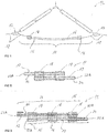
- FIG. 3 shows an embodiment according to the invention, which is illustrated with the aid of 2-layer conductor cables 12:
- the inner layer 22A is exposed in the end regions 16, ie the outer layer 24 has been removed in the region of the cable end.
- a cable clamp 18 of a first type is attached, which connects the inner layer 22A of a conductor cable with the outer layer 24 of the other conductor cable 12 directly electrically connects.
- at least one (preferably two) further cable clamp 18 of a sixth type is attached, which connects the two outer layers 24 electrically to one another directly.
- the respective cable clamp 18 clamps the respective position.
- this therefore has different clamping diameters on the one hand for the inner layer 22A and on the other hand for the outer layer 24.
- the number of cable clamps 18 can be varied and adapted to the respective loop connection and the conductor cables 12, as is exemplarily shown below in connection with a three-layer and a four-layer conductor cable 12.
- the cable connection 10 described here can be adapted to any multi-layer conductor cable.
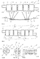
- the upper half of the Figure 4 serves to explain the various cable clamps 18, five cable clamps 18 being indicated in this explanatory illustration.
- the typical real installation situation for an overhead line 14 is shown in the lower half of the picture.
- a group of cable clamps 18 is attached to each end region 16 of the respective conductor cable 12, the two groups being spaced from one another.
- Each group has (finally) the cable clamps 18 of the first, fourth and sixth types, as described above.
- one or more spacers are generally provided, which are attached between the spaced apart cable clamps 18, that is to say in particular between the two groups.
- the two conductor cables 12 are kept at a distance from one another in this intermediate region and in particular are guided parallel to one another by means of these.
- the cable connections 10 according to the invention are also designed in the manner of a loop connection between two guy clamps 17 and suspended via a guy device not shown here.
- the ends of the rope of the two conductor cables 12 typically overlap over several meters.
- the respective third inner layer 22C is also connected to the outer layer 24 of the other conductor cable 12.
- Such a 4-layer conductor cable 12 has 72 wires, for example, with the sequence 9 wires in the first inner layer 22A, 15 wires in the second inner layer 22B, 21 wires in the third inner layer 22C and 27 wires in the outer layer 24.
- a branching conductor 44 is electrically and mechanically attached to a continuous conductor 12.
- a short auxiliary conductor cable 46 is additionally provided, which is connected on the one hand to the continuous conductor cable 12 and on the other hand to the branching conductor 44.
- the branching conductor 44 is also connected to the continuous conductor 12.
- End caps 38 are attached to each of the front ends of the auxiliary conductor cable 44 and the branching conductor cable 44.
- the current from each conductor layer is given the opportunity to pass directly to the other conductor cable 12, 44, 46 via a respective cable clamp 18.
- the cable connection 10 is particularly suitable for the connection of two conductor cables 12 in the manner of a loop connection to form an entire continuous conductor cable, which is therefore in particular stretched between two guy masts of an overhead line.
- this cable connection 10 is also suitable for current branches in which a branching conductor cable 44 branches off from a continuous conductor cable 12.
Landscapes
- Cable Accessories (AREA)
Abstract
Die Seilverbindung (10) insbesondere einer elektrischen Freileitung (14) dient zur mechanischen und elektrischen Verbindung zwischen zwei Leiterseilen (12, 44) mit Hilfe von mehreren Seilklemmen (18), wobei jedes der Leiterseile (12, 44) zumindest zwei konzentrisch zueinander angeordnete Lagen an Drähten aufweisen, nämlich zumindest eine Innenlage (22A, B, C) und eine Außenlage (24), wobei über zumindest eine der Seilklemmen (18) die zumindest eine Innenlage (22A, B, C) des einen Leiterseils (12,44) geklemmt und über die Seilklemme (18) unmittelbar mit dem anderen Leiterseil (12,44) elektrisch verbunden ist. Hierdurch ist unter anderem eine homogene Stromverteilung über die mehreren Lagen der Leiterseile (12) im Bereich der Seilverbindung (10) erreicht.The cable connection (10) in particular an electrical overhead line (14) is used for the mechanical and electrical connection between two conductor cables (12, 44) with the aid of several cable clamps (18), each of the conductor cables (12, 44) having at least two concentric layers of wires, namely at least one inner layer (22A, B, C) and one outer layer (24), with the at least one inner layer (22A, B, C) of the one conductor cable (12, 44) via at least one of the cable clamps (18) clamped and electrically connected directly to the other conductor cable (12, 44) via the cable clamp (18). This achieves, among other things, a homogeneous current distribution over the several layers of the conductor cables (12) in the area of the cable connection (10).
Description
Die Erfindung betrifft eine Seilverbindung insbesondere einer elektrischen Freileitung mit den Merkmalen des Oberbegriffs des Anspruchs 1 sowie ein Set bestehend aus mehreren Seilklemmen für eine derartige Seilverbindung.The invention relates to a cable connection, in particular an electrical overhead line, with the features of the preamble of claim 1 and a set consisting of several cable clamps for such a cable connection.
Freileitungen dienen dem Transport von elektrischer Energie. Es wurden im letzten Jahrhundert unterschiedlichste Freileitungen in den verschiedensten Spannungsebenen errichtet. Aus verschiedenen Gründen (z. B. Liberalisierung des Strommarktes, Stilllegung von alten Kraftwerken, Einspeisung von Energie aus Windkraftwerken) haben sich in der jüngeren Vergangenheit die Lastflüsse in den Hochspannungsnetzen gravierend verändert. Dabei ist festzustellen, dass die Auslastung des Netzes ständig steigt, so dass die Betriebsströme zeitweise in Leitungen des Netzes die zulässigen Ströme erreichen. Aufgrund neuer Leitertypen, wie beispielsweise HTLS (Hochtemperaturleiterseile), sind auch die Anforderungen, an die zur Verbindung der Leiterseile verwendeten Armaturen erheblich größer geworden. Um einen durchgehenden Leiter zu erreichen, müssen bei der Montage einer Freileitung aufgrund der begrenzten Längen der beispielsweise auf Trommeln bereitgestellten Leiterseile diese über eine Seilverbindung miteinander verbunden werden.Overhead lines are used to transport electrical energy. In the last century, a wide variety of overhead lines were built in the most varied of voltage levels. For various reasons (e.g. liberalization of the electricity market, shutdown of old power plants, feed-in of energy from wind power plants), the load flows in the high-voltage networks have changed significantly in the recent past. It should be noted that the utilization of the network is constantly increasing, so that the operating currents in the network's lines sometimes reach the permissible currents. Due to new types of conductors, such as HTLS (high temperature conductor cables), the requirements for the fittings used to connect the conductor cables have also increased considerably. In order to achieve a continuous conductor, when installing an overhead line, due to the limited lengths of the conductor cables provided, for example, on drums, these cables must be connected to one another via a cable connection.
Zur Seilverbindung zweier Leiterseile ist grundsätzlich die in
Bei dieser Seilverbindung 10 werden zwei Leiterseile 12 von zwei aufeinanderfolgenden Abspannabschnitten einer elektrischen (Frei-)Leitung 14 elektrisch miteinander verbunden. Hierzu werden Endbereiche 16 der beiden Leiterseile 12 über mehrere Seilklemmen 18 elektrisch und mechanisch miteinander verbunden. In einer in Deutschland häufig vorkommenden Variante werden die Seilenden ungeschnitten durch Abspannklemmen 17 geführt. In der dadurch gebildeten, zugentlasteten Stromschlaufe überlappen dabei die beiden Seilenden über einen Bereich von mehreren Metern. Die beiden Leiterseile 12 werden mindestens an den Enden des Überlappungsbereiches mit den als Schalenstromklemmen ausgebildeten Seilklemmen 18 elektrisch leitend miteinander verbunden. Die beiden Abspannklemmen 17 und damit die Seilverbindung 10 ist über eine Abspanneinrichtung an einem nicht näher dargestellten Aufhängepunkt, beispielsweise an einem Freileitungsmast befestigt.In this
Die Leiterseile 12 sind in der Regel als Spiralseile aus konzentrisch in mehreren Lagen verseilten Drähten aufgebaut. Die Drähte bestehen typischerweise aus Aluminium. Diese bilden an ihrer Oberfläche eine Oxidschicht aus, welche bei der Seilverbindung zu Problemen und beispielsweise zu einer thermischen Belastung führen kann, da der Strom über sogenannte Querkontakte von dem einen Leiterseil 12 in das andere Leiterseil 12 übergehen muss.The
Ausgehend hiervon liegt der Erfindung die Aufgabe zu Grunde, bei einer Seilverbindung insbesondere einer Freileitung eine gute elektrische Verbindung zwischen den beiden zu verbindenden Leiterseilen zu gewährleisten.Proceeding from this, the invention is based on the object of ensuring a good electrical connection between the two conductor cables to be connected in a cable connection, in particular an overhead line.
Die Aufgabe wird gemäß der Erfindung gelöst durch eine Seilverbindung insbesondere einer elektrischen Freileitung zwischen zwei Leiterseilen mit Hilfe von mehreren Seilklemmen, wobei jedes der Leiterseile zumindest zwei konzentrisch zueinander angeordnete Lagen an Drähten aufweist, nämlich zumindest eine Innenlage und eine Außenlage, wobei über zumindest eine der Seilklemmen die zumindest eine Innenlage des einen Leiterseils geklemmt und über die Seilklemme unmittelbar mit dem anderen Leiterseil elektrisch verbunden ist.The object is achieved according to the invention by a cable connection, in particular an electrical overhead line between two conductor cables with the aid of several cable clamps, each of the conductor cables having at least two concentrically arranged layers of wires, namely at least one inner layer and one outer layer, with at least one of the Cable clamps the at least one inner layer of one conductor is clamped and is directly electrically connected to the other conductor cable via the cable clamp.
Bei den Leiterseilen handelt es sich allgemein um in mehreren Lagen miteinander verseilte blanke elektrisch leitende (Metall-) Drähte, also ohne Drahtisolierung. Speziell werden Aluminiumdrähte eingesetzt.The conductor cables are generally bare electrically conductive (metal) wires stranded together in several layers, i.e. without wire insulation. Aluminum wires are used in particular.
Die Seilklemmen sind insbesondere nach Art von sogenannten Parallelkanalklemmen ausgebildet, bei denen zwei Klemmkanäle parallel zur Längsrichtung der Leiterseile und nebeneinander angeordnet sind. Bei diesen Seilklemmen wird daher unmittelbar eine Innenlage des einen Leiterseils elektrisch mit dem anderen Leiterseil verbunden. Mit der Seilklemme wird daher die Innenlage direkt geklemmt, im Klemmbereich sind daher die Außenlage und ggf. weitere Innenlagen entfernt, um die unmittelbare Klemmung der Innenlage zu ermöglichen.The cable clamps are designed in particular in the manner of so-called parallel channel clamps, in which two clamping channels are arranged parallel to the longitudinal direction of the conductor cables and next to one another. In the case of these cable clamps, an inner layer of one conductor cable is therefore directly electrically connected to the other conductor cable. The inner layer is therefore clamped directly with the rope clamp; the outer layer and, if necessary, further inner layers are therefore removed in the clamping area in order to enable the inner layer to be clamped directly.
Durch diese Ausgestaltung wird der besondere Vorteil erzielt, dass der Strom von den Drähten der Innenlage nicht über Querströme zunächst über die Außenlage nach außen geleitet werden muss. Durch die unmittelbare Klemmung der Innenlage sind die elektrischen Widerstände geringer und damit die elektrische Kontaktierung verbessert. Weiterhin ist hierdurch die Stromverteilung auch homogen, da kein Ausweichen des Stroms von der Innenlage in die Außenlage erforderlich ist.This configuration achieves the particular advantage that the current from the wires of the inner layer does not have to be first conducted to the outside via cross currents via the outer layer. As a result of the direct clamping of the inner layer, the electrical resistances are lower and thus the electrical contact is improved. Furthermore, the current distribution is also homogeneous as a result, since the current does not need to be diverted from the inner layer to the outer layer.
Diese Ausgestaltung beruht auf der Überlegung, dass zur Führung des Leiterstroms im Leiterseil zunächst der Leitquerschnitt aller verseilten (Aluminium) Drähte zur Verfügung steht. Durch die Vielzahl der Querkontakte der verseilten Drähte in einem ungestörten Abspannabschnitt der Freileitung vergleichmäßigt sich die Stromverteilung im Leitquerschnitt, so dass die Stromdichte in allen Aluminiumdrahtquerschnitten gleich und homogen ist. Im Bereich der Seil- oder Stromschlaufenverbindung bildet sich jedoch bei herkömmlichen Seilverbindungen notwendigerweise ein inhomogenes Strömungsfeld in den Drähten aus, weil der Strom von dem einen auf das andere Leiterseil übergeht. Dieses Strömungsfeld und die damit verbundenen Stromdichten in den Einzeldrähten hängen von den elektrischen Querwiderständen zwischen den Einzeldrähten ab. Der Werkstoff Aluminium bildet bekanntermaßen an Oberflächen sehr schnell eine passivierende Oxidschicht. Wenn Aluminiumdrähte längere Zeit der Witterung ausgesetzt sind und/oder während der Herstellung wärmebehandelt werden, wächst die Dicke der Oxidschicht. Die Oxidschichten und Schmutzablagerungen bilden nichtleitende Fremdschichten an den Drahtoberflächen. Diese Schichten behindern einen Stromübergang zwischen einzelnen Drahtlagen und wirken wie ein Querwiderstandsbelag. Selbst kleine Ströme über hohe Querwiderstände können zu hohen Verlustleistungen und damit verbunden zu thermischer Überbelastung an den Klemmen führen.This configuration is based on the consideration that the conductor cross-section of all stranded (aluminum) wires is initially available to guide the conductor current in the conductor cable. Due to the large number of cross contacts of the stranded wires in an undisturbed tensioning section of the overhead line, the current distribution in the conductor cross-section is evened out, so that the current density in all aluminum wire cross-sections is the same and homogeneous. In the area of the cable or current loop connection, however, with conventional cable connections, an inhomogeneous flow field necessarily forms in the wires because the current passes from one conductor to the other. This flow field and the associated current densities in the individual wires depend on the electrical transverse resistances between the individual wires. As is well known, aluminum forms a passivating oxide layer on surfaces very quickly. When aluminum wires are exposed to the elements for a long time and / or are heat-treated during manufacture, the thickness of the oxide layer increases. The oxide layers and dirt deposits form non-conductive foreign layers on the wire surfaces. These layers hinder a current transfer between individual wire layers and act like a cross-resistance layer. Even small currents through high transverse resistances can lead to high power losses and the associated thermal overload at the terminals.
Bei der herkömmlichen Stromschlaufenverbindung mit den lediglich die Außenlagen der Leiterseile kontaktierenden Seilklemmen erfolgt der Fluss des Gesamtstroms über den Strompfad "äußere Drahtlage (Außenlage) des einen Leiterseils - Klemmstücke der Seilklemme - äußere Drahtlage (Außenlage) des zweiten Leiterseils". Der Strom der Innenlagen muss daher von den Innenlagen auf die Außenlagen übergehen, bzw. wieder in die Innenlagen übergehen. Die Kontaktierung der Innenlagen und damit die Beteiligung der Innenlagen an der Stromübertragung im unmittelbaren Bereich der Seilklemmen ist dabei stark von dem Querwiderstandsbelag zwischen den Leiterlagen abhängig. Bei der Montage der Seilklemmen werden typischerweise die Außenlagen der Leiterseile und die Leiterkanäle (Klemmkanäle) der Seilklemmen mit Drahtbürsten metallisch blank gebürstet, um die Oxidschichten aufzubrechen und eine gute elektrische Kontaktierung zwischen Leiterseil-Außenlagen und den Klemmstücken zu ermöglichen. Die innenliegenden Aluminiumdrahtlagen werden herkömmlich in der Regel wegen der schlechten Zugänglichkeit nicht gereinigt, so dass der oben beschriebene Querwiderstandsbelag resultierend aus den Querwiderständen zwischen den verseilten Drähten bei herkömmlichen Seilverbindungen hoch ist.In the conventional current loop connection with the cable clamps that only contact the outer layers of the conductor cables, the flow of the total current takes place via the current path "outer wire layer (outer layer) of one conductor cable - clamping pieces of the cable clamp - outer wire layer (outer layer) of the second conductor cable". The flow of the inner layers must therefore pass from the inner layers to the outer layers or again into the inner layers. The contacting of the inner layers and thus the participation of the inner layers in the power transmission in the immediate area of the cable clamps is heavily dependent on the transverse resistance layer between the conductor layers. When assembling the cable clamps, the outer layers of the conductor cables and the conductor channels (clamping channels) of the cable clamps are typically brushed to a bare metal with wire brushes in order to break up the oxide layers and enable good electrical contact between the conductor cable outer layers and the clamping pieces. The internal aluminum wire layers are conventionally not cleaned because of their poor accessibility, so that the above-described transverse resistance coating is high as a result of the transverse resistance between the stranded wires in conventional rope connections.
Mit steigendem Querwiderstand versucht der Strom diesen Widerstand zu umgehen, indem der Strom, welcher gemäß der entsprechenden Querschnittsflächenanteile in den inneren Leiterlagen fließt, bei herkömmlichen Seilverbindungen schon deutlich vor der eigentlichen Seilverbindung teilweise in die Außenlage des Leiterseils wechselt und sich dort konzentriert. Die daraus resultierende höhere Stromdichte in der Außenlage steigert die thermische Belastung des Seilabschnittes und der angrenzenden Armaturen sowie der Seilklemmen. Der verbleibende Strom der weiterhin in den inneren Leiterlagen bleibt und an den Klemmen von Innenlage auf Außenlage übergehen muss, erzeugt auf Grund des hohen Querwiderstandes unmittelbar an den Klemmen Leistungsverlustspitzen die wiederum eine zusätzliche thermische Belastung für die Klemmen darstellen.With increasing transverse resistance, the current tries to bypass this resistance by partially changing the current, which flows in the inner conductor layers according to the corresponding cross-sectional area proportions, to the outer layer of the conductor cable well before the actual cable connection and concentrates there. The resulting higher current density in the outer layer increases the thermal load on the rope section and the adjacent fittings as well as the rope clamps. The remaining one Current that remains in the inner conductor layers and has to pass from the inner layer to the outer layer at the terminals, generates power loss peaks directly at the terminals due to the high transverse resistance, which in turn represent an additional thermal load for the terminals.
Demzufolge konzentriert sich der Strom in der Außenlage des einen Leiterseils, geht über die Seilklemme auf das zweite Leiterseil über, und konzentriert sich dort (zunächst) wieder in der Außenlage. Bei großen Querwiderständen zwischen den Drahtlagen hat die Anzahl der für eine Seilverbindung verwendeten herkömmlichen Seilklemmen nur geringen Einfluss auf die Stromaufteilung in den einzelnen Lagen. Dieser Effekt beschränkt sich nicht auf Leiterseile mit zwei Drahtlagen, sondern kann bei beliebig viellagigen Leiterseilen auftreten. Bei drei- oder mehrlagigen Leiterseilen verstärkt sich der Effekt sogar, da die Querschnittsfläche der Außenlage im Verhältnis zu den Innenlagen kleiner wird und dadurch die Stromdichte bei großen Querwiderstandsbelägen im Leiterseil in der Außenlage noch stärker zunimmt.As a result, the current is concentrated in the outer layer of one conductor, passes over the cable clamp to the second conductor, and there (initially) concentrates again in the outer layer. In the case of large transverse resistances between the wire layers, the number of conventional cable clamps used for a cable connection has only a minor influence on the current distribution in the individual layers. This effect is not limited to conductors with two layers of wire, but can occur with any number of layers of conductors. In the case of three-layer or multi-layer conductor cables, the effect is even increased, since the cross-sectional area of the outer layer becomes smaller in relation to the inner layers and, as a result, the current density increases even more with large cross-resistance layers in the conductor cable in the outer layer.
Durch die erfindungsgemäße Ausgestaltung wird demgegenüber eine homogene Verteilung der Stromdichte über die einzelnen Lagen hinweg begünstigt, d.h. im Vergleich zu der herkömmlichen Seilverbindung wird eine Vergleichmäßigung der Stromdichte erreicht. Dadurch ist die Seilverbindung insbesondere auch für hohe Stromlasten sowie für Leiterseile mit erhöhten Querwiderständen zwischen den einzelnen Leiterseilen ausgebildet. Speziell ist die Seilverbindung für Leiterseile mit höheren zulässigen (Dauer-) Betriebstemperaturen (insbesondere >80°C) ausgebildet und es werden vorzugsweise derartige (HTLS) Leiterseile eingesetzt. Weiterhin ist eine Verringerung oder Vermeidung von Zwischenlagenströmen oder Querströmen zwischen den einzelnen Drähten und Lagen erreicht.By contrast, the configuration according to the invention promotes a homogeneous distribution of the current density over the individual layers, i.e., compared to the conventional cable connection, the current density is made more uniform. As a result, the cable connection is designed in particular for high current loads as well as for conductor cables with increased transverse resistance between the individual conductor cables. The cable connection is specially designed for conductor cables with higher permissible (continuous) operating temperatures (in particular> 80 ° C.) and such (HTLS) conductor cables are preferably used. Furthermore, a reduction or avoidance of interlayer currents or cross-currents between the individual wires and layers is achieved.
Die Seilverbindung wird bevorzugt bei einer elektrische Freileitung eingesetzt. Eine solche weist allgemein mehrere durch Seile gebildete Leiter auf, die zwischen Tragmasten abgespannt sind. Die beiden Leiterseile verlaufen - im Falle einer Schlaufenverbindung mit den zwei miteinander verbundenen Teilstücken (die beiden Leiterseile) des jeweiligen durchgehenden und abgespannten Seils - in Längsrichtung der Freileitung und überlappen sich im Bereich der Seilverbindung typischerweise über einen Bereich von zumindest 0,5m oder von zumindest 1m. Es sind typischerweise zumindest zwei Seilklemmen oder zwei Gruppen von Seilklemmen vorgesehen, wobei die eine Seilklemme (Gruppe von Seilklemmen) einen Endbereich des einen Leiterseils und einen Zwischenabschnitt des anderen Leiterseils klemmt.The cable connection is preferably used in an electrical overhead line. Such generally has a plurality of conductors formed by ropes, which are guyed between support masts. The two conductor ropes run - in the case of a loop connection with the two interconnected sections (the two conductor ropes) of the respective continuous and guyed rope - in In the longitudinal direction of the overhead line and typically overlap in the area of the cable connection over an area of at least 0.5 m or at least 1 m. At least two cable clamps or two groups of cable clamps are typically provided, the one cable clamp (group of cable clamps) clamping an end region of one conductor cable and an intermediate section of the other conductor cable.
Gemäß einer bevorzugten Ausgestaltung werden über zumindest eine der Seilklemmen unterschiedliche Lagen der beiden Leiterseile geklemmt und damit unmittelbar über die Seilklemme elektrisch miteinander kontaktiert. Durch diese Ausgestaltung wird also ein Stromfluss direkt über die Seilklemme zwischen unterschiedlichen Lagen der beiden Leiterseile bewirkt, was zusätzlich die gewünschte Vergleichmäßigung der Stromdichte im Bereich der Seilverbindung unterstützt.According to a preferred embodiment, different layers of the two conductor cables are clamped via at least one of the cable clamps and thus electrically contacted with one another directly via the cable clamp. With this configuration, a current flow is brought about directly via the cable clamp between different layers of the two conductor cables, which additionally supports the desired equalization of the current density in the area of the cable connection.
Während beispielsweise bei einer ersten Ausführungsvariante ausschließlich gleiche Lagen der beiden Leiterseile über eine jeweilige Seilklemme miteinander kontaktiert werden, beispielsweise eine Innenlage mit einer Innenlage und eine Außenlage mit einer Außenlage, ist bei dieser zweiten Ausführungsvariante vorgesehen, dass unterschiedliche Lagen der beiden Leiterseile miteinander kontaktiert werden. Hierbei werden entweder ausschließlich unterschiedliche Lagen miteinander kontaktiert oder es werden ergänzend auch gleiche Lagen miteinander kontaktiert und damit Querströme zwischen den Lagen verringert.For example, while in a first variant only the same layers of the two conductor cables are contacted with one another via a respective cable clamp, for example an inner layer with an inner layer and an outer layer with an outer layer, this second embodiment variant provides that different layers of the two conductor cables are contacted with one another. In this case, either only different layers are contacted with one another or, in addition, identical layers are also contacted with one another, thus reducing cross currents between the layers.
In bevorzugter Ausgestaltung werden daher mehrere und vorzugsweise jede Lage des einen, ersten Leiterseils in dessen Endbereich jeweils über eine jeweilige Seilklemme geklemmt und über diese Seilklemme mit dem anderen, zweiten Leiterseil elektrisch kontaktiert. Vorzugsweise werden quasi symmetrisch hierzu auch mehrere und insbesondere alle Lagen des anderen, zweiten Leiterseils - in dessen Endbereich - ebenfalls über eine jeweilige weitere Seilklemme geklemmt und mit dem ersten Leiterseil elektrisch leitend verbunden. Durch diese Maßnahme werden daher individuell die einzelnen Lagen des jeweiligen Leiterseils über die Seilklemmen geklemmt und mit dem anderen Leiterseil verbunden. Es wird also jede (Aluminium-) Drahtlage der beiden zu verbindenden Leiterseile einzelnen mit einer jeweiligen Seilklemme geklemmt und mit dem jeweils anderen Leiterseil elektrisch kontaktiert.In a preferred embodiment, therefore, several and preferably each layer of the one, first conductor cable is clamped in its end area via a respective cable clamp and electrically contacted with the other, second conductor cable via this cable clamp. Preferably, more or less symmetrically to this, several and in particular all layers of the other, second conductor cable - in its end area - are also clamped via a respective further cable clamp and are connected to the first conductor cable in an electrically conductive manner. This measure therefore individually clamps the individual layers of the respective conductor cable over the cable clamps and connects them to the other conductor cable. So each (aluminum) wire layer of the two conductor cables to be connected is individually with it clamped to a respective cable clamp and electrically contacted with the respective other conductor cable.
Das zumindest eine Leiterseil wird daher in seinem Endbereich von mehreren Seilklemmen geklemmt, wobei die verschiedenen Seilklemmen unterschiedliche Lagen des einen Leiterseils klemmen und diese direkt mit dem anderen Leiterseil verbinden. Bevorzug erfolgt dies in gleicher Weise im Endbereich des anderen Leiterseils.The at least one conductor cable is therefore clamped in its end area by a plurality of cable clamps, the different cable clamps clamping different layers of one conductor cable and connecting them directly to the other conductor cable. This is preferably done in the same way in the end area of the other conductor cable.
Die Seilverbindung ist dabei insbesondere nach einigen und vorzugsweise nach allen der folgenden Kriterien ausgebildet:
- vergleichbare Leitquerschnitte, also insbesondere vergleichbare Lagenquerschnitte werden über die Seilklemme miteinander elektrisch kontaktiert insbesondere derart, dass:
- die Stromverteilung in den Leitern der Seilverbindung möglichst gleichmäßig ist,
- die Stromdichte über alle Lagen möglichst gleichmäßig ist,
- Querströme möglichst über die Seilklemme fließen
- Querströme zwischen den einzelnen Drahtlagen außerhalb und innerhalb der Seilklemme möglichst gering sind
- Comparable conductive cross-sections, i.e. in particular comparable layer cross-sections, are electrically contacted with one another via the cable clamp, in particular in such a way that:
- the current distribution in the conductors of the cable connection is as even as possible,
- the current density is as uniform as possible over all layers,
- Cross currents should flow as far as possible over the rope clamp
- Cross currents between the individual wire layers outside and inside the rope clamp are as low as possible
Die Seilklemmen weisen bevorzugt zwei parallel zueinander verlaufende Klemmkanäle zum Klemmen der beiden Leiterseile auf. Die Klemmkanäle bilden Klemmbereiche und sind an die Durchmesser der jeweiligen Lagen der zu verbindenden Leiterseile angepasst, um die Lagen möglichst vollumfänglich zu kontaktieren. Eine an den Lagendurchmesser angepasste nahezu vollumfängliche Umfassung stellt bei montagegerechter Reinigung der Leiteroberfläche und der Klemmkanäle eine gute, langzeitstabile elektrische Kontaktierung sicher und wirkt dabei auch noch Kriecheffekten entgegen. Die Seilklemmen weisen allgemein typischerweise zwei (Halb-) Schalen auf, die gegeneinander z.B. mit Hilfe von Schrauben verspannt sind. Die Schalen bilden dabei die Klemmkanäle aus, in denen die Leiterseile geklemmt sind.The cable clamps preferably have two clamping channels running parallel to one another for clamping the two conductor cables. The clamping channels form clamping areas and are adapted to the diameter of the respective layers of the conductor cables to be connected in order to contact the layers as fully as possible. Almost all of the surrounding area adapted to the layer diameter ensures good, long-term stable electrical contact when the conductor surface and the clamping channels are cleaned properly for assembly and also counteracts creep effects. The cable clamps generally have two (half) shells which are braced against one another, for example with the aid of screws. The shells form the clamping channels in which the conductor cables are clamped.
Um den Kriecheffekten noch weiter entgegen zu wirken, sind vorzugsweise Spannscheiben insbesondere sowohl schraubenkopfseitig als auch mutterseitig mit Stahlunterlegscheiben in den Schraubenverbindungen montiert, welche die beiden Hälften der Seilklemme zusammenhalten.In order to counteract the creep effects even further, tension washers are preferably mounted in the screw connections, in particular both on the screw head side and on the nut side, with steel washers, which hold the two halves of the cable clamp together.
Sofern vorliegend von "Seilklemme" gesprochen wird, so werden hierunter vorzugsweise einzelne Baueinheiten verstanden, welche jeweils pro Klemmkanal / Klemmbereich einen an die eine zu klemmende Lage angepassten und in der Regel über die Länge des Klemmbereichs konstanten Durchmesser aufweisen. Dies bedeutet, dass in einem jeweiligen Endbereich mehrere solcher einzelner, die Seilklemmen bildende Baueinheiten, befestigt sind.If the term "rope clamp" is used in the present case, this is preferably understood to mean individual structural units which, per clamping channel / clamping area, have a diameter that is adapted to the one position to be clamped and, as a rule, constant over the length of the clamping area. This means that several such individual structural units forming the cable clamps are fastened in a respective end region.
Alternativ hierzu wird unter dem Begriff "Seilklemme" auch ein Teilbereich einer mehrstufigen und eine Baueinheit bildenden Klemme verstanden, bei der in Längsrichtung des zumindest einen Leiterseils betrachtet mehrere Klemmbereiche mit unterschiedlichen Durchmessern zum Klemmen unterschiedlicher Lagen des Leiterseils ausgebildet sind. Bei einem n-lagigen Leiterseil weist die mehrstufige Klemme beispielsweise n-Klemmstufen für n unterschiedliche Klemmdurchmesser auf. Der Klemmkanal ist daher gestuft mit unterschiedlichen Klemmdurchmessern ausgebildet, wobei in Längsrichtung zum Seilende hin die Durchmesser der Stufen abnehmen. Der parallel daneben angeordnete zweite Klemmkanal für das andere Leiterseil ist vorzugsweise ebenfalls gestuft ausgebildet, jedoch gegenläufig zu dem ersten Klemmkanal. Dies ermöglicht beispielsweise bei einem zweilagigen Leiterseil und nur einer Klemmen-Baueinheit, dass die Innenlage des ersten Leiterseils mit der Außenlage des zweiten Leiterseils, die beiden Außenlagen miteinander und die Außenlage des ersten Leiterseils mit der Innenlage des zweiten Leiterseils über einen jeweiligen Klemmbereich miteinander verbunden sind. Auch ist ergänzend eine Ausgestaltung vorgesehen, bei der in einem mittleren Klemmbereich die beiden Innenlagen und in zwei äußeren Klemmbereichen jeweils die Außenlage nur eines der Leiterseils geklemmt wird.As an alternative to this, the term "cable clamp" is also understood to mean a sub-area of a multi-stage clamp forming a structural unit, in which several clamping areas with different diameters are formed for clamping different layers of the conductor cable, viewed in the longitudinal direction of the at least one conductor cable. In the case of an n-layer conductor, the multi-stage clamp has, for example, n-clamping steps for n different clamping diameters. The clamping channel is therefore designed stepped with different clamping diameters, the diameters of the steps decreasing in the longitudinal direction towards the end of the rope. The second clamping channel for the other conductor cable, which is arranged in parallel next to it, is preferably also stepped, but in the opposite direction to the first clamping channel. In the case of a two-layer conductor cable and only one terminal assembly, for example, this enables the inner layer of the first conductor cable to be connected to the outer layer of the second conductor cable, the two outer layers to one another and the outer layer of the first conductor cable to the inner layer of the second conductor cable via a respective clamping area . In addition, an embodiment is provided in which the two inner layers are clamped in a central clamping area and the outer layer of only one of the conductor cables is clamped in each of two outer clamping areas.
In bevorzugter Ausgestaltung ist jeweils zumindest eine Innenlage des einen Leiterseils mit der Außenlage des anderen Leiterseils mittels jeweils einer der Seilklemmen geklemmt und elektrisch leitend verbunden.In a preferred embodiment, at least one inner layer of the one conductor is clamped and electrically conductively connected to the outer layer of the other conductor by means of one of the cable clamps.
Zur Klemmung einer jeweiligen Innenlage ist wie bereits erwähnt allgemein vorgesehen, dass im Klemmbereich die die Innenlage umgebende nächste Lage oder die die Innenlage umgebenden nächsten Lagen entfernt sind. Ein jeweiliges Leiterseil ist daher am Ende quasi abgemantelt, d. h. eine oder mehrere der äußeren Lagen sind beispielsweise auch in mehreren sukzessiven Stufen entfernt. Vorzugsweise ist daher am jeweiligen Ende eines Leiterseils jede der Innenlagen sukzessive frei gelegt, so dass der Endbereich eine (mehrfach) gestufte Ausgestaltung aufweist. Die freigelegten Innenlagen sind über die jeweilige Seilklemme geklemmt und mit einer der Lagen, beispielsweise mit der Außenlage des anderen Leiterseils elektrisch kontaktiert. Diese Lage des anderen Leiterseils ist in dem zweiten Klemmbereich geklemmt.In order to clamp a respective inner layer, it is generally provided, as already mentioned, that the next layer surrounding the inner layer or the next layers surrounding the inner layer are removed in the clamping area. A respective conductor cable is therefore quasi stripped at the end, i. H. one or more of the outer layers are also removed in several successive stages, for example. Preferably, therefore, each of the inner layers is exposed successively at the respective end of a conductor cable, so that the end region has a (multiple) stepped configuration. The exposed inner layers are clamped over the respective cable clamp and electrically contacted with one of the layers, for example with the outer layer of the other conductor cable. This layer of the other conductor is clamped in the second clamping area.
So sind beispielsweise bei einem mehr als zweilagigen Aufbau zumindest zwei und vorzugsweise alle Innenlagen sowie vorzugsweise auch ergänzend die Außenlage des einen Leiterseils mit jeweils einer Seilklemme geklemmt und mit einer jeweiligen Lage, vorzugsweise mit der Außenlage des anderen Leiterseils verbunden.For example, in a more than two-layer structure, at least two and preferably all of the inner layers and preferably also the outer layer of one conductor are clamped with a cable clamp and connected to a respective layer, preferably to the outer layer of the other conductor.
In zweckdienlicher Ausgestaltung ist bei einer Variante mit zumindest zwei und vorzugsweise mit zumindest oder genau drei Innenlagen vorgesehen, dass eine Innenlage des einen Leiterseils mit einer Innenlage des anderen Leiterseils über eine jeweilige Seilklemme elektrisch kontaktiert ist. Vorzugsweise sind dabei die äußersten Innenlagen miteinander elektrisch kontaktiert.In an expedient embodiment, in a variant with at least two and preferably at least or exactly three inner layers, it is provided that an inner layer of one conductor cable is electrically contacted with an inner layer of the other conductor cable via a respective cable clamp. The outermost inner layers are preferably electrically contacted with one another.
Bevorzugt werden bis zu einem dreilagigen Leiterseil die Innenlagen nur mit der Außenlage des anderen Leiterseils verbunden. Bei einem Leiterseil mit insgesamt oder zumindest vier Lagen, also zumindest oder genau drei Innenlagen, sind in bevorzugter Ausgestaltung die inneren Innenlagen jeweils mit der Außenlage des anderen Leiterseils verbunden und die äußersten Innenlagen der beiden Leiterseile sind miteinander verbunden. Bevorzugt ist hierbei keine direkte Kontaktierung zwischen den beiden Außenlagen vorgesehen.Up to a three-layer conductor, the inner layers are preferably only connected to the outer layer of the other conductor. In a conductor cable with a total of or at least four layers, i.e. at least or exactly three inner layers, in a preferred embodiment the inner inner layers are each connected to the outer layer of the other conductor cable and the outermost inner layers of the two conductor cables are connected to each other. In this case, there is preferably no direct contact between the two outer layers.
Vorzugsweise sind gleiche Innenlagen, also Innenlagen einer gleichen Stufe miteinander verbunden. Derartige gleiche Innenlagen oder Innenlagen gleicher Stufe weisen dabei einen gleichen Lagendurchmesser auf. Durch die endseitige sukzessive Freilegung und Abmantelung der Innenlagen weist das Seilende allgemein eine gestufte Ausgestaltung auf, wobei in einer jeweiligen Stufe eine jeweilige Innenlage freigelegt ist. Die erste Stufe definiert dabei die erste, innerste Innenlage, die zweite Stufe definiert die diese erste Innenlage umgebende zweite Innenlage, die dritte Stufe die diese wiederum umgebende (Innen-) Lage usw. Die letzte Stufe wird jeweils durch die Außenlage gebildet.The same inner layers, that is to say inner layers of the same step, are preferably connected to one another. Such identical inner layers or inner layers of the same step have the same layer diameter. As a result of the end-side successive exposure and stripping of the inner layers, the rope end generally has a stepped configuration, with a respective inner layer being exposed in a respective step. The first stage defines the first, innermost inner layer, the second stage defines the second inner layer surrounding this first inner layer, the third stage the (inner) layer surrounding it, etc. The last stage is each formed by the outer layer.
Wie bereits erwähnt sind vorzugsweise zwei Gruppen von mehreren Seilklemmen vorgesehen. Eine jede Gruppe ist in einem Endbereich des jeweiligen Leiterseils angeordnet. Neben dem Endbereich weist das jeweilige Leiterseil einen Zwischenbereich auf, wobei in der Regel die eine Gruppe den Endbereich des ersten Leiterseils und den Zwischenbereich des zweiten Leiterseils klemmt und die andere Gruppe den Endbereich des zweiten Leiterseils und den Zwischenbereich des ersten Leiterseils klemmt. Die Endbereiche sind dabei typischerweise jeweils gestuft ausgebildet, d. h. in den Endbereichen ist zumindest eine und sind vorzugsweise alle Innenlagen freigelegt.As already mentioned, two groups of several rope clamps are preferably provided. Each group is arranged in an end area of the respective conductor cable. In addition to the end area, the respective conductor cable has an intermediate area, with one group generally clamping the end area of the first conductor cable and the intermediate area of the second conductor cable and the other group clamping the end area of the second conductor cable and the intermediate area of the first conductor cable. The end regions are typically designed in a stepped manner, i. H. at least one and preferably all of the inner layers are exposed in the end regions.
In dem Zwischenbereich ist gemäß einer ersten Ausführungsvariante keine Innenlage frei gelegt.According to a first variant, no inner layer is exposed in the intermediate area.
Alternativ kann auch der Zwischenbereich sich in einen Bereich erstrecken, in dem eine Innenlage freigelegt ist. Diese zweite Variante ist insbesondere bei mehr als zweilagigen oder mehr als dreilagigen Leiterseilen vorgesehen. Bei diesen erfolgt dann über zumindest eine der Seilklemmen eine unmittelbare Kontaktierung zwischen zwei Innenlagen.Alternatively, the intermediate area can also extend into an area in which an inner layer is exposed. This second variant is provided in particular in the case of more than two-layer or more than three-layer conductor cables. In these cases, direct contact is then made between two inner layers via at least one of the cable clamps.
In bevorzugter Weiterbildung weist zumindest eines der Leiterseile und weisen vorzugsweise beide Leiterseile am Ende eine insbesondere abgerundete Endkappe auf.In a preferred development, at least one of the conductor cables and preferably both conductor cables have an, in particular, rounded end cap at the end.
Ergänzend oder alternativ sind in bevorzugter Ausgestaltung weiterhin für zumindest eines und vorzugsweise für beide Leiterseile ein oder mehrere Zwischenkappen vorgesehen, die ein jeweiliges Ende einer Lage an Drähten überdeckt. Wie bereits zuvor erwähnt, weist ein jeweiliger Endbereich des Leiterseils durch die freigelegten Innenlagen eine gestufte Ausgestaltung auf, sodass also sukzessive die Innenlagen freigelegt sind. Dies bedeutet zugleich, dass die Lage, die die freigelegte Lage umgibt an dieser Stufe endet. Über diese Zwischenkappe werden daher die Stirnenden der Drähte eines jeweiligen Lagenendes überdeckt und umschlossen. Eine derartige Zwischenkappe weist daher ein zentrales Loch auf, durch welches die freigelegte Innenlage hindurchgeführt ist. Die zuvor erwähnte Endkappe ist endseitig auf der letzten freigelegten Innenlage angebracht und verschließt die (verbleibende) Stirnseite vollständig.Additionally or alternatively, in a preferred embodiment, one or more intermediate caps are also provided for at least one and preferably for both conductor cables, which cover a respective end of a layer of wires. As already mentioned above, a respective end area of the conductor has a stepped design due to the exposed inner layers, so that the inner layers are thus gradually exposed. At the same time, this means that the layer that surrounds the exposed layer ends at this stage. The front ends of the wires of a respective layer end are therefore covered and enclosed via this intermediate cap. Such an intermediate cap therefore has a central hole through which the exposed inner layer is passed. The previously mentioned end cap is attached to the end of the last exposed inner layer and completely closes the (remaining) end face.
Durch die Endkappe sowie die Zwischenkappe, die vorzugsweise gerundet ausgebildet sind, sind daher jeweils die endseitigen Stirnseite der Drähte der einzelnen Lagen überdeckt. Dies dient an den abgemantelten Stellen zur Vermeidung von elektrischen Teilentladungen (Korona-Entladungen), wodurch auch Geräuschemissionen vermieden sind. Diese Kappen werden vorzugsweise jeweils auf die jeweilige Lage aufgepresst. Hierzu ist allgemein ein geeignetes Werkzeug, speziell ein handbetätigtes Werkzeug vorgesehen.The end cap and the intermediate cap, which are preferably rounded, therefore each cover the end face of the wires of the individual layers. This serves to avoid electrical partial discharges (corona discharges) at the stripped points, which also prevents noise emissions. These caps are preferably each pressed onto the respective layer. A suitable tool, specifically a hand-operated tool, is generally provided for this purpose.
In bevorzugter Weiterbildung ist weiterhin zumindest eine Kühlspirale um zumindest eines der Leiterseile angeordnet, wobei die Kühlspirale in thermisch leitenden Kontakt mit dem Leiterseil steht. Bei der Kühlspirale handelt sich insbesondere um ein Spiralelement aus einem thermisch gut leitenden Werkstoff, speziell aus einem Metall, welches in einem Bereich der Seilverbindung um zumindest eines der Leiterseile herum aufgefädelt ist. Die Kühlspirale kann dabei grundsätzlich in einem überlappenden Abschnitt auch beide Leiterseile umgeben. Vorzugsweise umgibt die Kühlspirale jedoch jeweils nur ein einzelnes Leiterseil und liegt eng in unmittelbaren thermisch leitenden Kontakt an dem Leiterseil an. Die Kühlspirale kontaktiert dabei typischerweise lediglich die Außenlage eines Leiterseils. Die Kühlspirale ist bevorzugt lediglich über einen begrenzten Abschnitt um das Leiterseil im Bereich der Seilverbindung angeordnet. So ist eine derartige Kühlspirale beispielsweise in einem Abschnitt zwischen zwei Seilklemmen angeordnet und/oder ergänzend in einem Abschnitt vor einer ersten Seilklemme der Seilverbindung (erste Seilklemme für ein jeweiliges Leiterseil betrachtet in Richtung zum Seilende hin).In a preferred development, at least one cooling spiral is furthermore arranged around at least one of the conductor cables, the cooling spiral being in thermally conductive contact with the conductor cable. The cooling spiral is, in particular, a spiral element made of a thermally highly conductive material, especially a metal, which is threaded around at least one of the conductor cables in a region of the cable connection. The cooling spiral can in principle also surround both conductor cables in an overlapping section. However, the cooling spiral preferably surrounds only a single conductor cable and lies close to it thermally conductive contact on the conductor. The cooling coil typically only makes contact with the outer layer of a conductor. The cooling spiral is preferably only arranged over a limited section around the conductor cable in the area of the cable connection. Such a cooling spiral is arranged, for example, in a section between two cable clamps and / or additionally in a section in front of a first cable clamp of the cable connection (first cable clamp for a respective conductor cable viewed in the direction of the cable end).
Die Aufgabe wird gemäß der Erfindung weiterhin gelöst durch ein Set bestehend aus mehreren Seilklemmen für die zuvor beschriebene Seilverbindung zwischen den beiden Leiterseilen. Unter Set wird vorliegend eine Gruppe von Seilklemmen des gleichen Typs und vorzugsweise von unterschiedlichen Typen verstanden, die für eine jeweilige einzelne Seilverbindung erforderlich sind. Ein derartiges Set wird daher beispielsweise als Verkaufseinheit angeboten und abgegeben. Das Set weist dabei von zumindest einem Typ und vorzugsweise von allen im Set enthaltenen unterschiedlichen Typen jeweils ein Paar auf.The object is also achieved according to the invention by a set consisting of several cable clamps for the cable connection between the two conductor cables described above. In the present case, a set is understood to mean a group of rope clamps of the same type and preferably of different types, which are required for a respective individual rope connection. Such a set is therefore offered and sold as a sales unit, for example. The set has a pair of at least one type and preferably of all the different types contained in the set.
Das Set umfasst hierzu zunächst eine Seilklemme eines ersten Typs, welcher zwei Klemmbereiche mit unterschiedlichen Klemmdurchmessern aufweist, wobei der eine Klemmbereich einen ersten Klemmdurchmesser und der andere Klemmbereich einen zweiten, größeren Klemmdurchmesser aufweist. Der erste Klemmdurchmesser ist dabei dem Innendurchmesser einer Innenlage des Leiterseils angepasst, sodass eine Klemmung dieser Innenlage ermöglicht ist. Der zweite Klemmdurchmesser ist dem Außendurchmesser der Außenlage des Leiterseils angepasst, sodass diese in dem entsprechenden Klemmbereich zuverlässig geklemmt werden kann. Der Begriff "Innendurchmesser" definiert vorliegend einen Durchmesser der jeweiligen Innenlage.For this purpose, the set initially comprises a rope clamp of a first type, which has two clamping areas with different clamping diameters, one clamping area having a first clamping diameter and the other clamping area having a second, larger clamping diameter. The first clamping diameter is adapted to the inside diameter of an inner layer of the conductor cable, so that this inner layer can be clamped. The second clamping diameter is adapted to the outer diameter of the outer layer of the conductor cable so that it can be reliably clamped in the corresponding clamping area. In the present case, the term “inner diameter” defines a diameter of the respective inner layer.
In bevorzugter Weiterbildung weist das Set mehrere unterschiedliche Typen an Seilklemmen auf. Der zumindest eine weitere Typ ist aus den folgenden Typen ausgewählt. Speziell weist das Set drei oder vier oder auch mehr unterschiedliche Typen auf. Die Anzahl der unterschiedlichen Typen hängt dabei insbesondere auch von der Anzahl der Lagen der eingesetzten Leiterseile ab.In a preferred development, the set has several different types of rope clamps. The at least one further type is selected from the following types. In particular, the set has three or four or more different types. The number of different types depends in particular on the number of layers of the conductor cables used.
Ein zweiter Typ der Seilklemme weist zwei Klemmbereiche mit gleichem Klemmdurchmesser auf, welcher einem der Innendurchmesser einer der Innenlagen angepasst ist, so dass also Innenlagen der gleichen Stufe und daher mit gleichem Innendurchmesser geklemmt werden können.A second type of rope clamp has two clamping areas with the same clamping diameter, which is adapted to one of the inner diameters of one of the inner layers, so that inner layers of the same step and therefore with the same inner diameter can be clamped.
Ein dritter Typ der Seilklemme weist Klemmbereiche auf, welche an unterschiedliche Innendurchmesser angepasst sind. Der dritte Typ Seilklemme dient daher zum Verbinden von unterschiedlichen Innenlagen.A third type of rope clamp has clamping areas which are adapted to different inside diameters. The third type of rope clamp is used to connect different inner layers.
Ein vierter Typ der Seilklemme weist Klemmbereiche auf, die an einen Innendurchmesser sowie an den Außendurchmesser angepasst sind und dient daher zum Verbinden einer Innenlage mit einer Außenlage.A fourth type of cable clamp has clamping areas which are adapted to an inner diameter and to the outer diameter and therefore serves to connect an inner layer to an outer layer.
Ein fünfter Typ der Seilklemme weist einen Klemmbereich auf, welcher an den ersten Innendurchmesser oder den zweiten Innendurchmesser und der andere Klemmbereich an den dritten Innendurchmesser angepasst ist. Dieser Typ wird daher bei zumindest vierlagigen Leiterseilen eingesetzt. Der fünfte Typ weist dabei zwei Untertypen auf, wobei der eine Untertyp zur Verbindung der innersten Innenlage mit der dritten Innenlage und der andere Untertyp zur Verbindung der zweiten Innenlage mit der dritten Innenlage ausgebildet ist.A fifth type of cable clamp has a clamping area which is adapted to the first inside diameter or the second inside diameter and the other clamping area is adapted to the third inside diameter. This type is therefore used with at least four-layer conductor cables. The fifth type has two sub-types, one sub-type being designed to connect the innermost inner layer to the third inner layer and the other sub-type being designed to connect the second inner layer to the third inner layer.
Bei einem sechsten Typ der Seilklemme sind die beiden Klemmbereiche an den Außendurchmesser angepasst. Bei diesem Typ handelt es sich daher um eine herkömmliche Seilklemme, mit der die Außenlagen der beiden Leiterseile miteinander verbunden werden.In a sixth type of rope clamp, the two clamping areas are adapted to the outer diameter. This type is therefore a conventional rope clamp with which the outer layers of the two conductor ropes are connected to one another.
Je nach Aufbau der Leiterseile kann das Set dabei aus unterschiedlichen Typen zusammengesetzt sein.Depending on the structure of the conductor cables, the set can be composed of different types.
So besteht das Set bei einer zweilagigen Ausbildung des Leiterseils bevorzugt aus zwei Seilklemmen des ersten Typs (Verbindung zwischen Innenlage zur Außenlage) und einer, zwei oder auch mehreren Seilklemmen des sechsten Typs (Verbindung der Außenlage miteinander).With a two-layer construction of the conductor cable, the set preferably consists of two cable clamps of the first type (connection between the inner layer and the outer layer) and one, two or more rope clamps of the sixth type (connection of the outer layer to one another).
Bei einer dreilagigen Ausbildung besteht das Set vorzugsweise aus zwei Seilklemmen des ersten Typs (Verbindung der innersten Innenlage mit der Außenlage), zwei Seilklemmen des vierten Typs (Verbindung der zweiten Innenlage mit der Außenlage) sowie einer oder zwei Seilklemmen des sechsten Typs (Verbindung der beiden Außenlagen).In the case of a three-layer design, the set preferably consists of two rope clamps of the first type (connection of the innermost inner layer with the outer layer), two rope clamps of the fourth type (connection of the second inner layer with the outer layer) and one or two rope clamps of the sixth type (connection of the two Outer layers).
Bei einer vierlagigen Ausbildung besteht das Set vorzugsweise aus zwei Seilklemmen des ersten Typs (Verbindung der innersten Innenlage mit der Außenlage), zwei Seilklemmen des vierten Typs (Verbindung der zweiten Innenlage mit der Außenlage) sowie zwei Seilklemmen des zweiten Typs (Verbindung der dritten Innenlagen der beiden Leiterseile miteinander).In the case of a four-layer design, the set preferably consists of two rope clamps of the first type (connection of the innermost inner layer with the outer layer), two rope clamps of the fourth type (connection of the second inner layer with the outer layer) and two rope clamps of the second type (connection of the third inner layer of the two conductors together).
Ausführungsbeispiele der Erfindung werden nachfolgend anhand der Figuren näher erläutert. Diese zeigen:
- Fig.1
- eine ausschnittsweise Darstellung einer Freileitung im Bereich einer herkömmlichen Seilverbindung,
- Fig. 2
- eine schematische Darstellung der Stromverteilung bei einer herkömmlichen Seilverbindung,
- Fig. 3
- eine schematische Darstellung der Stromverteilung bei einem Ausführungsbeispiel einer erfindungsgemäßen Seilverbindung bei einem zweilagigen Leiterseil,
- Fig. 4
- eine schematische Darstellung eines Ausführungsbeispiels einer erfindungsgemäßen Seilverbindung bei einem dreilagigen Leiterseil,
- Fig. 5
- eine schematische Darstellung eines Ausführungsbeispiels einer erfindungsgemäßen Seilverbindung bei einem vierlagigen Leiterseil,
- Fig. 6A
- eine Stirnansicht auf eine Seilklemme mit zwei Klemmbereichen mit unterschiedlichen Klemmdurchmesser,
- Fig. 6B
- eine Schnittansicht durch die Seilklemme gemäß
Fig. 6A - Fig. 6C
- eine Aufsicht auf die Seilklemme gemäß
Fig. 6A mit den beiden geklemmten Leiterseilen, - Fig. 7
- eine vereinfachte Darstellung einer Seilverbindung mit Kühlspiralen,
- Fig. 8A
- eine Darstellung eines Seilendes mit einer Endkappe,
- Fig. 8B
- eine Darstellung eines abgestuften Seilendes mit einer Zwischenkappe, sowie
- Fig. 9
- eine Seilverbindung, die als Abzweig ausgestaltet ist.
- Fig. 1
- a partial representation of an overhead line in the area of a conventional cable connection,
- Fig. 2
- a schematic representation of the power distribution in a conventional cable connection,
- Fig. 3
- a schematic representation of the current distribution in an embodiment of a cable connection according to the invention with a two-layer conductor cable,
- Fig. 4
- a schematic representation of an embodiment of a cable connection according to the invention with a three-layer conductor cable,
- Fig. 5
- a schematic representation of an embodiment of a cable connection according to the invention with a four-layer conductor cable,
- Figure 6A
- an end view of a rope clamp with two clamping areas with different clamping diameters,
- Figure 6B
- a sectional view through the cable clamp according to
Figure 6A - Figure 6C
- a plan view of the rope clamp according to
Figure 6A with the two clamped conductors, - Fig. 7
- a simplified representation of a cable connection with cooling spirals,
- Figure 8A
- a representation of a rope end with an end cap,
- Figure 8B
- a representation of a stepped rope end with an intermediate cap, and
- Fig. 9
- a cable connection that is designed as a branch.
In der
Die Stromverteilung bei einer derartigen herkömmlichen Seilverbindung ist anhand der
Anhand der grauen Schraffur in
Die Anzahl der Seilklemmen 18 kann dabei variiert und an die jeweilige Schlaufenverbindung sowie den Leiterseilen 12 angepasst werden, wie dies beispielhaft nachfolgend im Zusammenhang mit einem dreilagigen und einem vierlagigen Leiterseil 12 beispielhaft dargestellt wird. Grundsätzlich lässt sich die hier beschriebene Seilverbindung 10 an beliebig viellagige Leiterseile anpassen.The number of cable clamps 18 can be varied and adapted to the respective loop connection and the
Die einzelnen Lagen des jeweiligen Leiterseils 12 weisen dabei unterschiedliche Anzahlen an Einzeldrähten auf, wobei die Anzahl der Einzeldrähte von der Innenlage 22A zur Außenlage 24 zunimmt. Ein 3-lagiges Leiterseil 12 weist beispielsweise insgesamt 54 einzelne Drähte auf, wobei die erste Innenlage 22A insgesamt 12 Drähte aufweist, die zweite Innenlage 22B insgesamt 18 Innendrähte und die Außenlage 24 Drähte. Über die Seilklemme 18 des ersten Typs werden daher 24 Drähte der Außenlage 24 mit 12 Drähten der ersten Innenlage 22A verbunden, mit der Seilklemme des vierten Typs werden 24 Drähte der Außenlage 24 mit 18 Drähten der zweiten Innenlage 22B verbunden und mit der Seilklemme 18 des sechsten Typs werden die 24 Drähte der Außenlagen 24 miteinander verbunden. Im Vergleich zu einer herkömmlichen Seilverbindung 10 werden daher in jedem Endbereich 16 zusätzlich insgesamt 30 Drähte der Innenlagen 22A, B mit den 24 Drähten der Außenlage 24 des anderen Leiterseils 12 verbunden.The individual layers of the
Die obere Bildhälfte der
An einem jeweiligen Endbereich 16 des jeweiligen Leiterseils 12 ist jeweils eine Gruppe von Seilklemmen 18 angebracht, wobei die beiden Gruppen voneinander beabstandet sind. Jede Gruppe weist dabei (abschließend) die Seilklemmen 18 des ersten, des vierten sowie des sechsten Typs auf, wie sie zuvor beschrieben wurden.A group of cable clamps 18 is attached to each
In bevorzugter Ausgestaltung sind allgemein ein oder mehrere Abstandshalter vorgesehen, die zwischen den voneinander beabstandeten Seilklemmen 18,also insbesondere zwischen den beiden Gruppen angebracht sind. Über diese werden die beiden Leiterseile 12 in diesem Zwischenbereich auf Abstand zueinander gehalten und insbesondere parallel zueinander geführt.In a preferred embodiment, one or more spacers are generally provided, which are attached between the spaced apart cable clamps 18, that is to say in particular between the two groups. The two
Wie bereits zu der herkömmlichen Seilverbindung 10 bei einer Freileitung 14 beschrieben wurde, so sind auch die erfindungsgemäßen Seilverbindungen 10 nach Art einer Schlaufenverbindung zwischen zwei Abspannklemmen 17 ausgebildet und über eine hier nicht dargestellte Abspanneinrichtung aufgehängt. Die Seilenden der beiden Leiterseile 12 überlappen sich typischerweise über mehrere Meter hinweg.As has already been described for the
Die
Ergänzend ist in einer Variante zusätzlich auch die jeweilige dritte Innenlage 22C mit der Außenlage 24 des anderen Leiterseils 12 verbunden.In addition, in one variant, the respective third
In der in
Ein solches 4-lagiges Leiterseil 12 weist beispielsweise 72 Drähte auf, mit der Abfolge 9 Drähte in der ersten Innenlage 22A, 15 Drähte in der zweiten Innenlage 22B, 21 Drähte in der dritten Innenlage 22 C und 27 Drähte in der Außenlage 24.Such a 4-
Der grundsätzliche Aufbau der Seilklemmen 18 geht beispielhaft aus den
In der
Durch die Kühlspiralen 36 wird die thermische Belastung der Seilklemmen 18 reduziert. Die Kühlspiralen 36 sind dabei vorzugsweise auf Leiterabschnitte in der Seilverbindung 10, also innerhalb der Leiterschlaufe, angebracht, welche eine Stromdichte aufweisen, die beispielsweise über der halben nominalen Stromdichte im Spannfeld, also außerhalb der Seilverbindung 10 liegt. Aus kühltechnischer Sicht ist es des Weiteren vorgesehen, die Kühlspiralen 36 unmittelbar auf die Außenlage eines Leiterseils 12 zu montieren um eine größtmögliche Oberflächenvergrößerung zu erreichen. In der Mitte der Seilverbindung 10, also insbesondere zwischen den beiden inneren, gegenüberliegenden Seilklemmen 18, ist eine Kühlung mit den Kühlspiralen 36 nicht erforderlich und auch nicht vorgesehen, da durch die speziellen Seilklemmen 18 der Betriebsstrom sich in dieser Mitte auf beide überlappende Leiterseile 12 annähernd gleichmäßig aufteilt und damit die thermische Belastung niedrig ist.The thermal load on the cable clamps 18 is reduced by the cooling spirals 36. The cooling spirals 36 are preferably attached to conductor sections in the
In den
Ein weiterer Einsatzort der Seilverbindung 10 ist ein Stromabzweig 42, wie er in
Für die Verbindung der Seilenden des Hilfs-Leiterseils 46 an dem abzweigenden Leiterseil 44 sowie an dem durchgehenden Leiterseil 12 als auch für die Verbindung des Seilendes des abzweigenden Leiterseils 44 an dem durchgehenden Leiterseil 12 sind wiederum die speziellen, zuvor beschriebenen Seilklemmen 18 vorgesehen. Dies bedeutet, dass in den jeweiligen endseitigen Endbereichen 16 des Hilfs-Leiterseils 46 sowie des abzweigenden Leiterseils die zumindest eine Innenlage 22A frei gelegt und direkt mit der Seilklemme 18 geklemmt ist. Die zumindest eine Seilklemme 18 verbindet dabei die jeweils freigelegte Innenlage 22A, B, C mit der Außenlage 24 entweder des durchgehenden Leiterseils 12 oder des abzweigenden Leiterseils 44.To connect the ends of the
Wie weiterhin aus der
An den Stirnenden des Hilfs-Leiterseils 44 sowie des abzweigenden Leiterseils 44 sind jeweils Endkappen 38 angebracht.End caps 38 are attached to each of the front ends of the
Mit der hier beschriebenen Seilverbindung 10 wird zusammenfassend daher dem Strom von jeder Leiterlage die Möglichkeit gegeben, direkt über eine jeweilige Seilklemme 18 auf das jeweils andere Leiterseil 12,44,46 überzugehen. Die Seilverbindung 10 eignet sich dabei insbesondere für die Verbindung von zwei Leiterseilen 12 nach Art einer Schlaufenverbindung zur Ausbildung eines gesamten durchgehenden Leiterseils, welches also insbesondere zwischen zwei Abspannmasten einer Freileitung gespannt ist. Darüber hinaus eignet sich diese Seilverbindung 10 auch für Stromabzweige, bei denen ein abzweigendendes Leiterseil 44 von einem durchgehenden Leiterseil 12 abzweigt.In summary, with the
- 1010
- SeilverbindungRope connection
- 1212th
- LeiterseilConductor rope
- 1414th
- FreileitungOverhead line
- 1616
- EndbereichEnd area
- 1717th
- AbspannklemmeTension clamp
- 1818th
- SeilklemmeRope clamp
- 2020th
- AbspannklemmeTension clamp
- 22A, B, C22A, B, C
- erste, zweite dritte Innenlagefirst, second third inner layer
- 2424
- AußenlageOuter layer
- 2626th
- ZwischenbereichIntermediate area
- 2828
- KlemmschalenClamp shells
- 3030th
- KlemmbereichClamping area
- 3232
- SchraubenScrews
- 3434
- SpannscheibeWasher
- 3636
- KühlspiraleCooling coil
- 3838
- EndkappeEnd cap
- 4040
- ZwischenkappeIntermediate cap
- 4242
- StromabzweigBranch
- 4444
- abzweigendes Leiterseilbranching conductor cable
- 4646
- Hilfs-LeiterseilAuxiliary conductor rope
Claims (14)
Applications Claiming Priority (1)
| Application Number | Priority Date | Filing Date | Title |
|---|---|---|---|
| DE102020201537 | 2020-02-07 |
Publications (2)
| Publication Number | Publication Date |
|---|---|
| EP3863121A2 true EP3863121A2 (en) | 2021-08-11 |
| EP3863121A3 EP3863121A3 (en) | 2021-11-24 |
Family
ID=74553721
Family Applications (1)
| Application Number | Title | Priority Date | Filing Date |
|---|---|---|---|
| EP21155320.1A Pending EP3863121A3 (en) | 2020-02-07 | 2021-02-04 | Cable connection in particular for an electrical overhead line and set comprising a plurality of cable clamps |
Country Status (2)
| Country | Link |
|---|---|
| EP (1) | EP3863121A3 (en) |
| DE (1) | DE102021201066A1 (en) |
Family Cites Families (8)
| Publication number | Priority date | Publication date | Assignee | Title |
|---|---|---|---|---|
| DE483225C (en) * | 1928-08-11 | 1929-09-27 | Wilh Hofmann Fa J | Clamp for connecting electrical cables |
| US3087008A (en) * | 1960-09-29 | 1963-04-23 | Preformed Line Products Co | Corona suppressing ends for appliances for electrical conductors |
| US3825671A (en) * | 1973-08-06 | 1974-07-23 | W Pokorny | Transmission line audible noise and corona reducing device |
| DE2811218A1 (en) * | 1978-03-15 | 1979-09-27 | Licentia Gmbh | Heat-sink for high-power electronic component - has wire helix wound around component at distance allowing for expansion |
| DE3715529A1 (en) * | 1987-04-02 | 1988-10-20 | Pfisterer Elektrotech Karl | Fully insulated tap-in connector for medium voltage - has displacement contacts within housing embedded in deformable insulation to provide increased creepage distance |
| DE4430138A1 (en) * | 1994-08-25 | 1996-02-29 | Hochspannungs Armaturenwerk | Cable connection for high temperature TAL-cables |
| JP5944628B2 (en) * | 2011-06-24 | 2016-07-05 | 中国電力株式会社 | Branch line support |
| CN105680391B (en) * | 2015-09-06 | 2018-03-02 | 北京帕尔普线路器材有限公司 | A kind of composite core strengthens cable strain clamp |
-
2021
- 2021-02-04 EP EP21155320.1A patent/EP3863121A3/en active Pending
- 2021-02-04 DE DE102021201066.0A patent/DE102021201066A1/en active Pending
Also Published As
| Publication number | Publication date |
|---|---|
| DE102021201066A1 (en) | 2021-08-12 |
| EP3863121A3 (en) | 2021-11-24 |
Similar Documents
| Publication | Publication Date | Title |
|---|---|---|
| EP3465699B1 (en) | Charging cable for transfer of energy, charging connector and charging station for supply of energy to an energy receiver | |
| EP1717821B1 (en) | Superconducting cable | |
| DE112016003022T5 (en) | Superconducting wire | |
| DE602004003601T2 (en) | Terminal arrangement of a DC electric superconducting cable and a DC superconducting cable line | |
| DE602004006053T2 (en) | Connection arrangement for frozen cable | |
| CH656970A5 (en) | HIGHLY FLEXIBLE INSULATED ELECTRIC CABLE, METHOD FOR THE PRODUCTION AND USE OF THE CABLE. | |
| DE112015004298T5 (en) | Superconducting cable | |
| DE2643026C2 (en) | Superconductor cables | |
| WO2005096479A1 (en) | Device for connecting the sheath of an electric winding to a ground conductor and a maglev train equipped therewith | |
| DE2127274B2 (en) | Gas-insulated electrical high or extra high voltage cable | |
| EP3863121A2 (en) | Cable connection in particular for an electrical overhead line and set comprising a plurality of cable clamps | |
| DE3635266A1 (en) | SUPPLY CONDUCTOR FOR SUPERCONDUCTIVE DEVICE | |
| EP2984680B1 (en) | Power semiconductor module | |
| EP2899075A1 (en) | Vehicle battery cable | |
| EP0932168B1 (en) | Coaxial transformer | |
| DE2454023C3 (en) | Device for the electrical connection of two aligned pipe conductors | |
| EP0022269A1 (en) | Current conductor with transposed partial conductors | |
| EP4054034A1 (en) | Cable connection and prefabricated spiral bars and method for connecting two cable ends of a cable | |
| EP3618191A1 (en) | Connection terminal and electrical apparatus | |
| DE3224743C2 (en) | ||
| WO2009152858A1 (en) | Continuously transposed conductor for a winding for an electric machine | |
| DE69412810T2 (en) | ELECTRIC CABLE AND ITS MANUFACTURING METHOD | |
| EP1313351A1 (en) | Sleeve for connecting heating cables | |
| CH619822A5 (en) | Flexible, electrical heating cable for forming heating elements, in particular heating mats | |
| DE4424007A1 (en) | Overhead high tension cable of aluminium wire and carbon fibres |
Legal Events
| Date | Code | Title | Description |
|---|---|---|---|
| PUAI | Public reference made under article 153(3) epc to a published international application that has entered the european phase |
Free format text: ORIGINAL CODE: 0009012 |
|
| STAA | Information on the status of an ep patent application or granted ep patent |
Free format text: STATUS: THE APPLICATION HAS BEEN PUBLISHED |
|
| AK | Designated contracting states |
Kind code of ref document: A2 Designated state(s): AL AT BE BG CH CY CZ DE DK EE ES FI FR GB GR HR HU IE IS IT LI LT LU LV MC MK MT NL NO PL PT RO RS SE SI SK SM TR |
|
| PUAL | Search report despatched |
Free format text: ORIGINAL CODE: 0009013 |
|
| AK | Designated contracting states |
Kind code of ref document: A3 Designated state(s): AL AT BE BG CH CY CZ DE DK EE ES FI FR GB GR HR HU IE IS IT LI LT LU LV MC MK MT NL NO PL PT RO RS SE SI SK SM TR |
|
| RIC1 | Information provided on ipc code assigned before grant |
Ipc: H01R 4/62 20060101ALN20211021BHEP Ipc: H02G 7/00 20060101ALI20211021BHEP Ipc: H01R 4/44 20060101AFI20211021BHEP |
|
| STAA | Information on the status of an ep patent application or granted ep patent |
Free format text: STATUS: REQUEST FOR EXAMINATION WAS MADE |
|
| 17P | Request for examination filed |
Effective date: 20220523 |
|
| RBV | Designated contracting states (corrected) |
Designated state(s): AL AT BE BG CH CY CZ DE DK EE ES FI FR GB GR HR HU IE IS IT LI LT LU LV MC MK MT NL NO PL PT RO RS SE SI SK SM TR |
|
| STAA | Information on the status of an ep patent application or granted ep patent |
Free format text: STATUS: EXAMINATION IS IN PROGRESS |
|
| 17Q | First examination report despatched |
Effective date: 20231106 |