EP3862744A1 - Dust measurement device and dust measurement method - Google Patents
Dust measurement device and dust measurement method Download PDFInfo
- Publication number
- EP3862744A1 EP3862744A1 EP19869029.9A EP19869029A EP3862744A1 EP 3862744 A1 EP3862744 A1 EP 3862744A1 EP 19869029 A EP19869029 A EP 19869029A EP 3862744 A1 EP3862744 A1 EP 3862744A1
- Authority
- EP
- European Patent Office
- Prior art keywords
- dust
- collection board
- substance
- debris
- thin film
- Prior art date
- Legal status (The legal status is an assumption and is not a legal conclusion. Google has not performed a legal analysis and makes no representation as to the accuracy of the status listed.)
- Pending
Links
- 239000000428 dust Substances 0.000 title claims abstract description 116
- 238000005259 measurement Methods 0.000 title claims description 30
- 238000000691 measurement method Methods 0.000 title claims description 23
- 239000000463 material Substances 0.000 claims abstract description 83
- 239000000126 substance Substances 0.000 claims abstract description 58
- 239000010409 thin film Substances 0.000 claims abstract description 49
- PXHVJJICTQNCMI-UHFFFAOYSA-N Nickel Chemical compound [Ni] PXHVJJICTQNCMI-UHFFFAOYSA-N 0.000 claims abstract description 22
- 229910052759 nickel Inorganic materials 0.000 claims abstract description 11
- VYZAMTAEIAYCRO-UHFFFAOYSA-N Chromium Chemical compound [Cr] VYZAMTAEIAYCRO-UHFFFAOYSA-N 0.000 claims abstract description 8
- 229910017052 cobalt Inorganic materials 0.000 claims abstract description 8
- 239000010941 cobalt Substances 0.000 claims abstract description 8
- GUTLYIVDDKVIGB-UHFFFAOYSA-N cobalt atom Chemical compound [Co] GUTLYIVDDKVIGB-UHFFFAOYSA-N 0.000 claims abstract description 8
- 239000002783 friction material Substances 0.000 claims description 19
- 239000000443 aerosol Substances 0.000 claims description 10
- 229910052804 chromium Inorganic materials 0.000 claims description 7
- 239000011651 chromium Substances 0.000 claims description 7
- 238000012360 testing method Methods 0.000 abstract description 15
- 238000007747 plating Methods 0.000 abstract description 9
- 239000000843 powder Substances 0.000 abstract 3
- 239000000758 substrate Substances 0.000 abstract 3
- 239000002245 particle Substances 0.000 description 30
- 241001125929 Trisopterus luscus Species 0.000 description 10
- 229910052782 aluminium Inorganic materials 0.000 description 9
- XAGFODPZIPBFFR-UHFFFAOYSA-N aluminium Chemical compound [Al] XAGFODPZIPBFFR-UHFFFAOYSA-N 0.000 description 9
- 239000002994 raw material Substances 0.000 description 8
- 239000010408 film Substances 0.000 description 6
- 238000004519 manufacturing process Methods 0.000 description 6
- 238000000034 method Methods 0.000 description 6
- 238000007664 blowing Methods 0.000 description 5
- 238000004458 analytical method Methods 0.000 description 4
- 238000004891 communication Methods 0.000 description 4
- 230000000694 effects Effects 0.000 description 4
- 239000003365 glass fiber Substances 0.000 description 4
- 239000012535 impurity Substances 0.000 description 4
- YCKRFDGAMUMZLT-UHFFFAOYSA-N Fluorine atom Chemical compound [F] YCKRFDGAMUMZLT-UHFFFAOYSA-N 0.000 description 3
- 230000007423 decrease Effects 0.000 description 3
- 239000011737 fluorine Substances 0.000 description 3
- 229910052731 fluorine Inorganic materials 0.000 description 3
- 238000005498 polishing Methods 0.000 description 3
- KDLHZDBZIXYQEI-UHFFFAOYSA-N Palladium Chemical compound [Pd] KDLHZDBZIXYQEI-UHFFFAOYSA-N 0.000 description 2
- 230000000052 comparative effect Effects 0.000 description 2
- 238000010586 diagram Methods 0.000 description 2
- 238000005516 engineering process Methods 0.000 description 2
- 239000010419 fine particle Substances 0.000 description 2
- 238000007667 floating Methods 0.000 description 2
- 239000002105 nanoparticle Substances 0.000 description 2
- BASFCYQUMIYNBI-UHFFFAOYSA-N platinum Chemical compound [Pt] BASFCYQUMIYNBI-UHFFFAOYSA-N 0.000 description 2
- 239000011347 resin Substances 0.000 description 2
- 229920005989 resin Polymers 0.000 description 2
- 238000007789 sealing Methods 0.000 description 2
- 239000007787 solid Substances 0.000 description 2
- OKTJSMMVPCPJKN-UHFFFAOYSA-N Carbon Chemical compound [C] OKTJSMMVPCPJKN-UHFFFAOYSA-N 0.000 description 1
- RYGMFSIKBFXOCR-UHFFFAOYSA-N Copper Chemical compound [Cu] RYGMFSIKBFXOCR-UHFFFAOYSA-N 0.000 description 1
- KJTLSVCANCCWHF-UHFFFAOYSA-N Ruthenium Chemical compound [Ru] KJTLSVCANCCWHF-UHFFFAOYSA-N 0.000 description 1
- BQCADISMDOOEFD-UHFFFAOYSA-N Silver Chemical compound [Ag] BQCADISMDOOEFD-UHFFFAOYSA-N 0.000 description 1
- ATJFFYVFTNAWJD-UHFFFAOYSA-N Tin Chemical compound [Sn] ATJFFYVFTNAWJD-UHFFFAOYSA-N 0.000 description 1
- HCHKCACWOHOZIP-UHFFFAOYSA-N Zinc Chemical compound [Zn] HCHKCACWOHOZIP-UHFFFAOYSA-N 0.000 description 1
- 229910052793 cadmium Inorganic materials 0.000 description 1
- BDOSMKKIYDKNTQ-UHFFFAOYSA-N cadmium atom Chemical compound [Cd] BDOSMKKIYDKNTQ-UHFFFAOYSA-N 0.000 description 1
- 229910052799 carbon Inorganic materials 0.000 description 1
- 239000011248 coating agent Substances 0.000 description 1
- 238000000576 coating method Methods 0.000 description 1
- 239000002131 composite material Substances 0.000 description 1
- 229910052802 copper Inorganic materials 0.000 description 1
- 239000010949 copper Substances 0.000 description 1
- 238000011156 evaluation Methods 0.000 description 1
- 239000000835 fiber Substances 0.000 description 1
- 230000004927 fusion Effects 0.000 description 1
- PCHJSUWPFVWCPO-UHFFFAOYSA-N gold Chemical compound [Au] PCHJSUWPFVWCPO-UHFFFAOYSA-N 0.000 description 1
- 229910052737 gold Inorganic materials 0.000 description 1
- 239000010931 gold Substances 0.000 description 1
- 230000020169 heat generation Effects 0.000 description 1
- 229910052738 indium Inorganic materials 0.000 description 1
- APFVFJFRJDLVQX-UHFFFAOYSA-N indium atom Chemical compound [In] APFVFJFRJDLVQX-UHFFFAOYSA-N 0.000 description 1
- 238000009434 installation Methods 0.000 description 1
- 229910052741 iridium Inorganic materials 0.000 description 1
- GKOZUEZYRPOHIO-UHFFFAOYSA-N iridium atom Chemical compound [Ir] GKOZUEZYRPOHIO-UHFFFAOYSA-N 0.000 description 1
- 238000012986 modification Methods 0.000 description 1
- 230000004048 modification Effects 0.000 description 1
- 229910052763 palladium Inorganic materials 0.000 description 1
- 229910052697 platinum Inorganic materials 0.000 description 1
- 238000003825 pressing Methods 0.000 description 1
- 229910052703 rhodium Inorganic materials 0.000 description 1
- 239000010948 rhodium Substances 0.000 description 1
- MHOVAHRLVXNVSD-UHFFFAOYSA-N rhodium atom Chemical compound [Rh] MHOVAHRLVXNVSD-UHFFFAOYSA-N 0.000 description 1
- 229910052707 ruthenium Inorganic materials 0.000 description 1
- 229910052709 silver Inorganic materials 0.000 description 1
- 239000004332 silver Substances 0.000 description 1
- 230000003746 surface roughness Effects 0.000 description 1
- 229910052718 tin Inorganic materials 0.000 description 1
- WFKWXMTUELFFGS-UHFFFAOYSA-N tungsten Chemical compound [W] WFKWXMTUELFFGS-UHFFFAOYSA-N 0.000 description 1
- 229910052721 tungsten Inorganic materials 0.000 description 1
- 239000010937 tungsten Substances 0.000 description 1
- 238000011144 upstream manufacturing Methods 0.000 description 1
- 229910052725 zinc Inorganic materials 0.000 description 1
- 239000011701 zinc Substances 0.000 description 1
Images


Classifications
-
- G—PHYSICS
- G01—MEASURING; TESTING
- G01N—INVESTIGATING OR ANALYSING MATERIALS BY DETERMINING THEIR CHEMICAL OR PHYSICAL PROPERTIES
- G01N15/00—Investigating characteristics of particles; Investigating permeability, pore-volume or surface-area of porous materials
- G01N15/02—Investigating particle size or size distribution
- G01N15/0205—Investigating particle size or size distribution by optical means
- G01N15/0227—Investigating particle size or size distribution by optical means using imaging; using holography
-
- G—PHYSICS
- G01—MEASURING; TESTING
- G01N—INVESTIGATING OR ANALYSING MATERIALS BY DETERMINING THEIR CHEMICAL OR PHYSICAL PROPERTIES
- G01N1/00—Sampling; Preparing specimens for investigation
- G01N1/02—Devices for withdrawing samples
- G01N1/22—Devices for withdrawing samples in the gaseous state
- G01N1/2202—Devices for withdrawing samples in the gaseous state involving separation of sample components during sampling
- G01N1/2208—Devices for withdrawing samples in the gaseous state involving separation of sample components during sampling with impactors
-
- G—PHYSICS
- G01—MEASURING; TESTING
- G01N—INVESTIGATING OR ANALYSING MATERIALS BY DETERMINING THEIR CHEMICAL OR PHYSICAL PROPERTIES
- G01N15/00—Investigating characteristics of particles; Investigating permeability, pore-volume or surface-area of porous materials
- G01N15/02—Investigating particle size or size distribution
- G01N15/0255—Investigating particle size or size distribution with mechanical, e.g. inertial, classification, and investigation of sorted collections
-
- G—PHYSICS
- G01—MEASURING; TESTING
- G01N—INVESTIGATING OR ANALYSING MATERIALS BY DETERMINING THEIR CHEMICAL OR PHYSICAL PROPERTIES
- G01N15/00—Investigating characteristics of particles; Investigating permeability, pore-volume or surface-area of porous materials
- G01N15/10—Investigating individual particles
- G01N15/14—Optical investigation techniques, e.g. flow cytometry
- G01N15/1429—Signal processing
- G01N15/1433—Signal processing using image recognition
-
- G—PHYSICS
- G01—MEASURING; TESTING
- G01N—INVESTIGATING OR ANALYSING MATERIALS BY DETERMINING THEIR CHEMICAL OR PHYSICAL PROPERTIES
- G01N15/00—Investigating characteristics of particles; Investigating permeability, pore-volume or surface-area of porous materials
- G01N2015/0042—Investigating dispersion of solids
- G01N2015/0046—Investigating dispersion of solids in gas, e.g. smoke
-
- G—PHYSICS
- G01—MEASURING; TESTING
- G01N—INVESTIGATING OR ANALYSING MATERIALS BY DETERMINING THEIR CHEMICAL OR PHYSICAL PROPERTIES
- G01N15/00—Investigating characteristics of particles; Investigating permeability, pore-volume or surface-area of porous materials
- G01N15/02—Investigating particle size or size distribution
- G01N15/0255—Investigating particle size or size distribution with mechanical, e.g. inertial, classification, and investigation of sorted collections
- G01N2015/0261—Investigating particle size or size distribution with mechanical, e.g. inertial, classification, and investigation of sorted collections using impactors
-
- G—PHYSICS
- G01—MEASURING; TESTING
- G01N—INVESTIGATING OR ANALYSING MATERIALS BY DETERMINING THEIR CHEMICAL OR PHYSICAL PROPERTIES
- G01N15/00—Investigating characteristics of particles; Investigating permeability, pore-volume or surface-area of porous materials
- G01N15/02—Investigating particle size or size distribution
- G01N2015/0288—Sorting the particles
-
- G—PHYSICS
- G01—MEASURING; TESTING
- G01N—INVESTIGATING OR ANALYSING MATERIALS BY DETERMINING THEIR CHEMICAL OR PHYSICAL PROPERTIES
- G01N15/00—Investigating characteristics of particles; Investigating permeability, pore-volume or surface-area of porous materials
- G01N15/02—Investigating particle size or size distribution
- G01N2015/0294—Particle shape
-
- G—PHYSICS
- G01—MEASURING; TESTING
- G01N—INVESTIGATING OR ANALYSING MATERIALS BY DETERMINING THEIR CHEMICAL OR PHYSICAL PROPERTIES
- G01N15/00—Investigating characteristics of particles; Investigating permeability, pore-volume or surface-area of porous materials
- G01N15/10—Investigating individual particles
- G01N15/14—Optical investigation techniques, e.g. flow cytometry
- G01N2015/1493—Particle size
-
- G—PHYSICS
- G01—MEASURING; TESTING
- G01N—INVESTIGATING OR ANALYSING MATERIALS BY DETERMINING THEIR CHEMICAL OR PHYSICAL PROPERTIES
- G01N15/00—Investigating characteristics of particles; Investigating permeability, pore-volume or surface-area of porous materials
- G01N15/10—Investigating individual particles
- G01N15/14—Optical investigation techniques, e.g. flow cytometry
- G01N2015/1497—Particle shape
-
- G—PHYSICS
- G01—MEASURING; TESTING
- G01N—INVESTIGATING OR ANALYSING MATERIALS BY DETERMINING THEIR CHEMICAL OR PHYSICAL PROPERTIES
- G01N23/00—Investigating or analysing materials by the use of wave or particle radiation, e.g. X-rays or neutrons, not covered by groups G01N3/00 – G01N17/00, G01N21/00 or G01N22/00
- G01N23/22—Investigating or analysing materials by the use of wave or particle radiation, e.g. X-rays or neutrons, not covered by groups G01N3/00 – G01N17/00, G01N21/00 or G01N22/00 by measuring secondary emission from the material
- G01N23/225—Investigating or analysing materials by the use of wave or particle radiation, e.g. X-rays or neutrons, not covered by groups G01N3/00 – G01N17/00, G01N21/00 or G01N22/00 by measuring secondary emission from the material using electron or ion
- G01N23/2251—Investigating or analysing materials by the use of wave or particle radiation, e.g. X-rays or neutrons, not covered by groups G01N3/00 – G01N17/00, G01N21/00 or G01N22/00 by measuring secondary emission from the material using electron or ion using incident electron beams, e.g. scanning electron microscopy [SEM]
Definitions
- the present invention relates to a dust measurement device and a dust measurement method for collecting and measuring dust from an aerosol containing the dust generated by a friction material that generates a braking force.
- the brake device can be improved and performance thereof can be improved.
- Patent Literature 1 discloses a technology for improving an device operation rate, productivity, and classification accuracy in an airflow classifier used in manufacturing a fine-particle toner, in which fusion is less likely to occur due to a collision of to-be-classified raw materials. Further, an airflow classifier in which a composite plating film in which fine particles are dispersed and contained is provided on a surface of a member in the airflow classifier in which particles of a to-be-classified raw material collide is shown.
- the airflow classifier includes a raw material sorting chamber 14 in which a plurality of classification exhaust flow paths 7, 8, and 9 branched by classification edges 2 and 3 are opened on an outlet side, and intake flow paths 11 and 12 are opened on an inlet side; an airflow forming unit that generates an airflow that flows from the intake flow paths 11 and 12 toward the classification exhaust flow paths 7, 8, and 9; and a raw material supply nozzle 16 that pressure-feeds and injects a to-be-classified raw material 15 into the raw material sorting chamber 14 by using a compressed gas.
- a raw material sorting chamber 14 in which a plurality of classification exhaust flow paths 7, 8, and 9 branched by classification edges 2 and 3 are opened on an outlet side, and intake flow paths 11 and 12 are opened on an inlet side
- an airflow forming unit that generates an airflow that flows from the intake flow paths 11 and 12 toward the classification exhaust flow paths 7, 8, and 9
- a raw material supply nozzle 16 that pressure-feeds and injects a to-be-classified raw material 15
- particles of the to-be-classified raw material 15 pressure-fed and injected into the raw material sorting chamber 14 are classified into the respective classification exhaust flow paths 7, 8, and 9 by a curved linear scattering and lowering action corresponding to particle diameters based on a Coanda effect.
- a particle collection device of Patent Literature 2 discloses a technology for analyzing an evaluation of the number, a shape, components, and the like and enabling a use of a collision plate of an optional size even when dust is collected in a place where there is a little floating dust, such as in a clean room. Further, the particle collection device of Patent Literature 2 uses a clean mirror-finished collision plate.
- particles such as dust collected by colliding with a collision plate as shown in Patent Literature 2 can be observed using, for example, a scanning electron microscope (SEM). That is, an observer can visually grasp shapes, sizes, materials, and the like of the particles from an image obtained by the scanning electron microscope.
- SEM scanning electron microscope
- debris generated from a brake device are as small as about submicron and contain components of various materials. Therefore, it is actually difficult to observe the debris with the scanning electron microscope. Specifically, it may be difficult to distinguish an uneven shape on a surface of a collection board that collects the debris from the debris. Further, due to commonality of materials, outer shapes of materials of the debris and a boundary between the debris and the collection board, that is, an outline shape of the debris may become unclear. Further, when the surface of the collection board is subjected to a plating treatment, the shapes or the like of the debris may be difficult to visually recognize due to an influence of a skin material behind a coating film formed on the surface of the collection board.
- the present invention has been made in view of the above circumstances, and an object thereof is to provide a dust measurement device and a dust measurement method capable of easily observing debris generated from a brake device.
- a dust measurement device and a dust measurement method according to the present invention are characterized by the following (1) to (7).
- the dust measurement device having the configuration of the above (1), since the material of the first substance and the material of the second substance are different from each other, these materials can be easily distinguished from each other, and the measurement of the dust to be measured can be performed with high accuracy.
- the surface of the collection board is observed as an image by using the scanning electron microscope, the surface of the collection board and dust attached thereto can be distinguished from each other by a difference in the materials, and a shape, a size, and the like of the dust can be clearly identified.
- the material that constitutes the first substance is different from a material that constitutes a friction material or a rotor of a general brake device, and therefore is easily distinguished from the component contained in the second substance contained in the dust to be measured. Further, it is easy to reduce a content of impurities in the material that constitutes the first substance, and it is also easy to distinguish the component contained in the second substance from the impurities.
- the base material of the collection board is covered by the thin film (a film thickness that does not influence observation with an electron microscope), a degree of freedom of a material that constitutes the base material is increased. Therefore, since the thin film is formed of the material that constitutes the first substance while sufficiently securing a strength of the collection board with the base material, it is easy to distinguish the thin film from the component contained in the second substance contained in the dust to be measured.
- the dust measurement device having the configuration of the above (4), even when the material of the base material is the same as the component contained in the second substance contained in the dust to be measured, the dust can be observed with the scanning electron microscope without being influenced by the base material present on a back side of the thin film. Therefore, it is also easy to secure the strength of the collection board by the base material.
- the dust measurement method having the configuration of the above (5), since a material of the first substance and a material of the second substance are different from each other, when the surface of the collection board is observed as an image by using, for example, an scanning electron microscope, the surface of the collection board and dust attached thereto can be distinguished from each other by a difference in the materials, and a shape, a size, and the like of the dust can be clearly identified. Therefore, the dust can be measured with high accuracy.
- the material that constitutes the first substance is different from a material that constitutes a friction material or a rotor of a general brake device, and therefore is easily distinguished from the component contained in the second substance contained in the dust to be measured. Further, it is easy to reduce a content of impurities in the material that constitutes the first substance, and it is also easy to distinguish the component contained in the second substance from the impurities.
- the base material of the collection board is covered by the thin film (a film thickness that does not influence observation with an electron microscope), a degree of freedom of a material that constitutes the base material is increased. Therefore, since the thin film is formed of the material that constitutes the first substance while sufficiently securing a strength of the collection board with the base material, it is easy to distinguish the thin film from the component contained in the second substance contained in the dust to be measured.
- a dust measurement device and a dust measurement method of the present invention debris generated from a brake device are easily observed. That is, since a material of a first substance and a material of a second substance are different from each other, when a surface of a collection board is observed as an image by using a scanning electron microscope or the like, the surface of the collection board and dust attached thereto can be distinguished from each other by a difference in the materials, and a shape, a size, and the like of the dust can be clearly identified.
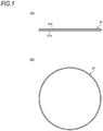
- Figs. 1(a) and 1(b) show a specific example of an appearance of a collection board 61 according to an embodiment of the present invention.
- Fig. 1(a) is a front view
- Fig. 1(b) is a plan view.
- the collection board 61 shown in Figs. 1(a) and 1(b) is formed in a thin disk shape.
- the collection board 61 includes a base material 61a and a thin film 61b formed on a surface of the base material 61a.
- aluminum is used as a material of the base material 61a.
- the thin film 61b is formed on the surface of the base material 61a by an electroless nickel-plating treatment.
- the material and a thickness of the base material 61a are determined such that the collection board 61 can secure a sufficient strength.
- a material of the thin film 61b a substance not contained in wear debris is selected such that the wear debris to be measured and the thin film 61b are easily distinguished from each other. Further, when the wear debris are observed using a scanning electron microscope (SEM), a substance that hardly influences an image of the wear debris during observation is selected as the material of the thin film 61b.
- SEM scanning electron microscope
- nickel is not contained in the wear debris, it is easy to distinguish between the thin film 61b on the collection board 61 and the wear debris when using the thin film 61b formed by the electroless nickel-plating treatment. Further, it has been confirmed that, for example, the nickel hardly influences observation of the wear debris when the wear debris are observed using the scanning electron microscope.
- the thickness of the thin film 61b is defined to be, for example, a thickness of 5 ⁇ m or more.
- a state of a surface of the thin film 61b if there is a scratch or the like, submicron-sized debris may enter an inside of the scratch and become difficult to observe. Therefore, it is desirable that the surface of the thin film 61b is mirror-polished to be smooth. That is, a surface roughness of the thin film 61b is defined so as to be at least equal to or smaller than a particle diameter of the wear debris to be observed.
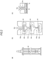
- Fig. 2(a) shows an example of an appearance of a classifier 62 that can be used for collecting the debris.
- Fig. 2(b) shows an enlarged view of a vertical cross section of a part of the classifier 62 in Fig. 2(a) .
- Fig. 2(c) shows a part of Fig. 2(b) .
- the classifier 62 shown in Figs. 2(a) to 2(c) is a known device called a low-pressure cascade impactor.
- the classifier 62 introduces an airflow containing debris generated by a brake device of an automobile or the like, and can classify and collect the debris for each size from the airflow.
- the special collection board 61 shown in Figs. 1(a) and 1(b) is used.
- the classifier 62 shown in Fig. 2(a) has a structure in which ten collection stages are stacked in a vertical direction and connected in series in a flow direction of an airflow. In an example shown in Fig. 2(b) , three collection stages are continuously arranged in an upper-lower direction. As shown in Fig. 2(b) , each collection stage of the classifier 62 includes a flow path of an airflow 62c including a nozzle 62a, and a collection portion 62b. Each collection portion 62b is disposed in a flat plate shape at a position facing an opening of the nozzle 62a. The collection board 61 is disposed at the collection portion 62b of each collection stage.
- diameters of the nozzles 62a of a plurality of collection stages of the classifier 62 are formed so as to gradually decrease from an upper stage side to a lower stage side. That is, the collection stage on an upper side is configured to be able to collect solid particles having a large particle diameter, and the collection stage on a lower side is configured to be able to collect solid particles having a small particle diameter.
- the airflow 62c passes through the nozzle 62a and flows toward the collection board 61 in front at a high speed. Then, particles such as debris 63 contained in the airflow 62c are collected by the collection board 61 due to an inertial collision. The airflow 62c other than the collected particles is further directed to a downstream side.
- Aluminum, glass fibers, or the like is used as a material of a general collection board used for the classifier 62. Further, in the electron microscope, a sample stage made of carbon is generally used.
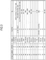
- Fig. 3 shows a list of substances not contained in the wear debris and materials that can be plated. That is, except for components that may be contained in a friction material used in a general brake device of an automobile or the like and wear debris generated by wear of a rotor, substances that can be plated are shown in Fig. 3 .
- the surface of the collection board 61 is formed by any substance of aluminum, chromium, cobalt, nickel, copper, zinc, ruthenium, rhodium, palladium, silver, cadmium, indium, tin, tungsten, iridium, platinum, and gold shown in Fig. 3 . Accordingly, when the debris 63 collected by the collection board 61 are observed with the scanning electron microscope or the like, the collection board 61 and the debris 63 can be distinguished from each other based on a difference between substances.
- the thin film 61b of the collection board 61 shown in Fig. 1(a) can be formed by the plating. Accordingly, when a strength required for the collection board 61 is sufficiently secured only by the base material 61a, a degree of freedom in selecting a substance of the thin film 61b is increased.
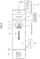
- Fig. 4 shows a configuration example of a system including a wear debris collection device.
- the system shown in Fig. 4 is configured such that, when a brake 11 used in an automobile or the like is operated, debris generated due to wear of a brake pad in a caliper 12 and a disc-shaped rotor 14 are collected, and components, shapes, sizes, and the like of the debris can be analyzed.
- the debris are actually analyzed, for example, it is assumed that the debris on the collection board 61 are observed using the scanning electron microscope not shown in Fig. 4 .
- the brake 11 shown in Fig. 4 is coupled to a brake test device 10 to be described later, and is held in a state where the rotor 14 can rotate and the caliper 12 can operate.
- the brake 11 is disposed in an inner space of a brake hood 50 as shown in Fig. 4 That is, a portion where the debris are generated and a portion where the generated debris are scattered are covered with the brake hood 50 in a state where an entire periphery thereof is sealed.
- a HEPA (high efficiency particulate air filter) filter 72 is disposed on a right side of the brake hood 50, and a blower 71 is further disposed on the right side of the brake hood 50.
- the blower 71 can send outside air into the inner space of the brake hood 50.
- An air blowing amount of the blower 71 is variable and is controlled by a control signal SG1.
- the HEPA filter 72 cleans air sent by the blower 71 by removing the dust and the like.
- an air sampler 60 is coupled to a tip end portion 50a of the brake hood 50.
- the air sampler 60 can suck an airflow 58 from a portion that communicates with the inner space of the brake hood 50, and can collect the floating debris contained in the airflow 58.
- the air sampler 60 has a suction capacity of, for example, about 500[liters/minute], and a suction flow rate is variable. When the air blowing amount of the blower 71 is controlled, the suction flow rate of the air sampler 60 may be fixed.
- a communication portion 55 is provided so as to be able to communicate with the inner space of the brake hood 50.
- the classifier 62 described above is connected to one end of the communication portion 55. Based on a principle of an aerodynamic diameter, the classifier 62 can individually collect and analyze the debris of each particle size such as less than 2.5 ⁇ m, 2.5 ⁇ m, and 10 ⁇ m by the collection board 61.
- a pressure sensor 73 is installed inside the brake hood 50.
- an installation position of the pressure sensor 73 is, for example, on an upstream side of the brake 11 with respect to a direction of the airflow 58 and above the brake 11, it is easy to prevent characteristics of the pressure sensor 73 from varying due to heat generation of the brake 11.
- a pressure sensor 74 is installed in a space outside the brake hood 50. Therefore, the pressure sensor 74 can detect an outside air pressure Pout. Further, the pressure sensor 73 can detect an inside air pressure Pin in the brake hood 50.
- a differential pressure gauge 75 outputs a differential pressure signal ⁇ P indicating a differential pressure between the inside air pressure Pin detected by the pressure sensor 73 and the outside air pressure Pout detected by the pressure sensor 74.
- a controller 80 generates a control signal SG1 based on the differential pressure signal ⁇ P output by the differential pressure gauge 75, and controls the blower 71 such that the differential pressure between the inside air pressure Pin and the outside air pressure Pout is eliminated. For example, when the controller 80 detects a state where the inside air pressure Pin is lower than the outside air pressure Pout by the differential pressure signal ⁇ P, the controller 80 adjusts the control signal SG1 so as to increase the air blowing amount per unit time of the blower 71.
- a pressure in the inner space of the brake hood 50 decreases due to suction of air by the air sampler 60, but the decrease can be compensated by a pressure of air supplied into the brake hood 50 by the blower 71, and the inside air pressure Pin can be controlled to be the same as the outside air pressure Pout by adjusting the air blowing amount.
- the controller 80 controls the air blowing amount of the blower 71 so as to eliminate the differential pressure between the inside air pressure Pin and the outside air pressure Pout
- the suction flow rate of the air sampler 60 may be controlled or both may be controlled.
- the controller 80 detects a state where the inside air pressure Pin is lower than the outside air pressure Pout by the differential pressure signal ⁇ P
- the controller 80 performs control to reduce the suction flow rate per unit time.
- the controller 80 detects a state where the inside air pressure Pin is higher than the outside air pressure Pout by the differential pressure signal ⁇ P
- the controller 80 performs control to increase the suction flow rate per unit time.
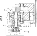
- Fig. 5 is a vertical cross-sectional view showing a configuration example of the brake test device including the wear debris collection device shown in Fig. 4 .
- a basic configuration of the brake test device 10 shown in Fig. 5 is the same as that of a known technique such as, for example, JP-A-H10-300597 , and further, the brake hood (cover) 50 that covers the brake 11 in order to collect the debris and a sealing structure for preventing inflow of the external dust from a gap are added.
- the brake test device 10 includes a low-speed rotation shaft 15 to which the rotor 14 of the brake 11 is attached, a high-speed rotation shaft 16 disposed parallel to the low-speed rotation shaft 15, and a flywheel 17 that is an inertial body attached to the high-speed rotation shaft 16. Further, the brake test device 10 includes a speed reduction unit 18 that reduces a rotational speed of the high-speed rotation shaft 16 and transmits the reduced rotational speed to the low-speed rotation shaft 15, a motor 19 that drives the high-speed rotation shaft 16, a base 13 that supports units, a control unit that controls the units, and a measurement unit that measures various pieces of data of the brake 11 (all of which are not shown).
- the low-speed rotation shaft 15 includes a first rotation shaft 21 and a second rotation shaft 23 coupled to each other by a universal joint 22.
- a circular plate portion 24 having a large diameter is provided at a left end of the second rotation shaft 23 in the drawing, and the rotor 14 is fitted to the circular plate portion 24.
- the low-speed rotation shaft 15 is supported by bearings 25 and 26 attached to the base 13. Further, a large gear 27 of the speed reduction unit 18 is attached to a portion between the bearings 25 and 26 of the low-speed rotation shaft 15.
- a sleeve 20 fixed to the base 13 is disposed on a left side portion of the low-speed rotation shaft 15.
- a housing 28 is attached to the sleeve 20 via a bearing.
- the caliper 12 of the brake 11 is attached to a flange portion 29 of the housing 28 via a plate 30.
- the high-speed rotation shaft 16 is supported by bearings 31, 32, and 33 attached to the base 13. Further, a small gear 34 is formed on a left side of a center of the high-speed rotation shaft 16 in the drawing.
- the large gear 27 attached to the low-speed rotation shaft 15 meshes with the small gear 34.
- the large gear 27 and the small gear 34 constitute the speed reduction unit 18.
- the flywheel 17 is attached to the high-speed rotation shaft 16, and the flywheel 17 is disposed in a concave portion 35 provided in the base 13. Further, a pulley 36 is fitted to a left end of the high-speed rotation shaft 16 in the drawing.
- the motor 19 is disposed in a concave groove 37 provided at a lower end of the base 13, and the pulley 38 is attached to a rotation shaft of the motor 19. Then, a belt 39 is wound around the pulley 36 of the high-speed rotation shaft 16 and the pulley 38 of the rotation shaft of the motor 19. Accordingly, the high-speed rotation shaft 16 is driven by the motor 19.
- the brake hood 50 is fixed to an outside of the housing (a caliper holding unit) 28 that does not rotate. Then, the brake hood 50 covers an entire outside of a brake attachment portion 10b including the caliper 12 and the rotor 14 of the brake 11, and houses the brake attachment portion 10b, the caliper 12, and the rotor 14 inside.
- Fig. 6 shows an outline of manufacturing steps of the collection board 61 shown in Figs. 1(a) and 1(b) . The manufacturing steps of Fig. 6 will be described below.
- a thin plate of aluminum is prepared as a material, and the base material 61a of the collection board 61 is formed.
- the board-shaped base material 61a having a diameter of 25[mm], a thickness of 0.55mm, and a flat surface shape is formed (S11).
- the base material 61a is subjected to the electroless nickel-plating treatment to form the nickel thin film 61b on a surface (S12).
- a film thickness of the thin film 61b is set to 5 ⁇ m or more. Since the film thickness is set to 5 ⁇ m or more, when the debris 63 are observed with the scanning electron microscope, it is possible to ignore appearance of an influence of aluminum of a skin covered by the thin film 61b, that is, the base material 61a.
- a surface of the collection board 61 on which the thin film 61b is formed is subjected to a surface polishing treatment to remove unevenness and scratches on the surface (S13).
- a roughness of the surface of the collection board 61 is made equal to or smaller than the particle diameter of the debris 63. Accordingly, the debris 63 are prevented from being buried in a scratch or a depression on the surface of the collection board 61, and a difference in a position of each particle of the debris 63 (a distance from an observation side to particles) is also eliminated, so that a particle shape and the like are easily grasped when the debris 63 are observed with the scanning electron microscope.
- Fig. 7 shows a procedure for measuring the wear debris. The procedure of Fig. 7 will be described below.
- the collection board 61 manufactured by the manufacturing step (S10) shown in Fig. 6 is prepared and installed at a predetermined position of the classifier 62 (S21). That is, the surface of the thin film 61b is disposed in the collection portion 62b of the collection stage capable of collecting the debris 63 having the particle diameter to be observed so as to face the opening of the nozzle 62a from which the airflow 62c is blown out, that is, disposed as shown in Fig. 2(c) .
- the brake test device 10 is operated to perform a test of the brake 11 (S22). Accordingly, an airflow containing the debris 63 generated by the brake 11 is introduced into an inflow port of the classifier 62 via the tip end portion 51a of the brake hood 50 and the communication portion 55. Therefore, the debris 63 are collected by the collection board 61.
- the collection board 61 that has collected the debris 63 is taken out from the classifier 62, for example, manually by an operator or by using a predetermined robot, and is disposed on the sample stage of the scanning electron microscope (not shown) (S23). Accordingly, it is possible to observe the debris 63 on the collection board 61 with the scanning electron microscope, to analyze the components of the debris 63, to identify shapes and sizes of the debris 63, and the like.
- Fig. 8 shows an example of an image when the debris collected using the collection board 61 of the embodiment of the present invention are observed with the scanning electron microscope. That is, the collected debris 63 and the surface of the collection board 61 that collects the debris 63 appear in the image of Fig. 8 .
- the image shown in Fig. 8 shows an example of a case where the debris 63 generated from the brake device are observed with the scanning electron microscope.
- the debris 63 having particle diameters of about 0.1 to several ⁇ m appear in a clearly distinguishable state. Therefore, it is possible to easily perform a measurement such as a component analysis of the debris 63, specification of a shape of each particle, and specification of a particle diameter.
- the debris 63 in each image and the thin film 61b in the background can be distinguished from each other. Further, since the thickness of the thin film 61b is sufficiently large, an influence of aluminum that constitutes the base material 61a of the skin does not appear in each image. Further, since the scratches, the unevenness, and the like on the surface of the thin film 61b are removed in advance by the mirror polishing, the debris 63 are not buried in the concave portion, and the distance from the observation side to the particles is the same, and thus the debris 63 clearly appear in the image.
- Figs. 9(a), 9(b), and 9(c) show examples of images when observing debris collected using a general collection board of a fluorine resin-treated glass fibers instead of the collection board 61 according to the present embodiment with the scanning electron microscope.
- Figs. 10(a), 10(b), and 10(c) show examples of images when observing debris collected using a general collection board configured with aluminum instead of the collection board 61 according to the present embodiment with the scanning electron microscope.
- the present invention there is an effect that it is possible to provide a dust measurement device and a dust measurement method capable of easily observing debris generated from a brake device.
- the present invention having this effect is useful for a dust measurement device and a dust measurement method for collecting and measuring dust from an aerosol containing the dust generated by a friction material that generates a braking force.
Landscapes
- Chemical & Material Sciences (AREA)
- Health & Medical Sciences (AREA)
- Life Sciences & Earth Sciences (AREA)
- General Physics & Mathematics (AREA)
- Pathology (AREA)
- Analytical Chemistry (AREA)
- Biochemistry (AREA)
- General Health & Medical Sciences (AREA)
- Physics & Mathematics (AREA)
- Immunology (AREA)
- Dispersion Chemistry (AREA)
- Engineering & Computer Science (AREA)
- Biomedical Technology (AREA)
- Molecular Biology (AREA)
- Signal Processing (AREA)
- Analysing Materials By The Use Of Radiation (AREA)
- Sampling And Sample Adjustment (AREA)
Abstract

Description
- The present invention relates to a dust measurement device and a dust measurement method for collecting and measuring dust from an aerosol containing the dust generated by a friction material that generates a braking force.
- For example, when a brake device such as a disk brake or a drum brake mounted on an automobile or the like operates, debris is generated due to wear between a brake pad and a rotor. Therefore, for example, an actual braking state, behavior, and wear states of members of the brake device are reflected in shapes, sizes, wear debris generation amounts, and the like of the debris.
- Therefore, when the materials, the shapes, the sizes, the wear debris generation amounts, and the like of the debris actually generated in the brake device are analyzed, the brake device can be improved and performance thereof can be improved.
- Patent Literature 1 discloses a technology for improving an device operation rate, productivity, and classification accuracy in an airflow classifier used in manufacturing a fine-particle toner, in which fusion is less likely to occur due to a collision of to-be-classified raw materials. Further, an airflow classifier in which a composite plating film in which fine particles are dispersed and contained is provided on a surface of a member in the airflow classifier in which particles of a to-be-classified raw material collide is shown. Further, the airflow classifier includes a raw
material sorting chamber 14 in which a plurality of classification exhaust flow paths 7, 8, and 9 branched by classification edges 2 and 3 are opened on an outlet side, andintake flow paths intake flow paths material supply nozzle 16 that pressure-feeds and injects a to-be-classifiedraw material 15 into the rawmaterial sorting chamber 14 by using a compressed gas. The following mode is shown. That is, particles of the to-be-classifiedraw material 15 pressure-fed and injected into the rawmaterial sorting chamber 14 are classified into the respective classification exhaust flow paths 7, 8, and 9 by a curved linear scattering and lowering action corresponding to particle diameters based on a Coanda effect. - A particle collection device of Patent Literature 2 discloses a technology for analyzing an evaluation of the number, a shape, components, and the like and enabling a use of a collision plate of an optional size even when dust is collected in a place where there is a little floating dust, such as in a clean room. Further, the particle collection device of Patent Literature 2 uses a clean mirror-finished collision plate.
-
- Patent Literature 1:
JP-A-H10-202192 - Patent Literature 2:
JP-A-S63-75639 - For example, particles such as dust collected by colliding with a collision plate as shown in Patent Literature 2 can be observed using, for example, a scanning electron microscope (SEM). That is, an observer can visually grasp shapes, sizes, materials, and the like of the particles from an image obtained by the scanning electron microscope.
- However, debris generated from a brake device are as small as about submicron and contain components of various materials. Therefore, it is actually difficult to observe the debris with the scanning electron microscope. Specifically, it may be difficult to distinguish an uneven shape on a surface of a collection board that collects the debris from the debris. Further, due to commonality of materials, outer shapes of materials of the debris and a boundary between the debris and the collection board, that is, an outline shape of the debris may become unclear. Further, when the surface of the collection board is subjected to a plating treatment, the shapes or the like of the debris may be difficult to visually recognize due to an influence of a skin material behind a coating film formed on the surface of the collection board.
- The present invention has been made in view of the above circumstances, and an object thereof is to provide a dust measurement device and a dust measurement method capable of easily observing debris generated from a brake device.
- In order to achieve the above object, a dust measurement device and a dust measurement method according to the present invention are characterized by the following (1) to (7).
- (1) A dust measurement device including:
- a collection board that is disposed at a position where an aerosol containing dust generated by a friction material collides with the collection board, wherein
- the dust measurement device is configured to measure the dust collected by the collection board based on an inertial force of the dust, and
- a first substance that constitutes at least a surface of the collection board is different from a material that constitutes a component contained in a second substance contained in the dust to be measured.
- (2) The dust measurement device according to the above (1),
in which the first substance contains any one material of nickel, chromium, and cobalt. - (3) The dust measurement device according to the above (1) or (2),
- in which the collection board includes a base material and a thin film formed on a surface portion of the base material, and
- in which the thin film is made of the first substance.
- (4) The dust measurement device according to the above (3), further including:
- a scanning electron microscope configured to observe the dust on the collection board,
- in which a thickness of the thin film has a dimension equal to or larger than a predetermined size required for reducing an influence of the base material on the dust in observation with the scanning electron microscope.
- (5) A dust measurement method for measuring dust generated by a friction material, the dust measurement method including:
- preparing a collection board in which at least a first substance that constitutes a surface with which the dust to be measured collides is different from a material that constitutes a component contained in a second substance contained in the dust;
- disposing the collection board at a position where a aerosol containing dust to be measured collides with the collection board;
- introducing a aerosol containing dust generated by a friction material configured to generate a braking force into a vicinity of the collection board; and
- collecting the dust by the collection board based on an inertial force of the dust.
- (6) The dust measurement method according to the above (5),
in which the first substance contains any one material of nickel, chromium, and cobalt. - (7) The dust measurement method according to the above (5) or (6),
- in which a thin film is formed on a surface portion of a base material to form the collection board, and
- in which the thin film is made of the first substance.
- According to the dust measurement device having the configuration of the above (1), since the material of the first substance and the material of the second substance are different from each other, these materials can be easily distinguished from each other, and the measurement of the dust to be measured can be performed with high accuracy. For example, when the surface of the collection board is observed as an image by using the scanning electron microscope, the surface of the collection board and dust attached thereto can be distinguished from each other by a difference in the materials, and a shape, a size, and the like of the dust can be clearly identified.
- According to the dust measurement device having the configuration of the above (2), the material that constitutes the first substance is different from a material that constitutes a friction material or a rotor of a general brake device, and therefore is easily distinguished from the component contained in the second substance contained in the dust to be measured. Further, it is easy to reduce a content of impurities in the material that constitutes the first substance, and it is also easy to distinguish the component contained in the second substance from the impurities.
- According to the dust measurement device having the configuration of the above (3), since the base material of the collection board is covered by the thin film (a film thickness that does not influence observation with an electron microscope), a degree of freedom of a material that constitutes the base material is increased. Therefore, since the thin film is formed of the material that constitutes the first substance while sufficiently securing a strength of the collection board with the base material, it is easy to distinguish the thin film from the component contained in the second substance contained in the dust to be measured.
- According to the dust measurement device having the configuration of the above (4), even when the material of the base material is the same as the component contained in the second substance contained in the dust to be measured, the dust can be observed with the scanning electron microscope without being influenced by the base material present on a back side of the thin film. Therefore, it is also easy to secure the strength of the collection board by the base material.
- According to the dust measurement method having the configuration of the above (5), since a material of the first substance and a material of the second substance are different from each other, when the surface of the collection board is observed as an image by using, for example, an scanning electron microscope, the surface of the collection board and dust attached thereto can be distinguished from each other by a difference in the materials, and a shape, a size, and the like of the dust can be clearly identified. Therefore, the dust can be measured with high accuracy.
- According to the dust measurement method having the configuration of the above (6), the material that constitutes the first substance is different from a material that constitutes a friction material or a rotor of a general brake device, and therefore is easily distinguished from the component contained in the second substance contained in the dust to be measured. Further, it is easy to reduce a content of impurities in the material that constitutes the first substance, and it is also easy to distinguish the component contained in the second substance from the impurities.
- According to the dust measurement method having the configuration of the above (7), since the base material of the collection board is covered by the thin film (a film thickness that does not influence observation with an electron microscope), a degree of freedom of a material that constitutes the base material is increased. Therefore, since the thin film is formed of the material that constitutes the first substance while sufficiently securing a strength of the collection board with the base material, it is easy to distinguish the thin film from the component contained in the second substance contained in the dust to be measured.
- According to a dust measurement device and a dust measurement method of the present invention, debris generated from a brake device are easily observed. That is, since a material of a first substance and a material of a second substance are different from each other, when a surface of a collection board is observed as an image by using a scanning electron microscope or the like, the surface of the collection board and dust attached thereto can be distinguished from each other by a difference in the materials, and a shape, a size, and the like of the dust can be clearly identified.
- The present invention has been briefly described above. Details of the present invention are further clarified by reading a mode for carrying out the invention (hereinafter, referred to as "embodiment") described below with reference to attached drawings.
-
- [
Fig. 1] Figs. 1(a) and 1(b) are specific examples of an appearance of a collection board according to an embodiment of the present invention.Fig. 1(a) is a front view andFig. 1(b) is a plan view. - [
Fig. 2] Fig. 2(a) is a front view showing an appearance of a classifier.Fig. 2(b) is a partially enlarged cross-sectional view showing a vertical cross section of a part of the classifier ofFig. 2(a). Fig. 2(c) is a partial cross-sectional view showing a part ofFig. 2(b) . - [
Fig. 3] Fig. 3 is a schematic diagram showing a list of substances not contained in wear debris. - [
Fig. 4] Fig. 4 is a block diagram showing a configuration example of a system including a wear debris collection device. - [
Fig. 5] Fig. 5 is a vertical cross-sectional view showing a configuration example of a brake attachment portion of a brake test device. - [
Fig. 6] Fig. 6 is a flowchart showing a manufacturing step of the collection board. - [
Fig. 7] Fig. 7 is a flowchart showing a procedure for measuring the wear debris. - [
Fig. 8] Fig. 8 is a front view showing an example of an image when observing, with a scanning electron microscope, debris collected using the collection board according to the embodiment of the present invention. - [
Fig. 9] Figs. 9(a), 9(b), and 9(c) are front views showing examples of images when observing, with the scanning electron microscope, debris collected using a collection board of fluorine resin-treated glass fibers, respectively. - [
Fig. 10] Figs. 10(a), 10(b), and 10(c) are front views showing examples of images when observing, with the scanning electron microscope, debris collected using a collection board configured with aluminum, respectively. - A specific embodiment according to the present invention will be described below with reference to the drawings.
-
Figs. 1(a) and 1(b) show a specific example of an appearance of acollection board 61 according to an embodiment of the present invention.Fig. 1(a) is a front view, andFig. 1(b) is a plan view. - The
collection board 61 shown inFigs. 1(a) and 1(b) is formed in a thin disk shape. Thecollection board 61 includes abase material 61a and athin film 61b formed on a surface of thebase material 61a. In the present embodiment, aluminum is used as a material of thebase material 61a. Further, thethin film 61b is formed on the surface of thebase material 61a by an electroless nickel-plating treatment. - The material and a thickness of the
base material 61a are determined such that thecollection board 61 can secure a sufficient strength. Regarding a material of thethin film 61b, a substance not contained in wear debris is selected such that the wear debris to be measured and thethin film 61b are easily distinguished from each other. Further, when the wear debris are observed using a scanning electron microscope (SEM), a substance that hardly influences an image of the wear debris during observation is selected as the material of thethin film 61b. - For example, since nickel is not contained in the wear debris, it is easy to distinguish between the
thin film 61b on thecollection board 61 and the wear debris when using thethin film 61b formed by the electroless nickel-plating treatment. Further, it has been confirmed that, for example, the nickel hardly influences observation of the wear debris when the wear debris are observed using the scanning electron microscope. - It is desirable to limit the thickness of the
thin film 61b such that an influence of the material of theunderlying base material 61a does not appear when the wear debris are observed using the scanning electron microscope, and it is preferable that the thickness of thethin film 61b is defined to be, for example, a thickness of 5µm or more. - Further, regarding a state of a surface of the
thin film 61b, if there is a scratch or the like, submicron-sized debris may enter an inside of the scratch and become difficult to observe. Therefore, it is desirable that the surface of thethin film 61b is mirror-polished to be smooth. That is, a surface roughness of thethin film 61b is defined so as to be at least equal to or smaller than a particle diameter of the wear debris to be observed. -
Fig. 2(a) shows an example of an appearance of aclassifier 62 that can be used for collecting the debris. Further,Fig. 2(b) shows an enlarged view of a vertical cross section of a part of theclassifier 62 inFig. 2(a) . Further,Fig. 2(c) shows a part ofFig. 2(b) . - The
classifier 62 shown inFigs. 2(a) to 2(c) is a known device called a low-pressure cascade impactor. Theclassifier 62 introduces an airflow containing debris generated by a brake device of an automobile or the like, and can classify and collect the debris for each size from the airflow. However, when components, shapes, sizes, and the like of the collected debris are observed with the scanning electron microscope or the like, there is a high possibility that component analysis or the like becomes difficult with a general collection board. Therefore, for example, thespecial collection board 61 shown inFigs. 1(a) and 1(b) is used. - The
classifier 62 shown inFig. 2(a) has a structure in which ten collection stages are stacked in a vertical direction and connected in series in a flow direction of an airflow. In an example shown inFig. 2(b) , three collection stages are continuously arranged in an upper-lower direction. As shown inFig. 2(b) , each collection stage of theclassifier 62 includes a flow path of anairflow 62c including anozzle 62a, and acollection portion 62b. Eachcollection portion 62b is disposed in a flat plate shape at a position facing an opening of thenozzle 62a. Thecollection board 61 is disposed at thecollection portion 62b of each collection stage. - As shown in
Fig. 2(b) , diameters of thenozzles 62a of a plurality of collection stages of theclassifier 62 are formed so as to gradually decrease from an upper stage side to a lower stage side. That is, the collection stage on an upper side is configured to be able to collect solid particles having a large particle diameter, and the collection stage on a lower side is configured to be able to collect solid particles having a small particle diameter. - As shown in
Fig. 2(c) , at each collection stage, theairflow 62c passes through thenozzle 62a and flows toward thecollection board 61 in front at a high speed. Then, particles such asdebris 63 contained in theairflow 62c are collected by thecollection board 61 due to an inertial collision. Theairflow 62c other than the collected particles is further directed to a downstream side. - Aluminum, glass fibers, or the like is used as a material of a general collection board used for the
classifier 62. Further, in the electron microscope, a sample stage made of carbon is generally used. -
Fig. 3 shows a list of substances not contained in the wear debris and materials that can be plated. That is, except for components that may be contained in a friction material used in a general brake device of an automobile or the like and wear debris generated by wear of a rotor, substances that can be plated are shown inFig. 3 . - That is, it is assumed that at least the surface of the
collection board 61 is formed by any substance of aluminum, chromium, cobalt, nickel, copper, zinc, ruthenium, rhodium, palladium, silver, cadmium, indium, tin, tungsten, iridium, platinum, and gold shown inFig. 3 . Accordingly, when thedebris 63 collected by thecollection board 61 are observed with the scanning electron microscope or the like, thecollection board 61 and thedebris 63 can be distinguished from each other based on a difference between substances. - Since any of the substances shown in
Fig. 3 can be subjected to a plating treatment, thethin film 61b of thecollection board 61 shown inFig. 1(a) can be formed by the plating. Accordingly, when a strength required for thecollection board 61 is sufficiently secured only by thebase material 61a, a degree of freedom in selecting a substance of thethin film 61b is increased. -
Fig. 4 shows a configuration example of a system including a wear debris collection device. The system shown inFig. 4 is configured such that, when abrake 11 used in an automobile or the like is operated, debris generated due to wear of a brake pad in acaliper 12 and a disc-shapedrotor 14 are collected, and components, shapes, sizes, and the like of the debris can be analyzed. When the debris are actually analyzed, for example, it is assumed that the debris on thecollection board 61 are observed using the scanning electron microscope not shown inFig. 4 . - The
brake 11 shown inFig. 4 is coupled to abrake test device 10 to be described later, and is held in a state where therotor 14 can rotate and thecaliper 12 can operate. Thebrake 11 is disposed in an inner space of abrake hood 50 as shown inFig. 4 That is, a portion where the debris are generated and a portion where the generated debris are scattered are covered with thebrake hood 50 in a state where an entire periphery thereof is sealed. - Accordingly, dust and the like outside the
brake hood 50 can also be prevented from entering an inside of thebrake hood 50. However, when thebrake 11 is tested, since it is necessary to connect a rotating portion such as a shaft between the inside and an outside of thebrake hood 50, it is difficult to completely eliminate a gap that allows the inside and the outside of thebrake hood 50 to communicate with each other even when sealing is performed. Therefore, pressure control to be described later is performed such that the debris and the dust do not pass through the gap. By the pressure control, it is possible to prevent the dust and the like from an outside other than the debris from being mixed into the debris. - As shown in
Fig. 4 , a HEPA (high efficiency particulate air filter)filter 72 is disposed on a right side of thebrake hood 50, and ablower 71 is further disposed on the right side of thebrake hood 50. Theblower 71 can send outside air into the inner space of thebrake hood 50. An air blowing amount of theblower 71 is variable and is controlled by a control signal SG1. TheHEPA filter 72 cleans air sent by theblower 71 by removing the dust and the like. - On the other hand, an
air sampler 60 is coupled to atip end portion 50a of thebrake hood 50. Theair sampler 60 can suck anairflow 58 from a portion that communicates with the inner space of thebrake hood 50, and can collect the floating debris contained in theairflow 58. Theair sampler 60 has a suction capacity of, for example, about 500[liters/minute], and a suction flow rate is variable. When the air blowing amount of theblower 71 is controlled, the suction flow rate of theair sampler 60 may be fixed. - A
communication portion 55 is provided so as to be able to communicate with the inner space of thebrake hood 50. Theclassifier 62 described above is connected to one end of thecommunication portion 55. Based on a principle of an aerodynamic diameter, theclassifier 62 can individually collect and analyze the debris of each particle size such as less than 2.5 µm, 2.5 µm, and 10 µm by thecollection board 61. - As shown in
Fig. 4 , apressure sensor 73 is installed inside thebrake hood 50. When an installation position of thepressure sensor 73 is, for example, on an upstream side of thebrake 11 with respect to a direction of theairflow 58 and above thebrake 11, it is easy to prevent characteristics of thepressure sensor 73 from varying due to heat generation of thebrake 11. On the other hand, apressure sensor 74 is installed in a space outside thebrake hood 50. Therefore, thepressure sensor 74 can detect an outside air pressure Pout. Further, thepressure sensor 73 can detect an inside air pressure Pin in thebrake hood 50. Adifferential pressure gauge 75 outputs a differential pressure signal ΔP indicating a differential pressure between the inside air pressure Pin detected by thepressure sensor 73 and the outside air pressure Pout detected by thepressure sensor 74. - A
controller 80 generates a control signal SG1 based on the differential pressure signal ΔP output by thedifferential pressure gauge 75, and controls theblower 71 such that the differential pressure between the inside air pressure Pin and the outside air pressure Pout is eliminated. For example, when thecontroller 80 detects a state where the inside air pressure Pin is lower than the outside air pressure Pout by the differential pressure signal ΔP, thecontroller 80 adjusts the control signal SG1 so as to increase the air blowing amount per unit time of theblower 71. That is, a pressure in the inner space of thebrake hood 50 decreases due to suction of air by theair sampler 60, but the decrease can be compensated by a pressure of air supplied into thebrake hood 50 by theblower 71, and the inside air pressure Pin can be controlled to be the same as the outside air pressure Pout by adjusting the air blowing amount. - In the system shown in
Fig. 1 , although thecontroller 80 controls the air blowing amount of theblower 71 so as to eliminate the differential pressure between the inside air pressure Pin and the outside air pressure Pout, the suction flow rate of theair sampler 60 may be controlled or both may be controlled. In a case of controlling the suction flow rate of theair sampler 60, when thecontroller 80 detects a state where the inside air pressure Pin is lower than the outside air pressure Pout by the differential pressure signal ΔP, thecontroller 80 performs control to reduce the suction flow rate per unit time. Further, when thecontroller 80 detects a state where the inside air pressure Pin is higher than the outside air pressure Pout by the differential pressure signal ΔP, thecontroller 80 performs control to increase the suction flow rate per unit time. - When the differential pressure is controlled as described above, since the differential pressure between the inside air pressure Pin and the outside air pressure Pout is eliminated, a flow of air due to the differential pressure does not occur. That is, even when there is the gap that allows the inside and the outside of the
brake hood 50 to communicate with each other, since there is no flow of air that passes through the gap, debris that float in air in thebrake hood 50 do not leak to the outside from the gap. At the same time, the dust and the like outside thebrake hood 50 also do not enter the inside from the gap. As a result, the dust is prevented from being mixed into the collected debris. -
Fig. 5 is a vertical cross-sectional view showing a configuration example of the brake test device including the wear debris collection device shown inFig. 4 . A basic configuration of thebrake test device 10 shown inFig. 5 is the same as that of a known technique such as, for example,JP-A-H10-300597 brake 11 in order to collect the debris and a sealing structure for preventing inflow of the external dust from a gap are added. - The
brake test device 10 includes a low-speed rotation shaft 15 to which therotor 14 of thebrake 11 is attached, a high-speed rotation shaft 16 disposed parallel to the low-speed rotation shaft 15, and aflywheel 17 that is an inertial body attached to the high-speed rotation shaft 16. Further, thebrake test device 10 includes aspeed reduction unit 18 that reduces a rotational speed of the high-speed rotation shaft 16 and transmits the reduced rotational speed to the low-speed rotation shaft 15, amotor 19 that drives the high-speed rotation shaft 16, a base 13 that supports units, a control unit that controls the units, and a measurement unit that measures various pieces of data of the brake 11 (all of which are not shown). - The low-
speed rotation shaft 15 includes afirst rotation shaft 21 and asecond rotation shaft 23 coupled to each other by auniversal joint 22. Acircular plate portion 24 having a large diameter is provided at a left end of thesecond rotation shaft 23 in the drawing, and therotor 14 is fitted to thecircular plate portion 24. The low-speed rotation shaft 15 is supported bybearings base 13. Further, alarge gear 27 of thespeed reduction unit 18 is attached to a portion between thebearings speed rotation shaft 15. - A
sleeve 20 fixed to thebase 13 is disposed on a left side portion of the low-speed rotation shaft 15. Ahousing 28 is attached to thesleeve 20 via a bearing. Then, thecaliper 12 of thebrake 11 is attached to aflange portion 29 of thehousing 28 via aplate 30. - The high-
speed rotation shaft 16 is supported bybearings base 13. Further, asmall gear 34 is formed on a left side of a center of the high-speed rotation shaft 16 in the drawing. Thelarge gear 27 attached to the low-speed rotation shaft 15 meshes with thesmall gear 34. Thelarge gear 27 and thesmall gear 34 constitute thespeed reduction unit 18. Theflywheel 17 is attached to the high-speed rotation shaft 16, and theflywheel 17 is disposed in a concave portion 35 provided in thebase 13. Further, apulley 36 is fitted to a left end of the high-speed rotation shaft 16 in the drawing. - On the other hand, the
motor 19 is disposed in aconcave groove 37 provided at a lower end of thebase 13, and thepulley 38 is attached to a rotation shaft of themotor 19. Then, abelt 39 is wound around thepulley 36 of the high-speed rotation shaft 16 and thepulley 38 of the rotation shaft of themotor 19. Accordingly, the high-speed rotation shaft 16 is driven by themotor 19. - In the configuration shown in
Fig. 5 , it is assumed that thespeed reduction unit 18 is used, but thespeed reduction unit 18 may be omitted and a driving force of themotor 19 may be directly transmitted to thefirst rotation shaft 21. However, since it is necessary to generate an inertial force that simulates a weight of a vehicle on which thebrake 11 is mounted, theflywheel 17 is necessary. - In the
brake test device 10 shown inFig. 5 , when the high-speed rotation shaft 16 is driven by themotor 19, a rotational force of the high-speed rotation shaft 16 is transmitted to the low-speed rotation shaft 15 via thespeed reduction unit 18. When the low-speed rotation shaft 15 rotates, therotor 14 attached to the low-speed rotation shaft 15 rotates. In this state,friction materials 40 in thecaliper 12 are pressed against therotor 14. At this time, brake characteristics of thebrake 11 can be determined by measuring distortion of the low-speed rotation shaft 15 and other various pieces of data thereof. - In the
brake test device 10 shown inFig. 5 , thebrake hood 50 is fixed to an outside of the housing (a caliper holding unit) 28 that does not rotate. Then, thebrake hood 50 covers an entire outside of abrake attachment portion 10b including thecaliper 12 and therotor 14 of thebrake 11, and houses thebrake attachment portion 10b, thecaliper 12, and therotor 14 inside. - When the
friction materials 40 in thecaliper 12 are pressed against therotor 14, pressing surfaces of therotor 14 and thefriction materials 40 are worn by a frictional force. Further, therotor 14 and thefriction materials 40 respectively generate debris due to the wear, and a part of these debris floats in air. Therefore, it is possible to collect and measure the generated debris in the air. -
Fig. 6 shows an outline of manufacturing steps of thecollection board 61 shown inFigs. 1(a) and 1(b) . The manufacturing steps ofFig. 6 will be described below. - A thin plate of aluminum is prepared as a material, and the
base material 61a of thecollection board 61 is formed. For example, the board-shapedbase material 61a having a diameter of 25[mm], a thickness of 0.55mm, and a flat surface shape is formed (S11). - The
base material 61a is subjected to the electroless nickel-plating treatment to form the nickelthin film 61b on a surface (S12). A film thickness of thethin film 61b is set to 5µm or more. Since the film thickness is set to 5µm or more, when thedebris 63 are observed with the scanning electron microscope, it is possible to ignore appearance of an influence of aluminum of a skin covered by thethin film 61b, that is, thebase material 61a. - A surface of the
collection board 61 on which thethin film 61b is formed is subjected to a surface polishing treatment to remove unevenness and scratches on the surface (S13). By the polishing, a roughness of the surface of thecollection board 61 is made equal to or smaller than the particle diameter of thedebris 63. Accordingly, thedebris 63 are prevented from being buried in a scratch or a depression on the surface of thecollection board 61, and a difference in a position of each particle of the debris 63 (a distance from an observation side to particles) is also eliminated, so that a particle shape and the like are easily grasped when thedebris 63 are observed with the scanning electron microscope. -
Fig. 7 shows a procedure for measuring the wear debris. The procedure ofFig. 7 will be described below. - The
collection board 61 manufactured by the manufacturing step (S10) shown inFig. 6 is prepared and installed at a predetermined position of the classifier 62 (S21). That is, the surface of thethin film 61b is disposed in thecollection portion 62b of the collection stage capable of collecting thedebris 63 having the particle diameter to be observed so as to face the opening of thenozzle 62a from which theairflow 62c is blown out, that is, disposed as shown inFig. 2(c) . - In a state where the
classifier 62 in which thecollection boards 61 are installed is connected to thebrake test device 10 shown inFigs. 4 and5 according to the above procedure, thebrake test device 10 is operated to perform a test of the brake 11 (S22). Accordingly, an airflow containing thedebris 63 generated by thebrake 11 is introduced into an inflow port of theclassifier 62 via the tip end portion 51a of thebrake hood 50 and thecommunication portion 55. Therefore, thedebris 63 are collected by thecollection board 61. - After an end of the test of the
brake 11, thecollection board 61 that has collected thedebris 63 is taken out from theclassifier 62, for example, manually by an operator or by using a predetermined robot, and is disposed on the sample stage of the scanning electron microscope (not shown) (S23). Accordingly, it is possible to observe thedebris 63 on thecollection board 61 with the scanning electron microscope, to analyze the components of thedebris 63, to identify shapes and sizes of thedebris 63, and the like. -
Fig. 8 shows an example of an image when the debris collected using thecollection board 61 of the embodiment of the present invention are observed with the scanning electron microscope. That is, the collecteddebris 63 and the surface of thecollection board 61 that collects thedebris 63 appear in the image ofFig. 8 . - The image shown in
Fig. 8 shows an example of a case where thedebris 63 generated from the brake device are observed with the scanning electron microscope. - In the image of
Fig. 8 , thedebris 63 having particle diameters of about 0.1 to several µm appear in a clearly distinguishable state. Therefore, it is possible to easily perform a measurement such as a component analysis of thedebris 63, specification of a shape of each particle, and specification of a particle diameter. - That is, in the image of
Fig. 8 , since the substance that constitutes thethin film 61b existing in a background of thedebris 63 is clearly different from that of thedebris 63, thedebris 63 in each image and thethin film 61b in the background can be distinguished from each other. Further, since the thickness of thethin film 61b is sufficiently large, an influence of aluminum that constitutes thebase material 61a of the skin does not appear in each image. Further, since the scratches, the unevenness, and the like on the surface of thethin film 61b are removed in advance by the mirror polishing, thedebris 63 are not buried in the concave portion, and the distance from the observation side to the particles is the same, and thus thedebris 63 clearly appear in the image. -
Figs. 9(a), 9(b), and 9(c) show examples of images when observing debris collected using a general collection board of a fluorine resin-treated glass fibers instead of thecollection board 61 according to the present embodiment with the scanning electron microscope. - As shown in
Figs. 9(a) to 9(c) , although it is confirmed from the images that nano-sized particles considered to be the collecteddebris 63 are contained, shapes of particles are unclear and the particles are buried in a large number of fibers, which makes analysis difficult. -
Figs. 10(a), 10(b), and 10(c) show examples of images when observing debris collected using a general collection board configured with aluminum instead of thecollection board 61 according to the present embodiment with the scanning electron microscope. - As shown in
Figs. 10(a) to 10(c) , although it is confirmed from the images that nano-sized particles considered to be the collecteddebris 63 are contained, an analysis is difficult because the entire images containing the particles appear in a state of being covered with something. - That is, when the
debris 63 collected by a general collection board are measured using the scanning electron microscope, images as shown inFigs. 9(a) to 9(c) orFigs. 10(a) to 10(c) are obtained, so that it is difficult to analyze the components of thedebris 63 and grasp shapes, sizes, and the like of thedebris 63. However, by using thespecial collection board 61 as shown inFigs. 1(a) and 1(b) , it is easy to measure thedebris 63 for each particle as in the image shown inFig. 8 . - Here, characteristics of a dust measurement device and a dust measurement method according to the embodiment of the present invention described above will be briefly summarized and listed in the following [1] to [7].
- [1] A dust measurement device including:
- a collection board that is disposed at a position where an aerosol containing dust generated by a friction material collides with the collection board, wherein
- the debris measurement device is configured to measure the dust collected by the collection board based on an inertial force of the dust, and
- a first substance (a
thin film 61b) that constitutes at least a surface of the collection board (61) is different from a material that constitutes a component contained in a second substance contained in the dust (debris 63) to be measured.
- [2] The dust measurement device according to the above [1], in which the first substance contains any one material of nickel, chromium, and cobalt.
- [3] The dust measurement device according to the above [1] or [2],
- in which the collection board includes a base material (61a) and a thin film (61b) formed on a surface portion of the base material, and
- in which the thin film is configured with the first substance.
- [4] The dust measurement device according to the above [3], further including:
- a scanning electron microscope configured to observe the dust on the collection board,
- in which a thickness of the thin film has a dimension equal to or larger than a predetermined size required for reducing an influence of the base material on the dust in observation with the scanning electron microscope.
- [5] A dust measurement method for measuring dust generated by a friction material, the dust measurement method including:
- preparing a collection board (61) in which at least a first substance that constitutes a surface with which the dust to be measured collides is different from a material that constitutes a component contained in a second substance contained in the dust (S10);
- disposing the collection board at a position where a gas (an
airflow 62c) containing dust to be measured collides with the collection board (S21); - introducing an aerosol containing dust generated by a friction material configured to generate a braking force into a vicinity of the collection board (S22); and
- collecting the dust by the collection board based on an inertial force of the dust (S23).
- [6] The dust measurement method according to the above [5],
in which the first substance contains any one material of nickel, chromium, and cobalt. - [7] The dust measurement method according to the above [5] or [6],
- in which a thin film (61b) is formed on a surface portion of a base material (61a) to form the collection board, and
- in which the thin film is configured with the first substance.
- Although the present invention has been described in detail with reference to specific embodiments, it will be apparent to those skilled in the art that various changes and modifications can be made without departing from the spirit and scope of the present invention.
- The present application is based on Japanese Patent Application (
Japanese Patent Application No. 2018-190111) filed on Oct. 5, 2018 - According to the present invention, there is an effect that it is possible to provide a dust measurement device and a dust measurement method capable of easily observing debris generated from a brake device. The present invention having this effect is useful for a dust measurement device and a dust measurement method for collecting and measuring dust from an aerosol containing the dust generated by a friction material that generates a braking force.
-
- 10
- brake test device
- 10a
- tester main body
- 10b
- brake attachment portion
- 11
- brake
- 12
- caliper
- 13
- base
- 14
- rotor
- 15
- low-speed rotation shaft
- 16
- high-speed rotation shaft
- 17
- flywheel
- 18
- speed reduction unit
- 19
- motor
- 20
- sleeve
- 21
- first rotation shaft
- 22
- universal joint
- 23
- second rotation shaft
- 24
- circular plate portion
- 25,26
- bearing
- 27
- large gear
- 28
- housing (caliper holding unit)
- 31, 32, 33
- bearing
- 34
- small gear
- 36,38
- pulley
- 37
- concave groove
- 39
- belt
- 40
- friction material
- 50
- brake hood
- 55
- communication portion
- 58
- airflow
- 60
- air sampler
- 61
- collection board
- 61a
- base material
- 61b
- thin film
- 62
- classifier
- 62a
- nozzle
- 62b
- collection portion
- 62c
- airflow
- 63
- wear debris
- 71
- blower
- 72
- HEPA filter
- 73, 74
- pressure sensor
- 75
- differential pressure gauge
- 80
- controller
- SG1
- control signal
- Pin
- inside air pressure
- Pout
- outside air pressure
- ΔP
- differential pressure signal
Claims (7)
- A dust measurement device comprising:a collection board that is disposed at a position where an aerosol containing dust generated by a friction material collides with the collection board, whereinthe debris measurement device is configured to measure the dust collected by the collection board based on an inertial force of the dust, anda first substance that constitutes at least a surface of the collection board is different from a material that constitutes a component contained in a second substance contained in the dust to be measured.
- The dust measurement device according to claim 1, wherein
the first substance contains any one material of nickel, chromium, and cobalt. - The dust measurement device according to claim 1 or 2, whereinthe collection board includes a base material and a thin film formed on a surface portion of the base material, andthe thin film is made of the first substance.
- The dust measurement device according to claim 3, further comprising:a scanning electron microscope configured to observe the dust on the collection board,wherein a thickness of the thin film has a dimension equal to or larger than a predetermined size required for reducing an influence of the base material on the dust in observation with the scanning electron microscope.
- A dust measurement method for measuring dust generated by a friction material, the dust measurement method comprising:preparing a collection board in which at least a first substance that constitutes a surface with which the dust to be measured collides is different from a material that constitutes a component contained in a second substance contained in the dust;disposing the collection board at a position where an aerosol containing dust to be measured collides with the collection board;introducing an aerosol containing dust generated by a friction material configured to generate a braking force into a vicinity of the collection board; andcollecting the dust by the collection board based on an inertial force of the dust.
- The dust measurement method according to claim 5, wherein
the first substance contains any one material of nickel, chromium, and cobalt. - The dust measurement method according to claim 5 or 6, whereina thin film is formed on a surface portion of a base material to form the collection board, andthe thin film is made of the first substance.
Applications Claiming Priority (2)
| Application Number | Priority Date | Filing Date | Title |
|---|---|---|---|
| JP2018190111A JP7182125B2 (en) | 2018-10-05 | 2018-10-05 | Dust measuring device and dust measuring method |
| PCT/JP2019/039202 WO2020071510A1 (en) | 2018-10-05 | 2019-10-03 | Dust measurement device and dust measurement method |
Publications (2)
| Publication Number | Publication Date |
|---|---|
| EP3862744A1 true EP3862744A1 (en) | 2021-08-11 |
| EP3862744A4 EP3862744A4 (en) | 2022-08-03 |
Family
ID=70055676
Family Applications (1)
| Application Number | Title | Priority Date | Filing Date |
|---|---|---|---|
| EP19869029.9A Pending EP3862744A4 (en) | 2018-10-05 | 2019-10-03 | Dust measurement device and dust measurement method |
Country Status (3)
| Country | Link |
|---|---|
| EP (1) | EP3862744A4 (en) |
| JP (1) | JP7182125B2 (en) |
| WO (1) | WO2020071510A1 (en) |
Families Citing this family (4)
| Publication number | Priority date | Publication date | Assignee | Title |
|---|---|---|---|---|
| JP7723685B2 (en) * | 2020-12-14 | 2025-08-14 | 株式会社堀場製作所 | Brake dust measuring device and brake dust measuring method |
| CN114311162A (en) * | 2021-11-24 | 2022-04-12 | 重庆祥格家居有限公司 | Door plant cutting device |
| CN121336097A (en) * | 2023-06-23 | 2026-01-13 | 公益财团法人铁道综合技术研究所 | The collection device, measurement system, collection method, and measurement method for particulate matter. |
| JP2026027925A (en) * | 2024-08-06 | 2026-02-19 | 株式会社ブリヂストン | Wear debris collection device and wear debris collection method |
Family Cites Families (16)
| Publication number | Priority date | Publication date | Assignee | Title |
|---|---|---|---|---|
| US4570494A (en) * | 1984-04-11 | 1986-02-18 | The United States Of America As Represented By The United States Department Of Energy | Apparatus for sampling and characterizing aerosols |
| US4590792A (en) * | 1984-11-05 | 1986-05-27 | Chiang William W | Microanalysis particle sampler |
| JPS6375639A (en) | 1986-09-19 | 1988-04-06 | Hitachi Ltd | particle collection device |
| US5162053A (en) * | 1987-09-24 | 1992-11-10 | Kowalski Jr Walter J | Vehicular brake material collection system |
| JPH0221345U (en) * | 1988-07-27 | 1990-02-13 | ||
| JP3248443B2 (en) | 1997-01-21 | 2002-01-21 | 富士ゼロックス株式会社 | Airflow classifier and method for producing toner for developing electrostatic images |
| JP3724528B2 (en) | 1997-04-28 | 2005-12-07 | 曙ブレーキ工業株式会社 | Brake test equipment |
| JPH11311272A (en) * | 1998-04-30 | 1999-11-09 | Hitachi Chem Co Ltd | Disc brake pad |
| JP5700594B2 (en) * | 2011-02-22 | 2015-04-15 | 株式会社日立製作所 | Air microbe collection device and method |
| JP2015025713A (en) | 2013-07-25 | 2015-02-05 | 株式会社アドヴィックス | Frictional wear phenomenon analysis device of friction member |
| US9885640B2 (en) * | 2014-03-14 | 2018-02-06 | Particle Measuring Systems, Inc. | Particle impactor with selective height adjustment |
| GB2548652A (en) | 2014-04-18 | 2017-09-27 | Horiba Ltd | Sample dispersion device and sample dispersion method |
| JP2016100316A (en) | 2014-11-26 | 2016-05-30 | 住友金属鉱山株式会社 | Sample stage |
| JP6522133B2 (en) | 2015-08-21 | 2019-05-29 | 株式会社日立ハイテクノロジーズ | Observation support unit, sample observation method using the same, charged particle beam apparatus |
| WO2017097901A1 (en) * | 2015-12-09 | 2017-06-15 | Horiba Europe Gmbh | Apparatus for detecting and measuring brake dust |
| JP6863057B2 (en) | 2017-04-28 | 2021-04-21 | 横河電機株式会社 | Calibration work support device, calibration work support method, calibration work support program and recording medium |
-
2018
- 2018-10-05 JP JP2018190111A patent/JP7182125B2/en active Active
-
2019
- 2019-10-03 WO PCT/JP2019/039202 patent/WO2020071510A1/en not_active Ceased
- 2019-10-03 EP EP19869029.9A patent/EP3862744A4/en active Pending
Also Published As
| Publication number | Publication date |
|---|---|
| EP3862744A4 (en) | 2022-08-03 |
| JP7182125B2 (en) | 2022-12-02 |
| JP2020060386A (en) | 2020-04-16 |
| WO2020071510A1 (en) | 2020-04-09 |
Similar Documents
| Publication | Publication Date | Title |
|---|---|---|
| JP7182125B2 (en) | Dust measuring device and dust measuring method | |
| JP6720423B2 (en) | Device for detecting and measuring brake dust | |
| EP3783332B1 (en) | Abrasive powder collection device, analysis system, abrasive powder collection method, and analysis method | |
| CA2369802C (en) | Particle quantifying apparatus and method | |
| JP3658126B2 (en) | Air filter test method and test apparatus used therefor | |
| US8012239B2 (en) | Method and apparatus for detecting leaks in bashouse bags | |
| JPS61173132A (en) | Particle sampler device for microanalysis and its usage method | |
| EP1124126A2 (en) | Barrier test apparatus and method | |
| Jackiewicz et al. | Analysis of the behavior of deposits in fibrous filters during non-steady state filtration using X-ray computed tomography | |
| CN107407625B (en) | Device for measuring exposure to small particles, especially nanotubes | |
| Wahlström et al. | A disc brake test stand for measurement of airborne wear particles | |
| CN101027553A (en) | System and method for characterising grinding material in a roller mill | |
| KR20120016016A (en) | Filter health monitoring system | |
| US5954845A (en) | Apparatus for sampling aerosols | |
| KR100464161B1 (en) | A Respirable Aerosol Sampler | |
| JP2001289769A (en) | Dust collection / counting device | |
| Maus et al. | Determination of the fractional efficiencies of fibrous filter media by optical in situ measurements | |
| Tatum et al. | Performance of the RespiCon™ personal aerosol sampler in forest products industry workplaces | |
| Abdel-Salam | Aerosol sampling methods in workplace and ambient environments | |
| JPH10318908A (en) | Pollen monitor | |
| JPS6375639A (en) | particle collection device | |
| CN112845372B (en) | Apparatus and method for suppressing optical element defect | |
| JP2019143990A (en) | Maintenance device | |
| CN117606738B (en) | Device and method for measuring the dust purification coefficient of cutting materials | |
| CN224262561U (en) | Inspecting and alarming equipment in confined spaces |
Legal Events
| Date | Code | Title | Description |
|---|---|---|---|
| STAA | Information on the status of an ep patent application or granted ep patent |
Free format text: STATUS: THE INTERNATIONAL PUBLICATION HAS BEEN MADE |
|
| PUAI | Public reference made under article 153(3) epc to a published international application that has entered the european phase |
Free format text: ORIGINAL CODE: 0009012 |
|
| STAA | Information on the status of an ep patent application or granted ep patent |
Free format text: STATUS: REQUEST FOR EXAMINATION WAS MADE |
|
| 17P | Request for examination filed |
Effective date: 20210401 |
|
| AK | Designated contracting states |
Kind code of ref document: A1 Designated state(s): AL AT BE BG CH CY CZ DE DK EE ES FI FR GB GR HR HU IE IS IT LI LT LU LV MC MK MT NL NO PL PT RO RS SE SI SK SM TR |
|
| DAV | Request for validation of the european patent (deleted) | ||
| DAX | Request for extension of the european patent (deleted) | ||
| RIN1 | Information on inventor provided before grant (corrected) |
Inventor name: UENO, ATSUSHI Inventor name: SUZUKI, SHIGETOMO Inventor name: YAMAZAKI, YASUKO Inventor name: MATSUDA, TARO Inventor name: NAKAGAWA, HIDEHIKO |
|
| A4 | Supplementary search report drawn up and despatched |
Effective date: 20220630 |
|
| RIC1 | Information provided on ipc code assigned before grant |
Ipc: G01N 15/14 20060101ALI20220624BHEP Ipc: G01N 15/02 20060101ALI20220624BHEP Ipc: G01N 1/22 20060101ALI20220624BHEP Ipc: G01N 23/2251 20180101ALI20220624BHEP Ipc: G01N 15/00 20060101ALI20220624BHEP Ipc: G01N 1/02 20060101ALI20220624BHEP Ipc: G01N 15/10 20060101AFI20220624BHEP |
|
| STAA | Information on the status of an ep patent application or granted ep patent |
Free format text: STATUS: EXAMINATION IS IN PROGRESS |
|
| 17Q | First examination report despatched |
Effective date: 20240717 |