EP3862546A1 - Exhaust manifold heat dissipation cover coupling device for thermal stress and vibration deflection - Google Patents
Exhaust manifold heat dissipation cover coupling device for thermal stress and vibration deflection Download PDFInfo
- Publication number
- EP3862546A1 EP3862546A1 EP21155441.5A EP21155441A EP3862546A1 EP 3862546 A1 EP3862546 A1 EP 3862546A1 EP 21155441 A EP21155441 A EP 21155441A EP 3862546 A1 EP3862546 A1 EP 3862546A1
- Authority
- EP
- European Patent Office
- Prior art keywords
- bush
- heat dissipation
- dissipation cover
- elastic body
- exhaust manifold
- Prior art date
- Legal status (The legal status is an assumption and is not a legal conclusion. Google has not performed a legal analysis and makes no representation as to the accuracy of the status listed.)
- Granted
Links
- 230000017525 heat dissipation Effects 0.000 title claims abstract description 103
- 230000008878 coupling Effects 0.000 title claims abstract description 47
- 238000010168 coupling process Methods 0.000 title claims abstract description 47
- 238000005859 coupling reaction Methods 0.000 title claims abstract description 47
- 230000008646 thermal stress Effects 0.000 title claims abstract description 27
- 239000000463 material Substances 0.000 claims description 4
- 230000006378 damage Effects 0.000 abstract description 11
- 230000008602 contraction Effects 0.000 abstract description 6
- 230000010485 coping Effects 0.000 abstract description 4
- 230000003685 thermal hair damage Effects 0.000 description 3
- 230000000903 blocking effect Effects 0.000 description 1
- 238000002485 combustion reaction Methods 0.000 description 1
- 238000010276 construction Methods 0.000 description 1
- 230000003247 decreasing effect Effects 0.000 description 1
- 239000000446 fuel Substances 0.000 description 1
- 238000009434 installation Methods 0.000 description 1
- 238000012423 maintenance Methods 0.000 description 1
- 238000004519 manufacturing process Methods 0.000 description 1
- 230000001681 protective effect Effects 0.000 description 1
- 230000001012 protector Effects 0.000 description 1
- 230000035939 shock Effects 0.000 description 1
Images


Classifications
-
- F—MECHANICAL ENGINEERING; LIGHTING; HEATING; WEAPONS; BLASTING
- F01—MACHINES OR ENGINES IN GENERAL; ENGINE PLANTS IN GENERAL; STEAM ENGINES
- F01N—GAS-FLOW SILENCERS OR EXHAUST APPARATUS FOR MACHINES OR ENGINES IN GENERAL; GAS-FLOW SILENCERS OR EXHAUST APPARATUS FOR INTERNAL COMBUSTION ENGINES
- F01N13/00—Exhaust or silencing apparatus characterised by constructional features ; Exhaust or silencing apparatus, or parts thereof, having pertinent characteristics not provided for in, or of interest apart from, groups F01N1/00 - F01N5/00, F01N9/00, F01N11/00
- F01N13/08—Other arrangements or adaptations of exhaust conduits
- F01N13/10—Other arrangements or adaptations of exhaust conduits of exhaust manifolds
- F01N13/102—Other arrangements or adaptations of exhaust conduits of exhaust manifolds having thermal insulation
-
- F—MECHANICAL ENGINEERING; LIGHTING; HEATING; WEAPONS; BLASTING
- F01—MACHINES OR ENGINES IN GENERAL; ENGINE PLANTS IN GENERAL; STEAM ENGINES
- F01N—GAS-FLOW SILENCERS OR EXHAUST APPARATUS FOR MACHINES OR ENGINES IN GENERAL; GAS-FLOW SILENCERS OR EXHAUST APPARATUS FOR INTERNAL COMBUSTION ENGINES
- F01N13/00—Exhaust or silencing apparatus characterised by constructional features ; Exhaust or silencing apparatus, or parts thereof, having pertinent characteristics not provided for in, or of interest apart from, groups F01N1/00 - F01N5/00, F01N9/00, F01N11/00
- F01N13/14—Exhaust or silencing apparatus characterised by constructional features ; Exhaust or silencing apparatus, or parts thereof, having pertinent characteristics not provided for in, or of interest apart from, groups F01N1/00 - F01N5/00, F01N9/00, F01N11/00 having thermal insulation
-
- F—MECHANICAL ENGINEERING; LIGHTING; HEATING; WEAPONS; BLASTING
- F01—MACHINES OR ENGINES IN GENERAL; ENGINE PLANTS IN GENERAL; STEAM ENGINES
- F01N—GAS-FLOW SILENCERS OR EXHAUST APPARATUS FOR MACHINES OR ENGINES IN GENERAL; GAS-FLOW SILENCERS OR EXHAUST APPARATUS FOR INTERNAL COMBUSTION ENGINES
- F01N13/00—Exhaust or silencing apparatus characterised by constructional features ; Exhaust or silencing apparatus, or parts thereof, having pertinent characteristics not provided for in, or of interest apart from, groups F01N1/00 - F01N5/00, F01N9/00, F01N11/00
- F01N13/18—Construction facilitating manufacture, assembly, or disassembly
- F01N13/1805—Fixing exhaust manifolds, exhaust pipes or pipe sections to each other, to engine or to vehicle body
- F01N13/1811—Fixing exhaust manifolds, exhaust pipes or pipe sections to each other, to engine or to vehicle body with means permitting relative movement, e.g. compensation of thermal expansion or vibration
-
- F—MECHANICAL ENGINEERING; LIGHTING; HEATING; WEAPONS; BLASTING
- F01—MACHINES OR ENGINES IN GENERAL; ENGINE PLANTS IN GENERAL; STEAM ENGINES
- F01N—GAS-FLOW SILENCERS OR EXHAUST APPARATUS FOR MACHINES OR ENGINES IN GENERAL; GAS-FLOW SILENCERS OR EXHAUST APPARATUS FOR INTERNAL COMBUSTION ENGINES
- F01N13/00—Exhaust or silencing apparatus characterised by constructional features ; Exhaust or silencing apparatus, or parts thereof, having pertinent characteristics not provided for in, or of interest apart from, groups F01N1/00 - F01N5/00, F01N9/00, F01N11/00
- F01N13/18—Construction facilitating manufacture, assembly, or disassembly
- F01N13/1838—Construction facilitating manufacture, assembly, or disassembly characterised by the type of connection between parts of exhaust or silencing apparatus, e.g. between housing and tubes, between tubes and baffles
- F01N13/1844—Mechanical joints
- F01N13/1855—Mechanical joints the connection being realised by using bolts, screws, rivets or the like
-
- F—MECHANICAL ENGINEERING; LIGHTING; HEATING; WEAPONS; BLASTING
- F02—COMBUSTION ENGINES; HOT-GAS OR COMBUSTION-PRODUCT ENGINE PLANTS
- F02B—INTERNAL-COMBUSTION PISTON ENGINES; COMBUSTION ENGINES IN GENERAL
- F02B77/00—Component parts, details or accessories, not otherwise provided for
- F02B77/11—Thermal or acoustic insulation
-
- F—MECHANICAL ENGINEERING; LIGHTING; HEATING; WEAPONS; BLASTING
- F01—MACHINES OR ENGINES IN GENERAL; ENGINE PLANTS IN GENERAL; STEAM ENGINES
- F01N—GAS-FLOW SILENCERS OR EXHAUST APPARATUS FOR MACHINES OR ENGINES IN GENERAL; GAS-FLOW SILENCERS OR EXHAUST APPARATUS FOR INTERNAL COMBUSTION ENGINES
- F01N2260/00—Exhaust treating devices having provisions not otherwise provided for
- F01N2260/10—Exhaust treating devices having provisions not otherwise provided for for avoiding stress caused by expansions or contractions due to temperature variations
-
- F—MECHANICAL ENGINEERING; LIGHTING; HEATING; WEAPONS; BLASTING
- F01—MACHINES OR ENGINES IN GENERAL; ENGINE PLANTS IN GENERAL; STEAM ENGINES
- F01N—GAS-FLOW SILENCERS OR EXHAUST APPARATUS FOR MACHINES OR ENGINES IN GENERAL; GAS-FLOW SILENCERS OR EXHAUST APPARATUS FOR INTERNAL COMBUSTION ENGINES
- F01N2260/00—Exhaust treating devices having provisions not otherwise provided for
- F01N2260/20—Exhaust treating devices having provisions not otherwise provided for for heat or sound protection, e.g. using a shield or specially shaped outer surface of exhaust device
-
- F—MECHANICAL ENGINEERING; LIGHTING; HEATING; WEAPONS; BLASTING
- F01—MACHINES OR ENGINES IN GENERAL; ENGINE PLANTS IN GENERAL; STEAM ENGINES
- F01N—GAS-FLOW SILENCERS OR EXHAUST APPARATUS FOR MACHINES OR ENGINES IN GENERAL; GAS-FLOW SILENCERS OR EXHAUST APPARATUS FOR INTERNAL COMBUSTION ENGINES
- F01N2310/00—Selection of sound absorbing or insulating material
- F01N2310/04—Metallic wool, e.g. steel wool, copper wool or the like
-
- F—MECHANICAL ENGINEERING; LIGHTING; HEATING; WEAPONS; BLASTING
- F01—MACHINES OR ENGINES IN GENERAL; ENGINE PLANTS IN GENERAL; STEAM ENGINES
- F01N—GAS-FLOW SILENCERS OR EXHAUST APPARATUS FOR MACHINES OR ENGINES IN GENERAL; GAS-FLOW SILENCERS OR EXHAUST APPARATUS FOR INTERNAL COMBUSTION ENGINES
- F01N2450/00—Methods or apparatus for fitting, inserting or repairing different elements
- F01N2450/24—Methods or apparatus for fitting, inserting or repairing different elements by bolts, screws, rivets or the like
Definitions
- the present invention relates to an exhaust manifold heat dissipation cover coupling device for thermal stress and vibration deflection.
- the present invention relates to a device having a function of preventing wear of a heat dissipation cover to couple an exhaust manifold heat dissipation cover, the device being able to improve the durability of various parts including a heat dissipation cover by attenuating multi-directional vibration that is transmitted from an exhaust manifold when the heat dissipation cover is installed outside the exhaust manifold, being able to prevent damage to parts due to thermal stress by flexibly coping with thermal deformation such as thermal contraction or thermal expansion even if the thermal deformation is generated by high-temperature heat transmitted from the exhaust manifold, and being able to prevent frictional damage of the heat dissipation cover due to friction by a component that slides to attenuate vibration.
- Exhaust gas that is produced after combustion of fuel in cylinders of an engine is collected into an exhaust manifold and the discharged outside through an exhaust pipe.
- exhaust gas flowing through an exhaust manifold is at a considerably high temperature and the surface temperature of the exhaust manifold is at high temperature of over about 600 °C or higher due to the exhaust gas.
- a heat protector or a heat dissipation cover for blocking heat that is transmitted form an exhaust manifold is usually installed outside the exhaust manifold.
- a heat dissipation cover is coupled to an exhaust manifold by fasteners such as bolts, and vibration generated by an engine is transmitted to the exhaust manifold, so the exhaust manifold vibrates in various directions. Accordingly, as load and shock are repeatedly applied to the fasteners coupling the exhaust manifold and the heat dissipation cover, there is a high possibility that the fasteners coupling the exhaust manifold and the heat dissipation cover are loosened or fatigue fracture of the fasteners is generated by fatigue load.
- Friction is continuously generated between a heat dissipation cover and a component that slides left and right in direct contact with the heat dissipation cover to attenuate vibration of the exhaust manifold, whereby the heat dissipation cover having relatively low strength may be worn and correspondingly broken.
- the present invention has been made in an effort to solve the problems and an objective of the present invention is to provide a device having a function of preventing wear of a heat dissipation cover to couple an exhaust manifold heat dissipation cover, the device being able to improve the durability of various parts including a heat dissipation cover by attenuating multi-directional vibration that is transmitted from an exhaust manifold when the heat dissipation cover is installed outside the exhaust manifold, being able to prevent damage to parts due to thermal stress by flexibly coping with thermal deformation such as thermal contraction or thermal expansion even if the thermal deformation is generated by high-temperature heat transmitted from the exhaust manifold, and being able to prevent frictional damage of the heat dissipation cover due to friction by a component that slides to attenuate vibration.
- an exhaust manifold heat dissipation cover coupling device for thermal stress and vibration deflection includes: an inner bush having a through-center portion and coupled to a lower portion of a coupling hole formed at a heat dissipation cover; an outer bush having a through-center portion and coupled to an upper portion of a coupling hole formed at the heat dissipation cover; an inner mesh elastic body having a through-center portion and disposed under the inner bush; an outer mesh elastic body having a through-center portion and disposed over the outer bush; an inner collar having a through-center portion and disposed under inner mesh elastic body; and an outer collar having a through-center portion and disposed over the outer mesh elastic body, in which the inner bush has a bush protrusion protruding upward and formed by the through-center portion and the outer bush is formed in a hollow disc shape; and the inner mesh elastic body and the outer mesh elastic body are made of the same material as the inner bush and the outer bush, the
- the inner bush and the outer bush may be first coupled and fixed to the coupling hole of the heat dissipation cover and then, the inner mesh elastic body, the outer mesh elastic body, the inner collar, and the outer collar may be coupled.
- the outer bush is thinner than the inner bush to prevent a step due to the thickness difference between the inner bush and the outer bush when the bush protrusion of the inner bush is bent to press the outer bush such that the outer bush and the inner bush are coupled to the coupling hole of the heat dissipation cover.
- the present invention it is possible to improve the durability of parts including a heat dissipation cover by reducing thermal stress and vibration that are transmitted to the heat dissipation cover.
- FIG. 1 is a view showing a cross-section when components of an exhaust manifold heat dissipation cover coupling device for thermal stress and vibration deflection according to an embodiment of the present invention have been assembled
- FIG. 2 is a view showing an inner bush
- FIG. 3 is a view showing the state in which the inner bush is fitted in an outside coupling hole of a heat dissipation cover
- FIG. 4 is a view showing an outer bush
- FIG. 5 is a view showing the state in which the outer bush is fitted an inside coupling hole of the heat dissipation cover
- FIG. 6 is a view showing an inner mesh elastic body
- FIG. 7 is a view showing the state in which an inner bush, an inner mesh elastic body, and an inner collar are coupled to the inner side of the heat dissipation cover
- FIG. 8 is a view showing an outer mesh elastic body
- FIG. 9 is a view showing the state in which an outer bush, an outer mesh elastic body, and an outer collar are coupled to the outer side of the heat dissipation cover
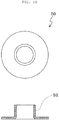
- FIG. 10 is a view showing an inner collar
- FIG. 11 is a view showing an outer collar.
- An exhaust manifold heat dissipation cover coupling device for thermal stress and vibration deflection includes an inner bush 10, an outer bush 20, an inner mesh elastic body 30, an outer mesh elastic body 40, an inner collar 50, and an outer collar 60.
- the exhaust manifold heat dissipation cover coupling device for thermal stress and vibration deflection is a device for coupling a heat dissipation cover to an exhaust manifold.
- the device is characterized by being able to improve the durability of parts including a heat dissipation cover by attenuating multi-directional vibration that is transmitted to the heat dissipation cover to prevent fasteners coupling the heat dissipation cover and an exhaust manifold such as bolts from being loosened by vibration transmitted from the exhaust manifold when installing the heat dissipation cover outside the exhaust manifold.
- the device is characterized by being able to prevent damage to various parts including a heat dissipation cover by flexibly coping with thermal deformation such as thermal expansion or thermal contraction due to thermal stress even if such thermal deformation is generated by high-temperature heat that is transmitted to the heat dissipation cover and several parts of the heat dissipation cover through fasteners such as bolts connected to an exhaust manifold.
- the device is characterized by being able to prevent frictional damage to a heat dissipation cover due to friction that is generated by a component elastically sliding to attenuate vibration.
- the inner bush 10 has a through-center portion and is coupled to the lower portion of a coupling hole 102 formed at a heat dissipation cover 100, that is, to the inner side of the heat dissipation cover 100.
- the outer bush 20 has a through-center portion and is coupled to the upper portion of a coupling hole 102 formed at a heat dissipation cover 100, that is, to the outer side of the heat dissipation cover 100.
- the inner mesh elastic body 30 has a through-center portion and is disposed in contact with the bottom of the inner bush 10.
- the outer mesh elastic body 40 has a through-center portion and is disposed in contact with the top of the outer bush 20.
- the inner mesh elastic body 30 and the outer mesh elastic body 40 independently slide without operation together with each other in contact with the bottom of the inner bush 10 and the top of the outer bush 20, respectively, and attenuate vibration or thermal stress transmitted from an exhaust manifold to prevent fasteners connecting and fixing the exhaust manifold and the heat dissipation cover 100 from being loosened, thereby protecting the heat dissipation cover 100 such that heat dissipation cover 100 can keep firmly coupled without separating from the exhaust manifold.
- the inner collar 50 has a through-center portion and is disposed in contact with the bottom of the inner mesh elastic body 30.
- the outer collar 60 has a through-center portion and is disposed in contact with the top of the outer mesh elastic body 40.
- the outer bush 10, outer mesh elastic body 40, and outer collar 60 are sequentially stacked over the coupling hole 102 of the heat dissipation cover 100 and the inner bush 10, inner mesh elastic body 30, and inner collar 50 are sequentially stacked under the coupling hole 102 of the heat dissipation cover 100 with the coupling hole 102 of the heat dissipation cover 100 therebetween.
- a fastener such as a bolt that couples the exhaust manifold and the heat dissipation cover 100 is inserted in the communicating through-center portions.
- the through-center portion of the inner bush 10 forms a push protrusion 12 protruding upward, and as shown in FIG. 4 , the outer bush 20 is a disc having a through-center portion.
- the inner bush 10 and the outer bush 20 are coupled first to the edge of the coupling hole 102 of the heat dissipation cover 100 not to be moved, and then the inner mesh elastic body 30, the outer mesh elastic body 40, the inner collar 50, and the outer collar 60 are coupled.
- the inner bush 10 and the outer bush 20 are coupled and fixed to the coupling hole 102 of the heat dissipation cover 100
- the inner bush 10 is placed inside the heat dissipation cover 100 and the outer bush 20 is placed outside the heat dissipation cover 100 such that the coupling hole 102 of the heat dissipation cover 100 and the through-center portions of the inner bush 10 and the outer bush 20 communicate with each other with the coupling hole 102 of the heat dissipation cover 100 therebetween.
- the bush protrusion 12 of the inner bush 10 is inserted through the coupling hole 102 of the heat dissipation cover 100 and the through-center portion of the outer bush 20 through the inside of the heat dissipation cover 100.
- the bush protrusion 12 of the inner bush 10 is bent outside where the outer bush 20 is disposed. Accordingly, as shown in FIG. 5 , the end of the bush protrusion 12 of the inner bush 10 presses the edge of the top of the through-center portion of the outer bush 20, whereby the inner bush 10 and the outer bush 20 are coupled and fixed to the coupling hole 102 of the heat dissipation cover 100.
- the protruding interface forms a step when the outer mesh elastic body 40 slides on the top of the outer bush 20, which causes a problem that the outer mesh elastic body 40 cannot smoothly slide on the top of the outer bush 20.
- the outer bush 20 is thinner than the inner bush 10 to prevent a step due to the thickness difference between the inner bush 10 and the outer bush 20 when the bush protrusion 12 of the inner bush 10 is bent to press the outer bush 20 such that the outer bush 20 and the inner bush 10 are coupled to the coupling hole 102 of the heat dissipation cover 100.
- the interface 16 may protrude from the top of the outer bush 20 or a step may be formed by the large thickness at the interface 16 when the bush protrusion 12 of the inner bush 10 is bent to be coupled to the outer bush 20, as described above. Such a step interferes with the outer mesh elastic body 40 sliding on the top of the outer bush 20, so the outer mesh elastic body 40 cannot smoothly slide.
- the inner bush 10 and the outer bush 20 are made of the same material as the inner mesh elastic body 30 and the outer mesh elastic body 40.
- the inner mesh elastic body 30 and the outer mesh elastic body 40 slide only on the contact surfaces of the inner bush 10 and the outer bush 20 not in direct contact with the heat dissipation cover 100 with the inner bush 10 and the outer bush 20 fixed to the coupling hole 102 of the heat dissipation cover 100, whereby frictional damage to the heat dissipation cover 100 is prevented.
- the inner mesh elastic body 30 and the outer mesh elastic body 40 that attenuate vibration while sliding by vibration generated by the exhaust manifold slide in direct contact with the inner bush 10 and the outer bush 20 made of the same material rather than in direct contact with the heat dissipation cover 100, whereby direction friction with the heat dissipation cove 100 is avoided and frictional damage is correspondingly prevented.
- the inner collar 50 and the outer collar 60 couple the inner mesh elastic body 30 and the outer mesh elastic body 40 in contact with the inner bush 10 and the outer bush 20, respectively.
- the through-center portion of the inner collar 50 forms an inner collar protrusion 52.
- the through-center portion of the outer collar 60 forms an outer collar protrusion 62 larger in diameter than the inner collar protrusion 52 of the inner collar 50.
- the inner collar protrusion 52 of the inner collar 50 is inserted into the outer collar protrusion 62 of the outer collar 60 and then the end of the inner collar protrusion 52 is bent toward the outer collar protrusion 62, whereby the inner collar 50 and the outer collar 60 are coupled to each other.
- the through-center portion of the inner mesh elastic body 30 forms a mesh protrusion 32 protruding upward.
- the mesh protrusion 32 is inserted in the through-center portion of the inner bush 20 and a first side gap 70 is formed between sides of the outer collar 60 and the inner mesh elastic body 30.
- a second side gap 80 is formed between sides of the outer mesh elastic body 40 and the inner mesh elastic body 30.
- the first side gap 70 formed between sides of the outer collar 60 and the inner mesh elastic body 30 and the second side gap 80 formed between sides of the outer mesh elastic body 40 and the inner mesh elastic body 30 enable the inner mesh elastic body 30 and the outer mesh elastic body 40 to independently slide left and right. and enable the inner collar 50 and the outer collar 60 to reduce vibration and thermal stress while sliding on the contact surfaces of the inner mesh elastic body 30 and the outer mesh elastic body 40 as much as the distances of the gaps.
- a height gap 90 is formed between the bottom of the outer collar 60 and the tops of the outer mesh elastic body 40 and the inner mesh elastic body 30.
- the inner mesh elastic body 30 and the outer mesh elastic body 40 or the inner collar 50 and the outer collar 60 relatively move up and down as much as the distance of the height gap 90, thereby reducing vibration and thermal stress in the height direction.
- the outer mesh elastic body 40, inner mesh elastic body 30, the outer collar 60, and the inner collar 50 that are components other than the inner bush 10 and the outer bush 20 coupled and fixed to the coupling hole 102 of the heat dissipation cover 100 slide left and right or move up and down, thereby attenuate multi-directional vibration or cope with thermal deformation such as thermal contraction or thermal expansion that is generated by thermal stress transmitted from the exhaust manifold.
Landscapes
- Engineering & Computer Science (AREA)
- Chemical & Material Sciences (AREA)
- Combustion & Propulsion (AREA)
- Mechanical Engineering (AREA)
- General Engineering & Computer Science (AREA)
- Physics & Mathematics (AREA)
- Acoustics & Sound (AREA)
- Exhaust Silencers (AREA)
Abstract
Description
- The present invention relates to an exhaust manifold heat dissipation cover coupling device for thermal stress and vibration deflection. In more detail, the present invention relates to a device having a function of preventing wear of a heat dissipation cover to couple an exhaust manifold heat dissipation cover, the device being able to improve the durability of various parts including a heat dissipation cover by attenuating multi-directional vibration that is transmitted from an exhaust manifold when the heat dissipation cover is installed outside the exhaust manifold, being able to prevent damage to parts due to thermal stress by flexibly coping with thermal deformation such as thermal contraction or thermal expansion even if the thermal deformation is generated by high-temperature heat transmitted from the exhaust manifold, and being able to prevent frictional damage of the heat dissipation cover due to friction by a component that slides to attenuate vibration.
- Exhaust gas that is produced after combustion of fuel in cylinders of an engine is collected into an exhaust manifold and the discharged outside through an exhaust pipe.
- In general, exhaust gas flowing through an exhaust manifold is at a considerably high temperature and the surface temperature of the exhaust manifold is at high temperature of over about 600 °C or higher due to the exhaust gas.
- Heat is transmitted to other engine parts around the exhaust manifold due to high temperature of the exhaust manifold, and accordingly, the possibility of thermal damage such as cracks generated in other parts around the exhaust manifold due to thermal expansion and thermal contraction by thermal stress is increased.
- In order to prevent such thermal damage, a heat protector or a heat dissipation cover for blocking heat that is transmitted form an exhaust manifold is usually installed outside the exhaust manifold.
- A heat dissipation cover is coupled to an exhaust manifold by fasteners such as bolts, and vibration generated by an engine is transmitted to the exhaust manifold, so the exhaust manifold vibrates in various directions. Accordingly, as load and shock are repeatedly applied to the fasteners coupling the exhaust manifold and the heat dissipation cover, there is a high possibility that the fasteners coupling the exhaust manifold and the heat dissipation cover are loosened or fatigue fracture of the fasteners is generated by fatigue load.
- Further, there is a problem that heat generated by the exhaust manifold is transmitted to the heat dissipation cover and other pats included in the heat dissipation cover through the fasteners such as bolts fixing the heat dissipation cover, whereby thermal damage such as cracks due to thermal stress may be generated in the heat dissipation cover and other parts.
- Friction is continuously generated between a heat dissipation cover and a component that slides left and right in direct contact with the heat dissipation cover to attenuate vibration of the exhaust manifold, whereby the heat dissipation cover having relatively low strength may be worn and correspondingly broken.
- Accordingly, there is a need for a new mean that can stably fix a heat dissipation cover and an exhaust manifold and can prevent wear and damage due to friction of the heat dissipation cover by a component sliding to attenuate vibration in order to reduce vibration and heat generated by the exhaust manifold and flexibly cope with thermal deformation due to thermal stress.
- The present invention has been made in an effort to solve the problems and an objective of the present invention is to provide a device having a function of preventing wear of a heat dissipation cover to couple an exhaust manifold heat dissipation cover, the device being able to improve the durability of various parts including a heat dissipation cover by attenuating multi-directional vibration that is transmitted from an exhaust manifold when the heat dissipation cover is installed outside the exhaust manifold, being able to prevent damage to parts due to thermal stress by flexibly coping with thermal deformation such as thermal contraction or thermal expansion even if the thermal deformation is generated by high-temperature heat transmitted from the exhaust manifold, and being able to prevent frictional damage of the heat dissipation cover due to friction by a component that slides to attenuate vibration.
- In order to achieve the objective of the present invention, an exhaust manifold heat dissipation cover coupling device for thermal stress and vibration deflection according to the present invention includes: an inner bush having a through-center portion and coupled to a lower portion of a coupling hole formed at a heat dissipation cover; an outer bush having a through-center portion and coupled to an upper portion of a coupling hole formed at the heat dissipation cover; an inner mesh elastic body having a through-center portion and disposed under the inner bush; an outer mesh elastic body having a through-center portion and disposed over the outer bush; an inner collar having a through-center portion and disposed under inner mesh elastic body; and an outer collar having a through-center portion and disposed over the outer mesh elastic body, in which the inner bush has a bush protrusion protruding upward and formed by the through-center portion and the outer bush is formed in a hollow disc shape; and the inner mesh elastic body and the outer mesh elastic body are made of the same material as the inner bush and the outer bush, the inner mesh elastic body and the outer mesh elastic body attenuate vibration and prevent wear of the heat dissipation cover by independently sliding only on contact surfaces of the inner bush and the outer bush, respectively.
- The inner bush and the outer bush may be first coupled and fixed to the coupling hole of the heat dissipation cover and then, the inner mesh elastic body, the outer mesh elastic body, the inner collar, and the outer collar may be coupled.
- The outer bush is thinner than the inner bush to prevent a step due to the thickness difference between the inner bush and the outer bush when the bush protrusion of the inner bush is bent to press the outer bush such that the outer bush and the inner bush are coupled to the coupling hole of the heat dissipation cover.
- According to the present invention, it is possible to improve the durability of parts including a heat dissipation cover by reducing thermal stress and vibration that are transmitted to the heat dissipation cover.
- Further, since the configuration is simple, installation and maintenance are easy and the number of parts is reduced, so the manufacturing cost can be decreased.
- Further, it is possible to prevent wear of the heat dissipation cover using a component that attenuates vibration.
- The above and other objectives, features and other advantages of the present invention will be more clearly understood from the following detailed description when taken in conjunction with the accompanying drawings, in which:
-
FIG. 1 is a view showing a cross-section when components of an exhaust manifold heat dissipation cover coupling device for thermal stress and vibration deflection according to an embodiment of the present invention have been assembled; -
FIG. 2 is a view showing an inner bush; -
FIG. 3 is a view showing the state in which the inner bush is fitted in an outside coupling hole of a heat dissipation cover; -
FIG. 4 is a view showing an outer bush; -
FIG. 5 is a view showing the state in which the outer bush is fitted an inside coupling hole of the heat dissipation cover; -
FIG. 6 is a view showing an inner mesh elastic body; -
FIG. 7 is a view showing the state in which an inner bush, an inner mesh elastic body, and an inner collar are coupled to the inner side of the heat dissipation cover; -
FIG. 8 is a view showing an outer mesh elastic body; -
FIG. 9 is a view showing the state in which an outer bush, an outer mesh elastic body, and an outer collar are coupled to the outer side of the heat dissipation cover; -
FIG. 10 is a view showing an inner collar; and -
FIG. 11 is a view showing an outer collar. - Hereinafter, exemplary embodiments of the present invention are described in detail with reference to the accompanying drawings. It should be noted that when components are given reference numerals in drawings, same components are given the same reference numerals even if they are shown in different drawings. In describing the present invention, well-known functions or constructions will not be described in detail since they may unnecessarily obscure the understanding of the present invention. Further, it should be noted that although embodiments of the present invention will be described below, the spirit of the present invention is not limited thereto and may be achieved in various ways by those skilled in the art.
-
FIG. 1 is a view showing a cross-section when components of an exhaust manifold heat dissipation cover coupling device for thermal stress and vibration deflection according to an embodiment of the present invention have been assembled,FIG. 2 is a view showing an inner bush,FIG. 3 is a view showing the state in which the inner bush is fitted in an outside coupling hole of a heat dissipation cover,FIG. 4 is a view showing an outer bush,FIG. 5 is a view showing the state in which the outer bush is fitted an inside coupling hole of the heat dissipation cover,FIG. 6 is a view showing an inner mesh elastic body,FIG. 7 is a view showing the state in which an inner bush, an inner mesh elastic body, and an inner collar are coupled to the inner side of the heat dissipation cover,FIG. 8 is a view showing an outer mesh elastic body,FIG. 9 is a view showing the state in which an outer bush, an outer mesh elastic body, and an outer collar are coupled to the outer side of the heat dissipation cover,FIG. 10 is a view showing an inner collar, andFIG. 11 is a view showing an outer collar. - An exhaust manifold heat dissipation cover coupling device for thermal stress and vibration deflection according to an embodiment of the present invention, referring to
FIGS. 1 to 11 , includes aninner bush 10, anouter bush 20, an inner meshelastic body 30, an outer meshelastic body 40, aninner collar 50, and anouter collar 60. - First, the exhaust manifold heat dissipation cover coupling device for thermal stress and vibration deflection according to the present invention is a device for coupling a heat dissipation cover to an exhaust manifold. The device is characterized by being able to improve the durability of parts including a heat dissipation cover by attenuating multi-directional vibration that is transmitted to the heat dissipation cover to prevent fasteners coupling the heat dissipation cover and an exhaust manifold such as bolts from being loosened by vibration transmitted from the exhaust manifold when installing the heat dissipation cover outside the exhaust manifold.
- Further, the device is characterized by being able to prevent damage to various parts including a heat dissipation cover by flexibly coping with thermal deformation such as thermal expansion or thermal contraction due to thermal stress even if such thermal deformation is generated by high-temperature heat that is transmitted to the heat dissipation cover and several parts of the heat dissipation cover through fasteners such as bolts connected to an exhaust manifold.
- Further, the device is characterized by being able to prevent frictional damage to a heat dissipation cover due to friction that is generated by a component elastically sliding to attenuate vibration.
- Hereafter, the components of an exhaust manifold heat dissipation cover coupling device for thermal stress and vibration deflection and the functions thereof are described in detail.
- Referring to
FIGS. 1 ,2 , and3 , theinner bush 10 has a through-center portion and is coupled to the lower portion of acoupling hole 102 formed at aheat dissipation cover 100, that is, to the inner side of theheat dissipation cover 100. - Referring to
FIGS. 1 ,4 , and5 , theouter bush 20 has a through-center portion and is coupled to the upper portion of acoupling hole 102 formed at aheat dissipation cover 100, that is, to the outer side of theheat dissipation cover 100. - Referring to
FIGS. 1 ,6 , and7 , the inner meshelastic body 30 has a through-center portion and is disposed in contact with the bottom of theinner bush 10. - Referring to
FIGS. 1 ,8 , and9 , the outer meshelastic body 40 has a through-center portion and is disposed in contact with the top of theouter bush 20. - The inner mesh
elastic body 30 and the outer meshelastic body 40 independently slide without operation together with each other in contact with the bottom of theinner bush 10 and the top of theouter bush 20, respectively, and attenuate vibration or thermal stress transmitted from an exhaust manifold to prevent fasteners connecting and fixing the exhaust manifold and theheat dissipation cover 100 from being loosened, thereby protecting theheat dissipation cover 100 such thatheat dissipation cover 100 can keep firmly coupled without separating from the exhaust manifold. - Referring to
FIGS. 1 ,7 , and10 , theinner collar 50 has a through-center portion and is disposed in contact with the bottom of the inner meshelastic body 30. - Referring to
FIGS. 1 ,8 , and10 , theouter collar 60 has a through-center portion and is disposed in contact with the top of the outer meshelastic body 40. - That is, as shown in
FIG. 1 , theouter bush 10, outer meshelastic body 40, andouter collar 60 are sequentially stacked over thecoupling hole 102 of theheat dissipation cover 100 and theinner bush 10, inner meshelastic body 30, andinner collar 50 are sequentially stacked under thecoupling hole 102 of theheat dissipation cover 100 with thecoupling hole 102 of theheat dissipation cover 100 therebetween. - The
coupling hole 102 of the heat dissipation cover 100, and the through-center portions of theouter bush 20, the outer meshelastic body 40, theouter collar 60, theinner bush 10, the inner meshelastic body 30, and theinner collar 50 communicate with each other. A fastener such as a bolt that couples the exhaust manifold and theheat dissipation cover 100 is inserted in the communicating through-center portions. - Referring to
FIG. 2 , the through-center portion of theinner bush 10 forms apush protrusion 12 protruding upward, and as shown inFIG. 4 , theouter bush 20 is a disc having a through-center portion. - As shown in
FIGS. 3 and5 , theinner bush 10 and theouter bush 20 are coupled first to the edge of thecoupling hole 102 of theheat dissipation cover 100 not to be moved, and then the inner meshelastic body 30, the outer meshelastic body 40, theinner collar 50, and theouter collar 60 are coupled. - Referring to
FIGS. 3 and5 , when theinner bush 10 and theouter bush 20 are coupled and fixed to thecoupling hole 102 of theheat dissipation cover 100, first, theinner bush 10 is placed inside theheat dissipation cover 100 and theouter bush 20 is placed outside theheat dissipation cover 100 such that thecoupling hole 102 of theheat dissipation cover 100 and the through-center portions of theinner bush 10 and theouter bush 20 communicate with each other with thecoupling hole 102 of theheat dissipation cover 100 therebetween. - The
bush protrusion 12 of theinner bush 10, as shown inFIG. 1 , is inserted through thecoupling hole 102 of theheat dissipation cover 100 and the through-center portion of theouter bush 20 through the inside of theheat dissipation cover 100. - Thereafter, the
bush protrusion 12 of theinner bush 10, as shown inFIG. 1 , is bent outside where theouter bush 20 is disposed. Accordingly, as shown inFIG. 5 , the end of thebush protrusion 12 of theinner bush 10 presses the edge of the top of the through-center portion of theouter bush 20, whereby theinner bush 10 and theouter bush 20 are coupled and fixed to thecoupling hole 102 of theheat dissipation cover 100. - Referring to
FIGS. 1 to 5 , when thepush protrusion 12 of theinner bush 10 is bent to press the edge of the center portion of theouter bush 20, aninterface 16 between the end of thebent bush protrusion 12 of theinner bush 10 and theouter bush 20 is formed on the inner surface of the through-center portion of theouter bush 20 not to protrude from the top of theouter bush 20. - If the
interface 16 protrudes from the top of theouter bush 20, the protruding interface forms a step when the outer meshelastic body 40 slides on the top of theouter bush 20, which causes a problem that the outer meshelastic body 40 cannot smoothly slide on the top of theouter bush 20. - The
outer bush 20 is thinner than theinner bush 10 to prevent a step due to the thickness difference between theinner bush 10 and theouter bush 20 when thebush protrusion 12 of theinner bush 10 is bent to press theouter bush 20 such that theouter bush 20 and theinner bush 10 are coupled to thecoupling hole 102 of theheat dissipation cover 100. - If the thickness of the
outer bush 20 is the same as or larger than the thickness of theinner bush 10, theinterface 16 may protrude from the top of theouter bush 20 or a step may be formed by the large thickness at theinterface 16 when thebush protrusion 12 of theinner bush 10 is bent to be coupled to theouter bush 20, as described above. Such a step interferes with the outer meshelastic body 40 sliding on the top of theouter bush 20, so the outer meshelastic body 40 cannot smoothly slide. - Referring to
FIGS. 1 ,7 , and9 , theinner bush 10 and theouter bush 20 are made of the same material as the inner meshelastic body 30 and the outer meshelastic body 40. The inner meshelastic body 30 and the outer meshelastic body 40 slide only on the contact surfaces of theinner bush 10 and theouter bush 20 not in direct contact with theheat dissipation cover 100 with theinner bush 10 and theouter bush 20 fixed to thecoupling hole 102 of theheat dissipation cover 100, whereby frictional damage to theheat dissipation cover 100 is prevented. - That is, the inner mesh
elastic body 30 and the outer meshelastic body 40 that attenuate vibration while sliding by vibration generated by the exhaust manifold slide in direct contact with theinner bush 10 and theouter bush 20 made of the same material rather than in direct contact with theheat dissipation cover 100, whereby direction friction with theheat dissipation cove 100 is avoided and frictional damage is correspondingly prevented. - The
inner collar 50 and theouter collar 60 couple the inner meshelastic body 30 and the outer meshelastic body 40 in contact with theinner bush 10 and theouter bush 20, respectively. - Referring to
FIG. 10 , the through-center portion of theinner collar 50 forms aninner collar protrusion 52. Referring toFIG. 11 , the through-center portion of theouter collar 60 forms anouter collar protrusion 62 larger in diameter than theinner collar protrusion 52 of theinner collar 50. - Referring to
FIGS. 1 and9 , theinner collar protrusion 52 of theinner collar 50 is inserted into theouter collar protrusion 62 of theouter collar 60 and then the end of theinner collar protrusion 52 is bent toward theouter collar protrusion 62, whereby theinner collar 50 and theouter collar 60 are coupled to each other. - Referring to
FIGS. 1 and6 , the through-center portion of the inner meshelastic body 30 forms amesh protrusion 32 protruding upward. Themesh protrusion 32 is inserted in the through-center portion of theinner bush 20 and afirst side gap 70 is formed between sides of theouter collar 60 and the inner meshelastic body 30. - Referring to
FIG. 1 , asecond side gap 80 is formed between sides of the outer meshelastic body 40 and the inner meshelastic body 30. - The
first side gap 70 formed between sides of theouter collar 60 and the inner meshelastic body 30 and thesecond side gap 80 formed between sides of the outer meshelastic body 40 and the inner meshelastic body 30 enable the inner meshelastic body 30 and the outer meshelastic body 40 to independently slide left and right. and enable theinner collar 50 and theouter collar 60 to reduce vibration and thermal stress while sliding on the contact surfaces of the inner meshelastic body 30 and the outer meshelastic body 40 as much as the distances of the gaps. - Referring to
FIG. 1 , aheight gap 90 is formed between the bottom of theouter collar 60 and the tops of the outer meshelastic body 40 and the inner meshelastic body 30. The inner meshelastic body 30 and the outer meshelastic body 40 or theinner collar 50 and theouter collar 60 relatively move up and down as much as the distance of theheight gap 90, thereby reducing vibration and thermal stress in the height direction. - That is, the outer mesh
elastic body 40, inner meshelastic body 30, theouter collar 60, and theinner collar 50 that are components other than theinner bush 10 and theouter bush 20 coupled and fixed to thecoupling hole 102 of theheat dissipation cover 100 slide left and right or move up and down, thereby attenuate multi-directional vibration or cope with thermal deformation such as thermal contraction or thermal expansion that is generated by thermal stress transmitted from the exhaust manifold. - The above description merely explains the spirit of the present invention and the present invention may be changed, modified, and replaced in various ways without departing from the spirit of the present invention by those skilled in the art. Accordingly, the embodiments described herein and the accompanying drawings are provided merely not to limit, but to explain the spirit of the present invention, and the spirit of the present invention is not limited by the embodiments and the accompanying drawings. The protective range of the present invention should be construed by the following claims and the scope and spirit of the present invention should be construed as being included in the patent right of the present invention.
Claims (6)
- An exhaust manifold heat dissipation cover coupling device for thermal stress and vibration deflection, the device comprising:an inner bush having a through-center portion and coupled to a lower portion of a coupling hole formed at a heat dissipation cover;an outer bush having a through-center portion and coupled to an upper portion of a coupling hole formed at the heat dissipation cover;an inner mesh elastic body having a through-center portion and disposed under the inner bush;an outer mesh elastic body having a through-center portion and disposed over the outer bush;an inner collar having a through-center portion and disposed under inner mesh elastic body; andan outer collar having a through-center portion and disposed over the outer mesh elastic body,wherein the inner bush has a bush protrusion formed by the through-center portion and the outer bush is formed in a hollow disc shape;the inner mesh elastic body and the outer mesh elastic body are made of the same material as the inner bush and the outer bush, the inner mesh elastic body and the outer mesh elastic body attenuate vibration and prevent wear of the heat dissipation cover by independently sliding only on contact surfaces of the inner bush and the outer bush, respectively.
- The exhaust manifold heat dissipation cover coupling device for thermal stress and vibration deflection according to claim 1, wherein the inner bush and the outer bush are first coupled and fixed to the coupling hole of the heat dissipation cover and then, the inner mesh elastic body, the outer mesh elastic body, the inner collar, and the outer collar are coupled.
- The exhaust manifold heat dissipation cover coupling device for thermal stress and vibration deflection according to claim 1 or 2, wherein the outer bush is thinner than the inner bush to prevent a step due to a thickness difference between the inner bush and the outer bush when the outer bush and the inner bush are coupled to the coupling hole of the heat dissipation cover.
- The exhaust manifold heat dissipation cover coupling device for thermal stress and vibration deflection according to one of claims 1-3, wherein when the push protrusion of the inner bush is bent to be coupled to the heat dissipation cover while pressing an edge of a center portion of the outer bush, an interface between the end of the bent bush protrusion of the inner bush and the outer bush is formed on an inner surface of the through-center portion of the outer bush not to protrude from a top of the outer bush.
- The exhaust manifold heat dissipation cover coupling device for thermal stress and vibration deflection according to one of claims 1-4, wherein a first side gap is formed between sides of the outer collar and the inner mesh elastic body and a second side gap is formed between sides of the outer mesh elastic body and the inner mesh elastic body.
- The exhaust manifold heat dissipation cover coupling device for thermal stress and vibration deflection according to one of claims 1-5, wherein a height gap is formed between a bottom of the outer collar and tops of the outer mesh elastic body and the inner mesh elastic body.
Applications Claiming Priority (1)
| Application Number | Priority Date | Filing Date | Title |
|---|---|---|---|
| KR1020200014272A KR102179977B1 (en) | 2020-02-06 | 2020-02-06 | Exhaust manifold heat dissipation cover coupling device for thermal stress and vibration deflection |
Publications (2)
| Publication Number | Publication Date |
|---|---|
| EP3862546A1 true EP3862546A1 (en) | 2021-08-11 |
| EP3862546B1 EP3862546B1 (en) | 2024-04-17 |
Family
ID=73642449
Family Applications (1)
| Application Number | Title | Priority Date | Filing Date |
|---|---|---|---|
| EP21155441.5A Active EP3862546B1 (en) | 2020-02-06 | 2021-02-05 | Exhaust manifold heat dissipation cover coupling device for thermal stress and vibration deflection |
Country Status (3)
| Country | Link |
|---|---|
| US (1) | US11408323B2 (en) |
| EP (1) | EP3862546B1 (en) |
| KR (1) | KR102179977B1 (en) |
Families Citing this family (2)
| Publication number | Priority date | Publication date | Assignee | Title |
|---|---|---|---|---|
| DE202020101595U1 (en) * | 2020-03-25 | 2021-06-28 | Reinz-Dichtungs-Gmbh | Decoupling element for heat shields |
| CN112696258B (en) * | 2020-12-23 | 2022-04-22 | 重汽(重庆)轻型汽车有限公司 | Control method for thermal deformation design of exhaust manifold |
Citations (3)
| Publication number | Priority date | Publication date | Assignee | Title |
|---|---|---|---|---|
| JP2000274415A (en) * | 1999-03-24 | 2000-10-03 | Best:Kk | Fixture and its temporary fixing method |
| JP2010156372A (en) * | 2008-12-26 | 2010-07-15 | Sanwa Packing Kogyo Co Ltd | Mount member |
| KR20150071487A (en) * | 2013-12-18 | 2015-06-26 | 현대자동차주식회사 | Panel fastening device for absorbing shock |
Family Cites Families (10)
| Publication number | Priority date | Publication date | Assignee | Title |
|---|---|---|---|---|
| US4921203A (en) * | 1989-01-30 | 1990-05-01 | Buell Industries, Inc. | Spring element for a shock isolating mount |
| JP3490927B2 (en) * | 1999-05-19 | 2004-01-26 | ニチアス株式会社 | How to attach a vibrating floating washer to the heat shield |
| DE10021575C2 (en) * | 2000-05-03 | 2002-09-19 | Elringklinger Ag | Device for the acoustically decoupled attachment of heat shields or similar easily vibratable components |
| JP2005030570A (en) * | 2003-07-11 | 2005-02-03 | Nichias Corp | Vibration-proof heat shielding plate |
| JP4398222B2 (en) * | 2003-10-29 | 2010-01-13 | ニチアス株式会社 | Anti-vibration heat shield |
| JP4472325B2 (en) * | 2003-12-25 | 2010-06-02 | 三和パッキング工業株式会社 | Shock absorber |
| KR100999631B1 (en) | 2008-08-07 | 2010-12-08 | 기아자동차주식회사 | Heat protecting system of exhaust manifold |
| JP4901992B1 (en) * | 2010-12-22 | 2012-03-21 | 三和パッキング工業株式会社 | Shock absorber and metal cover |
| KR101579895B1 (en) * | 2014-07-15 | 2015-12-23 | 주식회사 선일다이파스 | Panel fastening device |
| JP6434069B2 (en) * | 2017-02-01 | 2018-12-05 | ニチアス株式会社 | Connector |
-
2020
- 2020-02-06 KR KR1020200014272A patent/KR102179977B1/en active IP Right Grant
-
2021
- 2021-02-04 US US17/167,472 patent/US11408323B2/en active Active
- 2021-02-05 EP EP21155441.5A patent/EP3862546B1/en active Active
Patent Citations (3)
| Publication number | Priority date | Publication date | Assignee | Title |
|---|---|---|---|---|
| JP2000274415A (en) * | 1999-03-24 | 2000-10-03 | Best:Kk | Fixture and its temporary fixing method |
| JP2010156372A (en) * | 2008-12-26 | 2010-07-15 | Sanwa Packing Kogyo Co Ltd | Mount member |
| KR20150071487A (en) * | 2013-12-18 | 2015-06-26 | 현대자동차주식회사 | Panel fastening device for absorbing shock |
Also Published As
| Publication number | Publication date |
|---|---|
| US20210246821A1 (en) | 2021-08-12 |
| US11408323B2 (en) | 2022-08-09 |
| KR102179977B1 (en) | 2020-11-17 |
| EP3862546B1 (en) | 2024-04-17 |
Similar Documents
| Publication | Publication Date | Title |
|---|---|---|
| EP3862546A1 (en) | Exhaust manifold heat dissipation cover coupling device for thermal stress and vibration deflection | |
| US6901757B2 (en) | Heat shield arrangement with sealing element | |
| EP1607598B1 (en) | Decoupling joint for combustion engine exhaust pipes | |
| US20110067952A1 (en) | Heat shield and an insulating isolator for the heat shield | |
| JP6381624B2 (en) | Gasket assembly | |
| JPH08500887A (en) | Metal sealing element | |
| US3187643A (en) | Pistons for internal combustion engines | |
| US10648438B2 (en) | Multipart insulating element, in particular for a fuel injection device | |
| KR102364131B1 (en) | Tubular combustion chamber with ceramic cladding | |
| JPH07317514A (en) | Installing method of ceramic valve guide assembled body | |
| EP3357643A1 (en) | Heatshield for a band clamp | |
| US20230130521A1 (en) | Combustion chamber having a ceramic heat shield and seal | |
| JP2014500436A (en) | High temperature piston | |
| JP4092382B2 (en) | Metal fitting with fiber insert | |
| US20200256416A1 (en) | Externally-damped electromechanical valve assemblies | |
| CN102477875B (en) | Valve driving mechanism for internal combustion engines | |
| JPH087246Y2 (en) | Assembly structure of ceramic combustor | |
| JPH089400Y2 (en) | Cylinder liner mounting structure | |
| JP2018523775A (en) | Insulating isolator assembly | |
| JPH0526111A (en) | Heat insulating piston | |
| JPH0319902B2 (en) | ||
| JP2008190514A (en) | Mounting structure of heat insulation member | |
| JP2591062Y2 (en) | Exhaust manifold mounting structure | |
| US6212770B1 (en) | Method of forming a roller assembly | |
| KR100657692B1 (en) | Piston bush |
Legal Events
| Date | Code | Title | Description |
|---|---|---|---|
| PUAI | Public reference made under article 153(3) epc to a published international application that has entered the european phase |
Free format text: ORIGINAL CODE: 0009012 |
|
| STAA | Information on the status of an ep patent application or granted ep patent |
Free format text: STATUS: THE APPLICATION HAS BEEN PUBLISHED |
|
| AK | Designated contracting states |
Kind code of ref document: A1 Designated state(s): AL AT BE BG CH CY CZ DE DK EE ES FI FR GB GR HR HU IE IS IT LI LT LU LV MC MK MT NL NO PL PT RO RS SE SI SK SM TR |
|
| STAA | Information on the status of an ep patent application or granted ep patent |
Free format text: STATUS: REQUEST FOR EXAMINATION WAS MADE |
|
| 17P | Request for examination filed |
Effective date: 20220209 |
|
| RBV | Designated contracting states (corrected) |
Designated state(s): AL AT BE BG CH CY CZ DE DK EE ES FI FR GB GR HR HU IE IS IT LI LT LU LV MC MK MT NL NO PL PT RO RS SE SI SK SM TR |
|
| STAA | Information on the status of an ep patent application or granted ep patent |
Free format text: STATUS: EXAMINATION IS IN PROGRESS |
|
| 17Q | First examination report despatched |
Effective date: 20230310 |
|
| P01 | Opt-out of the competence of the unified patent court (upc) registered |
Effective date: 20230504 |
|
| GRAP | Despatch of communication of intention to grant a patent |
Free format text: ORIGINAL CODE: EPIDOSNIGR1 |
|
| STAA | Information on the status of an ep patent application or granted ep patent |
Free format text: STATUS: GRANT OF PATENT IS INTENDED |
|
| INTG | Intention to grant announced |
Effective date: 20231108 |
|
| GRAS | Grant fee paid |
Free format text: ORIGINAL CODE: EPIDOSNIGR3 |
|
| GRAA | (expected) grant |
Free format text: ORIGINAL CODE: 0009210 |
|
| STAA | Information on the status of an ep patent application or granted ep patent |
Free format text: STATUS: THE PATENT HAS BEEN GRANTED |
|
| AK | Designated contracting states |
Kind code of ref document: B1 Designated state(s): AL AT BE BG CH CY CZ DE DK EE ES FI FR GB GR HR HU IE IS IT LI LT LU LV MC MK MT NL NO PL PT RO RS SE SI SK SM TR |
|
| REG | Reference to a national code |
Ref country code: GB Ref legal event code: FG4D |
|
| REG | Reference to a national code |
Ref country code: CH Ref legal event code: EP |
|
| REG | Reference to a national code |
Ref country code: DE Ref legal event code: R096 Ref document number: 602021011765 Country of ref document: DE |
|
| REG | Reference to a national code |
Ref country code: IE Ref legal event code: FG4D |