JP6381624B2 - Gasket assembly - Google Patents
Gasket assembly Download PDFInfo
- Publication number
- JP6381624B2 JP6381624B2 JP2016500526A JP2016500526A JP6381624B2 JP 6381624 B2 JP6381624 B2 JP 6381624B2 JP 2016500526 A JP2016500526 A JP 2016500526A JP 2016500526 A JP2016500526 A JP 2016500526A JP 6381624 B2 JP6381624 B2 JP 6381624B2
- Authority
- JP
- Japan
- Prior art keywords
- gasket
- sealing bead
- layer
- assembly
- primary sealing
- Prior art date
- Legal status (The legal status is an assumption and is not a legal conclusion. Google has not performed a legal analysis and makes no representation as to the accuracy of the status listed.)
- Expired - Fee Related
Links
Images


Classifications
-
- F—MECHANICAL ENGINEERING; LIGHTING; HEATING; WEAPONS; BLASTING
- F16—ENGINEERING ELEMENTS AND UNITS; GENERAL MEASURES FOR PRODUCING AND MAINTAINING EFFECTIVE FUNCTIONING OF MACHINES OR INSTALLATIONS; THERMAL INSULATION IN GENERAL
- F16J—PISTONS; CYLINDERS; SEALINGS
- F16J15/00—Sealings
- F16J15/02—Sealings between relatively-stationary surfaces
- F16J15/06—Sealings between relatively-stationary surfaces with solid packing compressed between sealing surfaces
- F16J15/08—Sealings between relatively-stationary surfaces with solid packing compressed between sealing surfaces with exclusively metal packing
- F16J15/0818—Flat gaskets
- F16J15/0825—Flat gaskets laminated
-
- F—MECHANICAL ENGINEERING; LIGHTING; HEATING; WEAPONS; BLASTING
- F16—ENGINEERING ELEMENTS AND UNITS; GENERAL MEASURES FOR PRODUCING AND MAINTAINING EFFECTIVE FUNCTIONING OF MACHINES OR INSTALLATIONS; THERMAL INSULATION IN GENERAL
- F16J—PISTONS; CYLINDERS; SEALINGS
- F16J15/00—Sealings
- F16J15/02—Sealings between relatively-stationary surfaces
- F16J15/06—Sealings between relatively-stationary surfaces with solid packing compressed between sealing surfaces
- F16J15/08—Sealings between relatively-stationary surfaces with solid packing compressed between sealing surfaces with exclusively metal packing
- F16J15/0818—Flat gaskets
- F16J2015/085—Flat gaskets without fold over
-
- F—MECHANICAL ENGINEERING; LIGHTING; HEATING; WEAPONS; BLASTING
- F16—ENGINEERING ELEMENTS AND UNITS; GENERAL MEASURES FOR PRODUCING AND MAINTAINING EFFECTIVE FUNCTIONING OF MACHINES OR INSTALLATIONS; THERMAL INSULATION IN GENERAL
- F16J—PISTONS; CYLINDERS; SEALINGS
- F16J15/00—Sealings
- F16J15/02—Sealings between relatively-stationary surfaces
- F16J15/06—Sealings between relatively-stationary surfaces with solid packing compressed between sealing surfaces
- F16J15/08—Sealings between relatively-stationary surfaces with solid packing compressed between sealing surfaces with exclusively metal packing
- F16J15/0818—Flat gaskets
- F16J2015/0862—Flat gaskets with a bore ring
Description
発明の背景
1.発明の分野
本発明は一般的に、内燃機関で用いるための多層ガスケットアセンブリに関する。
BACKGROUND OF THE INVENTION The present invention relates generally to multilayer gasket assemblies for use in internal combustion engines.
2.関連技術
多層ガスケットアセンブリは伝統的に、燃焼ガス、冷却水、潤滑油などの漏れを防止するために、内燃機関などの機械系または装置の2つの嵌め合わせ構成要素同士の間の封止を形成するのに用いられる。一般的な適用例は、エンジンブロックとシリンダヘッドとの間およびエンジンブロックと排気マニフォルドとの間に多層ガスケットアセンブリを載置することに係る。シリンダヘッドガスケットは典型的に、エンジンのシリンダボアの周りに延在して、シリンダボア内の高圧燃焼ガスを封止し、かつ油および冷媒の通過を封止する。排気マニフォルドガスケットは典型的に、エンジンの排気口の周りに延在して、エンジンから排気系に流れる高温の排気ガスを封止する。一旦設置されると、多層ガスケットアセンブリは、エンジン構成要素のボルトで締結された接続からの荷重を支え、この荷重に依拠してその間の十分な封止を与える。
2. Related Art Multilayer gasket assemblies traditionally form a seal between two mating components of a mechanical system or device, such as an internal combustion engine, to prevent leakage of combustion gases, cooling water, lubricants, etc. Used to do. A typical application involves placing a multilayer gasket assembly between the engine block and the cylinder head and between the engine block and the exhaust manifold. The cylinder head gasket typically extends around the cylinder bore of the engine to seal the high pressure combustion gases in the cylinder bore and to seal the passage of oil and refrigerant. The exhaust manifold gasket typically extends around the exhaust port of the engine to seal hot exhaust gas flowing from the engine to the exhaust system. Once installed, the multi-layer gasket assembly supports the load from the bolted connections of engine components and relies on this load to provide a sufficient seal therebetween.
今日の内燃機関の多数は、エンジンブロックのシリンダボア内に挿入されるシリンダライナーとしても公知のスリーブを利用する。スリーブは一般的に形状が筒状であり、シリンダボア中にエンジンブロックとピストンとの間に配設される。しばしば、スリーブは、エンジンブロックに用いられるのとは異なる金属または合金からなる。たとえば、内燃機関は、アルミニウムからなるエンジンブロックと、鋼または鋳鉄からなるスリーブとを有することがある。これらの金属は熱膨張率が異なり、そのために、スリーブがシリンダボアに対して軸方向に伸縮してしまうことがある。たとえば、スリーブが高温に晒されると、軸方向に伸びてガスケットアセンブリを壊してしまうことがあり、永久的にこれを変形させてしまう可能性がある。ガスケットアセンブリのそのような永久的な変形は問題である。なぜなら、ガスケットアセンブリの弾性の一部が失われ、これによりガスケットの封止能力を損なうことがあるからである。次に、スリーブがより低い温度に晒されるにつれて、これは軸方向に縮んで、スリーブと変形したガスケットアセンブリとの間に間隙が残り、これにより小さな燃焼ガスの漏れが生じることがある。 Many of today's internal combustion engines utilize a sleeve that is also known as a cylinder liner that is inserted into the cylinder bore of the engine block. The sleeve is generally cylindrical in shape and is disposed in the cylinder bore between the engine block and the piston. Often the sleeve is made of a different metal or alloy than is used for the engine block. For example, an internal combustion engine may have an engine block made of aluminum and a sleeve made of steel or cast iron. These metals have different coefficients of thermal expansion, which may cause the sleeve to expand and contract axially relative to the cylinder bore. For example, when the sleeve is exposed to high temperatures, it may stretch in the axial direction and break the gasket assembly, which may permanently deform it. Such permanent deformation of the gasket assembly is a problem. This is because part of the elasticity of the gasket assembly is lost, which can impair the sealing ability of the gasket. Then, as the sleeve is exposed to lower temperatures, it shrinks in the axial direction, leaving a gap between the sleeve and the deformed gasket assembly, which can cause small combustion gas leaks.
そのような多層ガスケットアセンブリは典型的に、少なくとも1つのアパーチャに外接する内側端縁を有する少なくとも1つのガスケット層を含む。ガスケット層は、アパーチャから径方向に離間される外側領域も有する。シリンダヘッドガスケット適用例では、アパーチャは典型的に内燃機関のシリンダボアに対応する。これに代えて、排気マニフォルドガスケット適用例では、アパーチャは典型的に内燃機関の排気口に対応する。少なくとも1つのガスケット層は、互いに対して積層される複数のガスケット層であり得る。ガスケット層はしばしば、内側端縁と外側領域との間に配設されてガスケットアセンブリの封止能力を向上させる封止ビードを含む。典型的に、封止ビードは各々のアパーチャの周りに環状に延在する。封止ビードは、アパーチャの周りに周方向にかつ第1の径方向長さに沿って径方向に延在する一次封止ビードを含んでもよい。封止ビードはさらに、一次封止ビードと内側端縁との間にガスケット層に沿って配設される二次封止ビードを含んでもよく、二次封止ビードは第2の径方向長さに沿って延在する。 Such multi-layer gasket assemblies typically include at least one gasket layer having an inner edge that circumscribes at least one aperture. The gasket layer also has an outer region that is radially spaced from the aperture. In cylinder head gasket applications, the aperture typically corresponds to a cylinder bore in an internal combustion engine. Alternatively, in the exhaust manifold gasket application, the aperture typically corresponds to the exhaust port of the internal combustion engine. The at least one gasket layer may be a plurality of gasket layers that are stacked against each other. The gasket layer often includes a sealing bead disposed between the inner edge and the outer region to improve the sealing capability of the gasket assembly. Typically, the sealing bead extends annularly around each aperture. The sealing bead may include a primary sealing bead extending circumferentially around the aperture and radially along the first radial length. The sealing bead may further include a secondary sealing bead disposed along the gasket layer between the primary sealing bead and the inner edge, the secondary sealing bead having a second radial length. Extending along.
いくつかの多層ガスケットは、ガスケット層同士の間に配設されるストッパ層も含む。たとえば、1つの公知の多層ガスケットは、第2の封止ビードから内側端縁に延在し、かつ第2の封止ビードの第2の径方向長さに完全に重なるストッパ層を含む。別の公知の多層ガスケットでは、ストッパ層はガスケット層の外側領域から延在し、第2の封止ビードの第2の径方向長さに沿って終端して、一次封止特徴の第1の径方向長さに完全に重なりかつ二次封止特徴の第2の径方向長さに部分的に重なる。しかしながら、そのようなストッパ層は、熱負荷の際にシリンダボアスリーブの伸縮からの永久的な変形に対抗する多層ガスケットの十分な保護を提供しないことがある。 Some multilayer gaskets also include a stopper layer disposed between the gasket layers. For example, one known multilayer gasket includes a stopper layer that extends from the second sealing bead to the inner edge and completely overlaps the second radial length of the second sealing bead. In another known multilayer gasket, the stopper layer extends from the outer region of the gasket layer and terminates along the second radial length of the second sealing bead to provide a first sealing feature first. Fully overlaps the radial length and partially overlaps the second radial length of the secondary sealing feature. However, such a stopper layer may not provide sufficient protection of the multilayer gasket against permanent deformation from expansion and contraction of the cylinder bore sleeve during thermal loading.
発明の要約
少なくとも1つのアパーチャに外接する内側端縁とアパーチャから径方向に離間される外側領域とを有する少なくとも1つのガスケット層を含むガスケットアセンブリ。少なくとも1つの一次封止ビードは、内側端縁と外側領域との間にガスケット層に沿って配設される。一次封止ビードは、アパーチャの周りに周方向にかつ第1の径方向長さに沿って径方向に延在する。少なくとも1つの二次封止ビードは、一次封止ビードと内側端縁との間にガスケット層に沿って配設され、二次封止ビードは第2の径方向長さに沿って延在する。ストッパ層はガスケット層の少なくとも一部に隣接して配設される。ストッパ層は外側領域からガスケット層の内側端縁に径方向に延在する。応じて、ストッパ層は、一次封止ビードの第1の径方向長さおよび二次封止ビードの第2の径方向長さに完全に重なって、ガスケット層の内側端縁に隣接して増大したガスケット弾性を提供する。
SUMMARY OF THE INVENTION A gasket assembly comprising at least one gasket layer having an inner edge circumscribing at least one aperture and an outer region radially spaced from the aperture. At least one primary sealing bead is disposed along the gasket layer between the inner edge and the outer region. The primary sealing bead extends circumferentially around the aperture and radially along the first radial length. At least one secondary sealing bead is disposed along the gasket layer between the primary sealing bead and the inner edge, and the secondary sealing bead extends along a second radial length. . The stopper layer is disposed adjacent to at least a portion of the gasket layer. The stopper layer extends radially from the outer region to the inner edge of the gasket layer. Accordingly, the stopper layer increases adjacent to the inner edge of the gasket layer, completely overlapping the first radial length of the primary sealing bead and the second radial length of the secondary sealing bead. Provides gasket elasticity.
そのようなガスケットアセンブリは、ストッパ層が外側領域から内側領域に延在し、一次封止ビードおよび二次封止ビードの両方の全径方向長さに重なるという点で有利である。この特定的な構造により、より弾性的でありかつ熱負荷を経る際のスリーブの伸縮により良好に対処することができるガスケットアセンブリが得られる。より具体的には、両方のビードに重なることにより、膨張するスリーブによってガスケットアセンブリに加わる圧縮力が両方の封止ビードの全径方向長さにわたって分散される。これにより、スリーブが高温下で膨張する際に封止ビードのうち1つを壊してしまうまたは永久的に変形させてしまうことが防止される。内側端縁に隣接するガスケットアセンブリの弾性が保全されるので、スリーブとガスケットアセンブリとの間に間隙は生じず、小さな気体の漏れが排除される。 Such a gasket assembly is advantageous in that the stopper layer extends from the outer region to the inner region and overlaps the full radial length of both the primary sealing bead and the secondary sealing bead. This particular construction results in a gasket assembly that is more elastic and can better cope with the expansion and contraction of the sleeve when subjected to thermal loads. More specifically, by overlapping both beads, the compressive force applied to the gasket assembly by the expanding sleeve is distributed over the entire radial length of both sealing beads. This prevents one of the sealing beads from being broken or permanently deformed when the sleeve expands at a high temperature. Since the elasticity of the gasket assembly adjacent to the inner edge is preserved, there is no gap between the sleeve and the gasket assembly, and small gas leaks are eliminated.
本発明のこれらおよび他の利点および特徴が容易に認められる。というのもこれらは、添付の図面と関連して考慮すると、以下の詳細な説明を参照することによってより十分に理解されるからである。 These and other advantages and features of the present invention are readily appreciated. As these are more fully understood by reference to the following detailed description when considered in conjunction with the accompanying drawings.
実施可能実施形態の説明
図面をより詳細に参照して、図1Aは、内燃機関のエンジンブロック22とシリンダヘッド24との間の封止を提供するための多層鋼ガスケットアセンブリ20を示す。ガスケットアセンブリ20は、少なくとも1つのアパーチャ32に外接する内側端縁30とアパーチャ32から径方向に離間された外側領域34とを有する少なくとも1つのガスケット層26,28を含む。少なくとも1つのガスケット層26,28は、互いに対して積層される複数の金属ガスケット層26,28を含んでもよい。応じて、金属ガスケット層26,28は、互いに軸方向に整列されかつほぼ同一の広がりを持つ。ガスケット層26,28の各々は、内側面46と内側面46とは反対の外側面48とを提示する。ガスケットアセンブリ20は、任意の数のガスケット層26,28を含むことができる。ガスケットアセンブリ20が第1のガスケット層26および第2のガスケット層28を含む2つのガスケット層26,28を有する場合、第1および第2のガスケット層26,28の内側面46は互いに面する。ガスケットアセンブリ20は、ガスケット層26,28のうち2つと同一の広がりを持ちかつその間に配設される中間層54をさらに含んでもよい。応じて、中間層54は、ガスケット層26,28のうち少なくとも2つの間に挟持されてもよい。ガスケットアセンブリ20の中間層54は、ガスケット層26,28のうち1つ以上に装着されてもよいことを認めるべきである。接着剤、締結具、溶接、および圧着の使用を含むがそれらに限定されないさまざまな装着手段を用いることができる。
Description of Possible Embodiments Referring to the drawings in more detail, FIG. 1A shows a multilayer
依然として図1Aを参照して、ガスケットアセンブリ20は、内側端縁30と外側領域34との間にガスケット層26,28に沿って配設される少なくとも1つの一次封止ビード56,58をさらに含む。一次封止ビード56,58は、さまざまな異なる形状を取ってもよく、いくつかの方向に延在してもよい。図1Aに示されるガスケットアセンブリ20は、一次封止ビード56,58が第1および第2のガスケット層26,28の各々の中に形成されかつ中間層54に向けて内向きに突出するように構築される。一次封止ビード56,58は、アパーチャ32の周りに周方向にかつ第1の径方向長さ60に沿って径方向に延在する。第1の径方向長さ60は、一次封止ビード56,58を形成する構造の2つの最も径方向に離れた点同士の間で測定されるような最大径方向長さに対応する。たとえば、一次封止ビード56,58がU字状の曲線にほぼ近似する断面を有する場合、第1の径方向長さ60は、U字状の曲線の2つの山の間に延在するであろう。
Still referring to FIG. 1A, the
一次封止ビード56,58は、ガスケット層26,28の内側端縁30から離間され、アパーチャ32を完全に囲繞しかつ囲んでもよい。加えて、一次封止ビード56,58は、ガスケット層26,28のうち1つ以上の特徴によって形成されてもよい。ガスケットアセンブリ20は、一次封止ビード56,58と内側端縁30との間にガスケット層26,28のうち少なくとも1つに沿って配設される少なくとも1つの二次封止ビード62も含む。応じて、二次封止ビード62は、一次封止ビード56,58の径方向に内側であってもよく、これらによって外接されてもよい。二次封止ビード62は、二次封止ビード62を形成する構造の2つの最も径方向に離れた点同士の間で測定されるような最大径方向長さに対応する第2の径方向長さ64に沿って径方向に延在する。二次封止ビード62はさまざまな異なる形状を取ってもよく、いくつかの方向に延在してもよい。図1Aに示されるガスケットアセンブリ20は、二次封止ビード62が第1のガスケット層26中に形成されかつ中間層54から離れるように外向きに突出するように構築される。
The
ガスケットアセンブリ20は、ガスケット層26,28の少なくとも一部に隣接するストッパ層66をさらに含む。たとえば、ストッパ層66は、ガスケット層26,28のうち1つと中間層54との間に、または中間層54が存在しない場合は2つのガスケット層26,28の間に配設されてもよい。ストッパ層66は外側領域34から内側端縁30に径方向に延在し、一次封止ビード56,58の第1の径方向長さ60および二次封止ビード62の第2の径方向長さ64に完全に重なる。
The
図1Bを参照して、二次封止ビード62は、反曲線にほぼ従う屈曲部を含んでもよい。幾何学で当該用語を理解すると、反曲線は幾分文字Sのように形作られ、接線関数に近似する。応じて、反曲線は、各々が共通の接点から延在して1対の平行な端で終端する1対の反対に湾曲する弧を有する。二次封止ビード62が反曲線の形態に従う場合、第2の径方向長さ64を平行な端同士の間で測定してもよい。
Referring to FIG. 1B, the
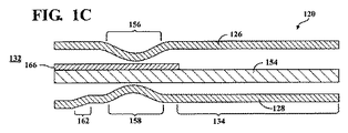
図1Cに、発明の別の局面に従って構築されるガスケットアセンブリ120を示し、以上で論じたのと同様の特徴を同定するのに100だけオフセットされる同じ参照番号を用いる。ガスケットアセンブリ120は、各々が少なくとも1つの一次封止ビード156,158を含む2つのガスケット層126,128を有する。第1の一次封止ビード156は、第1のガスケット層126から中間層154に向けて内向きに突出する。第1の一次封止ビード156に径方向に整列される第2の一次封止ビード158は、第2のガスケット層128から中間層154に向けて内向きに突出する。ストッパ層166は、第1のガスケット層126と中間層154との間に配設され、アパーチャ132からガスケット層126,128の外側領域134に径方向に延在する。発明のこの局面に従うと、二次封止ビード162は第2のガスケット層128から突出し、二次封止ビード162の屈曲部は一般的に中間層154から離れるように外向きに開く。
FIG. 1C shows a
図1Dに、発明の別の局面に従って構築されるガスケットアセンブリ220を示し、以上で論じたのと同様の特徴を同定するのに200だけオフセットされる同じ参照番号を用いる。ガスケットアセンブリ220は、各々が少なくとも1つの一次封止ビード256,258を含む2つのガスケット層226,228を有する。第1の一次封止ビード256は、第1のガスケット層226から中間層254に向けて内向きに突出する。第1の一次封止ビード256に径方向に整列される第2の一次封止ビード258は、第2のガスケット層228から中間層254に向けて内向きに突出する。ストッパ層266は、第1のガスケット層226と中間層254との間に配設され、アパーチャ232からガスケット層226,228の外側領域234に径方向に延在する。発明のこの局面に従うと、二次封止ビード262は第1のガスケット層226および第2のガスケット層228の両方から突出し、各々の二次封止ビード262の屈曲部は全般的に、中間層254から離れるように外向きに開く。
FIG. 1D shows a
図2Aに、発明の別の局面に従って構築されるガスケットアセンブリ320を示し、以上で論じたのと同様の特徴を同定するのに300だけオフセットされる同じ参照番号を用いる。ガスケットアセンブリ320は、各々が少なくとも1つの一次封止ビード356,358を含む2つのガスケット層326,328を有する。ストッパ層366は第1のガスケット層326と第2のガスケット層328との間に配設され、アパーチャ332からガスケット層326,328の外側領域334に径方向に延在する。第1の一次封止ビード356は、ストッパ層366から離れるように第1のガスケット層326から外向きに突出する。第1の一次封止ビード356に径方向に整列される第2の一次封止ビード358は、ストッパ層366から離れるように第2のガスケット層328から外向きに突出する。発明のこの局面に従うと、二次封止ビード362は第1のガスケット層326および第2のガスケット層328の両方から突出し、各々の二次封止ビード362の屈曲部は全般的に、ストッパ層366から離れるように外向きに開く。
FIG. 2A shows a
図2Bに、発明の別の局面に従って構築されるガスケットアセンブリ420を示し、以上で論じたのと同様の特徴を同定するのに400だけオフセットされる同じ参照番号を用いる。ガスケットアセンブリ420は、各々が少なくとも1つの一次封止ビード456,458を含む2つのガスケット層426,428を有する。ストッパ層466は、第1のガスケット層426と第2のガスケット層428との間に配設され、アパーチャ432からガスケット層426,428の外側領域434に径方向に延在する。第1の一次封止ビード456は、ストッパ層466から離れるように第1のガスケット層426から外向きに突出する。第1の一次封止ビード456に径方向に整列される第2の一次封止ビード458は、ストッパ層466から離れるように第2のガスケット層428から外向きに突出する。発明のこの局面に従うと、二次封止ビード462は第1のガスケット層426から突出し、二次封止ビード462の屈曲部は全般的に、ストッパ層466から離れるように外向きに開く。
FIG. 2B shows a
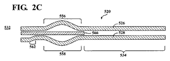
図2Cに、発明の別の局面に従って構築されるガスケットアセンブリ520を示し、以上で論じたのと同様の特徴を同定するのに500だけオフセットされる同じ参照番号を用いる。ガスケットアセンブリ520は、各々が少なくとも1つの一次封止ビード556,558を含む2つのガスケット層526,528を有する。ストッパ層566は、第1のガスケット層526と第2のガスケット層528との間に配設され、アパーチャ532からガスケット層526,528の外側領域534に径方向に延在する。第1の一次封止ビード556は、ストッパ層566から離れるように第1のガスケット層526から外向きに突出する。第1の一次封止ビード556に径方向に整列される第2の一次封止ビード558は、ストッパ層566から離れるように第2のガスケット層528から外向きに突出する。発明のこの局面に従うと、二次封止ビード562は第2のガスケット層528から突出し、二次封止ビード562の屈曲部は全般的に、ストッパ層566から離れるように外向きに開く。
FIG. 2C shows a
図2Dに、発明の別の局面に従って構築されるガスケットアセンブリ620を示し、以上で論じたのと同様の特徴を同定するのに600だけオフセットされる同じ参照番号を用いる。ガスケットアセンブリ620は、各々が少なくとも1つの一次封止ビード656,658を含む2つのガスケット層626,628を有する。ストッパ層666は、第1のガスケット層626と第2のガスケット層628との間に配設され、アパーチャ632からガスケット層626,628の外側領域634に径方向に延在する。第1の一次封止ビード656は、第1のガスケット層626からストッパ層666に向けて内向きに突出する。第1の一次封止ビード656に径方向に整列される第2の一次封止ビード658は、第2のガスケット層628からストッパ層666に向けて内向きに突出する。発明のこの局面に従うと、二次封止ビード662は第1のガスケット層626および第2のガスケット層628の両方から突出し、各々の二次封止ビード662の屈曲部は全般的に、ストッパ層666に向けて内向きに開く。
FIG. 2D shows a
図3を参照すると、図1Dに描かれる配置に従って構築されるガスケットアセンブリ220が内燃機関の中に設置されて示される。アパーチャ232は一般的に、内燃機関中のシリンダボアの載置に重なる区域に対応するが、排気口、冷却チャネル、締結具を受けるためのねじ穴、ならびにシリンダヘッド224および/またはエンジンブロック222中の他の空隙に重なる区域にも対応し得ることを認めるべきである。エンジンブロック222は、シリンダヘッド224に隣接するデッキ面236と、内側シリンダ壁240を形成するシリンダ中に配設される少なくとも1つのスリーブ238とをさらに含んでもよい。この構成に従うと、ガスケット層226,228の内側端縁230は、スリーブ238によって形成される内側シリンダ壁240に径方向に整列される。第1のガスケット層226の外側面248は内燃機関のシリンダヘッド224に嵌まり合い、第2のガスケット層228の外側面248は、内燃機関のエンジンブロック222に嵌まり合う。より具体的には、第2のガスケット層228の外側面248は、エンジンブロック222のデッキ面236に嵌まり合ってもよい。
Referring to FIG. 3, a
図4Aおよび図4Bを参照して、先行技術のガスケットアセンブリ20が示される。ピストン42との直接の接触からシリンダを遮蔽するのにスリーブ38を利用する典型的な内燃機関で、内燃機関の熱サイクルは、スリーブ38をエンジンブロック22に対して軸方向に伸縮させる。これは、スリーブ38がエンジンブロック22を形成する材料とは異なる金属からなる場合に特に当てはまる。というのも、異なる金属(たとえば、アルミニウムと鋼)は熱膨張性が異なるからである。スリーブ38の膨張は先行技術のガスケットアセンブリ20を壊し、これにより、そのようなアセンブリ20を永久的に変形させる可能性がある。ガスケットアセンブリ20の永久的な変形は問題である。なぜなら、ガスケットアセンブリ20の弾性の一部が失われて、その結果、封止能力が劣ってしまうからである。図4Bに示されるように、スリーブ38がより低い温度に晒される場合、スリーブ38は軸方向に縮むことがあるため、露出端44はシリンダボアの中に後退し、スリーブ38の露出端44とガスケットアセンブリ20との間に間隙が残り、小さな燃焼ガスの漏れが生じてしまう。
4A and 4B, a prior
図5Aおよび図5Bを参照すると、図2Cに描かれる配置に従って構築されるガスケットアセンブリ520が例示的な内燃機関の伸縮するスリーブ538と相互作用して示される。本明細書中に開示される特定的な構造は、これが熱負荷を経る際に、スリーブ538の伸縮により十分に対応することができるガスケットアセンブリ520をもたらす。より具体的には、一次封止ビード556,558および二次封止ビード562の両方に重なり合う関係にストッパ層を置くことにより、膨張するスリーブ538によってガスケットアセンブリ520に加わる圧縮力が両方の封止ビード556,558,562の全径方向長さにわたって分散される。
Referring to FIGS. 5A and 5B, a
図5Aおよび図5Bに示されるように、少なくとも1つのスリーブ538は、形状がほぼ筒状であり、エンジンブロック522とピストン542との間にシリンダボアの中に配設される。スリーブ538は、エンジンブロック522に用いられるのとは異なる金属または合金からなってもよい。たとえば、エンジンブロック522はアルミニウムからなってもよく、スリーブ538は鋼または鋳鉄からなってもよい。以前に注記したように、これらの金属は熱膨張率が異なる。図5Aおよび図5Bに示されるように、スリーブ538が熱負荷を経てシリンダボアに対して軸方向に伸縮する状況がエンジンの動作の間に起こることがある。いずれの伸縮もシリンダブロックのデッキ面536に隣接するスリーブ538の露出端544の軸方向移動に限られるように、スリーブ538がシリンダボア中に制約されることを認めるべきである。たとえば、スリーブ538が高温に晒されると、スリーブ538は、露出端544がエンジンブロック522のデッキ面536から突出するように軸方向に膨張することがある。
As shown in FIGS. 5A and 5B, the at least one
図5Aに示されるように、封止ビード556,558,562に対するストッパ層566の特定的な載置により、スリーブ538が高温下で膨張するにつれてスリーブ538が封止ビード556,558,562のうち1つを壊すまたは永久的に変形させるのを防止する。図5Bに示されるように、内側端縁530に隣接するガスケットアセンブリ520の弾性が保全され、スリーブ538がより低い動作温度によって後退すると、二次封止ビード562は圧縮されていない状態に戻る。応じて、スリーブ538とガスケットアセンブリ520との間には間隙が生じず、小さな気体の漏れが排除される。このように、ストッパ層566は、ガスケット層526,528の内側端縁530に隣接する増大したガスケット弾性および性能を提供する。
As shown in FIG. 5A, the specific placement of the
図6を参照して、ガスケットアセンブリ20の内側端縁30は、側方部分52によって離間される限定された周方向部分の1対の軸方向に整列される架橋部分50を含んでもよい。ともに、架橋部分50および内側端縁30の側方部分52は、全体がアパーチャ32に外接する。たとえば、ガスケットアセンブリ20を見下ろすと、アパーチャ32は、軸方向に整列される架橋部分50によって左右で、ならびに側方部分52によって頂部および底部で境界決めされてもよい。少なくとも1つのアパーチャ32は、隣接する架橋部分50によって離間される、複数の軸方向に整列されるアパーチャ32でもあってもよい。この構成に従うと、架橋部分50は隣接するアパーチャ32同士の間に配設される。ガスケットアセンブリ20は典型的に架橋部分50でより大きな熱および圧力に晒され、これらの上昇した動作特性はしばしば、架橋部分50の区域での封止の問題およびガスケットの破損に繋がってしまう。さらに、架橋部分50中の隣接するスリーブ38同士の間の間隔が小さいため、スリーブ38の熱負荷によって生じる、デッキ面36でのいずれの高低差も架橋部分50で誇張されてしまう。応じて、より大きな封止能力を有するガスケットアセンブリ20に対する必要性が架橋部分50において大きくなる。二次封止ビード62は、アパーチャ32の周りで周方向に延在しかつアパーチャ32を囲繞してもよい。これに代えて、二次封止ビード62は、ガスケットアセンブリ20の軸方向に整列された架橋部分50のみに沿って延在する限定された周方向部分を有してもよい。図6に見られるように、アパーチャ32は、各々が二次封止ビード62を特徴とする架橋部分50によっていずれかの側で側方に位置してもよい。この場合、二次封止ビード62の限定された周方向の延在は、架橋部分50と同一の広がりを持ち、かつ内側端縁30の周方向部分の一部のみに等しい。
With reference to FIG. 6, the
明らかに、以上の教示に照らして本発明の多数の修正例および変形例が可能であり、添付の請求項の範囲内にありつつ、具体的に説明される以外のやり方で実践されてもよい。これらの先行する記載は、発明の新規性がその有用性を働かせるいずれの組合せもカバーすると解釈されるべきである。装置請求項における語「前記」の使用は、請求項のカバー範囲に含まれることが意味される積極的な記載である前置語を参照する一方で、語「当該」は、請求項のカバー範囲に含まれることが意味されない語に先立つものである。さらに、請求項中の同じ番号は単に便宜上のものであり、いずれの態様でも限定的と読まれてはならない。 Obviously, many modifications and variations of the present invention are possible in light of the above teachings, which may be practiced otherwise than as specifically described while remaining within the scope of the appended claims. . These preceding descriptions should be construed to cover any combination in which the novelty of the invention exerts its utility. The use of the word “said” in a device claim refers to a prefix that is an active statement meant to be included in the scope of the claim, while the word “related” It precedes words that are not meant to be included in the range. Moreover, the same reference numerals in the claims are merely for convenience and should not be read as limiting in any way.
Claims (12)
少なくとも1つのアパーチャに外接する内側端縁と前記アパーチャから径方向に離間される外側領域とを有する少なくとも1つのガスケット層と、
前記内側端縁と前記外側領域との間に前記ガスケット層に沿って配設される少なくとも1つの一次封止ビードとを備え、前記一次封止ビードは前記アパーチャの周りに周方向にかつ第1の径方向長さに沿って径方向に延在し、さらに
前記一次封止ビードと前記内側端縁との間に前記ガスケット層に沿って配設される少なくとも1つの二次封止ビードを備え、前記二次封止ビードは第2の径方向長さに沿って延在し、さらに
前記ガスケット層の少なくとも一部に隣接しかつ前記外側領域から前記ガスケット層の前記内側端縁に径方向に延在して前記一次封止ビードの前記第1の径方向長さおよび前記二次封止ビードの前記第2の径方向長さに全体的に重なって、前記ガスケット層の前記内側端縁に隣接して増大したガスケット弾性を与えるストッパ層を備え、
前記ガスケット層の前記内側端縁は、側方部分によって離間される限定された周方向部分の1対の軸方向に整列される架橋部分を含み、前記少なくとも1つの二次封止ビードは、全体が前記架橋部分に沿って延在する限定された周方向部分を有する、アセンブリ。 A gasket assembly,
At least one gasket layer having an inner edge circumscribing at least one aperture and an outer region radially spaced from the aperture;
At least one primary sealing bead disposed along the gasket layer between the inner edge and the outer region, the primary sealing bead circumferentially around the aperture and first And at least one secondary sealing bead extending along the gasket layer and extending between the primary sealing bead and the inner edge. The secondary sealing bead extends along a second radial length and is adjacent to at least a portion of the gasket layer and radially from the outer region to the inner edge of the gasket layer. Extending over and overlapping the first radial length of the primary sealing bead and the second radial length of the secondary sealing bead to the inner edge of the gasket layer Adjacent threads providing increased gasket resilience Tsu with the path layer,
The inner edge of the gasket layer includes a pair of axially aligned bridging portions of a limited circumferential portion spaced by side portions, and the at least one secondary sealing bead is entirely Having a limited circumferential portion extending along said bridging portion .
Applications Claiming Priority (3)
| Application Number | Priority Date | Filing Date | Title |
|---|---|---|---|
| US13/804,853 | 2013-03-14 | ||
| US13/804,853 US9939066B2 (en) | 2013-03-14 | 2013-03-14 | Elastic sealing member radially inwardly of primary sealing bead |
| PCT/US2014/019712 WO2014158732A1 (en) | 2013-03-14 | 2014-03-01 | Small elastic sealing feature inside of main combustion sealing embossment |
Related Child Applications (1)
| Application Number | Title | Priority Date | Filing Date |
|---|---|---|---|
| JP2018143572A Division JP6657334B2 (en) | 2013-03-14 | 2018-07-31 | Small elastic sealing feature inside the main combustion sealing embossing |
Publications (3)
| Publication Number | Publication Date |
|---|---|
| JP2016517497A JP2016517497A (en) | 2016-06-16 |
| JP2016517497A5 JP2016517497A5 (en) | 2017-02-23 |
| JP6381624B2 true JP6381624B2 (en) | 2018-08-29 |
Family
ID=50336536
Family Applications (2)
| Application Number | Title | Priority Date | Filing Date |
|---|---|---|---|
| JP2016500526A Expired - Fee Related JP6381624B2 (en) | 2013-03-14 | 2014-03-01 | Gasket assembly |
| JP2018143572A Expired - Fee Related JP6657334B2 (en) | 2013-03-14 | 2018-07-31 | Small elastic sealing feature inside the main combustion sealing embossing |
Family Applications After (1)
| Application Number | Title | Priority Date | Filing Date |
|---|---|---|---|
| JP2018143572A Expired - Fee Related JP6657334B2 (en) | 2013-03-14 | 2018-07-31 | Small elastic sealing feature inside the main combustion sealing embossing |
Country Status (7)
| Country | Link |
|---|---|
| US (1) | US9939066B2 (en) |
| EP (1) | EP2971874B1 (en) |
| JP (2) | JP6381624B2 (en) |
| KR (1) | KR20150130417A (en) |
| CN (1) | CN105190129B (en) |
| BR (1) | BR112015023099A2 (en) |
| WO (1) | WO2014158732A1 (en) |
Families Citing this family (7)
| Publication number | Priority date | Publication date | Assignee | Title |
|---|---|---|---|---|
| US10634251B2 (en) * | 2014-08-20 | 2020-04-28 | Tenneca Inc. | Multi-layer gasket assembly |
| CN105351110A (en) * | 2015-12-04 | 2016-02-24 | 广西玉柴机器股份有限公司 | Cylinder head gasket |
| US9964068B2 (en) | 2016-02-25 | 2018-05-08 | Ford Global Technologies, Llc | Head gasket for an internal combustion engine |
| DE202016106106U1 (en) | 2016-10-31 | 2018-02-12 | Reinz-Dichtungs-Gmbh | Flat gasket and internal combustion engine |
| JP6408659B1 (en) * | 2017-07-18 | 2018-10-17 | 石川ガスケット株式会社 | gasket |
| US11635143B2 (en) * | 2019-10-14 | 2023-04-25 | Dana Automotive Systems Group, Llc | Multi-layer gasket with improved fatigue resistance |
| US11585441B2 (en) * | 2020-11-20 | 2023-02-21 | Dana Automotive Systems Group, Llc | Laser profiled gasket and method for manufacturing said gasket |
Family Cites Families (35)
| Publication number | Priority date | Publication date | Assignee | Title |
|---|---|---|---|---|
| JPH0861506A (en) * | 1994-08-19 | 1996-03-08 | Nippon Gasket Co Ltd | Cylinder head gasket of metal |
| JPH08121596A (en) | 1994-10-21 | 1996-05-14 | Nok Corp | Gasket |
| JP3129626B2 (en) * | 1995-02-06 | 2001-01-31 | 日本ガスケット株式会社 | Metal gasket |
| JP3230959B2 (en) * | 1995-09-05 | 2001-11-19 | 日本ガスケット株式会社 | Metal gasket |
| US5924700A (en) | 1996-03-12 | 1999-07-20 | Nok Corporation | Gasket |
| DE69826998T2 (en) | 1998-08-25 | 2005-10-13 | Federal-Mogul Operations Italy S.R.L. | Steel cylinder head gasket for motor vehicles |
| JP2001241551A (en) | 2000-02-25 | 2001-09-07 | Taiho Kogyo Co Ltd | Cylinder head gasket |
| JP4631128B2 (en) | 2000-04-17 | 2011-02-16 | 大豊工業株式会社 | Cylinder head gasket |
| DE20121984U1 (en) | 2000-06-15 | 2003-11-27 | Reinz-Dichtungs-Gmbh & Co. Kg | gasket |
| JP3753413B2 (en) | 2000-08-07 | 2006-03-08 | 石川ガスケット株式会社 | Multi-cylinder head gasket |
| DE10101604B4 (en) | 2001-01-16 | 2005-02-17 | Federal-Mogul Sealing Systems Gmbh | Metallic cylinder head gasket |
| JP3885959B2 (en) | 2001-03-07 | 2007-02-28 | 日本メタルガスケット株式会社 | Metal gasket |
| DE10200544B4 (en) | 2002-01-09 | 2005-04-28 | Federal Mogul Sealing Sys Spa | Cylinder head gasket to compensate for local subsidence in the area of the compression limiter |
| US6899340B2 (en) | 2002-02-15 | 2005-05-31 | Dana Corporation | MLS gasket with bore edge stopper bead |
| US6962345B2 (en) | 2002-02-15 | 2005-11-08 | Dana Corporation | MLS gasket with bore edge stopper bead |
| JP2004019668A (en) | 2002-06-12 | 2004-01-22 | Ishino Gasket Kogyo Kk | Bead |
| DE10310014B4 (en) | 2003-02-28 | 2009-09-10 | Reinz-Dichtungs-Gmbh | Cylinder head gasket |
| CA2477342A1 (en) | 2003-08-28 | 2005-02-28 | Freudenberg-Nok General Partnership | Improved sealing gasket with flexible stopper |
| US7234705B2 (en) | 2003-08-28 | 2007-06-26 | Freudenberg-Nok General Partnership | Sealing gasket with flexible stopper |
| JP3960383B2 (en) | 2003-10-30 | 2007-08-15 | 石川ガスケット株式会社 | Cylinder head gasket |
| DE102004012905A1 (en) | 2004-03-17 | 2005-10-13 | Elringklinger Ag | Cylinder head gasket |
| ATE420721T1 (en) * | 2004-08-05 | 2009-01-15 | Saudi Basic Ind Corp | METHOD USING A HEAT EXCHANGER COATED WITH A CATALYST |
| US7374177B2 (en) * | 2004-09-21 | 2008-05-20 | Federal-Mogul World Wide, Inc. | Enhanced multilayer metal gasket |
| US7407164B2 (en) | 2004-12-21 | 2008-08-05 | Elringklinger Ag | Gasket |
| EP1985896B1 (en) | 2007-04-24 | 2012-12-12 | REINZ-Dichtungs-GmbH | Metal flat gasket |
| JP4914792B2 (en) | 2007-09-07 | 2012-04-11 | 日本リークレス工業株式会社 | Metal gasket |
| US8100409B2 (en) * | 2007-09-11 | 2012-01-24 | Federal-Mogul World Wide, Inc. | Metallic cylinder head gasket |
| JP4536765B2 (en) | 2007-10-12 | 2010-09-01 | 石川ガスケット株式会社 | Metal gasket |
| JP2009097529A (en) * | 2007-10-12 | 2009-05-07 | Ishikawa Gasket Co Ltd | Metal laminated gasket |
| US8632077B2 (en) | 2008-02-13 | 2014-01-21 | Federal-Mogul Corporation | Multilayer static gasket with bead compression limiter |
| EP2325529A4 (en) | 2008-09-18 | 2016-03-16 | Nippon Gasket Kk | Cylinder head gasket |
| JP5344222B2 (en) * | 2008-12-26 | 2013-11-20 | 日本ガスケット株式会社 | Seal structure of oil pit in cylinder head gasket |
| DE102009008791A1 (en) * | 2009-02-13 | 2010-09-16 | Federal-Mogul Sealing Systems Gmbh | Flat seals with additional sealing element |
| US10006403B2 (en) * | 2009-06-24 | 2018-06-26 | Federal-Mogul Llc | Cylinder head gasket |
| EP2671005B1 (en) | 2011-02-01 | 2016-01-06 | Federal-Mogul Corporation | Multilayer static gasket with secondary compression limiter |
-
2013
- 2013-03-14 US US13/804,853 patent/US9939066B2/en not_active Expired - Fee Related
-
2014
- 2014-03-01 JP JP2016500526A patent/JP6381624B2/en not_active Expired - Fee Related
- 2014-03-01 CN CN201480023277.4A patent/CN105190129B/en not_active Expired - Fee Related
- 2014-03-01 WO PCT/US2014/019712 patent/WO2014158732A1/en active Application Filing
- 2014-03-01 BR BR112015023099A patent/BR112015023099A2/en not_active IP Right Cessation
- 2014-03-01 EP EP14711378.1A patent/EP2971874B1/en active Active
- 2014-03-01 KR KR1020157028075A patent/KR20150130417A/en not_active Application Discontinuation
-
2018
- 2018-07-31 JP JP2018143572A patent/JP6657334B2/en not_active Expired - Fee Related
Also Published As
| Publication number | Publication date |
|---|---|
| BR112015023099A2 (en) | 2017-07-18 |
| KR20150130417A (en) | 2015-11-23 |
| EP2971874A1 (en) | 2016-01-20 |
| US9939066B2 (en) | 2018-04-10 |
| CN105190129A (en) | 2015-12-23 |
| JP6657334B2 (en) | 2020-03-04 |
| EP2971874B1 (en) | 2019-10-30 |
| US20140265156A1 (en) | 2014-09-18 |
| CN105190129B (en) | 2018-04-03 |
| JP2016517497A (en) | 2016-06-16 |
| WO2014158732A1 (en) | 2014-10-02 |
| JP2018200104A (en) | 2018-12-20 |
Similar Documents
| Publication | Publication Date | Title |
|---|---|---|
| JP6657334B2 (en) | Small elastic sealing feature inside the main combustion sealing embossing | |
| US8246053B2 (en) | Exhaust manifold gasket with spring steel embossed metal and graphite insulator | |
| KR101011509B1 (en) | Metal Gasket | |
| JP4137116B2 (en) | Cylinder head gasket | |
| JP6246797B2 (en) | Metal gasket | |
| KR20130008027A (en) | Multilayer gasket with labyrinth stopper | |
| KR20080076748A (en) | Laminated gasket | |
| JP5136808B2 (en) | Cylinder head gasket and manufacturing method thereof | |
| EP3158235B1 (en) | Cylinder head gasket with compression limiter and full bead loading | |
| CN102953863B (en) | Coolant seals part and manifold gasket component | |
| EP1363751A2 (en) | Metal gasket with cold formed stopper | |
| JP4056503B2 (en) | Metal gasket | |
| US9869271B2 (en) | Cylinder head gasket | |
| US10982769B2 (en) | Flat gasket and internal combustion engine | |
| JP6890548B2 (en) | Sealed structure between cylinder block and cylinder head | |
| JP2009185865A (en) | Piston ring, and piston and engine using the same | |
| JP4258980B2 (en) | Engine seal structure | |
| JP2008223581A (en) | Metal gasket | |
| KR101283033B1 (en) | Cylinder head gasket | |
| JP2002098232A (en) | Seal structure of engine, and gasket |
Legal Events
| Date | Code | Title | Description |
|---|---|---|---|
| A521 | Request for written amendment filed |
Free format text: JAPANESE INTERMEDIATE CODE: A523 Effective date: 20170120 |
|
| A621 | Written request for application examination |
Free format text: JAPANESE INTERMEDIATE CODE: A621 Effective date: 20170120 |
|
| A977 | Report on retrieval |
Free format text: JAPANESE INTERMEDIATE CODE: A971007 Effective date: 20171109 |
|
| A131 | Notification of reasons for refusal |
Free format text: JAPANESE INTERMEDIATE CODE: A131 Effective date: 20171128 |
|
| A521 | Request for written amendment filed |
Free format text: JAPANESE INTERMEDIATE CODE: A523 Effective date: 20180228 |
|
| TRDD | Decision of grant or rejection written | ||
| A01 | Written decision to grant a patent or to grant a registration (utility model) |
Free format text: JAPANESE INTERMEDIATE CODE: A01 Effective date: 20180703 |
|
| A61 | First payment of annual fees (during grant procedure) |
Free format text: JAPANESE INTERMEDIATE CODE: A61 Effective date: 20180731 |
|
| R150 | Certificate of patent or registration of utility model |
Ref document number: 6381624 Country of ref document: JP Free format text: JAPANESE INTERMEDIATE CODE: R150 |
|
| LAPS | Cancellation because of no payment of annual fees |