EP3862251A1 - Vehicle pillar structure - Google Patents
Vehicle pillar structure Download PDFInfo
- Publication number
- EP3862251A1 EP3862251A1 EP21152188.5A EP21152188A EP3862251A1 EP 3862251 A1 EP3862251 A1 EP 3862251A1 EP 21152188 A EP21152188 A EP 21152188A EP 3862251 A1 EP3862251 A1 EP 3862251A1
- Authority
- EP
- European Patent Office
- Prior art keywords
- pillar
- vehicle
- roof
- width direction
- vertical
- Prior art date
- Legal status (The legal status is an assumption and is not a legal conclusion. Google has not performed a legal analysis and makes no representation as to the accuracy of the status listed.)
- Granted
Links
Images


Classifications
-
- B—PERFORMING OPERATIONS; TRANSPORTING
- B62—LAND VEHICLES FOR TRAVELLING OTHERWISE THAN ON RAILS
- B62D—MOTOR VEHICLES; TRAILERS
- B62D25/00—Superstructure or monocoque structure sub-units; Parts or details thereof not otherwise provided for
- B62D25/04—Door pillars ; windshield pillars
-
- B—PERFORMING OPERATIONS; TRANSPORTING
- B62—LAND VEHICLES FOR TRAVELLING OTHERWISE THAN ON RAILS
- B62D—MOTOR VEHICLES; TRAILERS
- B62D31/00—Superstructures for passenger vehicles
- B62D31/02—Superstructures for passenger vehicles for carrying large numbers of passengers, e.g. omnibus
Definitions
- the present invention relates to a vehicle pillar structure.
- vehicle pillars each including a first pillar and a second pillar arranged away from each other in a front-and-rear direction of a vehicle are arranged at a front part of the vehicle.
- a transparent window member is interposed between the first pillar and the second pillar to cover an opening defined by the first pillar and the second pillar. Therefore, an occupant seated on a driver's seat can view the outside of the vehicle through the transparent window member at the opening of the vehicle pillar. Thus, the visibility of the occupant is improved.
- the vehicle pillar has a straight shape, and is inclined toward the rear of the vehicle with decreasing distance to the top of the vehicle. Therefore, the distance between a front windshield glass and an occupant in a vehicle cabin decreases as the distance to the top of the vehicle decreases from any part of the vehicle pillar.
- the related art has room for improvement toward a wider vehicle cabin space so that the occupant in the vehicle cabin has a sense of openness to a higher degree.
- the present invention provides a vehicle pillar structure with which the visibility of an occupant can be improved and a vehicle cabin space can be increased.
- a vehicle pillar structure includes a vehicle pillar and a transparent window member.
- the vehicle pillar includes a first pillar and a second pillar.
- the first pillar extends along an outer end of a windshield glass in a width direction of a vehicle.
- the second pillar is disposed away from the first pillar by a predetermined distance in a front-and-rear direction of the vehicle.
- An outside of the vehicle is viewable through the transparent window member.
- the transparent window member is interposed between the first pillar and the second pillar, and covers an opening defined by the first pillar and the second pillar.
- the vehicle pillar has a curved shape defined by a straight portion and a curved portion.
- the straight portion extends in a vertical direction of the vehicle in side view.
- the curved portion is curved from an upper end of the straight portion, and extends in the front-and-rear direction of the vehicle.
- an occupant in a vehicle cabin at a front part or a rear part of the vehicle can view the outside of the vehicle through the transparent window member at the opening of the vehicle pillar. Therefore, a blind spot of the vehicle pillar is reduced for the occupant in the vehicle cabin. Thus, the visibility is improved.
- the vehicle pillar has the curved shape defined by the straight portion extending in the vertical direction of the vehicle in side view, and the curved portion curved from the upper end of the straight portion and extending in the front-and-rear direction of the vehicle. Since the upper part of the vehicle pillar extends in the front-and-rear direction of the vehicle by the curved portion, the vehicle cabin space can be increased as compared to a vehicle pillar inclined in a straight shape in side view.
- the curved portion may be integrated with a roof side rail, the roof side rail constituting a framework of a roof serving as a ceiling of a vehicle cabin of the vehicle and disposed at an outer end of the roof in the width direction of the vehicle to extend in the front-and-rear direction of the vehicle.
- the vehicle pillar is integrated with the roof side rail. Therefore, a load input to the vehicle pillar in the event of, for example, front-end or rear-end collision of the vehicle can efficiently be transmitted to the roof side rail and the roof.
- a first reinforcement member that couples the first pillar and the second pillar together may be provided at a boundary between the straight portion and the curved portion.
- the vehicle pillar is curved at the boundary between the straight portion and the curved portion. Therefore, a stress caused by the load input in the event of front-end or rear-end collision of the vehicle concentrates on this boundary.
- the first reinforcement member that couples the first pillar and the second pillar together is provided at the boundary between the straight portion and the curved portion. Therefore, the vehicle pillar is structured such that the first reinforcement member effectively reinforces the part where the stress concentrates in the event of front-end or rear-end collision of the vehicle. Thus, deformation of the vehicle pillar is suppressed in the event of front-end or rear-end collision of the vehicle.
- one end of a roof header may be coupled to a boundary between the straight portion and the curved portion.
- the roof header constitutes a framework of the roof serving as a ceiling of a vehicle cabin of the vehicle, and is disposed at an outer end of the roof in the front-and-rear direction of the vehicle to extend in the width direction of the vehicle.
- the vehicle pillar is effectively reinforced by coupling the roof header to the part of the vehicle pillar where the stress concentrates in the event of front-end or rear-end collision of the vehicle.
- the deformation of the vehicle pillar is suppressed in the event of front-end or rear-end collision of the vehicle.
- a middle part of the first pillar and a lower part of the second pillar may be coupled together by a second reinforcement member.
- the lower part of the second pillar may be disposed so as to be offset outward in the width direction of the vehicle with respect to the middle part of the first pillar.
- the load input to the lower part of the vehicle pillar in the event of front-end or rear-end collision of the vehicle is distributed to the first pillar and the second pillar via the second reinforcement member.
- the lower part of the second pillar is disposed so as to be offset outward in the width direction of the vehicle with respect to the middle part of the first pillar. Therefore, the load input to the vehicle pillar in the event of front-end or rear-end collision of the vehicle can be distributed outward in the width direction of the vehicle.
- deformation at the front or rear of the vehicle is suppressed in the event of front-end or rear-end collision of the vehicle.
- a framework member may be disposed on an inner side of the vehicle pillar in the front-and-rear direction of the vehicle.
- the framework member includes a vertical pillar portion extending in the vertical direction of the vehicle.
- the vertical pillar portion may constitute a side part of the framework member in the width direction of the vehicle.
- An upper end of the first pillar and an upper end of the second pillar may be coupled to the vertical pillar portion.
- the load input to the vehicle pillar in the event of front-end or rear-end collision of the vehicle is transmitted to the framework member disposed on the inner side in the front-and-rear direction of the vehicle.
- the rigidity and strength of the vehicle pillar can be increased.
- a lower part of the second pillar may be coupled to the vertical pillar portion of the framework member via a third reinforcement member.
- the load input to the lower part of the second pillar of the vehicle pillar in the event of front-end or rear-end collision of the vehicle is transmitted to the vertical pillar portion of the framework member via the third reinforcement member.
- deformation of the second pillar and deformation at the front or rear of the vehicle are suppressed in the event of front-end or rear-end collision of the vehicle.
- the framework member may have an annular shape when viewed in the front-and-rear direction of the vehicle.
- the annular shape may be defined by a pair of the vertical pillar portions and a reinforcement portion that couples upper ends of the pair of the vertical pillar portions together in the width direction of the vehicle and couples lower ends of the pair of the vertical pillar portions together in the width direction of the vehicle.
- the framework member has the annular shape when viewed in the front-and-rear direction of the vehicle, and the rigidity and strength are increased.
- the rigidity and strength of the vehicle pillar can further be increased, thereby contributing to suppression of deformation in the event of front-end or rear-end collision of the vehicle.
- a sectional area of the curved portion may be larger than a sectional area of the straight portion.
- the vehicle pillar structure according to the present invention has an advantageous effect that the visibility of the occupant can be improved and the vehicle cabin space can be increased.
- a vehicle 10 to which a vehicle pillar structure according to an embodiment is applied is described below with reference to FIG. 1 to FIG. 4 .
- An arrow FR shown as appropriate in the drawings indicates a front side of the vehicle.
- An arrow UP shown as appropriate in the drawings indicates a top side of the vehicle.
- An arrow LH shown as appropriate in the drawings indicates a left side of the vehicle.
- terms "front”, “rear”, “up”, “down”, “right”, and “left” as used in the following description mean the front and rear in a front-and-rear direction of the vehicle, the top and bottom in a vertical direction of the vehicle, and the right and left in a case where the vehicle is oriented in a traveling direction.
- the vehicle 10 includes a frame structure (not illustrated) and a body 12.
- the frame structure is arranged at a lower part of the vehicle 10 to serve as a framework member at the lower part of the vehicle.
- the body 12 is fixed onto the frame structure.
- the body 12 is formed into a substantially rectangular parallelepiped shape that is long in the front-and-rear direction of the vehicle.
- the body 12 includes a pair of right and left side walls 12A, a floor 12B, and a roof 12C.
- the floor 12B is interposed between the side walls 12A in a width direction of the vehicle to serve as a floor surface of a vehicle cabin 14.
- the roof 12C serves as a ceiling of the vehicle cabin 14.
- a vehicle seat (not illustrated) is provided as a driver's seat in the vehicle cabin 14 on a front side of the vehicle and at a center in the width direction of the vehicle.
- a front windshield glass 22 (hereinafter referred to as "Fr glass 22") is provided at a front part of the vehicle cabin 14 to cover an opening 20 defined at the front of the vehicle 10.
- the Fr glass 22 is a transparent window member fixed to the opening 20, and separates the inside and outside of the vehicle cabin 14.
- the thickness direction of the Fr glass 22 is the front-and-rear direction of the vehicle (substantial front-and-rear direction of the vehicle).
- the Fr glass 22 extends in the width direction and the vertical direction of the vehicle, and is slightly inclined toward the rear of the vehicle with decreasing distance to the top of the vehicle in side view.
- the Fr glass 22 corresponds to an example of a "windshield glass" of the present invention.
- the upper end of the Fr glass 22 is connected to a roof header 12C1 extending in the width direction of the vehicle to define an upper edge of the opening 20.
- the roof header 12C1 constitutes a part of a framework of the roof 12C, and is arranged at the front end of the roof 12C.
- the roof header 12C 1 is a reinforcement member whose vertical sectional shape is a closed sectional shape, and extends along the width direction of the vehicle.
- the lower end of the Fr glass 22 is connected to a cowl (reference symbol is omitted) extending in the width direction of the vehicle to define a lower edge of the opening 20.
- the Fr glass 22 has a constant thickness, and has a gently curved shape so that a middle part of the Fr glass 22 in the width direction of the vehicle projects to the front side of the vehicle.
- a pair of right and left pillars 30 serving as vehicle pillars is provided on an outer side of the Fr glass 22 in the width direction of the vehicle.
- Each of the right and left pillars 30 has a curved shape having a curved part above the middle in its extending direction and projecting to the front side and the top side of the vehicle in side view.
- the lower part of the pillar 30 is a straight portion 30A.
- the straight portion 30A extends in the vertical direction of the vehicle (substantial vertical direction of the vehicle) along an outer end of the Fr glass 22 in the width direction of the vehicle.
- the upper part of the pillar 30 is a curved portion 30B.
- the curved portion 30B is gently curved from the upper end of the straight portion 30A, and extends substantially toward the rear of the vehicle (in the front-and-rear direction of the vehicle).
- the pillar 30 includes a first pillar 32 that constitutes a front part of the pillar 30, and a second pillar 40 that constitutes a rear part of the pillar 30.
- the pillar 30 further includes a first reinforcement member 52 and a second reinforcement member 54 that couple the first pillar 32 and the second pillar 40 together in the front-and-rear direction of the vehicle.
- the first pillar 32 has a curved shape having a curved part above the middle in its extending direction and projecting to the front side and the top side of the vehicle in side view.
- the first pillar 32 has a lower pillar portion 32A that constitutes the straight portion 30A of the pillar 30.
- the lower pillar portion 32A is constituted by a first outer pillar portion 34 and a first inner pillar portion 36 described later.
- the first pillar 32 also has an upper pillar portion 32B that constitutes the curved portion 30B of the pillar 30.
- the upper pillar portion 32B is constituted by the front end of a roof side rail 12C2 of the roof 12C. That is, the pillar 30 is integrated with the roof side rail 12C2 of the vehicle 10 such that the front end of the roof side rail 12C2 serves as a part of the first pillar 32.
- FIG. 4 is a plane sectional view illustrating a state in which the straight portion 30A of the pillar 30 is cut along a line IV-IV in FIG. 1 in a direction orthogonal to the extending direction (vertical direction of the vehicle).
- the sectional shape of the lower pillar portion 32A of the first pillar 32 is a closed sectional shape defined by the first outer pillar portion 34 and the first inner pillar portion 36.
- the first outer pillar portion 34 is made of a steel sheet, and has a substantially hat-shaped cross section open to the vehicle cabin 14.
- the first outer pillar portion 34 includes an outer side wall 34A and a pair of side walls 34B.
- the outer side wall 34A faces outside in the width direction of the vehicle.
- the side walls 34B extend inward in the width direction of the vehicle from the front end and the rear end of the outer side wall 34A, and face each other in the front-and-rear direction of the vehicle.
- a front flange 34C is formed at the distal end of the side wall 34B on the front side of the vehicle.
- a rear flange 34D is formed at the distal end of the side wall 34B on the rear side of the vehicle.
- the first inner pillar portion 36 is made of a steel sheet, and the sectional shape is substantially a crank shape.
- the first inner pillar portion 36 closes the opening of the first outer pillar portion 34 from the vehicle cabin 14 side.
- the front end and the rear end of the first inner pillar portion 36 are joined to the front flange 34C and the rear flange 34D of the first outer pillar portion 34, respectively.
- the lower pillar portion 32A of the first pillar 32 has a closed section structure defined by the first outer pillar portion 34 and the first inner pillar portion 36.
- a first outer panel 38 is arranged on a front side of the first outer pillar portion 34 in the front-and-rear direction of the vehicle to serve as an outer design surface of the lower pillar portion 32A.
- the first outer panel 38 substantially has a U-shape open to the rear of the vehicle, and covers the side wall 34B of the first outer pillar portion 34 on the front side of the vehicle from the outside of the vehicle cabin 14.
- First attachment flanges 38A are formed at the open end of the first outer panel 38 to extend away from each other.
- the first attachment flanges 38A are joined to the outer side wall 34A and the front flange 34C of the first outer pillar portion 34 from the outside of the vehicle cabin 14.
- a closed section structure is defined by the first outer pillar portion 34 and the first outer panel 38.
- the outer end of the Fr glass 22 in the width direction of the vehicle is joined, via a water-stop sealer 50, to the first attachment flange 38A joined to the front flange 34C.
- the front end of a transparent window member 60 described later in the front-and-rear direction of the vehicle is joined, via a water-stop sealer 50, to the first attachment flange 38A joined to the outer side wall 34A.
- the lower end of the lower pillar portion 32A is coupled to a bumper reinforcement 16 via a gusset (reference symbol is omitted).
- the bumper reinforcement 16 is a part of the frame structure serving as the framework member at the lower part of the vehicle, and extends in an elongated shape so that the width direction of the vehicle is a longitudinal direction. Both longitudinal ends of the bumper reinforcement 16 are fixed to the front ends (outer ends in the front-and-rear direction of the vehicle) of a pair of right and left side members 18 arranged away from each other in the width direction of the vehicle.
- Each side member 18 is a part of the frame structure serving as the framework member at the lower part of the vehicle, and the side member 18 extends in the front-and-rear direction of the vehicle that is a longitudinal direction.
- the bumper reinforcement 16 supports a front bumper (not illustrated) of the vehicle 10 from the rear side of the vehicle.
- the upper end of the lower pillar portion 32A is coupled to the front end of the roof side rail 12C2 (outer end in the front-and-rear direction of the vehicle) that constitutes the upper pillar portion 32B.
- the roof side rail 12C2 constitutes the framework of the roof 12C, and is arranged at the outer end of the roof 12C in the width direction of the vehicle to extend in the front-and-rear direction of the vehicle.
- the vertical sectional shape of the roof side rail 12C2 is a closed sectional shape, and the roof side rail 12C2 includes an outer roof side portion and an inner roof side portion (reference symbols are omitted).
- the outer roof side portion is arranged on an outer side in the width direction of the vehicle.
- the inner roof side portion is arranged on an inner side in the width direction of the vehicle with respect to the outer roof side portion.
- the sectional area of the closed section of the front end of the roof side rail 12C2 (upper pillar portion 32B) is set larger than the sectional area of the closed section of the lower pillar portion 32A. Therefore, in the first pillar 32, the upper pillar portion 32B near the ceiling of the vehicle cabin 14 is thicker than the lower pillar portion 32A near the height of a line of sight of an occupant in the vehicle cabin 14. Further, the sectional rigidity of the upper pillar portion 32B is set higher than the sectional rigidity of the lower pillar portion 32A.
- the lower pillar portion 32A and the roof side rail 12C2 are coupled together by joining their joint flanges (not illustrated).
- One end of the roof header 12C1 in its extending direction is coupled to the part where the lower pillar portion 32A and the upper pillar portion 32B are coupled together.
- a framework structure having an annular shape when viewed in the front-and-rear direction of the vehicle is formed at the front (and rear) of the vehicle 10 by the roof header 12C1, the bumper reinforcement 16, and the pair of right and left first pillars 32.
- the second pillar 40 that constitutes the rear part of the pillar 30 in the front-and-rear direction of the vehicle has a curved shape projecting to the front side and the top side of the vehicle in side view.
- the second pillar 40 includes a second outer pillar portion 42 and a second inner pillar portion 44.
- the second outer pillar portion 42 is arranged on an outer side in the width direction of the vehicle.
- the second inner pillar portion 44 is arranged on an inner side in the width direction of the vehicle with respect to the second outer pillar portion 42.
- the second pillar 40 is arranged away from the first pillar 32 by a predetermined distance in the front-and-rear direction of the vehicle. More specifically, the upper end of the second pillar 40 is arranged near the upper end of the first pillar 32. The distance between the second pillar 40 and the first pillar 32 gradually increases in the front-and-rear direction of the vehicle (substantial front-and-rear direction of the vehicle) with decreasing distance from the upper end to the lower end. The lower part of the second pillar 40 is offset outward in the width direction of the vehicle with respect to the middle part of the first pillar 32 (see FIG. 3 ).
- the sectional shape of the second pillar 40 is a closed sectional shape defined by the second outer pillar portion 42 and the second inner pillar portion 44.
- the second outer pillar portion 42 is made of a steel sheet, and has a substantially hat-shaped cross section open to the vehicle cabin 14.
- the second outer pillar portion 42 includes an outer side wall 42A and a pair of side walls 42B.
- the outer side wall 42A faces outside in the width direction of the vehicle.
- the side walls 42B extend inward in the width direction of the vehicle from the front end and the rear end of the outer side wall 42A, and face each other in the front-and-rear direction of the vehicle.
- a front flange 42C is formed at the distal end of the side wall 42B on the front side of the vehicle.
- a rear flange 42D is formed at the distal end of the side wall 42B on the rear side of the vehicle.
- the second inner pillar portion 44 is made of a steel sheet, and the sectional shape is substantially a crank shape.
- the second inner pillar portion 44 closes the opening of the second outer pillar portion 42 from the vehicle cabin 14 side.
- the front end and the rear end of the second inner pillar portion 44 are joined to the front flange 42C and the rear flange 42D of the second outer pillar portion 42, respectively.
- the second pillar 40 has a closed section structure defined by the second outer pillar portion 42 and the second inner pillar portion 44.
- the sectional area of the closed section of the part that constitutes the curved portion 30B of the pillar 30 is set larger than the sectional area of the closed section of the part that constitutes the straight portion 30A of the pillar 30.
- a second outer panel 46 is arranged on a rear side of the second outer pillar portion 42 in the front-and-rear direction of the vehicle to serve as an outer design surface of the second pillar 40.
- the second outer panel 46 substantially has a U-shape open to the front of the vehicle, and covers the side wall 42B of the second outer pillar portion 42 on the rear side of the vehicle from the outside of the vehicle cabin 14.
- Second attachment flanges 46A are formed at the open end of the second outer panel 46 to extend away from each other.
- the second attachment flanges 46A are joined to the outer side wall 42A and the rear flange 42D of the second outer pillar portion 42 from the outside of the vehicle cabin 14.
- the second pillar 40 has a closed section structure defined by the second outer pillar portion 42 and the second outer panel 46.
- the rear end of the transparent window member 60 described later in the front-and-rear direction of the vehicle is joined, via a water-stop sealer 50, to the second attachment flange 46A joined to the rear flange 42D.
- the front end of a side glass 24 in the front-and-rear direction of the vehicle is joined, via a water-stop sealer 50, to the second attachment flange 46A joined to the outer side wall 42A.
- each of the first reinforcement member 52 and the second reinforcement member 54 is made of a steel sheet, and is formed into an elongated shape so that the front-and-rear direction of the vehicle is a longitudinal direction.
- each of the first reinforcement member 52 and the second reinforcement member 54 includes an inner panel and an outer panel (not illustrated) each substantially having a hat shape in vertical sectional view. The inner panel and the outer panel are joined together in the width direction of the vehicle to obtain a reinforcement member having a closed section structure.
- the first reinforcement member 52 couples the first pillar 32 and the second pillar 40 together in the front-and-rear direction of the vehicle at a part corresponding to a boundary between the straight portion 30A and the curved portion 30B of the pillar 30.
- a stress caused by a load input in the event of front-end collision (or rear-end collision) of the vehicle concentrates on the part corresponding to the boundary between the straight portion 30A and the curved portion 30B of the pillar 30.
- the part where the lower pillar portion 32A and the upper pillar portion 32B (roof side rail 12C2) are coupled together is located at the boundary between the straight portion 30A and the curved portion 30B of the pillar 30, and the strength structurally decreases at this part.
- the first reinforcement member 52 also has a function of reinforcing the part where the lower pillar portion 32A and the upper pillar portion 32B are coupled together, thereby effectively increasing the strength of the first pillar 32.
- the part coupled to the first reinforcement member 52 and the part coupled to the roof header 12C1 are located at substantially the same height position. Thus, the first reinforcement member 52 is coupled to the roof header 12C1 via the first pillar 32.
- the second reinforcement member 54 is arranged below the first reinforcement member 52 in the vertical direction of the vehicle, and couples the middle part of the first pillar 32 and the lower part of the second pillar 40 together in the front-and-rear direction of the vehicle.
- the second reinforcement member 54 has a function of increasing the rigidity and strength of the pillar 30 such that the load input to the first pillar 32 in the event of front-end collision (or rear-end collision) of the vehicle is transmitted to the second pillar 40.
- the pillar 30 having the structure described above has a substantially rectangular opening 56 defined by the lower parts of the first pillar 32 and the second pillar 40, the first reinforcement member 52, and the second reinforcement member 54.
- the opening 56 is covered with the transparent window member 60 interposed between the first pillar 32 and the second pillar 40.
- the transparent window member 60 is made of glass or a transparent resin, and constitutes a side part of the vehicle cabin 14 in the width direction of the vehicle. Thus, the occupant in the vehicle cabin 14 can view the outside of the vehicle 10 through the transparent window member 60 at the opening 56 of the pillar 30.
- the framework member 62 includes a pair of right and left vertical pillar portions 64 and a reinforcement portion 66 that couples the upper ends of the vertical pillar portions 64 together in the width direction of the vehicle and couples the lower ends of the vertical pillar portions 64 together in the width direction of the vehicle.
- the framework member 62 has an annular shape when viewed in the front-and-rear direction of the vehicle.
- the vertical pillar portions 64 are arranged away from each other in the width direction of the vehicle, and extend in an elongated shape along the vertical direction of the vehicle.
- the vertical pillar portions 64 constitute side parts of the framework member 62 in the width direction of the vehicle.
- Each vertical pillar portion 64 has a hollow shape defined by an inner panel 64A and an outer panel 64B.
- the inner panel 64A is arranged on an inner side in the width direction of the vehicle.
- the outer panel 64B is joined to the inner panel 64A from an outer side in the width direction of the vehicle.
- the lower end of the vertical pillar portion 64 is joined to a rocker 26 and one end of a floor reinforcement 66B described later.
- the rocker 26 is arranged at a lower part of the side wall 12A of the vehicle 10.
- the upper end of the vertical pillar portion 64 is joined to the roof side rail 12C2 and one end of a roof reinforcement 66A described later.
- the reinforcement portion 66 that couples the vertical pillar portions 64 together includes the roof reinforcement 66A that couples the upper ends of the vertical pillar portions 64 together, and the floor reinforcement 66B that couples the lower ends of the vertical pillar portions 64 together.
- the roof reinforcement 66A is a hollow columnar member that constitutes the framework of the roof 12C and extends in the width direction of the vehicle. Both ends of the roof reinforcement 66A in its extending direction are coupled to the upper ends of the vertical pillar portions 64 via coupling portions (not illustrated).
- the floor reinforcement 66B is arranged below the floor 12B of the vehicle cabin 14 to serve as a reinforcement member for the floor 12B.
- the floor reinforcement 66B is a hollow columnar member extending in the width direction of the vehicle. Joint flanges (not illustrated) formed at both ends of the floor reinforcement 66B in its extending direction are joined to the inner panels 64A of the vertical pillar portions 64. Thus, the floor reinforcement 66B couples the lower ends of the vertical pillar portions 64 together in the width direction of the vehicle.
- the upper end of the first pillar 32 and the upper end of the second pillar 40 that constitute the upper end of the pillar 30 are joined to the upper end of the vertical pillar portion 64.
- the upper end of the first pillar 32 is a part where the roof side rail 12C2 and the vertical pillar portion 64 are joined together.
- a middle part of the vertical pillar portion 64 is coupled to the lower part of the second pillar 40 via a third reinforcement member 70.
- the third reinforcement member 70 is made of a steel sheet, and is formed into an elongated shape so that the front-and-rear direction of the vehicle is a longitudinal direction.
- the third reinforcement member 70 includes an inner panel and an outer panel (not illustrated) each substantially having a hat shape in vertical sectional view. The inner panel and the outer panel are joined together in the width direction of the vehicle to obtain a reinforcement member having a closed section structure.
- the third reinforcement member 70 is arranged at the same height position as that of the second reinforcement member 54. One end of the third reinforcement member 70 is coupled to the second reinforcement member via the second pillar 40. The other end of the third reinforcement member 70 is coupled to the middle part of the vertical pillar portion 64. Therefore, the load input to the first pillar 32 in the event of front-end collision (or rear-end collision) of the vehicle 10 is transmitted to the vertical pillar portion 64 via the second reinforcement member 54 and the third reinforcement member 70.
- the vehicle pillar structure includes the pillar 30 including the first pillar 32 extending along the outer end of the Fr glass 22 in the width direction of the vehicle, and the second pillar 40 arranged away from the first pillar 32 by the predetermined distance in the front-and-rear direction of the vehicle (substantial front-and-rear direction of the vehicle).
- the transparent window member 60 is interposed between the first pillar 32 and the second pillar 40.
- the transparent window member 60 covers the opening 56 defined by the first pillar 32 and the second pillar 40.
- the occupant in the vehicle cabin 14 can view the outside of the vehicle 10 through the transparent window member 60 at the opening 56 of the pillar 30. Therefore, a blind spot of the pillar 30 is reduced for the occupant in the vehicle cabin 14. Thus, the visibility can be improved.
- the pillar 30 has the curved shape defined by the straight portion 30A extending in the vertical direction of the vehicle (substantial vertical direction of the vehicle) in side view, and the curved portion 30B curved from the upper end of the straight portion 30A and extending in the front-and-rear direction of the vehicle. Since the upper part of the pillar 30 extends in the front-and-rear direction of the vehicle by the curved portion 30B, the vehicle cabin space can be increased as compared to a vehicle pillar inclined in a straight shape in side view.
- the pillar 30 is integrated with the roof side rail 12C2. Therefore, the load input to the pillar 30 in the event of, for example, front-end or rear-end collision of the vehicle 10 can efficiently be transmitted to the roof side rail 12C2 and the roof 12C.
- the pillar 30 is curved at the boundary between the straight portion 30A and the curved portion 30B, the stress caused by the load input in the event of front-end or rear-end collision of the vehicle 10 concentrates on this boundary.
- the first reinforcement member 52 that couples the first pillar 32 and the second pillar 40 together is provided at the boundary between the straight portion 30A and the curved portion 30B. Therefore, the pillar 30 is structured such that the first reinforcement member 52 effectively reinforces the part where the stress concentrates in the event of front-end or rear-end collision of the vehicle 10. Thus, deformation of the pillar 30 can be suppressed in the event of front-end or rear-end collision of the vehicle 10.
- the pillar 30 can effectively be reinforced by coupling the roof header 12C1 to the part of the pillar 30 where the stress concentrates in the event of front-end or rear-end collision of the vehicle 10.
- the deformation of the pillar 30 is suppressed in the event of front-end or rear-end collision of the vehicle.
- the load input to the lower part of the pillar 30 in the event of front-end or rear-end collision of the vehicle 10 is distributed to the first pillar 32 and the second pillar 40 via the second reinforcement member 54.
- the lower part of the second pillar 40 is offset outward in the width direction of the vehicle with respect to the middle part of the first pillar 32. Therefore, the load input to the pillar 30 in the event of front-end or rear-end collision of the vehicle 10 can be distributed outward in the width direction of the vehicle.
- deformation at the front or rear of the vehicle can be suppressed in the event of front-end or rear-end collision of the vehicle 10.
- the framework member 62 is arranged on the rear side of the pillar 30 in the front-and-rear direction of the vehicle (inner side in the front-and-rear direction of the vehicle).
- the side part of the framework member 62 in the width direction of the vehicle is constituted by the vertical pillar portion 64 extending in the vertical direction of the vehicle.
- the upper ends of the first pillar 32 and the second pillar 40 are coupled to the vertical pillar portion 64. Therefore, the load input to the pillar 30 in the event of front-end or rear-end collision of the vehicle is transmitted to the framework member 62 arranged on the rear side.
- the rigidity and strength of the pillar 30 of the vehicle 10 can be increased.
- the load input to the lower part of the second pillar 40 of the pillar 30 in the event of front-end or rear-end collision of the vehicle 10 is transmitted to the vertical pillar portion 64 of the framework member 62 via the third reinforcement member 70.
- deformation of the second pillar 40 and deformation at the front or rear of the vehicle 10 are suppressed in the event of front-end or rear-end collision of the vehicle 10.
- the framework member 62 includes the vertical pillar portions 64 and the reinforcement portion 66 that couples the upper ends and the lower ends of the vertical pillar portions 64 together in the width direction of the vehicle. Therefore, the framework member 62 has the annular shape when viewed in the front-and-rear direction of the vehicle, and the rigidity and strength are increased.
- the rigidity and strength of the pillar 30 of the vehicle 10 can further be increased, and the deformation of the pillar 30 can be suppressed in the event of front-end or rear-end collision of the vehicle 10.
- the sectional area of the curved portion 30B of the pillar 30 is set larger than the sectional area of the straight portion 30A of the pillar 30. More specifically, the sectional areas of the upper parts of the first pillar 32 and the second pillar 40 are set larger than the sectional areas of the lower parts of the first pillar 32 and the second pillar 40.
- the visibility can be secured by reducing the thicknesses of the lower parts of the first pillar 32 and the second pillar 40 near the height position of the line of sight of the occupant in the vehicle cabin 14. Further, the requirement for the rigidity of the pillar 30 can be satisfied by increasing the thicknesses of the upper parts of the first pillar 32 and the second pillar 40 near the ceiling of the vehicle cabin 14.
- the sectional areas of the upper parts of the first pillar 32 and the second pillar 40 are secured sufficiently, deformation of the front part or the rear part of the vehicle 10 can effectively be suppressed in the event of overturn of the vehicle 10 due to collision with an obstacle. That is, when the vehicle 10 is overturned, a load is input to the upper part of the pillar 30 and the roof 12C from one side in the width direction of the vehicle.
- the sectional areas of the upper parts of the first pillar 32 and the second pillar 40 are secured sufficiently, the sectional rigidity of the upper part of the pillar 30 is increased.
- the deformation of the front part or the rear part of the vehicle can be suppressed in the event of overturn of the vehicle.
- the first reinforcement member 52 and the roof header 12C1 are coupled together via the first pillar 32 of the pillar 30. Therefore, in the event of overturn of the vehicle, a load input to the roof 12C located on the side of the vehicle 10 where collision occurs can be distributed, via the first reinforcement member 52 and the roof header 12C1, to the pillar 30 located on the side where collision does not occur.
- the pillar 30 is integrated with the roof side rail 12C2 by forming the upper pillar portion 32B of the first pillar 32 from the front end of the roof side rail 12C2.
- the present invention is not limited to this case.
- the pillar 30 may be integrated with the roof side rail 12C2 by forming the upper pillar portion 32B of the first pillar 32 from the first outer pillar portion 34 and the first inner pillar portion 36 that constitute the lower pillar portion 32A, and coupling the upper end of the first pillar 32 to the front end of the roof side rail 12C2.
- the framework member 62 is formed into the annular shape by the vertical pillar portions 64 and the reinforcement portion 66 when viewed in the front-and-rear direction of the vehicle.
- the present invention is not limited to this case.
- the framework member 62 may include only the right and left vertical pillar portions 64.
- the vehicle pillar structure is applied to the front part of the vehicle 10.
- a similar vehicle pillar structure may be applied to the rear part of the vehicle 10.
Landscapes
- Engineering & Computer Science (AREA)
- Chemical & Material Sciences (AREA)
- Combustion & Propulsion (AREA)
- Transportation (AREA)
- Mechanical Engineering (AREA)
- Body Structure For Vehicles (AREA)
Abstract
Description
- The present invention relates to a vehicle pillar structure.
- In a vehicle pillar structure described in Japanese Unexamined Patent Application Publication No.
2018-162021 JP 2018-162021 A - In the technology described in
JP 2018-162021 A - The present invention provides a vehicle pillar structure with which the visibility of an occupant can be improved and a vehicle cabin space can be increased.
- A vehicle pillar structure according to one aspect of the present invention includes a vehicle pillar and a transparent window member. The vehicle pillar includes a first pillar and a second pillar. The first pillar extends along an outer end of a windshield glass in a width direction of a vehicle. The second pillar is disposed away from the first pillar by a predetermined distance in a front-and-rear direction of the vehicle. An outside of the vehicle is viewable through the transparent window member. The transparent window member is interposed between the first pillar and the second pillar, and covers an opening defined by the first pillar and the second pillar. The vehicle pillar has a curved shape defined by a straight portion and a curved portion. The straight portion extends in a vertical direction of the vehicle in side view. The curved portion is curved from an upper end of the straight portion, and extends in the front-and-rear direction of the vehicle.
- According to the aspect described above, an occupant in a vehicle cabin at a front part or a rear part of the vehicle can view the outside of the vehicle through the transparent window member at the opening of the vehicle pillar. Therefore, a blind spot of the vehicle pillar is reduced for the occupant in the vehicle cabin. Thus, the visibility is improved.
- The vehicle pillar has the curved shape defined by the straight portion extending in the vertical direction of the vehicle in side view, and the curved portion curved from the upper end of the straight portion and extending in the front-and-rear direction of the vehicle. Since the upper part of the vehicle pillar extends in the front-and-rear direction of the vehicle by the curved portion, the vehicle cabin space can be increased as compared to a vehicle pillar inclined in a straight shape in side view.
- In the aspect described above, the curved portion may be integrated with a roof side rail, the roof side rail constituting a framework of a roof serving as a ceiling of a vehicle cabin of the vehicle and disposed at an outer end of the roof in the width direction of the vehicle to extend in the front-and-rear direction of the vehicle.
- According to the structure described above, the vehicle pillar is integrated with the roof side rail. Therefore, a load input to the vehicle pillar in the event of, for example, front-end or rear-end collision of the vehicle can efficiently be transmitted to the roof side rail and the roof.
- In the aspect described above, a first reinforcement member that couples the first pillar and the second pillar together may be provided at a boundary between the straight portion and the curved portion.
- According to the structure described above, the vehicle pillar is curved at the boundary between the straight portion and the curved portion. Therefore, a stress caused by the load input in the event of front-end or rear-end collision of the vehicle concentrates on this boundary.
- The first reinforcement member that couples the first pillar and the second pillar together is provided at the boundary between the straight portion and the curved portion. Therefore, the vehicle pillar is structured such that the first reinforcement member effectively reinforces the part where the stress concentrates in the event of front-end or rear-end collision of the vehicle. Thus, deformation of the vehicle pillar is suppressed in the event of front-end or rear-end collision of the vehicle.
- In the aspect described above, one end of a roof header may be coupled to a boundary between the straight portion and the curved portion. The roof header constitutes a framework of the roof serving as a ceiling of a vehicle cabin of the vehicle, and is disposed at an outer end of the roof in the front-and-rear direction of the vehicle to extend in the width direction of the vehicle.
- According to the structure described above, the vehicle pillar is effectively reinforced by coupling the roof header to the part of the vehicle pillar where the stress concentrates in the event of front-end or rear-end collision of the vehicle. Thus, the deformation of the vehicle pillar is suppressed in the event of front-end or rear-end collision of the vehicle.
- In the aspect described above, a middle part of the first pillar and a lower part of the second pillar may be coupled together by a second reinforcement member. The lower part of the second pillar may be disposed so as to be offset outward in the width direction of the vehicle with respect to the middle part of the first pillar.
- According to the structure described above, the load input to the lower part of the vehicle pillar in the event of front-end or rear-end collision of the vehicle is distributed to the first pillar and the second pillar via the second reinforcement member. The lower part of the second pillar is disposed so as to be offset outward in the width direction of the vehicle with respect to the middle part of the first pillar. Therefore, the load input to the vehicle pillar in the event of front-end or rear-end collision of the vehicle can be distributed outward in the width direction of the vehicle. Thus, deformation at the front or rear of the vehicle is suppressed in the event of front-end or rear-end collision of the vehicle.
- In the aspect described above, a framework member may be disposed on an inner side of the vehicle pillar in the front-and-rear direction of the vehicle. The framework member includes a vertical pillar portion extending in the vertical direction of the vehicle. The vertical pillar portion may constitute a side part of the framework member in the width direction of the vehicle. An upper end of the first pillar and an upper end of the second pillar may be coupled to the vertical pillar portion.
- According to the structure described above, the load input to the vehicle pillar in the event of front-end or rear-end collision of the vehicle is transmitted to the framework member disposed on the inner side in the front-and-rear direction of the vehicle. Thus, the rigidity and strength of the vehicle pillar can be increased.
- In the aspect described above, a lower part of the second pillar may be coupled to the vertical pillar portion of the framework member via a third reinforcement member.
- According to the structure described above, the load input to the lower part of the second pillar of the vehicle pillar in the event of front-end or rear-end collision of the vehicle is transmitted to the vertical pillar portion of the framework member via the third reinforcement member. Thus, deformation of the second pillar and deformation at the front or rear of the vehicle are suppressed in the event of front-end or rear-end collision of the vehicle.
- In the aspect described above, the framework member may have an annular shape when viewed in the front-and-rear direction of the vehicle. The annular shape may be defined by a pair of the vertical pillar portions and a reinforcement portion that couples upper ends of the pair of the vertical pillar portions together in the width direction of the vehicle and couples lower ends of the pair of the vertical pillar portions together in the width direction of the vehicle.
- According to the structure described above, the framework member has the annular shape when viewed in the front-and-rear direction of the vehicle, and the rigidity and strength are increased. Thus, the rigidity and strength of the vehicle pillar can further be increased, thereby contributing to suppression of deformation in the event of front-end or rear-end collision of the vehicle.
- In the aspect described above, a sectional area of the curved portion may be larger than a sectional area of the straight portion.
- According to the aspect of the present invention, the vehicle pillar structure according to the present invention has an advantageous effect that the visibility of the occupant can be improved and the vehicle cabin space can be increased.
- Features, advantages, and technical and industrial significance of exemplary embodiments of the invention will be described below with reference to the accompanying drawings, in which like signs denote like elements, and wherein:
-
FIG. 1 is a side view of a vehicle to which a vehicle pillar structure according to an embodiment is applied; -
FIG. 2 is a perspective view of the vehicle ofFIG. 1 that is obliquely viewed from a front side of the vehicle; -
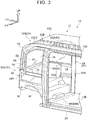
FIG. 3 is a perspective view of the vehicle ofFIG. 1 that is obliquely viewed from a rear side of the vehicle; and -
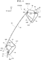
FIG. 4 is an enlarged plane sectional view of a pillar, illustrating an enlarged portion cut along a line IV-IV inFIG. 1 . - A
vehicle 10 to which a vehicle pillar structure according to an embodiment is applied is described below with reference toFIG. 1 to FIG. 4 . An arrow FR shown as appropriate in the drawings indicates a front side of the vehicle. An arrow UP shown as appropriate in the drawings indicates a top side of the vehicle. An arrow LH shown as appropriate in the drawings indicates a left side of the vehicle. Unless otherwise specified, terms "front", "rear", "up", "down", "right", and "left" as used in the following description mean the front and rear in a front-and-rear direction of the vehicle, the top and bottom in a vertical direction of the vehicle, and the right and left in a case where the vehicle is oriented in a traveling direction. - As partially illustrated in
FIG. 1 , thevehicle 10 includes a frame structure (not illustrated) and abody 12. The frame structure is arranged at a lower part of thevehicle 10 to serve as a framework member at the lower part of the vehicle. Thebody 12 is fixed onto the frame structure. - The
body 12 is formed into a substantially rectangular parallelepiped shape that is long in the front-and-rear direction of the vehicle. Thebody 12 includes a pair of right and leftside walls 12A, afloor 12B, and aroof 12C. Thefloor 12B is interposed between theside walls 12A in a width direction of the vehicle to serve as a floor surface of avehicle cabin 14. Theroof 12C serves as a ceiling of thevehicle cabin 14. In this embodiment, a vehicle seat (not illustrated) is provided as a driver's seat in thevehicle cabin 14 on a front side of the vehicle and at a center in the width direction of the vehicle. - As illustrated in
FIG. 1 andFIG. 2 , a front windshield glass 22 (hereinafter referred to as "Fr glass 22") is provided at a front part of thevehicle cabin 14 to cover anopening 20 defined at the front of thevehicle 10. TheFr glass 22 is a transparent window member fixed to theopening 20, and separates the inside and outside of thevehicle cabin 14. The thickness direction of theFr glass 22 is the front-and-rear direction of the vehicle (substantial front-and-rear direction of the vehicle). TheFr glass 22 extends in the width direction and the vertical direction of the vehicle, and is slightly inclined toward the rear of the vehicle with decreasing distance to the top of the vehicle in side view. TheFr glass 22 corresponds to an example of a "windshield glass" of the present invention. - The upper end of the
Fr glass 22 is connected to a roof header 12C1 extending in the width direction of the vehicle to define an upper edge of theopening 20. The roof header 12C1 constitutes a part of a framework of theroof 12C, and is arranged at the front end of theroof 12C. For example, theroof header 12C 1 is a reinforcement member whose vertical sectional shape is a closed sectional shape, and extends along the width direction of the vehicle. The lower end of theFr glass 22 is connected to a cowl (reference symbol is omitted) extending in the width direction of the vehicle to define a lower edge of theopening 20. - The
Fr glass 22 has a constant thickness, and has a gently curved shape so that a middle part of theFr glass 22 in the width direction of the vehicle projects to the front side of the vehicle. A pair of right and leftpillars 30 serving as vehicle pillars is provided on an outer side of theFr glass 22 in the width direction of the vehicle. - Each of the right and left
pillars 30 has a curved shape having a curved part above the middle in its extending direction and projecting to the front side and the top side of the vehicle in side view. The lower part of thepillar 30 is astraight portion 30A. Thestraight portion 30A extends in the vertical direction of the vehicle (substantial vertical direction of the vehicle) along an outer end of theFr glass 22 in the width direction of the vehicle. The upper part of thepillar 30 is acurved portion 30B. Thecurved portion 30B is gently curved from the upper end of thestraight portion 30A, and extends substantially toward the rear of the vehicle (in the front-and-rear direction of the vehicle). Although theleft pillar 30 in the width direction of the vehicle is described below, theright pillar 30 in the width direction of the vehicle has a similar structure. - The
pillar 30 includes afirst pillar 32 that constitutes a front part of thepillar 30, and asecond pillar 40 that constitutes a rear part of thepillar 30. Thepillar 30 further includes afirst reinforcement member 52 and asecond reinforcement member 54 that couple thefirst pillar 32 and thesecond pillar 40 together in the front-and-rear direction of the vehicle. - As illustrated in
FIG. 1 , thefirst pillar 32 has a curved shape having a curved part above the middle in its extending direction and projecting to the front side and the top side of the vehicle in side view. Thefirst pillar 32 has alower pillar portion 32A that constitutes thestraight portion 30A of thepillar 30. Thelower pillar portion 32A is constituted by a firstouter pillar portion 34 and a firstinner pillar portion 36 described later. Thefirst pillar 32 also has anupper pillar portion 32B that constitutes thecurved portion 30B of thepillar 30. Theupper pillar portion 32B is constituted by the front end of a roof side rail 12C2 of theroof 12C. That is, thepillar 30 is integrated with the roof side rail 12C2 of thevehicle 10 such that the front end of the roof side rail 12C2 serves as a part of thefirst pillar 32. -
FIG. 4 is a plane sectional view illustrating a state in which thestraight portion 30A of thepillar 30 is cut along a line IV-IV inFIG. 1 in a direction orthogonal to the extending direction (vertical direction of the vehicle). - As illustrated in
FIG. 4 , the sectional shape of thelower pillar portion 32A of thefirst pillar 32 is a closed sectional shape defined by the firstouter pillar portion 34 and the firstinner pillar portion 36. The firstouter pillar portion 34 is made of a steel sheet, and has a substantially hat-shaped cross section open to thevehicle cabin 14. Referring toFIG. 4 , the firstouter pillar portion 34 includes an outer side wall 34A and a pair ofside walls 34B. The outer side wall 34A faces outside in the width direction of the vehicle. Theside walls 34B extend inward in the width direction of the vehicle from the front end and the rear end of the outer side wall 34A, and face each other in the front-and-rear direction of the vehicle. Afront flange 34C is formed at the distal end of theside wall 34B on the front side of the vehicle. Arear flange 34D is formed at the distal end of theside wall 34B on the rear side of the vehicle. - The first
inner pillar portion 36 is made of a steel sheet, and the sectional shape is substantially a crank shape. The firstinner pillar portion 36 closes the opening of the firstouter pillar portion 34 from thevehicle cabin 14 side. The front end and the rear end of the firstinner pillar portion 36 are joined to thefront flange 34C and therear flange 34D of the firstouter pillar portion 34, respectively. Thus, thelower pillar portion 32A of thefirst pillar 32 has a closed section structure defined by the firstouter pillar portion 34 and the firstinner pillar portion 36. - A first
outer panel 38 is arranged on a front side of the firstouter pillar portion 34 in the front-and-rear direction of the vehicle to serve as an outer design surface of thelower pillar portion 32A. The firstouter panel 38 substantially has a U-shape open to the rear of the vehicle, and covers theside wall 34B of the firstouter pillar portion 34 on the front side of the vehicle from the outside of thevehicle cabin 14.First attachment flanges 38A are formed at the open end of the firstouter panel 38 to extend away from each other. Thefirst attachment flanges 38A are joined to the outer side wall 34A and thefront flange 34C of the firstouter pillar portion 34 from the outside of thevehicle cabin 14. Thus, a closed section structure is defined by the firstouter pillar portion 34 and the firstouter panel 38. - The outer end of the
Fr glass 22 in the width direction of the vehicle is joined, via a water-stop sealer 50, to thefirst attachment flange 38A joined to thefront flange 34C. The front end of atransparent window member 60 described later in the front-and-rear direction of the vehicle is joined, via a water-stop sealer 50, to thefirst attachment flange 38A joined to the outer side wall 34A. - As illustrated in
FIG. 1 andFIG. 3 , the lower end of thelower pillar portion 32A is coupled to abumper reinforcement 16 via a gusset (reference symbol is omitted). Thebumper reinforcement 16 is a part of the frame structure serving as the framework member at the lower part of the vehicle, and extends in an elongated shape so that the width direction of the vehicle is a longitudinal direction. Both longitudinal ends of thebumper reinforcement 16 are fixed to the front ends (outer ends in the front-and-rear direction of the vehicle) of a pair of right and leftside members 18 arranged away from each other in the width direction of the vehicle. Eachside member 18 is a part of the frame structure serving as the framework member at the lower part of the vehicle, and theside member 18 extends in the front-and-rear direction of the vehicle that is a longitudinal direction. Thebumper reinforcement 16 supports a front bumper (not illustrated) of thevehicle 10 from the rear side of the vehicle. - The upper end of the
lower pillar portion 32A is coupled to the front end of the roof side rail 12C2 (outer end in the front-and-rear direction of the vehicle) that constitutes theupper pillar portion 32B. The roof side rail 12C2 constitutes the framework of theroof 12C, and is arranged at the outer end of theroof 12C in the width direction of the vehicle to extend in the front-and-rear direction of the vehicle. Similarly to thelower pillar portion 32A, the vertical sectional shape of the roof side rail 12C2 is a closed sectional shape, and the roof side rail 12C2 includes an outer roof side portion and an inner roof side portion (reference symbols are omitted). The outer roof side portion is arranged on an outer side in the width direction of the vehicle. The inner roof side portion is arranged on an inner side in the width direction of the vehicle with respect to the outer roof side portion. The sectional area of the closed section of the front end of the roof side rail 12C2 (upper pillar portion 32B) is set larger than the sectional area of the closed section of thelower pillar portion 32A. Therefore, in thefirst pillar 32, theupper pillar portion 32B near the ceiling of thevehicle cabin 14 is thicker than thelower pillar portion 32A near the height of a line of sight of an occupant in thevehicle cabin 14. Further, the sectional rigidity of theupper pillar portion 32B is set higher than the sectional rigidity of thelower pillar portion 32A. - The
lower pillar portion 32A and the roof side rail 12C2 are coupled together by joining their joint flanges (not illustrated). One end of the roof header 12C1 in its extending direction is coupled to the part where thelower pillar portion 32A and theupper pillar portion 32B are coupled together. Thus, a framework structure having an annular shape when viewed in the front-and-rear direction of the vehicle is formed at the front (and rear) of thevehicle 10 by the roof header 12C1, thebumper reinforcement 16, and the pair of right and leftfirst pillars 32. - Similarly to the
first pillar 32, thesecond pillar 40 that constitutes the rear part of thepillar 30 in the front-and-rear direction of the vehicle has a curved shape projecting to the front side and the top side of the vehicle in side view. Thesecond pillar 40 includes a secondouter pillar portion 42 and a secondinner pillar portion 44. The secondouter pillar portion 42 is arranged on an outer side in the width direction of the vehicle. The secondinner pillar portion 44 is arranged on an inner side in the width direction of the vehicle with respect to the secondouter pillar portion 42. - As illustrated in
FIG. 1 , thesecond pillar 40 is arranged away from thefirst pillar 32 by a predetermined distance in the front-and-rear direction of the vehicle. More specifically, the upper end of thesecond pillar 40 is arranged near the upper end of thefirst pillar 32. The distance between thesecond pillar 40 and thefirst pillar 32 gradually increases in the front-and-rear direction of the vehicle (substantial front-and-rear direction of the vehicle) with decreasing distance from the upper end to the lower end. The lower part of thesecond pillar 40 is offset outward in the width direction of the vehicle with respect to the middle part of the first pillar 32 (seeFIG. 3 ). - As illustrated in
FIG. 4 , the sectional shape of thesecond pillar 40 is a closed sectional shape defined by the secondouter pillar portion 42 and the secondinner pillar portion 44. The secondouter pillar portion 42 is made of a steel sheet, and has a substantially hat-shaped cross section open to thevehicle cabin 14. Referring to the plane section illustrated inFIG. 4 , the secondouter pillar portion 42 includes anouter side wall 42A and a pair ofside walls 42B. Theouter side wall 42A faces outside in the width direction of the vehicle. Theside walls 42B extend inward in the width direction of the vehicle from the front end and the rear end of theouter side wall 42A, and face each other in the front-and-rear direction of the vehicle. Afront flange 42C is formed at the distal end of theside wall 42B on the front side of the vehicle. Arear flange 42D is formed at the distal end of theside wall 42B on the rear side of the vehicle. - The second
inner pillar portion 44 is made of a steel sheet, and the sectional shape is substantially a crank shape. The secondinner pillar portion 44 closes the opening of the secondouter pillar portion 42 from thevehicle cabin 14 side. The front end and the rear end of the secondinner pillar portion 44 are joined to thefront flange 42C and therear flange 42D of the secondouter pillar portion 42, respectively. Thus, thesecond pillar 40 has a closed section structure defined by the secondouter pillar portion 42 and the secondinner pillar portion 44. Similarly to thefirst pillar 32, the sectional area of the closed section of the part that constitutes thecurved portion 30B of thepillar 30 is set larger than the sectional area of the closed section of the part that constitutes thestraight portion 30A of thepillar 30. - A second
outer panel 46 is arranged on a rear side of the secondouter pillar portion 42 in the front-and-rear direction of the vehicle to serve as an outer design surface of thesecond pillar 40. The secondouter panel 46 substantially has a U-shape open to the front of the vehicle, and covers theside wall 42B of the secondouter pillar portion 42 on the rear side of the vehicle from the outside of thevehicle cabin 14.Second attachment flanges 46A are formed at the open end of the secondouter panel 46 to extend away from each other. Thesecond attachment flanges 46A are joined to theouter side wall 42A and therear flange 42D of the secondouter pillar portion 42 from the outside of thevehicle cabin 14. Thus, thesecond pillar 40 has a closed section structure defined by the secondouter pillar portion 42 and the secondouter panel 46. - The rear end of the
transparent window member 60 described later in the front-and-rear direction of the vehicle is joined, via a water-stop sealer 50, to thesecond attachment flange 46A joined to therear flange 42D. The front end of aside glass 24 in the front-and-rear direction of the vehicle is joined, via a water-stop sealer 50, to thesecond attachment flange 46A joined to theouter side wall 42A. - As illustrated in
FIG. 1 to FIG. 3 , thefirst pillar 32 and thesecond pillar 40 are coupled together in the front-and-rear direction of the vehicle by using thefirst reinforcement member 52 and thesecond reinforcement member 54. Each of thefirst reinforcement member 52 and thesecond reinforcement member 54 is made of a steel sheet, and is formed into an elongated shape so that the front-and-rear direction of the vehicle is a longitudinal direction. For example, each of thefirst reinforcement member 52 and thesecond reinforcement member 54 includes an inner panel and an outer panel (not illustrated) each substantially having a hat shape in vertical sectional view. The inner panel and the outer panel are joined together in the width direction of the vehicle to obtain a reinforcement member having a closed section structure. - The
first reinforcement member 52 couples thefirst pillar 32 and thesecond pillar 40 together in the front-and-rear direction of the vehicle at a part corresponding to a boundary between thestraight portion 30A and thecurved portion 30B of thepillar 30. A stress caused by a load input in the event of front-end collision (or rear-end collision) of the vehicle concentrates on the part corresponding to the boundary between thestraight portion 30A and thecurved portion 30B of thepillar 30. By arranging thefirst reinforcement member 52 at the boundary between thestraight portion 30A and thecurved portion 30B, the part where the stress concentrates in the event of front-end collision (or rear-end collision) of the vehicle can be reinforced effectively. - In the
first pillar 32, the part where thelower pillar portion 32A and theupper pillar portion 32B (roof side rail 12C2) are coupled together is located at the boundary between thestraight portion 30A and thecurved portion 30B of thepillar 30, and the strength structurally decreases at this part. Thefirst reinforcement member 52 also has a function of reinforcing the part where thelower pillar portion 32A and theupper pillar portion 32B are coupled together, thereby effectively increasing the strength of thefirst pillar 32. In thefirst pillar 32, the part coupled to thefirst reinforcement member 52 and the part coupled to the roof header 12C1 are located at substantially the same height position. Thus, thefirst reinforcement member 52 is coupled to the roof header 12C1 via thefirst pillar 32. - The
second reinforcement member 54 is arranged below thefirst reinforcement member 52 in the vertical direction of the vehicle, and couples the middle part of thefirst pillar 32 and the lower part of thesecond pillar 40 together in the front-and-rear direction of the vehicle. Thesecond reinforcement member 54 has a function of increasing the rigidity and strength of thepillar 30 such that the load input to thefirst pillar 32 in the event of front-end collision (or rear-end collision) of the vehicle is transmitted to thesecond pillar 40. - As illustrated in
FIG. 1 , thepillar 30 having the structure described above has a substantiallyrectangular opening 56 defined by the lower parts of thefirst pillar 32 and thesecond pillar 40, thefirst reinforcement member 52, and thesecond reinforcement member 54. Theopening 56 is covered with thetransparent window member 60 interposed between thefirst pillar 32 and thesecond pillar 40. Thetransparent window member 60 is made of glass or a transparent resin, and constitutes a side part of thevehicle cabin 14 in the width direction of the vehicle. Thus, the occupant in thevehicle cabin 14 can view the outside of thevehicle 10 through thetransparent window member 60 at theopening 56 of thepillar 30. - As illustrated in
FIG. 3 , the upper end and the lower end of thepillar 30 having the structure described above are supported from the rear side of the vehicle by aframework member 62 that constitutes a framework of thebody 12 of thevehicle 10. Theframework member 62 includes a pair of right and leftvertical pillar portions 64 and areinforcement portion 66 that couples the upper ends of thevertical pillar portions 64 together in the width direction of the vehicle and couples the lower ends of thevertical pillar portions 64 together in the width direction of the vehicle. Theframework member 62 has an annular shape when viewed in the front-and-rear direction of the vehicle. - The
vertical pillar portions 64 are arranged away from each other in the width direction of the vehicle, and extend in an elongated shape along the vertical direction of the vehicle. Thevertical pillar portions 64 constitute side parts of theframework member 62 in the width direction of the vehicle. Eachvertical pillar portion 64 has a hollow shape defined by aninner panel 64A and anouter panel 64B. Theinner panel 64A is arranged on an inner side in the width direction of the vehicle. Theouter panel 64B is joined to theinner panel 64A from an outer side in the width direction of the vehicle. - The lower end of the
vertical pillar portion 64 is joined to arocker 26 and one end of afloor reinforcement 66B described later. Therocker 26 is arranged at a lower part of theside wall 12A of thevehicle 10. The upper end of thevertical pillar portion 64 is joined to the roof side rail 12C2 and one end of aroof reinforcement 66A described later. - The
reinforcement portion 66 that couples thevertical pillar portions 64 together includes theroof reinforcement 66A that couples the upper ends of thevertical pillar portions 64 together, and thefloor reinforcement 66B that couples the lower ends of thevertical pillar portions 64 together. Theroof reinforcement 66A is a hollow columnar member that constitutes the framework of theroof 12C and extends in the width direction of the vehicle. Both ends of theroof reinforcement 66A in its extending direction are coupled to the upper ends of thevertical pillar portions 64 via coupling portions (not illustrated). - The
floor reinforcement 66B is arranged below thefloor 12B of thevehicle cabin 14 to serve as a reinforcement member for thefloor 12B. Thefloor reinforcement 66B is a hollow columnar member extending in the width direction of the vehicle. Joint flanges (not illustrated) formed at both ends of thefloor reinforcement 66B in its extending direction are joined to theinner panels 64A of thevertical pillar portions 64. Thus, thefloor reinforcement 66B couples the lower ends of thevertical pillar portions 64 together in the width direction of the vehicle. - As illustrated in
FIG. 1 , the upper end of thefirst pillar 32 and the upper end of thesecond pillar 40 that constitute the upper end of thepillar 30 are joined to the upper end of thevertical pillar portion 64. The upper end of thefirst pillar 32 is a part where the roof side rail 12C2 and thevertical pillar portion 64 are joined together. - A middle part of the
vertical pillar portion 64 is coupled to the lower part of thesecond pillar 40 via athird reinforcement member 70. Similarly to thefirst reinforcement member 52 and thesecond reinforcement member 54, thethird reinforcement member 70 is made of a steel sheet, and is formed into an elongated shape so that the front-and-rear direction of the vehicle is a longitudinal direction. For example, thethird reinforcement member 70 includes an inner panel and an outer panel (not illustrated) each substantially having a hat shape in vertical sectional view. The inner panel and the outer panel are joined together in the width direction of the vehicle to obtain a reinforcement member having a closed section structure. - The
third reinforcement member 70 is arranged at the same height position as that of thesecond reinforcement member 54. One end of thethird reinforcement member 70 is coupled to the second reinforcement member via thesecond pillar 40. The other end of thethird reinforcement member 70 is coupled to the middle part of thevertical pillar portion 64. Therefore, the load input to thefirst pillar 32 in the event of front-end collision (or rear-end collision) of thevehicle 10 is transmitted to thevertical pillar portion 64 via thesecond reinforcement member 54 and thethird reinforcement member 70. - The vehicle pillar structure according to this embodiment includes the
pillar 30 including thefirst pillar 32 extending along the outer end of theFr glass 22 in the width direction of the vehicle, and thesecond pillar 40 arranged away from thefirst pillar 32 by the predetermined distance in the front-and-rear direction of the vehicle (substantial front-and-rear direction of the vehicle). In thepillar 30, thetransparent window member 60 is interposed between thefirst pillar 32 and thesecond pillar 40. Thetransparent window member 60 covers theopening 56 defined by thefirst pillar 32 and thesecond pillar 40. For example, at the front part or the rear part of thevehicle 10, the occupant in thevehicle cabin 14 can view the outside of thevehicle 10 through thetransparent window member 60 at theopening 56 of thepillar 30. Therefore, a blind spot of thepillar 30 is reduced for the occupant in thevehicle cabin 14. Thus, the visibility can be improved. - The
pillar 30 has the curved shape defined by thestraight portion 30A extending in the vertical direction of the vehicle (substantial vertical direction of the vehicle) in side view, and thecurved portion 30B curved from the upper end of thestraight portion 30A and extending in the front-and-rear direction of the vehicle. Since the upper part of thepillar 30 extends in the front-and-rear direction of the vehicle by thecurved portion 30B, the vehicle cabin space can be increased as compared to a vehicle pillar inclined in a straight shape in side view. - In this embodiment, the
pillar 30 is integrated with the roof side rail 12C2. Therefore, the load input to thepillar 30 in the event of, for example, front-end or rear-end collision of thevehicle 10 can efficiently be transmitted to the roof side rail 12C2 and theroof 12C. - Since the
pillar 30 is curved at the boundary between thestraight portion 30A and thecurved portion 30B, the stress caused by the load input in the event of front-end or rear-end collision of thevehicle 10 concentrates on this boundary. - In the
pillar 30 of this embodiment, thefirst reinforcement member 52 that couples thefirst pillar 32 and thesecond pillar 40 together is provided at the boundary between thestraight portion 30A and thecurved portion 30B. Therefore, thepillar 30 is structured such that thefirst reinforcement member 52 effectively reinforces the part where the stress concentrates in the event of front-end or rear-end collision of thevehicle 10. Thus, deformation of thepillar 30 can be suppressed in the event of front-end or rear-end collision of thevehicle 10. - In this embodiment, the
pillar 30 can effectively be reinforced by coupling the roof header 12C1 to the part of thepillar 30 where the stress concentrates in the event of front-end or rear-end collision of thevehicle 10. Thus, the deformation of thepillar 30 is suppressed in the event of front-end or rear-end collision of the vehicle. - In this embodiment, the load input to the lower part of the
pillar 30 in the event of front-end or rear-end collision of thevehicle 10 is distributed to thefirst pillar 32 and thesecond pillar 40 via thesecond reinforcement member 54. The lower part of thesecond pillar 40 is offset outward in the width direction of the vehicle with respect to the middle part of thefirst pillar 32. Therefore, the load input to thepillar 30 in the event of front-end or rear-end collision of thevehicle 10 can be distributed outward in the width direction of the vehicle. Thus, deformation at the front or rear of the vehicle can be suppressed in the event of front-end or rear-end collision of thevehicle 10. - In this embodiment, the
framework member 62 is arranged on the rear side of thepillar 30 in the front-and-rear direction of the vehicle (inner side in the front-and-rear direction of the vehicle). The side part of theframework member 62 in the width direction of the vehicle is constituted by thevertical pillar portion 64 extending in the vertical direction of the vehicle. In thepillar 30, the upper ends of thefirst pillar 32 and thesecond pillar 40 are coupled to thevertical pillar portion 64. Therefore, the load input to thepillar 30 in the event of front-end or rear-end collision of the vehicle is transmitted to theframework member 62 arranged on the rear side. Thus, the rigidity and strength of thepillar 30 of thevehicle 10 can be increased. - In this embodiment, the load input to the lower part of the
second pillar 40 of thepillar 30 in the event of front-end or rear-end collision of thevehicle 10 is transmitted to thevertical pillar portion 64 of theframework member 62 via thethird reinforcement member 70. Thus, deformation of thesecond pillar 40 and deformation at the front or rear of thevehicle 10 are suppressed in the event of front-end or rear-end collision of thevehicle 10. - In this embodiment, the
framework member 62 includes thevertical pillar portions 64 and thereinforcement portion 66 that couples the upper ends and the lower ends of thevertical pillar portions 64 together in the width direction of the vehicle. Therefore, theframework member 62 has the annular shape when viewed in the front-and-rear direction of the vehicle, and the rigidity and strength are increased. Thus, the rigidity and strength of thepillar 30 of thevehicle 10 can further be increased, and the deformation of thepillar 30 can be suppressed in the event of front-end or rear-end collision of thevehicle 10. - In this embodiment, the sectional area of the
curved portion 30B of thepillar 30 is set larger than the sectional area of thestraight portion 30A of thepillar 30. More specifically, the sectional areas of the upper parts of thefirst pillar 32 and thesecond pillar 40 are set larger than the sectional areas of the lower parts of thefirst pillar 32 and thesecond pillar 40. Thus, the visibility can be secured by reducing the thicknesses of the lower parts of thefirst pillar 32 and thesecond pillar 40 near the height position of the line of sight of the occupant in thevehicle cabin 14. Further, the requirement for the rigidity of thepillar 30 can be satisfied by increasing the thicknesses of the upper parts of thefirst pillar 32 and thesecond pillar 40 near the ceiling of thevehicle cabin 14. - For example, when the sectional areas of the upper parts of the
first pillar 32 and thesecond pillar 40 are secured sufficiently, deformation of the front part or the rear part of thevehicle 10 can effectively be suppressed in the event of overturn of thevehicle 10 due to collision with an obstacle. That is, when thevehicle 10 is overturned, a load is input to the upper part of thepillar 30 and theroof 12C from one side in the width direction of the vehicle. When the sectional areas of the upper parts of thefirst pillar 32 and thesecond pillar 40 are secured sufficiently, the sectional rigidity of the upper part of thepillar 30 is increased. Thus, the deformation of the front part or the rear part of the vehicle can be suppressed in the event of overturn of the vehicle. - In this embodiment, the
first reinforcement member 52 and the roof header 12C1 are coupled together via thefirst pillar 32 of thepillar 30. Therefore, in the event of overturn of the vehicle, a load input to theroof 12C located on the side of thevehicle 10 where collision occurs can be distributed, via thefirst reinforcement member 52 and the roof header 12C1, to thepillar 30 located on the side where collision does not occur. - In the embodiment described above, the
pillar 30 is integrated with the roof side rail 12C2 by forming theupper pillar portion 32B of thefirst pillar 32 from the front end of the roof side rail 12C2. The present invention is not limited to this case. Thepillar 30 may be integrated with the roof side rail 12C2 by forming theupper pillar portion 32B of thefirst pillar 32 from the firstouter pillar portion 34 and the firstinner pillar portion 36 that constitute thelower pillar portion 32A, and coupling the upper end of thefirst pillar 32 to the front end of the roof side rail 12C2. - In the embodiment described above, the
framework member 62 is formed into the annular shape by thevertical pillar portions 64 and thereinforcement portion 66 when viewed in the front-and-rear direction of the vehicle. The present invention is not limited to this case. Theframework member 62 may include only the right and leftvertical pillar portions 64. - In the embodiment described above, the vehicle pillar structure is applied to the front part of the
vehicle 10. A similar vehicle pillar structure may be applied to the rear part of thevehicle 10.
Claims (9)
- A vehicle pillar structure comprising:a vehicle pillar (30) including
a first pillar (32) extending along an outer end of a windshield glass (22) in a width direction of a vehicle (10), and
a second pillar (40) disposed away from the first pillar (32) by a predetermined distance in a front-and-rear direction of the vehicle (10); anda transparent window member (60) through which an outside of the vehicle (10) is viewable, the transparent window member (60) being interposed between the first pillar (32) and the second pillar (40) and covering an opening defined by the first pillar (32) and the second pillar (40),wherein the vehicle pillar (30) has a curved shape defined by a straight portion (30A) extending in a vertical direction of the vehicle (10) in side view, and a curved portion (30B) curved from an upper end of the straight portion (30A) and extending in the front-and-rear direction of the vehicle (10). - The vehicle pillar structure according to claim 1, wherein the curved portion (30B) is integrated with a roof side rail (12C2), the roof side rail (12C2) constituting a framework of a roof (12C) serving as a ceiling of a vehicle cabin (14) of the vehicle (10) and disposed at an outer end of the roof (12C) in the width direction of the vehicle (10) to extend in the front-and-rear direction of the vehicle (10).
- The vehicle pillar structure according to claim 1 or 2, wherein a first reinforcement member (52) that couples the first pillar (32) and the second pillar (40) together is provided at a boundary between the straight portion (30A) and the curved portion (30B).
- The vehicle pillar structure according to any of claims 1 to 3, wherein one end of a roof header (12C1) is coupled to a boundary between the straight portion (30A) and the curved portion (30B), the roof header (12C1) constituting a framework of a roof (12C) serving as a ceiling of a vehicle cabin (14) of the vehicle (10), and disposed at an outer end of the roof (12C) in the front-and-rear direction of the vehicle (10) to extend in the width direction of the vehicle (10).
- The vehicle pillar structure according to any of claims 1 to 4, wherein:a middle part of the first pillar (32) and a lower part of the second pillar (40) are coupled together by a second reinforcement member (54); andthe lower part of the second pillar (40) is disposed so as to be offset outward in the width direction of the vehicle (10) with respect to the middle part of the first pillar (32).
- The vehicle pillar structure according to any of claims 1 to 5, wherein:a framework member (62) is disposed on an inner side of the vehicle pillar (30) in the front-and-rear direction of the vehicle (10), the framework member (62) including a vertical pillar portion (64) extending in the vertical direction of the vehicle (10);the vertical pillar portion (64) constitutes a side part of the framework member (62) in the width direction of the vehicle (10); andan upper end of the first pillar (32) and an upper end of the second pillar (40) are coupled to the vertical pillar portion (64).
- The vehicle pillar structure according to claim 6, wherein a lower part of the second pillar (40) is coupled to the vertical pillar portion (64) of the framework member (62) via a third reinforcement member (70).
- The vehicle pillar structure according to claim 6 or 7, wherein the framework member (62) has an annular shape when viewed in the front-and-rear direction of the vehicle (10), the annular shape being defined by a pair of the vertical pillar portions (64) and a reinforcement portion (66) that couples upper ends of the pair of the vertical pillar portions (64) together in the width direction of the vehicle (10) and couples lower ends of the pair of the vertical pillar portions (64) together in the width direction of the vehicle (10).
- The vehicle pillar structure according to any of claims 1 to 8, wherein a sectional area of the curved portion (30B) is larger than a sectional area of the straight portion (30A).
Applications Claiming Priority (1)
| Application Number | Priority Date | Filing Date | Title |
|---|---|---|---|
| JP2020020947A JP7338498B2 (en) | 2020-02-10 | 2020-02-10 | Vehicle pillar structure |
Publications (3)
| Publication Number | Publication Date |
|---|---|
| EP3862251A1 true EP3862251A1 (en) | 2021-08-11 |
| EP3862251B1 EP3862251B1 (en) | 2025-10-01 |
| EP3862251C0 EP3862251C0 (en) | 2025-10-01 |
Family
ID=74187215
Family Applications (1)
| Application Number | Title | Priority Date | Filing Date |
|---|---|---|---|
| EP21152188.5A Active EP3862251B1 (en) | 2020-02-10 | 2021-01-18 | Vehicle pillar structure |
Country Status (4)
| Country | Link |
|---|---|
| US (1) | US11433948B2 (en) |
| EP (1) | EP3862251B1 (en) |
| JP (1) | JP7338498B2 (en) |
| CN (1) | CN113247103A (en) |
Citations (5)
| Publication number | Priority date | Publication date | Assignee | Title |
|---|---|---|---|---|
| JP2006273057A (en) * | 2005-03-28 | 2006-10-12 | Toyota Motor Corp | Pillar structure |
| US20090267330A1 (en) * | 2008-04-29 | 2009-10-29 | Gm Global Technology Operations, Inc. | Motor vehicle with an a-column and airbag incorporated therein |
| JP2018162021A (en) | 2017-03-27 | 2018-10-18 | トヨタ自動車株式会社 | Vehicle pillar structure |
| US20190144042A1 (en) * | 2017-11-14 | 2019-05-16 | Toyota Jidosha Kabushiki Kaisha | Pillar structure for a vehicle |
| EP3511230A1 (en) * | 2018-01-16 | 2019-07-17 | Toyota Jidosha Kabushiki Kaisha | Vehicle pillar structure and vehicle side portion structure |
Family Cites Families (11)
| Publication number | Priority date | Publication date | Assignee | Title |
|---|---|---|---|---|
| GB2371525B (en) * | 2001-01-30 | 2004-07-14 | Edgar Padbury Coleman | Improvements in motor vehicles |
| DE102005049945A1 (en) | 2005-10-19 | 2007-04-26 | GM Global Technology Operations, Inc., Detroit | Windshield assembly |
| KR100680829B1 (en) * | 2005-11-30 | 2007-02-08 | 현대자동차주식회사 | Front pillar structure for bus |
| DE102007014116A1 (en) * | 2007-03-23 | 2008-09-25 | Ford Global Technologies, LLC, Dearborn | Column, particularly A-column for use as part of body structure of motor vehicle, has hollow profile with closed cross section, where hollow profile is connected to body structure with intended connection plate |
| GB2479363A (en) | 2010-04-07 | 2011-10-12 | Gm Global Tech Operations Inc | Partially transparent vehicle body component |
| CN101961984B (en) * | 2010-08-31 | 2012-06-06 | 珠海市银通新动力科技有限公司 | Electric motor coach |
| JP5673076B2 (en) * | 2010-12-21 | 2015-02-18 | スズキ株式会社 | Structure around the front pillar base of automobiles |
| JP5400862B2 (en) | 2011-11-25 | 2014-01-29 | 本田技研工業株式会社 | Body side structure |
| JP5940814B2 (en) | 2012-01-17 | 2016-06-29 | 本田技研工業株式会社 | Body structure |
| CN203601387U (en) * | 2013-11-07 | 2014-05-21 | 奇瑞万达贵州客车股份有限公司 | Pillar A structure of automobile |
| JP6897222B2 (en) | 2017-03-27 | 2021-06-30 | トヨタ自動車株式会社 | Front pillar structure |
-
2020
- 2020-02-10 JP JP2020020947A patent/JP7338498B2/en active Active
-
2021
- 2021-01-14 CN CN202110047591.8A patent/CN113247103A/en active Pending
- 2021-01-18 EP EP21152188.5A patent/EP3862251B1/en active Active
- 2021-01-25 US US17/156,633 patent/US11433948B2/en active Active
Patent Citations (5)
| Publication number | Priority date | Publication date | Assignee | Title |
|---|---|---|---|---|
| JP2006273057A (en) * | 2005-03-28 | 2006-10-12 | Toyota Motor Corp | Pillar structure |
| US20090267330A1 (en) * | 2008-04-29 | 2009-10-29 | Gm Global Technology Operations, Inc. | Motor vehicle with an a-column and airbag incorporated therein |
| JP2018162021A (en) | 2017-03-27 | 2018-10-18 | トヨタ自動車株式会社 | Vehicle pillar structure |
| US20190144042A1 (en) * | 2017-11-14 | 2019-05-16 | Toyota Jidosha Kabushiki Kaisha | Pillar structure for a vehicle |
| EP3511230A1 (en) * | 2018-01-16 | 2019-07-17 | Toyota Jidosha Kabushiki Kaisha | Vehicle pillar structure and vehicle side portion structure |
Also Published As
| Publication number | Publication date |
|---|---|
| US20210245814A1 (en) | 2021-08-12 |
| JP7338498B2 (en) | 2023-09-05 |
| US11433948B2 (en) | 2022-09-06 |
| EP3862251B1 (en) | 2025-10-01 |
| CN113247103A (en) | 2021-08-13 |
| JP2021126916A (en) | 2021-09-02 |
| EP3862251C0 (en) | 2025-10-01 |
Similar Documents
| Publication | Publication Date | Title |
|---|---|---|
| US9592856B2 (en) | Upper vehicle-body structure of vehicle | |
| CN107848577B (en) | car body rear structure | |
| EP2740651B1 (en) | Vehicle body lateral structure | |
| US7264302B2 (en) | Lower body construction | |
| JP6658645B2 (en) | Pillar structure for vehicles | |
| US11008046B2 (en) | Vehicle body structure | |
| JP6965766B2 (en) | Vehicle front pillar structure and vehicle side structure | |
| JP2001334955A (en) | Vehicle door reinforcement structure | |
| US20210086837A1 (en) | Vehicle body structure of vehicle | |
| JP5353364B2 (en) | Lower body structure of the vehicle | |
| JP2019123368A (en) | Vehicle pillar structure and vehicle side part structure | |
| JP7300083B2 (en) | Vehicle side body structure | |
| JP7220800B2 (en) | car body structure | |
| JP2002347655A (en) | Pillar reinforcing structure for automobile | |
| JP5857412B2 (en) | Reinforcement structure at the front of the vehicle | |
| JPH11235983A (en) | Front pillar structure of automobile | |
| JPH06144299A (en) | Lower car body structure | |
| EP3862251B1 (en) | Vehicle pillar structure | |
| JP2009040127A (en) | Front body structure of automobile | |
| EP4431371A1 (en) | Vehicle body side structure of vehicle and vehicle body structure of vehicle | |
| JPH11291947A (en) | Car body structure | |
| CN111703506A (en) | vehicle substructure | |
| JP2000142466A (en) | Structure of the roof side of the car | |
| JP7358922B2 (en) | Vehicle front structure | |
| JP2004082861A (en) | Side body structure of vehicle |
Legal Events
| Date | Code | Title | Description |
|---|---|---|---|
| PUAI | Public reference made under article 153(3) epc to a published international application that has entered the european phase |
Free format text: ORIGINAL CODE: 0009012 |
|
| STAA | Information on the status of an ep patent application or granted ep patent |
Free format text: STATUS: REQUEST FOR EXAMINATION WAS MADE |
|
| 17P | Request for examination filed |
Effective date: 20210118 |
|
| AK | Designated contracting states |
Kind code of ref document: A1 Designated state(s): AL AT BE BG CH CY CZ DE DK EE ES FI FR GB GR HR HU IE IS IT LI LT LU LV MC MK MT NL NO PL PT RO RS SE SI SK SM TR |
|
| STAA | Information on the status of an ep patent application or granted ep patent |
Free format text: STATUS: EXAMINATION IS IN PROGRESS |
|
| 17Q | First examination report despatched |
Effective date: 20230313 |
|
| GRAP | Despatch of communication of intention to grant a patent |
Free format text: ORIGINAL CODE: EPIDOSNIGR1 |
|
| STAA | Information on the status of an ep patent application or granted ep patent |
Free format text: STATUS: GRANT OF PATENT IS INTENDED |
|
| INTG | Intention to grant announced |
Effective date: 20250429 |
|
| GRAS | Grant fee paid |
Free format text: ORIGINAL CODE: EPIDOSNIGR3 |
|
| GRAA | (expected) grant |
Free format text: ORIGINAL CODE: 0009210 |
|
| STAA | Information on the status of an ep patent application or granted ep patent |
Free format text: STATUS: THE PATENT HAS BEEN GRANTED |
|
| AK | Designated contracting states |
Kind code of ref document: B1 Designated state(s): AL AT BE BG CH CY CZ DE DK EE ES FI FR GB GR HR HU IE IS IT LI LT LU LV MC MK MT NL NO PL PT RO RS SE SI SK SM TR |
|
| REG | Reference to a national code |
Ref country code: GB Ref legal event code: FG4D Ref country code: CH Ref legal event code: F10 Free format text: ST27 STATUS EVENT CODE: U-0-0-F10-F00 (AS PROVIDED BY THE NATIONAL OFFICE) Effective date: 20251001 |
|
| REG | Reference to a national code |
Ref country code: DE Ref legal event code: R096 Ref document number: 602021039369 Country of ref document: DE |
|
| REG | Reference to a national code |
Ref country code: IE Ref legal event code: FG4D |
|
| U01 | Request for unitary effect filed |
Effective date: 20251031 |
|
| U07 | Unitary effect registered |
Designated state(s): AT BE BG DE DK EE FI FR IT LT LU LV MT NL PT RO SE SI Effective date: 20251106 |
|
| U20 | Renewal fee for the european patent with unitary effect paid |
Year of fee payment: 6 Effective date: 20251205 |
|
| PG25 | Lapsed in a contracting state [announced via postgrant information from national office to epo] |
Ref country code: ES Free format text: LAPSE BECAUSE OF FAILURE TO SUBMIT A TRANSLATION OF THE DESCRIPTION OR TO PAY THE FEE WITHIN THE PRESCRIBED TIME-LIMIT Effective date: 20251001 |
|
| PG25 | Lapsed in a contracting state [announced via postgrant information from national office to epo] |
Ref country code: NO Free format text: LAPSE BECAUSE OF FAILURE TO SUBMIT A TRANSLATION OF THE DESCRIPTION OR TO PAY THE FEE WITHIN THE PRESCRIBED TIME-LIMIT Effective date: 20260101 |
|
| PG25 | Lapsed in a contracting state [announced via postgrant information from national office to epo] |
Ref country code: HR Free format text: LAPSE BECAUSE OF FAILURE TO SUBMIT A TRANSLATION OF THE DESCRIPTION OR TO PAY THE FEE WITHIN THE PRESCRIBED TIME-LIMIT Effective date: 20251001 |
|
| PG25 | Lapsed in a contracting state [announced via postgrant information from national office to epo] |
Ref country code: RS Free format text: LAPSE BECAUSE OF FAILURE TO SUBMIT A TRANSLATION OF THE DESCRIPTION OR TO PAY THE FEE WITHIN THE PRESCRIBED TIME-LIMIT Effective date: 20260101 |
|
| PG25 | Lapsed in a contracting state [announced via postgrant information from national office to epo] |
Ref country code: IS Free format text: LAPSE BECAUSE OF FAILURE TO SUBMIT A TRANSLATION OF THE DESCRIPTION OR TO PAY THE FEE WITHIN THE PRESCRIBED TIME-LIMIT Effective date: 20260201 |
|
| PG25 | Lapsed in a contracting state [announced via postgrant information from national office to epo] |
Ref country code: CZ Free format text: LAPSE BECAUSE OF FAILURE TO SUBMIT A TRANSLATION OF THE DESCRIPTION OR TO PAY THE FEE WITHIN THE PRESCRIBED TIME-LIMIT Effective date: 20251001 |
|
| PG25 | Lapsed in a contracting state [announced via postgrant information from national office to epo] |
Ref country code: PL Free format text: LAPSE BECAUSE OF FAILURE TO SUBMIT A TRANSLATION OF THE DESCRIPTION OR TO PAY THE FEE WITHIN THE PRESCRIBED TIME-LIMIT Effective date: 20251001 |
|
| U1N | Appointed representative for the unitary patent procedure changed after the registration of the unitary effect |
Representative=s name: MARKS & CLERK LLP; GB |