EP3862206B1 - Hybrid vehicle - Google Patents
Hybrid vehicle Download PDFInfo
- Publication number
- EP3862206B1 EP3862206B1 EP18936018.3A EP18936018A EP3862206B1 EP 3862206 B1 EP3862206 B1 EP 3862206B1 EP 18936018 A EP18936018 A EP 18936018A EP 3862206 B1 EP3862206 B1 EP 3862206B1
- Authority
- EP
- European Patent Office
- Prior art keywords
- gear
- input
- intermediate gear
- hybrid vehicle
- lubricating oil
- Prior art date
- Legal status (The legal status is an assumption and is not a legal conclusion. Google has not performed a legal analysis and makes no representation as to the accuracy of the status listed.)
- Active
Links
Images

Classifications
-
- B—PERFORMING OPERATIONS; TRANSPORTING
- B60—VEHICLES IN GENERAL
- B60W—CONJOINT CONTROL OF VEHICLE SUB-UNITS OF DIFFERENT TYPE OR DIFFERENT FUNCTION; CONTROL SYSTEMS SPECIALLY ADAPTED FOR HYBRID VEHICLES; ROAD VEHICLE DRIVE CONTROL SYSTEMS FOR PURPOSES NOT RELATED TO THE CONTROL OF A PARTICULAR SUB-UNIT
- B60W20/00—Control systems specially adapted for hybrid vehicles
- B60W20/20—Control strategies involving selection of hybrid configuration, e.g. selection between series or parallel configuration
-
- B—PERFORMING OPERATIONS; TRANSPORTING
- B60—VEHICLES IN GENERAL
- B60K—ARRANGEMENT OR MOUNTING OF PROPULSION UNITS OR OF TRANSMISSIONS IN VEHICLES; ARRANGEMENT OR MOUNTING OF PLURAL DIVERSE PRIME-MOVERS IN VEHICLES; AUXILIARY DRIVES FOR VEHICLES; INSTRUMENTATION OR DASHBOARDS FOR VEHICLES; ARRANGEMENTS IN CONNECTION WITH COOLING, AIR INTAKE, GAS EXHAUST OR FUEL SUPPLY OF PROPULSION UNITS IN VEHICLES
- B60K6/00—Arrangement or mounting of plural diverse prime-movers for mutual or common propulsion, e.g. hybrid propulsion systems comprising electric motors and internal combustion engines
- B60K6/20—Arrangement or mounting of plural diverse prime-movers for mutual or common propulsion, e.g. hybrid propulsion systems comprising electric motors and internal combustion engines the prime-movers consisting of electric motors and internal combustion engines, e.g. HEVs
- B60K6/42—Arrangement or mounting of plural diverse prime-movers for mutual or common propulsion, e.g. hybrid propulsion systems comprising electric motors and internal combustion engines the prime-movers consisting of electric motors and internal combustion engines, e.g. HEVs characterised by the architecture of the hybrid electric vehicle
- B60K6/44—Series-parallel type
- B60K6/442—Series-parallel switching type
-
- B—PERFORMING OPERATIONS; TRANSPORTING
- B60—VEHICLES IN GENERAL
- B60K—ARRANGEMENT OR MOUNTING OF PROPULSION UNITS OR OF TRANSMISSIONS IN VEHICLES; ARRANGEMENT OR MOUNTING OF PLURAL DIVERSE PRIME-MOVERS IN VEHICLES; AUXILIARY DRIVES FOR VEHICLES; INSTRUMENTATION OR DASHBOARDS FOR VEHICLES; ARRANGEMENTS IN CONNECTION WITH COOLING, AIR INTAKE, GAS EXHAUST OR FUEL SUPPLY OF PROPULSION UNITS IN VEHICLES
- B60K6/00—Arrangement or mounting of plural diverse prime-movers for mutual or common propulsion, e.g. hybrid propulsion systems comprising electric motors and internal combustion engines
- B60K6/20—Arrangement or mounting of plural diverse prime-movers for mutual or common propulsion, e.g. hybrid propulsion systems comprising electric motors and internal combustion engines the prime-movers consisting of electric motors and internal combustion engines, e.g. HEVs
- B60K6/22—Arrangement or mounting of plural diverse prime-movers for mutual or common propulsion, e.g. hybrid propulsion systems comprising electric motors and internal combustion engines the prime-movers consisting of electric motors and internal combustion engines, e.g. HEVs characterised by apparatus, components or means specially adapted for HEVs
- B60K6/24—Arrangement or mounting of plural diverse prime-movers for mutual or common propulsion, e.g. hybrid propulsion systems comprising electric motors and internal combustion engines the prime-movers consisting of electric motors and internal combustion engines, e.g. HEVs characterised by apparatus, components or means specially adapted for HEVs characterised by the combustion engines
-
- B—PERFORMING OPERATIONS; TRANSPORTING
- B60—VEHICLES IN GENERAL
- B60K—ARRANGEMENT OR MOUNTING OF PROPULSION UNITS OR OF TRANSMISSIONS IN VEHICLES; ARRANGEMENT OR MOUNTING OF PLURAL DIVERSE PRIME-MOVERS IN VEHICLES; AUXILIARY DRIVES FOR VEHICLES; INSTRUMENTATION OR DASHBOARDS FOR VEHICLES; ARRANGEMENTS IN CONNECTION WITH COOLING, AIR INTAKE, GAS EXHAUST OR FUEL SUPPLY OF PROPULSION UNITS IN VEHICLES
- B60K6/00—Arrangement or mounting of plural diverse prime-movers for mutual or common propulsion, e.g. hybrid propulsion systems comprising electric motors and internal combustion engines
- B60K6/20—Arrangement or mounting of plural diverse prime-movers for mutual or common propulsion, e.g. hybrid propulsion systems comprising electric motors and internal combustion engines the prime-movers consisting of electric motors and internal combustion engines, e.g. HEVs
- B60K6/22—Arrangement or mounting of plural diverse prime-movers for mutual or common propulsion, e.g. hybrid propulsion systems comprising electric motors and internal combustion engines the prime-movers consisting of electric motors and internal combustion engines, e.g. HEVs characterised by apparatus, components or means specially adapted for HEVs
- B60K6/26—Arrangement or mounting of plural diverse prime-movers for mutual or common propulsion, e.g. hybrid propulsion systems comprising electric motors and internal combustion engines the prime-movers consisting of electric motors and internal combustion engines, e.g. HEVs characterised by apparatus, components or means specially adapted for HEVs characterised by the motors or the generators
-
- B—PERFORMING OPERATIONS; TRANSPORTING
- B60—VEHICLES IN GENERAL
- B60K—ARRANGEMENT OR MOUNTING OF PROPULSION UNITS OR OF TRANSMISSIONS IN VEHICLES; ARRANGEMENT OR MOUNTING OF PLURAL DIVERSE PRIME-MOVERS IN VEHICLES; AUXILIARY DRIVES FOR VEHICLES; INSTRUMENTATION OR DASHBOARDS FOR VEHICLES; ARRANGEMENTS IN CONNECTION WITH COOLING, AIR INTAKE, GAS EXHAUST OR FUEL SUPPLY OF PROPULSION UNITS IN VEHICLES
- B60K6/00—Arrangement or mounting of plural diverse prime-movers for mutual or common propulsion, e.g. hybrid propulsion systems comprising electric motors and internal combustion engines
- B60K6/20—Arrangement or mounting of plural diverse prime-movers for mutual or common propulsion, e.g. hybrid propulsion systems comprising electric motors and internal combustion engines the prime-movers consisting of electric motors and internal combustion engines, e.g. HEVs
- B60K6/22—Arrangement or mounting of plural diverse prime-movers for mutual or common propulsion, e.g. hybrid propulsion systems comprising electric motors and internal combustion engines the prime-movers consisting of electric motors and internal combustion engines, e.g. HEVs characterised by apparatus, components or means specially adapted for HEVs
- B60K6/36—Arrangement or mounting of plural diverse prime-movers for mutual or common propulsion, e.g. hybrid propulsion systems comprising electric motors and internal combustion engines the prime-movers consisting of electric motors and internal combustion engines, e.g. HEVs characterised by apparatus, components or means specially adapted for HEVs characterised by the transmission gearings
-
- B—PERFORMING OPERATIONS; TRANSPORTING
- B60—VEHICLES IN GENERAL
- B60K—ARRANGEMENT OR MOUNTING OF PROPULSION UNITS OR OF TRANSMISSIONS IN VEHICLES; ARRANGEMENT OR MOUNTING OF PLURAL DIVERSE PRIME-MOVERS IN VEHICLES; AUXILIARY DRIVES FOR VEHICLES; INSTRUMENTATION OR DASHBOARDS FOR VEHICLES; ARRANGEMENTS IN CONNECTION WITH COOLING, AIR INTAKE, GAS EXHAUST OR FUEL SUPPLY OF PROPULSION UNITS IN VEHICLES
- B60K6/00—Arrangement or mounting of plural diverse prime-movers for mutual or common propulsion, e.g. hybrid propulsion systems comprising electric motors and internal combustion engines
- B60K6/20—Arrangement or mounting of plural diverse prime-movers for mutual or common propulsion, e.g. hybrid propulsion systems comprising electric motors and internal combustion engines the prime-movers consisting of electric motors and internal combustion engines, e.g. HEVs
- B60K6/22—Arrangement or mounting of plural diverse prime-movers for mutual or common propulsion, e.g. hybrid propulsion systems comprising electric motors and internal combustion engines the prime-movers consisting of electric motors and internal combustion engines, e.g. HEVs characterised by apparatus, components or means specially adapted for HEVs
- B60K6/40—Arrangement or mounting of plural diverse prime-movers for mutual or common propulsion, e.g. hybrid propulsion systems comprising electric motors and internal combustion engines the prime-movers consisting of electric motors and internal combustion engines, e.g. HEVs characterised by apparatus, components or means specially adapted for HEVs characterised by the assembly or relative disposition of components
-
- F—MECHANICAL ENGINEERING; LIGHTING; HEATING; WEAPONS; BLASTING
- F16—ENGINEERING ELEMENTS AND UNITS; GENERAL MEASURES FOR PRODUCING AND MAINTAINING EFFECTIVE FUNCTIONING OF MACHINES OR INSTALLATIONS; THERMAL INSULATION IN GENERAL
- F16H—GEARING
- F16H57/00—General details of gearing
- F16H57/04—Features relating to lubrication or cooling or heating
- F16H57/042—Guidance of lubricant
- F16H57/0427—Guidance of lubricant on rotary parts, e.g. using baffles for collecting lubricant by centrifugal force
-
- F—MECHANICAL ENGINEERING; LIGHTING; HEATING; WEAPONS; BLASTING
- F16—ENGINEERING ELEMENTS AND UNITS; GENERAL MEASURES FOR PRODUCING AND MAINTAINING EFFECTIVE FUNCTIONING OF MACHINES OR INSTALLATIONS; THERMAL INSULATION IN GENERAL
- F16H—GEARING
- F16H57/00—General details of gearing
- F16H57/04—Features relating to lubrication or cooling or heating
- F16H57/042—Guidance of lubricant
- F16H57/043—Guidance of lubricant within rotary parts, e.g. axial channels or radial openings in shafts
-
- F—MECHANICAL ENGINEERING; LIGHTING; HEATING; WEAPONS; BLASTING
- F16—ENGINEERING ELEMENTS AND UNITS; GENERAL MEASURES FOR PRODUCING AND MAINTAINING EFFECTIVE FUNCTIONING OF MACHINES OR INSTALLATIONS; THERMAL INSULATION IN GENERAL
- F16H—GEARING
- F16H57/00—General details of gearing
- F16H57/04—Features relating to lubrication or cooling or heating
- F16H57/045—Lubricant storage reservoirs, e.g. reservoirs in addition to a gear sump for collecting lubricant in the upper part of a gear case
- F16H57/0452—Oil pans
-
- F—MECHANICAL ENGINEERING; LIGHTING; HEATING; WEAPONS; BLASTING
- F16—ENGINEERING ELEMENTS AND UNITS; GENERAL MEASURES FOR PRODUCING AND MAINTAINING EFFECTIVE FUNCTIONING OF MACHINES OR INSTALLATIONS; THERMAL INSULATION IN GENERAL
- F16H—GEARING
- F16H57/00—General details of gearing
- F16H57/04—Features relating to lubrication or cooling or heating
- F16H57/0457—Splash lubrication
-
- F—MECHANICAL ENGINEERING; LIGHTING; HEATING; WEAPONS; BLASTING
- F16—ENGINEERING ELEMENTS AND UNITS; GENERAL MEASURES FOR PRODUCING AND MAINTAINING EFFECTIVE FUNCTIONING OF MACHINES OR INSTALLATIONS; THERMAL INSULATION IN GENERAL
- F16H—GEARING
- F16H57/00—General details of gearing
- F16H57/04—Features relating to lubrication or cooling or heating
- F16H57/0467—Elements of gearings to be lubricated, cooled or heated
- F16H57/0469—Bearings or seals
- F16H57/0471—Bearing
-
- B—PERFORMING OPERATIONS; TRANSPORTING
- B60—VEHICLES IN GENERAL
- B60K—ARRANGEMENT OR MOUNTING OF PROPULSION UNITS OR OF TRANSMISSIONS IN VEHICLES; ARRANGEMENT OR MOUNTING OF PLURAL DIVERSE PRIME-MOVERS IN VEHICLES; AUXILIARY DRIVES FOR VEHICLES; INSTRUMENTATION OR DASHBOARDS FOR VEHICLES; ARRANGEMENTS IN CONNECTION WITH COOLING, AIR INTAKE, GAS EXHAUST OR FUEL SUPPLY OF PROPULSION UNITS IN VEHICLES
- B60K6/00—Arrangement or mounting of plural diverse prime-movers for mutual or common propulsion, e.g. hybrid propulsion systems comprising electric motors and internal combustion engines
- B60K6/20—Arrangement or mounting of plural diverse prime-movers for mutual or common propulsion, e.g. hybrid propulsion systems comprising electric motors and internal combustion engines the prime-movers consisting of electric motors and internal combustion engines, e.g. HEVs
- B60K6/42—Arrangement or mounting of plural diverse prime-movers for mutual or common propulsion, e.g. hybrid propulsion systems comprising electric motors and internal combustion engines the prime-movers consisting of electric motors and internal combustion engines, e.g. HEVs characterised by the architecture of the hybrid electric vehicle
- B60K6/48—Parallel type
- B60K2006/4833—Step up or reduction gearing driving generator, e.g. to operate generator in most efficient speed range
-
- B—PERFORMING OPERATIONS; TRANSPORTING
- B60—VEHICLES IN GENERAL
- B60Y—INDEXING SCHEME RELATING TO ASPECTS CROSS-CUTTING VEHICLE TECHNOLOGY
- B60Y2200/00—Type of vehicle
- B60Y2200/90—Vehicles comprising electric prime movers
- B60Y2200/92—Hybrid vehicles
-
- Y—GENERAL TAGGING OF NEW TECHNOLOGICAL DEVELOPMENTS; GENERAL TAGGING OF CROSS-SECTIONAL TECHNOLOGIES SPANNING OVER SEVERAL SECTIONS OF THE IPC; TECHNICAL SUBJECTS COVERED BY FORMER USPC CROSS-REFERENCE ART COLLECTIONS [XRACs] AND DIGESTS
- Y02—TECHNOLOGIES OR APPLICATIONS FOR MITIGATION OR ADAPTATION AGAINST CLIMATE CHANGE
- Y02T—CLIMATE CHANGE MITIGATION TECHNOLOGIES RELATED TO TRANSPORTATION
- Y02T10/00—Road transport of goods or passengers
- Y02T10/60—Other road transportation technologies with climate change mitigation effect
- Y02T10/62—Hybrid vehicles
Definitions
- the present invention relates to a hybrid vehicle.
- Patent Document 1 discloses a hybrid vehicle that can travel by switching between a series scheme and a parallel scheme.
- a transmission device for realizing the parallel scheme is installed between an internal combustion engine and drive wheels.
- the transmission device has an input gear that connects to the internal combustion engine, an output gear that connects to the drive wheel, an intermediate gear that connects the input gear and the output gear, and a clutch that connects and disconnects a drive force transmission path between the internal combustion engine and the input gear.
- EP3453549A1 describes a transaxle device for a hybrid vehicle including an engine, a first rotating electric machine, and a second rotating electric machine individually transmit the power of the engine and power of the first rotating electric machine to an output shaft on a drive wheel side and also transmits the power of the engine to the second rotating electric machine. Further, the transaxle device includes an input shaft which is coaxially connected to a rotating shaft of the engine and a switching mechanism which is interposed in at least the input shaft and switches a high gear stage and a low gear stage.
- CN105584349B describes a transmission assembly for a hybrid electric vehicle. A first permanent magnet motor output shaft is connected with a first permanent magnet motor and provided with a first permanent magnet motor output shaft gear.
- An input shaft is provided with an input shaft gear engaged with the first permanent magnet motor output shaft gear.
- a first clutch, a needle bearing and a second intermediate shaft gear are assembled on an intermediate shaft.
- the needle bearing is sleeved with a first intermediate shaft gear in a spaced manner.
- the first intermediate shaft gear is connected with a first clutch gear hub and engaged with the input shaft gear.
- a main speed reduction gear is connected with a differential mechanism assembly.
- a sun gear of a planet gear disc assembly is an axial gear integrated with a second permanent magnet motor output shaft.
- a planet gear is supported on a planet carrier and engaged with the sun gear and a gear ring.
- a normally-engaged gear and the planet carrier are assembly on the second permanent magnet motor output shaft in an integrally-connected manner and engaged with the main speed reduction gear.
- a second clutch is arranged between the planet carrier and the gear ring.
- a second intermediate shaft gear is engaged with the main speed reduction gear.
- Patent Document 1 Japanese Patent No. 6202256
- the input gear In order for drive force from a high-volume internal combustion engine to be inputted, the input gear is established at a higher position relative to the other gears inside a case accommodating the transmission device. Therefore, the input gear is at a position higher than an oil level of the lubricating oil, and supplying the lubricating oil is a problem to be addressed.
- the intermediate gear that meshes with the input gear is at a position higher than the input gear, thrusting the lubricating oil upward to lubricate the input gear has presented difficulties. It is an object of the present invention to provide a hybrid vehicle in which lubricity of an input gear can be improved.
- the present invention provides a hybrid vehicle as defined in claim 1. Further advantageous effects can be achieved by preferred embodiments defined in the appended dependent claims.
- FIG 1 is a schematic diagram showing a drive system of a hybrid vehicle in a first embodiment.
- the hybrid vehicle in the first embodiment has an internal combustion engine (engine) 1, an electric-power-generating motor (electric-power generator) 2, a travel motor (electric motor) 3, a transmission device 4, driveshafts 5, and drive wheels 6.
- a crankshaft 1a of the internal combustion engine 1 is coupled with an input shaft 1b.
- the input shaft 1b is coupled with a motor shaft 2a of the electric-power-generating motor 2 via an electric-power-generating-motor gear train 7.
- the electric-power-generating-motor gear train 7 has three gears 7a, 7b, 7c.
- the first gear 7a rotates integrally with the input shaft 1b.
- the third gear 7c rotates integrally with the motor shaft 2a.
- the second gear 7b meshes with each of the first gear 7a and the third gear 7c.
- a motor shaft 3a of the travel motor 3 is coupled with a travel-motor reduction mechanism 9 via a motor travel clutch 8.
- the travel-motor reduction mechanism 9 has a travel-motor gear train 9a and a travel-motor final reduction gear 9b.
- the travel-motor gear train 9a has two gears 9a1, 9a2 that mesh with each other.
- the first gear 9a1 is coupled with one engagement element in the motor travel clutch 8.
- Another engagement element is coupled with the motor shaft 3a.
- the second gear 9a2 is joined to the travel-motor final reduction gear 9b by a rotating shaft 9c.
- the travel-motor final reduction gear 9b meshes with a ring gear (output gear) 10a of a differential 10 in the transmission device 4. Releasing the motor travel clutch 8 permits relative rotation between the motor shaft 3a and the first gear 9a1, and engaging the motor travel clutch 8 restricts relative rotation between the motor shaft 3a and the first gear 9a1.
- the transmission device 4 has an internal-combustion-engine travel clutch (connection-disconnection device) 11 and an internal-combustion-engine travel gear set 12. Releasing the internal-combustion-engine travel clutch 11 permits relative rotation between the input shaft 1b and (a first gear 12a1 of) the internal-combustion-engine travel gear set 12, and engaging the internal-combustion-engine travel clutch 11 restricts relative rotation between the input shaft 1b and the internal-combustion-engine travel gear set 12.
- the internal-combustion-engine travel gear set 12 has an internal-combustion-engine travel gear train 12a and an internal-combustion-engine final reduction gear 12b.
- the internal-combustion-engine travel gear train 12a has two gears 12a1, 12a2 that mesh with each other.
- the first gear (input gear) 12a1 is coupled with one engagement element in the internal-combustion-engine travel clutch 11. Another engagement element is coupled with the input shaft 1b.
- the second gear 12a2 is joined to the internal-combustion-engine final reduction gear 12b by a rotating shaft 12c.
- the internal-combustion-engine final reduction gear 12b meshes with the ring gear 10a.
- the differential 10 has a differential case 10b having an actuating mechanism unit (not shown) in an interior thereof. Left/right side gears of the actuating mechanism unit are joined to left/right driveshafts 5.
- the left/right driveshafts 5 are joined to the drive wheels 6.
- engaging the motor travel clutch 8 and releasing the internal-combustion-engine travel clutch 11 effects travel under a series hybrid mode in which only the travel motor 3 is used as a motive power source for travel and the internal combustion engine 1 is used as a motive power source for electric-power generation.
- releasing the motor travel clutch 8 and engaging the internal-combustion-engine travel clutch 11 effects travel under an internal-combustion-engine direct coupling mode in which only the internal combustion engine 1 is used as a motive power source for travel.
- Engaging both of the two clutches 8, 11 enables travel in a parallel hybrid mode.
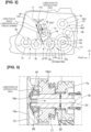
- Figure 2 a schematic diagram in which a case 13 in the first embodiment is viewed from an axial direction of a driveshaft 5.
- Fig. 2 illustrates meshing pitch circles for gears. Upward in the plane of the drawing shown in Fig. 2 is the same as upward in a vertical direction, and leftward in the plane of the drawing shown in Fig. 2 is the same as forward in a longitudinal direction of the vehicle.
- the electric-power-generating-motor gear train 7 and the travel-motor reduction mechanism 9 are accommodated in the case 13.
- the ring gear 10a of the differential 10, the second gear 12a2 and the internal-combustion-engine final reduction gear 12b of the internal-combustion-engine travel gear set 12, and the second gear 7b and the third gear 7c of the electric-power-generating-motor gear train 7 are disposed in a lowermost section of the case 13.
- Lowermost ends of the gears 10a, 12a2, 12b, 7b, 7c are positioned lower than an oil level OL of oil (referred to as "lubricating oil” below) that is retained in the lowermost section of the case 13.
- the oil level OL is set at a height at which substantially lower halves of the gears 10a, 12a2, 12b, 7b, 7c are continuously submerged.
- the gears 9a1, 9a2, 9b of the travel-motor reduction mechanism 9 are disposed at positions higher than the ring gear 10a.
- the first gear 9a1 is disposed at a position higher than the second gear 9a2 and the travel-motor final reduction gear 9b.
- the first gear 12a1 of the internal-combustion-engine travel gear set 12 and the first gear 7a of the electric-power-generating-motor gear train 7 are disposed at positions higher than the second gear 7b of the electric-power-generating-motor gear train 7 and the second gear 12a2 and internal-combustion-engine final reduction gear 12b of the internal-combustion-engine travel gear set 12.
- Lowermost ends of the gears 12a1, 7a are positioned higher than the oil level OL and are not submerged in the lubricating oil.
- a rotational center O2 of the second gear 12a2 and the internal-combustion-engine final reduction gear 12b is positioned lower than a straight line L1 that links a rotational center O1 of the first gear 12a1 and a rotational center O3 of the ring gear 10a as seen from a rotation-axis direction of the driveshaft 5.
- arrows drawn inside the pitch circles for the gears indicate directions of rotation when the vehicle advances. Because the second gear 12a2 and the internal-combustion-engine final reduction gear 12b are coupled by the rotating shaft 12c and have the same number of teeth, these gears are regarded as one intermediate gear 14.
- the intermediate gear 14 rotates in a clockwise direction in Fig. 2 . Specifically, the intermediate gear 14 rotates in a direction in which teeth 14a of the intermediate gear 14 that have passed through the lubricating oil stored inside the case 13 mesh with teeth 16 of the first gear 12a1 before teeth 15 of the ring gear 10a.
- An oil reservoir 17 is established in a left-side wall 13a of the case 13.
- the oil reservoir 17 projects toward an interior of the case 13 from the left-side wall 13a, and has a recessed shape in which an upper portion is open.
- the oil reservoir 17 is capable of retaining lubricating oil that has been thrust upward by the intermediate gear 14.
- the oil reservoir 17 has an opening 17a in a lowermost end thereof.
- an oil passage 18 is established below the oil reservoir 17.
- the oil passage 18 is a ridge that projects toward the interior of the case 13 from the left-side wall 13a. Lubricating oil that has dropped from the opening 17a is guided to a distal-end part of the input shaft 1b along the oil passage 18.
- Figure 3 is a transverse cross-sectional view of the input shaft 1b.
- a bearing 19 is established in the left-side wall 13a of the case 13.
- Ball bearings 20 are mounted in the bearing 19.
- the ball bearings 20 rotatably support the distal-end part of the input shaft 1b.
- a recess 19a that opens upward in the bearing 19 is established at a position facing a distal-end surface of the input shaft 1b.
- the lubricating oil flowing along the oil passage 18 is introduced into the recess 19a.
- the input shaft 1b has, in an interior thereof, a shaft core lubricating oil passage 21 and a plurality of diameter-direction oil passages 22.
- the shaft core lubricating oil passage 21 extends, in a direction following a rotational axis of the input shaft 1b, from the distal end of the input shaft 1b.
- the shaft core lubricating oil passage 21 communicates with the recess 19a.
- the diameter-direction oil passages 22 extend in a radial direction relative to a rotational center of the input shaft 1b, and allow the shaft core lubricating oil passage 21 and an outer peripheral surface of the input shaft 1b to communicate.
- Lubricating oil that has dropped into the recess 19a through the oil passage 18 is supplied to the shaft core lubricating oil passage 21 and is used to lubricate the first gear 7a and the first gear 12a1 upon passing through the diameter-direction oil passages 22 due to centrifugal force.
- the hybrid vehicle in the first embodiment has the internal-combustion-engine travel clutch 11 that can connect and disconnect a path along which drive force is inputted from the input shaft 1b to the first gear 12a1.
- releasing the internal-combustion-engine travel clutch 11 makes it possible to reduce the number of gears meshing under zero-load conditions at a site (internal-combustion-engine travel gear set 12) where a deviation has been made from the path (electric-power-generating-motor gear train 7) over which drive force is transferred to the electric-power-generating motor 2.
- a site internal-combustion-engine travel gear set 12
- a deviation has been made from the path (electric-power-generating-motor gear train 7) over which drive force is transferred to the electric-power-generating motor 2.
- rotation of the drive wheels 6 is transferred to the internal-combustion-engine travel gear set 12, zero-load conditions are not in effect. As a result, incidence of gear rattle associated with torque fluctuation of the internal combustion engine 1 can be suppressed.
- the first gear 12a1 continues to rotate in an un-assisted manner (co-rotates in association with the drive wheels 6), but because the first gear 12a1 is at a relatively high position and is set apart from the oil level OL of the lubricating oil stored inside the case 13, supplying the lubricating oil is a problem to be addressed.
- the rotational center O2 of the intermediate gear 14 (second gear 12a2 and internal-combustion-engine final reduction gear 12b) is positioned lower than a straight line L1 that links the rotational center O1 of the first gear 12a1 and the rotational center O3 of the ring gear 10a as seen from the rotation-axis direction of the driveshaft 5.
- a lowermost end of the intermediate gear 14 is positioned lower in the vertical direction than the lowermost end of the first gear 12a1. This results an increase in an area of the intermediate gear 14 coming into contact with the lubricating oil stored inside the case 13, and therefore, increases the amount of lubricating oil that is thrust upward and it is made possible to further improve lubricity of the first gear 12a1.
- the first gear 12a1 is lubricated only by lubricating oil that has been thrust upward by the intermediate gear 14. Specifically, a pump for pumping the lubricating oil to the first gear 12a1 is unnecessary, therefore avoiding incidence of motive power loss associated with actuation of such a pump.
- the intermediate gear 14 rotates in a direction in which the teeth 14a of the intermediate gear 14 that have passed through the lubricating oil stored inside the case 13 mesh with the teeth 16 of the first gear 12a1 before the teeth 15 of the ring gear 10a. Due to the intermediate gear 14 being configured to mesh with the first gear 12a1 before the ring gear 10a, the lubricating oil that has been thrust upward above the oil level OL by the intermediate gear 14 is flung toward the first gear 12a1 and makes it possible for more of the lubricating oil to be supplied to the first gear 12a1, therefore making it possible to further improve lubricity of the first gear 12a1.
- the oil reservoir 17, the oil passage 18, the recess 19a, the shaft core lubricating oil passage 21, and the plurality of diameter-direction oil passages 22 are provided as an oil passage for supplying the lubricating oil that has been thrust upward by the intermediate gear 14 to the first gear 12a1.
- usage efficiency of the lubricating oil that has been thrust upward by the intermediate gear 14 is raised.
- lubricity of the first gear 12a1 can be further improved.
- the lowermost end of the first gear 12a1 is positioned higher in the vertical direction that the oil level OL of the lubricating oil stored inside the case 13. This makes it possible to prevent worsening of motive power transmission efficiency associated with agitation of the lubricating oil by the first gear 12a1. In addition, generation of heat associated with agitation of the lubricating oil can be minimized, and excessive increases in temperature can be suppressed.
Landscapes
- Engineering & Computer Science (AREA)
- Mechanical Engineering (AREA)
- General Engineering & Computer Science (AREA)
- Transportation (AREA)
- Chemical & Material Sciences (AREA)
- Combustion & Propulsion (AREA)
- Automation & Control Theory (AREA)
- General Details Of Gearings (AREA)
- Hybrid Electric Vehicles (AREA)
- Soil Working Implements (AREA)
Description
- The present invention relates to a hybrid vehicle.
-
Patent Document 1 discloses a hybrid vehicle that can travel by switching between a series scheme and a parallel scheme. In the hybrid vehicle, a transmission device for realizing the parallel scheme is installed between an internal combustion engine and drive wheels. The transmission device has an input gear that connects to the internal combustion engine, an output gear that connects to the drive wheel, an intermediate gear that connects the input gear and the output gear, and a clutch that connects and disconnects a drive force transmission path between the internal combustion engine and the input gear.
EP3453549A1 describes a transaxle device for a hybrid vehicle including an engine, a first rotating electric machine, and a second rotating electric machine individually transmit the power of the engine and power of the first rotating electric machine to an output shaft on a drive wheel side and also transmits the power of the engine to the second rotating electric machine. Further, the transaxle device includes an input shaft which is coaxially connected to a rotating shaft of the engine and a switching mechanism which is interposed in at least the input shaft and switches a high gear stage and a low gear stage.
CN105584349B describes a transmission assembly for a hybrid electric vehicle. A first permanent magnet motor output shaft is connected with a first permanent magnet motor and provided with a first permanent magnet motor output shaft gear. An input shaft is provided with an input shaft gear engaged with the first permanent magnet motor output shaft gear. A first clutch, a needle bearing and a second intermediate shaft gear are assembled on an intermediate shaft. The needle bearing is sleeved with a first intermediate shaft gear in a spaced manner. The first intermediate shaft gear is connected with a first clutch gear hub and engaged with the input shaft gear. A main speed reduction gear is connected with a differential mechanism assembly. A sun gear of a planet gear disc assembly is an axial gear integrated with a second permanent magnet motor output shaft. A planet gear is supported on a planet carrier and engaged with the sun gear and a gear ring. A normally-engaged gear and the planet carrier are assembly on the second permanent magnet motor output shaft in an integrally-connected manner and engaged with the main speed reduction gear. A second clutch is arranged between the planet carrier and the gear ring. A second intermediate shaft gear is engaged with the main speed reduction gear. - Patent Document 1:
Japanese Patent No. 6202256 - In order for drive force from a high-volume internal combustion engine to be inputted, the input gear is established at a higher position relative to the other gears inside a case accommodating the transmission device. Therefore, the input gear is at a position higher than an oil level of the lubricating oil, and supplying the lubricating oil is a problem to be addressed. In this prior art hybrid vehicle, because the intermediate gear that meshes with the input gear is at a position higher than the input gear, thrusting the lubricating oil upward to lubricate the input gear has presented difficulties. It is an object of the present invention to provide a hybrid vehicle in which lubricity of an input gear can be improved.
- For achieving the above object, the present invention provides a hybrid vehicle as defined in
claim 1. Further advantageous effects can be achieved by preferred embodiments defined in the appended dependent claims. - This makes it possible for lubricating oil that has been thrust upward by the intermediate gear to be supplied to the input gear, therefore making it possible to improve lubricity of the input gear.
-
-
Figure 1 is a schematic diagram showing a drive system of a hybrid vehicle in accordance with a first embodiment; -
Figure 2 is a schematic diagram in which acase 13 of the first embodiment is viewed from an axial direction of adriveshaft 5; and -
Figure 3 is a transverse cross-sectional view of aninput shaft 1b. -
- 1
- Internal combustion engine
- 2
- Electric-power-generating motor (electric-power generator)
- 3
- Travel motor (electric motor)
- 6
- Drive wheel
- 10a
- Ring gear (output gear)
- 11
- Internal-combustion-engine travel clutch (connection-disconnection device)
- 12a1
- First gear (input gear)
- 12a2
- Second gear (intermediate gear)
- 12b
- Internal-combustion-engine final reduction gear (intermediate gear)
- 13
- Case
- 14
- Intermediate gear
-
Figure 1 is a schematic diagram showing a drive system of a hybrid vehicle in a first embodiment. The hybrid vehicle in the first embodiment has an internal combustion engine (engine) 1, an electric-power-generating motor (electric-power generator) 2, a travel motor (electric motor) 3, atransmission device 4,driveshafts 5, anddrive wheels 6. Acrankshaft 1a of theinternal combustion engine 1 is coupled with aninput shaft 1b. Theinput shaft 1b is coupled with amotor shaft 2a of the electric-power-generatingmotor 2 via an electric-power-generating-motor gear train 7. The electric-power-generating-motor gear train 7 has threegears first gear 7a rotates integrally with theinput shaft 1b. Thethird gear 7c rotates integrally with themotor shaft 2a. Thesecond gear 7b meshes with each of thefirst gear 7a and thethird gear 7c. - A
motor shaft 3a of thetravel motor 3 is coupled with a travel-motor reduction mechanism 9 via amotor travel clutch 8. The travel-motor reduction mechanism 9 has a travel-motor gear train 9a and a travel-motorfinal reduction gear 9b. The travel-motor gear train 9a has two gears 9a1, 9a2 that mesh with each other. The first gear 9a1 is coupled with one engagement element in themotor travel clutch 8. Another engagement element is coupled with themotor shaft 3a. The second gear 9a2 is joined to the travel-motorfinal reduction gear 9b by arotating shaft 9c. The travel-motorfinal reduction gear 9b meshes with a ring gear (output gear) 10a of a differential 10 in thetransmission device 4. Releasing themotor travel clutch 8 permits relative rotation between themotor shaft 3a and the first gear 9a1, and engaging themotor travel clutch 8 restricts relative rotation between themotor shaft 3a and the first gear 9a1. - In addition to the differential 10, the
transmission device 4 has an internal-combustion-engine travel clutch (connection-disconnection device) 11 and an internal-combustion-engine travel gear set 12. Releasing the internal-combustion-engine travel clutch 11 permits relative rotation between theinput shaft 1b and (a first gear 12a1 of) the internal-combustion-engine travel gear set 12, and engaging the internal-combustion-engine travel clutch 11 restricts relative rotation between theinput shaft 1b and the internal-combustion-engine travel gear set 12. The internal-combustion-engine travel gear set 12 has an internal-combustion-enginetravel gear train 12a and an internal-combustion-enginefinal reduction gear 12b. The internal-combustion-enginetravel gear train 12a has two gears 12a1, 12a2 that mesh with each other. The first gear (input gear) 12a1 is coupled with one engagement element in the internal-combustion-engine travel clutch 11. Another engagement element is coupled with theinput shaft 1b. The second gear 12a2 is joined to the internal-combustion-enginefinal reduction gear 12b by arotating shaft 12c. The internal-combustion-enginefinal reduction gear 12b meshes with thering gear 10a. In addition to thering gear 10a, the differential 10 has adifferential case 10b having an actuating mechanism unit (not shown) in an interior thereof. Left/right side gears of the actuating mechanism unit are joined to left/right driveshafts 5. The left/right driveshafts 5 are joined to thedrive wheels 6. - In the hybrid vehicle in the first embodiment, engaging the
motor travel clutch 8 and releasing the internal-combustion-engine travel clutch 11 effects travel under a series hybrid mode in which only thetravel motor 3 is used as a motive power source for travel and theinternal combustion engine 1 is used as a motive power source for electric-power generation. In addition, releasing themotor travel clutch 8 and engaging the internal-combustion-engine travel clutch 11 effects travel under an internal-combustion-engine direct coupling mode in which only theinternal combustion engine 1 is used as a motive power source for travel. Engaging both of the twoclutches -
Figure 2 a schematic diagram in which acase 13 in the first embodiment is viewed from an axial direction of adriveshaft 5.Fig. 2 illustrates meshing pitch circles for gears. Upward in the plane of the drawing shown inFig. 2 is the same as upward in a vertical direction, and leftward in the plane of the drawing shown inFig. 2 is the same as forward in a longitudinal direction of the vehicle. In addition to the constituent elements of the transmission device 4 (i.e., the differential 10, the internal-combustion-engine travel clutch 11, and the internal-combustion-engine travel gear set 12), the electric-power-generating-motor gear train 7 and the travel-motor reduction mechanism 9 are accommodated in thecase 13. Thering gear 10a of the differential 10, the second gear 12a2 and the internal-combustion-enginefinal reduction gear 12b of the internal-combustion-engine travel gear set 12, and thesecond gear 7b and thethird gear 7c of the electric-power-generating-motor gear train 7 are disposed in a lowermost section of thecase 13. Lowermost ends of thegears 10a, 12a2, 12b, 7b, 7c are positioned lower than an oil level OL of oil (referred to as "lubricating oil" below) that is retained in the lowermost section of thecase 13. The oil level OL is set at a height at which substantially lower halves of thegears 10a, 12a2, 12b, 7b, 7c are continuously submerged. - The gears 9a1, 9a2, 9b of the travel-
motor reduction mechanism 9 are disposed at positions higher than thering gear 10a. The first gear 9a1 is disposed at a position higher than the second gear 9a2 and the travel-motorfinal reduction gear 9b. The first gear 12a1 of the internal-combustion-engine travel gear set 12 and thefirst gear 7a of the electric-power-generating-motor gear train 7 are disposed at positions higher than thesecond gear 7b of the electric-power-generating-motor gear train 7 and the second gear 12a2 and internal-combustion-enginefinal reduction gear 12b of the internal-combustion-engine travel gear set 12. Lowermost ends of the gears 12a1, 7a are positioned higher than the oil level OL and are not submerged in the lubricating oil. A rotational center O2 of the second gear 12a2 and the internal-combustion-enginefinal reduction gear 12b is positioned lower than a straight line L1 that links a rotational center O1 of the first gear 12a1 and a rotational center O3 of thering gear 10a as seen from a rotation-axis direction of thedriveshaft 5. - In
Fig. 2 , arrows drawn inside the pitch circles for the gears indicate directions of rotation when the vehicle advances. Because the second gear 12a2 and the internal-combustion-enginefinal reduction gear 12b are coupled by therotating shaft 12c and have the same number of teeth, these gears are regarded as one intermediate gear 14. The intermediate gear 14 rotates in a clockwise direction inFig. 2 . Specifically, the intermediate gear 14 rotates in a direction in whichteeth 14a of the intermediate gear 14 that have passed through the lubricating oil stored inside thecase 13 mesh withteeth 16 of the first gear 12a1 beforeteeth 15 of thering gear 10a. - An
oil reservoir 17 is established in a left-side wall 13a of thecase 13. Theoil reservoir 17 projects toward an interior of thecase 13 from the left-side wall 13a, and has a recessed shape in which an upper portion is open. Theoil reservoir 17 is capable of retaining lubricating oil that has been thrust upward by the intermediate gear 14. Theoil reservoir 17 has anopening 17a in a lowermost end thereof. In the left-side wall 13a, anoil passage 18 is established below theoil reservoir 17. Theoil passage 18 is a ridge that projects toward the interior of thecase 13 from the left-side wall 13a. Lubricating oil that has dropped from theopening 17a is guided to a distal-end part of theinput shaft 1b along theoil passage 18. -
Figure 3 is a transverse cross-sectional view of theinput shaft 1b. Abearing 19 is established in the left-side wall 13a of thecase 13.Ball bearings 20 are mounted in thebearing 19. Theball bearings 20 rotatably support the distal-end part of theinput shaft 1b. Arecess 19a that opens upward in thebearing 19 is established at a position facing a distal-end surface of theinput shaft 1b. The lubricating oil flowing along theoil passage 18 is introduced into therecess 19a. Theinput shaft 1b has, in an interior thereof, a shaft core lubricatingoil passage 21 and a plurality of diameter-direction oil passages 22. The shaft core lubricatingoil passage 21 extends, in a direction following a rotational axis of theinput shaft 1b, from the distal end of theinput shaft 1b. The shaft core lubricatingoil passage 21 communicates with therecess 19a. The diameter-direction oil passages 22 extend in a radial direction relative to a rotational center of theinput shaft 1b, and allow the shaft core lubricatingoil passage 21 and an outer peripheral surface of theinput shaft 1b to communicate. Lubricating oil that has dropped into therecess 19a through theoil passage 18 is supplied to the shaft core lubricatingoil passage 21 and is used to lubricate thefirst gear 7a and the first gear 12a1 upon passing through the diameter-direction oil passages 22 due to centrifugal force. - Effects of the first embodiment are described next. The hybrid vehicle in the first embodiment has the internal-combustion-
engine travel clutch 11 that can connect and disconnect a path along which drive force is inputted from theinput shaft 1b to the first gear 12a1. In series hybrid mode, releasing the internal-combustion-engine travel clutch 11 makes it possible to reduce the number of gears meshing under zero-load conditions at a site (internal-combustion-engine travel gear set 12) where a deviation has been made from the path (electric-power-generating-motor gear train 7) over which drive force is transferred to the electric-power-generatingmotor 2. Specifically, because rotation of thedrive wheels 6 is transferred to the internal-combustion-engine travel gear set 12, zero-load conditions are not in effect. As a result, incidence of gear rattle associated with torque fluctuation of theinternal combustion engine 1 can be suppressed. - However, a volume of the
internal combustion engine 1 is high, and a vertical-direction position of thecrankshaft 1a will tend to be relatively higher than thedriveshafts 5, etc. Therefore, even the first gear 12a1 of the internal-combustion-engine travel gear set 12 to which drive force is inputted from theinternal combustion engine 1 is established inside thecase 13 of thetransmission device 4 at a position that is relatively higher than thering gear 10a, etc. In series hybrid mode, the first gear 12a1 continues to rotate in an un-assisted manner (co-rotates in association with the drive wheels 6), but because the first gear 12a1 is at a relatively high position and is set apart from the oil level OL of the lubricating oil stored inside thecase 13, supplying the lubricating oil is a problem to be addressed. - However, in the hybrid vehicle in the first embodiment, the rotational center O2 of the intermediate gear 14 (second gear 12a2 and internal-combustion-engine
final reduction gear 12b) is positioned lower than a straight line L1 that links the rotational center O1 of the first gear 12a1 and the rotational center O3 of thering gear 10a as seen from the rotation-axis direction of thedriveshaft 5. This results in some of the lubricating oil that has been thrust upward above the oil level OL by the intermediate gear 14 being flung toward the first gear 12a1 and makes it possible to for the lubricating oil to be supplied to the first gear 12a1, therefore making it possible to improve lubricity of the first gear 12a1. - A lowermost end of the intermediate gear 14 is positioned lower in the vertical direction than the lowermost end of the first gear 12a1. This results an increase in an area of the intermediate gear 14 coming into contact with the lubricating oil stored inside the
case 13, and therefore, increases the amount of lubricating oil that is thrust upward and it is made possible to further improve lubricity of the first gear 12a1. - The first gear 12a1 is lubricated only by lubricating oil that has been thrust upward by the intermediate gear 14. Specifically, a pump for pumping the lubricating oil to the first gear 12a1 is unnecessary, therefore avoiding incidence of motive power loss associated with actuation of such a pump.
- The intermediate gear 14 rotates in a direction in which the
teeth 14a of the intermediate gear 14 that have passed through the lubricating oil stored inside thecase 13 mesh with theteeth 16 of the first gear 12a1 before theteeth 15 of thering gear 10a. Due to the intermediate gear 14 being configured to mesh with the first gear 12a1 before thering gear 10a, the lubricating oil that has been thrust upward above the oil level OL by the intermediate gear 14 is flung toward the first gear 12a1 and makes it possible for more of the lubricating oil to be supplied to the first gear 12a1, therefore making it possible to further improve lubricity of the first gear 12a1. - The
oil reservoir 17, theoil passage 18, therecess 19a, the shaft core lubricatingoil passage 21, and the plurality of diameter-direction oil passages 22 are provided as an oil passage for supplying the lubricating oil that has been thrust upward by the intermediate gear 14 to the first gear 12a1. This makes it possible for some of the lubricating oil that has been thrust upward by the intermediate gear 14 and has not adhered to the first gear 12a1 to be used in lubricating the first gear 12a1. As a result, usage efficiency of the lubricating oil that has been thrust upward by the intermediate gear 14 is raised. In addition, lubricity of the first gear 12a1 can be further improved. - The lowermost end of the first gear 12a1 is positioned higher in the vertical direction that the oil level OL of the lubricating oil stored inside the
case 13. This makes it possible to prevent worsening of motive power transmission efficiency associated with agitation of the lubricating oil by the first gear 12a1. In addition, generation of heat associated with agitation of the lubricating oil can be minimized, and excessive increases in temperature can be suppressed. - A mode for carrying out the present invention has been described above on the basis of the embodiment, but the specific configuration of the present invention is not limited to this embodiment; design changes, etc., that do not depart from the scope of the invention, as defined in the appended claims, are also included in the present invention.
Claims (6)
- A hybrid vehicle comprising:an internal combustion engine (1);an electric-power generator (2) that receives a drive force generated by the internal combustion engine (1) and generates electric power;an electric motor (3) that receives a supply of electric power generated by the electric-power generator (2) and drives a drive wheel (6);a transmission device (4) that transmits the drive force generated by the internal combustion engine (1) to the drive wheel (6), the transmission device (4) having an input gear (12a1), an output gear (10a), an intermediate gear (14) and a connection-disconnection device (11),the input gear (12a1) being configured to receive the drive force as an input from the internal combustion engine (1),the output gear (10a) being configured to output the drive force to the drive wheel (6),the intermediate gear (14) being configured to transmit the drive force between the input gear (12a1) and the output gear (10a),the connection-disconnection device (11) being configured to switch between connecting and disconnecting a path along which the drive force is inputted to the input gear (12a1), anda rotational center (O2) of the intermediate gear (14) being positioned lower in a vertical direction than a straight line (L1) that links a rotational center (O1) of the input gear (12a1) and a rotational center (O3) of the output gear (10a) as seen from an axial direction, where the axial direction is a direction along a rotational axis of the intermediate gear (14);characterised in that the hybrid vehicle further comprises:a second transmission device (7) that transmits the drive force generated by the internal combustion engine (1) to the electric-power generator (2), the second transmission device (7) having a second input gear (7a), a second output gear (7c) and a second intermediate gear (7b),the second input gear (7a) arranged to rotate integrally with an input shaft (1b) of the transmission device (4),the second output gear (7c) configured to rotate integrally with a motor shaft (2a) of the electric-power generator (2), andthe second intermediate gear (7b) arranged to mesh with the second input gear (7a) and the second output gear (7c); anda case (13) that accommodates the input gear (12a1), the intermediate gear (14), the output gear (10a), the second input gear (7a), the second output gear (7c), and the second intermediate gear (7b),lowermost ends of the output gear (10a), the intermediate gear (14), the second intermediate gear (7b), and the second output gear (7c) being positioned lower in the vertical direction than an oil level (OL) of lubricating oil disposed inside the case (13).
- The hybrid vehicle according to claim 1, wherein
a lowermost end of the intermediate gear (14) is positioned lower in the vertical direction than a lowermost end of the input gear (12a1). - The hybrid vehicle according to claim 1 or 2, wherein
the input gear (12a1) is lubricated only by lubricating oil that has been thrust upward by the intermediate gear (14). - The hybrid vehicle according to any of claims 1 to 3, wherein
The intermediate gear (14) is configured to rotate in a direction in which teeth of the intermediate gear (14) that have passed through lubricating oil stored inside the case (13) mesh with teeth of the input gear (12a1) before meshing with teeth of the output gear (10a). - The hybrid vehicle according to any of claims 1 to 4, further comprising
an oil passage for supplying lubricating oil that has been thrust upward by the intermediate gear (14) to the input gear (12a1). - The hybrid vehicle according to any of claims 1 to 5, wherein
a lowermost end of the input gear (12a1) is positioned higher in the vertical direction than an oil level (OL) of lubricating oil stored inside the case (13).
Applications Claiming Priority (1)
| Application Number | Priority Date | Filing Date | Title |
|---|---|---|---|
| PCT/JP2018/037400 WO2020070881A1 (en) | 2018-10-05 | 2018-10-05 | Hybrid vehicle |
Publications (3)
| Publication Number | Publication Date |
|---|---|
| EP3862206A1 EP3862206A1 (en) | 2021-08-11 |
| EP3862206A4 EP3862206A4 (en) | 2021-10-27 |
| EP3862206B1 true EP3862206B1 (en) | 2024-02-14 |
Family
ID=70055366
Family Applications (1)
| Application Number | Title | Priority Date | Filing Date |
|---|---|---|---|
| EP18936018.3A Active EP3862206B1 (en) | 2018-10-05 | 2018-10-05 | Hybrid vehicle |
Country Status (5)
| Country | Link |
|---|---|
| US (1) | US12036974B2 (en) |
| EP (1) | EP3862206B1 (en) |
| JP (1) | JP7004081B2 (en) |
| CN (1) | CN112789187B (en) |
| WO (1) | WO2020070881A1 (en) |
Families Citing this family (1)
| Publication number | Priority date | Publication date | Assignee | Title |
|---|---|---|---|---|
| US12241540B2 (en) * | 2022-06-10 | 2025-03-04 | Allison Transmission, Inc. | Sealed cover with nozzle |
Family Cites Families (19)
| Publication number | Priority date | Publication date | Assignee | Title |
|---|---|---|---|---|
| JPS595937A (en) | 1982-07-02 | 1984-01-12 | Meidensha Electric Mfg Co Ltd | Measurement of oil mist density |
| JP4539531B2 (en) * | 2005-10-26 | 2010-09-08 | トヨタ自動車株式会社 | Vehicle drive device |
| JP4466685B2 (en) * | 2007-06-19 | 2010-05-26 | トヨタ自動車株式会社 | Power transmission device for vehicle |
| JP4369966B2 (en) * | 2007-07-18 | 2009-11-25 | アイシン・エィ・ダブリュ株式会社 | Hybrid vehicle drive device |
| WO2009128288A1 (en) * | 2008-04-14 | 2009-10-22 | 本田技研工業株式会社 | Hybrid vehicle drive unit |
| JP2010038326A (en) | 2008-08-07 | 2010-02-18 | Toyota Motor Corp | Power transmission device |
| JP4743241B2 (en) * | 2008-08-29 | 2011-08-10 | トヨタ自動車株式会社 | Power transmission device |
| JP2010144825A (en) * | 2008-12-18 | 2010-07-01 | Jtekt Corp | Vehicular steering unit |
| JP4770947B2 (en) * | 2009-03-02 | 2011-09-14 | トヨタ自動車株式会社 | Vehicle power transmission device |
| JP5747781B2 (en) * | 2011-10-20 | 2015-07-15 | トヨタ自動車株式会社 | Lubricating oil supply device for power transmission system |
| EP2937237B1 (en) * | 2012-12-21 | 2021-08-11 | Nissan Motor Co., Ltd. | Hybrid vehicle drive device |
| JP6079519B2 (en) * | 2013-09-11 | 2017-02-15 | アイシン・エィ・ダブリュ株式会社 | Vehicle drive device |
| JP6202256B2 (en) | 2013-06-28 | 2017-09-27 | 三菱自動車工業株式会社 | Vehicle transaxle device |
| JP6070522B2 (en) * | 2013-11-27 | 2017-02-01 | アイシン・エィ・ダブリュ株式会社 | Vehicle drive device |
| CN105584349B (en) * | 2016-02-04 | 2018-02-09 | 重庆青山工业有限责任公司 | A kind of hybrid-powered motor speed variator assembly |
| JP6819083B2 (en) * | 2016-06-13 | 2021-01-27 | 三菱自動車工業株式会社 | Transaxle device |
| US10807457B2 (en) * | 2016-06-13 | 2020-10-20 | Mitsubishi Jidosha Kogyo Kabushiki Kaisha | Transaxle device for hybrid vehicle having connection/disconnection mechanism that enables or disables transmission of power of electric machine |
| JP6137429B1 (en) * | 2017-01-17 | 2017-05-31 | トヨタ自動車株式会社 | Hybrid vehicle |
| CN108128135A (en) * | 2017-12-20 | 2018-06-08 | 东风汽车集团有限公司 | A kind of power assembly arrangement of hybrid vehicle |
-
2018
- 2018-10-05 WO PCT/JP2018/037400 patent/WO2020070881A1/en not_active Ceased
- 2018-10-05 JP JP2020551055A patent/JP7004081B2/en active Active
- 2018-10-05 EP EP18936018.3A patent/EP3862206B1/en active Active
- 2018-10-05 US US17/273,746 patent/US12036974B2/en active Active
- 2018-10-05 CN CN201880098197.3A patent/CN112789187B/en active Active
Also Published As
| Publication number | Publication date |
|---|---|
| CN112789187B (en) | 2024-07-02 |
| CN112789187A (en) | 2021-05-11 |
| EP3862206A1 (en) | 2021-08-11 |
| US20210323534A1 (en) | 2021-10-21 |
| JPWO2020070881A1 (en) | 2021-09-02 |
| WO2020070881A1 (en) | 2020-04-09 |
| EP3862206A4 (en) | 2021-10-27 |
| JP7004081B2 (en) | 2022-01-21 |
| US12036974B2 (en) | 2024-07-16 |
Similar Documents
| Publication | Publication Date | Title |
|---|---|---|
| CN112449739B (en) | Electric driver with cooling function | |
| CN106794749B (en) | Gear arrangement | |
| US4479404A (en) | Concentric powertrain for electric vehicle | |
| US4418777A (en) | Transmission lubrication and motor cooling system | |
| JP6457787B2 (en) | Transmission device for hybrid vehicle | |
| JP4218129B2 (en) | Hydraulic pressure generator and hybrid vehicle using the same | |
| JP4234947B2 (en) | Drive unit for hydraulic pressure generator | |
| US8013483B2 (en) | Hybrid drive device | |
| US12441175B2 (en) | Drive unit and drive assembly | |
| JP2018105419A (en) | Hybrid vehicle lubrication structure | |
| CN112334345A (en) | A drive unit for a drive train of an electrically driven motor vehicle and a drive device having the same | |
| CN111173917A (en) | Cooling device for power transmission device | |
| CN106133401B (en) | Lubrication structure of transmission | |
| CN107848391A (en) | Vehicle driving apparatus | |
| KR102710232B1 (en) | Drive Units and Drive Devices | |
| KR102679352B1 (en) | Drive units and drive assemblies for powertrains of electric vehicles | |
| JP2018048679A (en) | Gear device | |
| CN109305028B (en) | Hybrid transmission with dual drive pumps | |
| JP2004353780A (en) | Vehicle drive device and FR-type hybrid vehicle equipped with the vehicle drive device | |
| EP3862206B1 (en) | Hybrid vehicle | |
| JP3867651B2 (en) | Lubrication structure of power transmission device | |
| JP2016094944A (en) | Vehicular drive device | |
| US20260063198A1 (en) | Transaxle | |
| JP7729183B2 (en) | Motor lubrication structure | |
| CN112440726B (en) | Turbine-mounted P2 front wheel drive transmission structure |
Legal Events
| Date | Code | Title | Description |
|---|---|---|---|
| STAA | Information on the status of an ep patent application or granted ep patent |
Free format text: STATUS: THE INTERNATIONAL PUBLICATION HAS BEEN MADE |
|
| PUAI | Public reference made under article 153(3) epc to a published international application that has entered the european phase |
Free format text: ORIGINAL CODE: 0009012 |
|
| STAA | Information on the status of an ep patent application or granted ep patent |
Free format text: STATUS: REQUEST FOR EXAMINATION WAS MADE |
|
| 17P | Request for examination filed |
Effective date: 20210430 |
|
| AK | Designated contracting states |
Kind code of ref document: A1 Designated state(s): AL AT BE BG CH CY CZ DE DK EE ES FI FR GB GR HR HU IE IS IT LI LT LU LV MC MK MT NL NO PL PT RO RS SE SI SK SM TR |
|
| A4 | Supplementary search report drawn up and despatched |
Effective date: 20210928 |
|
| RIC1 | Information provided on ipc code assigned before grant |
Ipc: B60K 6/442 20071001ALI20210922BHEP Ipc: B60K 6/40 20071001ALI20210922BHEP Ipc: B60K 6/36 20071001AFI20210922BHEP |
|
| DAV | Request for validation of the european patent (deleted) | ||
| DAX | Request for extension of the european patent (deleted) | ||
| STAA | Information on the status of an ep patent application or granted ep patent |
Free format text: STATUS: EXAMINATION IS IN PROGRESS |
|
| 17Q | First examination report despatched |
Effective date: 20220913 |
|
| GRAP | Despatch of communication of intention to grant a patent |
Free format text: ORIGINAL CODE: EPIDOSNIGR1 |
|
| STAA | Information on the status of an ep patent application or granted ep patent |
Free format text: STATUS: GRANT OF PATENT IS INTENDED |
|
| GRAS | Grant fee paid |
Free format text: ORIGINAL CODE: EPIDOSNIGR3 |
|
| INTG | Intention to grant announced |
Effective date: 20231211 |
|
| GRAA | (expected) grant |
Free format text: ORIGINAL CODE: 0009210 |
|
| STAA | Information on the status of an ep patent application or granted ep patent |
Free format text: STATUS: THE PATENT HAS BEEN GRANTED |
|
| AK | Designated contracting states |
Kind code of ref document: B1 Designated state(s): AL AT BE BG CH CY CZ DE DK EE ES FI FR GB GR HR HU IE IS IT LI LT LU LV MC MK MT NL NO PL PT RO RS SE SI SK SM TR |
|
| REG | Reference to a national code |
Ref country code: GB Ref legal event code: FG4D |
|
| REG | Reference to a national code |
Ref country code: CH Ref legal event code: EP |
|
| REG | Reference to a national code |
Ref country code: DE Ref legal event code: R096 Ref document number: 602018065404 Country of ref document: DE |
|
| REG | Reference to a national code |
Ref country code: IE Ref legal event code: FG4D |
|
| REG | Reference to a national code |
Ref country code: LT Ref legal event code: MG9D |
|
| REG | Reference to a national code |
Ref country code: NL Ref legal event code: MP Effective date: 20240214 |
|
| PG25 | Lapsed in a contracting state [announced via postgrant information from national office to epo] |
Ref country code: IS Free format text: LAPSE BECAUSE OF FAILURE TO SUBMIT A TRANSLATION OF THE DESCRIPTION OR TO PAY THE FEE WITHIN THE PRESCRIBED TIME-LIMIT Effective date: 20240614 |
|
| PG25 | Lapsed in a contracting state [announced via postgrant information from national office to epo] |
Ref country code: LT Free format text: LAPSE BECAUSE OF FAILURE TO SUBMIT A TRANSLATION OF THE DESCRIPTION OR TO PAY THE FEE WITHIN THE PRESCRIBED TIME-LIMIT Effective date: 20240214 |
|
| PG25 | Lapsed in a contracting state [announced via postgrant information from national office to epo] |
Ref country code: GR Free format text: LAPSE BECAUSE OF FAILURE TO SUBMIT A TRANSLATION OF THE DESCRIPTION OR TO PAY THE FEE WITHIN THE PRESCRIBED TIME-LIMIT Effective date: 20240515 |
|
| REG | Reference to a national code |
Ref country code: AT Ref legal event code: MK05 Ref document number: 1656764 Country of ref document: AT Kind code of ref document: T Effective date: 20240214 |
|
| PG25 | Lapsed in a contracting state [announced via postgrant information from national office to epo] |
Ref country code: HR Free format text: LAPSE BECAUSE OF FAILURE TO SUBMIT A TRANSLATION OF THE DESCRIPTION OR TO PAY THE FEE WITHIN THE PRESCRIBED TIME-LIMIT Effective date: 20240214 Ref country code: RS Free format text: LAPSE BECAUSE OF FAILURE TO SUBMIT A TRANSLATION OF THE DESCRIPTION OR TO PAY THE FEE WITHIN THE PRESCRIBED TIME-LIMIT Effective date: 20240514 Ref country code: NL Free format text: LAPSE BECAUSE OF FAILURE TO SUBMIT A TRANSLATION OF THE DESCRIPTION OR TO PAY THE FEE WITHIN THE PRESCRIBED TIME-LIMIT Effective date: 20240214 |
|
| PG25 | Lapsed in a contracting state [announced via postgrant information from national office to epo] |
Ref country code: ES Free format text: LAPSE BECAUSE OF FAILURE TO SUBMIT A TRANSLATION OF THE DESCRIPTION OR TO PAY THE FEE WITHIN THE PRESCRIBED TIME-LIMIT Effective date: 20240214 |
|
| PG25 | Lapsed in a contracting state [announced via postgrant information from national office to epo] |
Ref country code: AT Free format text: LAPSE BECAUSE OF FAILURE TO SUBMIT A TRANSLATION OF THE DESCRIPTION OR TO PAY THE FEE WITHIN THE PRESCRIBED TIME-LIMIT Effective date: 20240214 |
|
| PG25 | Lapsed in a contracting state [announced via postgrant information from national office to epo] |
Ref country code: RS Free format text: LAPSE BECAUSE OF FAILURE TO SUBMIT A TRANSLATION OF THE DESCRIPTION OR TO PAY THE FEE WITHIN THE PRESCRIBED TIME-LIMIT Effective date: 20240514 Ref country code: NO Free format text: LAPSE BECAUSE OF FAILURE TO SUBMIT A TRANSLATION OF THE DESCRIPTION OR TO PAY THE FEE WITHIN THE PRESCRIBED TIME-LIMIT Effective date: 20240514 Ref country code: NL Free format text: LAPSE BECAUSE OF FAILURE TO SUBMIT A TRANSLATION OF THE DESCRIPTION OR TO PAY THE FEE WITHIN THE PRESCRIBED TIME-LIMIT Effective date: 20240214 Ref country code: LT Free format text: LAPSE BECAUSE OF FAILURE TO SUBMIT A TRANSLATION OF THE DESCRIPTION OR TO PAY THE FEE WITHIN THE PRESCRIBED TIME-LIMIT Effective date: 20240214 Ref country code: IS Free format text: LAPSE BECAUSE OF FAILURE TO SUBMIT A TRANSLATION OF THE DESCRIPTION OR TO PAY THE FEE WITHIN THE PRESCRIBED TIME-LIMIT Effective date: 20240614 Ref country code: HR Free format text: LAPSE BECAUSE OF FAILURE TO SUBMIT A TRANSLATION OF THE DESCRIPTION OR TO PAY THE FEE WITHIN THE PRESCRIBED TIME-LIMIT Effective date: 20240214 Ref country code: GR Free format text: LAPSE BECAUSE OF FAILURE TO SUBMIT A TRANSLATION OF THE DESCRIPTION OR TO PAY THE FEE WITHIN THE PRESCRIBED TIME-LIMIT Effective date: 20240515 Ref country code: FI Free format text: LAPSE BECAUSE OF FAILURE TO SUBMIT A TRANSLATION OF THE DESCRIPTION OR TO PAY THE FEE WITHIN THE PRESCRIBED TIME-LIMIT Effective date: 20240214 Ref country code: ES Free format text: LAPSE BECAUSE OF FAILURE TO SUBMIT A TRANSLATION OF THE DESCRIPTION OR TO PAY THE FEE WITHIN THE PRESCRIBED TIME-LIMIT Effective date: 20240214 Ref country code: BG Free format text: LAPSE BECAUSE OF FAILURE TO SUBMIT A TRANSLATION OF THE DESCRIPTION OR TO PAY THE FEE WITHIN THE PRESCRIBED TIME-LIMIT Effective date: 20240214 Ref country code: AT Free format text: LAPSE BECAUSE OF FAILURE TO SUBMIT A TRANSLATION OF THE DESCRIPTION OR TO PAY THE FEE WITHIN THE PRESCRIBED TIME-LIMIT Effective date: 20240214 |
|
| PG25 | Lapsed in a contracting state [announced via postgrant information from national office to epo] |
Ref country code: PL Free format text: LAPSE BECAUSE OF FAILURE TO SUBMIT A TRANSLATION OF THE DESCRIPTION OR TO PAY THE FEE WITHIN THE PRESCRIBED TIME-LIMIT Effective date: 20240214 Ref country code: PT Free format text: LAPSE BECAUSE OF FAILURE TO SUBMIT A TRANSLATION OF THE DESCRIPTION OR TO PAY THE FEE WITHIN THE PRESCRIBED TIME-LIMIT Effective date: 20240614 |
|
| PG25 | Lapsed in a contracting state [announced via postgrant information from national office to epo] |
Ref country code: SE Free format text: LAPSE BECAUSE OF FAILURE TO SUBMIT A TRANSLATION OF THE DESCRIPTION OR TO PAY THE FEE WITHIN THE PRESCRIBED TIME-LIMIT Effective date: 20240214 Ref country code: PT Free format text: LAPSE BECAUSE OF FAILURE TO SUBMIT A TRANSLATION OF THE DESCRIPTION OR TO PAY THE FEE WITHIN THE PRESCRIBED TIME-LIMIT Effective date: 20240614 Ref country code: PL Free format text: LAPSE BECAUSE OF FAILURE TO SUBMIT A TRANSLATION OF THE DESCRIPTION OR TO PAY THE FEE WITHIN THE PRESCRIBED TIME-LIMIT Effective date: 20240214 Ref country code: LV Free format text: LAPSE BECAUSE OF FAILURE TO SUBMIT A TRANSLATION OF THE DESCRIPTION OR TO PAY THE FEE WITHIN THE PRESCRIBED TIME-LIMIT Effective date: 20240214 |
|
| PG25 | Lapsed in a contracting state [announced via postgrant information from national office to epo] |
Ref country code: DK Free format text: LAPSE BECAUSE OF FAILURE TO SUBMIT A TRANSLATION OF THE DESCRIPTION OR TO PAY THE FEE WITHIN THE PRESCRIBED TIME-LIMIT Effective date: 20240214 |
|
| PG25 | Lapsed in a contracting state [announced via postgrant information from national office to epo] |
Ref country code: SM Free format text: LAPSE BECAUSE OF FAILURE TO SUBMIT A TRANSLATION OF THE DESCRIPTION OR TO PAY THE FEE WITHIN THE PRESCRIBED TIME-LIMIT Effective date: 20240214 |
|
| PGFP | Annual fee paid to national office [announced via postgrant information from national office to epo] |
Ref country code: GB Payment date: 20240919 Year of fee payment: 7 |
|
| PGFP | Annual fee paid to national office [announced via postgrant information from national office to epo] |
Ref country code: FR Payment date: 20240919 Year of fee payment: 7 |
|
| PG25 | Lapsed in a contracting state [announced via postgrant information from national office to epo] |
Ref country code: CZ Free format text: LAPSE BECAUSE OF FAILURE TO SUBMIT A TRANSLATION OF THE DESCRIPTION OR TO PAY THE FEE WITHIN THE PRESCRIBED TIME-LIMIT Effective date: 20240214 Ref country code: EE Free format text: LAPSE BECAUSE OF FAILURE TO SUBMIT A TRANSLATION OF THE DESCRIPTION OR TO PAY THE FEE WITHIN THE PRESCRIBED TIME-LIMIT Effective date: 20240214 |
|
| PG25 | Lapsed in a contracting state [announced via postgrant information from national office to epo] |
Ref country code: SK Free format text: LAPSE BECAUSE OF FAILURE TO SUBMIT A TRANSLATION OF THE DESCRIPTION OR TO PAY THE FEE WITHIN THE PRESCRIBED TIME-LIMIT Effective date: 20240214 |
|
| PG25 | Lapsed in a contracting state [announced via postgrant information from national office to epo] |
Ref country code: SM Free format text: LAPSE BECAUSE OF FAILURE TO SUBMIT A TRANSLATION OF THE DESCRIPTION OR TO PAY THE FEE WITHIN THE PRESCRIBED TIME-LIMIT Effective date: 20240214 Ref country code: SK Free format text: LAPSE BECAUSE OF FAILURE TO SUBMIT A TRANSLATION OF THE DESCRIPTION OR TO PAY THE FEE WITHIN THE PRESCRIBED TIME-LIMIT Effective date: 20240214 Ref country code: RO Free format text: LAPSE BECAUSE OF FAILURE TO SUBMIT A TRANSLATION OF THE DESCRIPTION OR TO PAY THE FEE WITHIN THE PRESCRIBED TIME-LIMIT Effective date: 20240214 Ref country code: EE Free format text: LAPSE BECAUSE OF FAILURE TO SUBMIT A TRANSLATION OF THE DESCRIPTION OR TO PAY THE FEE WITHIN THE PRESCRIBED TIME-LIMIT Effective date: 20240214 Ref country code: DK Free format text: LAPSE BECAUSE OF FAILURE TO SUBMIT A TRANSLATION OF THE DESCRIPTION OR TO PAY THE FEE WITHIN THE PRESCRIBED TIME-LIMIT Effective date: 20240214 Ref country code: CZ Free format text: LAPSE BECAUSE OF FAILURE TO SUBMIT A TRANSLATION OF THE DESCRIPTION OR TO PAY THE FEE WITHIN THE PRESCRIBED TIME-LIMIT Effective date: 20240214 |
|
| REG | Reference to a national code |
Ref country code: DE Ref legal event code: R097 Ref document number: 602018065404 Country of ref document: DE |
|
| PG25 | Lapsed in a contracting state [announced via postgrant information from national office to epo] |
Ref country code: IT Free format text: LAPSE BECAUSE OF FAILURE TO SUBMIT A TRANSLATION OF THE DESCRIPTION OR TO PAY THE FEE WITHIN THE PRESCRIBED TIME-LIMIT Effective date: 20240214 |
|
| PLBE | No opposition filed within time limit |
Free format text: ORIGINAL CODE: 0009261 |
|
| STAA | Information on the status of an ep patent application or granted ep patent |
Free format text: STATUS: NO OPPOSITION FILED WITHIN TIME LIMIT |
|
| PG25 | Lapsed in a contracting state [announced via postgrant information from national office to epo] |
Ref country code: IT Free format text: LAPSE BECAUSE OF FAILURE TO SUBMIT A TRANSLATION OF THE DESCRIPTION OR TO PAY THE FEE WITHIN THE PRESCRIBED TIME-LIMIT Effective date: 20240214 |
|
| PGFP | Annual fee paid to national office [announced via postgrant information from national office to epo] |
Ref country code: DE Payment date: 20240919 Year of fee payment: 7 |
|
| 26N | No opposition filed |
Effective date: 20241115 |
|
| PG25 | Lapsed in a contracting state [announced via postgrant information from national office to epo] |
Ref country code: SI Free format text: LAPSE BECAUSE OF FAILURE TO SUBMIT A TRANSLATION OF THE DESCRIPTION OR TO PAY THE FEE WITHIN THE PRESCRIBED TIME-LIMIT Effective date: 20240214 |
|
| REG | Reference to a national code |
Ref country code: CH Ref legal event code: PL |
|
| PG25 | Lapsed in a contracting state [announced via postgrant information from national office to epo] |
Ref country code: MC Free format text: LAPSE BECAUSE OF FAILURE TO SUBMIT A TRANSLATION OF THE DESCRIPTION OR TO PAY THE FEE WITHIN THE PRESCRIBED TIME-LIMIT Effective date: 20240214 |
|
| PG25 | Lapsed in a contracting state [announced via postgrant information from national office to epo] |
Ref country code: LU Free format text: LAPSE BECAUSE OF NON-PAYMENT OF DUE FEES Effective date: 20241005 Ref country code: BE Free format text: LAPSE BECAUSE OF NON-PAYMENT OF DUE FEES Effective date: 20241031 |
|
| PG25 | Lapsed in a contracting state [announced via postgrant information from national office to epo] |
Ref country code: CH Free format text: LAPSE BECAUSE OF NON-PAYMENT OF DUE FEES Effective date: 20241031 |
|
| REG | Reference to a national code |
Ref country code: BE Ref legal event code: MM Effective date: 20241031 |
|
| PG25 | Lapsed in a contracting state [announced via postgrant information from national office to epo] |
Ref country code: IE Free format text: LAPSE BECAUSE OF NON-PAYMENT OF DUE FEES Effective date: 20241005 |
|
| PG25 | Lapsed in a contracting state [announced via postgrant information from national office to epo] |
Ref country code: CY Free format text: LAPSE BECAUSE OF FAILURE TO SUBMIT A TRANSLATION OF THE DESCRIPTION OR TO PAY THE FEE WITHIN THE PRESCRIBED TIME-LIMIT; INVALID AB INITIO Effective date: 20181005 |
|
| PG25 | Lapsed in a contracting state [announced via postgrant information from national office to epo] |
Ref country code: HU Free format text: LAPSE BECAUSE OF FAILURE TO SUBMIT A TRANSLATION OF THE DESCRIPTION OR TO PAY THE FEE WITHIN THE PRESCRIBED TIME-LIMIT; INVALID AB INITIO Effective date: 20181005 |