EP3862163A1 - Method for producing a foam component - Google Patents
Method for producing a foam component Download PDFInfo
- Publication number
- EP3862163A1 EP3862163A1 EP21155775.6A EP21155775A EP3862163A1 EP 3862163 A1 EP3862163 A1 EP 3862163A1 EP 21155775 A EP21155775 A EP 21155775A EP 3862163 A1 EP3862163 A1 EP 3862163A1
- Authority
- EP
- European Patent Office
- Prior art keywords
- mold
- starting material
- foam component
- foam
- pressure
- Prior art date
- Legal status (The legal status is an assumption and is not a legal conclusion. Google has not performed a legal analysis and makes no representation as to the accuracy of the status listed.)
- Granted
Links
Images


Classifications
-
- B—PERFORMING OPERATIONS; TRANSPORTING
- B29—WORKING OF PLASTICS; WORKING OF SUBSTANCES IN A PLASTIC STATE IN GENERAL
- B29C—SHAPING OR JOINING OF PLASTICS; SHAPING OF MATERIAL IN A PLASTIC STATE, NOT OTHERWISE PROVIDED FOR; AFTER-TREATMENT OF THE SHAPED PRODUCTS, e.g. REPAIRING
- B29C44/00—Shaping by internal pressure generated in the material, e.g. swelling or foaming ; Producing porous or cellular expanded plastics articles
- B29C44/02—Shaping by internal pressure generated in the material, e.g. swelling or foaming ; Producing porous or cellular expanded plastics articles for articles of definite length, i.e. discrete articles
-
- B—PERFORMING OPERATIONS; TRANSPORTING
- B29—WORKING OF PLASTICS; WORKING OF SUBSTANCES IN A PLASTIC STATE IN GENERAL
- B29C—SHAPING OR JOINING OF PLASTICS; SHAPING OF MATERIAL IN A PLASTIC STATE, NOT OTHERWISE PROVIDED FOR; AFTER-TREATMENT OF THE SHAPED PRODUCTS, e.g. REPAIRING
- B29C44/00—Shaping by internal pressure generated in the material, e.g. swelling or foaming ; Producing porous or cellular expanded plastics articles
- B29C44/34—Auxiliary operations
- B29C44/3492—Expanding without a foaming agent
-
- C—CHEMISTRY; METALLURGY
- C08—ORGANIC MACROMOLECULAR COMPOUNDS; THEIR PREPARATION OR CHEMICAL WORKING-UP; COMPOSITIONS BASED THEREON
- C08J—WORKING-UP; GENERAL PROCESSES OF COMPOUNDING; AFTER-TREATMENT NOT COVERED BY SUBCLASSES C08B, C08C, C08F, C08G or C08H
- C08J9/00—Working-up of macromolecular substances to porous or cellular articles or materials; After-treatment thereof
- C08J9/34—Chemical features in the manufacture of articles consisting of a foamed macromolecular core and a macromolecular surface layer having a higher density than the core
-
- B—PERFORMING OPERATIONS; TRANSPORTING
- B29—WORKING OF PLASTICS; WORKING OF SUBSTANCES IN A PLASTIC STATE IN GENERAL
- B29C—SHAPING OR JOINING OF PLASTICS; SHAPING OF MATERIAL IN A PLASTIC STATE, NOT OTHERWISE PROVIDED FOR; AFTER-TREATMENT OF THE SHAPED PRODUCTS, e.g. REPAIRING
- B29C44/00—Shaping by internal pressure generated in the material, e.g. swelling or foaming ; Producing porous or cellular expanded plastics articles
- B29C44/02—Shaping by internal pressure generated in the material, e.g. swelling or foaming ; Producing porous or cellular expanded plastics articles for articles of definite length, i.e. discrete articles
- B29C44/04—Shaping by internal pressure generated in the material, e.g. swelling or foaming ; Producing porous or cellular expanded plastics articles for articles of definite length, i.e. discrete articles consisting of at least two parts of chemically or physically different materials, e.g. having different densities
-
- B—PERFORMING OPERATIONS; TRANSPORTING
- B29—WORKING OF PLASTICS; WORKING OF SUBSTANCES IN A PLASTIC STATE IN GENERAL
- B29C—SHAPING OR JOINING OF PLASTICS; SHAPING OF MATERIAL IN A PLASTIC STATE, NOT OTHERWISE PROVIDED FOR; AFTER-TREATMENT OF THE SHAPED PRODUCTS, e.g. REPAIRING
- B29C44/00—Shaping by internal pressure generated in the material, e.g. swelling or foaming ; Producing porous or cellular expanded plastics articles
- B29C44/02—Shaping by internal pressure generated in the material, e.g. swelling or foaming ; Producing porous or cellular expanded plastics articles for articles of definite length, i.e. discrete articles
- B29C44/04—Shaping by internal pressure generated in the material, e.g. swelling or foaming ; Producing porous or cellular expanded plastics articles for articles of definite length, i.e. discrete articles consisting of at least two parts of chemically or physically different materials, e.g. having different densities
- B29C44/0407—Shaping by internal pressure generated in the material, e.g. swelling or foaming ; Producing porous or cellular expanded plastics articles for articles of definite length, i.e. discrete articles consisting of at least two parts of chemically or physically different materials, e.g. having different densities by regulating the temperature of the mould or parts thereof, e.g. cold mould walls inhibiting foaming of an outer layer
-
- B—PERFORMING OPERATIONS; TRANSPORTING
- B29—WORKING OF PLASTICS; WORKING OF SUBSTANCES IN A PLASTIC STATE IN GENERAL
- B29C—SHAPING OR JOINING OF PLASTICS; SHAPING OF MATERIAL IN A PLASTIC STATE, NOT OTHERWISE PROVIDED FOR; AFTER-TREATMENT OF THE SHAPED PRODUCTS, e.g. REPAIRING
- B29C44/00—Shaping by internal pressure generated in the material, e.g. swelling or foaming ; Producing porous or cellular expanded plastics articles
- B29C44/02—Shaping by internal pressure generated in the material, e.g. swelling or foaming ; Producing porous or cellular expanded plastics articles for articles of definite length, i.e. discrete articles
- B29C44/04—Shaping by internal pressure generated in the material, e.g. swelling or foaming ; Producing porous or cellular expanded plastics articles for articles of definite length, i.e. discrete articles consisting of at least two parts of chemically or physically different materials, e.g. having different densities
- B29C44/06—Making multilayered articles
-
- B—PERFORMING OPERATIONS; TRANSPORTING
- B29—WORKING OF PLASTICS; WORKING OF SUBSTANCES IN A PLASTIC STATE IN GENERAL
- B29C—SHAPING OR JOINING OF PLASTICS; SHAPING OF MATERIAL IN A PLASTIC STATE, NOT OTHERWISE PROVIDED FOR; AFTER-TREATMENT OF THE SHAPED PRODUCTS, e.g. REPAIRING
- B29C44/00—Shaping by internal pressure generated in the material, e.g. swelling or foaming ; Producing porous or cellular expanded plastics articles
- B29C44/02—Shaping by internal pressure generated in the material, e.g. swelling or foaming ; Producing porous or cellular expanded plastics articles for articles of definite length, i.e. discrete articles
- B29C44/12—Incorporating or moulding on preformed parts, e.g. inserts or reinforcements
-
- B—PERFORMING OPERATIONS; TRANSPORTING
- B29—WORKING OF PLASTICS; WORKING OF SUBSTANCES IN A PLASTIC STATE IN GENERAL
- B29C—SHAPING OR JOINING OF PLASTICS; SHAPING OF MATERIAL IN A PLASTIC STATE, NOT OTHERWISE PROVIDED FOR; AFTER-TREATMENT OF THE SHAPED PRODUCTS, e.g. REPAIRING
- B29C44/00—Shaping by internal pressure generated in the material, e.g. swelling or foaming ; Producing porous or cellular expanded plastics articles
- B29C44/34—Auxiliary operations
- B29C44/3469—Cell or pore nucleation
- B29C44/348—Cell or pore nucleation by regulating the temperature and/or the pressure, e.g. suppression of foaming until the pressure is rapidly decreased
-
- B—PERFORMING OPERATIONS; TRANSPORTING
- B29—WORKING OF PLASTICS; WORKING OF SUBSTANCES IN A PLASTIC STATE IN GENERAL
- B29C—SHAPING OR JOINING OF PLASTICS; SHAPING OF MATERIAL IN A PLASTIC STATE, NOT OTHERWISE PROVIDED FOR; AFTER-TREATMENT OF THE SHAPED PRODUCTS, e.g. REPAIRING
- B29C44/00—Shaping by internal pressure generated in the material, e.g. swelling or foaming ; Producing porous or cellular expanded plastics articles
- B29C44/34—Auxiliary operations
- B29C44/3492—Expanding without a foaming agent
- B29C44/3496—The foam being compressed and later released to expand
-
- B—PERFORMING OPERATIONS; TRANSPORTING
- B29—WORKING OF PLASTICS; WORKING OF SUBSTANCES IN A PLASTIC STATE IN GENERAL
- B29C—SHAPING OR JOINING OF PLASTICS; SHAPING OF MATERIAL IN A PLASTIC STATE, NOT OTHERWISE PROVIDED FOR; AFTER-TREATMENT OF THE SHAPED PRODUCTS, e.g. REPAIRING
- B29C44/00—Shaping by internal pressure generated in the material, e.g. swelling or foaming ; Producing porous or cellular expanded plastics articles
- B29C44/34—Auxiliary operations
- B29C44/36—Feeding the material to be shaped
- B29C44/38—Feeding the material to be shaped into a closed space, i.e. to make articles of definite length
- B29C44/44—Feeding the material to be shaped into a closed space, i.e. to make articles of definite length in solid form
-
- B—PERFORMING OPERATIONS; TRANSPORTING
- B29—WORKING OF PLASTICS; WORKING OF SUBSTANCES IN A PLASTIC STATE IN GENERAL
- B29C—SHAPING OR JOINING OF PLASTICS; SHAPING OF MATERIAL IN A PLASTIC STATE, NOT OTHERWISE PROVIDED FOR; AFTER-TREATMENT OF THE SHAPED PRODUCTS, e.g. REPAIRING
- B29C44/00—Shaping by internal pressure generated in the material, e.g. swelling or foaming ; Producing porous or cellular expanded plastics articles
- B29C44/34—Auxiliary operations
- B29C44/36—Feeding the material to be shaped
- B29C44/38—Feeding the material to be shaped into a closed space, i.e. to make articles of definite length
- B29C44/44—Feeding the material to be shaped into a closed space, i.e. to make articles of definite length in solid form
- B29C44/445—Feeding the material to be shaped into a closed space, i.e. to make articles of definite length in solid form in the form of expandable granules, particles or beads
-
- B—PERFORMING OPERATIONS; TRANSPORTING
- B29—WORKING OF PLASTICS; WORKING OF SUBSTANCES IN A PLASTIC STATE IN GENERAL
- B29C—SHAPING OR JOINING OF PLASTICS; SHAPING OF MATERIAL IN A PLASTIC STATE, NOT OTHERWISE PROVIDED FOR; AFTER-TREATMENT OF THE SHAPED PRODUCTS, e.g. REPAIRING
- B29C44/00—Shaping by internal pressure generated in the material, e.g. swelling or foaming ; Producing porous or cellular expanded plastics articles
- B29C44/34—Auxiliary operations
- B29C44/60—Measuring, controlling or regulating
-
- B—PERFORMING OPERATIONS; TRANSPORTING
- B29—WORKING OF PLASTICS; WORKING OF SUBSTANCES IN A PLASTIC STATE IN GENERAL
- B29C—SHAPING OR JOINING OF PLASTICS; SHAPING OF MATERIAL IN A PLASTIC STATE, NOT OTHERWISE PROVIDED FOR; AFTER-TREATMENT OF THE SHAPED PRODUCTS, e.g. REPAIRING
- B29C67/00—Shaping techniques not covered by groups B29C39/00 - B29C65/00, B29C70/00 or B29C73/00
- B29C67/20—Shaping techniques not covered by groups B29C39/00 - B29C65/00, B29C70/00 or B29C73/00 for porous or cellular articles, e.g. of foam plastics, coarse-pored
- B29C67/205—Shaping techniques not covered by groups B29C39/00 - B29C65/00, B29C70/00 or B29C73/00 for porous or cellular articles, e.g. of foam plastics, coarse-pored comprising surface fusion, and bonding of particles to form voids, e.g. sintering
-
- C—CHEMISTRY; METALLURGY
- C08—ORGANIC MACROMOLECULAR COMPOUNDS; THEIR PREPARATION OR CHEMICAL WORKING-UP; COMPOSITIONS BASED THEREON
- C08J—WORKING-UP; GENERAL PROCESSES OF COMPOUNDING; AFTER-TREATMENT NOT COVERED BY SUBCLASSES C08B, C08C, C08F, C08G or C08H
- C08J9/00—Working-up of macromolecular substances to porous or cellular articles or materials; After-treatment thereof
- C08J9/22—After-treatment of expandable particles; Forming foamed products
- C08J9/228—Forming foamed products
- C08J9/232—Forming foamed products by sintering expandable particles
-
- C—CHEMISTRY; METALLURGY
- C08—ORGANIC MACROMOLECULAR COMPOUNDS; THEIR PREPARATION OR CHEMICAL WORKING-UP; COMPOSITIONS BASED THEREON
- C08J—WORKING-UP; GENERAL PROCESSES OF COMPOUNDING; AFTER-TREATMENT NOT COVERED BY SUBCLASSES C08B, C08C, C08F, C08G or C08H
- C08J9/00—Working-up of macromolecular substances to porous or cellular articles or materials; After-treatment thereof
- C08J9/24—Working-up of macromolecular substances to porous or cellular articles or materials; After-treatment thereof by surface fusion and bonding of particles to form voids, e.g. sintering
-
- B—PERFORMING OPERATIONS; TRANSPORTING
- B29—WORKING OF PLASTICS; WORKING OF SUBSTANCES IN A PLASTIC STATE IN GENERAL
- B29C—SHAPING OR JOINING OF PLASTICS; SHAPING OF MATERIAL IN A PLASTIC STATE, NOT OTHERWISE PROVIDED FOR; AFTER-TREATMENT OF THE SHAPED PRODUCTS, e.g. REPAIRING
- B29C35/00—Heating, cooling or curing, e.g. crosslinking or vulcanising; Apparatus therefor
- B29C35/02—Heating or curing, e.g. crosslinking or vulcanizing during moulding, e.g. in a mould
- B29C35/08—Heating or curing, e.g. crosslinking or vulcanizing during moulding, e.g. in a mould by wave energy or particle radiation
- B29C35/0805—Heating or curing, e.g. crosslinking or vulcanizing during moulding, e.g. in a mould by wave energy or particle radiation using electromagnetic radiation
- B29C2035/0822—Heating or curing, e.g. crosslinking or vulcanizing during moulding, e.g. in a mould by wave energy or particle radiation using electromagnetic radiation using IR radiation
-
- B—PERFORMING OPERATIONS; TRANSPORTING
- B29—WORKING OF PLASTICS; WORKING OF SUBSTANCES IN A PLASTIC STATE IN GENERAL
- B29C—SHAPING OR JOINING OF PLASTICS; SHAPING OF MATERIAL IN A PLASTIC STATE, NOT OTHERWISE PROVIDED FOR; AFTER-TREATMENT OF THE SHAPED PRODUCTS, e.g. REPAIRING
- B29C44/00—Shaping by internal pressure generated in the material, e.g. swelling or foaming ; Producing porous or cellular expanded plastics articles
- B29C44/34—Auxiliary operations
- B29C44/3403—Foaming under special conditions, e.g. in sub-atmospheric pressure, in or on a liquid
-
- B—PERFORMING OPERATIONS; TRANSPORTING
- B29—WORKING OF PLASTICS; WORKING OF SUBSTANCES IN A PLASTIC STATE IN GENERAL
- B29C—SHAPING OR JOINING OF PLASTICS; SHAPING OF MATERIAL IN A PLASTIC STATE, NOT OTHERWISE PROVIDED FOR; AFTER-TREATMENT OF THE SHAPED PRODUCTS, e.g. REPAIRING
- B29C44/00—Shaping by internal pressure generated in the material, e.g. swelling or foaming ; Producing porous or cellular expanded plastics articles
- B29C44/34—Auxiliary operations
- B29C44/3415—Heating or cooling
-
- B—PERFORMING OPERATIONS; TRANSPORTING
- B29—WORKING OF PLASTICS; WORKING OF SUBSTANCES IN A PLASTIC STATE IN GENERAL
- B29L—INDEXING SCHEME ASSOCIATED WITH SUBCLASS B29C, RELATING TO PARTICULAR ARTICLES
- B29L2031/00—Other particular articles
- B29L2031/52—Sports equipment ; Games; Articles for amusement; Toys
-
- C—CHEMISTRY; METALLURGY
- C08—ORGANIC MACROMOLECULAR COMPOUNDS; THEIR PREPARATION OR CHEMICAL WORKING-UP; COMPOSITIONS BASED THEREON
- C08J—WORKING-UP; GENERAL PROCESSES OF COMPOUNDING; AFTER-TREATMENT NOT COVERED BY SUBCLASSES C08B, C08C, C08F, C08G or C08H
- C08J2201/00—Foams characterised by the foaming process
- C08J2201/02—Foams characterised by the foaming process characterised by mechanical pre- or post-treatments
- C08J2201/032—Impregnation of a formed object with a gas
-
- C—CHEMISTRY; METALLURGY
- C08—ORGANIC MACROMOLECULAR COMPOUNDS; THEIR PREPARATION OR CHEMICAL WORKING-UP; COMPOSITIONS BASED THEREON
- C08J—WORKING-UP; GENERAL PROCESSES OF COMPOUNDING; AFTER-TREATMENT NOT COVERED BY SUBCLASSES C08B, C08C, C08F, C08G or C08H
- C08J2205/00—Foams characterised by their properties
- C08J2205/04—Foams characterised by their properties characterised by the foam pores
- C08J2205/048—Bimodal pore distribution, e.g. micropores and nanopores coexisting in the same foam
-
- C—CHEMISTRY; METALLURGY
- C08—ORGANIC MACROMOLECULAR COMPOUNDS; THEIR PREPARATION OR CHEMICAL WORKING-UP; COMPOSITIONS BASED THEREON
- C08J—WORKING-UP; GENERAL PROCESSES OF COMPOUNDING; AFTER-TREATMENT NOT COVERED BY SUBCLASSES C08B, C08C, C08F, C08G or C08H
- C08J2300/00—Characterised by the use of unspecified polymers
Definitions
- the present invention relates to a method for producing a foam component, a mold for performing the method and a foam component produced in such a way.
- blowing agents The production of foam components using blowing agents is a well-known process. Foaming of polymers with blowing agents may take place, for example, in a physical or chemical way. In addition, low-viscosity polymers may also be processed to foam structures mechanically, e.g., by spraying. In known physical foaming processes and methods, the blowing agent is dosed into a melt under high pressure and is thus dissolved therein. Typical blowing agents are hydrocarbons, especially butanes and pentanes, as well as the inert gases carbon dioxide and nitrogen. In known chemical processes, chemical substances are introduced into the melt, which form gaseous products in a chemical reaction under the influence of heat.
- Typical chemical blowing agents are isocyanate, azodicarbonamide, hydrazine, zinc carbonate or sodium bicarbonate.
- Common processes in which the physical or chemical foaming process is used are injection molding, extrusion or autoclave processes.
- the cell formation or nucleation of the dissolved gas takes place by a pressure drop, as for example when the melt leaves the nozzle in the case of foam extrusion.
- the cell growth and the resulting foam cells are mainly determined by the occurring pressure drop, the blowing agent content and the blowing agent distribution in the material.
- a stabilization of the cells occurs by cooling and solidifying of the plastic.
- WO 2015/182721 A1 refers to the production of a foam-molded article.
- CN 105 451 956 B refers to a method for producing a low-density foamed article.
- EP 2 139 658 B1 refers to a method for producing foamed plastic parts with a solid outer skin and a foamed core.
- the problem of the present invention is therefore to provide a method for producing a foam component which overcomes or at least mitigates the disadvantages of the state of the art.
- the method according to the invention shall enable an efficient production of foam components, which does not require the extra addition of blowing agents.
- the method for producing a foam component according to the invention comprises the steps of: (a.) providing a particulate starting material in a mold; (b.) softening the starting material; (c.) inducing a pressure change within the mold to cause foaming in at least a portion of the softened starting material without the use of a blowing agent; and (d.) solidifying the foamed starting material.
- the foaming according to the invention does not require the use of an additional blowing agent besides the process atmosphere.
- additional blowing agents refer to conventional blowing agents, which are already known from chemical or physical foaming processes in the state of the art, for example.
- the foaming according to the invention may thus be categorized as a physical foaming without additional blowing agent.
- the present invention not only represents an efficient and more cost-effective way of producing a foam component compared to conventional methods based on additional blowing agents. By eliminating the need for an additional blowing agent, the environmental balance is also improved, which enables a more sustainable production of foam components.
- the starting material may comprise particles of a size of 0.01 to 3 mm, preferably from 0.02 to 1.5 mm, particularly preferably from 0.05 to 0.7 mm.
- the inventors have found that the choice of particle size has a decisive effect on the quality of the foam component produced from it, wherein the specified range of particle size has proven to be particularly advantageous.
- the particle size may be used to specifically influence the final cell size in the foam component produced.
- the particle size may influence the cell distribution, which maybe adjusted according to the use of the foam component.
- the starting material used in this invention may be a thermoplastic and/or cross-linking polymer material.
- Cross-linking polymer materials may comprise thermoset materials. In this way, the present invention represents a method for a variety of different starting materials.
- the softened starting material may comprise a viscosity in the range of 10 1 to 10 5 Pa ⁇ s, preferably 10 2 to 10 4 Pa ⁇ s.
- the inventors have recognized that the specified viscosity of the softened starting material is particularly advantageous for causing the foaming.
- sufficient flowability and/or deformability of the starting material is a prerequisite for the expansion of inclusions in the starting material upon an induced pressure drop. If the viscosity of the softened starting material is too low, the gas inclusions may not be stabilized in the softened starting material before or during an expansion process. In this case the gas inclusions may diffuse to the surface.
- the viscosity of the softened starting material may also influence the type of gas inclusions, especially a thickness of the cell walls of the expanded gas inclusions.
- the softening in step (b.) may comprise an inclusion of at least one gas, in particular air or nitrogen, in the softened starting material.
- at least one gas in particular air or nitrogen
- the process gas or process gas mixture in particular air or nitrogen
- the at least one gas may not only be present between the individual particles, but may already be present within the porous particulate starting material.
- the foaming may be caused by expansion of at least one gas trapped in the softened starting material.
- the present invention represents a particularly advantageous method of generating gas inclusions in a softened material and causing them to expand and thus to foam by changing the pressure within the mold.
- the softening of step (b.) may comprise heating of the starting material.
- Softening the starting material by heating represents a method step which may be controlled very precisely with current control technology. This is an important factor for the production of a high-quality foam component according to the present invention. For example, by heating, it is possible to adjust a viscosity of the softened material very precisely, which in turn may influence the foam formation.
- the heating of the starting material may comprise heating by direct heat input into the starting material or heat input via the mold. Additionally or alternatively, the heating may be done by heat conduction or convection.
- a direct heat input into the starting material it may be realized by electromagnetic radiation, especially in the range of 1 to 300 GHz.
- thermal radiation especially in the infrared range, may be used.
- the present invention enables heating of the starting material inside the mold without having to heat the mold itself.
- the energy and cost efficiency of the present method may be improved compared to conventional state-of-the-art processes.
- a declining temperature gradient from the mold wall to the inside of the mold may be present in the softened starting material.
- the particulate starting material in contact with the inner wall of the mold is softened first. This may cause the layer of the starting material that was softened first to adhere to the wall of the mold. Particles further inside may consequently sinter through contact with the already plasticized particles.
- the particulate starting material may melt layer by layer until the entire material is in a molten state. This leads to an advantageous gas inclusion in the softened starting material according to the present invention.
- a number of gas inclusions in the softened starting material may be adjustable via a temperature profile of the heating.
- the inventors have found out that, with extensive heat supply, depending on the solubility of the gas or gas mixture present, such as air or nitrogen, diffusion of the gas molecules in the softened starting material, especially into the polymer melt, may occur.
- the number of gas inclusions in different layers or regions may be selectively adjusted according to the temperature profile of the region of the softened starting material. For example, it is possible to reduce the number of gas inclusions by heat supply.
- an edge layer of the starting material which is in contact with the mold may comprise fewer gas inclusions than other regions of the starting material. If the heat input is caused via the mold, a heating of the starting material from outside to inside occurs. In this way gas inclusions in the regions of the softened material in contact with the mold wall may be reduced or dissolved first.
- integral foam structure is to be understood in relation to the present invention as foam structures which comprise a core of foam cells and an essentially cell-free edge.
- the term "essentially cell-free edge” encompasses fluctuations and inaccuracies typical for production.
- the edge layer may comprise a thickness of 0.1 to 2.0 mm, preferably of 0.3 to 1.7 mm, particularly preferably of 0.5 to 1.5 mm.
- the present invention represents a method for producing integral foam structures comprising a preferred thickness of the edge layer of a few micrometers.
- a particularly high bending strength of the foam component may be achieved.
- a low density of the foam component may be achieved.
- a low density for example, has a positive effect on the weight of the foam component.
- material costs for producing the foam component may be reduced.
- a processing temperature of the starting material may be above its melting temperature.
- a density of gas inclusions in the softened material may be controlled.
- a structure of the foam component in particular a foam density or a foam degree, may be advantageously adapted to the respective use.
- a temperature inside the mold may be different in at least two regions of the mold.
- the choice of the temperature at which the pressure change is brought about may influence the properties of the foam component, such as density, cell size, cell distribution, etc.
- properties of the foam component such as density, cell size, cell distribution, etc.
- inhomogeneous thermal conditions which may be specifically adjusted by local temperature control of different regions within the mold, for example, a local foaming or a locally different foaming may be caused. It is also possible to generate graded properties via a locally varying temperature profile within the mold.
- the pressure change may comprise a reduction of the pressure.
- the inventors have found that by reducing the pressure within the mold, any gas inclusions within the softened starting material that may be present or may be deliberately caused will adapt to the pressure reduction, especially by expansion.
- pressure reduction may be used advantageously to provide for foaming.
- a prerequisite for expansion of the gas inclusions due to the induced pressure reduction is sufficient flowability or deformability of the softened starting material surrounding the expanding gas inclusions.
- the foaming may take place at least until the pressure present in the gas inclusions corresponds to the pressure set by the pressure reduction in the mold.
- the pressure reduction may comprise a parameter for adjusting the size increase of the gas inclusions, in particular a foam bubble size resulting therefrom.
- the pressure change may amount to 0.05 to 5.0 bar, preferably 0.1 to 2.0 bar, particularly preferably 0.2 to 1.0 bar.
- the inventors have recognized that for a method for producing a foam component according to the invention, in contrast to proven methods from the state of the art, already a few hundred millibar may be sufficient. Hence, molds that may be produced more cheaply are suitable for the method according to the invention and may only be adapted for small pressure differences. This may lead to a considerable cost reduction of the claimed method. Especially in the production of large foam components, such as tanks, housings for devices and equipment, etc., which are usually produced by rotational molding, considerable cost savings may be achieved in mold production due to the low pressure differences required.
- the method according to the invention may offer the possibility to make physical foaming according to the invention accessible also for methods in which physical foaming is largely excluded, since a more cost-intensive molding technique for adapting the molds used to high pressures would be necessary.
- an initial pressure in the mold before the softening may correspond to atmospheric pressure or overpressure.
- the inventors have found that one of the parameters for causing the foaming in the softened starting material is the absolute value of the pressure change after softening of the starting material.
- an initial pressure at one atmosphere may cause the foaming by creating negative pressure in the mold.
- an initial pressure above one atmosphere i.e., with overpressure in the mold, to cause the foaming by reducing the overpressure, especially up to atmospheric pressure.
- the method according to the invention represents a flexible method with respect to the internal pressure of the mold.
- This may, for example, play an important role with respect to the mold to be used, in particular its suitability for overpressure or underpressure, respectively, to further manufacturing steps after the inducing the pressure change, in particular during or after solidifying the foamed starting material, and/or to other parameters.
- the inventors have found that by generating an overpressure at a point in time when only a part of the starting material, in particular an outermost layer or region, is in a softened state, gas inclusions in this softened part may be reduced. In parts, layers or regions which are softened only after overpressure has been generated, gas inclusions may still occur. By reducing the pressure at a later time, these gas inclusions, which remain in the softened parts after the overpressure has been generated, may be expanded. By controlling the points in time at which overpressure or underpressure is applied in the mold, a layer thickness, a degree of foaming, a material density or other parameters of the foam component, of the individual layers or of the entire foam component may be specifically adjusted.
- the overpressure may comprise compressed air.
- the overpressure may comprise compressed nitrogen. Compared to air, this provides an equally cost-effective and/or environmentally friendly method for producing foam components.
- thermo-oxidative degradation processes in the softened starting material may be avoided by the use of nitrogen.
- the inducing of the pressure change may comprise inducing the pressure change upon reaching or above the melting temperature of at least a portion of the starting material.
- the inventors have recognized that a viscosity of the starting material changes depending on the temperature. Furthermore, they have found that the foaming according to the invention develops differently depending on the viscosity of the softened material with respect to the already mentioned parameters of the foam, such as density, cell size, number of cells, etc. Thus, the possibility of inducing the pressure change at different temperatures in relation to the melting temperature of the starting material represents a possibility for adjusting the parameters of the foam component.
- an absolute value of the pressure change within the mold may be different in at least two regions of the mold. Since the absolute value of the pressure change represents an essential parameter for the size of individual cells in the foamed starting material, a varying cell size in the foam component may be adjusted by at least two different pressure change ranges.
- the foaming in each of these regions may be individually adjustable by a temperature and/or pressure difference in at least two regions within the mold.
- the method according to the invention offers the possibility to individually adjust individual regions of the foam component to the intended use. For example, in regions with an increased need for stability, a cell size within the foam component may be deliberately kept small. Furthermore, the cell size may be increased and/or a density of the starting material may be reduced in another part where low weight is advantageous.
- the foaming may not be caused in at least one region of the mold.
- the present invention provides a possibility to provide foamed and non-foamed regions in a foam component within a production process. An additional joining of foamed and non-foamed regions may thus be dispensed with.
- the solidifying may comprise solidifying after the inducing the pressure change.
- the inventors have recognized that a stabilization or solidification of the resulting foam structure takes place as soon as the flowability or deformability due to a selected pressure change does not allow further expansion of the gas inclusions. It is therefore advantageous to wait until after the induced pressure change, especially after the foaming has been initiated, before solidifying.
- cross-linking starting materials e.g., thermoset starting materials
- a cross-linking reaction may lead to a solidification or stabilization of the foam structure.
- the solidifying may comprise cooling of the foamed starting material.
- the solidifying may be achieved by solidifying the softened starting material during a cooling process.
- a cooling of the foamed starting material, especially by cooling the mold may be an advantageous and well controllable process for solidifying.
- a density of the foam component may be at least partially adjustable by an amount of the pressure change.
- the inventors have recognized that the increase in size of individual gas inclusions in the softened starting material maybe adjusted by an amount of the pressure change. Since the increase of the size of the gas inclusions of the foam material component means a reducing of its density, the density of the foam component may thus be adjusted by the amount of the pressure change in efficient way.
- a structure of the foam component may be influenced at least partially by at least one of the following properties of the starting material: material of the particles, particle shape, particle size and particle size distribution.
- the method according to the invention for producing foam components offers, in addition to the control of the density by means of pressure, further possibilities on the process side to influence the properties of the resulting foam components.
- the choice of the starting material represents a central control variable.
- the initial diameter of the starting material in the softened state and before expansion of existing gas inclusions is decisive for the final cell size and distribution in the foamed starting material.
- the particle shape, particle size and particle size distribution may have a positive influence on the resulting foam structure.
- the foam structure may be set or adjusted differently locally or in parts of the foam component by the use of different particle sizes, which may be arranged in the mold in a separated way from each other, for example side by side.
- the particles of the starting material may comprise a so-called "core-sheath structure", whereby a particle core and a particle sheath may comprise different properties such as softening or solidification behavior or similar.
- the processing and/or application properties of a foam component according to the invention may be deliberately optimized. It is also possible to coat a thermoplastic particle core in a thermoset or elastomeric manner.
- elastomeric particle cores for example recycled material, e.g., from old car tires or used sports articles, may be coated with a thermoplastic particle coating for producing foam components according to the invention.
- the method may further comprise introducing a second material into the mold. In this way, the method provides a production of a foam component which may be adapted to a variety of uses.
- the second material may comprise a filler or a reinforcing element.
- a filler or a reinforcing element may be integrated into the foam component by means of the method according to the invention.
- no foaming may occur in the second material.
- the basic properties of the second material may be retained despite a foaming in at least part of the starting material. Furthermore, a combination of the properties of both materials is possible.
- the present invention relates to a foam component produced by a method according to one of the previous embodiments.
- the foam component may comprise a hollow body.
- the method according to the invention especially by rotational molding, represents an efficient possibility to produce high-quality hollow bodies from foamed material without using chemical blowing agents.
- the foam component may comprise a non-foamed edge layer.
- the edge layer may comprise a thickness of 0.1 to 2.0 mm, preferably of 0.3 to 1.7 mm, particularly preferably of 0.5 to 1.5 mm.
- the foam component may be free of blowing agents.
- the foam component may comprise open-cell, mixed-cell or closed-cell gas inclusions.
- different properties such as absorption of liquids in the case of open-cell gas inclusions or, in contrast, repellence of liquids in the case of closed-cell gas inclusions, may be set in the foam component produced.
- a foam component according to the present invention is, due to its adjustable density, advantageously suited as buoyancy aid in floating bodies, in particular boats, swimming aids or surfboards.
- the foam component may comprise an integral foam structure.
- the foam component may be formed as an insulating material. Since an expansion of the gas inclusions is adjustable in foam components according to the invention, and since air and a plurality of polymer materials provide poor heat conduction properties, the foam components according to the invention maybe particularly well suited as insulating material.
- the foam component may comprise a damping material, in particular for sports articles.
- the method according to the invention may be used to adjust the number and size of gas inclusions in a foam component.
- this method may be used to produce foam components from starting materials with rubber-elastic properties, such as thermoplastic elastomers.
- damping materials with excellent mechanical damping properties and comfort features such as those advantageous for shoe soles, may be produced particularly efficiently.
- different elements of a shoe sole including outsole, midsole or the like, for which it is advantageous to have different properties, such as thermal insulation, damping, cushioning, etc., maybe produced in one process step according to the invention. This may eliminate the need for time- and cost-intensive joining or gluing of the individual elements.
- the foam component may comprise a part of a sports article, in particular a ball or protector.
- a part of a ball may, for example, comprise one layer of a panel or a plurality of different layers of a panel.
- the different layers may comprise, among others, an outer top layer, a middle foam layer and a base layer, each of which comprises different properties.
- the plurality of different layers may be produced separately and subsequently joined together.
- the plurality of different layers, in particular including an inner bladder of the ball may be advantageously produced in one process. In this way, the present invention provides a particularly sustainable method for producing balls, in which gluing of the individual panel layers may be dispensed with.
- the production of a plurality of different layers in a method according to the invention is not limited to the production of balls but is suitable for a plurality of foam components.
- a protector may comprise helmets, shin guards, breastplates, joint protectors, etc. Such protectors maybe adapted for attachment to sportswear.
- the component part of a sports article may comprise at least part of a backpack, bag, stick, in particular a field hockey stick, or similar.
- the present invention relates to a mold adapted for performing a method for producing a foam component according to the present invention and comprising a control device, in particular for reducing the pressure in the mold.
- the mold may be adapted for a maximum pressure up to 50 bar, preferably 25 bar, particularly preferably 10 bar, and most preferably atmospheric pressure.
- the mold may be adapted for a minimum pressure up to 0.8 bar, preferably 0.5 bar, more preferably 0.2 bar, particularly preferably 0.1 bar.
- the pressure and/or a temperature may be individually adjustable in at least two regions within the mold.
- the mold may be adapted to be movable.
- the mold according to the invention is suitable for a variety of molding processes, in particular for rotational molding or movement molding.
- the method 100 comprises as a first step providing a particulate starting material, e.g., powder, pellets, microgranules or similar, in a mold.
- a particulate starting material e.g., powder, pellets, microgranules or similar
- the size of the particles which is to be understood as the longest expansion direction of a particle, may cover a range between 0.01 and 3 mm.
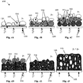
- figures 1A to 1F do not show a closed mold for reasons of clarity. Instead, the bearing surface of the particles represents a side wall 131 of a mold according to the invention, on which a first layer of a particulate starting material 110 is provided in Figure 1A .
- the method 100 further comprises the step of softening the starting material.
- the softening is represented by heating 120 of the particulate starting material 110. This process maybe performed at a constant initial pressure p 0 , wherein p 0 may be atmospheric pressure or overpressure.
- the heating 120 is achieved by means of heat input via the mold, which may be achieved by irradiating the mold wall 131, in particular by means of infrared radiation (IR radiation), or a variothermally temperature-controlled mold wall 131.
- IR radiation infrared radiation
- heating may also be achieved by direct heat input into the starting material, for example by electromagnetic radiation or IR radiation.
- a radiation emitter may be placed inside the mold.
- a preferred range of electromagnetic radiation is between 1 and 300 GHz.
- the first layer of the particulate starting material 110 begins to soften over time and adhere to the mold wall 131, which is shown schematically in Figure 1B for the first layer 110. Further particles in a second 111, third 112 and further layers begin to sinter with particles that have already been softened and plasticized. Thus, the particulate starting material melts layer by layer until the entire starting material is in a softened, especially molten liquid, state 113. This process is shown in figures 1C to 1E . It should be noted that for reasons of clarity, the individual layers in Figures 1A to 1D are added step by step. However, it is preferable to provide at least part of the particulate starting material in one step and then soften it layer by layer as shown.
- gas inclusions 114 between the individual particles are trapped by the sintering processes occurring in the melt phase that is forming.
- the trapped gas or gas mixture 114 may be air or nitrogen.
- Further gas inclusions 114 may also be created, for example, by using starting materials with particles of a porous nature.
- the particle size, shape and particle size distribution may significantly define the dimension, number and distribution of the gas inclusions 114 in the melt 113 and thus the starting condition for the foaming.
- the polymer materials used may be thermoplastic materials and/or cross-linking materials.
- the softened material must be in the viscous phase, wherein a viscosity in the region of 10 1 to 10 5 Pa ⁇ s, preferably 10 2 to 10 4 Pa ⁇ s, is advantageous for a foaming.
- the viscous melt may provide space for expanding gas inclusions due to its flowability, which is what makes expansion possible in the first place.
- the melt is tough enough in this viscosity range to bind the expanding gas inclusions 115 in the melt. The binding may at least partially prevent the expanded gas inclusions 115 from rising in the melt due to their lower density compared to the softened starting material 113.
- the binding may prevent a cell collapse or a cell wall breakthrough of the expanded gas inclusions 115 in the melt.
- the viscosity of the softened starting material may be a parameter for the formation of different cell structures, e.g., open-cell, mixed-cell, closed-cell or similar, in addition to the amount of the induced pressure change.
- the method 100 comprises the step of inducing a pressure change within the mold to cause foaming in at least a part of the softened starting material 113 without the use of an additional blowing agent besides the process atmosphere.
- the foaming is based on an expansion of the trapped gases 114 within the melt 113.
- the expansion may be caused by an induced pressure drop within the mold, wherein the applied mold pressure at the beginning of the process the pressure applied to induce foaming are represented by p 0 and p 1 .
- a preferred pressure change may lie in a range from 0.05 to 5.0 bar, wherein already a pressure change in the range from 0.2 to 1.0 bar may be sufficient for an expansion.
- the reduction of the initial pressure may be done by an external pump.
- the foaming may be considered complete when the pressure inside the gas inclusions 115, based on the expansion, has adapted to the reduced pressure p 1 within the mold.
- the foamed starting material 116 has to be solidified or stabilized together with the expanded gas inclusions 115.
- the stabilization of the expanded gas inclusions 115, which subsequently form the foam cells of the foam component, may occur by solidifying the foamed starting material 116 by means of a cooling process 123.
- a triggering of a cross-linking reaction may lead to the stabilization of the foam cells 115.
- the assembly 200 comprises a mold 230, which is rotatably mounted on a shaft 234.
- a substantially constant thickness of a foam component may be produced, wherein minor production-related differences in thickness in the order of 1-5% are encompassed by the formulation "substantially".
- the mold 230 comprises a cylindrical outer wall 231, which may be hermetically sealed with a lower flange 232 and an upper flange 233.
- the mold 230 may be suitable for producing hollow bodies, for example.
- the mold 230 is suitable for both under-as well as overpressure in a range from 1 mbar up to 50 bar, wherein a pressure difference of only a few hundred millibars after softening of the starting material may be sufficient for foam formation.
- the outer wall 231 may be heated by an IR radiator 235, whereby the starting material in the mold 230 (not shown in Figure 2 ) may be heated via the outer wall 231.
- a pyrometer 236 is located inside the mold 230, which may determine the temperature of the softened starting material and/or the melt.
- Other temperature sensors such as a thermoelement or an oscillating quartz crystal, may be used instead of or in conjunction with the pyrometer 236.
- a connector 237 is attached to the lower flange 232 via a rotary union 238. This connector 237 may be connected to a vacuum pump for pressure reduction as well as to a compressor or a device using compressed gas to generate overpressure.
- the mold 230 may be divided into individual segments (not shown in Figure 2 ) in which the internal pressure may be individually adjusted. Individual regions of the mold may also be heated or cooled separately. By a subdivision of the mold, a graded or sectionally different foam component may be produced.
- Figure 3 shows an exemplary profile 300 of an internal pressure as continuous line 340 and a temperature of the starting material as dotted line 341 depending on the duration of the process during the performing of an example of a method according to the invention.
- the starting material is at room temperature 320 or slightly higher, i.e., 10-15 °C, due to residual heat of the mold from previous manufacturing processes or the waste heat of the entire assembly.
- the internal pressure 325 of the filled and sealed mold is atmospheric pressure at the beginning of the method.
- the starting material is heated to melting temperature or above, and left at this temperature for a certain, preferably isothermal, holding time 322.
- the holding time 322 above the melt temperature may ensure that the entire starting material is present in a softened or melt-like state, or at least that sintering is possible by softening the surface of the particles.
- a number of dissolved gas inclusions in the melt may be reduced.
- heat is introduced into the material via the mold, this occurs first in the layer in contact with the mold wall and then spreads further into the interior of the melt.
- a foam-free outer layer and/or an integral foam structure may be achieved in the produced foam component.
- the point in time time of the pressure reduction 326 and thus the vacuum application temperature within the cooling process 323 may be made dependent on the viscosity of the melt, which increases during the cooling process 323. Due to the pressure reduction 326, the undissolved gas inclusions in the softened starting material, i.e., the melt, expand, causing the foaming. Once the internal pressure of the gas inclusions has adapted to the reduced internal pressure of the mold, the foaming is complete.
- the holding time 327, during which the underpressure is maintained, may depend on the viscosity, the absolute value of the pressure reduction and other parameters of the foaming.
- the internal pressure may be increased again 328 until atmospheric pressure 329 is reached, the mold may be opened and the at least partially finished foam component may be removed.
- further profiles are also possible within the scope of the present invention, with in particular different points in time and absolute values of at least one temperature change and at least one pressure change.
- Figure 4 shows an experimentally determined profile 400 of a density of a manufactured foam component depending on the induced pressure change.
- profile 400 At least eight foam components were produced under different induced pressure changes, their density was determined according to DIN EN ISO 845 standard, and between the resulting measuring points 401 it was interpolated 402. Since the density reduction in the present case is based on the expanded gas inclusions, this may be regarded as a measure of the foaming or the degree of foaming.
- curve 402 clearly shows that for the method used in the invention for producing a foam component, a few hundred millibars may be sufficient to cause the foaming.
- the density of a foam component according to the invention may be reduced to more than one third without the use of additional blowing agents.
- the method according to the invention is particularly suitable for lightweight construction, for producing buoyancy aids, such as for boats, swimming aids or surfboards, or other fields of application.
- FIG. 5A photographic images 500 and in Figure 5B computed tomography images 501 of foam components according to the invention with different degrees of foaming or density are schematically represented.
- high-density polyethylene PE-HD
- other starting materials in particular thermoplastic or cross-linking polymer materials
- gas inclusions 514 may occur in the solidified starting material 516 due to the particulate starting material, but these are not present in expanded form.
- edge layer 517 which was in contact with the mold wall.
- the size of the expanded gas inclusions 515 in the solidified starting material 516 increases further.
- the gas inclusions are essentially, i.e., with a few exceptions, mixed-cell.
- the edge layer 517 always comprises fewer gas inclusions than the remaining rest of the solidified starting material 516.
- the thickness of this edge layer 517 may be between 0.1 mm and 2.0 mm, but preferably between 0.5 mm and 1.5 mm.
- the density of a foam component according to the invention is at least partially adjustable by an amount of the pressure change.
- Figure 6A shows a foam component 600 according to the invention and a part 601 of a foam component according to the invention, in which no foaming has occurred, side by side for direct comparison.
- Both foam components 600, 601 consist of solidified starting material 616, wherein only in the foam component 600 expanded gas inclusions 615 are clearly visible. The gas inclusions cause a considerable increase in the volume, especially in the thickness, of the foam component 600.
- the present invention allows the production of foam components 600 with a lower density compared to the unfoamed starting material without the use of additional blowing agents.
- Figure 6B shows a schematic close-up cross-section of another foam component 610, which was made of thermoplastic polyurethane, TPU, for example.
- the foam component 610 comprises expanded gas inclusions 615 in the solidified starting material 616.
- an edge layer 617 which was in contact with the mold wall during production, for example, is free of gas inclusions. In this way, the method according to the invention may be used particularly efficiently for producing integral foam structures without the use of blowing agents.
- FIG. 6C schematically shows another foam component 620 according to the invention. Similar to foam component 610, foam component 620 also comprises a gas inclusion-free edge layer 617 and expanded gas inclusions 615 in the solidified starting material 616. In this case, however, a further edge layer 618, which also comprises no gas inclusions, was applied to the foam component 620.
- the second edge layer 618 may also consist of the solidified starting material 616 or a different material.
- a possible production method for foam component 620 may comprise the following steps: providing a particulate starting material in a mold; closing the mold and inducing a vacuum in the mold; softening a first portion of the starting material, in particular the portion corresponding to the edge layer 617; providing atmospheric pressure in the mold; softening a second portion of the starting material, in particular the portion in which gas inclusions are intended, the softening of the second portion being performed at atmospheric pressure; inducing an underpressure to cause a foaming in the second portion; softening a third portion at underpressure, in particular the portion corresponding to the edge layer 618; solidifying the foamed and non-foamed starting material, providing atmospheric pressure after the solidifying and subsequently opening the mold.
- the foaming may be individually adjusted in each of these regions by means of a temperature and pressure profile in at least two regions within the mold.
- the present invention is particularly suitable for providing individual layers with different degrees of foaming and thus properties of a foam component within one production process, wherein a subsequent gluing of the individual layers may be dispensed with.
- the method according to the invention is not limited to three layers. More than three layers and/or a use of different materials in the individual layers may also be provided for by a method of the present invention.
- FIG. 6D schematically shows another foam component 630 according to the invention. Similar to the foam components 610, 620, the foam component 630 also comprises a gas inclusion-free edge layer 617 and expanded gas inclusions 615 in the solidified starting material 616. In this case, however, a further edge layer 619, which also comprises gas inclusions, was applied to the foam component 630.
- the edge layer 619 consists of a different starting material than the solidified starting material 616, but may also consist of the same material.
- the second material may comprise a filler, such as fibers, or a reinforcing element in which the foaming is not caused. The second material may be at least partially surrounded or enclosed by the solidified material.
- FIG. 6E schematically illustrates another foam component 630 according to the invention. Similar to the foam components 610, 620, 630, the foam component 640 also comprises expanded gas inclusions 615 in the solidified starting material 616. In this case, the edge layer 617 is much thinner than in the previous embodiments 610, 620, 630, similar to foam component 600. A further difference is the graded increase in thickness of foam component 640, from a smallest thickness 652 to a largest thickness 651.
- An essentially trapezoidal structure of the foam component 640 may, for example, be deliberately adjusted by means of a mold wall that is not perpendicular to gravity, on which the particulate starting material is provided, softened and, after a reduction in pressure, solidified again.
- the essentially trapezoidal structure of foam component 640 may be caused by an induced pressure change at a graded temperature profile along the mold.
- the graded temperature profile along the mold may lead to a graded viscosity of the softened starting material, which may affect the degree of foaming or the size of the expanded gas inclusions, for example.
- other shapes of foam components may be adjusted by the orientation and shape of the mold.
- a trapezoidal shape of the foam component, similar to foam component 640 may also be achieved by graded foaming. This may be achieved, for example, by holding times at graded temperatures within the mold, which allows the number or density of gas inclusions to be adjusted.
- a graded pressure difference may be induced along the softened starting material. In these cases, however, a degree of foaming, density, cell size or other parameters of the foam produced would also be graded along the solidified starting material (not shown in Figure 6E ).
- Possible foam components that are free of additional blowing agents and may be obtained by the method according to the invention are, for example, insulating materials. Due to the expanded gas inclusions and a usually poor conductivity of these gases, especially a poor thermal conductivity, they may be advantageously used for insulation, especially for thermal insulation.
- foam components which are free of additional blowing agents and may be produced by the method according to the invention are, for example, damping materials, especially for sports articles.
- An advantage of producing shoes by means of the described method is, for example, that the production is possible completely without lasts. Shoe production without lasts according to the method according to the invention is more flexible and saves time and costs.
- the method according to the invention is advantageous for producing multilayer elements, such as those required for shoe soles or protectors, in a single production process, since subsequent bonding of the different layers or elements maybe dispensed with.
- the produced sports articles, in particular sportswear are better suited for direct contact with the skin than comparable state-of-the-art sports articles due to the absence of additional blowing agents.
- sports articles such as balls, protectors, helmets, shin guards, bags, back-packs, rackets, etc. may be partially or completely manufactured by means of the method according to the invention.
- protectors depending on the part of the body to be protected, they may be obtained, for example, by means of a substantially cylindrical shape of the mold adapted to the part of the body to be protected.
- the resulting foam component may be cut in half to enable putting on a breastplate, for example.
- the protectors may also be adapted for attachment to sportswear.
- buoyancy aids such as floats, boats, swimming aids, surfboards or others may also be produced using the method according to the invention. Due to the adjustable foaming, a density, and thus a buoyancy, maybe adjusted directly during production. This may eliminate the need for complex methods of combining and connecting several different buoyancy bodies.
Landscapes
- Chemical & Material Sciences (AREA)
- Engineering & Computer Science (AREA)
- Materials Engineering (AREA)
- Health & Medical Sciences (AREA)
- Chemical Kinetics & Catalysis (AREA)
- Medicinal Chemistry (AREA)
- Polymers & Plastics (AREA)
- Organic Chemistry (AREA)
- Mechanical Engineering (AREA)
- Manufacture Of Porous Articles, And Recovery And Treatment Of Waste Products (AREA)
- Molding Of Porous Articles (AREA)
Abstract
Description
- The present invention relates to a method for producing a foam component, a mold for performing the method and a foam component produced in such a way.
- The production of foam components using blowing agents is a well-known process. Foaming of polymers with blowing agents may take place, for example, in a physical or chemical way. In addition, low-viscosity polymers may also be processed to foam structures mechanically, e.g., by spraying. In known physical foaming processes and methods, the blowing agent is dosed into a melt under high pressure and is thus dissolved therein. Typical blowing agents are hydrocarbons, especially butanes and pentanes, as well as the inert gases carbon dioxide and nitrogen. In known chemical processes, chemical substances are introduced into the melt, which form gaseous products in a chemical reaction under the influence of heat. Typical chemical blowing agents are isocyanate, azodicarbonamide, hydrazine, zinc carbonate or sodium bicarbonate. Common processes in which the physical or chemical foaming process is used are injection molding, extrusion or autoclave processes. Here the cell formation or nucleation of the dissolved gas takes place by a pressure drop, as for example when the melt leaves the nozzle in the case of foam extrusion. The cell growth and the resulting foam cells are mainly determined by the occurring pressure drop, the blowing agent content and the blowing agent distribution in the material. A stabilization of the cells occurs by cooling and solidifying of the plastic.
- For example,
WO 2015/182721 A1 refers to the production of a foam-molded article. -
CN 105 451 956 B refers to a method for producing a low-density foamed article. -
EP 2 139 658 B1 refers to a method for producing foamed plastic parts with a solid outer skin and a foamed core. - Furthermore, Vetter et al. in "Influence of vacuum on the morphology and mechanical properties in rotational molding" published in the International Journal of Polymer Science refer to the fact that rotational molding is suitable for the production of seamless hollow bodies with a high degree of design flexibility.
- Further prior art is known from
DE 10 2015 000 393 A1 ,GB 1 060 908 A DE 17 29 011 A ,DE 10 2016 223 980 A1 andDE 10 2018 008 534 A1 . - It has been found to be a disadvantage of known foaming processes that a large proportion of the known blowing agents may have a negative impact on the environment. In addition, there is a risk that some of the blowing agent may remain in the produced foam component, which, in addition to the above-mentioned environmental pollution, may also have a negative effect on the health of living creatures near these foam components, e.g., components of a sports article, insulating materials in vehicles, etc. Furthermore, the use of blowing agents in the production of foam components causes additional costs, which reduces the efficiency of these processes.
- The problem of the present invention is therefore to provide a method for producing a foam component which overcomes or at least mitigates the disadvantages of the state of the art. In particular, the method according to the invention shall enable an efficient production of foam components, which does not require the extra addition of blowing agents.
- This problem is solved by a method according to claim 1. The dependent claims comprise advantageous further embodiments.
- The method for producing a foam component according to the invention comprises the steps of: (a.) providing a particulate starting material in a mold; (b.) softening the starting material; (c.) inducing a pressure change within the mold to cause foaming in at least a portion of the softened starting material without the use of a blowing agent; and (d.) solidifying the foamed starting material.
- The inventors recognized that by inducing a change in pressure within the mold, it is possible to cause foaming in at least a portion of the softened starting material. Thereby, the softening of the starting material may initially lead to a local sintering of the particles. The foaming according to the invention does not require the use of an additional blowing agent besides the process atmosphere. In the context of this invention, additional blowing agents refer to conventional blowing agents, which are already known from chemical or physical foaming processes in the state of the art, for example. The foaming according to the invention may thus be categorized as a physical foaming without additional blowing agent. Thus, the present invention not only represents an efficient and more cost-effective way of producing a foam component compared to conventional methods based on additional blowing agents. By eliminating the need for an additional blowing agent, the environmental balance is also improved, which enables a more sustainable production of foam components.
- In some embodiments, the starting material may comprise particles of a size of 0.01 to 3 mm, preferably from 0.02 to 1.5 mm, particularly preferably from 0.05 to 0.7 mm. The inventors have found that the choice of particle size has a decisive effect on the quality of the foam component produced from it, wherein the specified range of particle size has proven to be particularly advantageous. In particular, the particle size may be used to specifically influence the final cell size in the foam component produced. Furthermore, the particle size may influence the cell distribution, which maybe adjusted according to the use of the foam component.
- The starting material used in this invention may be a thermoplastic and/or cross-linking polymer material. Cross-linking polymer materials may comprise thermoset materials. In this way, the present invention represents a method for a variety of different starting materials.
- In some embodiments of the present invention, the softened starting material may comprise a viscosity in the range of 101 to 105 Pa·s, preferably 102 to 104 Pa·s. The inventors have recognized that the specified viscosity of the softened starting material is particularly advantageous for causing the foaming. For example, sufficient flowability and/or deformability of the starting material is a prerequisite for the expansion of inclusions in the starting material upon an induced pressure drop. If the viscosity of the softened starting material is too low, the gas inclusions may not be stabilized in the softened starting material before or during an expansion process. In this case the gas inclusions may diffuse to the surface. On the other hand, if the viscosity is too high, a considerable pressure difference maybe necessary to cause an expansion process at all. The choice of the viscosity of the softened starting material may also influence the type of gas inclusions, especially a thickness of the cell walls of the expanded gas inclusions.
- In some embodiments of the present invention, the softening in step (b.) may comprise an inclusion of at least one gas, in particular air or nitrogen, in the softened starting material. The inventors have found that during the softening of the starting material, viscous particle edge layers may form, which is generally referred to as "sintering". In the course of these sintering processes, the process gas or process gas mixture, in particular air or nitrogen, present between the particulate starting material is enclosed in the softened starting material. Alternatively or additionally, such gas inclusions may be caused by starting materials with particles of porous nature. In this case, the at least one gas may not only be present between the individual particles, but may already be present within the porous particulate starting material. In both cases, chemical blowing agents or additional gases maybe dispensed with in the mold, thus helping to protect the environment. In addition, the use of gases or gas mixtures already present in the mold, such as air, may reduce the costs of the method. Furthermore, it is possible to use a protective gas, such as nitrogen, as process gas to avoid thermo-oxidative degradation processes in the softened starting material. Similar to the use of air as a process gas mixture, this would also be environmentally friendly and/or cost-effective. Furthermore, the use of a protective gas may be gentler on the material than air.
- In addition, the foaming may be caused by expansion of at least one gas trapped in the softened starting material. In this way, the present invention represents a particularly advantageous method of generating gas inclusions in a softened material and causing them to expand and thus to foam by changing the pressure within the mold.
- In some embodiments of the present invention, the softening of step (b.) may comprise heating of the starting material. Softening the starting material by heating represents a method step which may be controlled very precisely with current control technology. This is an important factor for the production of a high-quality foam component according to the present invention. For example, by heating, it is possible to adjust a viscosity of the softened material very precisely, which in turn may influence the foam formation.
- Furthermore, the heating of the starting material may comprise heating by direct heat input into the starting material or heat input via the mold. Additionally or alternatively, the heating may be done by heat conduction or convection.
- In case of a direct heat input into the starting material, it may be realized by electromagnetic radiation, especially in the range of 1 to 300 GHz. In addition, thermal radiation, especially in the infrared range, may be used. In both cases it is possible to direct the radiation directly into the mold or to place the radiation emitter inside the mold. In this way, the present invention enables heating of the starting material inside the mold without having to heat the mold itself. Thus, the energy and cost efficiency of the present method may be improved compared to conventional state-of-the-art processes.
- In case of a heat input into the starting material via the mold, a declining temperature gradient from the mold wall to the inside of the mold may be present in the softened starting material. In this way, for example, the particulate starting material in contact with the inner wall of the mold is softened first. This may cause the layer of the starting material that was softened first to adhere to the wall of the mold. Particles further inside may consequently sinter through contact with the already plasticized particles. Thus, the particulate starting material may melt layer by layer until the entire material is in a molten state. This leads to an advantageous gas inclusion in the softened starting material according to the present invention.
- In some embodiments of the present invention, a number of gas inclusions in the softened starting material may be adjustable via a temperature profile of the heating. The inventors have found out that, with extensive heat supply, depending on the solubility of the gas or gas mixture present, such as air or nitrogen, diffusion of the gas molecules in the softened starting material, especially into the polymer melt, may occur. Thereby, the number of gas inclusions in different layers or regions may be selectively adjusted according to the temperature profile of the region of the softened starting material. For example, it is possible to reduce the number of gas inclusions by heat supply.
- In particular, an edge layer of the starting material which is in contact with the mold may comprise fewer gas inclusions than other regions of the starting material. If the heat input is caused via the mold, a heating of the starting material from outside to inside occurs. In this way gas inclusions in the regions of the softened material in contact with the mold wall may be reduced or dissolved first. This makes it possible, for example, to produce integral foam structures with an adjustable edge layer thickness by means of targeted temperature control. The term "integral foam structure" is to be understood in relation to the present invention as foam structures which comprise a core of foam cells and an essentially cell-free edge. The term "essentially cell-free edge" encompasses fluctuations and inaccuracies typical for production.
- In this case, the edge layer may comprise a thickness of 0.1 to 2.0 mm, preferably of 0.3 to 1.7 mm, particularly preferably of 0.5 to 1.5 mm. In this way, the present invention represents a method for producing integral foam structures comprising a preferred thickness of the edge layer of a few micrometers. Hereby a particularly high bending strength of the foam component may be achieved. Furthermore, a low density of the foam component may be achieved. A low density, for example, has a positive effect on the weight of the foam component. In addition, material costs for producing the foam component may be reduced.
- In some embodiments of the present invention a processing temperature of the starting material may be above its melting temperature. In this way, for example, a density of gas inclusions in the softened material may be controlled. Thus, a structure of the foam component, in particular a foam density or a foam degree, may be advantageously adapted to the respective use.
- In some embodiments of the present invention, a temperature inside the mold may be different in at least two regions of the mold. Furthermore, the choice of the temperature at which the pressure change is brought about may influence the properties of the foam component, such as density, cell size, cell distribution, etc. In this way, at inhomogeneous thermal conditions, which may be specifically adjusted by local temperature control of different regions within the mold, for example, a local foaming or a locally different foaming may be caused. It is also possible to generate graded properties via a locally varying temperature profile within the mold.
- In some embodiments of the present invention, the pressure change may comprise a reduction of the pressure. The inventors have found that by reducing the pressure within the mold, any gas inclusions within the softened starting material that may be present or may be deliberately caused will adapt to the pressure reduction, especially by expansion. Thus, pressure reduction may be used advantageously to provide for foaming. A prerequisite for expansion of the gas inclusions due to the induced pressure reduction is sufficient flowability or deformability of the softened starting material surrounding the expanding gas inclusions. In case that a gas expansion is possible due to the external factors, the foaming may take place at least until the pressure present in the gas inclusions corresponds to the pressure set by the pressure reduction in the mold. In this way, the pressure reduction may comprise a parameter for adjusting the size increase of the gas inclusions, in particular a foam bubble size resulting therefrom.
- In some embodiments of the present invention, the pressure change may amount to 0.05 to 5.0 bar, preferably 0.1 to 2.0 bar, particularly preferably 0.2 to 1.0 bar. The inventors have recognized that for a method for producing a foam component according to the invention, in contrast to proven methods from the state of the art, already a few hundred millibar may be sufficient. Hence, molds that may be produced more cheaply are suitable for the method according to the invention and may only be adapted for small pressure differences. This may lead to a considerable cost reduction of the claimed method. Especially in the production of large foam components, such as tanks, housings for devices and equipment, etc., which are usually produced by rotational molding, considerable cost savings may be achieved in mold production due to the low pressure differences required. In addition, lower pressure differences within the mold are achieved more quickly compared to proven methods. Thereby, the duration of the production process of individual foam components may be shortened, making the method according to the invention more efficient than proven, longer lasting methods. In addition, the method according to the invention may offer the possibility to make physical foaming according to the invention accessible also for methods in which physical foaming is largely excluded, since a more cost-intensive molding technique for adapting the molds used to high pressures would be necessary.
- In some embodiments of the present invention, an initial pressure in the mold before the softening may correspond to atmospheric pressure or overpressure. The inventors have found that one of the parameters for causing the foaming in the softened starting material is the absolute value of the pressure change after softening of the starting material. Thus, an initial pressure at one atmosphere may cause the foaming by creating negative pressure in the mold. On the other hand, it is possible to use an initial pressure above one atmosphere, i.e., with overpressure in the mold, to cause the foaming by reducing the overpressure, especially up to atmospheric pressure. In this way, the method according to the invention represents a flexible method with respect to the internal pressure of the mold. This may, for example, play an important role with respect to the mold to be used, in particular its suitability for overpressure or underpressure, respectively, to further manufacturing steps after the inducing the pressure change, in particular during or after solidifying the foamed starting material, and/or to other parameters.
- Furthermore, the inventors have found that by generating an overpressure at a point in time when only a part of the starting material, in particular an outermost layer or region, is in a softened state, gas inclusions in this softened part may be reduced. In parts, layers or regions which are softened only after overpressure has been generated, gas inclusions may still occur. By reducing the pressure at a later time, these gas inclusions, which remain in the softened parts after the overpressure has been generated, may be expanded. By controlling the points in time at which overpressure or underpressure is applied in the mold, a layer thickness, a degree of foaming, a material density or other parameters of the foam component, of the individual layers or of the entire foam component may be specifically adjusted.
- Furthermore, the overpressure may comprise compressed air. In this way, cost-intensive and/or environmentally harmful use of additional gases may be avoided in the production of foam components according to the invention. Alternatively, the overpressure may comprise compressed nitrogen. Compared to air, this provides an equally cost-effective and/or environmentally friendly method for producing foam components. Furthermore, thermo-oxidative degradation processes in the softened starting material may be avoided by the use of nitrogen.
- In some embodiments of the present invention, the inducing of the pressure change may comprise inducing the pressure change upon reaching or above the melting temperature of at least a portion of the starting material. The inventors have recognized that a viscosity of the starting material changes depending on the temperature. Furthermore, they have found that the foaming according to the invention develops differently depending on the viscosity of the softened material with respect to the already mentioned parameters of the foam, such as density, cell size, number of cells, etc. Thus, the possibility of inducing the pressure change at different temperatures in relation to the melting temperature of the starting material represents a possibility for adjusting the parameters of the foam component.
- In some embodiments of the present invention, an absolute value of the pressure change within the mold may be different in at least two regions of the mold. Since the absolute value of the pressure change represents an essential parameter for the size of individual cells in the foamed starting material, a varying cell size in the foam component may be adjusted by at least two different pressure change ranges.
- In some embodiments of the present invention, the foaming in each of these regions may be individually adjustable by a temperature and/or pressure difference in at least two regions within the mold. Thus, the method according to the invention offers the possibility to individually adjust individual regions of the foam component to the intended use. For example, in regions with an increased need for stability, a cell size within the foam component may be deliberately kept small. Furthermore, the cell size may be increased and/or a density of the starting material may be reduced in another part where low weight is advantageous.
- In some embodiments of the present invention, the foaming may not be caused in at least one region of the mold. In this way, the present invention provides a possibility to provide foamed and non-foamed regions in a foam component within a production process. An additional joining of foamed and non-foamed regions may thus be dispensed with.
- In some embodiments of the present invention, the solidifying may comprise solidifying after the inducing the pressure change. The inventors have recognized that a stabilization or solidification of the resulting foam structure takes place as soon as the flowability or deformability due to a selected pressure change does not allow further expansion of the gas inclusions. It is therefore advantageous to wait until after the induced pressure change, especially after the foaming has been initiated, before solidifying. In the case of cross-linking starting materials, e.g., thermoset starting materials, a cross-linking reaction may lead to a solidification or stabilization of the foam structure.
- In some embodiments of the present invention, the solidifying may comprise cooling of the foamed starting material. In the case of thermoplastic starting materials, for example, the solidifying may be achieved by solidifying the softened starting material during a cooling process. Thus, a cooling of the foamed starting material, especially by cooling the mold, may be an advantageous and well controllable process for solidifying.
- In some embodiments of the present invention, a density of the foam component may be at least partially adjustable by an amount of the pressure change. The inventors have recognized that the increase in size of individual gas inclusions in the softened starting material maybe adjusted by an amount of the pressure change. Since the increase of the size of the gas inclusions of the foam material component means a reducing of its density, the density of the foam component may thus be adjusted by the amount of the pressure change in efficient way.
- In some embodiments of the present invention, a structure of the foam component may be influenced at least partially by at least one of the following properties of the starting material: material of the particles, particle shape, particle size and particle size distribution.
- The inventors have found that the method according to the invention for producing foam components offers, in addition to the control of the density by means of pressure, further possibilities on the process side to influence the properties of the resulting foam components. For example, the choice of the starting material represents a central control variable. Furthermore, the initial diameter of the starting material in the softened state and before expansion of existing gas inclusions is decisive for the final cell size and distribution in the foamed starting material. Thus, the particle shape, particle size and particle size distribution may have a positive influence on the resulting foam structure. In the same way, the foam structure may be set or adjusted differently locally or in parts of the foam component by the use of different particle sizes, which may be arranged in the mold in a separated way from each other, for example side by side. The varying bubble diameters of the resulting gas inclusions may thus lead to different degrees of foaming in the corresponding regions or parts after foaming with a uniform pressure drop in the mold. A multimaterial application or the use of polymer blends is also possible according to the invention and represents a further parameter for influencing or adapting the foam component. For example, the particles of the starting material may comprise a so-called "core-sheath structure", whereby a particle core and a particle sheath may comprise different properties such as softening or solidification behavior or similar. In this way, among other things, the processing and/or application properties of a foam component according to the invention may be deliberately optimized. It is also possible to coat a thermoplastic particle core in a thermoset or elastomeric manner. In this way, for example, an improved compressive deformation behavior of the softened starting material may be achieved. Likewise, elastomeric particle cores, for example recycled material, e.g., from old car tires or used sports articles, may be coated with a thermoplastic particle coating for producing foam components according to the invention.
- In some embodiments of the present invention, the method may further comprise introducing a second material into the mold. In this way, the method provides a production of a foam component which may be adapted to a variety of uses.
- In some embodiments of the present invention, the second material may comprise a filler or a reinforcing element. Thus, for example, besides an advantageous low density of the foam component, a particularly high stability of the foam component may be achieved. Likewise, a variety of properties of other materials, in particular of fillers or reinforcing elements, may be integrated into the foam component by means of the method according to the invention.
- In some embodiments of the present invention, no foaming may occur in the second material. In this way, the basic properties of the second material may be retained despite a foaming in at least part of the starting material. Furthermore, a combination of the properties of both materials is possible.
- In another aspect, the present invention relates to a foam component produced by a method according to one of the previous embodiments.
- The numerous advantages of the present invention, which have already been explained above in relation to examples of a method for producing a foam component, are equally applicable to examples of a foam component and a mold for producing a foam component.
- In some embodiments of the present invention, the foam component may comprise a hollow body. In this way, the method according to the invention, especially by rotational molding, represents an efficient possibility to produce high-quality hollow bodies from foamed material without using chemical blowing agents.
- In some embodiments of the present invention, the foam component may comprise a non-foamed edge layer.
- In some embodiments of the present invention, the edge layer may comprise a thickness of 0.1 to 2.0 mm, preferably of 0.3 to 1.7 mm, particularly preferably of 0.5 to 1.5 mm.
- In some embodiments of the present invention, the foam component may be free of blowing agents.
- In some embodiments of the present invention, the foam component may comprise open-cell, mixed-cell or closed-cell gas inclusions. In this way, different properties, such as absorption of liquids in the case of open-cell gas inclusions or, in contrast, repellence of liquids in the case of closed-cell gas inclusions, may be set in the foam component produced. In the case of closed-cell gas inclusions, a foam component according to the present invention is, due to its adjustable density, advantageously suited as buoyancy aid in floating bodies, in particular boats, swimming aids or surfboards.
- In some embodiments of the present invention, the foam component may comprise an integral foam structure.
- In some embodiments of the present invention, the foam component may be formed as an insulating material. Since an expansion of the gas inclusions is adjustable in foam components according to the invention, and since air and a plurality of polymer materials provide poor heat conduction properties, the foam components according to the invention maybe particularly well suited as insulating material.
- In some embodiments of the present invention, the foam component may comprise a damping material, in particular for sports articles. As already mentioned above, the method according to the invention may be used to adjust the number and size of gas inclusions in a foam component. Furthermore, this method may be used to produce foam components from starting materials with rubber-elastic properties, such as thermoplastic elastomers. In this way, damping materials with excellent mechanical damping properties and comfort features, such as those advantageous for shoe soles, may be produced particularly efficiently. In particular, different elements of a shoe sole, including outsole, midsole or the like, for which it is advantageous to have different properties, such as thermal insulation, damping, cushioning, etc., maybe produced in one process step according to the invention. This may eliminate the need for time- and cost-intensive joining or gluing of the individual elements.
- In some embodiments of the present invention, the foam component may comprise a part of a sports article, in particular a ball or protector. A part of a ball may, for example, comprise one layer of a panel or a plurality of different layers of a panel. The different layers may comprise, among others, an outer top layer, a middle foam layer and a base layer, each of which comprises different properties. The plurality of different layers may be produced separately and subsequently joined together. Alternatively, the plurality of different layers, in particular including an inner bladder of the ball, may be advantageously produced in one process. In this way, the present invention provides a particularly sustainable method for producing balls, in which gluing of the individual panel layers may be dispensed with. In addition, producing individual layers in one process step considerably reduces the amount of residual material compared to conventional methods, which are already known from the state of the art. It should be noted that the production of a plurality of different layers in a method according to the invention is not limited to the production of balls but is suitable for a plurality of foam components. If the part of a sports article relates to a protector, these may comprise helmets, shin guards, breastplates, joint protectors, etc. Such protectors maybe adapted for attachment to sportswear. Furthermore, the component part of a sports article may comprise at least part of a backpack, bag, stick, in particular a field hockey stick, or similar.
- In another aspect, the present invention relates to a mold adapted for performing a method for producing a foam component according to the present invention and comprising a control device, in particular for reducing the pressure in the mold.
- In some embodiments of the present invention, the mold may be adapted for a maximum pressure up to 50 bar, preferably 25 bar, particularly preferably 10 bar, and most preferably atmospheric pressure.
- In some embodiments of the present invention, the mold may be adapted for a minimum pressure up to 0.8 bar, preferably 0.5 bar, more preferably 0.2 bar, particularly preferably 0.1 bar.
- In some embodiments of the present invention, the pressure and/or a temperature may be individually adjustable in at least two regions within the mold.
- In some embodiments of the present invention, the mold may be adapted to be movable. In this way, the mold according to the invention is suitable for a variety of molding processes, in particular for rotational molding or movement molding.
- In the following, aspects of the present invention will be explained in more detail with reference to the accompanying figures. These figures show:
- Fig. 1A to 1F:
- A schematic illustration of the method according to the invention;
- Fig. 2:
- A schematic illustration of a mold for producing a foam component according to the invention;
- Fig. 3:
- Exemplary profile of the pressure or the temperature, respectively, depending on the time during performing of the method according to the invention;
- Fig. 4:
- Profile of the density of a foam component according to the invention depending on an induced pressure reduction;
- Fig. 5A and 5B:
- A schematic illustration of a foam component according to the invention after inducing different pressure reductions; and
- Fig. 6A to 6E:
- A schematic illustration of different foam components according to the invention.
- In the following, exemplary embodiments of the present invention with respect to a foam component will be explained in more detail. While specific combinations of features are described in relation to the exemplary embodiments of the present invention, it is to be understood that the disclosure is not limited to such embodiments. In particular, not all features need to be present in order to realize the invention, and the embodiments may be modified by combining certain features of one embodiment with one or more features of another embodiment.
- An example of a
method 100 according to the invention for producing a foam component is described below with reference toFigures 1A to 1F . - The
method 100 comprises as a first step providing a particulate starting material, e.g., powder, pellets, microgranules or similar, in a mold. The size of the particles, which is to be understood as the longest expansion direction of a particle, may cover a range between 0.01 and 3 mm. It should be noted thatfigures 1A to 1F do not show a closed mold for reasons of clarity. Instead, the bearing surface of the particles represents aside wall 131 of a mold according to the invention, on which a first layer of aparticulate starting material 110 is provided inFigure 1A . - The
method 100 further comprises the step of softening the starting material. InFigures 1A to 1E , the softening is represented by heating 120 of theparticulate starting material 110. This process maybe performed at a constant initial pressure p0, wherein p0 may be atmospheric pressure or overpressure. Theheating 120 is achieved by means of heat input via the mold, which may be achieved by irradiating themold wall 131, in particular by means of infrared radiation (IR radiation), or a variothermally temperature-controlledmold wall 131. Alternatively, heating may also be achieved by direct heat input into the starting material, for example by electromagnetic radiation or IR radiation. In this case, a radiation emitter may be placed inside the mold. A preferred range of electromagnetic radiation is between 1 and 300 GHz. - Due to the
heating 120 of themold wall 131, the first layer of theparticulate starting material 110 begins to soften over time and adhere to themold wall 131, which is shown schematically inFigure 1B for thefirst layer 110. Further particles in a second 111, third 112 and further layers begin to sinter with particles that have already been softened and plasticized. Thus, the particulate starting material melts layer by layer until the entire starting material is in a softened, especially molten liquid,state 113. This process is shown infigures 1C to 1E . It should be noted that for reasons of clarity, the individual layers inFigures 1A to 1D are added step by step. However, it is preferable to provide at least part of the particulate starting material in one step and then soften it layer by layer as shown. - During the melting,
gas inclusions 114 between the individual particles are trapped by the sintering processes occurring in the melt phase that is forming. The trapped gas orgas mixture 114 may be air or nitrogen.Further gas inclusions 114 may also be created, for example, by using starting materials with particles of a porous nature. The particle size, shape and particle size distribution may significantly define the dimension, number and distribution of thegas inclusions 114 in themelt 113 and thus the starting condition for the foaming. The polymer materials used may be thermoplastic materials and/or cross-linking materials. A further prerequisite for the foaming is that the softened material must be in the viscous phase, wherein a viscosity in the region of 101 to 105 Pa·s, preferably 102 to 104 Pa·s, is advantageous for a foaming. In this range, the viscous melt may provide space for expanding gas inclusions due to its flowability, which is what makes expansion possible in the first place. On the other hand, the melt is tough enough in this viscosity range to bind the expandinggas inclusions 115 in the melt. The binding may at least partially prevent the expandedgas inclusions 115 from rising in the melt due to their lower density compared to thesoftened starting material 113. On the other hand, the binding may prevent a cell collapse or a cell wall breakthrough of the expandedgas inclusions 115 in the melt. In this way, the viscosity of the softened starting material may be a parameter for the formation of different cell structures, e.g., open-cell, mixed-cell, closed-cell or similar, in addition to the amount of the induced pressure change. - In a further step, the
method 100 comprises the step of inducing a pressure change within the mold to cause foaming in at least a part of the softenedstarting material 113 without the use of an additional blowing agent besides the process atmosphere. The foaming is based on an expansion of the trappedgases 114 within themelt 113. The expansion may be caused by an induced pressure drop within the mold, wherein the applied mold pressure at the beginning of the process the pressure applied to induce foaming are represented by p0 and p1. A preferred pressure change may lie in a range from 0.05 to 5.0 bar, wherein already a pressure change in the range from 0.2 to 1.0 bar may be sufficient for an expansion. The reduction of the initial pressure may be done by an external pump. On the other hand, it is also possible to induce a pressure reduction by increasing the hermetically sealed volume of the mold, for example by moving at least a part of amold wall 131. The foaming may be considered complete when the pressure inside thegas inclusions 115, based on the expansion, has adapted to the reduced pressure p1 within the mold. - In a final step of the
method 100, the foamedstarting material 116 has to be solidified or stabilized together with the expandedgas inclusions 115. The stabilization of the expandedgas inclusions 115, which subsequently form the foam cells of the foam component, may occur by solidifying the foamedstarting material 116 by means of acooling process 123. Alternatively, in case of cross-linking polymer materials as starting material, a triggering of a cross-linking reaction may lead to the stabilization of thefoam cells 115. - An embodiment of a
mold 230 according to the invention for producing a foam component is described in the following with reference toFigure 2 . - The
assembly 200 comprises amold 230, which is rotatably mounted on ashaft 234. By means of a uniform rotating, for example, a substantially constant thickness of a foam component may be produced, wherein minor production-related differences in thickness in the order of 1-5% are encompassed by the formulation "substantially". Themold 230 comprises a cylindricalouter wall 231, which may be hermetically sealed with alower flange 232 and anupper flange 233. Themold 230 may be suitable for producing hollow bodies, for example. Furthermore, themold 230 is suitable for both under-as well as overpressure in a range from 1 mbar up to 50 bar, wherein a pressure difference of only a few hundred millibars after softening of the starting material may be sufficient for foam formation. Theouter wall 231 may be heated by anIR radiator 235, whereby the starting material in the mold 230 (not shown inFigure 2 ) may be heated via theouter wall 231. For process control, apyrometer 236 is located inside themold 230, which may determine the temperature of the softened starting material and/or the melt. Other temperature sensors, such as a thermoelement or an oscillating quartz crystal, may be used instead of or in conjunction with thepyrometer 236. In order to be able to vary the internal pressure ofmold 230, aconnector 237 is attached to thelower flange 232 via arotary union 238. Thisconnector 237 may be connected to a vacuum pump for pressure reduction as well as to a compressor or a device using compressed gas to generate overpressure. Themold 230 may be divided into individual segments (not shown inFigure 2 ) in which the internal pressure may be individually adjusted. Individual regions of the mold may also be heated or cooled separately. By a subdivision of the mold, a graded or sectionally different foam component may be produced. -
Figure 3 shows anexemplary profile 300 of an internal pressure ascontinuous line 340 and a temperature of the starting material as dottedline 341 depending on the duration of the process during the performing of an example of a method according to the invention. At the beginning, the starting material is atroom temperature 320 or slightly higher, i.e., 10-15 °C, due to residual heat of the mold from previous manufacturing processes or the waste heat of the entire assembly. Theinternal pressure 325 of the filled and sealed mold is atmospheric pressure at the beginning of the method. By means of aconstant temperature ramp 321, the starting material is heated to melting temperature or above, and left at this temperature for a certain, preferably isothermal, holdingtime 322. The holdingtime 322 above the melt temperature may ensure that the entire starting material is present in a softened or melt-like state, or at least that sintering is possible by softening the surface of the particles. On the other hand, by keeping the melt above the melting temperature, a number of dissolved gas inclusions in the melt may be reduced. When heat is introduced into the material via the mold, this occurs first in the layer in contact with the mold wall and then spreads further into the interior of the melt. Thus, over aspecific holding time 322, for example, a foam-free outer layer and/or an integral foam structure may be achieved in the produced foam component. After the end of theisothermal holding time 322, thecooling process 323 begins. During thecooling process 323, now apressure reduction 326 takes place. The point in time time of thepressure reduction 326 and thus the vacuum application temperature within thecooling process 323 may be made dependent on the viscosity of the melt, which increases during thecooling process 323. Due to thepressure reduction 326, the undissolved gas inclusions in the softened starting material, i.e., the melt, expand, causing the foaming. Once the internal pressure of the gas inclusions has adapted to the reduced internal pressure of the mold, the foaming is complete. The holdingtime 327, during which the underpressure is maintained, may depend on the viscosity, the absolute value of the pressure reduction and other parameters of the foaming. When the foamed material has finally solidified again due to thecooling process 323 and the foam has stabilized, the internal pressure may be increased again 328 untilatmospheric pressure 329 is reached, the mold may be opened and the at least partially finished foam component may be removed. In addition to theexemplary profile 300, further profiles are also possible within the scope of the present invention, with in particular different points in time and absolute values of at least one temperature change and at least one pressure change. -
Figure 4 shows an experimentallydetermined profile 400 of a density of a manufactured foam component depending on the induced pressure change. To establish theprofile 400, at least eight foam components were produced under different induced pressure changes, their density was determined according to DIN EN ISO 845 standard, and between the resulting measuring points 401 it was interpolated 402. Since the density reduction in the present case is based on the expanded gas inclusions, this may be regarded as a measure of the foaming or the degree of foaming. Thus,curve 402 clearly shows that for the method used in the invention for producing a foam component, a few hundred millibars may be sufficient to cause the foaming. At a pressure difference of only one bar, for example, the density of a foam component according to the invention may be reduced to more than one third without the use of additional blowing agents. Thus, the method according to the invention is particularly suitable for lightweight construction, for producing buoyancy aids, such as for boats, swimming aids or surfboards, or other fields of application. - In
Figure 5A photographic images 500 and inFigure 5B computedtomography images 501 of foam components according to the invention with different degrees of foaming or density are schematically represented. When producing the foam components, high-density polyethylene, PE-HD, was used, wherein other starting materials, in particular thermoplastic or cross-linking polymer materials, may also be used within the scope of the present invention. If no pressure difference is induced in a manufacturing process according to the invention, i.e., Δpv=0,gas inclusions 514 may occur in the solidified startingmaterial 516 due to the particulate starting material, but these are not present in expanded form. There are also no expanded gas inclusions in theedge layer 517 which was in contact with the mold wall. Thus, in this case, it is a region of a foam component that was present during production in a part of a mold in which the foaming was not caused. This behavior already changes with an induced pressure reduction of Δpv=400 mbar, such that thegas inclusions 515 in the solidified startingmaterial 516 are already present in expanded from. InFigure 5B it may be easily seen that the majority of the expandedgas inclusions 515 are closed-cell. - If the induced pressure difference is increased to Δpv=950 mbar or Δpv=999 mbar, as also shown in
Figures 5A and5B , the size of the expandedgas inclusions 515 in the solidified startingmaterial 516 increases further. In the case of a pressure change of Δpv=950 mbar, the gas inclusions are essentially, i.e., with a few exceptions, mixed-cell. This changes with a further increase of the pressure difference to Δpv=999 mbar, wherein in this case thegas inclusions 515 are essentially open-cell. It is noted that theedge layer 517 always comprises fewer gas inclusions than the remaining rest of the solidified startingmaterial 516. The thickness of thisedge layer 517 may be between 0.1 mm and 2.0 mm, but preferably between 0.5 mm and 1.5 mm. - Overall, it can be shown with
Figures 5A and5B that the density of a foam component according to the invention is at least partially adjustable by an amount of the pressure change. -
Figure 6A shows afoam component 600 according to the invention and apart 601 of a foam component according to the invention, in which no foaming has occurred, side by side for direct comparison. Bothfoam components material 616, wherein only in thefoam component 600 expandedgas inclusions 615 are clearly visible. The gas inclusions cause a considerable increase in the volume, especially in the thickness, of thefoam component 600. Thus, the present invention allows the production offoam components 600 with a lower density compared to the unfoamed starting material without the use of additional blowing agents. -
Figure 6B shows a schematic close-up cross-section of anotherfoam component 610, which was made of thermoplastic polyurethane, TPU, for example. Thefoam component 610 comprises expandedgas inclusions 615 in the solidified startingmaterial 616. In addition, anedge layer 617, which was in contact with the mold wall during production, for example, is free of gas inclusions. In this way, the method according to the invention may be used particularly efficiently for producing integral foam structures without the use of blowing agents. -
Figure 6C schematically shows anotherfoam component 620 according to the invention. Similar tofoam component 610,foam component 620 also comprises a gas inclusion-free edge layer 617 and expandedgas inclusions 615 in the solidified startingmaterial 616. In this case, however, afurther edge layer 618, which also comprises no gas inclusions, was applied to thefoam component 620. Thesecond edge layer 618 may also consist of the solidified startingmaterial 616 or a different material. A possible production method forfoam component 620, in case it was produced from a starting material, may comprise the following steps: providing a particulate starting material in a mold; closing the mold and inducing a vacuum in the mold; softening a first portion of the starting material, in particular the portion corresponding to theedge layer 617; providing atmospheric pressure in the mold; softening a second portion of the starting material, in particular the portion in which gas inclusions are intended, the softening of the second portion being performed at atmospheric pressure; inducing an underpressure to cause a foaming in the second portion; softening a third portion at underpressure, in particular the portion corresponding to theedge layer 618; solidifying the foamed and non-foamed starting material, providing atmospheric pressure after the solidifying and subsequently opening the mold. In this way, the foaming may be individually adjusted in each of these regions by means of a temperature and pressure profile in at least two regions within the mold. Thus, the present invention is particularly suitable for providing individual layers with different degrees of foaming and thus properties of a foam component within one production process, wherein a subsequent gluing of the individual layers may be dispensed with. It should be noted that the method according to the invention is not limited to three layers. More than three layers and/or a use of different materials in the individual layers may also be provided for by a method of the present invention. -
Figure 6D schematically shows anotherfoam component 630 according to the invention. Similar to thefoam components foam component 630 also comprises a gas inclusion-free edge layer 617 and expandedgas inclusions 615 in the solidified startingmaterial 616. In this case, however, afurther edge layer 619, which also comprises gas inclusions, was applied to thefoam component 630. Theedge layer 619 consists of a different starting material than the solidified startingmaterial 616, but may also consist of the same material. Likewise, the second material may comprise a filler, such as fibers, or a reinforcing element in which the foaming is not caused. The second material may be at least partially surrounded or enclosed by the solidified material. -
Figure 6E schematically illustrates anotherfoam component 630 according to the invention. Similar to thefoam components foam component 640 also comprises expandedgas inclusions 615 in the solidified startingmaterial 616. In this case, theedge layer 617 is much thinner than in theprevious embodiments foam component 600. A further difference is the graded increase in thickness offoam component 640, from asmallest thickness 652 to alargest thickness 651. An essentially trapezoidal structure of thefoam component 640 may, for example, be deliberately adjusted by means of a mold wall that is not perpendicular to gravity, on which the particulate starting material is provided, softened and, after a reduction in pressure, solidified again. Likewise, the essentially trapezoidal structure offoam component 640 may be caused by an induced pressure change at a graded temperature profile along the mold. The graded temperature profile along the mold may lead to a graded viscosity of the softened starting material, which may affect the degree of foaming or the size of the expanded gas inclusions, for example. To the same extent, other shapes of foam components may be adjusted by the orientation and shape of the mold. On the other hand, a trapezoidal shape of the foam component, similar tofoam component 640, may also be achieved by graded foaming. This may be achieved, for example, by holding times at graded temperatures within the mold, which allows the number or density of gas inclusions to be adjusted. Alternatively, a graded pressure difference may be induced along the softened starting material. In these cases, however, a degree of foaming, density, cell size or other parameters of the foam produced would also be graded along the solidified starting material (not shown inFigure 6E ). - Possible foam components that are free of additional blowing agents and may be obtained by the method according to the invention are, for example, insulating materials. Due to the expanded gas inclusions and a usually poor conductivity of these gases, especially a poor thermal conductivity, they may be advantageously used for insulation, especially for thermal insulation.
- Other foam components which are free of additional blowing agents and may be produced by the method according to the invention are, for example, damping materials, especially for sports articles. An advantage of producing shoes by means of the described method is, for example, that the production is possible completely without lasts. Shoe production without lasts according to the method according to the invention is more flexible and saves time and costs. Furthermore, the method according to the invention is advantageous for producing multilayer elements, such as those required for shoe soles or protectors, in a single production process, since subsequent bonding of the different layers or elements maybe dispensed with. In addition, the produced sports articles, in particular sportswear, are better suited for direct contact with the skin than comparable state-of-the-art sports articles due to the absence of additional blowing agents.
- In addition, sports articles such as balls, protectors, helmets, shin guards, bags, back-packs, rackets, etc. may be partially or completely manufactured by means of the method according to the invention. In the case of protectors, depending on the part of the body to be protected, they may be obtained, for example, by means of a substantially cylindrical shape of the mold adapted to the part of the body to be protected. In an optional post-processing step, the resulting foam component may be cut in half to enable putting on a breastplate, for example. The protectors may also be adapted for attachment to sportswear.
- Finally, buoyancy aids, such as floats, boats, swimming aids, surfboards or others may also be produced using the method according to the invention. Due to the adjustable foaming, a density, and thus a buoyancy, maybe adjusted directly during production. This may eliminate the need for complex methods of combining and connecting several different buoyancy bodies.
- In the following, further examples are described to facilitate the understanding of the invention:
- 1. A method for producing a foam component, comprising the steps of:
- a. providing a particulate starting material (110, 111, 112) in a mold (230);
- b. softening the starting material (110, 111, 112);
- c. inducing a pressure change within the mold to cause foaming in at least a portion of the softened starting material (113) without the use of a blowing agent; and
- d. solidifying the foamed starting material (116).
- 2. Method according to example 1, wherein the starting material (110, 111, 112) comprises particles of a size of 0.01 to 3 mm, preferably of 0.02 to 1.5 mm, particularly preferably of 0.05 to 0.7 mm.
- 3. Method according to example 1 or 2, wherein the starting material (110, 111, 112) comprises a thermoplastic and/or crosslinking polymer material.
- 4. Method according to one of examples 1-3, wherein the softened starting material (113) comprises a viscosity in the range of 101 to 105 Pa·s, preferably 102 to 104 Pa·s.
- 5. Method according to any of the examples 1-4, wherein the softening comprises an inclusion of at least one gas (114), in particular air or nitrogen, in the softened starting material (113).
- 6. Method according to example 5, wherein the foaming is caused by expansion of the at least one gas (114) trapped in the softened starting material (113).
- 7. Method according to any of the examples 1-6, wherein the softening comprises heating (120) the starting material (110, 111, 112).
- 8. Method according to example 7, wherein the heating (120) of the starting material (110, 111, 112) comprises heating (120) by direct heat input into the starting material (110, 111, 112) or heat input via the mold (230).
- 9. Method according to any of the examples 7-8, wherein a number of gas inclusions (114) in the softened starting material (113) is adjustable via a temperature profile of the heating.
- 10. Method according to example 9, wherein an edge layer (517, 617) of the starting material which is in contact with the mold (230) comprises fewer gas inclusions (114) than other regions of the starting material (113).
- 11. Method according to example 10, wherein the edge layer (517, 617) comprises a thickness of 0.1 to 2.0 mm, preferably of 0.3 to 1.7 mm, particularly preferably of 0.5 to 1.5 mm.
- 12. Method according to any of the examples 1-11, wherein a processing temperature of the starting material (110, 111, 112) is above its melting temperature.
- 13. Method according to any of the examples 1-12, wherein a temperature within the mold (230) is different in at least two regions of the mold (230).
- 14. Method according to any of the examples 1-13, wherein the pressure change comprises a reduction of the pressure (326).
- 15. Method according to any of the examples 1-14, wherein the pressure change is 0.05 to 5.0 bar, preferably 0.1 to 2.0 bar, particularly preferably 0.2 to 1.0 bar.
- 16. Method according to any of the examples 1-15, wherein an initial pressure (325) in the mold (230) before the softening corresponds to atmospheric pressure or overpressure.
- 17. Method according to example 16, wherein the overpressure comprises compressed air or nitrogen.
- 18. Method according to any of the examples 12-17, wherein the inducing of the pressure change comprises inducing the pressure change upon reaching or above the melting temperature of at least a portion of the starting material (113).
- 19. Method according to any of the examples 1-18, wherein an absolute value of the pressure change within the mold (230) is different in at least two regions of the mold (230).
- 20. Method according to any of the examples 13-19, wherein the foaming in each of these regions is individually adjustable by a temperature and/or pressure difference in at least two regions within the mold (230).
- 21. Method according to any of the examples 1-20, wherein the foaming is not induced in at least one region of the mold (230).
- 22. Method according to any of the examples 1-21, wherein the solidifying comprises
solidifying after the inducing the pressure change. - 23. Method according to any of the examples 1-22, wherein the solidifying comprises cooling (123, 323) of the foamed starting material (116).
- 24. Method according to one of the examples 1-23, wherein a density of the foam component is at least partially adjustable by an amount of the pressure change.
- 25. Method according to any of the examples 1-24, wherein a structure of the foam component is at least partially influenced by at least one of the following properties of the starting material (110, 111, 112): material of the particles, particle shape, particle size and particle size distribution.
- 26. Method according to any of the examples 1-25, further comprising introducing a second material into the mold (230).
- 27. Method according to example 26, wherein the second material comprises a filler or a reinforcing element.
- 28. Method according to example 26 or 27, wherein no foaming occurs in the second material.
- 29. Foam component produced by a method according to any of the preceding examples.
- 30. Foam component according to example 29, wherein the foam component comprises a hollow body.
- 31. Foam component according to example 29 or 30, wherein the foam component comprises a non-foamed edge layer (517, 617).
- 32. Foam component according to example 31, wherein the edge layer (517, 617) comprises a thickness of 0.1 to 2.0 mm, preferably of 0.3 to 1.7 mm, particularly preferably of 0.5 to 1.5 mm.
- 33. Foam component according to any of the examples 29-32, wherein the foam component is free of blowing agents.
- 34. Foam component according to any of the examples 29-33, wherein the foam component comprises open-cell, mixed-cell or closed-cell gas inclusions (515, 615).
- 35. Foam component according to any of the examples 29-34, wherein the foam component comprises an integral foam structure.
- 36. Foam component according to any of the examples 29-35, wherein the foam component is formed as an insulating material.
- 37. Foam component according to any of the examples 29-35, wherein the foam component comprises a damping material, in particular for sports articles.
- 38. Foam component according to any of the examples 29-35, wherein the foam component comprises a part of a sports article, in particular of a ball or protector.
- 39. Mold (230) adapted for performing a method according to any of the examples 1 to 28 and comprising a control device, in particular for reducing the pressure in the mold (230).
- 40. Mold (230) according to example 39, wherein the mold (230) is adapted for a maximum pressure up to 50 bar, preferably 25 bar, particularly preferably 10 bar, and most preferably atmospheric pressure.
- 41. Mold (230) according to example 39 or 40, wherein the mold (230) is adapted for a minimum pressure up to 0.8 bar, preferably 0.5 bar, more preferably 0.2 bar, particularly preferably 0.1 bar.
- 42. Mold (230) according to any of the examples 39-41, wherein the pressure and/or a temperature is individually adjustable in at least two regions within the mold (230).
- 43. Mold (230) according to any of the examples 39-42, wherein the mold (230) is adapted to be movable.
Claims (15)
- A method for producing a foam component, comprising the steps of:a. providing a particulate starting material (110, 111, 112) in a mold (230);b. softening the starting material (110, 111, 112);c. inducing a pressure change within the mold to cause foaming in at least a portion of the softened starting material (113) without the use of a blowing agent; andd. solidifying the foamed starting material (116).
- Method according to claim 1, wherein the starting material (110, 111, 112) comprises particles of a size of 0.01 to 3 mm, preferably of 0.02 to 1.5 mm, particularly preferably of 0.05 to 0.7 mm.
- Method according to claim 1 or 2, wherein the starting material (110, 111, 112) comprises a thermoplastic and/or crosslinking polymer material.
- Method according to any of the claims 1-3, wherein the softening comprises an inclusion of at least one gas (114), in particular air or nitrogen, in the softened starting material (113).
- Method according to any of the claims 1-4, wherein a temperature within the mold (230) is different in at least two regions of the mold (230).
- Method according to any of the claims 1-5, wherein the pressure change comprises a reduction of the pressure (326).
- Method according to any of the claims 1-6, wherein an absolute value of the pressure change within the mold (230) is different in at least two regions of the mold (230).
- Method according to any of the claims 1-7, wherein the foaming is not induced in at least one region of the mold (230).
- Method according to one of the claims 1-8, wherein a density of the foam component is at least partially adjustable by an amount of the pressure change.
- Foam component produced by a method according to any of the preceding claims.
- Foam component according to claim 10, wherein the foam component comprises a hollow body.
- Foam component according to claim 10 or 11, wherein the foam component comprises a non-foamed edge layer (517, 617).
- Foam component according to any of the claims 10-12, wherein the foam component is free of blowing agents.
- Mold (230) adapted for performing a method according to any of the claims 1 to 9 and comprising a control device, in particular for reducing the pressure in the mold (230).
- Mold (230) according to claim 14, wherein the mold (230) is adapted for a maximum pressure up to 50 bar, preferably 25 bar, particularly preferably 10 bar, and most preferably atmospheric pressure.
Applications Claiming Priority (1)
| Application Number | Priority Date | Filing Date | Title |
|---|---|---|---|
| DE102020201543.0A DE102020201543B4 (en) | 2020-02-07 | 2020-02-07 | Method for manufacturing a foam component |
Publications (2)
| Publication Number | Publication Date |
|---|---|
| EP3862163A1 true EP3862163A1 (en) | 2021-08-11 |
| EP3862163B1 EP3862163B1 (en) | 2025-03-26 |
Family
ID=74561776
Family Applications (1)
| Application Number | Title | Priority Date | Filing Date |
|---|---|---|---|
| EP21155775.6A Active EP3862163B1 (en) | 2020-02-07 | 2021-02-08 | Method for producing a foam component |
Country Status (5)
| Country | Link |
|---|---|
| US (1) | US12378382B2 (en) |
| EP (1) | EP3862163B1 (en) |
| JP (1) | JP7186252B2 (en) |
| CN (1) | CN113246363B (en) |
| DE (1) | DE102020201543B4 (en) |
Families Citing this family (3)
| Publication number | Priority date | Publication date | Assignee | Title |
|---|---|---|---|---|
| DE102022113473A1 (en) * | 2022-05-28 | 2023-11-30 | Fox Velution Gmbh | Method for steam-free processing of expandable or expanded particle foam material |
| US20240181271A1 (en) * | 2022-12-02 | 2024-06-06 | Weinberg Medical Physics, Inc. | Apparatus and method for treating acute central nervous system injuries with prompt application of electromagnetic fields |
| DE102024101336A1 (en) * | 2024-01-17 | 2025-07-17 | ABUS August Bremicker Söhne Kommanditgesellschaft | helmet |
Citations (15)
| Publication number | Priority date | Publication date | Assignee | Title |
|---|---|---|---|---|
| GB1060908A (en) | 1964-11-30 | 1967-03-08 | Koppers Co Inc | Improvements in or relating to a method and an apparatus for forming shaped cellulararticles from expandable thermoplastic resins |
| DE1729011A1 (en) | 1963-12-05 | 1971-06-03 | Sinclair Koppers Co | Method and device for producing a foamed molded cell body |
| US5308560A (en) * | 1986-09-18 | 1994-05-03 | M. Y Trondex Limited | Process for producing mouldings from an expanded styrene polymer |
| US5476619A (en) * | 1993-06-19 | 1995-12-19 | Toyoda Gosei Co., Ltd. | Process for molding an integral skin foam using an evacuated mold cavity |
| EP1162051A2 (en) * | 2000-06-07 | 2001-12-12 | Fraunhofer-Gesellschaft zur Förderung der angewandten Forschung e.V. | Methods and apparatus for producing foamed thermoplastics articles |
| JP2002210773A (en) * | 2001-01-15 | 2002-07-30 | Toyota Motor Corp | Method for manufacturing partially foamed resin molded article by laser |
| WO2005102667A2 (en) * | 2004-04-16 | 2005-11-03 | Advanced Plastics Technologies Luxembourg S.A. | Preforms, bottles and methods of manufacturing the preforms and the bottles |
| EP1995033A1 (en) * | 2006-03-13 | 2008-11-26 | Daisen Industry Co. Ltd. | Foam molding and process for producing the same |
| DE102015000393A1 (en) | 2014-01-21 | 2015-07-23 | Frank Becher | Process for the preparation of closed-cell products with hollow cells, by means of which the pressure in the cells can be increased or reduced in a controlled manner during foaming, and also products which are produced by this process |
| WO2015182721A1 (en) | 2014-05-30 | 2015-12-03 | 積水テクノ成型株式会社 | Foam-molded article and method for manufacturing same |
| US20160001476A1 (en) * | 2013-02-20 | 2016-01-07 | Kurtz Gmbh | Method and device for producing a foam particle part |
| CN105451956A (en) | 2013-08-02 | 2016-03-30 | 耐克创新有限合伙公司 | Method for producing thermoplastic foamed article and thermoplastic foamed article |
| WO2016085536A1 (en) * | 2014-11-26 | 2016-06-02 | Lifoam Industries, Llc | Method of molding foam articles |
| DE102016223980A1 (en) | 2016-12-01 | 2018-06-07 | Adidas Ag | Process for producing a plastic molding, plastic molding and shoe |
| DE102018008534A1 (en) | 2018-10-15 | 2020-04-16 | Linde Aktiengesellschaft | Process for impregnating polymer granules |
Family Cites Families (14)
| Publication number | Priority date | Publication date | Assignee | Title |
|---|---|---|---|---|
| US3505249A (en) * | 1964-11-16 | 1970-04-07 | Dow Chemical Co | Fabricating expandable thermoplastic resinous material |
| JPS4910266A (en) * | 1972-05-25 | 1974-01-29 | ||
| DE2331304A1 (en) * | 1973-06-20 | 1975-01-23 | Basf Ag | Process for the production of foam molded articles from olefin polymers |
| JPS5311994B2 (en) * | 1974-11-13 | 1978-04-26 | ||
| JPS5945137A (en) * | 1982-09-08 | 1984-03-13 | マツクス・マイア− | Device for pressing and injection-molding edge-section protective material made of synthetic resin to board material |
| US20100222442A1 (en) * | 2006-01-18 | 2010-09-02 | Basf Se | Foams based on thermoplastic polyurethanes |
| WO2008116800A2 (en) | 2007-03-26 | 2008-10-02 | Basf Se | Method and device for producing foamed plastic parts |
| JP2012214636A (en) * | 2011-03-31 | 2012-11-08 | Sekisui Plastics Co Ltd | Method for producing polyester-based resin foamed body and polyester-based resin foamed body |
| US9610746B2 (en) * | 2013-02-13 | 2017-04-04 | Adidas Ag | Methods for manufacturing cushioning elements for sports apparel |
| JP2014218066A (en) * | 2013-05-10 | 2014-11-20 | 株式会社カネカ | Manufacturing method of polypropylene resin foam molding |
| DE102015209795B4 (en) * | 2015-05-28 | 2024-03-21 | Adidas Ag | Ball and process for its production |
| WO2016194737A1 (en) * | 2015-06-01 | 2016-12-08 | 株式会社ジェイエスピー | Expanded thermoplastic polyurethane particles and expanded thermoplastic polyurethane particle molded article |
| DE102016204775A1 (en) * | 2016-03-23 | 2017-09-28 | Sandvik Tps Zweigniederlassung Der Sandvik Materials Technology Deutschland Gmbh | Structural body and method for its production |
| GB2603696B (en) * | 2019-09-12 | 2023-07-19 | Nike Innovate Cv | A cushioning element for an article of footwear |
-
2020
- 2020-02-07 DE DE102020201543.0A patent/DE102020201543B4/en active Active
-
2021
- 2021-02-07 CN CN202110182441.8A patent/CN113246363B/en active Active
- 2021-02-08 JP JP2021017926A patent/JP7186252B2/en active Active
- 2021-02-08 EP EP21155775.6A patent/EP3862163B1/en active Active
- 2021-02-08 US US17/170,131 patent/US12378382B2/en active Active
Patent Citations (16)
| Publication number | Priority date | Publication date | Assignee | Title |
|---|---|---|---|---|
| DE1729011A1 (en) | 1963-12-05 | 1971-06-03 | Sinclair Koppers Co | Method and device for producing a foamed molded cell body |
| GB1060908A (en) | 1964-11-30 | 1967-03-08 | Koppers Co Inc | Improvements in or relating to a method and an apparatus for forming shaped cellulararticles from expandable thermoplastic resins |
| US5308560A (en) * | 1986-09-18 | 1994-05-03 | M. Y Trondex Limited | Process for producing mouldings from an expanded styrene polymer |
| US5476619A (en) * | 1993-06-19 | 1995-12-19 | Toyoda Gosei Co., Ltd. | Process for molding an integral skin foam using an evacuated mold cavity |
| EP1162051A2 (en) * | 2000-06-07 | 2001-12-12 | Fraunhofer-Gesellschaft zur Förderung der angewandten Forschung e.V. | Methods and apparatus for producing foamed thermoplastics articles |
| JP2002210773A (en) * | 2001-01-15 | 2002-07-30 | Toyota Motor Corp | Method for manufacturing partially foamed resin molded article by laser |
| WO2005102667A2 (en) * | 2004-04-16 | 2005-11-03 | Advanced Plastics Technologies Luxembourg S.A. | Preforms, bottles and methods of manufacturing the preforms and the bottles |
| EP1995033A1 (en) * | 2006-03-13 | 2008-11-26 | Daisen Industry Co. Ltd. | Foam molding and process for producing the same |
| US20160001476A1 (en) * | 2013-02-20 | 2016-01-07 | Kurtz Gmbh | Method and device for producing a foam particle part |
| CN105451956A (en) | 2013-08-02 | 2016-03-30 | 耐克创新有限合伙公司 | Method for producing thermoplastic foamed article and thermoplastic foamed article |
| DE102015000393A1 (en) | 2014-01-21 | 2015-07-23 | Frank Becher | Process for the preparation of closed-cell products with hollow cells, by means of which the pressure in the cells can be increased or reduced in a controlled manner during foaming, and also products which are produced by this process |
| WO2015182721A1 (en) | 2014-05-30 | 2015-12-03 | 積水テクノ成型株式会社 | Foam-molded article and method for manufacturing same |
| WO2016085536A1 (en) * | 2014-11-26 | 2016-06-02 | Lifoam Industries, Llc | Method of molding foam articles |
| DE102016223980A1 (en) | 2016-12-01 | 2018-06-07 | Adidas Ag | Process for producing a plastic molding, plastic molding and shoe |
| EP3338984A2 (en) * | 2016-12-01 | 2018-06-27 | Adidas AG | Method for the manufacture of a plastic component, plastic component, and shoe |
| DE102018008534A1 (en) | 2018-10-15 | 2020-04-16 | Linde Aktiengesellschaft | Process for impregnating polymer granules |
Non-Patent Citations (2)
| Title |
|---|
| VETTER ET AL.: "Influence of vacuum on the morphology and mechanical properties in rotational moldin", INTERNATIONAL JOURNAL OF POLYMER SCIENCE |
| VETTER LUKAS ET AL: "Influence of vacuum on the porosity and mechanical properties in rotational molding", POLYMER ENGINEERING AND SCIENCE, vol. 59, no. 8, 12 June 2019 (2019-06-12), US, pages 1544 - 1551, XP055787224, ISSN: 0032-3888, Retrieved from the Internet <URL:https://onlinelibrary.wiley.com/doi/full-xml/10.1002/pen.25152> DOI: 10.1002/pen.25152 * |
Also Published As
| Publication number | Publication date |
|---|---|
| DE102020201543B4 (en) | 2026-01-22 |
| CN113246363A (en) | 2021-08-13 |
| EP3862163B1 (en) | 2025-03-26 |
| US20210246281A1 (en) | 2021-08-12 |
| DE102020201543A1 (en) | 2021-08-12 |
| JP7186252B2 (en) | 2022-12-08 |
| CN113246363B (en) | 2023-05-09 |
| US12378382B2 (en) | 2025-08-05 |
| JP2021142747A (en) | 2021-09-24 |
Similar Documents
| Publication | Publication Date | Title |
|---|---|---|
| US12378382B2 (en) | Method for producing a foam component | |
| CN113214529B (en) | Expanded polyamide pellets and method of making molded parts using same | |
| CN109476869B (en) | Ester-based elastomer foamed molded product, its use, and ester-based elastomer foamed particles | |
| JP7697715B2 (en) | Method for producing expanded plastic particles | |
| TWI903112B (en) | Manufacturing method of polypropylene resin foamed particle molded body | |
| JP2018044042A (en) | Thermoplastic polyurethane foaming particle and thermoplastic polyurethane foaming particle molded body | |
| JP2006500251A (en) | Method for rotational molding of parts having a layer of thermoplastic foam | |
| JP2024516426A (en) | Method for producing expanded plastic particles | |
| CN111565904A (en) | Foam molded article and method for producing foam molded article | |
| WO2018003316A1 (en) | Thermoplastic polyurethane foam particle molded article and method for producing same, and thermoplastic polyurethane foam particles | |
| CN104684703B (en) | Moulded plastic article with a contact between two different plastics | |
| JPS61177216A (en) | Manufacture of plastic foam | |
| JP5681347B2 (en) | Method for producing thermosetting resin foam molding and foam molding obtained thereby | |
| TW201815922A (en) | Method for producing thermoplastic polyurethane foamed particles | |
| WO2012072848A1 (en) | Method for forming cellular pet from solid preforms | |
| JPH079462A (en) | Fiber-reinforced thermoplastic resin foam molding and method for producing the same | |
| JP2017086358A (en) | Rubber for table tennis racket, sponge sheet for rubber, and method for producing the sponge sheet | |
| JP2001181365A (en) | Method for producing open-celled rigid polyurethane foam for vacuum insulation panel filler | |
| JP2001181364A (en) | Method for producing open-celled rigid polyurethane foam molding | |
| JP2012096519A (en) | Method for molding fiber reinforced resin structure | |
| KR101150291B1 (en) | Process for preparation of wood plastic composite of microcellular foam | |
| WO2024008818A1 (en) | Midsole for shoe | |
| JP2018035220A (en) | Thermoplastic polyurethane foam particle molded body and method for producing the same | |
| CN121403643A (en) | A method for preparing 3D printing composite materials | |
| WO2015140374A1 (en) | Process to produce a highly expanded open cell cross-linked polyolefin foam and foam |
Legal Events
| Date | Code | Title | Description |
|---|---|---|---|
| PUAI | Public reference made under article 153(3) epc to a published international application that has entered the european phase |
Free format text: ORIGINAL CODE: 0009012 |
|
| STAA | Information on the status of an ep patent application or granted ep patent |
Free format text: STATUS: REQUEST FOR EXAMINATION WAS MADE |
|
| 17P | Request for examination filed |
Effective date: 20210208 |
|
| AK | Designated contracting states |
Kind code of ref document: A1 Designated state(s): AL AT BE BG CH CY CZ DE DK EE ES FI FR GB GR HR HU IE IS IT LI LT LU LV MC MK MT NL NO PL PT RO RS SE SI SK SM TR |
|
| RAP1 | Party data changed (applicant data changed or rights of an application transferred) |
Owner name: ADIDAS AG |
|
| STAA | Information on the status of an ep patent application or granted ep patent |
Free format text: STATUS: EXAMINATION IS IN PROGRESS |
|
| 17Q | First examination report despatched |
Effective date: 20220331 |
|
| GRAP | Despatch of communication of intention to grant a patent |
Free format text: ORIGINAL CODE: EPIDOSNIGR1 |
|
| STAA | Information on the status of an ep patent application or granted ep patent |
Free format text: STATUS: GRANT OF PATENT IS INTENDED |
|
| INTG | Intention to grant announced |
Effective date: 20241213 |
|
| GRAS | Grant fee paid |
Free format text: ORIGINAL CODE: EPIDOSNIGR3 |
|
| GRAA | (expected) grant |
Free format text: ORIGINAL CODE: 0009210 |
|
| STAA | Information on the status of an ep patent application or granted ep patent |
Free format text: STATUS: THE PATENT HAS BEEN GRANTED |
|
| AK | Designated contracting states |
Kind code of ref document: B1 Designated state(s): AL AT BE BG CH CY CZ DE DK EE ES FI FR GB GR HR HU IE IS IT LI LT LU LV MC MK MT NL NO PL PT RO RS SE SI SK SM TR |
|
| REG | Reference to a national code |
Ref country code: GB Ref legal event code: FG4D |
|
| REG | Reference to a national code |
Ref country code: CH Ref legal event code: EP |
|
| REG | Reference to a national code |
Ref country code: DE Ref legal event code: R096 Ref document number: 602021027995 Country of ref document: DE |
|
| REG | Reference to a national code |
Ref country code: IE Ref legal event code: FG4D |
|
| PG25 | Lapsed in a contracting state [announced via postgrant information from national office to epo] |
Ref country code: RS Free format text: LAPSE BECAUSE OF FAILURE TO SUBMIT A TRANSLATION OF THE DESCRIPTION OR TO PAY THE FEE WITHIN THE PRESCRIBED TIME-LIMIT Effective date: 20250626 |
|
| PG25 | Lapsed in a contracting state [announced via postgrant information from national office to epo] |
Ref country code: FI Free format text: LAPSE BECAUSE OF FAILURE TO SUBMIT A TRANSLATION OF THE DESCRIPTION OR TO PAY THE FEE WITHIN THE PRESCRIBED TIME-LIMIT Effective date: 20250326 |
|
| REG | Reference to a national code |
Ref country code: LT Ref legal event code: MG9D |
|
| PG25 | Lapsed in a contracting state [announced via postgrant information from national office to epo] |
Ref country code: NO Free format text: LAPSE BECAUSE OF FAILURE TO SUBMIT A TRANSLATION OF THE DESCRIPTION OR TO PAY THE FEE WITHIN THE PRESCRIBED TIME-LIMIT Effective date: 20250626 |
|
| PG25 | Lapsed in a contracting state [announced via postgrant information from national office to epo] |
Ref country code: HR Free format text: LAPSE BECAUSE OF FAILURE TO SUBMIT A TRANSLATION OF THE DESCRIPTION OR TO PAY THE FEE WITHIN THE PRESCRIBED TIME-LIMIT Effective date: 20250326 |
|
| PG25 | Lapsed in a contracting state [announced via postgrant information from national office to epo] |
Ref country code: LV Free format text: LAPSE BECAUSE OF FAILURE TO SUBMIT A TRANSLATION OF THE DESCRIPTION OR TO PAY THE FEE WITHIN THE PRESCRIBED TIME-LIMIT Effective date: 20250326 |
|
| PG25 | Lapsed in a contracting state [announced via postgrant information from national office to epo] |
Ref country code: GR Free format text: LAPSE BECAUSE OF FAILURE TO SUBMIT A TRANSLATION OF THE DESCRIPTION OR TO PAY THE FEE WITHIN THE PRESCRIBED TIME-LIMIT Effective date: 20250627 Ref country code: BG Free format text: LAPSE BECAUSE OF FAILURE TO SUBMIT A TRANSLATION OF THE DESCRIPTION OR TO PAY THE FEE WITHIN THE PRESCRIBED TIME-LIMIT Effective date: 20250326 |
|
| REG | Reference to a national code |
Ref country code: NL Ref legal event code: MP Effective date: 20250326 |
|
| PG25 | Lapsed in a contracting state [announced via postgrant information from national office to epo] |
Ref country code: NL Free format text: LAPSE BECAUSE OF FAILURE TO SUBMIT A TRANSLATION OF THE DESCRIPTION OR TO PAY THE FEE WITHIN THE PRESCRIBED TIME-LIMIT Effective date: 20250326 |
|
| PG25 | Lapsed in a contracting state [announced via postgrant information from national office to epo] |
Ref country code: SE Free format text: LAPSE BECAUSE OF FAILURE TO SUBMIT A TRANSLATION OF THE DESCRIPTION OR TO PAY THE FEE WITHIN THE PRESCRIBED TIME-LIMIT Effective date: 20250326 |
|
| REG | Reference to a national code |
Ref country code: AT Ref legal event code: MK05 Ref document number: 1778623 Country of ref document: AT Kind code of ref document: T Effective date: 20250326 |
|
| PG25 | Lapsed in a contracting state [announced via postgrant information from national office to epo] |
Ref country code: SM Free format text: LAPSE BECAUSE OF FAILURE TO SUBMIT A TRANSLATION OF THE DESCRIPTION OR TO PAY THE FEE WITHIN THE PRESCRIBED TIME-LIMIT Effective date: 20250326 |
|
| PG25 | Lapsed in a contracting state [announced via postgrant information from national office to epo] |
Ref country code: PT Free format text: LAPSE BECAUSE OF FAILURE TO SUBMIT A TRANSLATION OF THE DESCRIPTION OR TO PAY THE FEE WITHIN THE PRESCRIBED TIME-LIMIT Effective date: 20250728 Ref country code: ES Free format text: LAPSE BECAUSE OF FAILURE TO SUBMIT A TRANSLATION OF THE DESCRIPTION OR TO PAY THE FEE WITHIN THE PRESCRIBED TIME-LIMIT Effective date: 20250326 |
|
| PG25 | Lapsed in a contracting state [announced via postgrant information from national office to epo] |
Ref country code: IT Free format text: LAPSE BECAUSE OF FAILURE TO SUBMIT A TRANSLATION OF THE DESCRIPTION OR TO PAY THE FEE WITHIN THE PRESCRIBED TIME-LIMIT Effective date: 20250326 Ref country code: PL Free format text: LAPSE BECAUSE OF FAILURE TO SUBMIT A TRANSLATION OF THE DESCRIPTION OR TO PAY THE FEE WITHIN THE PRESCRIBED TIME-LIMIT Effective date: 20250326 |
|
| PG25 | Lapsed in a contracting state [announced via postgrant information from national office to epo] |
Ref country code: AT Free format text: LAPSE BECAUSE OF FAILURE TO SUBMIT A TRANSLATION OF THE DESCRIPTION OR TO PAY THE FEE WITHIN THE PRESCRIBED TIME-LIMIT Effective date: 20250326 |
|
| PG25 | Lapsed in a contracting state [announced via postgrant information from national office to epo] |
Ref country code: EE Free format text: LAPSE BECAUSE OF FAILURE TO SUBMIT A TRANSLATION OF THE DESCRIPTION OR TO PAY THE FEE WITHIN THE PRESCRIBED TIME-LIMIT Effective date: 20250326 |
|
| PG25 | Lapsed in a contracting state [announced via postgrant information from national office to epo] |
Ref country code: RO Free format text: LAPSE BECAUSE OF FAILURE TO SUBMIT A TRANSLATION OF THE DESCRIPTION OR TO PAY THE FEE WITHIN THE PRESCRIBED TIME-LIMIT Effective date: 20250326 |
|
| PG25 | Lapsed in a contracting state [announced via postgrant information from national office to epo] |
Ref country code: SK Free format text: LAPSE BECAUSE OF FAILURE TO SUBMIT A TRANSLATION OF THE DESCRIPTION OR TO PAY THE FEE WITHIN THE PRESCRIBED TIME-LIMIT Effective date: 20250326 |
|
| PG25 | Lapsed in a contracting state [announced via postgrant information from national office to epo] |
Ref country code: IS Free format text: LAPSE BECAUSE OF FAILURE TO SUBMIT A TRANSLATION OF THE DESCRIPTION OR TO PAY THE FEE WITHIN THE PRESCRIBED TIME-LIMIT Effective date: 20250726 |
|
| REG | Reference to a national code |
Ref country code: DE Ref legal event code: R097 Ref document number: 602021027995 Country of ref document: DE |
|
| PG25 | Lapsed in a contracting state [announced via postgrant information from national office to epo] |
Ref country code: DK Free format text: LAPSE BECAUSE OF FAILURE TO SUBMIT A TRANSLATION OF THE DESCRIPTION OR TO PAY THE FEE WITHIN THE PRESCRIBED TIME-LIMIT Effective date: 20250326 |
|
| PG25 | Lapsed in a contracting state [announced via postgrant information from national office to epo] |
Ref country code: CZ Free format text: LAPSE BECAUSE OF FAILURE TO SUBMIT A TRANSLATION OF THE DESCRIPTION OR TO PAY THE FEE WITHIN THE PRESCRIBED TIME-LIMIT Effective date: 20250326 |
|
| PLBE | No opposition filed within time limit |
Free format text: ORIGINAL CODE: 0009261 |
|
| STAA | Information on the status of an ep patent application or granted ep patent |
Free format text: STATUS: NO OPPOSITION FILED WITHIN TIME LIMIT |
|
| REG | Reference to a national code |
Ref country code: CH Ref legal event code: L10 Free format text: ST27 STATUS EVENT CODE: U-0-0-L10-L00 (AS PROVIDED BY THE NATIONAL OFFICE) Effective date: 20260211 |
|
| 26N | No opposition filed |
Effective date: 20260105 |
|
| PGFP | Annual fee paid to national office [announced via postgrant information from national office to epo] |
Ref country code: GB Payment date: 20260121 Year of fee payment: 6 |
|
| PGFP | Annual fee paid to national office [announced via postgrant information from national office to epo] |
Ref country code: DE Payment date: 20260121 Year of fee payment: 6 |
|
| PGFP | Annual fee paid to national office [announced via postgrant information from national office to epo] |
Ref country code: FR Payment date: 20260121 Year of fee payment: 6 |