EP3861963A2 - Ladevorrichtung für eine transkatheterherzklappe und verfahren zum crimpen einer transkatheterherzklappe - Google Patents
Ladevorrichtung für eine transkatheterherzklappe und verfahren zum crimpen einer transkatheterherzklappe Download PDFInfo
- Publication number
- EP3861963A2 EP3861963A2 EP21150029.3A EP21150029A EP3861963A2 EP 3861963 A2 EP3861963 A2 EP 3861963A2 EP 21150029 A EP21150029 A EP 21150029A EP 3861963 A2 EP3861963 A2 EP 3861963A2
- Authority
- EP
- European Patent Office
- Prior art keywords
- valve
- heart valve
- crimping
- loader
- crimped
- Prior art date
- Legal status (The legal status is an assumption and is not a legal conclusion. Google has not performed a legal analysis and makes no representation as to the accuracy of the status listed.)
- Granted
Links
Images









Classifications
-
- A—HUMAN NECESSITIES
- A61—MEDICAL OR VETERINARY SCIENCE; HYGIENE
- A61F—FILTERS IMPLANTABLE INTO BLOOD VESSELS; PROSTHESES; DEVICES PROVIDING PATENCY TO, OR PREVENTING COLLAPSING OF, TUBULAR STRUCTURES OF THE BODY, e.g. STENTS; ORTHOPAEDIC, NURSING OR CONTRACEPTIVE DEVICES; FOMENTATION; TREATMENT OR PROTECTION OF EYES OR EARS; BANDAGES, DRESSINGS OR ABSORBENT PADS; FIRST-AID KITS
- A61F2/00—Filters implantable into blood vessels; Prostheses, i.e. artificial substitutes or replacements for parts of the body; Appliances for connecting them with the body; Devices providing patency to, or preventing collapsing of, tubular structures of the body, e.g. stents
- A61F2/02—Prostheses implantable into the body
- A61F2/24—Heart valves ; Vascular valves, e.g. venous valves; Heart implants, e.g. passive devices for improving the function of the native valve or the heart muscle; Transmyocardial revascularisation [TMR] devices; Valves implantable in the body
- A61F2/2427—Devices for manipulating or deploying heart valves during implantation
- A61F2/243—Deployment by mechanical expansion
- A61F2/2433—Deployment by mechanical expansion using balloon catheter
-
- A—HUMAN NECESSITIES
- A61—MEDICAL OR VETERINARY SCIENCE; HYGIENE
- A61F—FILTERS IMPLANTABLE INTO BLOOD VESSELS; PROSTHESES; DEVICES PROVIDING PATENCY TO, OR PREVENTING COLLAPSING OF, TUBULAR STRUCTURES OF THE BODY, e.g. STENTS; ORTHOPAEDIC, NURSING OR CONTRACEPTIVE DEVICES; FOMENTATION; TREATMENT OR PROTECTION OF EYES OR EARS; BANDAGES, DRESSINGS OR ABSORBENT PADS; FIRST-AID KITS
- A61F2/00—Filters implantable into blood vessels; Prostheses, i.e. artificial substitutes or replacements for parts of the body; Appliances for connecting them with the body; Devices providing patency to, or preventing collapsing of, tubular structures of the body, e.g. stents
- A61F2/0095—Packages or dispensers for prostheses or other implants
-
- A—HUMAN NECESSITIES
- A61—MEDICAL OR VETERINARY SCIENCE; HYGIENE
- A61F—FILTERS IMPLANTABLE INTO BLOOD VESSELS; PROSTHESES; DEVICES PROVIDING PATENCY TO, OR PREVENTING COLLAPSING OF, TUBULAR STRUCTURES OF THE BODY, e.g. STENTS; ORTHOPAEDIC, NURSING OR CONTRACEPTIVE DEVICES; FOMENTATION; TREATMENT OR PROTECTION OF EYES OR EARS; BANDAGES, DRESSINGS OR ABSORBENT PADS; FIRST-AID KITS
- A61F2/00—Filters implantable into blood vessels; Prostheses, i.e. artificial substitutes or replacements for parts of the body; Appliances for connecting them with the body; Devices providing patency to, or preventing collapsing of, tubular structures of the body, e.g. stents
- A61F2/02—Prostheses implantable into the body
- A61F2/24—Heart valves ; Vascular valves, e.g. venous valves; Heart implants, e.g. passive devices for improving the function of the native valve or the heart muscle; Transmyocardial revascularisation [TMR] devices; Valves implantable in the body
- A61F2/2427—Devices for manipulating or deploying heart valves during implantation
- A61F2/2436—Deployment by retracting a sheath
-
- A—HUMAN NECESSITIES
- A61—MEDICAL OR VETERINARY SCIENCE; HYGIENE
- A61F—FILTERS IMPLANTABLE INTO BLOOD VESSELS; PROSTHESES; DEVICES PROVIDING PATENCY TO, OR PREVENTING COLLAPSING OF, TUBULAR STRUCTURES OF THE BODY, e.g. STENTS; ORTHOPAEDIC, NURSING OR CONTRACEPTIVE DEVICES; FOMENTATION; TREATMENT OR PROTECTION OF EYES OR EARS; BANDAGES, DRESSINGS OR ABSORBENT PADS; FIRST-AID KITS
- A61F2/00—Filters implantable into blood vessels; Prostheses, i.e. artificial substitutes or replacements for parts of the body; Appliances for connecting them with the body; Devices providing patency to, or preventing collapsing of, tubular structures of the body, e.g. stents
- A61F2/95—Instruments specially adapted for placement or removal of stents or stent-grafts
-
- A—HUMAN NECESSITIES
- A61—MEDICAL OR VETERINARY SCIENCE; HYGIENE
- A61F—FILTERS IMPLANTABLE INTO BLOOD VESSELS; PROSTHESES; DEVICES PROVIDING PATENCY TO, OR PREVENTING COLLAPSING OF, TUBULAR STRUCTURES OF THE BODY, e.g. STENTS; ORTHOPAEDIC, NURSING OR CONTRACEPTIVE DEVICES; FOMENTATION; TREATMENT OR PROTECTION OF EYES OR EARS; BANDAGES, DRESSINGS OR ABSORBENT PADS; FIRST-AID KITS
- A61F2/00—Filters implantable into blood vessels; Prostheses, i.e. artificial substitutes or replacements for parts of the body; Appliances for connecting them with the body; Devices providing patency to, or preventing collapsing of, tubular structures of the body, e.g. stents
- A61F2/95—Instruments specially adapted for placement or removal of stents or stent-grafts
- A61F2/9522—Means for mounting a stent or stent-graft onto or into a placement instrument
-
- A—HUMAN NECESSITIES
- A61—MEDICAL OR VETERINARY SCIENCE; HYGIENE
- A61F—FILTERS IMPLANTABLE INTO BLOOD VESSELS; PROSTHESES; DEVICES PROVIDING PATENCY TO, OR PREVENTING COLLAPSING OF, TUBULAR STRUCTURES OF THE BODY, e.g. STENTS; ORTHOPAEDIC, NURSING OR CONTRACEPTIVE DEVICES; FOMENTATION; TREATMENT OR PROTECTION OF EYES OR EARS; BANDAGES, DRESSINGS OR ABSORBENT PADS; FIRST-AID KITS
- A61F2250/00—Special features of prostheses classified in groups A61F2/00 - A61F2/26 or A61F2/82 or A61F9/00 or A61F11/00 or subgroups thereof
- A61F2250/0014—Special features of prostheses classified in groups A61F2/00 - A61F2/26 or A61F2/82 or A61F9/00 or A61F11/00 or subgroups thereof having different values of a given property or geometrical feature, e.g. mechanical property or material property, at different locations within the same prosthesis
- A61F2250/0039—Special features of prostheses classified in groups A61F2/00 - A61F2/26 or A61F2/82 or A61F9/00 or A61F11/00 or subgroups thereof having different values of a given property or geometrical feature, e.g. mechanical property or material property, at different locations within the same prosthesis differing in diameter
Definitions
- the invention generally relates to medical devices and procedures associated with transcatheter prosthetic heart valves that are employed to replace diseased heart valves.
- Embodiments include devices for loading a transcatheter heart valve into a delivery sheath, and for facilitating retrieval of the heart valve through a hub of the delivery sheath.
- Other embodiments include devices and methods for easier crimping of the valve prior to loading into a delivery sheath.
- Prosthetic heart valves that can be delivered percutaneously or less invasively, compared to being implanted via open heart surgery, have gained popularity in recent years, and research and development in this area has increased.
- conventional heart valve surgery involved accessing the heart through a sternotomy or other incision in the chest, while also having to place the patient on cardiopulmonary bypass.
- Such procedures were very invasive and complicated, and also required lengthy recovery periods for the patients.
- a prosthetic valve is delivered to an implant site at the heart endovascularly.
- an access site can be made at a patient's groin area to access the femoral artery, and the prosthetic valve can be delivered endovascularly past the aortic bifurcation, up the aorta, and to the aortic valve of the heart for implantation.
- a prosthetic valve is generally collapsed or crimped to reduce its radial width, and is delivered through a catheter and/or a sheath through the various blood vessels, in order to deliver the replacement valve to the heart.
- Percutaneous or otherwise less invasive heart valve repair or replacement has therefore become possible using such transcatheter heart valves and associated delivery devices and methods in this manner.
- sheaths can be used in transcatheter surgical procedures to aid in delivery of the replacement valves.
- Sheaths that extend through at least a portion of the blood vessels can protect the vessels from ends, edges, and other features of the implants or delivery devices that could tear, rupture or otherwise damage the blood vessel walls.
- expandable sheaths have been developed, in order to accommodate advancement of larger prostheses and/or delivery systems through the blood vessels.
- the expandable sheath When a prosthetic or part of a delivery system passes through a portion of the expandable sheath, the expandable sheath can expand locally, via for example various mechanical expanding means, and can abut against the blood vessel walls, and in some cases cause the vessel walls to expand as well in a less traumatic manner, in order to accommodate the larger features passing therethrough.
- Features of the invention are directed to a loader tube and assembly for a transcatheter delivery system, where a crimped transcatheter heart valve can be loaded into a delivery sheath, and can be retrieved from the delivery sheath and removed from a patient's body without removing the delivery sheath from the access site.
- Other features of the invention are directed to an assembly and method for more easily facilitated crimping of a transcatheter heart valve prior to loading the replacement valve into the delivery sheath.
- Still other features of the invention are directed to devices and methods for more effectively crimping a transcatheter heart valve prior to delivery of the replacement valve in order to reduce shrinkage or other deformation or damage that can occur to the leaflet tissue of the valve, and to improve effectiveness of valve operation or functionality after implantation.
- a method of using a loader assembly to retrieve a transcatheter heart valve from a body of a patient after the heart valve and a delivery system for the heart valve have been inserted into the body through a delivery sheath that provides access into the body includes inserting the loader assembly through a hub of the delivery sheath, such that a distal end of the loader assembly extends distally from a hemostatic seal of the hub of the delivery sheath, wherein the delivery system extends through the delivery sheath and the loader assembly, moving the heart valve and a balloon of the delivery system on which the heart valve is positioned towards the loader assembly, moving the heart valve and the balloon into a distal section of the loader assembly, wherein a width of an opening at the distal end of the loader assembly is greater than a width of the heart valve and an axial length of the distal section of the loader assembly is greater than a length of the heart valve when the heart valve is retrieved, and removing the loader assembly from
- a method of crimping a transcatheter heart valve having a first end and a second end and including a valve frame and a plurality of valve leaflets includes crimping the heart valve to a first position where the first end of the heart valve is crimped from a first width to a second width smaller than the first width, while the second end of the heart valve remains at the first width, and packaging the heart valve when the heart valve is in the first position.
- transcatheter heart valves can more easily and effectively be introduced into an existing delivery sheath system, where the replacement valve can further be retrieved from the delivery sheath system in a more efficient manner. Furthermore, embodiments of the invention can simplify the valve introduction process for a practitioner or other end user, and can also improve operation of the valve once it has been implanted in a patient. According to other embodiments, transcatheter heart valves can be stored in a more effective and efficient manner, to reduce deformation or other damage to the heart valves and to simplify end user requirements.
- loading assemblies, arrangements, and methods for use with prosthetic heart valves that allow for simplified and improved delivery of the prosthetic valves into delivery sheath devices or other catheter-based access devices, to facilitate endovascular delivery of the prosthetic valves to the heart of a patient.
- TSV transcatheter heart valves
- Edwards Lifesciences SAPIENTM valve are designed to be radially crimped to facilitate endovascular delivery to an implant site at a patient's heart.
- the replacement valve Once positioned at a native valve annulus, the replacement valve is expanded to an operational state, for example, by an expansion balloon provided in the delivery system.
- the replacement valve can be crimped off of the balloon, and can be aligned onto the balloon once inside the delivery sheath or after the replacement valve and the balloon have exited a distal end of the delivery sheath. During alignment of the crimped replacement valve onto the balloon, the replacement valve can expand somewhat in order to fit the balloon therethrough.
- a loading assembly is utilized for loading the prosthetic heart valve through a pre-positioned delivery sheath or catheter at an access site on a patient.
- the same loading assembly can also later be used to retrieve the replacement valve after the valve has been positioned on a balloon and has been slightly expanded, where the valve and the loading assembly can be removed from the delivery sheath without also having to remove the sheath from the access site on the patient. This will help the physician avoid having to reinsert a delivery sheath or catheter when valve removal is desired.
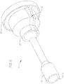
- the loader assembly 1 is a generally tubular structure that includes a loader tube 10, a hub 20, and a cap 30.
- the loader tube 10 has a first proximal end 11 with an opening for inserting a prosthetic valve in a crimped state, and a second distal end 12 with an opening through which the crimped prosthetic valve is advanced into a delivery sheath.
- the hub 20 is attached to the proximal end 11 of the loader tube 10, and includes a slot 25 that runs longitudinally along a wall of the hub 20, which in some embodiments can be used to facilitate attachment of the hub 20 around the loader tube 10.
- the cap 30 is attachable to the hub 20, for example, by a threaded engagement.
- the cap 30 and/or other portions of the loader assembly 1 can form a hemostatic seal to prevent leakage through the loader assembly 1 when the loader assembly is inserted into a delivery sheath at an access site of a patient.
- the loader tube 10 includes a tube wall that defines a bore with varying inner diameters extending from the proximal end 11 to the distal end 12.
- the loader tube 10 has a tube section 15 with an enlarged opening at the proximal end 11 and at least one portion 17 that reduces in diameter towards the distal end 12, to facilitate guiding and inserting of the delivery system and/or crimped valve through the loader tube.
- the tube section 15 has two such tapering sections 17 that reduce in diameter.
- a middle tube section 14 has a reduced inner diameter relative to other portions of the loader tube 10.
- An inner diameter of the tube section 14 is equal to or slightly larger than an outer diameter of a crimped replacement valve that has been crimped off of an expansion balloon, which in some embodiments is the smallest crimped configuration of the valve prosthesis.
- the crimped valve can be temporarily held in the middle tube section 14 of the loader tube 10 by for example, friction or interference forces against an inner wall of the tube section 14, and the crimped valve is restricted from migrating out of tube section 14 absent an additional axial force applied to either the loader assembly 1 or the valve.
- Distal to the tube section 14 is an enlarged or flared tube section 13 with an enlarged wide-mouth opening at the distal end 12. In the embodiment shown, the opening at the distal end 12 is slightly smaller than the opening at the proximal end 11.
- the flared distal section 13 is sized to retrieve and hold a crimped valve that has slightly expanded radial width than its original crimped diameter due, for example, to the valve being aligned onto a balloon.
- An axial length of the tube section 13 is equal to or greater than an axial length of a valve prosthesis when the valve prosthesis is crimped, so that the valve prosthesis can fit fully in the tube section 13 during valve retrieval.
- the different diameters between the distal tube section 13 and the middle tube section 14 forms a tapering portion 16 which serves as a hard stop for a slightly expanded valve that is being retrieved back into the loader assembly 1 through the opening at the distal end 12.
- the tapering portion 16 prevents the retrieved valve from slipping out of the proximal end 11 of the loader and potentially breaking any hemostatic seals before the loader and valve have been fully removed from the rest of the delivery system.
- the loader tube 10 can further include one or more trails of etched score marks 18a, 18b in the wall of the loader tube 10.
- two substantially parallel longitudinal lines of score marks 18a extend from the proximal end 11 of the loader tube 10, across the tube section 15, to a transition region between the tube section 15 and the tube section 14.
- An additional trail of score marks 18b extends circumferentially around the loader tube 10 approximate the region where the score marks 18a end.
- the position of the score mark 18b corresponds to a region of the loader tube 10 where the hub 20 ends when the hub 20 is attached to or bonded to the loader tube 10. Additional features and usage of the score marks 18a, 18b will be discussed in greater detail below with relation to operation of the loader assembly 1.
- the hub 20 has a first proximal end 21 and a second distal end 22.
- An axial length of the hub 20 corresponds substantially to an axial length of the proximal tube section 15 of the loader tube 10
- a shape of a circumferential wall 23 of the hub 20 corresponds substantially to the shape of the tube section 15, including one of the tapering sections 17 in the illustrated embodiment.
- the wall 23 of the hub 20 defines a coaxial bore 24 that extends through a center of the hub 20.
- a slot 25 runs longitudinally down one side of the hub 20.
- a circumferential width of the slot 25 is the same as or slightly larger than a distance between the two parallel lines of score marks 18a, so that the score marks 18a are accessible through the slot 25 when the loader tube 10 and the hub 20 are bonded or otherwise assembled together.
- the hub 20 further has an annular lip 26 adjacent to the proximal end 21 that has a larger diameter than other portions of the hub 20.
- an outer circumferential surface of the annular lip 26 is threaded or otherwise modified to facilitate engagement with the cap 30.
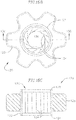
- the cap 30 is illustrated in Figs. 5A and 5B , and also has a first proximal end 31 and a second distal end 32.
- the cap 30 includes a frame 33 in the form of an annular ring.
- the frame 33 has a first portion 34 adjacent to the proximal end 31 with a substantially cylindrical inner surface, and a second portion 35 adjacent to the distal end 32 with a threaded inner surface.
- the threaded inner surface of the second portion 35 of the cap 30 is configured to interact with the threaded outer surface of the annular lip 26 of the hub 20 to attach the cap 30 to the hub 20.
- a seal 36 is attached to the first portion 34 of the frame 33.
- the seal 36 is attached to the first portion 34 of the frame 33 in one of various manners, for example, via an adhesive or other bonding means. Furthermore, the seal 36 can contribute to forming a hemostatic seal of the loader assembly 1.
- the seal 36 includes a centrally located expandable opening 37 through which a crimped valve and delivery system can pass, as will be discussed in greater detail below.
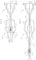
- Fig. 6 shows a cross-sectional view of an assembled loader assembly 1 according to the first embodiment.
- the hub 20 is bonded or otherwise attached to the proximal section 15 of the loader tube 10, where the inner wall of the hub 20 substantially corresponds to the outer wall of the proximal section 15 of the loader tube 10.
- the distal end 22 of the hub 20 is axially aligned with the circumferential trail of score marks 18b extending around the loader tube 10.
- the slot 25 of the hub 20 is aligned with the two lines of score marks 18a, so that the score marks 18a are exposed to the outside of the loader assembly 1 through the slot 25.
- the cap 30 is attached to the proximal end 21 of the hub 20.
- the cap 30 includes a seal 36, which can facilitate hemostasis through loader assembly 1 during a surgical or other medical procedure.
- Other seals (not shown) can also be arranged through the loader tube 10, the hub 20, or the cap 30, as needed, for maintaining hemostasis.
- a valve prosthesis delivery system 40 includes a delivery catheter 41 for supporting and advancing a transcatheter heart valve 42 and an expansion balloon 43 to an implant site.
- the delivery catheter 41 is generally tubular and has a distal end from which the valve prosthesis 42 and the balloon 43 extend.
- a guide wire 44 extends through the delivery catheter 41, the valve prosthesis 42, and the balloon 43.
- the prosthetic valve 42 is crimped around the delivery system 40, and for example, a proximal end of the prosthesis 42 can abut against an end of a feature or advancing tool of the delivery system 40 (not shown).
- the expandable balloon 43 is positioned distal to the crimped valve prosthesis 42 on the delivery catheter.
- the valve prosthesis 42 in this embodiment is crimped off of the balloon 43.
- the guide wire 44, the uninflated balloon 43, and the crimped valve 42 are inserted through the loader assembly 1.
- the various features of the delivery system 40 are first inserted through the opening 37 of the cap 30, and then advanced through the middle tube section 14 of the loader tube 10.
- the balloon 43 can be collapsed and advanced past the middle section 14, while the crimped valve 42 can be positioned in the middle section 14, where, as discussed above, the crimped valve 42 can be temporarily held.
- the loader assembly 1 holding the delivery system 40 and the crimped valve 42 is inserted into a proximal hub 51 of a delivery sheath device 50.
- the delivery sheath device 50 can be an expandable sheath system, which includes the hub 51 and an expandable sheath 52 attached to a distal end of the hub 51.
- the delivery sheath device 50 can also include one or more seals 53 to help maintain hemostasis when the sheath is positioned at an access site in a patient's body.
- the loader assembly 1 can be configured for use in conjunction with any similar delivery sheath device, and as such, specific details of the sheath device 50 that are not associated with interactions with the loader assembly 1 have been omitted for ease of description.
- the distal end 12 of the loader tube 10 is first inserted into the hub 51 while the delivery system 40 is arranged in the loader assembly 1 as previously described and illustrated with respect to Fig. 7 .
- the crimped valve 42 can first be advanced past the middle tube section 14 of the loader tube 10 into the enlarged tube section 13 and can be positioned on the balloon 43, while also slightly expanding to accommodate the balloon 43. In this manner, the valve 42 and balloon 43 assembly can be positioned and held in the distal tube section 13 when the loader assembly 1 is inserted into the hub 51 of the sheath device 50.
- the relative lengths of the loader assembly 1 and the sheath hub 51 are such that the middle tube section 14 extends out of the proximal end of the hub 51.
- the loader assembly 1 can be advanced further distally relative to the sheath device 50 when retrieval of a valve prosthesis 42 is desired, until the enlarged proximal section 15 of the loader tube 10 or the hub 20 of the loader assembly 1 abuts against a proximal end of the hub 51.
- the loader assembly 1 After the loader assembly 1 is inserted into the hub 51, the loader assembly 1 can be held at the position shown in Fig. 8 , where the distal end 12 of the loader tube 10 remains in the hub 51 of the sheath device 50. Meanwhile, the crimped valve prosthesis 42, as well as the delivery system 40 including the catheter 41, the balloon 43, and the guide wire 44, can be aligned with the sheath 52 of the sheath device 50, and then advanced through the distal end of the hub 51 and into the sheath 52.
- Fig. 9 illustrates an example of a valve prosthesis 42 positioned on balloon 43 being advanced towards the implant site.
- sheath 52 is expandable, and a portion 54 of the sheath 52 is expanded locally around the prosthesis 42 and balloon 43 assembly, for accommodating the assembly when it passes through the sheath 52.
- the loader assembly 1 can be held together with the hub 51 in the position shown in Figs. 8 and 9 during the rest of the implantation procedure, or can be pulled proximally out of the proximal end of the hub 51, and held apart from the sheath device 50 during the rest of the procedure. It shall be noted that in either of these cases, the delivery catheter 41 of the delivery system 40 still passes through both the loader assembly 1 and the hub 51.
- the crimped THV 42 can then be advanced and positioned at the implant site, and can be expanded by the balloon 43 for final implantation.
- the sheath 52 will only extend to a portion proximal to the implant site (e.g., to a location in the patient's aorta), while the delivery system 40 holding the valve prosthesis 42 exits a distal end of the sheath 52 and advances to the implant site.
- the delivery system 40 can be retrieved through the sheath 52, and the delivery system 40 and the delivery sheath device 50 can both be removed from the access site on the patient.
- retrieval of the valve prosthesis 42 may become desirable or necessary.
- the valve 42 or part of the delivery system 40 can become damaged, the valve 42 may not expand correctly, or other errors or malfunctions can occur where the physician deems it necessary to completely remove the valve 42 from the patient.
- the loader assembly 1 can be used to facilitate retrieval of the valve 42, where the loader assembly 1, the valve 42, and the delivery system 40 can be removed from the patient, while the delivery sheath device 50 remains in the body. In this manner, reinsertion or repositioning of the sheath device 50 at the patient's access site is not needed, and a new delivery system 40 and/or valve 42 can be delivered through the sheath device 50 more quickly and easily.
- removal of the entire sheath device 50 would be necessary to remove a partially expanded valve 42, since the valve 42 can damage the sheath 52 or one or more hemostatic seals 53 during the retrieval process.
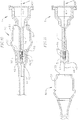
- Figs. 10 and 11 show steps of retrieving a THV 42 through the delivery sheath device 50 using the loader assembly 1.
- the delivery system 40 including the catheter 41 and the balloon 43, along with the partially expanded valve 42 positioned on the balloon 43, have already been retrieved partially through the sheath 52, but have not yet been pulled back into the hub 51.
- the loader assembly 1 has been advanced further distally into the hub 51.
- the loader assembly 1 can be inserted back into the sheath device 50 and advanced to the position illustrated in Fig. 10 prior to the valve 42 being pulled back into the hub 51.
- the loader assembly 1 has been advanced distally through the hub 51, so that the enlarged tube section 13 protrudes out of the hub 51 and into the sheath 52, where the opening at the distal end 12 of the loader tube 10 has crossed and is distal to one or more hemostatic seals 53 positioned in and/or around the hub 51.
- a length of the loader assembly 1 relative to the hub 51 allows for the distal end 12 of the loader tube to protrude into the sheath 52 before the enlarged proximal portions of the loader assembly 1 abut against the proximal end of the hub 51.
- the balloon 43 and the valve prosthesis 42 that is partially expanded thereon can be pulled back into the enlarged tube section 13 prior to contacting the hub 51 and any seals 53 associated therewith.
- the valve 42 and balloon 43 are held in the enlarged tube section 13, and the tapered section 16 acts as a hard stop against pulling the partially expanded valve 42 or the balloon 43 any further proximally through the loader tube 10. Therefore, a situation where the physician accidentally removes the valve 42 and the rest of the delivery system 40 through the loader assembly 1 before the loader assembly is removed from the sheath device 50, and potentially damaging the seal 36 of the loader assembly 1, or any other seals in the loader assembly 1 or the sheath device 50, is prevented.
- an axial length of the enlarged tube section 13 is equal to or greater than an axial length of the crimped valve prosthesis 42, when the valve 42 is held in the tube section 13, the tube section 13 completely surrounds the valve 42 and protects the sheath device 50, and specifically the seals 53 and other portions of the hub 51, from being damaged by the valve 42 and/or other portions of the delivery device 40.
- an entire system including the loader assembly 1, the delivery system 40, and the partially expanded valve 42, can then be safely pulled out from the proximal end of the hub 51 of the delivery sheath device 50.
- the enlarged tube section 13 protects the seal or seals 53 of the hub 51 from being damaged by the partially expanded valve 42 or the delivery system 40, and the tapered section 16 of the loader tube 10 keeps the valve 42 and balloon 43 in place in the tube section 13, thereby also keeping the seal 36 of the loader assembly 1 from being damaged as well. In this manner, hemostasis can be maintained during removal of the valve 42 from the patient's body, and loss of blood through either the loader assembly 1 or the sheath device 50 can be effectively prevented or minimized.
- sheath device 50 Since the sheath device 50 remains in place in the patient's body during valve removal, a quicker turnaround can be made to prepare and advance a new delivery system 40 and/or valve 42 assembly through the sheath device 50 for implantation of the valve 42 in the patient.
- the loader assembly 1 further includes one or more trails of etched score marks 18a, 18b on the loader tube.
- the score marks 18a, 18b remain exposed to the outside of the loader assembly 1 after the hub 20 is attached to the loader tube 10.
- the large tube section 15, the hub 20, and the cap 30 of the loader assembly 1 can be removed from around the catheter 41 of the delivery system 40.
- the physician can start at the proximal end 11 of the loader tube 10 and begin peeling away the portion of the loader tube 10 defined by the parallel trails of score marks 18a running inside the slot 25 of the hub 20, until the circumferential score marks 18b are reached. The physician can then peel off the proximal portion of the loader assembly 1 along the score marks 18b, and remove the proximal tube section 15, the hub 20, and the cap 30.
- the distal portion of the loader tube 10, including the middle section 14 and the distal section 13, for example, can be advanced distally completely into the hub 51, so that the seal 53 at the proximal end of the hub 51 helps maintain hemostasis in the system.
- additional longitudinal score marks can be etched into the middle section 14 and distal section 13 of the loader tube 10, so that complete removal of the loader assembly 1 from around the delivery system 1 during a procedure is possible.
- the loader tube 10 is made of a material that can be peeled apart by the physician, without any etches or score marks made in the loader tube 10.
- a second embodiment of a loader assembly for loading a THV will be described. Similar to the loader assembly discussed with respect to Figs. 1-11 , the loader assembly in Figs. 12-22 is generally configured for use with heart valve prostheses that can be radially crimped to facilitate endovascular delivery to an implant site at a patient's heart.
- the loader assembly can be used to more easily and efficiently load the crimped valve into a patient's body through a delivery sheath device or system.
- a delivery sheath device or system can be used to more easily and efficiently load the crimped valve into a patient's body through a delivery sheath device or system.
- the replacement valve can be crimped directly on a balloon expander prior to insertion into the delivery sheath and before the balloon expander has been inflated, where the crimped prosthetic valve and balloon delivery system can be inserted into the delivery sheath at the access site of the patient, and then advanced to the implant site together.
- valve prosthesis Prior to inserting a valve prosthesis into the patient's body, the valve is retrieved from a storage container or other packaging and prepped for implantation, is radially crimped or collapsed, and is then loaded into the patient's body through a sheath delivery system or other similar means.
- Valve prostheses can be individually held in storage jars or containers prior to use.
- the storage jars generally hold the valve in a glutaraldehyde solution or other similar solution or compound that effectively keeps the valve preserved and sterilized during storage.
- the valve prosthesis is removed from the storage jar and the glutaraldehyde, and is flushed or washed with saline or other similar body-compatible solution.
- the valve is then placed in a separate crimping device, where radial pressures are applied on the valve to collapse the valve to its crimped orientation.
- the crimped valve is inserted through a separate loader tube for introducing the crimped valve into a patient's body through the delivery sheath.
- a loading assembly is utilized for loading the prosthetic heart valve into a pre-positioned delivery sheath or catheter at an access site on a patient.
- the system can be assembled together, such that a storage unit, a crimper, and a loader for the valve prosthesis can be combined into a single unit.
- the loader assembly 100 includes a storage jar or container 110, a crimping apparatus or crimper 120, and a loader tube 130.
- the storage container 110 has a first proximal end 111 and a second distal end 112.
- the distal end 112 of the storage container 110 is connectable to a proximal end 121 of the crimper 120, so that a valve prosthesis that is initially housed in the container 110 can be advanced directly into the crimper 120.
- the crimper 120 further has a distal end 122 that is connectable to the loader tube 130.
- the loader tube 130 has a proximal end 131 connectable to the crimper 120 and a distal end 132 with an opening configured to facilitate advancement of the crimped valve prosthesis into a delivery sheath or other delivery catheter.
- the storage container 110 includes a generally cylindrical wall 113 extending between the ends 111, 112.
- the container 110 has an end wall 114 that forms a base or bottom of the container 110.
- the outer wall 113 and the end wall 114 define a generally cylindrical inner space 115 of the container 110.
- the space 115 has a diameter that is greater than a diameter of a fully expanded transcatheter heart valve to be held in the container 110.
- an opening 116 that facilitates access into the bore 115 from the proximal end 111 of the container 110.
- the opening 116 is sized to facilitate insertion of a collapsed balloon expander and a delivery catheter of a valve delivery system therethrough.
- an annular ring 117 defines the opening 116 through the end wall 114 and projects slightly into the inner space 115 of the container 110.
- the slightly elongated annular ring 117 can serve, for example, as a guide for correctly loading a tip of the expandable balloon, or more generally a distal end of the delivery system, through a center of the expanded valve prosthesis held in the storage container 110, and/or for properly positioning the expandable balloon through the valve prosthesis prior to advancing the valve and balloon assembly into the crimper 120.
- a second opening 118 is large enough for the expanded valve prosthesis to advance through.
- an attachment feature (not shown) is provided on an inner surface or on an outer surface of the wall 113 at the opening 118 to facilitate attachment and/or sealing between the container 110 and the crimper 120.
- the attachment feature can be, for example, threads or a lip.
- the same or different engagement features can be provided adjacent one or both the opening 116 or the opening 118 for attaching caps or seals during valve storage, before the particular valve is selected for implantation.
- the crimping apparatus 120 includes a generally tubular body 123 that extends from the first end 121 of the crimper 120 to the second end 122 of the crimper 120.
- An outer wall of the body 123 is generally cylindrical in the embodiment shown, and has openings at both the first and second ends 121, 122.
- the crimper 120 defines a central aperture or bore 126 that extends from the first end 121 to the second end 122 of the crimper 120.
- either the outer surface and/or the inner surface of the body 123 can also include one or more engagement structures, such as threads (not shown), adjacent to either the first or second ends 121, 122, or both, for engaging other parts of the assembly.
- a crimping device for crimping a transcatheter heart valve.
- the crimping device includes crimping jaws or a similar mechanism.
- the crimping jaws are formed by a plurality of wedges 124 which define a size of the central bore 126.
- the central bore 126 can be substantially cylindrical, to facilitate placement and crimping of the heart valve prosthetic therein.
- the sides of the wedges can be substantially flat, so that a polygon with a number of sides equal to the number of wedges 124 is formed to approximate a cylindrical shape.
- the wedges 124 articulate relative to one another to increase or decrease a size of the central bore 126.
- different known crimping mechanisms can instead be utilized in place of the wedges 124.
- a handle or knob 125 circumferentially surrounds an outer surface of the tubular body 123.
- the knob 125 can be shaped to include indentations and/or other features that facilitate gripping and rotating around the body 123 by a user.
- the knob 125 is mechanically coupled to the wedges 124, such that rotation of the knob 125 in one direction will cause the wedges 124 to rotate relative to one another (e.g., in the same direction), in order to increase the size of the bore 126, while rotation of the knob 125 in the opposite direction will also cause the wedges 124 to rotate relative to one another in the opposite direction to decrease the size of the bore 126.
- the crimper 120 can be configured such that the bore 126 decreases in size and then subsequently increases in size in response to rotation of the knob 125 in the same direction, in order to simplify operation.
- the loader 130 also includes a generally tubular body 133 that extends from a first end 131 of the body 133 to a second end 132 of the body 133, and that defines an inner bore 134.
- the first end 131 of the body can include an engagement structure (not shown) for engaging the crimper 120.
- the engagement structure can be on an outer surface or an inner surface of the loader tube 130, in order to complement a corresponding engagement structure on the crimper 120.
- the loader tube 130 is utilized to correctly orient and position the heart valve before the heart valve is advanced into, for example, a catheter or expandable sheath that has already been positioned in a patient's body, and in some cases, can also further reduce a size of a crimped transcatheter heart valve.
- the inner bore 134 of the loader tube 130 gradually reduces in diameter from the first end 131 to the second end 132, where a size of the opening at the second end 132 can be configured to be slightly larger than a desired diameter of the transcatheter heart valve after it has been crimped (e.g., by crimper 120), or correspond to a diameter of a crimped valve prosthesis that is desired for delivery through the patient's body.
- Figs. 17-22 illustrate a method of utilizing the loader assembly 100 for preparing, crimping, and advancing a THV for delivery through a patient's body via a delivery catheter or sheath.
- the THV Prior to assembling the various parts of the loader assembly 100 as illustrated in Fig. 17 , the THV can be stored in the storage container or housing 110.
- Various sealed storage containers 110 can, for example, hold different sized or different shaped THVs 142, and can be labeled for easy identification by a practitioner.
- each of the storage containers 110 can be sealed at both ends, with for example, a plug or cap at opening 116 (not shown) and a lid or cap at opening 118 (not shown).
- the storage container 110 holding the desired valve 142 is selected and unsealed, and the glutaraldehyde and/or other preservation/sterilization solutions are drained from the storage container 110.
- the inside of the container 110, including the valve 142 can also be washed or flushed with saline or other similar solutions to remove residual glutaraldehyde prior to implantation.
- This flushing step can be streamlined with, for example, tubes and/or stopcocks that easily connect to one or both ends of the storage container 110.
- additional openings for more effective flushing and/or draining of the storage container 110, for example, on the sides of the container 110 can also be added.
- the storage container 110 holding the valve prosthesis 142 can be attached to the first end 121 of the crimper 120.
- the loader tube 130 can be attached to the second end 122 of the crimper 120 before or after the storage container 110 has been attached to the crimper 120. As shown in Fig.
- the storage container 110 is still holding the valve prosthesis 142, while a general pathway is formed between the inner space 115 of the storage container 110, the central bore 126 of the crimper 120, and the inner bore 134 of the loader tube 130, to facilitate advancement of the valve prosthesis 142 and the associated delivery system through and out of the distal end of the loading assembly 100, via the opening at second end 132 of the loader tube 130.
- the wedges 124 of the crimper 120 are arranged so that the bore 126 has a greater diameter than a diameter of the valve prosthesis 142 in an expanded configuration, to facilitate advancement of the valve prosthesis 142 into the crimper 120 prior to being crimped.
- a delivery system 140 is advanced into the loading assembly 100.
- the delivery system 140 can include a delivery catheter 141 and an expandable balloon 143 positioned at or attached to a distal end of the delivery catheter 141.
- An additional guide wire (not shown) can further be positioned at a distal end of the expandable balloon 143.
- the delivery system 140 can be advanced through the opening 116 of the storage container 110, where the opening 116 is sized to permit insertion of the expandable balloon 143 when it the balloon 143 is in a deflated or unexpanded state.
- the balloon 143 Upon insertion of the balloon 143 through the opening 116 of the storage container 110, the balloon 143 engages the valve prosthesis 142.
- the balloon 143 engages valve leaflets of the valve prosthesis 142, and can be sized and shaped so that upon engagement or attachment with the valve prosthesis 142, the engagement is strong enough to advance the valve prosthesis 142 together with the balloon 143 out of the storage container 110 and into the bore 126 of the crimper 126, as seen in Fig. 19 .
- an additional engagement feature or accessory can be added on either the balloon 143 or the prosthetic valve 142 (not shown) to more readily facilitate proper engagement between the respective parts.
- a frictional force between the balloon 143 and the valve prosthesis 142 is sufficient to facilitate the engagement.
- the valve prosthesis 142 can instead attach to and be crimped along a shaft of the delivery catheter 141, or to another portion of the delivery system 140 other than balloon 143, based on the needs and specific operation of the particular delivery system.
- the loader tube 130 can be detached, or can remain detached, from the crimper 120, until a desired positioning of the valve prosthesis 142 and/or the delivery system 140 in the crimper 120 is achieved when viewed from the distal end 122 of the crimper 120.
- valve prosthesis 142 and the balloon 143 are still positioned in the bore 126 of the crimper 120.
- the knob 125 on the crimper 120 is turned or rotated about the loading assembly 100 by an end user, in order to rotate the wedges 124 relative to one another for making the bore 126 smaller.
- the sides of the wedges 124 apply inward radial pressure on the valve prosthesis 142 during articulation, in order to crimp the valve prosthesis 142 to a required or desired crimped or collapsed configuration.
- Fig. 20 the knob 125 on the crimper 120 is turned or rotated about the loading assembly 100 by an end user, in order to rotate the wedges 124 relative to one another for making the bore 126 smaller.
- the sides of the wedges 124 apply inward radial pressure on the valve prosthesis 142 during articulation, in order to crimp the valve prosthesis 142 to a required or desired crimped or collapsed configuration.
- the knob 125 on the crimper 120 is turned in order to make the wedges 124 shift back towards their original positions, in order to increase the size of the bore 126 in the crimper 120.
- the valve prosthesis 142 remains in the collapsed or crimped state around the balloon 143 or another corresponding portion of the delivery system 140.
- different mechanisms can be used to crimp the valve prosthesis 120 via various alternative types of crimpers.
- the delivery system 140 along with the valve prosthesis 142 can be pushed or otherwise advanced to the loader tube 130, as seen in Fig. 22 .
- a distal end 132 of the loader tube can be inserted into, for example, a delivery sheath or catheter that is already positioned in and provides access to a patient's body.
- the loader tube 130 directs the delivery system 140 and the crimped valve prosthesis 142 out through the opening at the distal end 132 of the loader tube 130 and into the delivery sheath or catheter, and thereafter the valve prosthesis 142 and delivery system 140 can be advanced to a desired implant site in the patient's body.
- the loader assemblies combine three assembly devices into a single integral and easy to use loading device.
- different storage containers and/or crimpers can be designed or modified to better interact with one another, and with different loader tubes.
- the crimper is designed to interact and connect with and/or seal to an existing loader tube, such that a pre-existing loader tube can be used with the other parts of the loading assembly, without significantly modifying the loader tube.
- the loader assembly can be designed to interact with other components used to prepare the valve prosthesis in various other ways, also without having to modify the other devices.
- the loading assembly can be made to be compatible with existing delivery systems, including existing balloon expanders and delivery catheters.
- the loading assembly can also be designed to be compatible with other preparatory features or kits, such as the Edwards QualcrimpTM crimping accessory, or other accessories that, for example, protect the leaflets from pinching on the frame or portions of the crimping tool during valve crimping.
- the described loading assemblies are discussed using storage containers that store valve prostheses in glutaraldehyde solutions or similar storage solutions, loading assemblies in other embodiments can be used with dry tissue valve technology or storage devices.
- the loading assembly can also be used with valve prostheses that are held or stored in other configurations, for example, valves that have been pre-crimped.
- valve prostheses that are held or stored in other configurations, for example, valves that have been pre-crimped.
- Various other features and/or modifications can also be envisioned in other embodiments to accommodate other variations in valves or clinical needs. In this manner, loading assemblies according to embodiments of the invention can simplify the pre-implantation procedure, reduce possible errors, and make preparation easier and less time consuming for the end user.
- a method for crimping a THV according to another embodiment of the invention will now be discussed with reference to Figs. 23-28 . While previous embodiments of the invention focused on loading assemblies for preparing and loading a THV into a patient's body, the following method focuses on methods of preparing and packaging a THV prior to delivery to a practitioner or other end user.
- THVs in their fully crimped configurations and already pre-positioned on a balloon delivery system, so that the valve prosthesis is ready to implant upon opening or removing from storage.
- storing THVs in their crimped or collapsed positions has been found to cause deformation or deterioration of the valve leaflets, and generally reduced performance by the valve leaflets once the valve prosthesis is expanded.
- transcatheter valve prostheses are still generally stored in an open or expanded configuration, and are crimped or collapsed by a practitioner or other end user just prior to implantation into a patient's body, so that the valve prostheses are held in their crimped states for a limited amount of time (e.g., only during delivery of the valve to the implant site).
- preloading prosthetic valves with a preloaded or "smart" loader or crimping device can potentially simplify the preparation process for the end user
- currently developed preloaded crimping devices still require use of the complex protective crimping accessories for protecting the valve leaflets when the valves are crimped by the end user.
- the currently developed crimping devices and processes may only be marginally better and/or easier to use than their full-sized counterparts, or do not improve or simplify the process for the end user at all, while increasing manufacturing costs.
- a method and apparatus for crimping a THV during manufacturing and packaging is provided, so that preparation by an end user is simplified, and possible damage to or deformation of the prosthetic valve can be reduced or minimized.
- a preloaded crimper or loader can be packaged with the valve prosthesis and utilized by the end user prior to implantation, without the need for an additional protective crimping accessory.
- the crimping method can be applied to valve prostheses with leaflets that have been treated for dry packaging, where the crimping method does not result in shrinkage of the leaflet tissue during packaging or storage of the valve before use.
- the crimping method can be performed on a delivery balloon or other desired portion of a delivery system, to further simplify the preparation process for the end user.
- the end user need only remove the assembly from the packaging, hydrate and/or sterilize the assembly, and then complete the crimping of the valve prosthesis before implanting the valve.
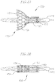
- FIG. 23 A schematic side view of a THV to which the crimping method according to embodiments of the invention can be applied is illustrated in Fig. 23 .
- the valve prosthesis 150 has an inflow section 151 and an outflow section 152.
- the valve prosthesis 150 includes a valve frame 153 that is generally cylindrical in shape and defines a bore extending between the inflow section 151 and the outflow section 152.
- the valve frame 153 is collapsible and expandable, so that the outer profile of the valve prosthesis 150 can be reduced to facilitate delivery of the valve prosthesis 150 to an implant site of a patient, and can thereafter be increased for anchoring the valve prosthesis 150 at the implant site.
- Expansion of the valve frame 153 also increases the diameter of the bore through the valve prosthesis 150, and deploys the valve leaflets therein to a final configuration or arrangement for regulating blood flow at the implant site.
- the valve leaflets have not been illustrated in the schematic valve illustrations in Figs. 23-28 .
- an outer skirt or other covering 154 can cover at least part of the valve frame 153.
- the outer skirt 154 can seal gaps between the valve prosthesis 150 and the native valve annulus at the implant site to reduce or prevent paravalvular leakage, and can also protect the surrounding tissue at the implant site after implantation.
- the outer skirt 154 covers a portion of the inflow section 151 of the valve prosthesis 150.
- the outer skirt has been illustrated in Figs. 23-28 as being a transparent layer, so that the portions of the valve frame 153 covered by the outer skirt 154 can be seen.
- the outer skirt 154 can instead be made of materials such as fabric that are translucent or opaque.
- the valve frame 153 of the THV 150 is designed with two or more rows of diamond-shaped cells at the inflow section 151 and one row of elongated hexagonal-shaped cells at the outflow section.
- the valve frame 153 is designed to reduce a delivery profile of the valve prosthesis 150, while being able to maintain radial strength in the valve upon expansion, among other features and properties.
- One example of a THV with a similar valve frame profile is the Edwards Lifesciences SAPIEN 3TM transcatheter heart valve.
- the crimping methods according to embodiments of the invention are not intended to be limited to prosthetic valves with frames similar to the ones discussed with respect to Figs. 23-28 , but rather can generally be applied to any THV with issues similar to those discussed above.
- the variations in frame cell shapes can contribute to different levels of stretching of the valve leaflets that are housed inside the valve frame.
- the diamond-shaped cells at the inflow section 151 of the valve prosthesis 150 can contribute to greater axial stretching of the valve leaflets than the hexagonal-shaped cells at the outflow section 152 of the valve prosthesis 150.
- Such differences in leaflet tissue stretching can lead to additional stresses on the leaflets during packaging or storage if a valve prosthesis 150 is stored for extended periods in its crimped state.
- shrinkage or other dimensional deformations of the leaflet tissue can be more severe at the inflow section 151 than at the outflow section 152 of the prosthetic valve 150 if the prosthetic valve 150 is stored in the crimped state.
- the shrinkage or other deformation of the leaflet tissue may occur only at or near the inflow section 151, while deformation of the leaflet tissue at or near the outflow section 152 is minimal.
- Fig. 24 illustrates a first step of a crimping method according to an embodiment of the invention.
- the crimping method can be employed during manufacturing or packaging of THVs, so that an end user receives the prosthetic valves after the crimping method has already been completed.
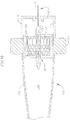
- the THV 150 is inserted into a crimping fixture or holder 160.
- the holder 160 has an outer wall 161 that defines an opening 162 into which the valve 150 is inserted.
- the opening 162 can be slightly larger than a size of the prosthetic valve 150 in its expanded state, so that the valve 150 can be held snugly in the holder 160.
- the valve is held in the holder 160 such that at least a portion of the outflow section 152 of the valve 150 still protrudes out of the holder 160. In some embodiments, a portion of the inflow section 151 also protrudes out of the holder 160.
- the holder 160 can be constructed with, for example, an inner wall or annular ridge 163 that serves as a stop for the valve 150, so that when the end of the valve 150 at the inflow section 151 abuts the wall or ridge 163, a desired amount of the outflow section 152 of the valve 150 (and in some embodiments, a part of the inflow section 151 as well) remains exposed to the outside of the holder 160.
- the wall or ridge 163 can also define a central through bore 164, to be discussed in greater detail below.
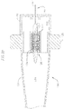
- Fig. 25 the exposed portions of the prosthetic valve 150 outside of the holder 160 are covered by a protective sheath or other protective crimping accessory (not shown).
- a delivery system 170 is then inserted through the THV 150 to a desired position.
- the delivery system can include a delivery catheter 171 and a balloon 172.
- the valve 150 can generally be crimped on the balloon 172 before the balloon 172 is expanded, but can also be crimped on any other suitable or desired portion of the delivery system 170.
- the balloon 172 can be advanced through the holder 160, such that a distal end of the balloon 172 can extend past a distal end of the valve prosthesis 150, to facilitate more versatile positioning of the balloon 172 relative to the valve prosthesis 150.
- the valve 150 can be crimped off-balloon, so that the valve 150 is not crimped on the delivery system.
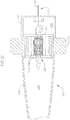
- the exposed portion of the heart valve 150, along with the protective crimping assembly, are inserted into a bore or aperture of a crimping tool 180 until the end of the holder 160 is near to or abuts against the crimping tool 180.
- the valve prosthesis 150 is first positioned through one end of the aperture of the crimper 180, and the balloon 172 of the delivery system 170 is then inserted through the valve prosthesis 150 via the other end of the aperture of the crimper 180 and arranged in a desired position prior to crimping of the valve prosthesis 150.
- the crimping tool 180 is then actuated to reduce the size of the aperture around the exposed portion of the valve 150 (e.g., as illustrated by the arrows in Fig. 26 ), in order crimp the exposed portion of the valve 150.
- the valve prosthesis 150 is crimped until the inward pressure from the crimping tool 180 is limited or stopped, for example, by the protective crimping assembly positioned around the valve prosthesis 150. In this manner, the crimping assembly can ensure that the prosthetic valve 150 is correctly positioned around and is coaxial with the balloon 172 or other suitable portion of the delivery system 170, and damage to the valve leaflets during crimping can be avoided.
- the aperture of the crimper tool 180 is then expanded, the entire assembly is removed from the crimper, and the holder 160 and protective crimping assembly (not shown) can be removed from around the valve 150, so that the heart valve 150 and delivery system 170 remain and can be packaged for delivery to an end user.
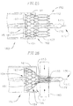
- the resulting assembly includes a partially crimped THV 150 that is crimped in a generally conical or tapered shape and positioned on a balloon catheter delivery system 170.
- the portion of the valve prosthesis 150 that was exposed outside of the holder 160 is crimped by the crimper to its collapsed state, while the portion of the valve prosthesis 150 that was held in the holder 160 remains in the expanded state.
- a transition region between the expanded and crimped portions of the valve 150 can form a substantially tapered or rounded conical shape.
- valve leaflet tissue Upon partial crimping of the prosthetic valve 150, the valve leaflet tissue is still folded or collapsed down, but stretching of the leaflet tissue in an axial direction can be reduced or minimized (e.g., since the diamond-celled portions of the valve frame 153 are not significantly stretched out) to reduce stress on the valve leaflets during storage.
- a preloaded crimper or loader can be placed around at least the remaining expanded portion of the valve prosthesis 150, and the assembly can be packaged together, so that an end user can easily remove the packaging, hydrate and/or sterilize the assembly, and use the preloaded crimper to crimp the rest of the prosthetic valve 150 to its fully crimped state around balloon 172 (e.g., as schematically illustrated in Fig. 28 ) in preparation for delivery through the patient's body.
- additional packaging steps can be applied to further simplify the end user preparation process.
- Various other ways of packaging the assemblies can also be implemented, for example, to increase shelf life or better protect the valve prostheses during storage, to facilitate easier assembly or preparation by the end user, or based on various other specific needs or requirements of different practitioners and/or patients.
- a THV can be partially crimped during manufacturing or packaging using a protective crimping assembly and/or other crimping tools.
- the prosthetic valve is crimped to a configuration where the protective crimping assembly is no longer needed to crimp the remainder of the prosthetic valve, so that the partially crimped prosthetic valve can be pre-packaged with a preloaded crimper, and without the need for the protective crimping assembly at the end user crimping step.
- the crimping method at the manufacturing stage can be tailored or adjusted to reduce or prevent shrinkage or other deformations of the leaflet tissues in the valve based on the specific characteristics of the leaflet tissues or the surrounding frame.
- portions of the inflow section 151 of the prosthetic valve 150 can be kept in the expanded or partially expanded state until the end user fully crimps the prosthetic valve 150.
- valves with leaflet tissue that have been treated or conditioned for dry packaging can be packaged in such a partially crimped manner to reduce occurrences of tissue deformation or shrinkage, thereby reducing the possibility of poor valve performance or valve malfunction.
- THVs were held in fully crimped and partially crimped states, respectively, and were subjected to heat and ethylene oxide sterilization treatments, as well as shelf life tests including four weeks of aging at room temperature while crimped. The fully crimped valves were then hydrated and expanded, while the partially crimped valves were hydrated, were fully crimped without any additional crimping accessories to simulate the end user preparation and delivery process, and were then expanded.
- valve leaflet tissue was removed from the respective frames and their dimensions were measured and further studied using a Keyence measuring system. While the leaflets from the fully crimped valves exhibited approximately 25% decreases in the top width and mid width dimensions compared to typical valves that were stored in their expanded states and only crimped prior to use, the dimensions of the leaflets of the partially crimped valves remained similar to those of their conventionally stored counterparts. Tissue shrinkage in the partially crimped valves was greatly reduced or unobserved when compared to the tissue shrinkage exhibited in the valves that were stored in their fully crimped states.
- Valves according to other embodiments can be partially crimped in different ways. For example, where an outflow section of a prosthetic valve can cause more leaflet deformation, the outflow section can be kept expanded, while the inflow section can be crimped instead of the outflow section. In still other embodiments, the entire valve prosthesis can be crimped to varying degrees, where one or more sections is crimped more significantly than other sections, based on the particular properties of each transcatheter heart valve.
- the crimping and packaging methods reduces the number of packaging components, reduces the number of preparatory steps needed prior to valve implantation, and reduces the number of operator-dependent skills that an end user needs. Simplifying the end user process will also reduce the potential for preparatory errors, such as aligning or crimping the valve in the wrong direction, or misuse of the various packaging components or assembly tools previously required for crimping the valves prior to implantation.
- a loader assembly for loading a transcatheter heart valve into a delivery sheath for delivering the heart valve into a body of a patient comprises a loader tube having a first end, a second end, and a central axis extending through the first and second ends, the loader tube comprising a tube wall defining a coaxial bore, wherein the tube wall has a first section at the first end with a first diameter, a second section connected to a distal end of the first section and having a second diameter smaller than the first diameter, and a third section connected to a distal end of the second section and having a third diameter greater than the second diameter; and at least one seal configured to maintain hemostasis in the loader tube when the coaxial bore of the loader tube is in communication with a blood vessel of the patient.
- the loader tube is separable into two or more separate parts.
- at least a portion of the first section of the loader tube has one or more score marks to facilitate separation of the loader tube into the two or more separate parts.
- the loader assembly according to any one of the first to the third embodiments further comprises a hub positioned around at least a portion of the first section of the loader tube.
- the hub has a longitudinal slot, and a portion of the loader tube is accessible through the slot to facilitate removal of the hub and the portion of the loader tube attached to the hub from other portions of the loader tube.
- the seal is on a cap that is detachable from the loader tube.
- a method of using a loader assembly to retrieve a transcatheter heart valve from a body of a patient after the heart valve and a delivery system for the heart valve have been inserted into the body through a delivery sheath that provides access into the body comprises inserting the loader assembly through a hub of the delivery sheath, such that a distal end of the loader assembly extends distally from a hemostatic seal of the hub of the delivery sheath, wherein the delivery system extends through the delivery sheath and the loader assembly; moving the heart valve and a balloon of the delivery system on which the heart valve is positioned towards the loader assembly; moving the heart valve and the balloon into a distal section of the loader assembly, wherein a width of an opening at the distal end of the loader assembly is greater than a width of the heart valve and an axial length of the distal section of the loader assembly is greater than a length of the heart valve when the heart valve is retrieved; and removing the loader assembly from a prox
- the storage container has a first end with an opening through which the heart valve can be inserted and removed, and a second end with an opening smaller than the opening at the first end for inserting a delivery system for the heart valve.
- the crimping apparatus comprises a substantially cylindrical body, a crimping aperture defining a through bore configured to expand and contract, and an outer knob configured to control the crimping aperture.
- the loader assembly of any one of the ninth to the eleventh embodiments further comprises the heart valve, wherein the heart valve is configured to be held in the storage container.
- a method of crimping a transcatheter heart valve having a first end and a second end and comprising a valve frame and a plurality of valve leaflets comprises crimping the heart valve to a first position where the first end of the heart valve is crimped from a first width to a second width smaller than the first width, while the second end of the heart valve remains at the first width; and packaging the heart valve when the heart valve is in the first position.
- the method according to the thirteenth embodiment further comprises treating the valve leaflets of the heart valve to facilitate packaging of the valve leaflets in a dry condition.
- the method according to the thirteenth or the fourteenth embodiment further comprises positioning a balloon of a balloon delivery system through the heart valve before crimping the heart valve to the first position on the balloon.
- the method according to any one of the thirteenth to the fifteenth embodiments further comprises positioning a crimping tool around at least a portion of the second end of the heart valve when the heart valve is in the first position and before packaging the heart valve, to facilitate crimping of the second end of the heart valve by an end user.
- a crimping accessory is used to crimp the first end of the heart valve, and wherein the second end of the heart valve can be crimped by the crimping tool without the crimping accessory.
- the second end of the heart valve is held in a holder to prevent crimping of the second end of the heart valve when the first end of the heart valve is crimped.
Landscapes
- Health & Medical Sciences (AREA)
- Cardiology (AREA)
- Engineering & Computer Science (AREA)
- Biomedical Technology (AREA)
- Vascular Medicine (AREA)
- Transplantation (AREA)
- Oral & Maxillofacial Surgery (AREA)
- Heart & Thoracic Surgery (AREA)
- Life Sciences & Earth Sciences (AREA)
- Animal Behavior & Ethology (AREA)
- General Health & Medical Sciences (AREA)
- Public Health (AREA)
- Veterinary Medicine (AREA)
- Mechanical Engineering (AREA)
- Prostheses (AREA)
- Media Introduction/Drainage Providing Device (AREA)
- Surgical Instruments (AREA)
Priority Applications (2)
| Application Number | Priority Date | Filing Date | Title |
|---|---|---|---|
| EP23186004.0A EP4233788B1 (de) | 2015-08-20 | 2016-08-19 | Verfahren zum crimpen einer transkatheterherzklappe |
| EP25191023.8A EP4691420A3 (de) | 2015-08-20 | 2016-08-19 | Ladevorrichtung und rückholvorrichtung für eine transkatheterherzklappe und verfahren zum crimpen einer transkatheterherzklappe |
Applications Claiming Priority (4)
| Application Number | Priority Date | Filing Date | Title |
|---|---|---|---|
| US201562207879P | 2015-08-20 | 2015-08-20 | |
| US15/238,605 US11026788B2 (en) | 2015-08-20 | 2016-08-16 | Loader and retriever for transcatheter heart valve, and methods of crimping transcatheter heart valve |
| EP16837898.2A EP3337412B1 (de) | 2015-08-20 | 2016-08-19 | Ladevorrichtung für eine transkatheterherzklappe |
| PCT/US2016/047737 WO2017031412A1 (en) | 2015-08-20 | 2016-08-19 | Loader and retriever for transcatheter heart valve, and methods of crimping transcatheter heart valve |
Related Parent Applications (1)
| Application Number | Title | Priority Date | Filing Date |
|---|---|---|---|
| EP16837898.2A Division EP3337412B1 (de) | 2015-08-20 | 2016-08-19 | Ladevorrichtung für eine transkatheterherzklappe |
Related Child Applications (2)
| Application Number | Title | Priority Date | Filing Date |
|---|---|---|---|
| EP25191023.8A Division EP4691420A3 (de) | 2015-08-20 | 2016-08-19 | Ladevorrichtung und rückholvorrichtung für eine transkatheterherzklappe und verfahren zum crimpen einer transkatheterherzklappe |
| EP23186004.0A Division EP4233788B1 (de) | 2015-08-20 | 2016-08-19 | Verfahren zum crimpen einer transkatheterherzklappe |
Publications (3)
| Publication Number | Publication Date |
|---|---|
| EP3861963A2 true EP3861963A2 (de) | 2021-08-11 |
| EP3861963A3 EP3861963A3 (de) | 2021-12-15 |
| EP3861963B1 EP3861963B1 (de) | 2023-07-19 |
Family
ID=58051674
Family Applications (4)
| Application Number | Title | Priority Date | Filing Date |
|---|---|---|---|
| EP23186004.0A Active EP4233788B1 (de) | 2015-08-20 | 2016-08-19 | Verfahren zum crimpen einer transkatheterherzklappe |
| EP16837898.2A Active EP3337412B1 (de) | 2015-08-20 | 2016-08-19 | Ladevorrichtung für eine transkatheterherzklappe |
| EP25191023.8A Pending EP4691420A3 (de) | 2015-08-20 | 2016-08-19 | Ladevorrichtung und rückholvorrichtung für eine transkatheterherzklappe und verfahren zum crimpen einer transkatheterherzklappe |
| EP21150029.3A Active EP3861963B1 (de) | 2015-08-20 | 2016-08-19 | Ladevorrichtung für eine transkatheterherzklappe |
Family Applications Before (3)
| Application Number | Title | Priority Date | Filing Date |
|---|---|---|---|
| EP23186004.0A Active EP4233788B1 (de) | 2015-08-20 | 2016-08-19 | Verfahren zum crimpen einer transkatheterherzklappe |
| EP16837898.2A Active EP3337412B1 (de) | 2015-08-20 | 2016-08-19 | Ladevorrichtung für eine transkatheterherzklappe |
| EP25191023.8A Pending EP4691420A3 (de) | 2015-08-20 | 2016-08-19 | Ladevorrichtung und rückholvorrichtung für eine transkatheterherzklappe und verfahren zum crimpen einer transkatheterherzklappe |
Country Status (5)
| Country | Link |
|---|---|
| US (4) | US11026788B2 (de) |
| EP (4) | EP4233788B1 (de) |
| CN (2) | CN113101013B (de) |
| ES (1) | ES2961650T3 (de) |
| WO (1) | WO2017031412A1 (de) |
Families Citing this family (72)
| Publication number | Priority date | Publication date | Assignee | Title |
|---|---|---|---|---|
| US8579964B2 (en) | 2010-05-05 | 2013-11-12 | Neovasc Inc. | Transcatheter mitral valve prosthesis |
| US9308087B2 (en) | 2011-04-28 | 2016-04-12 | Neovasc Tiara Inc. | Sequentially deployed transcatheter mitral valve prosthesis |
| US9554897B2 (en) | 2011-04-28 | 2017-01-31 | Neovasc Tiara Inc. | Methods and apparatus for engaging a valve prosthesis with tissue |
| US9345573B2 (en) | 2012-05-30 | 2016-05-24 | Neovasc Tiara Inc. | Methods and apparatus for loading a prosthesis onto a delivery system |
| US9572665B2 (en) | 2013-04-04 | 2017-02-21 | Neovasc Tiara Inc. | Methods and apparatus for delivering a prosthetic valve to a beating heart |
| US10188515B2 (en) | 2013-05-13 | 2019-01-29 | Medtronic Vascular Inc. | Devices and methods for crimping a medical device |
| US11026788B2 (en) * | 2015-08-20 | 2021-06-08 | Edwards Lifesciences Corporation | Loader and retriever for transcatheter heart valve, and methods of crimping transcatheter heart valve |
| JP7002451B2 (ja) | 2015-12-15 | 2022-01-20 | ニオバスク ティアラ インコーポレイテッド | 経中隔送達システム |
| CN108882981B (zh) | 2016-01-29 | 2021-08-10 | 内奥瓦斯克迪亚拉公司 | 用于防止流出阻塞的假体瓣膜 |
| US10383725B2 (en) | 2016-08-11 | 2019-08-20 | 4C Medical Technologies, Inc. | Heart chamber prosthetic valve implant with base, mesh and dome sections with single chamber anchoring for preservation, supplementation and/or replacement of native valve function |
| AU2017361296B2 (en) | 2016-11-21 | 2022-09-29 | Neovasc Inc. | Methods and systems for rapid retraction of a transcatheter heart valve delivery system |
| US10653523B2 (en) | 2017-01-19 | 2020-05-19 | 4C Medical Technologies, Inc. | Systems, methods and devices for delivery systems, methods and devices for implanting prosthetic heart valves |
| US12029647B2 (en) | 2017-03-07 | 2024-07-09 | 4C Medical Technologies, Inc. | Systems, methods and devices for prosthetic heart valve with single valve leaflet |
| EP3619135B1 (de) * | 2017-05-02 | 2021-04-21 | Medtronic Vascular Inc. | Verfahren und anordnung zur sterilisation eines nassen gelagerten herzklappenventils |
| EP3619136B1 (de) | 2017-05-02 | 2021-04-21 | Medtronic Vascular Inc. | Verpackung für eine aus einem trockenen gewebe hergestellte herzklappenprothese |
| US12036113B2 (en) | 2017-06-14 | 2024-07-16 | 4C Medical Technologies, Inc. | Delivery of heart chamber prosthetic valve implant |
| US10918473B2 (en) * | 2017-07-18 | 2021-02-16 | Edwards Lifesciences Corporation | Transcatheter heart valve storage container and crimping mechanism |
| EP3672530A4 (de) | 2017-08-25 | 2021-04-14 | Neovasc Tiara Inc. | Sequentiell eingesetzte transkatheter-mitralklappenprothese |
| CA3075819A1 (en) | 2017-10-13 | 2019-04-18 | Edwards Lifesciences Corporation | Method for sterilizing heart valves |
| CN108272487B (zh) * | 2018-02-11 | 2023-12-29 | 南京普微森医疗科技有限公司 | 一种编织支架系统 |
| WO2019195860A2 (en) | 2018-04-04 | 2019-10-10 | Vdyne, Llc | Devices and methods for anchoring transcatheter heart valve |
| AU2019298316B2 (en) * | 2018-07-06 | 2022-09-29 | Cook Medical Technologies Llc | Storage devices, loading devices, delivery systems kits, and associated methods |
| US11857441B2 (en) | 2018-09-04 | 2024-01-02 | 4C Medical Technologies, Inc. | Stent loading device |
| US10321995B1 (en) | 2018-09-20 | 2019-06-18 | Vdyne, Llc | Orthogonally delivered transcatheter heart valve replacement |
| US11071627B2 (en) | 2018-10-18 | 2021-07-27 | Vdyne, Inc. | Orthogonally delivered transcatheter heart valve frame for valve in valve prosthesis |
| US10595994B1 (en) | 2018-09-20 | 2020-03-24 | Vdyne, Llc | Side-delivered transcatheter heart valve replacement |
| US11278437B2 (en) | 2018-12-08 | 2022-03-22 | Vdyne, Inc. | Compression capable annular frames for side delivery of transcatheter heart valve replacement |
| US12186187B2 (en) | 2018-09-20 | 2025-01-07 | Vdyne, Inc. | Transcatheter deliverable prosthetic heart valves and methods of delivery |
| US11344413B2 (en) | 2018-09-20 | 2022-05-31 | Vdyne, Inc. | Transcatheter deliverable prosthetic heart valves and methods of delivery |
| US11109969B2 (en) | 2018-10-22 | 2021-09-07 | Vdyne, Inc. | Guidewire delivery of transcatheter heart valve |
| AU2019374743B2 (en) | 2018-11-08 | 2022-03-03 | Neovasc Inc. | Ventricular deployment of a transcatheter mitral valve prosthesis |
| US11253359B2 (en) | 2018-12-20 | 2022-02-22 | Vdyne, Inc. | Proximal tab for side-delivered transcatheter heart valves and methods of delivery |
| CN111374801B (zh) * | 2018-12-28 | 2024-07-12 | 上海微创心通医疗科技有限公司 | 植入物的装载工具与医疗装置 |
| WO2020146842A1 (en) | 2019-01-10 | 2020-07-16 | Vdyne, Llc | Anchor hook for side-delivery transcatheter heart valve prosthesis |
| US11185409B2 (en) | 2019-01-26 | 2021-11-30 | Vdyne, Inc. | Collapsible inner flow control component for side-delivered transcatheter heart valve prosthesis |
| US11273032B2 (en) | 2019-01-26 | 2022-03-15 | Vdyne, Inc. | Collapsible inner flow control component for side-deliverable transcatheter heart valve prosthesis |
| US12544226B2 (en) | 2019-02-14 | 2026-02-10 | 4C Medical Technologies, Inc. | Hydrophilic skirt for paravalvular leak mitigation and fit and apposition optimization for prosthetic heart valve implants |
| CA3132162A1 (en) | 2019-03-05 | 2020-09-10 | Vdyne, Inc. | Tricuspid regurgitation control devices for orthogonal transcatheter heart valve prosthesis |
| CN113747863B (zh) | 2019-03-08 | 2024-11-08 | 内奥瓦斯克迪亚拉公司 | 可取回假体递送系统 |
| US11076956B2 (en) | 2019-03-14 | 2021-08-03 | Vdyne, Inc. | Proximal, distal, and anterior anchoring tabs for side-delivered transcatheter mitral valve prosthesis |
| US11173027B2 (en) | 2019-03-14 | 2021-11-16 | Vdyne, Inc. | Side-deliverable transcatheter prosthetic valves and methods for delivering and anchoring the same |
| CN210019794U (zh) * | 2019-03-15 | 2020-02-07 | 金仕生物科技(常熟)有限公司 | 介入瓣膜系统的保护及收入辅助装置 |
| CN111182859B (zh) * | 2019-03-15 | 2021-08-27 | 金仕生物科技(常熟)有限公司 | 介入瓣膜系统的保护及收入辅助装置 |
| AU2020256195B2 (en) | 2019-04-01 | 2022-10-13 | Neovasc Inc. | Controllably deployable prosthetic valve |
| US11491006B2 (en) | 2019-04-10 | 2022-11-08 | Neovasc Tiara Inc. | Prosthetic valve with natural blood flow |
| US11452628B2 (en) | 2019-04-15 | 2022-09-27 | 4C Medical Technologies, Inc. | Loading systems for collapsible prosthetic heart valve devices and methods thereof |
| CN114072106B (zh) | 2019-05-04 | 2025-09-19 | 维迪内股份有限公司 | 用于在自体瓣环中部署侧面递送的假体心脏瓣膜的束紧装置和方法 |
| CA3282225A1 (en) | 2019-05-20 | 2026-03-02 | Neovasc Tiara Inc. | Introducer with hemostasis mechanism |
| CN110251273B (zh) * | 2019-05-23 | 2022-09-13 | 沛嘉医疗科技(苏州)有限公司 | 一种经导管输送瓣膜预装载系统装置 |
| JP7520897B2 (ja) | 2019-06-20 | 2024-07-23 | ニオバスク ティアラ インコーポレイテッド | 薄型人工補綴僧帽弁 |
| EP4480458B1 (de) | 2019-08-20 | 2026-08-12 | VDyne, Inc. | Einführungsvorrichtungen für seitlich einführbare transkatheter-prothesenklappen |
| CN114630665B (zh) | 2019-08-26 | 2025-06-17 | 维迪内股份有限公司 | 可侧面输送的经导管假体瓣膜及其输送和锚定方法 |
| WO2021146515A1 (en) | 2020-01-17 | 2021-07-22 | Vdyne, Inc. | Ventricular stability elements for side-deliverable prosthetic heart valves and methods of delivery |
| US11931253B2 (en) | 2020-01-31 | 2024-03-19 | 4C Medical Technologies, Inc. | Prosthetic heart valve delivery system: ball-slide attachment |
| US12133797B2 (en) | 2020-01-31 | 2024-11-05 | 4C Medical Technologies, Inc. | Prosthetic heart valve delivery system: paddle attachment feature |
| US12053375B2 (en) | 2020-03-05 | 2024-08-06 | 4C Medical Technologies, Inc. | Prosthetic mitral valve with improved atrial and/or annular apposition and paravalvular leakage mitigation |
| US11992403B2 (en) | 2020-03-06 | 2024-05-28 | 4C Medical Technologies, Inc. | Devices, systems and methods for improving recapture of prosthetic heart valve device with stent frame having valve support with inwardly stent cells |
| WO2021194976A1 (en) | 2020-03-26 | 2021-09-30 | Medtronic, Inc. | Clamshell iris-style crimper for medical devices |
| ES3015213T3 (en) * | 2020-06-18 | 2025-04-30 | Edwards Lifesciences Corp | Crimping methods |
| US11844713B2 (en) | 2020-08-06 | 2023-12-19 | Medtronic, Inc. | Iris-style crimpers for medical devices |
| EP4203851B1 (de) * | 2020-08-31 | 2025-02-19 | Edwards Lifesciences Corporation | Systeme und verfahren zum crimpen und zur herstellung einer vorrichtung |
| CN114191143B (zh) * | 2020-09-02 | 2025-06-06 | 上海微创心通医疗科技有限公司 | 植入物的装载工具与医疗装置 |
| CA208275S (en) * | 2021-06-21 | 2023-07-17 | Borla Ind | Transducer-protector device for medical hemodialysis lines |
| CN114681156B (zh) * | 2021-11-19 | 2023-04-21 | 鑫依医疗科技(北京)有限公司 | 一种预装介入瓣膜系统 |
| US20250144391A1 (en) * | 2022-02-15 | 2025-05-08 | Biotronik Ag | Tavi pre-assembled loading tool and procedure |
| US12588998B1 (en) | 2022-09-01 | 2026-03-31 | 4C Medical Technologies, Inc. | Prosthetic heart valve for natural blood flow |
| WO2024054445A1 (en) * | 2022-09-06 | 2024-03-14 | The Regents Of The University Of Colorado, A Body Corporate | Crimper for prosthetic heart valves |
| AU2023358759A1 (en) | 2022-10-14 | 2025-05-15 | Vdyne, Inc. | Devices and methods for delivering a prosthetic heart valve using supra-annular support |
| US20240366366A1 (en) | 2023-03-24 | 2024-11-07 | 4C Medical Technologies, Inc. | Implant delivery |
| US20240358508A1 (en) * | 2023-04-26 | 2024-10-31 | Medtronic, Inc. | Peelable advancer for delivery system |
| EP4753631A1 (de) * | 2023-08-03 | 2026-06-10 | MiRus LLC | Crimpsysteme, vorrichtungen und verfahren zur verwendung davon |
| WO2025128753A1 (en) * | 2023-12-15 | 2025-06-19 | St. Jude Medical, Cardiology Division, Inc. | Regulation of pressure differentials in interventional medical devices |
Family Cites Families (89)
| Publication number | Priority date | Publication date | Assignee | Title |
|---|---|---|---|---|
| US4035849A (en) | 1975-11-17 | 1977-07-19 | William W. Angell | Heart valve stent and process for preparing a stented heart valve prosthesis |
| US4430081A (en) * | 1981-01-06 | 1984-02-07 | Cook, Inc. | Hemostasis sheath |
| US4592340A (en) | 1984-05-02 | 1986-06-03 | Boyles Paul W | Artificial catheter means |
| US5059186A (en) * | 1988-03-07 | 1991-10-22 | Vitaphore Corporation | Percutaneous access device |
| US4994077A (en) | 1989-04-21 | 1991-02-19 | Dobben Richard L | Artificial heart valve for implantation in a blood vessel |
| US5059177A (en) | 1990-04-19 | 1991-10-22 | Cordis Corporation | Triple lumen balloon catheter |
| DK124690D0 (da) | 1990-05-18 | 1990-05-18 | Henning Rud Andersen | Klapprotes til implantering i kroppen for erstatning af naturlig klap samt kateter til brug ved implantering af en saadan klapprotese |
| US5411552A (en) | 1990-05-18 | 1995-05-02 | Andersen; Henning R. | Valve prothesis for implantation in the body and a catheter for implanting such valve prothesis |
| US5312355A (en) * | 1991-07-09 | 1994-05-17 | H L Medical Inventions, Inc. | Splittable hemostatic valve and sheath and the method for using the same |
| US5195978A (en) * | 1991-12-11 | 1993-03-23 | Baxter International Inc. | Rapid exchange over-the-wire catheter with breakaway feature |
| US5728068A (en) | 1994-06-14 | 1998-03-17 | Cordis Corporation | Multi-purpose balloon catheter |
| US5554185A (en) | 1994-07-18 | 1996-09-10 | Block; Peter C. | Inflatable prosthetic cardiovascular valve for percutaneous transluminal implantation of same |
| US5599305A (en) | 1994-10-24 | 1997-02-04 | Cardiovascular Concepts, Inc. | Large-diameter introducer sheath having hemostasis valve and removable steering mechanism |
| US5613954A (en) * | 1994-11-21 | 1997-03-25 | Stryker Corporation | Laparoscopic surgical Y-tube cannula |
| US5639274A (en) | 1995-06-02 | 1997-06-17 | Fischell; Robert E. | Integrated catheter system for balloon angioplasty and stent delivery |
| DE19532846A1 (de) | 1995-09-06 | 1997-03-13 | Georg Dr Berg | Ventileinrichtung |
| US5591195A (en) | 1995-10-30 | 1997-01-07 | Taheri; Syde | Apparatus and method for engrafting a blood vessel |
| US6217585B1 (en) | 1996-08-16 | 2001-04-17 | Converge Medical, Inc. | Mechanical stent and graft delivery system |
| AU739710B2 (en) | 1996-08-23 | 2001-10-18 | Boston Scientific Limited | Stent delivery system having stent securement apparatus |
| US5968068A (en) | 1996-09-12 | 1999-10-19 | Baxter International Inc. | Endovascular delivery system |
| EP0850607A1 (de) | 1996-12-31 | 1998-07-01 | Cordis Corporation | Klappenprothese zur Implantation in Körperkanälen |
| US5911710A (en) * | 1997-05-02 | 1999-06-15 | Schneider/Namic | Medical insertion device with hemostatic valve |
| US5951518A (en) * | 1997-10-31 | 1999-09-14 | Teleflex, Incorporated | Introducing device with flared sheath end |
| US6527979B2 (en) | 1999-08-27 | 2003-03-04 | Corazon Technologies, Inc. | Catheter systems and methods for their use in the treatment of calcified vascular occlusions |
| US6425916B1 (en) * | 1999-02-10 | 2002-07-30 | Michi E. Garrison | Methods and devices for implanting cardiac valves |
| DE19907646A1 (de) | 1999-02-23 | 2000-08-24 | Georg Berg | Ventileinrichtung zum Einsetzen in ein Hohlorgan |
| FR2800984B1 (fr) | 1999-11-17 | 2001-12-14 | Jacques Seguin | Dispositif de remplacement d'une valve cardiaque par voie percutanee |
| US7018406B2 (en) | 1999-11-17 | 2006-03-28 | Corevalve Sa | Prosthetic valve for transluminal delivery |
| FR2815844B1 (fr) | 2000-10-31 | 2003-01-17 | Jacques Seguin | Support tubulaire de mise en place, par voie percutanee, d'une valve cardiaque de remplacement |
| US6458153B1 (en) | 1999-12-31 | 2002-10-01 | Abps Venture One, Ltd. | Endoluminal cardiac and venous valve prostheses and methods of manufacture and delivery thereof |
| KR100880550B1 (ko) | 2000-01-31 | 2009-01-30 | 쿠크 바이오텍, 인코포레이티드 | 판막 기구 및 심장 판막 기구 |
| US6454799B1 (en) | 2000-04-06 | 2002-09-24 | Edwards Lifesciences Corporation | Minimally-invasive heart valves and methods of use |
| WO2002022054A1 (en) | 2000-09-12 | 2002-03-21 | Gabbay S | Valvular prosthesis and method of using same |
| US7510572B2 (en) | 2000-09-12 | 2009-03-31 | Shlomo Gabbay | Implantation system for delivery of a heart valve prosthesis |
| US6461382B1 (en) | 2000-09-22 | 2002-10-08 | Edwards Lifesciences Corporation | Flexible heart valve having moveable commissures |
| WO2002047575A2 (en) | 2000-12-15 | 2002-06-20 | Angiomed Gmbh & Co. Medizintechnik Kg | Stent with valve |
| US7556646B2 (en) | 2001-09-13 | 2009-07-07 | Edwards Lifesciences Corporation | Methods and apparatuses for deploying minimally-invasive heart valves |
| US6733525B2 (en) | 2001-03-23 | 2004-05-11 | Edwards Lifesciences Corporation | Rolled minimally-invasive heart valves and methods of use |
| US7374571B2 (en) | 2001-03-23 | 2008-05-20 | Edwards Lifesciences Corporation | Rolled minimally-invasive heart valves and methods of manufacture |
| US6893460B2 (en) | 2001-10-11 | 2005-05-17 | Percutaneous Valve Technologies Inc. | Implantable prosthetic valve |
| US7137184B2 (en) | 2002-09-20 | 2006-11-21 | Edwards Lifesciences Corporation | Continuous heart valve support frame and method of manufacture |
| WO2004096100A1 (en) | 2003-04-24 | 2004-11-11 | Cook Incorporated | Artificial valve prosthesis with improved flow dynamics |
| US7241276B2 (en) * | 2003-08-06 | 2007-07-10 | Trivascular, Inc. | Passive hemostatic sheath valve |
| US20050154441A1 (en) * | 2004-01-14 | 2005-07-14 | Cook Incorporated | Introducer |
| WO2005084595A1 (en) | 2004-02-27 | 2005-09-15 | Cardiacmd, Inc. | Prosthetic heart valve delivery systems and methods |
| BRPI0510107A (pt) | 2004-04-23 | 2007-09-25 | 3F Therapeutics Inc | válvula protéica implantável |
| CA2580053C (en) | 2004-09-14 | 2014-07-08 | Edwards Lifesciences Ag. | Device and method for treatment of heart valve regurgitation |
| SE531468C2 (sv) | 2005-04-21 | 2009-04-14 | Edwards Lifesciences Ag | En anordning för styrning av blodflöde |
| JP4754626B2 (ja) | 2005-04-28 | 2011-08-24 | セント・ジュード・メディカル・エイトリアル・フィブリレーション・ディヴィジョン・インコーポレーテッド | カテーテル又はシース用の裂開可能な非外傷性先端及び本体 |
| US8357190B2 (en) * | 2005-05-10 | 2013-01-22 | Cook Medical Technologies Llc | Laparoscopic vascular access |
| JP4912395B2 (ja) | 2005-05-24 | 2012-04-11 | エドワーズ ライフサイエンシーズ コーポレイション | 迅速配置式補綴用心臓弁 |
| US7780723B2 (en) | 2005-06-13 | 2010-08-24 | Edwards Lifesciences Corporation | Heart valve delivery system |
| US8167932B2 (en) | 2005-10-18 | 2012-05-01 | Edwards Lifesciences Corporation | Heart valve delivery system with valve catheter |
| US8778017B2 (en) | 2005-10-26 | 2014-07-15 | Cardiosolutions, Inc. | Safety for mitral valve implant |
| US7785366B2 (en) | 2005-10-26 | 2010-08-31 | Maurer Christopher W | Mitral spacer |
| US8449606B2 (en) | 2005-10-26 | 2013-05-28 | Cardiosolutions, Inc. | Balloon mitral spacer |
| CA2631662C (en) | 2005-12-07 | 2014-08-05 | Arbor Surgical Technologies, Inc. | Connection systems for two piece prosthetic heart valve assemblies |
| US8147541B2 (en) | 2006-02-27 | 2012-04-03 | Aortx, Inc. | Methods and devices for delivery of prosthetic heart valves and other prosthetics |
| US20070239254A1 (en) * | 2006-04-07 | 2007-10-11 | Chris Chia | System for percutaneous delivery and removal of a prosthetic valve |
| ATE470410T1 (de) * | 2006-09-08 | 2010-06-15 | Edwards Lifesciences Corp | Integriertes system zum einsatz eines herzventils |
| US8029556B2 (en) | 2006-10-04 | 2011-10-04 | Edwards Lifesciences Corporation | Method and apparatus for reshaping a ventricle |
| JP5025224B2 (ja) | 2006-10-25 | 2012-09-12 | 株式会社アドバンテスト | 試験装置、ドライバコンパレータチップ、応答測定装置および校正方法 |
| US8236045B2 (en) * | 2006-12-22 | 2012-08-07 | Edwards Lifesciences Corporation | Implantable prosthetic valve assembly and method of making the same |
| US8105375B2 (en) * | 2007-01-19 | 2012-01-31 | The Cleveland Clinic Foundation | Method for implanting a cardiovascular valve |
| US20080294230A1 (en) | 2007-05-24 | 2008-11-27 | Cook Incorporated | Apparatus and methods for deploying self-expanding stents |
| AU2008268632B2 (en) * | 2007-06-22 | 2013-10-17 | Medical Components, Inc. | Tearaway sheath assembly with hemostasis valve |
| US8747458B2 (en) * | 2007-08-20 | 2014-06-10 | Medtronic Ventor Technologies Ltd. | Stent loading tool and method for use thereof |
| US8663320B2 (en) * | 2007-12-04 | 2014-03-04 | Cook Medical Technologies Llc | Storage and loading system for implantable medical devices |
| HRP20211382T1 (hr) | 2007-12-14 | 2021-12-24 | Edwards Lifesciences Corporation | Okvir za pričvršćivanje listića za protetski zalistak |
| US20090276040A1 (en) | 2008-05-01 | 2009-11-05 | Edwards Lifesciences Corporation | Device and method for replacing mitral valve |
| US9061119B2 (en) | 2008-05-09 | 2015-06-23 | Edwards Lifesciences Corporation | Low profile delivery system for transcatheter heart valve |
| US8323335B2 (en) | 2008-06-20 | 2012-12-04 | Edwards Lifesciences Corporation | Retaining mechanisms for prosthetic valves and methods for using |
| US8652202B2 (en) | 2008-08-22 | 2014-02-18 | Edwards Lifesciences Corporation | Prosthetic heart valve and delivery apparatus |
| CA2961053C (en) | 2009-04-15 | 2019-04-30 | Edwards Lifesciences Cardiaq Llc | Vascular implant and delivery system |
| US8439970B2 (en) | 2009-07-14 | 2013-05-14 | Edwards Lifesciences Corporation | Transapical delivery system for heart valves |
| WO2011022658A1 (en) | 2009-08-20 | 2011-02-24 | Cook Incorporated | Loading apparatus and system for expandable intraluminal medical devices |
| US8808248B2 (en) * | 2009-10-15 | 2014-08-19 | Biosense Webster, Inc. | Catheter sheath introducer with rotational lock |
| US8869982B2 (en) * | 2009-12-18 | 2014-10-28 | Edwards Lifesciences Corporation | Prosthetic heart valve packaging and deployment system |
| US9414914B2 (en) | 2010-02-24 | 2016-08-16 | Medtronic Ventor Technologies Ltd. | Catheter assembly with valve crimping accessories |
| EP2361651B1 (de) * | 2010-02-25 | 2016-04-27 | Biotronik AG | System aus einer Schutzhülse und einem medizinischen Gerät sowie Verfahren zur Herstellung desselben |
| US8361144B2 (en) | 2010-03-01 | 2013-01-29 | Colibri Heart Valve Llc | Percutaneously deliverable heart valve and methods associated therewith |
| FI4233795T3 (fi) | 2010-10-05 | 2024-09-09 | Edwards Lifesciences Corp | Keinosydänläppä |
| US20120172981A1 (en) | 2011-01-05 | 2012-07-05 | Curia, Inc. | Prosthetic valves formed with supporting structure and isotropic filter screen leaflets |
| US9155619B2 (en) * | 2011-02-25 | 2015-10-13 | Edwards Lifesciences Corporation | Prosthetic heart valve delivery apparatus |
| EP2520251A1 (de) * | 2011-05-05 | 2012-11-07 | Symetis SA | Verfahren und Vorrichtung zum Zusammendrücken von Stentklappen |
| WO2013016519A2 (en) * | 2011-07-28 | 2013-01-31 | St. Jude Medical, Cardiology Division, Inc. | System for loading a collapsible heart valve |
| US8652145B2 (en) | 2011-12-14 | 2014-02-18 | Edwards Lifesciences Corporation | System and method for crimping a prosthetic valve |
| US9308569B2 (en) * | 2013-02-01 | 2016-04-12 | Medtronic, Inc. | Devices and methods for crimping and loading a medical device into a delivery system |
| US11026788B2 (en) * | 2015-08-20 | 2021-06-08 | Edwards Lifesciences Corporation | Loader and retriever for transcatheter heart valve, and methods of crimping transcatheter heart valve |
-
2016
- 2016-08-16 US US15/238,605 patent/US11026788B2/en active Active
- 2016-08-19 CN CN202110404772.1A patent/CN113101013B/zh active Active
- 2016-08-19 EP EP23186004.0A patent/EP4233788B1/de active Active
- 2016-08-19 CN CN201680060691.1A patent/CN108348270B/zh active Active
- 2016-08-19 EP EP16837898.2A patent/EP3337412B1/de active Active
- 2016-08-19 EP EP25191023.8A patent/EP4691420A3/de active Pending
- 2016-08-19 WO PCT/US2016/047737 patent/WO2017031412A1/en not_active Ceased
- 2016-08-19 EP EP21150029.3A patent/EP3861963B1/de active Active
- 2016-08-19 ES ES21150029T patent/ES2961650T3/es active Active
-
2021
- 2021-06-03 US US17/338,535 patent/US11957579B2/en active Active
-
2023
- 2023-12-11 US US18/535,242 patent/US12295842B2/en active Active
-
2025
- 2025-04-11 US US19/176,451 patent/US20250235311A1/en active Pending
Also Published As
| Publication number | Publication date |
|---|---|
| CN108348270B (zh) | 2021-05-04 |
| CN113101013A (zh) | 2021-07-13 |
| EP3337412A4 (de) | 2019-03-20 |
| US20210290386A1 (en) | 2021-09-23 |
| EP3861963A3 (de) | 2021-12-15 |
| US20250235311A1 (en) | 2025-07-24 |
| EP4233788B1 (de) | 2025-07-23 |
| CN108348270A (zh) | 2018-07-31 |
| WO2017031412A1 (en) | 2017-02-23 |
| EP3337412B1 (de) | 2021-01-06 |
| US20170049567A1 (en) | 2017-02-23 |
| US11957579B2 (en) | 2024-04-16 |
| CN113101013B (zh) | 2024-09-13 |
| ES2961650T3 (es) | 2024-03-13 |
| EP4691420A2 (de) | 2026-02-11 |
| EP3337412A1 (de) | 2018-06-27 |
| US20240099838A1 (en) | 2024-03-28 |
| EP4691420A3 (de) | 2026-04-08 |
| US11026788B2 (en) | 2021-06-08 |
| EP4233788A2 (de) | 2023-08-30 |
| EP3861963B1 (de) | 2023-07-19 |
| EP4233788A3 (de) | 2023-11-15 |
| US12295842B2 (en) | 2025-05-13 |
Similar Documents
| Publication | Publication Date | Title |
|---|---|---|
| US12295842B2 (en) | Loader and retriever for transcatheter heart valve, and methods of crimping transcatheter heart valve | |
| JP5986202B2 (ja) | 折畳み可能な心臓弁を装填するためのシステム | |
| US7967138B2 (en) | Packaging systems for percutaneously deliverable bioprosthetic valves | |
| US9078781B2 (en) | Sterile cover for compressible stents used in percutaneous device delivery systems | |
| EP3383323B1 (de) | Aufbewahrungsanordnung für ein prothesenventil | |
| CN105142578B (zh) | 用于确保人工心脏瓣膜安全和快速部署的系统和方法 | |
| ES3025714T3 (en) | Systems and methods for crimping and device preparation | |
| EP2613738B1 (de) | Chirurgische herzklappen | |
| JP6042432B2 (ja) | 折畳み可能な心臓弁を装填するためのシステム | |
| CN104994812A (zh) | 用于接管和/或临时或部分支撑心脏中的天然瓣膜的短时间置换的瓣膜及其递送方法 | |
| US20250099242A1 (en) | Leaflet perforation tools and associated methods | |
| US20240180698A1 (en) | Delivery catheter, implant delivery system, and working method | |
| CN117257520A (zh) | 具有缝线张紧器的缝线锁组件 | |
| US20250248813A1 (en) | Loader Sheath and Methods for Preparing Prosthetic Heart Valve Delivery System | |
| WO2024158626A1 (en) | Implant delivery and delivery system retrieval | |
| HK1187517B (en) | Surgical heart valves |
Legal Events
| Date | Code | Title | Description |
|---|---|---|---|
| PUAI | Public reference made under article 153(3) epc to a published international application that has entered the european phase |
Free format text: ORIGINAL CODE: 0009012 |
|
| STAA | Information on the status of an ep patent application or granted ep patent |
Free format text: STATUS: THE APPLICATION HAS BEEN PUBLISHED |
|
| AC | Divisional application: reference to earlier application |
Ref document number: 3337412 Country of ref document: EP Kind code of ref document: P |
|
| AK | Designated contracting states |
Kind code of ref document: A2 Designated state(s): AL AT BE BG CH CY CZ DE DK EE ES FI FR GB GR HR HU IE IS IT LI LT LU LV MC MK MT NL NO PL PT RO RS SE SI SK SM TR |
|
| PUAL | Search report despatched |
Free format text: ORIGINAL CODE: 0009013 |
|
| AK | Designated contracting states |
Kind code of ref document: A3 Designated state(s): AL AT BE BG CH CY CZ DE DK EE ES FI FR GB GR HR HU IE IS IT LI LT LU LV MC MK MT NL NO PL PT RO RS SE SI SK SM TR |
|
| RIC1 | Information provided on ipc code assigned before grant |
Ipc: A61F 2/00 20060101ALI20211110BHEP Ipc: A61B 17/3205 20060101ALI20211110BHEP Ipc: A61B 17/00 20060101ALI20211110BHEP Ipc: A61B 17/32 20060101ALI20211110BHEP Ipc: A61F 2/95 20130101ALI20211110BHEP Ipc: A61F 2/24 20060101AFI20211110BHEP |
|
| STAA | Information on the status of an ep patent application or granted ep patent |
Free format text: STATUS: REQUEST FOR EXAMINATION WAS MADE |
|
| 17P | Request for examination filed |
Effective date: 20220615 |
|
| RBV | Designated contracting states (corrected) |
Designated state(s): AL AT BE BG CH CY CZ DE DK EE ES FI FR GB GR HR HU IE IS IT LI LT LU LV MC MK MT NL NO PL PT RO RS SE SI SK SM TR |
|
| GRAP | Despatch of communication of intention to grant a patent |
Free format text: ORIGINAL CODE: EPIDOSNIGR1 |
|
| STAA | Information on the status of an ep patent application or granted ep patent |
Free format text: STATUS: GRANT OF PATENT IS INTENDED |
|
| INTG | Intention to grant announced |
Effective date: 20230201 |
|
| RIN1 | Information on inventor provided before grant (corrected) |
Inventor name: LINDSTROM, JEFF Inventor name: NAGPURWALA, TARANNUM Inventor name: CHANG, ARVIN, T. Inventor name: BIRAN, RAZ Inventor name: NGUYEN, THANH, V. Inventor name: METCHIK, ASHER, L. |
|
| GRAS | Grant fee paid |
Free format text: ORIGINAL CODE: EPIDOSNIGR3 |
|
| GRAA | (expected) grant |
Free format text: ORIGINAL CODE: 0009210 |
|
| STAA | Information on the status of an ep patent application or granted ep patent |
Free format text: STATUS: THE PATENT HAS BEEN GRANTED |
|
| AC | Divisional application: reference to earlier application |
Ref document number: 3337412 Country of ref document: EP Kind code of ref document: P |
|
| AK | Designated contracting states |
Kind code of ref document: B1 Designated state(s): AL AT BE BG CH CY CZ DE DK EE ES FI FR GB GR HR HU IE IS IT LI LT LU LV MC MK MT NL NO PL PT RO RS SE SI SK SM TR |
|
| REG | Reference to a national code |
Ref country code: GB Ref legal event code: FG4D |
|
| REG | Reference to a national code |
Ref country code: CH Ref legal event code: EP |
|
| REG | Reference to a national code |
Ref country code: DE Ref legal event code: R096 Ref document number: 602016081278 Country of ref document: DE |
|
| REG | Reference to a national code |
Ref country code: IE Ref legal event code: FG4D |
|
| P01 | Opt-out of the competence of the unified patent court (upc) registered |
Effective date: 20230718 |
|
| REG | Reference to a national code |
Ref country code: NL Ref legal event code: FP |
|
| REG | Reference to a national code |
Ref country code: LT Ref legal event code: MG9D |
|
| REG | Reference to a national code |
Ref country code: AT Ref legal event code: MK05 Ref document number: 1588738 Country of ref document: AT Kind code of ref document: T Effective date: 20230719 |
|
| PG25 | Lapsed in a contracting state [announced via postgrant information from national office to epo] |
Ref country code: GR Free format text: LAPSE BECAUSE OF FAILURE TO SUBMIT A TRANSLATION OF THE DESCRIPTION OR TO PAY THE FEE WITHIN THE PRESCRIBED TIME-LIMIT Effective date: 20231020 |
|
| PG25 | Lapsed in a contracting state [announced via postgrant information from national office to epo] |
Ref country code: IS Free format text: LAPSE BECAUSE OF FAILURE TO SUBMIT A TRANSLATION OF THE DESCRIPTION OR TO PAY THE FEE WITHIN THE PRESCRIBED TIME-LIMIT Effective date: 20231119 |
|
| PG25 | Lapsed in a contracting state [announced via postgrant information from national office to epo] |
Ref country code: SE Free format text: LAPSE BECAUSE OF FAILURE TO SUBMIT A TRANSLATION OF THE DESCRIPTION OR TO PAY THE FEE WITHIN THE PRESCRIBED TIME-LIMIT Effective date: 20230719 Ref country code: RS Free format text: LAPSE BECAUSE OF FAILURE TO SUBMIT A TRANSLATION OF THE DESCRIPTION OR TO PAY THE FEE WITHIN THE PRESCRIBED TIME-LIMIT Effective date: 20230719 Ref country code: PT Free format text: LAPSE BECAUSE OF FAILURE TO SUBMIT A TRANSLATION OF THE DESCRIPTION OR TO PAY THE FEE WITHIN THE PRESCRIBED TIME-LIMIT Effective date: 20231120 Ref country code: NO Free format text: LAPSE BECAUSE OF FAILURE TO SUBMIT A TRANSLATION OF THE DESCRIPTION OR TO PAY THE FEE WITHIN THE PRESCRIBED TIME-LIMIT Effective date: 20231019 Ref country code: LV Free format text: LAPSE BECAUSE OF FAILURE TO SUBMIT A TRANSLATION OF THE DESCRIPTION OR TO PAY THE FEE WITHIN THE PRESCRIBED TIME-LIMIT Effective date: 20230719 Ref country code: LT Free format text: LAPSE BECAUSE OF FAILURE TO SUBMIT A TRANSLATION OF THE DESCRIPTION OR TO PAY THE FEE WITHIN THE PRESCRIBED TIME-LIMIT Effective date: 20230719 Ref country code: IS Free format text: LAPSE BECAUSE OF FAILURE TO SUBMIT A TRANSLATION OF THE DESCRIPTION OR TO PAY THE FEE WITHIN THE PRESCRIBED TIME-LIMIT Effective date: 20231119 Ref country code: HR Free format text: LAPSE BECAUSE OF FAILURE TO SUBMIT A TRANSLATION OF THE DESCRIPTION OR TO PAY THE FEE WITHIN THE PRESCRIBED TIME-LIMIT Effective date: 20230719 Ref country code: GR Free format text: LAPSE BECAUSE OF FAILURE TO SUBMIT A TRANSLATION OF THE DESCRIPTION OR TO PAY THE FEE WITHIN THE PRESCRIBED TIME-LIMIT Effective date: 20231020 Ref country code: FI Free format text: LAPSE BECAUSE OF FAILURE TO SUBMIT A TRANSLATION OF THE DESCRIPTION OR TO PAY THE FEE WITHIN THE PRESCRIBED TIME-LIMIT Effective date: 20230719 Ref country code: AT Free format text: LAPSE BECAUSE OF FAILURE TO SUBMIT A TRANSLATION OF THE DESCRIPTION OR TO PAY THE FEE WITHIN THE PRESCRIBED TIME-LIMIT Effective date: 20230719 |
|
| PG25 | Lapsed in a contracting state [announced via postgrant information from national office to epo] |
Ref country code: PL Free format text: LAPSE BECAUSE OF FAILURE TO SUBMIT A TRANSLATION OF THE DESCRIPTION OR TO PAY THE FEE WITHIN THE PRESCRIBED TIME-LIMIT Effective date: 20230719 |
|
| REG | Reference to a national code |
Ref country code: ES Ref legal event code: FG2A Ref document number: 2961650 Country of ref document: ES Kind code of ref document: T3 Effective date: 20240313 |
|
| PG25 | Lapsed in a contracting state [announced via postgrant information from national office to epo] |
Ref country code: LU Free format text: LAPSE BECAUSE OF NON-PAYMENT OF DUE FEES Effective date: 20230819 |
|
| REG | Reference to a national code |
Ref country code: DE Ref legal event code: R097 Ref document number: 602016081278 Country of ref document: DE |
|
| PG25 | Lapsed in a contracting state [announced via postgrant information from national office to epo] |
Ref country code: SM Free format text: LAPSE BECAUSE OF FAILURE TO SUBMIT A TRANSLATION OF THE DESCRIPTION OR TO PAY THE FEE WITHIN THE PRESCRIBED TIME-LIMIT Effective date: 20230719 Ref country code: RO Free format text: LAPSE BECAUSE OF FAILURE TO SUBMIT A TRANSLATION OF THE DESCRIPTION OR TO PAY THE FEE WITHIN THE PRESCRIBED TIME-LIMIT Effective date: 20230719 Ref country code: LU Free format text: LAPSE BECAUSE OF NON-PAYMENT OF DUE FEES Effective date: 20230819 Ref country code: EE Free format text: LAPSE BECAUSE OF FAILURE TO SUBMIT A TRANSLATION OF THE DESCRIPTION OR TO PAY THE FEE WITHIN THE PRESCRIBED TIME-LIMIT Effective date: 20230719 Ref country code: DK Free format text: LAPSE BECAUSE OF FAILURE TO SUBMIT A TRANSLATION OF THE DESCRIPTION OR TO PAY THE FEE WITHIN THE PRESCRIBED TIME-LIMIT Effective date: 20230719 Ref country code: CZ Free format text: LAPSE BECAUSE OF FAILURE TO SUBMIT A TRANSLATION OF THE DESCRIPTION OR TO PAY THE FEE WITHIN THE PRESCRIBED TIME-LIMIT Effective date: 20230719 Ref country code: SK Free format text: LAPSE BECAUSE OF FAILURE TO SUBMIT A TRANSLATION OF THE DESCRIPTION OR TO PAY THE FEE WITHIN THE PRESCRIBED TIME-LIMIT Effective date: 20230719 Ref country code: MC Free format text: LAPSE BECAUSE OF FAILURE TO SUBMIT A TRANSLATION OF THE DESCRIPTION OR TO PAY THE FEE WITHIN THE PRESCRIBED TIME-LIMIT Effective date: 20230719 |
|
| REG | Reference to a national code |
Ref country code: BE Ref legal event code: MM Effective date: 20230831 |
|
| PLBE | No opposition filed within time limit |
Free format text: ORIGINAL CODE: 0009261 |
|
| STAA | Information on the status of an ep patent application or granted ep patent |
Free format text: STATUS: NO OPPOSITION FILED WITHIN TIME LIMIT |
|
| 26N | No opposition filed |
Effective date: 20240422 |
|
| PG25 | Lapsed in a contracting state [announced via postgrant information from national office to epo] |
Ref country code: SI Free format text: LAPSE BECAUSE OF FAILURE TO SUBMIT A TRANSLATION OF THE DESCRIPTION OR TO PAY THE FEE WITHIN THE PRESCRIBED TIME-LIMIT Effective date: 20230719 |
|
| PG25 | Lapsed in a contracting state [announced via postgrant information from national office to epo] |
Ref country code: BE Free format text: LAPSE BECAUSE OF NON-PAYMENT OF DUE FEES Effective date: 20230831 |
|
| PG25 | Lapsed in a contracting state [announced via postgrant information from national office to epo] |
Ref country code: BG Free format text: LAPSE BECAUSE OF FAILURE TO SUBMIT A TRANSLATION OF THE DESCRIPTION OR TO PAY THE FEE WITHIN THE PRESCRIBED TIME-LIMIT Effective date: 20230719 |
|
| PG25 | Lapsed in a contracting state [announced via postgrant information from national office to epo] |
Ref country code: BG Free format text: LAPSE BECAUSE OF FAILURE TO SUBMIT A TRANSLATION OF THE DESCRIPTION OR TO PAY THE FEE WITHIN THE PRESCRIBED TIME-LIMIT Effective date: 20230719 |
|
| PG25 | Lapsed in a contracting state [announced via postgrant information from national office to epo] |
Ref country code: CY Free format text: LAPSE BECAUSE OF FAILURE TO SUBMIT A TRANSLATION OF THE DESCRIPTION OR TO PAY THE FEE WITHIN THE PRESCRIBED TIME-LIMIT; INVALID AB INITIO Effective date: 20160819 |
|
| PG25 | Lapsed in a contracting state [announced via postgrant information from national office to epo] |
Ref country code: HU Free format text: LAPSE BECAUSE OF FAILURE TO SUBMIT A TRANSLATION OF THE DESCRIPTION OR TO PAY THE FEE WITHIN THE PRESCRIBED TIME-LIMIT; INVALID AB INITIO Effective date: 20160819 |
|
| PGFP | Annual fee paid to national office [announced via postgrant information from national office to epo] |
Ref country code: NL Payment date: 20250704 Year of fee payment: 10 |
|
| PGFP | Annual fee paid to national office [announced via postgrant information from national office to epo] |
Ref country code: ES Payment date: 20250905 Year of fee payment: 10 |
|
| PGFP | Annual fee paid to national office [announced via postgrant information from national office to epo] |
Ref country code: DE Payment date: 20250624 Year of fee payment: 10 |
|
| PGFP | Annual fee paid to national office [announced via postgrant information from national office to epo] |
Ref country code: IT Payment date: 20250722 Year of fee payment: 10 |
|
| PGFP | Annual fee paid to national office [announced via postgrant information from national office to epo] |
Ref country code: CH Payment date: 20250901 Year of fee payment: 10 |
|
| PG25 | Lapsed in a contracting state [announced via postgrant information from national office to epo] |
Ref country code: TR Free format text: LAPSE BECAUSE OF FAILURE TO SUBMIT A TRANSLATION OF THE DESCRIPTION OR TO PAY THE FEE WITHIN THE PRESCRIBED TIME-LIMIT Effective date: 20230719 |
|
| PGFP | Annual fee paid to national office [announced via postgrant information from national office to epo] |
Ref country code: GB Payment date: 20260630 Year of fee payment: 11 |
|
| PGFP | Annual fee paid to national office [announced via postgrant information from national office to epo] |
Ref country code: IE Payment date: 20260619 Year of fee payment: 11 |
|
| PGFP | Annual fee paid to national office [announced via postgrant information from national office to epo] |
Ref country code: FR Payment date: 20260608 Year of fee payment: 11 |