EP3861904A1 - Hachoir manuel à double système d'étanchéité - Google Patents
Hachoir manuel à double système d'étanchéité Download PDFInfo
- Publication number
- EP3861904A1 EP3861904A1 EP21151874.1A EP21151874A EP3861904A1 EP 3861904 A1 EP3861904 A1 EP 3861904A1 EP 21151874 A EP21151874 A EP 21151874A EP 3861904 A1 EP3861904 A1 EP 3861904A1
- Authority
- EP
- European Patent Office
- Prior art keywords
- cover
- seal
- bowl
- food preparation
- preparation apparatus
- Prior art date
- Legal status (The legal status is an assumption and is not a legal conclusion. Google has not performed a legal analysis and makes no representation as to the accuracy of the status listed.)
- Granted
Links
Images



Classifications
-
- A—HUMAN NECESSITIES
- A47—FURNITURE; DOMESTIC ARTICLES OR APPLIANCES; COFFEE MILLS; SPICE MILLS; SUCTION CLEANERS IN GENERAL
- A47J—KITCHEN EQUIPMENT; COFFEE MILLS; SPICE MILLS; APPARATUS FOR MAKING BEVERAGES
- A47J43/00—Implements for preparing or holding food, not provided for in other groups of this subclass
- A47J43/04—Machines for domestic use not covered elsewhere, e.g. for grinding, mixing, stirring, kneading, emulsifying, whipping or beating foodstuffs, e.g. power-driven
- A47J43/044—Machines for domestic use not covered elsewhere, e.g. for grinding, mixing, stirring, kneading, emulsifying, whipping or beating foodstuffs, e.g. power-driven with tools driven from the top side
-
- A—HUMAN NECESSITIES
- A47—FURNITURE; DOMESTIC ARTICLES OR APPLIANCES; COFFEE MILLS; SPICE MILLS; SUCTION CLEANERS IN GENERAL
- A47J—KITCHEN EQUIPMENT; COFFEE MILLS; SPICE MILLS; APPARATUS FOR MAKING BEVERAGES
- A47J19/00—Household machines for straining foodstuffs; Household implements for mashing or straining foodstuffs
-
- A—HUMAN NECESSITIES
- A47—FURNITURE; DOMESTIC ARTICLES OR APPLIANCES; COFFEE MILLS; SPICE MILLS; SUCTION CLEANERS IN GENERAL
- A47J—KITCHEN EQUIPMENT; COFFEE MILLS; SPICE MILLS; APPARATUS FOR MAKING BEVERAGES
- A47J43/00—Implements for preparing or holding food, not provided for in other groups of this subclass
- A47J43/04—Machines for domestic use not covered elsewhere, e.g. for grinding, mixing, stirring, kneading, emulsifying, whipping or beating foodstuffs, e.g. power-driven
- A47J43/07—Parts or details, e.g. mixing tools, whipping tools
- A47J43/0705—Parts or details, e.g. mixing tools, whipping tools for machines with tools driven from the upper side
-
- A—HUMAN NECESSITIES
- A47—FURNITURE; DOMESTIC ARTICLES OR APPLIANCES; COFFEE MILLS; SPICE MILLS; SUCTION CLEANERS IN GENERAL
- A47J—KITCHEN EQUIPMENT; COFFEE MILLS; SPICE MILLS; APPARATUS FOR MAKING BEVERAGES
- A47J43/00—Implements for preparing or holding food, not provided for in other groups of this subclass
- A47J43/04—Machines for domestic use not covered elsewhere, e.g. for grinding, mixing, stirring, kneading, emulsifying, whipping or beating foodstuffs, e.g. power-driven
- A47J43/07—Parts or details, e.g. mixing tools, whipping tools
- A47J43/0705—Parts or details, e.g. mixing tools, whipping tools for machines with tools driven from the upper side
- A47J43/0711—Parts or details, e.g. mixing tools, whipping tools for machines with tools driven from the upper side mixing, whipping or cutting tools
-
- A—HUMAN NECESSITIES
- A47—FURNITURE; DOMESTIC ARTICLES OR APPLIANCES; COFFEE MILLS; SPICE MILLS; SUCTION CLEANERS IN GENERAL
- A47J—KITCHEN EQUIPMENT; COFFEE MILLS; SPICE MILLS; APPARATUS FOR MAKING BEVERAGES
- A47J43/00—Implements for preparing or holding food, not provided for in other groups of this subclass
- A47J43/04—Machines for domestic use not covered elsewhere, e.g. for grinding, mixing, stirring, kneading, emulsifying, whipping or beating foodstuffs, e.g. power-driven
- A47J43/07—Parts or details, e.g. mixing tools, whipping tools
- A47J43/075—Safety devices
- A47J43/0755—Safety devices for machines with tools driven from the upper side
-
- A—HUMAN NECESSITIES
- A47—FURNITURE; DOMESTIC ARTICLES OR APPLIANCES; COFFEE MILLS; SPICE MILLS; SUCTION CLEANERS IN GENERAL
- A47J—KITCHEN EQUIPMENT; COFFEE MILLS; SPICE MILLS; APPARATUS FOR MAKING BEVERAGES
- A47J43/00—Implements for preparing or holding food, not provided for in other groups of this subclass
- A47J43/04—Machines for domestic use not covered elsewhere, e.g. for grinding, mixing, stirring, kneading, emulsifying, whipping or beating foodstuffs, e.g. power-driven
- A47J43/07—Parts or details, e.g. mixing tools, whipping tools
- A47J43/08—Driving mechanisms
- A47J43/082—Driving mechanisms for machines with tools driven from the upper side
-
- A—HUMAN NECESSITIES
- A47—FURNITURE; DOMESTIC ARTICLES OR APPLIANCES; COFFEE MILLS; SPICE MILLS; SUCTION CLEANERS IN GENERAL
- A47J—KITCHEN EQUIPMENT; COFFEE MILLS; SPICE MILLS; APPARATUS FOR MAKING BEVERAGES
- A47J43/00—Implements for preparing or holding food, not provided for in other groups of this subclass
- A47J43/04—Machines for domestic use not covered elsewhere, e.g. for grinding, mixing, stirring, kneading, emulsifying, whipping or beating foodstuffs, e.g. power-driven
- A47J43/044—Machines for domestic use not covered elsewhere, e.g. for grinding, mixing, stirring, kneading, emulsifying, whipping or beating foodstuffs, e.g. power-driven with tools driven from the top side
- A47J2043/04409—Apparatus of hand held type
- A47J2043/04436—Apparatus of hand held type attachable to the bowl
Definitions
- the present invention relates to the culinary field and in particular to that of culinary appliances comprising a manually operated rope drive device and a bowl forming a container, such as choppers, potato masher, juice extractors, wringers. salad or mixers. These devices are operated manually, and are therefore non-electric, making it possible to transmit movement from one part to another part by pulling a cable or a rope.
- the present invention relates more particularly to devices of the aforementioned type comprising a seal between the working container and the upper part of the device.
- Culinary appliances are known with O-rings made of flexible material such as silicone mounted on a cover, which reduce the space between the cover and its bowl, allowing a relative seal to liquids.
- some manual choppers have a bayonet closing device.
- the cover To achieve closure with such bayonet devices, the cover must be placed above the bowl and must rotate to reach the closed position and vice versa for the open position.
- the capacity of an O-ring to allow this rotation of the cover for bayonet engagement is limited due to the friction of the seal against the bowl. Indeed, the friction force necessary to engage the cover on the bowl, by a bayonet device, is too great and is not acceptable for easy opening by a user.
- the small dimensional variation of the O-rings does not make it possible to reduce this friction and has a tendency to cause a locking in rotation, especially since the O-ring is dimensioned for the maximum clearance guaranteeing the seal.
- the disadvantage of O-rings is that they only accept a small tolerance range of dimensional variation, which is not compatible with the tolerances required when parts are obtained with plastic injection methods.
- manual-driven food preparation devices include a bowl for containing the food to be processed, a removable rotating work accessory placed in the bowl, which is generally a rotating knife drive system, a removable cover closing the bowl comprising a manually controlled motor for rotating a drive shaft and the rotating working accessory about an axis of rotation by pulling a rope transversely to the axis of rotation.
- the manually controlled motor generally comprises a drive wheel, a return spring and a rope, one end of which is wound around the drive wheel and the other end of which is connected to a handle.
- the aim of the invention is therefore to remedy the aforementioned drawbacks and to provide a manual chopper with perfect sealing at the level of the clearances between the cover and the bowl, and between the cover and the drive shaft, without hindering the rotation. cover or drive shaft.
- the problem solved by the invention is to achieve a seal while maintaining the mobility, in particular in rotation, of the parts of the cover.
- perfect sealing of the chopper at the level of the cover and of the bowl allows a user to prepare liquid food preparations in the bowl and to mix this food preparation by shaking the chopper.
- the chopper according to the invention has the advantage that the annular lip seal allows rotation of the lid without effort to pivot the lid on the bowl and reach the closed position or vice versa the open position by a bayonet closing device.
- the contact surface of the annular lip of the seal with the fixed part of the bowl being very thin, the friction is very low.
- the bending of the annular lip allows it to operate a low resistance and not to resist or block the cover during its rotation, thus allowing free rotation of the rotating part, sufficient to make a tight barrier to the preparation. semi-liquid to liquid.
- the chopper according to the invention has the advantage of providing a single geometry of the seal, but two locations on the cover to guarantee its sealing.
- the same seal geometry is used for the cover housing and the drive shaft housing.
- Another advantage of the invention is that the seal can adapt to dimensional variations in the space in which it is introduced, that is to say the housing of the seal.
- Another advantage of the invention is that the chopper can be stirred manually by a user in order to shake the semi-liquid or liquid food preparation to mix the preparations, without projection outside the apparatus and without projection inside the. cover where the drive mechanism resides.
- seal can cooperate with the cover. Indeed, its flexible nature and its structural design allow it to compress, neither too much nor too little, to compensate for the actual play between the cover and the bowl, and the cover and the drive shaft.
- the present invention relates to a manual-driven culinary preparation apparatus comprising a bowl to contain the food to be treated with a side face, a removable rotating work accessory placed in the bowl, a removable cover placed on the bowl, the cover comprising a manually controlled motor for rotating a drive shaft of the rotary working accessory about an axis A of rotation by pulling a rope transversely to the axis A of rotation, characterized in that the cover comprises a first dynamic seal disposed between the lid and the side face of the bowl in order to fill the space between the lid and the bowl; a second dynamic seal, disposed between the cover and the drive shaft to fill the space between the drive shaft and the cover; each seal has an inner wall, a connecting part arranged on the cover, an annular lip and a groove; the annular lip being movable and deformable with a displacement angle ⁇ extending outwardly with respect to the axis A of rotation, so as to ensure the seal when the cover is connected to the bowl in the working position.
- the first seal is dynamic in use because it has relative mobility with respect to the bowl but remains integral with the cover.
- the second seal is dynamic in use because it has relative mobility with respect to the cover but remains integral with the drive shaft, unlike static seals.
- the connecting part acts as an articulation which allows angular movement of the lip.
- the first and second dynamic seals can be annular. These annular dynamic seals can be in the form of a circular or rectangular ring.
- these dynamic seals can ideally be made from a flexible material such as for example silicone or a thermoplastic elastomer.
- the connecting part of the first or of the second seal can be in the low position allowing easier insertion of the cover on the bowl.
- the first seal has a connecting portion preferably directed towards the work unit, allowing easier insertion of the cover when it is docked on the bowl.
- the second seal allows easier insertion of the drive shaft in its cooperation with the bore of the cover. In these 2 cases, the insertion is facilitated because the low position of the connecting part positions the annular lip like an insertion cone which facilitates its installation. The arrangement of the annular lip will make it slide on the lateral face of the bowl during its closing movement of the culinary apparatus, thanks to the inclined arrangement of the bevel-shaped lip.
- the connecting part of the first or of the second seal is in the high position.
- the first or the second seal has a connecting portion preferably directed towards the cover.
- this arrangement makes it possible to guarantee maximum sealing of the culinary apparatus. Indeed, in this position the liquid or semi-liquid having either a tendency to go up along the drive shaft or along the bowl, or tend to be projected by the working unit, will fill the groove of the seal and will exert pressure against the fixed interior wall and the annular lip. The latter being capable of deforming, will press against the lateral face of the bowl for the first seal and against the bore of the cover for the second seal, thus ensuring maximum sealing.
- the annular lip of the second seal can be inclined so as to allow free rotation of the drive shaft.
- the frictional or frictional force of the annular lip of the second seal against the bore does not prevent the movement of the rope during its pulling or its return.
- the frictional force of the annular lip of the second seal is less than the return force of the spring. Otherwise, the frictional force of the annular lip could prevent free rotation if this force were too great, and block the movement of the drive shaft and the retraction movement of the string.
- the annular lip of the first seal is inclined so as to allow free rotation of the cover when it is engaged with the bowl by a bayonet closing device.
- the thickness and the geometry of the seal are advantageously dimensioned to ensure the best compromise between the tightness and the free rotation of the parts, without causing the parts to jam, in particular by the force exerted by a user switching on or off the closing device. bayonet.
- the groove of the first and second seals is arranged between the inner wall, the connecting part and the annular lip. So this space formed by the throat is a space of clearance to allow the annular lip to perform its sealing function. Indeed, the groove creates a space which allows the return of the annular lip towards the inner wall of the seal without deforming it, the connecting part playing the role of an articulation and the annular lip flexing from this articulation towards the groove.
- the width of the section of the inner wall has a width x which is at least equal to the width of the section of the annular lip.
- the section of the inner wall has a width x greater than that of the width of the section of the annular lip, which generally determines the flexibility of the lip. This flexibility is relative with respect to that of the inner wall. This makes it possible to ensure the mobility of the annular lip without the inner wall coming off or rising from its housing; keeping the geometry of the seal regardless of the deformation of the annular lip. The lip remains mobile in the entirety of its angle ⁇ of movement without causing the deformation of the inner wall of the seal.
- the first seal is arranged in a first housing which may be a rib or a notch in the cover.
- the first housing is a space cooperating with the seal in order to receive it.
- the geometry of the housing is adapted to that of the seal so that it can cooperate and insert therein.
- the first housing makes it possible to easily position and orient the seal relative to the bowl.
- the second seal is arranged in a second housing which can be a rib or a notch of the drive shaft.
- the second housing is a space cooperating with the seal in order to receive it.
- the geometry of the housing is adapted to that of the seal so that it can cooperate and insert therein.
- the second housing makes it possible to easily position and orient the seal relative to the cover.
- the angle ⁇ of displacement is comprised from 0 ° to 90 °, preferably from 0 ° to 45 °.
- the angle ⁇ of deflection makes it possible to compensate for the dimensional variations of the residual space between the bore of the cover and the drive shaft and, between the cover and the bowl.
- the annular lip of the first seal has its maximum travel angle ⁇ when the cover is detached from the device, that is to say in the rest position.
- the annular lip of the first seal has its minimum travel angle ⁇ when the cover is connected to the bowl in the working position.
- the annular lip of the second seal has its maximum travel angle ⁇ when the drive shaft is removed from the cover and out of the bore of the cover.
- the annular lip of the second seal has its minimum travel angle ⁇ when the drive shaft is mounted on the cover.
- the first seal is removable and elastically arranged in a first housing of the cover.
- the assembly and disassembly of the seals will be facilitated and this will have the consequence of facilitating cleaning.
- the seals are removable so that they can be cleaned more easily, it will be possible to reposition them easily.
- the second seal is removable and elastically arranged at a second housing of the drive shaft.
- the ease of disassembly, cleaning and reassembly is equivalent to that of the first seal.
- the inner wall of the first and of the second seal is arranged facing the annular lip.
- the lip and the inner wall are arranged face to face, and form a deformation space, called the groove, determining the spring pressure according to the angle ⁇ of displacement.
- the inner wall can be arranged transversely with respect to the movable annular lip. So the clearance space, which allows the lip to perform its sealing function is retained.
- each seal has a U or V section.
- the apparatus according to the invention can be a chopper, a juice extractor or a mixer.
- the figure 1 illustrates an example of an apparatus according to the invention.
- This is a manual-driven chopper 1 comprising a bowl 2 for containing the food to be cut with a side face 3, a removable rotary cutting accessory 4 placed in the bowl 2, a removable cover 5 placed on the bowl 2
- the cover 5 comprises a manually controlled motor 6 for driving in rotation a drive shaft 7 of the rotary cutting accessory 4 about an axis A of rotation by pulling a rope 8 transversely to the axis A of rotation.
- the manually controlled motor 6 includes a drive wheel, a return spring (visible on the figures 8 , 9 , 10 and 11 ) and a rope 8, one end of which is wound around the drive wheel and the other end of which is connected to a handle.
- the rotational movement is transmitted by the motor drive shaft 7 to the working unit via a coupling 19.
- the cover 5 comprises a first dynamic seal 9 disposed between the cover 5 and the side face 3 of the. bowl 2 in order to fill the space between the cover 5 and the bowl 2.
- the cover 5 comprises a second dynamic seal 10, arranged between the cover 5 and the drive shaft 7 in order to fill the space between the drive shaft 7 and the bore 18 of the cover 5; each joint 9; 10 has an inner wall 11, a connecting part 12 arranged on the cover 5, an annular lip 13 and a groove 14.
- the annular lip 13 is movable and deformable with a deflection angle ⁇ (visible on the figures 15 and 16 ) extending outwardly relative to the axis A of rotation, so as to ensure the seal when the cover 5 is connected to the bowl 2 in the working position.
- the operation of the chopper shown in figure 1 is the next.
- a user grasps the cover 5 and places the first seal 9, after having cleaned it, in its housing 17 which is a groove arranged on the periphery of the cover 5.
- the user positions the connecting part 12 upwards in the direction of the upper part of the cover 5.
- the user takes hold of the second seal 10, after having cleaned it, and places it in its housing 16 which is a groove arranged around the periphery of the drive shaft 7.
- the cover 5 thus provided with its 2 seals is brought to the bowl 2 in order to dock the cover 5
- the user positions the lugs of the bowl opposite the bayonets 15 of the cover (visible on the figure 9 ).
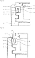
- the figure 2 illustrates the first seal 9 arranged in the first housing 17 of the cover 5, with its connecting part 12 oriented upwards and its annular lip 13 oriented downwards, that is to say towards the working accessory 4.
- the inner wall 11 is disposed in the bottom of the first housing 17 of the cover.
- the figure 3 illustrates the first seal 9 arranged in the first housing 17 of the cover 5, with its connecting part 12 oriented downwards, that is to say the working accessory 4, and its annular lip 13 oriented upwards, that is to say towards the cover 5.
- the inner wall 11 is disposed in the bottom of the first housing 17 of the cover.
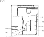
- the figure 4 illustrates the second seal 10 arranged in the second housing 16 of the cover 5, with its connecting part 12 oriented upwards and its annular lip 13 oriented downwards, that is to say towards the working accessory 4.
- the inner wall 11 is disposed in the bottom of the second housing 16 of the drive shaft 7.
- the figure 5 illustrates the second seal 10 arranged in the second housing 16 of the drive shaft 7, with its connecting part 12 oriented downwards, that is to say the working accessory 4 and its annular lip 13 oriented upwards, that is to say towards the cover 5.
- the inner wall 11 is arranged in the bottom of the second housing 16 of the drive shaft 7 of the cover 5.
- the figure 6 illustrates the second seal 10 arranged in the second housing 16 of the drive shaft 7, with its connecting part 12 oriented downwards, that is to say the working accessory 4, and its annular lip 13 oriented upwards, that is to say towards the cover 5.
- the inner part 11 is disposed in the bottom of the second housing 17 of the cover.
- the figure 7 illustrates the second seal 10 arranged in the second housing 16 of the drive shaft 7, with its connecting part 12 oriented upwards, that is to say towards the cover 5, and its annular lip 13 oriented towards down, that is to say towards the working accessory 4.
- the inner part 11 is disposed in the bottom of the second housing 17 of the cover.
- the figure 8 illustrates the cover 5 with the first and second seals 9, 10 arranged with their connecting parts 12 facing upwards, that is to say towards the cover 5, and their annular lips 13 facing downwards, that is to say that is to say towards the work accessory 4.
- the figure 9 illustrates the first seal 9 arranged in the first housing 17 of the cover 5, with its connecting part 12 facing downwards, that is to say towards the working accessory 4, and its annular lip 13 facing upwards , that is to say towards the cover 5.
- the second seal 10 is arranged in the second housing 16 of the drive shaft 7, with its connecting part 12 facing upwards, that is to say say towards the cover 5, and its annular lip 13 oriented downwards, that is to say towards the working accessory 4.
- the figure 10 illustrates the cover 5 with the first and second seals 9, 10 arranged with their connecting parts 12 facing downwards, that is to say towards the working accessory 4, and their annular lips 13 facing upwards, i.e. cover 5.
- the figure 11 illustrates the first seal 9 arranged in the first housing 17 of the cover 5, with its connecting part 12 oriented upwards, that is to say towards the cover 5, and its annular lip 13 oriented downwards, c ' that is to say, the working accessory 4.
- the figure 12 illustrates the cover 5 with the first seal 9, the connecting part 12 of which is oriented downwards and having a bayonet closing device 15.
- the figure 13 illustrates the cover 5 with the first seal 9, the connecting part 12 of which faces upwards and having a bayonet closing device 15.
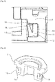
- the figure 14 illustrates the first seal 9.
- the figure 15 illustrates the second joint 10 with its angle ⁇ of displacement.
- the figure 16 illustrates the first joint 10 with its angle ⁇ of displacement.
Landscapes
- Engineering & Computer Science (AREA)
- Food Science & Technology (AREA)
- Mechanical Engineering (AREA)
- Food-Manufacturing Devices (AREA)
- Glass Compositions (AREA)
- Seal Device For Vehicle (AREA)
- Package Closures (AREA)
Abstract
Description
- La présente invention se rapporte au domaine culinaire et notamment à celui des appareils culinaires comprenant un dispositif d'entrainement à corde à commande manuelle et un bol formant un récipient, tels que des hachoirs, des presse-purée, des extracteurs de jus, des essoreuses à salade ou des mélangeurs. Ces appareils sont actionnés manuellement, et sont donc non électriques, permettant de transmettre un mouvement d'une pièce à une autre pièce par traction d'un câble ou d'une corde. La présente invention se rapporte plus particulièrement aux appareils du type précité comportant un joint d'étanchéité entre le récipient de travail et la partie supérieure de l'appareil.
- On notera que, dans ce document, les termes «longitudinal», «transversal», «perpendiculaire», «parallèle», «rotation», «horizontal», «vertical», «inférieur», «supérieur», «haut», «bas», «sécant», «coaxiaux», «convexe», «concave», «plan» employés pour décrire le dispositif, font référence à ce dispositif en situation d'usage, lorsqu'il est posé sur un plan horizontal.
- Il est connu des appareils culinaires avec des joints toriques en matière souple comme le silicone montés sur un couvercle, qui réduisent l'espace entre le couvercle et son bol, permettant une étanchéité relative aux liquides.
- L'inconvénient de ces joints toriques est leur faible variation dimensionnelle, provoquant un moindre degré de liberté et de compressibilité. En effet, pour assurer une étanchéité entre 2 parois, il convient qu'un joint puisse s'insérer dans l'espace entre ces 2 parois et combler cet espace afin de garantir une étanchéité. Or, la capacité de compression des joints toriques est faible ce qui a pour conséquence de limiter leur capacité à s'adapter et à combler l'espace.
- De plus, certains hachoirs manuels possèdent un dispositif de fermeture par baïonnettes. Pour réaliser la fermeture avec de tels dispositifs à baïonnettes, le couvercle doit être placé au-dessus du bol et doit entrer en rotation pour atteindre la position fermée et vis-versa pour la position ouverte. La capacité d'un joint torique à permettre cette rotation du couvercle pour un enclenchement par baïonnette est limitée à cause de la friction du joint contre le bol. En effet, la force de friction nécessaire pour enclencher le couvercle sur le bol, par un dispositif à baïonnette, est trop importante et n'est pas acceptable pour une ouverture aisée par un utilisateur. La faible variation dimensionnelle des joints toriques ne permet pas de diminuer cette friction et à tendance à provoquer un blocage en rotation, d'autant plus que le joint torique est dimensionné pour le jeu maximum garantissant l'étanchéité. L'inconvénient des joints toriques est de n'accepter qu'une faible plage de tolérance de variation dimensionnelle, ce qui n'est pas compatible avec les tolérances nécessaires lorsque les pièces sont obtenues avec les méthodes d'injections plastiques.
- De plus, les appareils de préparation culinaire à entrainement manuel comprennent un bol pour contenir les aliments à traiter, un accessoire de travail rotatif amovible disposé dans le bol, qui est généralement un système d'entrainement en rotation de couteaux, un couvercle amovible fermant le bol comprenant un moteur à commande manuelle pour entrainer en rotation un arbre d'entraînement et l'accessoire de travail rotatif autour d'un axe de rotation par traction d'une corde transversalement à l'axe de rotation. Le moteur à commande manuelle comprend généralement une roue d'entrainement, un ressort de rappel et une corde dont une extrémité est enroulée autour de la roue d'entrainement et dont l'autre extrémité est reliée à une poignée.
- Pour que la rotation des couteaux ou lames de découpage puisse se faire correctement, il est souvent nécessaire de prévoir un jeu entre la partie rotative et la partie fixe pour une rotation libre sans friction.
- Par le terme « jeu », il est généralement entendu au sens de l'invention une aisance de mouvement d'un élément due à un espace entre deux pièces ou deux surfaces. Là encore, les mêmes problèmes se posent avec les joints toriques, souvent utilisés pour éliminer ce jeu entre les pièces, à cause de leur faible variation dimensionnelle, provoquant un moindre degré de liberté et de compressibilité.
- Aussi minime que puisse être le jeu, il y a souvent la possibilité pour une préparation alimentaire semi-liquide à liquide de remonter le long de l'entraineur (système d'entrainement de couteaux en rotation) et de passer dans la zone intérieure du couvercle où le mécanisme d'actionnement manuel est présent. Il est impossible de nettoyer correctement cette zone sans démonter le couvercle, qui souvent n'est pas conçu pour être démontable. Le joint torique ne pouvant pas s'adapter à l'espace à combler, celui-ci étant d'autant plus important et variable lorsque les pièces sont issues d'un procédé d'injection plastique, l'étanchéité du hachoir n'est pas assurée.
- Le but de l'invention est donc de remédier aux inconvénients précités et de fournir un hachoir manuel avec une étanchéité parfaite au niveau des jeux entre le couvercle et le bol, et entre le couvercle et l'arbre d'entrainement, sans gêner la rotation du couvercle ou de l'arbre d'entrainement. Ainsi le problème résolu par l'invention est de réaliser une étanchéité tout en maintenant la mobilité, notamment en rotation, des pièces du couvercle. Ainsi une étanchéité parfaite du hachoir au niveau du couvercle et du bol permet à un utilisateur de préparer des préparations alimentaires liquides dans le bol et de mélanger cette préparation alimentaire en secouant le hachoir.
- De manière inattendue, les inventeurs ont mis en évidence qu'il est possible d'utiliser des joints avec une lèvre annulaire mobile et déformable pour permettre d'offrir une étanchéité du hachoir tout en gardant la nécessité de la libre rotation du couvercle et de l'arbre d'entrainement.
- Le hachoir selon l'invention présente l'avantage que le joint à lèvre annulaire permet une rotation du couvercle sans effort pour pivoter le couvercle sur le bol et atteindre la position fermée ou vice-versa la position ouverte par un dispositif de fermeture à baïonnette. La surface de contact de la lèvre annulaire du joint avec la partie fixe du bol étant très mince, les frictions sont très faibles. De plus, la flexion de la lèvre annulaire lui permet d'opérer une faible résistance et de ne pas résister ou bloquer le couvercle lors de sa rotation, autorisant ainsi une libre rotation de la partie rotative, suffisante pour faire une barrière étanche à la préparation semi-liquide à liquide.
- De plus le hachoir selon l'invention présente l'avantage de proposer une seule géométrie du joint, mais deux localisations sur le couvercle pour garantir son étanchéité. La même géométrie de joint est utilisée pour le logement du couvercle et le logement de l'arbre d'entrainement.
- Un autre avantage de l'invention est que le joint peut s'adapter aux variations dimensionnelles dans l'espace dans lequel il est introduit, c'est-à-dire le logement du joint.
- Un autre avantage de l'invention est que le hachoir peut être agité manuellement par un utilisateur afin de secouer la préparation alimentaire semi-liquide ou liquide pour mélanger les préparations, sans projection en dehors de l'appareil et sans projection à l'intérieur du couvercle où réside le mécanisme d'entrainement.
- Un autre avantage de l'invention est que le joint peut coopérer avec le couvercle. En effet sa nature souple et sa conception structurelle lui permettent de se compresser, ni trop, ni trop peu, pour compenser le jeu réel entre le couvercle et le bol, et le couvercle et l'arbre d'entrainement.
- La présente invention a pour objet un appareil de préparation culinaire à entrainement manuel comportant
un bol pour contenir les aliments à traiter avec une face latérale,
un accessoire de travail rotatif amovible disposé dans le bol,
un couvercle amovible disposé sur le bol,
le couvercle comprenant un moteur à commande manuelle pour entrainer en rotation un arbre d'entraînement de l'accessoire de travail rotatif autour d'un axe A de rotation par traction d'une corde transversalement à l'axe A de rotation,
caractérisé en ce que le couvercle comprend
un premier joint d'étanchéité dynamique disposé entre le couvercle et la face latéral du bol afin de combler l'espace entre le couvercle et le bol;
un second joint d'étanchéité dynamique, disposé entre le couvercle et l'arbre d'entrainement afin de combler l'espace entre l'arbre d'entraînement et le couvercle ;
chaque joint présente une paroi intérieure, une partie de liaison agencée sur le couvercle, une lèvre annulaire et une gorge;
la lèvre annulaire étant mobile et déformable avec un angle α de débattement s'étendant vers l'extérieur par rapport à l'axe A de rotation, de manière à assurer l'étanchéité lorsque le couvercle est relié au bol en position de travail. Le premier joint d'étanchéité est dynamique dans son usage car il présente une mobilité relative par rapport au bol mais reste solidaire du couvercle. Le second joint d'étanchéité est dynamique dans son usage car il présente une mobilité relative par rapport au couvercle mais reste solidaire de l'arbre d'entrainement, contrairement aux joints statiques. La partie de liaison agit comme une articulation qui permet un débattement angulaire de la lèvre. - Selon une autre caractéristique de l'appareil selon l'invention, les premier et second joints d'étanchéité dynamiques peuvent être annulaires. Ces joints d'étanchéité dynamiques annulaires peuvent se présenter sous la forme d'une bague circulaire ou rectangulaire.
- Selon une autre caractéristique de l'invention, ces joints d'étanchéité dynamiques peuvent être idéalement fabriqués dans une matière souple comme par exemple le silicone ou un thermoplastique élastomère.
- Selon une autre caractéristique de l'appareil selon l'invention, la partie de liaison du premier ou du second joint peut être en position basse permettant une insertion facilitée du couvercle sur le bol. Ainsi le premier joint présente une partie de liaison dirigée de préférence vers l'unité de travail, permettant une insertion facilitée du couvercle lors de son accostage sur le bol. Le second joint permet une insertion facilitée de l'arbre d'entrainement dans sa coopération avec l'alésage du couvercle. Dans ces 2 cas, l'insertion est facilitée car la position basse de la partie de liaison positionne la lèvre annulaire comme un cône d'insertion qui facilite sa mise en place. L'agencement de la lèvre annulaire la fera glisser sur la face latérale du bol lors de son mouvement de fermeture de l'appareil culinaire, grâce la disposition inclinée de la lèvre en forme de biseau.
- Selon une autre caractéristique de l'appareil selon l'invention, la partie de liaison du premier ou du second joint est en position haute. Ainsi le premier ou le second joint présente une partie de liaison dirigée de préférence vers le couvercle.
- Avantageusement, cet agencement permet de garantir une étanchéité maximum de l'appareil culinaire. En effet, dans cette position le liquide ou semi liquide ayant soit tendance à remonter le long de l'arbre d'entrainement ou le long du bol, soit tendance à être projeté par l'unité de travail, remplira la gorge du joint et exercera une pression contre la paroi intérieure fixe et la lèvre annulaire. Celle-ci étant capable de se déformer, se plaquera contre la face latérale du bol pour le premier joint et contre l'alésage du couvercle pour le second joint, assurant ainsi une étanchéité maximum.
- Selon une autre caractéristique de l'appareil selon l'invention, la lèvre annulaire du second joint peut être inclinée de manière à laisser la libre rotation de l'arbre d'entrainement. Ainsi la force de frottement ou de friction de la lèvre annulaire du second joint contre l'alésage n'empêche pas le mouvement de la corde lors de son tirage ou son retour. De préférence, la force de frottement de la lèvre annulaire du second joint est inférieure à la force de rappel du ressort. Dans le cas contraire, la force de frottement de la lèvre annulaire pourrait empêcher la libre rotation si cette force était trop importante, et venir bloquer le mouvement de l'arbre d'entrainement et le mouvement de rétractation de la corde.
- Selon une autre caractéristique de l'appareil selon l'invention, la lèvre annulaire du premier joint est inclinée de manière à laisser la libre rotation du couvercle lors de son enclenchement au bol par un dispositif de fermeture à baïonnette. Ainsi l'épaisseur et la géométrie du joint sont avantageusement dimensionnés pour assurer le meilleur compromis entre l'étanchéité et la libre rotation des pièces, sans provoquer de blocage des pièces, notamment par la force exercée par un utilisateur enclenchant ou déclenchant le dispositif de fermeture à baïonnette.
- Selon une autre caractéristique de l'appareil selon l'invention, la gorge des premier et second joints est agencée entre la paroi intérieure, la partie de liaison et la lèvre annulaire. Ainsi cet espace formé par la gorge est un espace de débattement pour permettre à la lèvre annulaire d'assurer sa fonction d'étanchéité. En effet, la gorge crée un espace qui permet le retour de la lèvre annulaire vers la paroi intérieure du joint sans la déformer, la partie de liaison jouant le rôle d'une articulation et la lèvre annulaire fléchissant depuis cette articulation vers la gorge.
- Selon une autre caractéristique de l'appareil selon l'invention, la largeur de la section de la paroi intérieure présente une largeur x qui est au moins égale à la largeur de la section de la lèvre annulaire. Ainsi la section de la paroi intérieure présente une largeur x supérieure à celle de la largeur de la section de la lèvre annulaire, ce qui généralement détermine la souplesse de la lèvre. Cette souplesse est relative par rapport à celle de la paroi intérieure. Cela permet d'assurer la mobilité de la lèvre annulaire sans que la paroi intérieure ne se décolle ou se soulève de son logement ; en conservant la géométrie du joint quelle que soit la déformation de la lèvre annulaire. La lèvre reste mobile dans l'intégralité de son angle α de débattement sans provoquer la déformation de la paroi intérieure du joint.
- Avantageusement le premier joint est agencé dans un premier logement qui peut être une nervure ou une encoche du couvercle. Le premier logement est un espace coopérant avec le joint afin de le recevoir. La géométrie du logement est adaptée à celle du joint afin qu'il puisse coopérer et s'y insérer. Ainsi, le premier logement permet de positionner aisément et d'orienter le joint par rapport au bol.
- Avantageusement le second joint est agencé dans un second logement qui peut être une nervure ou une encoche de l'arbre d'entrainement. Le second logement est un espace coopérant avec le joint afin de le recevoir. La géométrie du logement est adaptée à celle du joint afin qu'il puisse coopérer et s'y insérer. Ainsi, le second logement permet de positionner aisément et d'orienter le joint par rapport au couvercle.
- Selon une autre caractéristique de l'appareil selon l'invention, l'angle α de débattement est compris de 0° à 90°, de préférence de 0° à 45°. Ainsi l'angle α de débattement permet de compenser les variations dimensionnelles de l'espace résiduel entre l'alésage du couvercle et l'arbre d'entrainement et, entre le couvercle et le bol.
- La lèvre annulaire du premier joint présente son angle α maximum de débattement lorsque le couvercle est détaché de l'appareil, c'est-à-dire en position de repos. La lèvre annulaire du premier joint présente son angle α minimum de débattement lorsque le couvercle est relié au bol en position de travail.
- La lèvre annulaire du second joint présente son angle α maximum de débattement lorsque l'arbre d'entrainement est démonté du couvercle et sorti de l'alésage du couvercle. La lèvre annulaire du second joint présente son angle α minimum de débattement lorsque l'arbre d'entrainement est monté sur le couvercle.
- Selon une autre caractéristique de l'appareil selon l'invention, le premier joint est amovible et agencé élastiquement dans un premier logement du couvercle. Ainsi le montage et démontage des joints sera facilité et cela aura pour conséquence de faciliter le nettoyage. En effet, les joints étant amovibles pour pouvoir être nettoyés plus facilement, il sera possible de les repositionner aisément.
- Selon une autre caractéristique de l'appareil selon l'invention, le second joint est amovible et agencé élastiquement au niveau d'un second logement de l'arbre d'entraînement. Ainsi la facilité de démontage, de nettoyage et de remontage est équivalente à celle du premier joint.
- Selon une autre caractéristique de l'appareil selon l'invention, la paroi intérieure du premier et du second joint est agencée en vis-à-vis de la lèvre annulaire. Ainsi la lèvre et la paroi intérieure sont agencées en face à face, et forment un espace de déformation, appelé la gorge, déterminant la pression ressort suivant l'angle α de débattement.
- Selon une variante de l'appareil selon l'invention, la paroi intérieure peut être agencée transversalement par rapport à la lèvre annulaire mobile. Ainsi l'espace de débattement, qui permet à la lèvre d'assurer sa fonction d'étanchéité est conservé.
- Selon une autre caractéristique de l'appareil selon l'invention, chaque joint présente une section en U ou en V.
- Selon une autre caractéristique, l'appareil selon l'invention peut être un hachoir, un extracteur de jus ou un mélangeur.
- On comprendra mieux les buts, aspects et avantages de la présente invention, d'après la description donnée ci-après de modes particuliers de réalisation de l'invention présentés à titre d'exemples non limitatifs, en se référant aux dessins annexés dans lesquels :
- [
Fig. 1 ] lafigure 1 est une vue en coupe d'un appareil de préparation culinaire selon l'invention, de type hachoir, comprenant un premier et un second joints d'étanchéité dynamiques. Le hachoir est agencé dans sa phase de travail selon un mode particulier de réalisation de l'invention. - [
Fig. 2 ] lafigure 2 est une vue en coupe d'un premier joint avec sa partie de liaison en position haute selon un mode particulier de réalisation d'un hachoir selon l'invention. - [
Fig. 3 ] lafigure 3 est une vue coupe d'un premier joint avec sa partie de liaison en position basse selon un mode particulier de réalisation d'un hachoir selon l'invention. - [
Fig. 4 ] lafigure 4 est une vue en coupe d'un second joint avec sa partie de liaison en position haute selon un mode particulier de réalisation d'un hachoir selon l'invention. - [
Fig. 5 ] lafigure 5 est une vue en coupe d'un second joint avec sa partie de liaison en position basse selon un mode particulier de réalisation d'un hachoir selon l'invention. - [
Fig. 6 ] lafigure 6 est une vue en perspective d'un second joint avec sa partie de liaison en position basse agencée sur l'arbre d'entrainement du moteur à commande manuelle selon un mode particulier de réalisation d'un hachoir selon l'invention. - [
Fig. 7 ] lafigure 7 est une vue en perspective d'un second joint avec sa partie de liaison en position haute agencée sur l'arbre d'entrainement du moteur à commande manuelle selon un mode particulier de réalisation d'un hachoir selon l'invention. - [
Fig. 8 ] lafigure 8 est une vue en perspective d'un couvercle d'un hachoir selon l'invention selon un mode particulier de réalisation présentant un premier joint avec sa partie de liaison en position haute et un second joint avec sa partie de liaison en position haute agencée sur l'arbre d'entrainement du moteur à commande manuelle. - [
Fig. 9 ] lafigure 9 est une vue en perspective d'un couvercle d'un hachoir selon l'invention selon un mode particulier de réalisation présentant un premier joint avec sa partie de liaison en position basse et un second joint avec sa partie de liaison en position haute agencée sur l'arbre d'entrainement du moteur à commande manuelle. - [
Fig. 10 ] lafigure 10 est une vue en perspective d'un couvercle d'un hachoir selon l'invention selon un mode particulier de réalisation présentant un premier joint avec sa partie de liaison en position basse et un second joint avec sa partie de liaison en position basse agencée sur l'arbre d'entrainement du moteur à commande manuelle. - [
Fig. 11 ] lafigure 11 est une vue en perspective d'un couvercle d'un hachoir selon l'invention selon un mode particulier de réalisation présentant un premier joint avec sa partie de liaison en position haute et un second joint avec sa partie de liaison en position basse agencée sur l'arbre d'entrainement du moteur à commande manuelle. - [
Fig. 12 ] lafigure 12 est une vue en perspective d'un couvercle d'un hachoir selon l'invention selon un mode particulier de réalisation présentant un premier joint avec sa partie de liaison en position basse. - [
Fig. 13 ] lafigure 13 est une vue en perspective d'un couvercle d'un hachoir selon l'invention selon un mode particulier de réalisation présentant un premier joint avec sa partie de liaison en position haute. - [
Fig. 14 ] lafigure 14 est une vue en coupe d'un premier joint d'un hachoir selon l'invention selon un mode particulier de réalisation. - [
Fig. 15 ] lafigure 15 est une vue en coupe d'un second joint d'un hachoir selon l'invention selon un mode particulier de réalisation. - [
Fig. 16 ] lafigure 16 est une vue en coupe d'un premier joint d'un hachoir selon l'invention selon un mode particulier de réalisation. - La
figure 1 illustre un exemple d'appareil selon l'invention. Il s'agit d'un hachoir 1 à entrainement manuel comportant un bol 2 pour contenir les aliments à découper avec une face 3 latérale, un accessoire 4 de coupe rotatif amovible disposé dans le bol 2, un couvercle 5 amovible disposé sur le bol 2. Le couvercle 5 comprend un moteur 6 à commande manuelle pour entrainer en rotation un arbre 7 d'entraînement de l'accessoire 4 de coupe rotatif autour d'un axe A de rotation par traction d'une corde 8 transversalement à l'axe A de rotation. Le moteur 6 à commande manuelle comprend une roue d'entrainement, un ressort de rappel (visible sur lesfigures 8 ,9 ,10 et11 ) et une corde 8 dont une extrémité est enroulée autour de la roue d'entrainement et dont l'autre extrémité est reliée à une poignée. - Le mouvement de rotation est transmis par l'arbre 7 d'entrainement du moteur à l'unité de travail via un accouplement 19. Le couvercle 5 comprend un premier joint 9 d'étanchéité dynamique disposé entre le couvercle 5 et la face 3 latérale du bol 2 afin de combler l'espace entre le couvercle 5 et le bol 2. Le couvercle 5 comprend un second joint 10 d'étanchéité dynamique, disposé entre le couvercle 5 et l'arbre 7 d'entrainement afin de combler l'espace entre l'arbre 7 d'entraînement et l'alésage 18 du couvercle 5 ; chaque joint 9 ; 10 présente une paroi 11 intérieure, une partie de liaison 12 agencée sur le couvercle 5, une lèvre 13 annulaire et une gorge 14. La lèvre 13 annulaire est mobile et déformable avec un angle α de débattement (visible sur les
figures 15 et 16 ) s'étendant vers l'extérieur par rapport à l'axe A de rotation, de manière à assurer l'étanchéité lorsque le couvercle 5 est relié au bol 2 en position de travail. - Le fonctionnement du hachoir illustré à la
figure 1 est le suivant. Un utilisateur se saisit du couvercle 5 et met en place le premier joint 9, après l'avoir nettoyé, dans son logement 17 qui est une rainure agencée sur le pourtour du couvercle 5. Comme illustré à lafigure 1 l'utilisateur positionne la partie de liaison 12 vers le haut en direction de la partie supérieure du couvercle 5. Puis l'utilisateur se saisit du second joint 10, après l'avoir nettoyé, et le place dans son logement 16 qui est une rainure agencée sur le pourtour de l'arbre 7 d'entrainement. Après réassemblage de l'arbre 7 d'entrainement dans l'alésage 18 du couvercle 5 et fermeture de l'ensemble, le couvercle 5 ainsi muni de ses 2 joints est amené vers le bol 2 afin de procéder à l'accostage du couvercle 5. L'utilisateur positionne les ergots du bol en vis-à-vis des baïonnettes 15 du couvercle (visibles sur lafigure 9 ). - La
figure 2 illustre le premier joint 9 agencé dans le premier logement 17 du couvercle 5, avec sa partie de liaison 12 orientée vers le haut et sa lèvre 13 annulaire orientée vers le bas, c'est-à-dire vers l'accessoire 4 de travail. La paroi 11 intérieure est disposée dans le fond du premier logement 17 du couvercle. - La
figure 3 illustre le premier joint 9 agencé dans le premier logement 17 du couvercle 5, avec sa partie de liaison 12 orientée vers le bas, c'est-à-dire l'accessoire 4 de travail, et sa lèvre 13 annulaire orientée vers le haut, c'est-à-dire vers le couvercle 5. La paroi 11 intérieure est disposée dans le fond du premier logement 17 du couvercle. - La
figure 4 illustre le second joint 10 agencé dans le second logement 16 du couvercle 5, avec sa partie de liaison 12 orientée vers le haut et sa lèvre 13 annulaire orientée vers le bas, c'est-à-dire vers l'accessoire 4 de travail. La paroi 11 intérieure est disposée dans le fond du second logement 16 de l'arbre 7 d'entrainement. - La
figure 5 illustre le second joint 10 agencé dans le second logement 16 de l'arbre 7 d'entrainement, avec sa partie de liaison 12 orientée vers le bas, c'est-à-dire l'accessoire 4 de travail et sa lèvre 13 annulaire orientée vers le haut, c'est-à-dire vers le couvercle 5. La paroi 11 intérieure est disposée dans le fond du second logement 16 de l'arbre 7 d'entrainement du couvercle 5. - La
figure 6 illustre le second joint 10 agencé dans le second logement 16 de l'arbre 7 d'entrainement, avec sa partie de liaison 12 orientée vers le bas, c'est-à-dire l'accessoire 4 de travail, et sa lèvre 13 annulaire orientée vers le haut, c'est-à-dire vers le couvercle 5. La partie 11 intérieure est disposée dans le fond du second logement 17 du couvercle. - La
figure 7 illustre le second joint 10 agencé dans le second logement 16 de l'arbre 7 d'entrainement, avec sa partie de liaison 12 orientée vers le haut, c'est-à-dire vers le couvercle 5, et sa lèvre 13 annulaire orientée vers le bas, c'est-à-dire vers l'accessoire 4 de travail. La partie 11 intérieure est disposée dans le fond du second logement 17 du couvercle. - La
figure 8 illustre le couvercle 5 avec les premier et second joints 9, 10 agencés avec leurs parties de liaison 12 orientées vers le haut, c'est-à-dire vers le couvercle 5, et leurs lèvres 13 annulaires orientées vers le bas, c'est-à-dire vers l'accessoire 4 de travail. - La
figure 9 illustre le premier joint 9 agencé dans le premier logement 17 du couvercle 5, avec sa partie de liaison 12 orientée vers le bas, c'est-à-dire vers l'accessoire 4 de travail, et sa lèvre 13 annulaire orientée vers le haut, c'est-à-dire vers le couvercle 5. Le second joint 10 est agencé dans le second logement 16 de l'arbre 7 d'entrainement, avec sa partie de liaison 12 orientée vers le haut, c'est-à-dire vers le couvercle 5, et sa lèvre 13 annulaire orientée vers le bas, c'est-à-dire vers l'accessoire 4 de travail. - La
figure 10 illustre le couvercle 5 avec les premier et second joints 9, 10 agencés avec leurs parties de liaison 12 orientées vers le bas, c'est-à-dire vers l'accessoire 4 de travail, et leurs lèvres 13 annulaires orientées vers le haut, c'est-à-dire le couvercle 5. - La
figure 11 illustre le premier joint 9 agencé dans le premier logement 17 du couvercle 5, avec sa partie de liaison 12 orientée vers le haut, c'est-à-dire vers le couvercle 5, et sa lèvre 13 annulaire orientée vers le bas, c'est-à-dire l'accessoire 4 de travail. Le second joint 10 agencé dans le second logement 16 de l'arbre 7 d'entrainement logé dans l'alésage 18 du couvercle 5, avec sa partie de liaison 12 orientée vers le bas, c'est-à-dire vers l'accessoire 4 de travail, et sa lèvre 13 annulaire orientée vers le haut, c'est-à-dire vers le couvercle 5. - La
figure 12 illustre le couvercle 5 avec le premier joint 9 dont la partie de liaison 12 est orientée vers le bas et présentant un dispositif 15 de fermeture à baïonnette. - La
figure 13 illustre le couvercle 5 avec le premier 9 joint dont la partie de liaison 12 est orientée vers le haut et présentant un dispositif 15 de fermeture à baïonnette. - La
figure 14 illustre le premier joint 9. - La
figure 15 illustre le second joint 10 avec son angle α de débattement. - La
figure 16 illustre le premier joint 10 avec son angle α de débattement.
Claims (15)
- Appareil (1) de préparation culinaire à entrainement manuel comportant
un bol (2) pour contenir les aliments à traiter avec une face (3) latérale,
un accessoire (4) de travail rotatif amovible disposé dans le bol (2),
un couvercle (5) amovible disposé sur le bol (2),
le couvercle (5) comprenant un moteur (6) à commande manuelle pour entrainer en rotation un arbre (7) d'entraînement de l'accessoire (4) de travail rotatif autour d'un axe A de rotation par traction d'une corde (8) transversalement à l'axe A de rotation,
caractérisé en ce que le couvercle (5) comprend
un premier joint (9) d'étanchéité dynamique disposé entre le couvercle (5) et la face (3) latérale du bol (2) afin de combler l'espace entre le couvercle (5) et le bol (2);
un second joint (10) d'étanchéité dynamique, disposé entre le couvercle (5) et l'arbre (7) d'entrainement afin de combler l'espace entre l'arbre (7) d'entraînement et le couvercle (5) ;
chaque joint (9 ; 10) présente une paroi (11) intérieure, une partie de liaison (12) agencée sur le couvercle (5), une lèvre (13) annulaire et une gorge (14), la lèvre (13) annulaire étant mobile et déformable avec un angle α de débattement s'étendant vers l'extérieur par rapport à l'axe A de rotation, de manière à assurer l'étanchéité lorsque le couvercle (5) est relié au bol (2) en position de travail. - Appareil (1) de préparation culinaire selon la revendication 1 caractérisé en ce que les premier et second joints (9 ; 10) d'étanchéité dynamique sont annulaires.
- Appareil (1) de préparation culinaire selon l'une des revendications précédentes caractérisé en ce que la partie de liaison (12) du premier ou du second joint (9 ; 10) est en position basse permettant une insertion facilitée du couvercle (5) sur le bol (2).
- Appareil (1) de préparation culinaire selon l'une des revendications précédentes caractérisé en ce que la partie de liaison (12) du premier ou du second joint (9 ; 10) est en position haute.
- Appareil (1) de préparation culinaire selon l'une des revendications précédentes caractérisé en ce que la lèvre (13) annulaire du second joint (10) est inclinée de manière à laisser la libre rotation de l'arbre (7) d'entrainement.
- Appareil (1) de préparation culinaire selon l'une des revendications précédentes caractérisé en ce que la lèvre (13) annulaire du premier joint (9) est inclinée de manière à laisser la libre rotation du couvercle (5) dans son enclenchement au bol (2) par un dispositif de fermeture à baïonnette (15).
- Appareil (1) de préparation culinaire selon l'une des revendications précédentes caractérisé en ce que la gorge (14) des premier et second joints (9 ; 10) est agencée entre la paroi (11) intérieure, la partie de liaison (12) et la lèvre (13) annulaire.
- Appareil (1) de préparation culinaire selon l'une des revendications précédentes caractérisé en ce que la largeur de la section de la paroi (11) intérieure présente une largeur x qui est au moins égale à la largeur de la section de la lèvre (13) annulaire.
- Appareil (1) de préparation culinaire selon l'une des revendications précédentes caractérisé en ce que l'angle α de débattement est compris de 0° à 90°, de préférence de 0° à 45°.
- Appareil (1) de préparation culinaire selon l'une des revendications précédentes caractérisé en ce que le premier joint (9) est amovible et agencé élastiquement dans un premier logement (17) du couvercle (5).
- Appareil (1) de préparation culinaire selon l'une des revendications précédentes caractérisé en ce que le second joint (10) est amovible et agencé élastiquement au niveau d'un second logement (16) de l'arbre (7) d'entraînement.
- Appareil (1) de préparation culinaire selon l'une des revendications précédentes caractérisé en ce que la paroi (11) intérieure du premier et du second joint (9, 10) est agencée en vis-à-vis de la lèvre (13) annulaire.
- Appareil (1) de préparation culinaire selon l'une des revendications précédentes caractérisé en ce que la paroi (11) intérieure est agencée transversalement par rapport à la lèvre (13) annulaire mobile.
- Appareil (1) de préparation culinaire selon l'une des revendications précédentes caractérisé en ce que chaque joint (9; 10) présente une section en U ou en V.
- Appareil (1) selon l'une des revendications précédentes caractérisé en ce qu'il est un hachoir, un extracteur de jus ou un mélangeur.
Applications Claiming Priority (1)
| Application Number | Priority Date | Filing Date | Title |
|---|---|---|---|
| FR2001214A FR3106965B1 (fr) | 2020-02-07 | 2020-02-07 | Hachoir manuel a double systeme d'etancheite |
Publications (2)
| Publication Number | Publication Date |
|---|---|
| EP3861904A1 true EP3861904A1 (fr) | 2021-08-11 |
| EP3861904B1 EP3861904B1 (fr) | 2022-10-12 |
Family
ID=70918561
Family Applications (1)
| Application Number | Title | Priority Date | Filing Date |
|---|---|---|---|
| EP21151874.1A Active EP3861904B1 (fr) | 2020-02-07 | 2021-01-15 | Hachoir manuel à double système d'étanchéité |
Country Status (7)
| Country | Link |
|---|---|
| US (1) | US11678771B2 (fr) |
| EP (1) | EP3861904B1 (fr) |
| CN (1) | CN113243781A (fr) |
| DK (1) | DK3861904T3 (fr) |
| ES (1) | ES2935721T3 (fr) |
| FR (1) | FR3106965B1 (fr) |
| PL (1) | PL3861904T3 (fr) |
Families Citing this family (2)
| Publication number | Priority date | Publication date | Assignee | Title |
|---|---|---|---|---|
| US20230255408A1 (en) * | 2022-02-17 | 2023-08-17 | Jesse Chow | Food processing apparatus as well as its container cover and its container |
| FR3133986B1 (fr) | 2022-03-30 | 2024-10-18 | Seb Sa | Appareil culinaire avec dispositif d’entrainement a corde a commande manuelle |
Citations (3)
| Publication number | Priority date | Publication date | Assignee | Title |
|---|---|---|---|---|
| EP0963726A1 (fr) * | 1998-06-10 | 1999-12-15 | Hispainox S.A. | Machine électrique domestique |
| FR2896395A1 (fr) * | 2006-01-20 | 2007-07-27 | Hameur Sa | Appareil de traitement d'aliments muni d'un dispositif d'amerioration d'un fonctionnement d'un tel appareil |
| EP3311718A1 (fr) * | 2016-10-24 | 2018-04-25 | Seb S.A. | Appareil electromenager de preparation culinaire chauffant comportant un joint annulaire |
Family Cites Families (12)
| Publication number | Priority date | Publication date | Assignee | Title |
|---|---|---|---|---|
| EP0311718A1 (fr) | 1987-10-13 | 1989-04-19 | Locwyn Limited | Dossier suspendu |
| US20020153440A1 (en) * | 2001-04-19 | 2002-10-24 | Holcomb David A. | Hand-held food processor |
| AU2002313439A1 (en) * | 2001-11-19 | 2003-06-10 | Moha Moderne Haushaltwaren Ag | Salad shaker |
| FR2862853B1 (fr) * | 2003-11-27 | 2006-09-15 | Seb Sa | Appareil de cuisson sous pression muni d'un dispositif de securite a la surpression, et joint d'etancheite pour un tel appareil |
| FR2922428A1 (fr) * | 2007-10-23 | 2009-04-24 | Seb Sa | Autocuiseur pourvu d'un systeme de securite a la surpression |
| CN201349972Y (zh) * | 2008-12-25 | 2009-11-25 | 九阳股份有限公司 | 一种豆浆机轴密封圈 |
| DE102011000219A1 (de) * | 2010-03-31 | 2011-10-06 | Vorwerk & Co. Interholding Gmbh | Elektromotorisch betriebene Küchenmaschine, sowie Zubereitungsgefäß |
| CH706727A2 (de) * | 2012-07-12 | 2014-01-15 | Swizzzcut Ag | Gerät zum Bearbeiten von Lebensmitteln. |
| FR3057750B1 (fr) * | 2016-10-24 | 2018-11-16 | Seb S.A. | Appareil electromenager de preparation culinaire chauffant presentant un conduit d’evacuation |
| FR3057749B1 (fr) * | 2016-10-24 | 2019-11-01 | Seb S.A. | Appareil electromenager de preparation culinaire chauffant comportant une securite de deverrouillage |
| FR3057752B1 (fr) * | 2016-10-24 | 2021-05-28 | Seb Sa | Appareil electromenager de preparation culinaire comportant un couvercle intermediaire |
| CN208740649U (zh) * | 2018-05-10 | 2019-04-16 | 佛山市顺德区美的电热电器制造有限公司 | 烹饪设备 |
-
2020
- 2020-02-07 FR FR2001214A patent/FR3106965B1/fr active Active
-
2021
- 2021-01-15 ES ES21151874T patent/ES2935721T3/es active Active
- 2021-01-15 DK DK21151874.1T patent/DK3861904T3/da active
- 2021-01-15 EP EP21151874.1A patent/EP3861904B1/fr active Active
- 2021-01-15 PL PL21151874.1T patent/PL3861904T3/pl unknown
- 2021-01-27 CN CN202110111264.4A patent/CN113243781A/zh active Pending
- 2021-01-29 US US17/162,493 patent/US11678771B2/en active Active
Patent Citations (3)
| Publication number | Priority date | Publication date | Assignee | Title |
|---|---|---|---|---|
| EP0963726A1 (fr) * | 1998-06-10 | 1999-12-15 | Hispainox S.A. | Machine électrique domestique |
| FR2896395A1 (fr) * | 2006-01-20 | 2007-07-27 | Hameur Sa | Appareil de traitement d'aliments muni d'un dispositif d'amerioration d'un fonctionnement d'un tel appareil |
| EP3311718A1 (fr) * | 2016-10-24 | 2018-04-25 | Seb S.A. | Appareil electromenager de preparation culinaire chauffant comportant un joint annulaire |
Also Published As
| Publication number | Publication date |
|---|---|
| DK3861904T3 (da) | 2023-01-16 |
| FR3106965B1 (fr) | 2022-01-07 |
| CN113243781A (zh) | 2021-08-13 |
| FR3106965A1 (fr) | 2021-08-13 |
| US11678771B2 (en) | 2023-06-20 |
| US20210244236A1 (en) | 2021-08-12 |
| ES2935721T3 (es) | 2023-03-09 |
| EP3861904B1 (fr) | 2022-10-12 |
| PL3861904T3 (pl) | 2023-02-06 |
Similar Documents
| Publication | Publication Date | Title |
|---|---|---|
| EP3861904B1 (fr) | Hachoir manuel à double système d'étanchéité | |
| EP3762331B1 (fr) | Distributeur de boissons post-mélange avec récipients d'ingrédients pressurisables | |
| EP3075295A1 (fr) | Appareil electromenager de preparation culinaire comportant un couvercle muni d'une cheminee pour l'introduction d'aliments | |
| EP3761835B1 (fr) | Appareil de fabrication d'une boisson | |
| EP3542689B1 (fr) | Accessoire batteur pour un appareil électroménager de préparation culinaire, equipé de fouet(s) facilement démontable(s) | |
| WO2007042680A1 (fr) | Couvercle a usages multiples, notamment pour des liquides, notamment pour pot de peinture | |
| EP3586703A1 (fr) | Dispositif d'agitation rotatif de machine de préparation de boissons équipé d'un clapet anti-retour | |
| EP1198191B1 (fr) | Batteur-mixeur electrique a main | |
| EP0649761A1 (fr) | Dispositif de fermeture des couvercles agitateurs des boîtes de teintes sur les machines d'agitation | |
| EP2071990A1 (fr) | Récipient de travail pour appareil électroménager de préparation culinaire et appareil muni d'un tel récipient | |
| FR3029095A1 (fr) | Appareil de cuisson a air chaud | |
| FR2857342A1 (fr) | Tete de distribution de produit fluide | |
| EP3542688B1 (fr) | Accessoire batteur pour un appareil électroménager de préparation culinaire, adapté au melange de faibles quantités de préparation alimentaire | |
| EP3673777A1 (fr) | Système électroménager de préparation culinaire comportant un ensemble accessoire à renvoi d'angle, ensemble accessoire, et porte-accessoire pour un tel système électroménager de préparation culinaire | |
| EP1510363A1 (fr) | Dispositif de fermeture pour boítes de peinture avec des moyens de fixation améliorés | |
| EP3049345B1 (fr) | Couvercle pour la fermeture de boite et ensemble comprenant une boite et un couvercle du type precite | |
| FR2707187A1 (fr) | Lame de coupe, notamment applicable sur des appareils du type appareil de préparation culinaire. | |
| CH625759A5 (en) | Container with lid and hinge | |
| FR3066372A1 (fr) | Appareil de mixage et de melange pour des preparations alimentaires liquides ou pateuses, equipe d’un systeme d’encliquetage d’un porte-couteau sur une bague de verrouillage | |
| FR3041271B1 (fr) | Dispositif de connexion etanche entre deux enceintes | |
| WO2006092500A1 (fr) | Appareil electromenager de preparation culinaire de type blender comprenant un baton melangeur | |
| FR3058305B1 (fr) | Dispositif de traitement d'aliments muni d'un pied d'appui | |
| EP4056075B1 (fr) | Dispositif de présentation pour produits en vrac | |
| EP3795867B1 (fr) | Joint de centrage pour couvercle d'appareil culinaire | |
| FR2559337A3 (fr) | Dispositif de mise en marche et verrouillage simultanes d'un appareil motorise tel que robot de cuisine |
Legal Events
| Date | Code | Title | Description |
|---|---|---|---|
| PUAI | Public reference made under article 153(3) epc to a published international application that has entered the european phase |
Free format text: ORIGINAL CODE: 0009012 |
|
| STAA | Information on the status of an ep patent application or granted ep patent |
Free format text: STATUS: THE APPLICATION HAS BEEN PUBLISHED |
|
| AK | Designated contracting states |
Kind code of ref document: A1 Designated state(s): AL AT BE BG CH CY CZ DE DK EE ES FI FR GB GR HR HU IE IS IT LI LT LU LV MC MK MT NL NO PL PT RO RS SE SI SK SM TR |
|
| STAA | Information on the status of an ep patent application or granted ep patent |
Free format text: STATUS: REQUEST FOR EXAMINATION WAS MADE |
|
| 17P | Request for examination filed |
Effective date: 20211209 |
|
| RBV | Designated contracting states (corrected) |
Designated state(s): AL AT BE BG CH CY CZ DE DK EE ES FI FR GB GR HR HU IE IS IT LI LT LU LV MC MK MT NL NO PL PT RO RS SE SI SK SM TR |
|
| GRAP | Despatch of communication of intention to grant a patent |
Free format text: ORIGINAL CODE: EPIDOSNIGR1 |
|
| STAA | Information on the status of an ep patent application or granted ep patent |
Free format text: STATUS: GRANT OF PATENT IS INTENDED |
|
| INTG | Intention to grant announced |
Effective date: 20220517 |
|
| GRAS | Grant fee paid |
Free format text: ORIGINAL CODE: EPIDOSNIGR3 |
|
| GRAA | (expected) grant |
Free format text: ORIGINAL CODE: 0009210 |
|
| STAA | Information on the status of an ep patent application or granted ep patent |
Free format text: STATUS: THE PATENT HAS BEEN GRANTED |
|
| AK | Designated contracting states |
Kind code of ref document: B1 Designated state(s): AL AT BE BG CH CY CZ DE DK EE ES FI FR GB GR HR HU IE IS IT LI LT LU LV MC MK MT NL NO PL PT RO RS SE SI SK SM TR |
|
| REG | Reference to a national code |
Ref country code: GB Ref legal event code: FG4D Free format text: NOT ENGLISH |
|
| REG | Reference to a national code |
Ref country code: CH Ref legal event code: EP |
|
| REG | Reference to a national code |
Ref country code: DE Ref legal event code: R096 Ref document number: 602021000520 Country of ref document: DE |
|
| REG | Reference to a national code |
Ref country code: IE Ref legal event code: FG4D Free format text: LANGUAGE OF EP DOCUMENT: FRENCH |
|
| REG | Reference to a national code |
Ref country code: AT Ref legal event code: REF Ref document number: 1523635 Country of ref document: AT Kind code of ref document: T Effective date: 20221115 |
|
| REG | Reference to a national code |
Ref country code: DK Ref legal event code: T3 Effective date: 20230110 |
|
| REG | Reference to a national code |
Ref country code: NL Ref legal event code: FP |
|
| REG | Reference to a national code |
Ref country code: SE Ref legal event code: TRGR |
|
| REG | Reference to a national code |
Ref country code: LT Ref legal event code: MG9D |
|
| REG | Reference to a national code |
Ref country code: ES Ref legal event code: FG2A Ref document number: 2935721 Country of ref document: ES Kind code of ref document: T3 Effective date: 20230309 |
|
| REG | Reference to a national code |
Ref country code: AT Ref legal event code: MK05 Ref document number: 1523635 Country of ref document: AT Kind code of ref document: T Effective date: 20221012 |
|
| PG25 | Lapsed in a contracting state [announced via postgrant information from national office to epo] |
Ref country code: PT Free format text: LAPSE BECAUSE OF FAILURE TO SUBMIT A TRANSLATION OF THE DESCRIPTION OR TO PAY THE FEE WITHIN THE PRESCRIBED TIME-LIMIT Effective date: 20230213 Ref country code: NO Free format text: LAPSE BECAUSE OF FAILURE TO SUBMIT A TRANSLATION OF THE DESCRIPTION OR TO PAY THE FEE WITHIN THE PRESCRIBED TIME-LIMIT Effective date: 20230112 Ref country code: LT Free format text: LAPSE BECAUSE OF FAILURE TO SUBMIT A TRANSLATION OF THE DESCRIPTION OR TO PAY THE FEE WITHIN THE PRESCRIBED TIME-LIMIT Effective date: 20221012 Ref country code: FI Free format text: LAPSE BECAUSE OF FAILURE TO SUBMIT A TRANSLATION OF THE DESCRIPTION OR TO PAY THE FEE WITHIN THE PRESCRIBED TIME-LIMIT Effective date: 20221012 Ref country code: AT Free format text: LAPSE BECAUSE OF FAILURE TO SUBMIT A TRANSLATION OF THE DESCRIPTION OR TO PAY THE FEE WITHIN THE PRESCRIBED TIME-LIMIT Effective date: 20221012 |
|
| PG25 | Lapsed in a contracting state [announced via postgrant information from national office to epo] |
Ref country code: RS Free format text: LAPSE BECAUSE OF FAILURE TO SUBMIT A TRANSLATION OF THE DESCRIPTION OR TO PAY THE FEE WITHIN THE PRESCRIBED TIME-LIMIT Effective date: 20221012 Ref country code: LV Free format text: LAPSE BECAUSE OF FAILURE TO SUBMIT A TRANSLATION OF THE DESCRIPTION OR TO PAY THE FEE WITHIN THE PRESCRIBED TIME-LIMIT Effective date: 20221012 Ref country code: IS Free format text: LAPSE BECAUSE OF FAILURE TO SUBMIT A TRANSLATION OF THE DESCRIPTION OR TO PAY THE FEE WITHIN THE PRESCRIBED TIME-LIMIT Effective date: 20230212 Ref country code: HR Free format text: LAPSE BECAUSE OF FAILURE TO SUBMIT A TRANSLATION OF THE DESCRIPTION OR TO PAY THE FEE WITHIN THE PRESCRIBED TIME-LIMIT Effective date: 20221012 Ref country code: GR Free format text: LAPSE BECAUSE OF FAILURE TO SUBMIT A TRANSLATION OF THE DESCRIPTION OR TO PAY THE FEE WITHIN THE PRESCRIBED TIME-LIMIT Effective date: 20230113 |
|
| REG | Reference to a national code |
Ref country code: DE Ref legal event code: R097 Ref document number: 602021000520 Country of ref document: DE |
|
| PG25 | Lapsed in a contracting state [announced via postgrant information from national office to epo] |
Ref country code: SM Free format text: LAPSE BECAUSE OF FAILURE TO SUBMIT A TRANSLATION OF THE DESCRIPTION OR TO PAY THE FEE WITHIN THE PRESCRIBED TIME-LIMIT Effective date: 20221012 Ref country code: RO Free format text: LAPSE BECAUSE OF FAILURE TO SUBMIT A TRANSLATION OF THE DESCRIPTION OR TO PAY THE FEE WITHIN THE PRESCRIBED TIME-LIMIT Effective date: 20221012 Ref country code: EE Free format text: LAPSE BECAUSE OF FAILURE TO SUBMIT A TRANSLATION OF THE DESCRIPTION OR TO PAY THE FEE WITHIN THE PRESCRIBED TIME-LIMIT Effective date: 20221012 Ref country code: CZ Free format text: LAPSE BECAUSE OF FAILURE TO SUBMIT A TRANSLATION OF THE DESCRIPTION OR TO PAY THE FEE WITHIN THE PRESCRIBED TIME-LIMIT Effective date: 20221012 |
|
| PLBE | No opposition filed within time limit |
Free format text: ORIGINAL CODE: 0009261 |
|
| STAA | Information on the status of an ep patent application or granted ep patent |
Free format text: STATUS: NO OPPOSITION FILED WITHIN TIME LIMIT |
|
| PG25 | Lapsed in a contracting state [announced via postgrant information from national office to epo] |
Ref country code: SK Free format text: LAPSE BECAUSE OF FAILURE TO SUBMIT A TRANSLATION OF THE DESCRIPTION OR TO PAY THE FEE WITHIN THE PRESCRIBED TIME-LIMIT Effective date: 20221012 Ref country code: AL Free format text: LAPSE BECAUSE OF FAILURE TO SUBMIT A TRANSLATION OF THE DESCRIPTION OR TO PAY THE FEE WITHIN THE PRESCRIBED TIME-LIMIT Effective date: 20221012 |
|
| 26N | No opposition filed |
Effective date: 20230713 |
|
| PG25 | Lapsed in a contracting state [announced via postgrant information from national office to epo] |
Ref country code: LU Free format text: LAPSE BECAUSE OF NON-PAYMENT OF DUE FEES Effective date: 20230115 |
|
| PG25 | Lapsed in a contracting state [announced via postgrant information from national office to epo] |
Ref country code: SI Free format text: LAPSE BECAUSE OF FAILURE TO SUBMIT A TRANSLATION OF THE DESCRIPTION OR TO PAY THE FEE WITHIN THE PRESCRIBED TIME-LIMIT Effective date: 20221012 |
|
| PG25 | Lapsed in a contracting state [announced via postgrant information from national office to epo] |
Ref country code: IE Free format text: LAPSE BECAUSE OF NON-PAYMENT OF DUE FEES Effective date: 20230115 |
|
| PG25 | Lapsed in a contracting state [announced via postgrant information from national office to epo] |
Ref country code: IT Free format text: LAPSE BECAUSE OF FAILURE TO SUBMIT A TRANSLATION OF THE DESCRIPTION OR TO PAY THE FEE WITHIN THE PRESCRIBED TIME-LIMIT Effective date: 20221012 |
|
| PG25 | Lapsed in a contracting state [announced via postgrant information from national office to epo] |
Ref country code: MC Free format text: LAPSE BECAUSE OF FAILURE TO SUBMIT A TRANSLATION OF THE DESCRIPTION OR TO PAY THE FEE WITHIN THE PRESCRIBED TIME-LIMIT Effective date: 20221012 |
|
| PG25 | Lapsed in a contracting state [announced via postgrant information from national office to epo] |
Ref country code: MC Free format text: LAPSE BECAUSE OF FAILURE TO SUBMIT A TRANSLATION OF THE DESCRIPTION OR TO PAY THE FEE WITHIN THE PRESCRIBED TIME-LIMIT Effective date: 20221012 |
|
| REG | Reference to a national code |
Ref country code: CH Ref legal event code: PL |
|
| PG25 | Lapsed in a contracting state [announced via postgrant information from national office to epo] |
Ref country code: CH Free format text: LAPSE BECAUSE OF NON-PAYMENT OF DUE FEES Effective date: 20240131 |
|
| PG25 | Lapsed in a contracting state [announced via postgrant information from national office to epo] |
Ref country code: CH Free format text: LAPSE BECAUSE OF NON-PAYMENT OF DUE FEES Effective date: 20240131 |
|
| PG25 | Lapsed in a contracting state [announced via postgrant information from national office to epo] |
Ref country code: BG Free format text: LAPSE BECAUSE OF FAILURE TO SUBMIT A TRANSLATION OF THE DESCRIPTION OR TO PAY THE FEE WITHIN THE PRESCRIBED TIME-LIMIT Effective date: 20221012 |
|
| PG25 | Lapsed in a contracting state [announced via postgrant information from national office to epo] |
Ref country code: BG Free format text: LAPSE BECAUSE OF FAILURE TO SUBMIT A TRANSLATION OF THE DESCRIPTION OR TO PAY THE FEE WITHIN THE PRESCRIBED TIME-LIMIT Effective date: 20221012 |
|
| PG25 | Lapsed in a contracting state [announced via postgrant information from national office to epo] |
Ref country code: CY Free format text: LAPSE BECAUSE OF FAILURE TO SUBMIT A TRANSLATION OF THE DESCRIPTION OR TO PAY THE FEE WITHIN THE PRESCRIBED TIME-LIMIT; INVALID AB INITIO Effective date: 20210115 |
|
| PG25 | Lapsed in a contracting state [announced via postgrant information from national office to epo] |
Ref country code: HU Free format text: LAPSE BECAUSE OF FAILURE TO SUBMIT A TRANSLATION OF THE DESCRIPTION OR TO PAY THE FEE WITHIN THE PRESCRIBED TIME-LIMIT; INVALID AB INITIO Effective date: 20210115 |
|
| PGFP | Annual fee paid to national office [announced via postgrant information from national office to epo] |
Ref country code: DK Payment date: 20251230 Year of fee payment: 6 |
|
| PGFP | Annual fee paid to national office [announced via postgrant information from national office to epo] |
Ref country code: NL Payment date: 20251230 Year of fee payment: 6 |
|
| PGFP | Annual fee paid to national office [announced via postgrant information from national office to epo] |
Ref country code: PL Payment date: 20251219 Year of fee payment: 6 |
|
| PGFP | Annual fee paid to national office [announced via postgrant information from national office to epo] |
Ref country code: SE Payment date: 20260127 Year of fee payment: 6 |
|
| PGFP | Annual fee paid to national office [announced via postgrant information from national office to epo] |
Ref country code: GB Payment date: 20260127 Year of fee payment: 6 |
|
| PGFP | Annual fee paid to national office [announced via postgrant information from national office to epo] |
Ref country code: ES Payment date: 20260209 Year of fee payment: 6 |
|
| PGFP | Annual fee paid to national office [announced via postgrant information from national office to epo] |
Ref country code: DE Payment date: 20260114 Year of fee payment: 6 |
|
| PGFP | Annual fee paid to national office [announced via postgrant information from national office to epo] |
Ref country code: BE Payment date: 20260119 Year of fee payment: 6 |
|
| PGFP | Annual fee paid to national office [announced via postgrant information from national office to epo] |
Ref country code: FR Payment date: 20260128 Year of fee payment: 6 |
|
| PGFP | Annual fee paid to national office [announced via postgrant information from national office to epo] |
Ref country code: TR Payment date: 20260114 Year of fee payment: 6 |