EP3861239B1 - Vorrichtungshalterung - Google Patents
Vorrichtungshalterung Download PDFInfo
- Publication number
- EP3861239B1 EP3861239B1 EP19791084.7A EP19791084A EP3861239B1 EP 3861239 B1 EP3861239 B1 EP 3861239B1 EP 19791084 A EP19791084 A EP 19791084A EP 3861239 B1 EP3861239 B1 EP 3861239B1
- Authority
- EP
- European Patent Office
- Prior art keywords
- shuttle
- mounting plate
- hinge
- coupled
- spring
- Prior art date
- Legal status (The legal status is an assumption and is not a legal conclusion. Google has not performed a legal analysis and makes no representation as to the accuracy of the status listed.)
- Active
Links
Images










Classifications
-
- G—PHYSICS
- G03—PHOTOGRAPHY; CINEMATOGRAPHY; ANALOGOUS TECHNIQUES USING WAVES OTHER THAN OPTICAL WAVES; ELECTROGRAPHY; HOLOGRAPHY
- G03B—APPARATUS OR ARRANGEMENTS FOR TAKING PHOTOGRAPHS OR FOR PROJECTING OR VIEWING THEM; APPARATUS OR ARRANGEMENTS EMPLOYING ANALOGOUS TECHNIQUES USING WAVES OTHER THAN OPTICAL WAVES; ACCESSORIES THEREFOR
- G03B17/00—Details of cameras or camera bodies; Accessories therefor
- G03B17/02—Bodies
- G03B17/04—Bodies collapsible, foldable or extensible, e.g. book type
-
- H—ELECTRICITY
- H05—ELECTRIC TECHNIQUES NOT OTHERWISE PROVIDED FOR
- H05K—PRINTED CIRCUITS; CASINGS OR CONSTRUCTIONAL DETAILS OF ELECTRIC APPARATUS; MANUFACTURE OF ASSEMBLAGES OF ELECTRICAL COMPONENTS
- H05K5/00—Casings, cabinets or drawers for electric apparatus
- H05K5/02—Details
- H05K5/0217—Mechanical details of casings
-
- F—MECHANICAL ENGINEERING; LIGHTING; HEATING; WEAPONS; BLASTING
- F16—ENGINEERING ELEMENTS AND UNITS; GENERAL MEASURES FOR PRODUCING AND MAINTAINING EFFECTIVE FUNCTIONING OF MACHINES OR INSTALLATIONS; THERMAL INSULATION IN GENERAL
- F16C—SHAFTS; FLEXIBLE SHAFTS; ELEMENTS OR CRANKSHAFT MECHANISMS; ROTARY BODIES OTHER THAN GEARING ELEMENTS; BEARINGS
- F16C11/00—Pivots; Pivotal connections
- F16C11/04—Pivotal connections
-
- F—MECHANICAL ENGINEERING; LIGHTING; HEATING; WEAPONS; BLASTING
- F16—ENGINEERING ELEMENTS AND UNITS; GENERAL MEASURES FOR PRODUCING AND MAINTAINING EFFECTIVE FUNCTIONING OF MACHINES OR INSTALLATIONS; THERMAL INSULATION IN GENERAL
- F16C—SHAFTS; FLEXIBLE SHAFTS; ELEMENTS OR CRANKSHAFT MECHANISMS; ROTARY BODIES OTHER THAN GEARING ELEMENTS; BEARINGS
- F16C11/00—Pivots; Pivotal connections
- F16C11/04—Pivotal connections
- F16C11/10—Arrangements for locking
-
- F—MECHANICAL ENGINEERING; LIGHTING; HEATING; WEAPONS; BLASTING
- F16—ENGINEERING ELEMENTS AND UNITS; GENERAL MEASURES FOR PRODUCING AND MAINTAINING EFFECTIVE FUNCTIONING OF MACHINES OR INSTALLATIONS; THERMAL INSULATION IN GENERAL
- F16M—FRAMES, CASINGS OR BEDS OF ENGINES, MACHINES OR APPARATUS, NOT SPECIFIC TO ENGINES, MACHINES OR APPARATUS PROVIDED FOR ELSEWHERE; STANDS; SUPPORTS
- F16M11/00—Stands or trestles as supports for apparatus or articles placed thereon ; Stands for scientific apparatus such as gravitational force meters
- F16M11/02—Heads
- F16M11/04—Means for attachment of apparatus; Means allowing adjustment of the apparatus relatively to the stand
- F16M11/06—Means for attachment of apparatus; Means allowing adjustment of the apparatus relatively to the stand allowing pivoting
- F16M11/10—Means for attachment of apparatus; Means allowing adjustment of the apparatus relatively to the stand allowing pivoting around a horizontal axis
- F16M11/105—Means for attachment of apparatus; Means allowing adjustment of the apparatus relatively to the stand allowing pivoting around a horizontal axis the horizontal axis being the roll axis, e.g. for creating a landscape-portrait rotation
-
- F—MECHANICAL ENGINEERING; LIGHTING; HEATING; WEAPONS; BLASTING
- F16—ENGINEERING ELEMENTS AND UNITS; GENERAL MEASURES FOR PRODUCING AND MAINTAINING EFFECTIVE FUNCTIONING OF MACHINES OR INSTALLATIONS; THERMAL INSULATION IN GENERAL
- F16M—FRAMES, CASINGS OR BEDS OF ENGINES, MACHINES OR APPARATUS, NOT SPECIFIC TO ENGINES, MACHINES OR APPARATUS PROVIDED FOR ELSEWHERE; STANDS; SUPPORTS
- F16M11/00—Stands or trestles as supports for apparatus or articles placed thereon ; Stands for scientific apparatus such as gravitational force meters
- F16M11/20—Undercarriages with or without wheels
- F16M11/22—Undercarriages with or without wheels with approximately constant height, e.g. with constant length of column or of legs
-
- F—MECHANICAL ENGINEERING; LIGHTING; HEATING; WEAPONS; BLASTING
- F16—ENGINEERING ELEMENTS AND UNITS; GENERAL MEASURES FOR PRODUCING AND MAINTAINING EFFECTIVE FUNCTIONING OF MACHINES OR INSTALLATIONS; THERMAL INSULATION IN GENERAL
- F16M—FRAMES, CASINGS OR BEDS OF ENGINES, MACHINES OR APPARATUS, NOT SPECIFIC TO ENGINES, MACHINES OR APPARATUS PROVIDED FOR ELSEWHERE; STANDS; SUPPORTS
- F16M13/00—Other supports for positioning apparatus or articles; Means for steadying hand-held apparatus or articles
-
- G—PHYSICS
- G03—PHOTOGRAPHY; CINEMATOGRAPHY; ANALOGOUS TECHNIQUES USING WAVES OTHER THAN OPTICAL WAVES; ELECTROGRAPHY; HOLOGRAPHY
- G03B—APPARATUS OR ARRANGEMENTS FOR TAKING PHOTOGRAPHS OR FOR PROJECTING OR VIEWING THEM; APPARATUS OR ARRANGEMENTS EMPLOYING ANALOGOUS TECHNIQUES USING WAVES OTHER THAN OPTICAL WAVES; ACCESSORIES THEREFOR
- G03B17/00—Details of cameras or camera bodies; Accessories therefor
- G03B17/18—Signals indicating condition of a camera member or suitability of light
- G03B17/20—Signals indicating condition of a camera member or suitability of light visible in viewfinder
-
- G—PHYSICS
- G03—PHOTOGRAPHY; CINEMATOGRAPHY; ANALOGOUS TECHNIQUES USING WAVES OTHER THAN OPTICAL WAVES; ELECTROGRAPHY; HOLOGRAPHY
- G03B—APPARATUS OR ARRANGEMENTS FOR TAKING PHOTOGRAPHS OR FOR PROJECTING OR VIEWING THEM; APPARATUS OR ARRANGEMENTS EMPLOYING ANALOGOUS TECHNIQUES USING WAVES OTHER THAN OPTICAL WAVES; ACCESSORIES THEREFOR
- G03B17/00—Details of cameras or camera bodies; Accessories therefor
- G03B17/56—Accessories
- G03B17/561—Support related camera accessories
-
- G—PHYSICS
- G06—COMPUTING OR CALCULATING; COUNTING
- G06F—ELECTRIC DIGITAL DATA PROCESSING
- G06F1/00—Details not covered by groups G06F3/00 - G06F13/00 and G06F21/00
- G06F1/16—Constructional details or arrangements
- G06F1/1601—Constructional details related to the housing of computer displays, e.g. of CRT monitors, of flat displays
-
- G—PHYSICS
- G06—COMPUTING OR CALCULATING; COUNTING
- G06F—ELECTRIC DIGITAL DATA PROCESSING
- G06F1/00—Details not covered by groups G06F3/00 - G06F13/00 and G06F21/00
- G06F1/16—Constructional details or arrangements
- G06F1/1601—Constructional details related to the housing of computer displays, e.g. of CRT monitors, of flat displays
- G06F1/1605—Multimedia displays, e.g. with integrated or attached speakers, cameras, microphones
-
- H—ELECTRICITY
- H04—ELECTRIC COMMUNICATION TECHNIQUE
- H04M—TELEPHONIC COMMUNICATION
- H04M1/00—Substation equipment, e.g. for use by subscribers
- H04M1/02—Constructional features of telephone sets
-
- H—ELECTRICITY
- H04—ELECTRIC COMMUNICATION TECHNIQUE
- H04M—TELEPHONIC COMMUNICATION
- H04M1/00—Substation equipment, e.g. for use by subscribers
- H04M1/02—Constructional features of telephone sets
- H04M1/04—Supports for telephone transmitters or receivers
-
- H—ELECTRICITY
- H04—ELECTRIC COMMUNICATION TECHNIQUE
- H04N—PICTORIAL COMMUNICATION, e.g. TELEVISION
- H04N23/00—Cameras or camera modules comprising electronic image sensors; Control thereof
- H04N23/50—Constructional details
- H04N23/51—Housings
-
- H—ELECTRICITY
- H04—ELECTRIC COMMUNICATION TECHNIQUE
- H04N—PICTORIAL COMMUNICATION, e.g. TELEVISION
- H04N7/00—Television systems
- H04N7/14—Systems for two-way working
- H04N7/141—Systems for two-way working between two video terminals, e.g. videophone
- H04N7/142—Constructional details of the terminal equipment, e.g. arrangements of the camera and the display
-
- H—ELECTRICITY
- H05—ELECTRIC TECHNIQUES NOT OTHERWISE PROVIDED FOR
- H05K—PRINTED CIRCUITS; CASINGS OR CONSTRUCTIONAL DETAILS OF ELECTRIC APPARATUS; MANUFACTURE OF ASSEMBLAGES OF ELECTRICAL COMPONENTS
- H05K5/00—Casings, cabinets or drawers for electric apparatus
- H05K5/0017—Casings, cabinets or drawers for electric apparatus with operator interface units
-
- H—ELECTRICITY
- H05—ELECTRIC TECHNIQUES NOT OTHERWISE PROVIDED FOR
- H05K—PRINTED CIRCUITS; CASINGS OR CONSTRUCTIONAL DETAILS OF ELECTRIC APPARATUS; MANUFACTURE OF ASSEMBLAGES OF ELECTRICAL COMPONENTS
- H05K5/00—Casings, cabinets or drawers for electric apparatus
- H05K5/02—Details
- H05K5/0204—Mounting supporting structures on the outside of casings
-
- F—MECHANICAL ENGINEERING; LIGHTING; HEATING; WEAPONS; BLASTING
- F16—ENGINEERING ELEMENTS AND UNITS; GENERAL MEASURES FOR PRODUCING AND MAINTAINING EFFECTIVE FUNCTIONING OF MACHINES OR INSTALLATIONS; THERMAL INSULATION IN GENERAL
- F16M—FRAMES, CASINGS OR BEDS OF ENGINES, MACHINES OR APPARATUS, NOT SPECIFIC TO ENGINES, MACHINES OR APPARATUS PROVIDED FOR ELSEWHERE; STANDS; SUPPORTS
- F16M2200/00—Details of stands or supports
- F16M2200/02—Locking means
- F16M2200/021—Locking means for rotational movement
-
- F—MECHANICAL ENGINEERING; LIGHTING; HEATING; WEAPONS; BLASTING
- F16—ENGINEERING ELEMENTS AND UNITS; GENERAL MEASURES FOR PRODUCING AND MAINTAINING EFFECTIVE FUNCTIONING OF MACHINES OR INSTALLATIONS; THERMAL INSULATION IN GENERAL
- F16M—FRAMES, CASINGS OR BEDS OF ENGINES, MACHINES OR APPARATUS, NOT SPECIFIC TO ENGINES, MACHINES OR APPARATUS PROVIDED FOR ELSEWHERE; STANDS; SUPPORTS
- F16M2200/00—Details of stands or supports
- F16M2200/04—Balancing means
- F16M2200/041—Balancing means for balancing rotational movement of the head
-
- G—PHYSICS
- G06—COMPUTING OR CALCULATING; COUNTING
- G06F—ELECTRIC DIGITAL DATA PROCESSING
- G06F2200/00—Indexing scheme relating to G06F1/04 - G06F1/32
- G06F2200/16—Indexing scheme relating to G06F1/16 - G06F1/18
- G06F2200/161—Indexing scheme relating to constructional details of the monitor
- G06F2200/1612—Flat panel monitor
-
- G—PHYSICS
- G06—COMPUTING OR CALCULATING; COUNTING
- G06F—ELECTRIC DIGITAL DATA PROCESSING
- G06F2200/00—Indexing scheme relating to G06F1/04 - G06F1/32
- G06F2200/16—Indexing scheme relating to G06F1/16 - G06F1/18
- G06F2200/161—Indexing scheme relating to constructional details of the monitor
- G06F2200/1614—Image rotation following screen orientation, e.g. switching from landscape to portrait mode
Definitions
- This disclosure relates generally to a hinge mechanism, and specifically to a hinge mechanism of a display mount that is configured to rotate a display between a portrait mode and a landscape mode.
- the device mount includes a camera such that the device can be used for video calls.
- the display is rotatably attached to the device mount to rotate between at least a landscape orientation and a portrait orientation. In either orientation, the top edge (or, alternatively, the center) of the device has the same vertical offset from the camera on the device mount. This allows the display to be rotated between orientations without the user's eye gaze moving, when seen at a remote end of the video call.
- the device may have a hinge mechanism that is designed to rotate the display about an off-axis pivot point, along with weighting and damping mechanisms for a natural feel.
- the hinge mechanism may be designed to translate the display along one or more axes. The path, speed, and/or type of movement of the display can be context-dependent.
- the display may have a rest state, where the display covers the camera (e.g., in a powered off mode or privacy mode), and the display may have an active state (e.g., in a powered on mode or when a user is using the communication system for a video call), where the display does not cover the camera.
- the hinge mechanism may rotate or translate the display from the rest state to the active state such that the camera is exposed to capture images and/or video of the user.
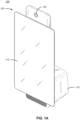
- FIGS. 1A-1B illustrate a communication system 100 in a first mode and in a second mode, in accordance with one or more embodiments.
- the communication system 100 enables communication between users located at different locations.
- the communication system 100 may enable various forms of communication, such as live audio calls and/or video calls, instant messaging, email messaging, or other modes of communication.
- the communication system 100 connects a user with one or more users, individually and/or simultaneously.
- the communication system 100 includes a user device 105 that is secured to a device mount 110.
- the device 105 includes a display 115 that enables a user to view and/or interact with information displayed by the device 105.
- the device mount 110 includes a camera 120 that may capture images and/or video of a user of the user device 105.
- the device 105 is a computing device capable of receiving user input as well as transmitting and/or receiving data via a network.
- the device 105 is a conventional computer system, such as a desktop or a laptop computer, that may be mounted to the device mount 110.
- the device 100 may be a device having computer functionality, such as a personal digital assistant (PDA), a mobile telephone, a smartphone, a tablet, or another suitable device, that may be mounted to the device mount 110.
- PDA personal digital assistant
- the device 100 may be configured to communicate via the network, which connects the device 105 with other devices 105 on the network.
- the device 105 executes an application allowing a user of the device 105 to interact with a communication platform.
- a device 105 executes a browser application to enable interaction between the device 105 and the communication platform via the network.
- a device 105 interacts with the communication platform through an application programming interface (API) running on a native operating system of the device 105, such as IOS ® or ANDROID TM .
- API application programming interface
- Examples of a communication platform may include text and/or messaging applications, email messaging applications, social media applications, videoconferencing applications, or other suitable forms of communication.
- the display 110 may provide a user interface for the user to interact with the device 105, the communication platform, or some combination thereof.
- the display 110 is a touchscreen that is configured to receive user input.
- the display 110 may also display a stream of a video chat, enabling a user to view a video of his/herself, a video of another user of the video chat, or some combination thereof.
- the device mount 110 is a mount that secures the device 105.
- the device mount 110 positions the device 105 such that the display 115 may be comfortably viewed by a user of the device 105.
- the device mount 110 positions the device 105 in a portrait mode, as illustrated in FIG. 1A , or in a landscape mode, as illustrated in FIG. 1B .
- the device mount 110 In the portrait mode, the device 110 is oriented such that its height is greater than its width.
- the device In the landscape mode, the device is oriented such that its width is greater than its height.
- the device mount 110 includes a hinge (shown in, e.g., FIG. 4 ) that transitions the device 105 between the portrait mode and the landscape mode, and vice versa.
- the hinge is actuated by the user such that the user is able to select a preferred mode of the display 115 that is suitable for a use case of the user.
- the device mount 110 includes the camera 120 that may capture images and/or video of a user of the user device 105.
- the hinge is designed such that a top edge (or, alternatively, a center) of the display 115 has a vertical offset from the camera that is the same in both the portrait mode and the landscape mode. In this configuration, an angle of the user's gaze upon the display 115 is approximately the same in either the portrait mode or the landscape mode.
- the device mount 110 is configured to move the device 105 such that the device 105 covers the camera on the device mount 110, for example, in a privacy mode.
- the device mount 110 may include a speaker that is configured to interface with the display 115.
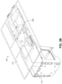
- FIG. 2A illustrates an exploded view of the communication system 100
- FIG. 2B illustrates a perspective view of the communication system 100, in accordance with one or more embodiments.
- the device 105 is mounted to the device mount 110 via a hinge 205.
- the hinge 205 is an assembly comprising stationary components that mount to the device mount 110 and movable components that enable movement of the device 105 relative to the device mount 110.
- the user actuates the hinge 205 by providing user input to, for example, the device 105 that is coupled to the hinge 205 to transition the device 105 between the portrait mode and the landscape mode.
- a movable portion of the hinge 205 is mounted to the device 105 in an off-center position (i.e., not positioned at a center of the device 105).
- the hinge 205 moves the device 105 along a predefined path to change the orientation of the device 105 between the portrait mode and the landscape mode.
- the predefined path may be linear, curved, or some combination thereof, thereby causing the device 105 to translate, rotate, or some combination thereof.
- the hinge 205 is designed to rotate the device 105 along a semi-circular path.
- the hinge is mounted to the device 105 at the center of the device 105 such that a rotational axis of the device 105 is aligned with the center of the device 105. Additional embodiments of the hinge are discussed in further detail herein.
- FIG. 3A illustrates a perspective view of a back side of the communication system 100
- FIG. 3B illustrates a zoomed-in, perspective view of the hinge 205 mounted to the device mount 100, in accordance with one or more embodiments.
- the hinge 205 includes a bearing 305.
- the bearing 305 includes an outer ring 310 and an inner ring 315, where the outer ring 310 is secured within an opening 320 of the device mount 100 and the inner ring 315 is rotatably mounted within the outer ring 310.
- outer ring 310 mounts the stationary components of the hinge 205 to the device mount 100 while the inner ring 315 enables the movable components of the hinge 205 to rotate relative to the device mount 100.
- the hinge 205 includes a single bearing, while alternate embodiments may include more than one bearing.
- FIG. 4 illustrates a front view of an example hinge 400, in accordance with one or more embodiments.
- the hinge 400 mounts the device 105 to the device mount 110 and enables movement of the device 105 relative to the device mount 110.
- the hinge 400 includes a mounting plate 402, a shuttle 404, one or more slots 406, one or more shuttle bushings 408, a bearing cap 410 (shown in FIGS. 5A-5B ), a bearing 412, a torsion spring 414, a spring bushing 416, one or more stop blocks 418, and one or more stop locks 420.
- the hinge 400 may also include counterbalancing components, such as a spring 422, a spring link 424, an adjustment slide 426, and an adjustment screw 428.
- the hinge 400 may also include damping components, such as a gear damping mechanism 430 and a cam damping mechanism 432.
- damping components such as a gear damping mechanism 430 and a cam damping mechanism 432.
- the components are generally made of rigid materials (e.g., hard plastics, metals, or some combination thereof).
- the mounting plate 402 mounts the hinge 400 to the device mount 110.
- the mounting plate 402 is a stationary component that is mounted to the device mount 110 with one or more securing mechanisms (e.g., threaded components and respective threaded interfaces, mounting pins and interference fits, or other suitable securing mechanisms).
- the mounting plate 402 comprises an opening that receives the bearing cap 410, which is designed to secure an outer ring of the bearing 412 such that the outer ring of the bearing 412 remains stationary relative to the device mount 105 and an inner ring of the bearing 412 may freely rotate within the outer ring of the bearing 412 about a pivot point 434 (i.e., the center of the bearing 412).
- the mounting plate 402 comprises several mounting interfaces for securing other components of the hinge 400, which are discussed in further detail.
- the shuttle 404 moves relative to the mounting plate 402.
- the shuttle 404 mounts to the device 105 with one or more securing mechanisms (e.g., threaded components and respective threaded interfaces, mounting pins and interference fits, or other suitable securing mechanisms).
- the shuttle 404 enables movement of the device 105 relative to the mounting plate 402, which is mounted to the device mount 110.
- the shuttle 404 is coupled to the mounting plate 402 with one or more shuttle bushings 408.
- the shuttle 404 includes a first shuttle bushing 408a and a second shuttle bushing 408b, which each fit into respective slots 406a, 406b on the mounting plate 402.
- the shuttle bushings 408 are designed to slide back and forth within the slots 406, and the slots 406 are sized such that the shuttle bushings 408 may move freely within the slots 406 without falling out of the slots 406.
- the shuttle 404 is configured to rotate about the pivot point 434, which causes corresponding movement of the shuttle bushings 408 through the slots 406.
- the slots 406 are a predefined path along which the shuttle 404 moves.
- the slots 406 have a substantially uniform radius of curvature.
- Alternate embodiments may include slots having a different orientation or geometry depending on a type of desired motion for adjusting the orientation of the device 105 from portrait mode to landscape mode, and vice versa.
- the bearing 412 enables rotation of the shuttle 404 about the pivot point 434.
- the bearing 412 is secured within the bearing cap 410.
- the bearing 412 includes an outer ring, an inner ring, and a plurality of balls.
- the outer ring of the bearing 412 remains stationary within the bearing cap 410, and the plurality of balls enable rotation of the inner ring relative to the outer ring.
- the shuttle 404 may include a securing interface that secures to the inner ring of the bearing 412 such that the shuttle 404 and the inner ring rotate together about the pivot point 434.
- the torsion spring 414 provides a bi-stable force to the motion of the shuttle 404 relative to the mounting plate 402.
- a first end of the torsion spring 414 is mounted to the mounting plate 402 with a spring bushing 416, and a second end of the torsion spring 414 is secured is secured to the first shuttle bushing 408a.
- the first end of the torsion spring 414 remains stationary while the second end of the torsion spring 414 moves with the shuttle bushing 408a along the path of the slot 406a.
- the torsion spring 414 is composed of metal wire.
- the stop blocks 418 are features that are positioned on edges of the shuttle 404 to stop rotation of the shuttle 404 about the pivot point 434 at certain endpoints.
- the stop blocks 418 are designed to meet corresponding end stops 436 on the device mount 110 such that the shuttle 404 may not rotate past the end stops 436.
- the stop blocks 418 and end stops 436 ensure that the shuttle 404 stops rotating at certain endpoints such that the device 105 is in a landscape mode or a portrait mode at the endpoints.
- the stop lock 420 is a magnetic component on the shuttle 404 that secures the shuttle 404 in its position at the endpoints.
- the stop lock 420 is designed to meet corresponding magnets 438 on the device mount 110 such that, once the stop blocks 418 meet corresponding end stops 436 at the endpoints, the shuttle 404 is secured into a landscape mode or a portrait mode.
- the shuttle 404 may include more than one stop lock 420, for example, at each corner of the shuttle 404.
- an end stop 436 may also be a magnet.
- the spring 422 provides a counterbalancing force to a mass of the device 105 mounted to the shuttle 404.
- the spring 422 is an extension spring but may be configured as a compression spring in other embodiments.
- a first end of the spring 422 is coupled to the shuttle 404 with the spring link 424, and a second end of the spring 422 is coupled to the adjustment slide 426.
- the adjustment slide 426 includes a threaded interface that mates with the adjustment screw 428. Loosening or tightening the adjustment screw 428 causes the adjustment slide 426 to translate, which enables a tension of the spring 422 to be fine-tuned for the mass of the device 105.
- the gear damping mechanism 430 dampens rotation of the shuttle 404.
- the gear damping mechanism 430 includes a rotary damper 440 and a gear 442.
- the rotary damper 440 is mounted to the mounting plate 402
- the gear 442 is mounted to the shuttle 404.
- the components may be in switched positions.
- the rotary damper 440 and the gear 442 are continuously engaged, which helps to control the rotation of the shuttle 404.
- the gear damping mechanism 430 slows down rotation of the shuttle 404 if actuated quickly and/or forcefully.
- the cam damping mechanism 432 dampens rotation of the shuttle 404 at the end stops 436.
- the cam damping mechanism 432 includes a rotary damper 444 and a cam 446.
- the rotary damper 444 is mounted to the shuttle 404
- the cam 446 is mounted to the mounting plate 402.
- the components may be in switched positions.
- the cam 446 is positioned within a slot 448 in the mounting plate 402 such that the cam 446 slides within the slot 448.
- the cam 446 slides within the slot 448 as the shuttle 404 rotates relative to the mounting plate 402, and at the endpoints of the rotation of the shuttle 404, the cam 446 is designed to abut features on the mounting plate 402.
- the cam 446 While the rotary damper 444 and the cam 446 are continuously engaged, the cam 446 rotates relative to the rotary damper 444 as the cam 446 approaches and abuts the features on the mounting plate 402. In this configuration, the cam damping mechanism 432 dampens rotation near the endpoints of the rotation of the shuttle 404.
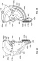
- FIGS. 5A-5B illustrate a front view and a back view of the hinge 400 of FIG. 4 , in accordance with one or more embodiments.
- the spring 422 is uncoupled from the spring link 424.
- FIGS. 6A-6B illustrate a front view and a back view of an example hinge 600, in accordance with one or more embodiments. Similar to the hinge 400, the hinge 600 mounts the device 105 to the device mount 110 and enables movement of the device 105 relative to the device mount 110.
- the hinge 600 includes a mounting plate 602, a shuttle 604, one or more tracks 606, a shuttle bushing 608, a bearing cap 610, two bearings 612, a torsion spring 614, a spring bushing 616, one or more stop blocks 618 (not shown), and one or more stop locks 620 (not shown).
- the hinge 600 may also include counterbalancing components, such as a spring 622, a spring link 624, an adjustment slide 626 (shown in FIG. 7 ), and an adjustment screw 628.
- the hinge 400 may also include damping components, such as a gear damping mechanism 630 and a cam damping mechanism 632.
- the gear damping mechanism 630 includes a rotary damper 640 and a gear 642.
- the cam damping mechanism 632 includes a rotary damper 644 (shown in FIG. 7 ) and a cam 646 that moves within a slot 648.
- the components are generally made of rigid materials (e.g., hard plastics, metals, or some combination thereof).
- the hinge 600 operates similarly to the hinge 400 and has similar components to the hinge 400, such that the corresponding description from FIG. 4 is incorporated herein for FIG. 6 .
- the shuttle 604 includes one shuttle bushing 608, which is designed to slide along a track 606 on the mounting plate 602 (as opposed to sliding in an open slot).
- the hinge 600 includes two bearings 612 that are positioned concentrically. This configuration provides added stability to the shuttle 604 as it moves relative to the mounting plate 602 and minimizes any potential wobble of the device 105 mounted to the hinge 600.
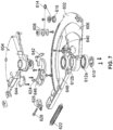
- FIG. 7 illustrates an exploded view of the hinge 600, in accordance with one or more embodiments.
- both bearings 612a, 612b, the adjustment slide 626, and the rotary damper 644 are shown.
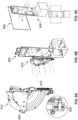
- FIGS. 8A-8C illustrate a process for assembling a device 800 to a device mount 805, in accordance with one or more embodiments.
- a hinge 810 may be assembled using a dummy screen fixture and a device mount fixture, such that the motion of the hinge 810 can be tested before securing it to the device 800 and the device mount 805.
- the spring 815 of the hinge 810 may be tensioned by tightening or loosening the adjustment screw 820. This allows the design to account for changes in a mass of the device 800.
- a fixture may be used to streamline the tensioning of each spring of hinges that are assembled.
- the hinge 810 is positioned onto the device mount 805 by aligning the bearing with its mounting interface on the device mount 805.
- the hinge 810 is secured to the device mount 805 using a plurality of screws.
- the device 800 is positioned onto the hinge 810 by aligning a locating ring on the device 800 with a shuttle 825 of the hinge 810.
- the device 800 is secured to the shuttle 825 using a plurality of screws through a back side of the device mount 805.
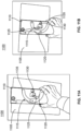
- FIGS. 9A-9D illustrate an example communication system 900, in accordance with one or more embodiments.
- the communication system 900 includes a user device 905 that is secured to a device mount 910 via a hinge 915. While not shown in FIGS. 9A-9D , the communication system 900 may further include a camera that is positioned on the device mount 910 above a top edge of the device 905.
- the hinge 915 is adapted to change the orientation of the device 905 between a portrait mode and a landscape mode, and vice versa.
- a user may provide user input to the device 905 coupled to the hinge 915 to actuate the hinge 915 to transition between the portrait mode and the landscape mode, and vice versa.
- FIGS. 9A-9B illustrate the device 905 and the hinge 915 in a portrait mode
- FIGS. 9C-9D illustrate the device 905 and the hinge 915 in a landscape mode
- FIGS. 9E illustrates a back view of the hinge 915
- FIG. 9F illustrates a first side view and a second side view of the hinge 915.
- the hinge 915 uses a planetary gear system to rotate and translate the device 905 between the portrait mode and the landscape mode.
- Some embodiments may include a constant force spring to counterbalance the planetary gear system.
- FIGS. 10A-10C illustrate variations of an example hinge 1000, in accordance with one or more embodiments.
- the hinge 1000 includes a cam 1005 and a cam follower 1010 that are coupled to a plurality of springs that move the cam follower 1010 about a pivot point 1015.
- the cam follower 1010 is positioned at a 45 degree angle, but the angle may vary in other embodiments.
- FIG. 10B illustrates a hinge 1020 having a cam 1025 having a different geometry that is configured to translate along a slot 1030, thereby causing rotation of the cam 1025 relative to a pin 1035.
- FIG. 10C illustrates the hinge 1040 having a cam 1045 having a different geometry and including two double-acting pins 1050.
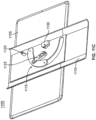
- FIGS. 11A-11C illustrate perspective views of an example communication system 1100, in accordance with one or more embodiments.
- the communication system 1100 includes a user device 1105 that is secured to a device mount 1110 via a hinge 1115.
- the hinge 1115 includes a slider 1120 and an over-center spring 1125 that enable the hinge to rotate about a pivot point 1130.
- FIG. 11A illustrates the communication system 1100 in a portrait mode
- FIG. 11B illustrates the communication system 1100 in a landscape mode.
- the slider 1120 slides through the slot 1135, and the spring 1125 provides a counterbalancing force.
- FIG. 12 illustrates a variation of the hinge of FIGS. 11A-11C , in accordance with one or more embodiments.
- a hinge 1200 is similar to hinge 1115 and further includes a damping mechanism.
- the hinge 1200 includes a damping gear 1205 and a radial damper 1210. The damping mechanism dampens the motion of the hinge 1115 to enable a smooth transition between a portrait mode and a landscape mode.
- FIG. 13 illustrates a variation of the hinge of FIGS. 11A-11C , in accordance with one or more embodiments.
- a hinge 1300 is similar to hinge 1115 and includes a cam 1305 and a plurality of extension springs (not shown) in lieu of the over-center spring 1125.
- the hinge 1300 further includes a back plate 1310 to counter a moment created by a shuttle of the hinge 1300 and the plurality of springs.
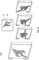
- FIG. 14 illustrates a transition of an example hinge 1400 between a portrait mode and a landscape mode, in accordance with one or more embodiments.
- the hinge 1400 is similar to hinge 1115 in operation, while the hinge 1400 simplifies the attachment mechanism for securing a device, reduces part count, and adds an option to include a linear damper in the hinge 1400.
- FIG. 15 illustrates an example hinge 1500, in accordance with one or more embodiments.
- the hinge 1500 includes a cam 1505 that is coupled to two linear segments 1510, where each segment 1510 includes a dowel pin 1515 at a distal end.
- the dowel pins are designed to move along respective linear tracks as the cam 1505 rotates.
- the linear tracks have an angle of 20 degrees relative to each other.
- FIG. 16 illustrates an example hinge 1600, in accordance with one or more embodiments.
- the hinge 1600 uses a planetary gear system to rotate and translate a device between the portrait mode and the landscape mode.
- the planetary gear system has a pressure angle of 20 degrees.
- FIG. 17 illustrates an example hinge 1700, in accordance with one or more embodiments. Similar to the hinge 1600, the hinge 1700 uses a planetary gear system to rotate and translate a device between the portrait mode and the landscape mode. In the embodiment of FIG. 17 , the planetary gear system has a pressure angle of 20 degrees.
- a software module is implemented with a computer program product comprising a computer-readable medium containing computer program code, which can be executed by a computer processor for performing any or all of the steps, operations, or processes described.
- Embodiments of the disclosure may also relate to an apparatus for performing the operations herein.
- This apparatus may be specially constructed for the required purposes, and/or it may comprise a general-purpose computing device selectively activated or reconfigured by a computer program stored in the computer.
- a computer program may be stored in a non-transitory, tangible computer readable storage medium, or any type of media suitable for storing electronic instructions, which may be coupled to a computer system bus.
- any computing systems referred to in the specification may include a single processor or may be architectures employing multiple processor designs for increased computing capability.
- Embodiments of the disclosure may also relate to a product that is produced by a computing process described herein.
- a product may comprise information resulting from a computing process, where the information is stored on a non-transitory, tangible computer readable storage medium and may include any embodiment of a computer program product or other data combination described herein.
Landscapes
- Engineering & Computer Science (AREA)
- General Engineering & Computer Science (AREA)
- Mechanical Engineering (AREA)
- General Physics & Mathematics (AREA)
- Physics & Mathematics (AREA)
- Signal Processing (AREA)
- Theoretical Computer Science (AREA)
- Microelectronics & Electronic Packaging (AREA)
- Multimedia (AREA)
- Computer Hardware Design (AREA)
- Human Computer Interaction (AREA)
- Studio Devices (AREA)
- Telephone Set Structure (AREA)
- Accessories Of Cameras (AREA)
Claims (15)
- Eine Vorrichtungshalterung (110), die Folgendes beinhaltet:eine Kamera (120), die über einer oberen Kante einer Vorrichtung, die mit der Vorrichtungshalterung gekoppelt ist, positioniert ist; undein Scharnier (205), das konfiguriert ist, um die gekoppelte Vorrichtung zu drehen,wobei das Scharnier Folgendes beinhaltet:eine Montageplatte (402), die konfiguriert ist, um das Scharnier mit der Vorrichtungshalterung zu koppeln;eine Pendelvorrichtung (404), die konfiguriert ist, um die Vorrichtung mit dem Scharnier zu koppeln, wobei sich die Pendelvorrichtung relativ zu der Montageplatte zwischen einem Querformatmodus und einem Hochformatmodus dreht, sodass ein Abstand zwischen einer oberen Oberfläche der gekoppelten Vorrichtung und der Kamera zwischen dem Querformatmodus und dem Hochformatmodus fest bleibt; undgekennzeichnet ist durcheine Feder (422), die konfiguriert ist, um die Drehung der Pendelvorrichtung relativ zu der Montageplatte zu stabilisieren, wobei die Feder Folgendes beinhaltet:ein erstes Ende, das durch eine Federhülse (416) mit der Montageplatte gekoppelt ist; undein zweites Ende, das durch eine Pendelvorrichtungshülse (408a) mit der Pendelvorrichtung gekoppelt ist, wodurch die Montageplatte mit der Pendelvorrichtung gekoppelt ist.
- Vorrichtungshalterung gemäß Anspruch 1, die ferner Folgendes beinhaltet:einen Lagerdeckel, der konfiguriert ist, um in eine Öffnung in der Montageplatte eingefügt zu werden, um die Montageplatte mit der Vorrichtungshalterung zu koppeln;eine Pendelvorrichtungshülse, die konfiguriert ist, um die Montageplatte mit der Pendelvorrichtung zu koppeln; undeinen oder mehrere Sicherungsmechanismen, die konfiguriert sind, um die Vorrichtung mit der Pendelvorrichtung zu koppeln.
- Vorrichtungshalterung gemäß Anspruch 1, wobei die Montageplatte mindestens einen Schlitz beinhaltet, der einen Pfad verfolgt, entlang dem sich die Pendelvorrichtung dreht, und die Pendelvorrichtung konfiguriert ist, um sich um einen Schwenkpunkt zu drehen, wobei die Drehung der Pendelvorrichtung bewirkt, das sich durch jeden Schlitz in der Montageplatte eine Pendelvorrichtungshülse bewegt.
- Vorrichtungshalterung gemäß Anspruch 3, wobei das Scharnier ferner ein Lager beinhaltet, das konfiguriert ist, um die Drehung der Pendelvorrichtung um den Schwenkpunkt zu ermöglichen, wobei das Lager Folgendes beinhaltet:einen Außenring in einer festen Position intern zu dem Lagerdeckel;einen Innenring, der konfiguriert ist, um die Pendelvorrichtung zu sichern, um sich um den Schwenkpunkt zu drehen; undeine Vielzahl von Kugeln, die konfiguriert sind, um die Drehung des Innenrings um den Schwenkpunkt zu ermöglichen.
- Vorrichtungshalterung gemäß Anspruch 1, die ferner Folgendes beinhaltet:mindestens einen Stoppblock, der mit einer Kante der Pendelvorrichtung gekoppelt ist; mindestens einen Endblock, der jedem Stoppblock entspricht, wobei jeder Endblock mit der Vorrichtungshalterung gekoppelt ist, um die Drehung der Pendelvorrichtung bei Kontakt zwischen dem Stoppblock und einem entsprechenden Endblock zu stoppen; undeine Stoppsperre, die konfiguriert ist, um die Pendelvorrichtung in einer Position magnetisch zu sichern, in der der Stoppblock mit dem entsprechenden Endblock in Kontakt kommt.
- Vorrichtungshalterung gemäß Anspruch 5, die ferner Folgendes beinhaltet:
einen Nockendämpfungsmechanismus, der konfiguriert ist, um die Drehung der Pendelvorrichtung an dem Endstopp zu verlangsamen, wobei der Nockendämpfungsmechanismus Folgendes beinhaltet:einen Drehdämpfer, der mit der Pendelvorrichtung gekoppelt ist; undeine Nocke, die mit der Pendelvorrichtung gekoppelt ist, wobei die Nocke positioniert ist, um innerhalb eines Schlitzes in der Montageplatte zu gleiten,während sich die Pendelvorrichtung dreht. - Vorrichtungshalterung gemäß Anspruch 1, die ferner Folgendes beinhaltet:
eine Feder, die konfiguriert ist, um eine Masse der Vorrichtung, die mit der Pendelvorrichtung gekoppelt ist, auszugleichen, wobei die Feder Folgendes beinhaltet:ein erstes Ende, das durch eine Federverknüpfung mit der Pendelvorrichtung gekoppelt ist; undein zweites Ende, das durch eine Schnittstelle mit Gewinde und eine Schraube mit einem Anpassungsgleitstück gekoppelt ist, wobei das Anpassungsgleitstück Anpassungen an einer Spannung der Feder ermöglicht. - Vorrichtungshalterung gemäß Anspruch 1, die ferner Folgendes beinhaltet:
einen Getriebedämpfungsmechanismus, der konfiguriert ist, um die Drehung der Pendelvorrichtung zu verlangsamen, wobei der Getriebedämpfungsmechanismus Folgendes beinhaltet:einen Drehdämpfer, der mit der Montageplatte gekoppelt ist; undein Getriebe, das mit der Pendelvorrichtung gekoppelt ist. - Ein Verfahren zum Zusammenbauen einer Vorrichtungshalterung, wobei das Verfahren Folgendes beinhaltet:Ausrichten einer Montageplatte eines Scharniers nach einer Montageschnittstelle auf der Vorrichtungshalterung;Koppeln des ausgerichteten Scharniers mit der Montageschnittstelle unter Verwendung von einer oder mehreren Schrauben, wobei das Scharnier ferner eine Pendelvorrichtung beinhaltet, die konfiguriert ist, um sich zwischen einem Querformatmodus und einem Hochformatmodus relativ zu der Montageplatte zu drehen;Ausrichten eines Lokalisierungsrings auf einer Vorrichtung nach der Pendelvorrichtung des Scharniers;Koppeln der ausgerichteten Vorrichtung mit der Pendelvorrichtung des Scharniers unter Verwendung von einer oder mehreren Schrauben; und gekennzeichnet ist durchdas Stabilisieren der Drehung der Pendelvorrichtung relativ zu der Montageplatte mit einer Feder, wobei die Feder Folgendes beinhaltet:
ein erstes Ende, das durch eine Federhülse mit der Montageplatte gekoppelt ist; und ein zweites Ende, das durch eine Pendelvorrichtungshülse mit der Pendelvorrichtung gekoppelt ist, wodurch die Montageplatte mit der Pendelvorrichtung gekoppelt ist. - Verfahren gemäß Anspruch 9, das ferner Folgendes beinhaltet:Einfügen eines Lagerdeckels in eine Öffnung in der Montageplatte, um die Montageplatte mit der Vorrichtungshalterung zu koppeln;Koppeln der Montageplatte mit der Pendelvorrichtung durch eine Pendelvorrichtungshülse; undKoppeln des Lokalisierungsrings der Vorrichtung mit der Pendelvorrichtung durch einen oder mehrere Sicherungsmechanismen.
- Verfahren gemäß Anspruch 9, das ferner Folgendes beinhaltet:
Drehen der Pendelvorrichtung um einen Schwenkpunkt, wobei die Drehung der Pendelvorrichtung bewirkt, dass sich eine Pendelvorrichtungshülse durch einen Schlitz in der Montageplatte bewegt, entlang dem sich die Pendelvorrichtung dreht. - Verfahren gemäß Anspruch 11, wobei das Scharnier ferner ein Lager beinhaltet, das konfiguriert ist, um die Drehung der Pendelvorrichtung um den Schwenkpunkt zu ermöglichen, wobei das Lager Folgendes beinhaltet:einen Außenring in einer festen Position intern zu dem Lagerdeckel;einen Innenring, der konfiguriert ist, um die Pendelvorrichtung zu sichern, um sich um den Schwenkpunkt zu drehen; undeine Vielzahl von Kugeln, die konfiguriert sind, um die Drehung des Innenrings um den Schwenkpunkt zu ermöglichen.
- Verfahren gemäß Anspruch 9, das ferner Folgendes beinhaltet:Stoppen der Drehung der Pendelvorrichtung bei Kontakt zwischen einem Stoppblock, der mit einer Kante der Pendelvorrichtung gekoppelt ist, und einem entsprechenden Endblock, der mit der Vorrichtungshalterung gekoppelt ist; undmagnetisches Sichern, durch eine Stoppsperre, der Pendelvorrichtung in einer Position, in der der Stoppblock den entsprechenden Endblock kontaktiert.
- Verfahren gemäß Anspruch 13, das ferner Folgendes beinhaltet:Verlangsamen der Drehung der Pendelvorrichtung an dem Endstopp unter Verwendung eines Nockendämpfungsmechanismus, wobei der Nockendämpfungsmechanismus Folgendes beinhaltet:einen Drehdämpfer, der mit der Pendelvorrichtung gekoppelt ist; undeine Nocke, die mit der Pendelvorrichtung gekoppelt ist, wobei die Nocke positioniert ist, um innerhalb eines Schlitzes in der Montageplatte zu gleiten, während sich die Pendelvorrichtung dreht; und, optional,Ausgleichen einer Masse der Vorrichtung, die mit der Pendelvorrichtung gekoppelt ist, durch eine Feder, wobei die Feder Folgendes beinhaltet:ein erstes Ende, das durch eine Federverknüpfung mit der Pendelvorrichtung gekoppelt ist; undein zweites Ende, das durch eine Schnittstelle mit Gewinde und eine Schraube mit einem Anpassungsgleitstück gekoppelt ist, wobei das Anpassungsgleitstück Anpassungen an einer Spannung der Feder ermöglicht.
- Verfahren gemäß Anspruch 9, das ferner Folgendes beinhaltet:
Verlangsamen der Drehung der Pendelvorrichtung unter Verwendung eines Getriebedämpfungsmechanismus, wobei der Getriebedämpfungsmechanismus Folgendes beinhaltet:einen Drehdämpfer, der mit der Montageplatte gekoppelt ist; undein Getriebe, das mit der Pendelvorrichtung gekoppelt ist.
Applications Claiming Priority (3)
| Application Number | Priority Date | Filing Date | Title |
|---|---|---|---|
| US201862742175P | 2018-10-05 | 2018-10-05 | |
| US16/589,062 US11425830B2 (en) | 2018-10-05 | 2019-09-30 | Hinge mechanism of a device mount |
| PCT/US2019/054452 WO2020072752A1 (en) | 2018-10-05 | 2019-10-03 | Hinge mechanism of a device mount |
Publications (2)
| Publication Number | Publication Date |
|---|---|
| EP3861239A1 EP3861239A1 (de) | 2021-08-11 |
| EP3861239B1 true EP3861239B1 (de) | 2023-06-28 |
Family
ID=70051362
Family Applications (1)
| Application Number | Title | Priority Date | Filing Date |
|---|---|---|---|
| EP19791084.7A Active EP3861239B1 (de) | 2018-10-05 | 2019-10-03 | Vorrichtungshalterung |
Country Status (4)
| Country | Link |
|---|---|
| US (1) | US11425830B2 (de) |
| EP (1) | EP3861239B1 (de) |
| CN (1) | CN112789441B (de) |
| WO (1) | WO2020072752A1 (de) |
Families Citing this family (8)
| Publication number | Priority date | Publication date | Assignee | Title |
|---|---|---|---|---|
| CN114071198A (zh) * | 2020-07-31 | 2022-02-18 | 北京字节跳动网络技术有限公司 | 电子设备、控制方法及直播系统 |
| KR102936940B1 (ko) | 2020-08-07 | 2026-03-09 | 엘지디스플레이 주식회사 | 디스플레이 장치 |
| CN112532841A (zh) * | 2020-11-26 | 2021-03-19 | 深圳卡多希科技有限公司 | 一种直播设备 |
| CN112555588B (zh) * | 2020-12-01 | 2022-08-19 | 联想(北京)有限公司 | 支撑装置和电子设备 |
| CN216241794U (zh) * | 2021-07-05 | 2022-04-08 | 武汉华星光电半导体显示技术有限公司 | 铰链、柔性显示面板及电子装置 |
| CN114017638B (zh) * | 2021-11-05 | 2023-09-15 | 深圳市绿联科技股份有限公司 | 一种多功能电子设备支架 |
| CN114364199B (zh) * | 2021-12-30 | 2023-07-21 | 联想(北京)有限公司 | 一种电子设备 |
| USD1119903S1 (en) * | 2025-05-16 | 2026-03-24 | Pattinson Hayton | Display panel |
Family Cites Families (16)
| Publication number | Priority date | Publication date | Assignee | Title |
|---|---|---|---|---|
| US1201328A (en) * | 1914-10-06 | 1916-10-17 | George R Moran | Ball-bearing. |
| US5779309A (en) * | 1997-09-02 | 1998-07-14 | Lu; Cheng-Ho | Swivel plate device |
| US6189842B1 (en) | 1999-06-21 | 2001-02-20 | Palo Alto Design Group | Tilt and swivel adjustment of flat panel display having detents for landscape and portrait positions and kickout for preventing contact between flat panel display and base |
| EP1488060A2 (de) | 2001-05-12 | 2004-12-22 | Southco, Inc. | Scharniermechanismus mit arretierung und dämpfung |
| FR2842854B1 (fr) | 2002-07-12 | 2007-03-09 | Southco | Charniere detendue-amortie a verrouillage inertiel |
| US7092246B2 (en) * | 2003-11-18 | 2006-08-15 | Kabushiki Kaisha Toshiba | Apparatus for connecting a display to a body case of an electronic device |
| JPWO2010023961A1 (ja) * | 2008-08-29 | 2012-01-26 | 日本電気株式会社 | スライド機構及びこれを備えた携帯型通信端末、並びにスライド移動方法 |
| US8471820B2 (en) * | 2011-03-28 | 2013-06-25 | Research In Motion Limited | Pivotable display guide mechanism for an electronic mobile device |
| US8831415B2 (en) | 2012-07-12 | 2014-09-09 | Nitroworks Corporation | Rotating camera mount with counterweight |
| DE102012015484A1 (de) | 2012-08-07 | 2014-05-15 | Esselte Leitz Gmbh & Co. Kg | Haltevorrichtung |
| CN104948881A (zh) | 2015-04-29 | 2015-09-30 | 韦道义 | 可自动调节高度的显示器支架 |
| TWM513310U (zh) | 2015-08-21 | 2015-12-01 | Syncmold Entpr Corp | 用以支撐顯示裝置的支撐座 |
| TWI598723B (zh) * | 2016-05-24 | 2017-09-11 | 鴻海精密工業股份有限公司 | 攝像頭固定裝置 |
| GB2558935B (en) | 2017-01-20 | 2020-01-29 | Sbfi Ltd | Improvements in display screen mounting |
| US9980561B1 (en) | 2017-05-10 | 2018-05-29 | Myworld Mediastudio, Inc. | Mobile multimedia workstation with novel clamp |
| KR102393729B1 (ko) * | 2017-08-31 | 2022-05-04 | 삼성전자주식회사 | 디스플레이 장치 |
-
2019
- 2019-09-30 US US16/589,062 patent/US11425830B2/en active Active
- 2019-10-03 CN CN201980065311.7A patent/CN112789441B/zh not_active Expired - Fee Related
- 2019-10-03 WO PCT/US2019/054452 patent/WO2020072752A1/en not_active Ceased
- 2019-10-03 EP EP19791084.7A patent/EP3861239B1/de active Active
Also Published As
| Publication number | Publication date |
|---|---|
| EP3861239A1 (de) | 2021-08-11 |
| CN112789441B (zh) | 2022-09-06 |
| US11425830B2 (en) | 2022-08-23 |
| US20200113073A1 (en) | 2020-04-09 |
| WO2020072752A1 (en) | 2020-04-09 |
| CN112789441A (zh) | 2021-05-11 |
Similar Documents
| Publication | Publication Date | Title |
|---|---|---|
| EP3861239B1 (de) | Vorrichtungshalterung | |
| US11662769B2 (en) | Foldable electronic device | |
| US7448872B2 (en) | Portable terminal having display unit cradled on a slant | |
| US9939851B2 (en) | Electronic device and hinge thereof | |
| US7738930B2 (en) | Hinge mechanism for a portable electronic device | |
| WO2020092042A1 (en) | Electronic device with flexible display | |
| EP2242237B1 (de) | Tragbare elektronische Vorrichtung | |
| CN101469736B (zh) | 铰链结构 | |
| CN100593317C (zh) | 移动电话配置 | |
| US20120176740A1 (en) | Electronic apparatus and hinge | |
| CN112334966A (zh) | 具有柔性显示器的电子设备 | |
| US10168746B2 (en) | Hinge mechanism for a computing device | |
| CN1774004A (zh) | 具有三支柱式支架功能的便携式通信设备 | |
| US9069457B2 (en) | Portable terminal | |
| US20100299876A1 (en) | Hinge | |
| CN1921506A (zh) | 便携式通信装置及用于其的摆转铰链模块 | |
| US7024729B2 (en) | Rotation apparatus | |
| WO2019042336A1 (zh) | 一种自动打开的铰链 | |
| US8084689B2 (en) | Hinge assembly and electronic device using the same | |
| CN110630628A (zh) | 转轴结构和电子设备 | |
| JP2007271062A (ja) | ヒンジ装置及びヒンジ装置を備える機器 | |
| WO2019037621A1 (zh) | 一种铰链 | |
| CN201765539U (zh) | 可携式电子装置 | |
| KR20070065189A (ko) | 힌지장치 및 이를 구비한 모바일 기기 | |
| KR200402929Y1 (ko) | 핸드폰용 힌지 |
Legal Events
| Date | Code | Title | Description |
|---|---|---|---|
| STAA | Information on the status of an ep patent application or granted ep patent |
Free format text: STATUS: UNKNOWN |
|
| STAA | Information on the status of an ep patent application or granted ep patent |
Free format text: STATUS: THE INTERNATIONAL PUBLICATION HAS BEEN MADE |
|
| PUAI | Public reference made under article 153(3) epc to a published international application that has entered the european phase |
Free format text: ORIGINAL CODE: 0009012 |
|
| STAA | Information on the status of an ep patent application or granted ep patent |
Free format text: STATUS: REQUEST FOR EXAMINATION WAS MADE |
|
| 17P | Request for examination filed |
Effective date: 20210505 |
|
| AK | Designated contracting states |
Kind code of ref document: A1 Designated state(s): AL AT BE BG CH CY CZ DE DK EE ES FI FR GB GR HR HU IE IS IT LI LT LU LV MC MK MT NL NO PL PT RO RS SE SI SK SM TR |
|
| DAV | Request for validation of the european patent (deleted) | ||
| DAX | Request for extension of the european patent (deleted) | ||
| RAP3 | Party data changed (applicant data changed or rights of an application transferred) |
Owner name: META PLATFORMS, INC. |
|
| GRAP | Despatch of communication of intention to grant a patent |
Free format text: ORIGINAL CODE: EPIDOSNIGR1 |
|
| STAA | Information on the status of an ep patent application or granted ep patent |
Free format text: STATUS: GRANT OF PATENT IS INTENDED |
|
| INTG | Intention to grant announced |
Effective date: 20221202 |
|
| GRAJ | Information related to disapproval of communication of intention to grant by the applicant or resumption of examination proceedings by the epo deleted |
Free format text: ORIGINAL CODE: EPIDOSDIGR1 |
|
| STAA | Information on the status of an ep patent application or granted ep patent |
Free format text: STATUS: REQUEST FOR EXAMINATION WAS MADE |
|
| INTC | Intention to grant announced (deleted) | ||
| GRAP | Despatch of communication of intention to grant a patent |
Free format text: ORIGINAL CODE: EPIDOSNIGR1 |
|
| STAA | Information on the status of an ep patent application or granted ep patent |
Free format text: STATUS: GRANT OF PATENT IS INTENDED |
|
| GRAS | Grant fee paid |
Free format text: ORIGINAL CODE: EPIDOSNIGR3 |
|
| GRAA | (expected) grant |
Free format text: ORIGINAL CODE: 0009210 |
|
| STAA | Information on the status of an ep patent application or granted ep patent |
Free format text: STATUS: THE PATENT HAS BEEN GRANTED |
|
| INTG | Intention to grant announced |
Effective date: 20230504 |
|
| AK | Designated contracting states |
Kind code of ref document: B1 Designated state(s): AL AT BE BG CH CY CZ DE DK EE ES FI FR GB GR HR HU IE IS IT LI LT LU LV MC MK MT NL NO PL PT RO RS SE SI SK SM TR |
|
| REG | Reference to a national code |
Ref country code: CH Ref legal event code: EP |
|
| P01 | Opt-out of the competence of the unified patent court (upc) registered |
Effective date: 20230525 |
|
| REG | Reference to a national code |
Ref country code: AT Ref legal event code: REF Ref document number: 1582959 Country of ref document: AT Kind code of ref document: T Effective date: 20230715 |
|
| REG | Reference to a national code |
Ref country code: IE Ref legal event code: FG4D |
|
| REG | Reference to a national code |
Ref country code: DE Ref legal event code: R096 Ref document number: 602019031819 Country of ref document: DE |
|
| REG | Reference to a national code |
Ref country code: LT Ref legal event code: MG9D |
|
| PG25 | Lapsed in a contracting state [announced via postgrant information from national office to epo] |
Ref country code: SE Free format text: LAPSE BECAUSE OF FAILURE TO SUBMIT A TRANSLATION OF THE DESCRIPTION OR TO PAY THE FEE WITHIN THE PRESCRIBED TIME-LIMIT Effective date: 20230628 Ref country code: NO Free format text: LAPSE BECAUSE OF FAILURE TO SUBMIT A TRANSLATION OF THE DESCRIPTION OR TO PAY THE FEE WITHIN THE PRESCRIBED TIME-LIMIT Effective date: 20230928 |
|
| REG | Reference to a national code |
Ref country code: NL Ref legal event code: MP Effective date: 20230628 |
|
| REG | Reference to a national code |
Ref country code: AT Ref legal event code: MK05 Ref document number: 1582959 Country of ref document: AT Kind code of ref document: T Effective date: 20230628 |
|
| PG25 | Lapsed in a contracting state [announced via postgrant information from national office to epo] |
Ref country code: RS Free format text: LAPSE BECAUSE OF FAILURE TO SUBMIT A TRANSLATION OF THE DESCRIPTION OR TO PAY THE FEE WITHIN THE PRESCRIBED TIME-LIMIT Effective date: 20230628 Ref country code: NL Free format text: LAPSE BECAUSE OF FAILURE TO SUBMIT A TRANSLATION OF THE DESCRIPTION OR TO PAY THE FEE WITHIN THE PRESCRIBED TIME-LIMIT Effective date: 20230628 Ref country code: LV Free format text: LAPSE BECAUSE OF FAILURE TO SUBMIT A TRANSLATION OF THE DESCRIPTION OR TO PAY THE FEE WITHIN THE PRESCRIBED TIME-LIMIT Effective date: 20230628 Ref country code: LT Free format text: LAPSE BECAUSE OF FAILURE TO SUBMIT A TRANSLATION OF THE DESCRIPTION OR TO PAY THE FEE WITHIN THE PRESCRIBED TIME-LIMIT Effective date: 20230628 Ref country code: HR Free format text: LAPSE BECAUSE OF FAILURE TO SUBMIT A TRANSLATION OF THE DESCRIPTION OR TO PAY THE FEE WITHIN THE PRESCRIBED TIME-LIMIT Effective date: 20230628 Ref country code: GR Free format text: LAPSE BECAUSE OF FAILURE TO SUBMIT A TRANSLATION OF THE DESCRIPTION OR TO PAY THE FEE WITHIN THE PRESCRIBED TIME-LIMIT Effective date: 20230929 |
|
| PG25 | Lapsed in a contracting state [announced via postgrant information from national office to epo] |
Ref country code: FI Free format text: LAPSE BECAUSE OF FAILURE TO SUBMIT A TRANSLATION OF THE DESCRIPTION OR TO PAY THE FEE WITHIN THE PRESCRIBED TIME-LIMIT Effective date: 20230628 |
|
| PG25 | Lapsed in a contracting state [announced via postgrant information from national office to epo] |
Ref country code: SK Free format text: LAPSE BECAUSE OF FAILURE TO SUBMIT A TRANSLATION OF THE DESCRIPTION OR TO PAY THE FEE WITHIN THE PRESCRIBED TIME-LIMIT Effective date: 20230628 |
|
| PG25 | Lapsed in a contracting state [announced via postgrant information from national office to epo] |
Ref country code: ES Free format text: LAPSE BECAUSE OF FAILURE TO SUBMIT A TRANSLATION OF THE DESCRIPTION OR TO PAY THE FEE WITHIN THE PRESCRIBED TIME-LIMIT Effective date: 20230628 |
|
| PG25 | Lapsed in a contracting state [announced via postgrant information from national office to epo] |
Ref country code: IS Free format text: LAPSE BECAUSE OF FAILURE TO SUBMIT A TRANSLATION OF THE DESCRIPTION OR TO PAY THE FEE WITHIN THE PRESCRIBED TIME-LIMIT Effective date: 20231028 |
|
| PG25 | Lapsed in a contracting state [announced via postgrant information from national office to epo] |
Ref country code: SM Free format text: LAPSE BECAUSE OF FAILURE TO SUBMIT A TRANSLATION OF THE DESCRIPTION OR TO PAY THE FEE WITHIN THE PRESCRIBED TIME-LIMIT Effective date: 20230628 Ref country code: SK Free format text: LAPSE BECAUSE OF FAILURE TO SUBMIT A TRANSLATION OF THE DESCRIPTION OR TO PAY THE FEE WITHIN THE PRESCRIBED TIME-LIMIT Effective date: 20230628 Ref country code: RO Free format text: LAPSE BECAUSE OF FAILURE TO SUBMIT A TRANSLATION OF THE DESCRIPTION OR TO PAY THE FEE WITHIN THE PRESCRIBED TIME-LIMIT Effective date: 20230628 Ref country code: PT Free format text: LAPSE BECAUSE OF FAILURE TO SUBMIT A TRANSLATION OF THE DESCRIPTION OR TO PAY THE FEE WITHIN THE PRESCRIBED TIME-LIMIT Effective date: 20231030 Ref country code: IS Free format text: LAPSE BECAUSE OF FAILURE TO SUBMIT A TRANSLATION OF THE DESCRIPTION OR TO PAY THE FEE WITHIN THE PRESCRIBED TIME-LIMIT Effective date: 20231028 Ref country code: ES Free format text: LAPSE BECAUSE OF FAILURE TO SUBMIT A TRANSLATION OF THE DESCRIPTION OR TO PAY THE FEE WITHIN THE PRESCRIBED TIME-LIMIT Effective date: 20230628 Ref country code: EE Free format text: LAPSE BECAUSE OF FAILURE TO SUBMIT A TRANSLATION OF THE DESCRIPTION OR TO PAY THE FEE WITHIN THE PRESCRIBED TIME-LIMIT Effective date: 20230628 Ref country code: CZ Free format text: LAPSE BECAUSE OF FAILURE TO SUBMIT A TRANSLATION OF THE DESCRIPTION OR TO PAY THE FEE WITHIN THE PRESCRIBED TIME-LIMIT Effective date: 20230628 Ref country code: AT Free format text: LAPSE BECAUSE OF FAILURE TO SUBMIT A TRANSLATION OF THE DESCRIPTION OR TO PAY THE FEE WITHIN THE PRESCRIBED TIME-LIMIT Effective date: 20230628 |
|
| PG25 | Lapsed in a contracting state [announced via postgrant information from national office to epo] |
Ref country code: PL Free format text: LAPSE BECAUSE OF FAILURE TO SUBMIT A TRANSLATION OF THE DESCRIPTION OR TO PAY THE FEE WITHIN THE PRESCRIBED TIME-LIMIT Effective date: 20230628 |
|
| REG | Reference to a national code |
Ref country code: DE Ref legal event code: R097 Ref document number: 602019031819 Country of ref document: DE |
|
| PG25 | Lapsed in a contracting state [announced via postgrant information from national office to epo] |
Ref country code: DK Free format text: LAPSE BECAUSE OF FAILURE TO SUBMIT A TRANSLATION OF THE DESCRIPTION OR TO PAY THE FEE WITHIN THE PRESCRIBED TIME-LIMIT Effective date: 20230628 |
|
| PLBE | No opposition filed within time limit |
Free format text: ORIGINAL CODE: 0009261 |
|
| STAA | Information on the status of an ep patent application or granted ep patent |
Free format text: STATUS: NO OPPOSITION FILED WITHIN TIME LIMIT |
|
| PG25 | Lapsed in a contracting state [announced via postgrant information from national office to epo] |
Ref country code: IT Free format text: LAPSE BECAUSE OF FAILURE TO SUBMIT A TRANSLATION OF THE DESCRIPTION OR TO PAY THE FEE WITHIN THE PRESCRIBED TIME-LIMIT Effective date: 20230628 Ref country code: MC Free format text: LAPSE BECAUSE OF FAILURE TO SUBMIT A TRANSLATION OF THE DESCRIPTION OR TO PAY THE FEE WITHIN THE PRESCRIBED TIME-LIMIT Effective date: 20230628 |
|
| REG | Reference to a national code |
Ref country code: CH Ref legal event code: PL |
|
| 26N | No opposition filed |
Effective date: 20240402 |
|
| REG | Reference to a national code |
Ref country code: BE Ref legal event code: MM Effective date: 20231031 |
|
| PG25 | Lapsed in a contracting state [announced via postgrant information from national office to epo] |
Ref country code: LU Free format text: LAPSE BECAUSE OF NON-PAYMENT OF DUE FEES Effective date: 20231003 |
|
| PG25 | Lapsed in a contracting state [announced via postgrant information from national office to epo] |
Ref country code: LU Free format text: LAPSE BECAUSE OF NON-PAYMENT OF DUE FEES Effective date: 20231003 |
|
| PG25 | Lapsed in a contracting state [announced via postgrant information from national office to epo] |
Ref country code: CH Free format text: LAPSE BECAUSE OF NON-PAYMENT OF DUE FEES Effective date: 20231031 |
|
| PG25 | Lapsed in a contracting state [announced via postgrant information from national office to epo] |
Ref country code: FR Free format text: LAPSE BECAUSE OF NON-PAYMENT OF DUE FEES Effective date: 20231031 Ref country code: CH Free format text: LAPSE BECAUSE OF NON-PAYMENT OF DUE FEES Effective date: 20231031 Ref country code: SI Free format text: LAPSE BECAUSE OF FAILURE TO SUBMIT A TRANSLATION OF THE DESCRIPTION OR TO PAY THE FEE WITHIN THE PRESCRIBED TIME-LIMIT Effective date: 20230628 |
|
| PG25 | Lapsed in a contracting state [announced via postgrant information from national office to epo] |
Ref country code: BE Free format text: LAPSE BECAUSE OF NON-PAYMENT OF DUE FEES Effective date: 20231031 |
|
| PG25 | Lapsed in a contracting state [announced via postgrant information from national office to epo] |
Ref country code: IE Free format text: LAPSE BECAUSE OF NON-PAYMENT OF DUE FEES Effective date: 20231003 |
|
| PG25 | Lapsed in a contracting state [announced via postgrant information from national office to epo] |
Ref country code: IE Free format text: LAPSE BECAUSE OF NON-PAYMENT OF DUE FEES Effective date: 20231003 |
|
| PG25 | Lapsed in a contracting state [announced via postgrant information from national office to epo] |
Ref country code: BG Free format text: LAPSE BECAUSE OF FAILURE TO SUBMIT A TRANSLATION OF THE DESCRIPTION OR TO PAY THE FEE WITHIN THE PRESCRIBED TIME-LIMIT Effective date: 20230628 |
|
| PG25 | Lapsed in a contracting state [announced via postgrant information from national office to epo] |
Ref country code: BG Free format text: LAPSE BECAUSE OF FAILURE TO SUBMIT A TRANSLATION OF THE DESCRIPTION OR TO PAY THE FEE WITHIN THE PRESCRIBED TIME-LIMIT Effective date: 20230628 |
|
| PG25 | Lapsed in a contracting state [announced via postgrant information from national office to epo] |
Ref country code: CY Free format text: LAPSE BECAUSE OF FAILURE TO SUBMIT A TRANSLATION OF THE DESCRIPTION OR TO PAY THE FEE WITHIN THE PRESCRIBED TIME-LIMIT; INVALID AB INITIO Effective date: 20191003 |
|
| PG25 | Lapsed in a contracting state [announced via postgrant information from national office to epo] |
Ref country code: HU Free format text: LAPSE BECAUSE OF FAILURE TO SUBMIT A TRANSLATION OF THE DESCRIPTION OR TO PAY THE FEE WITHIN THE PRESCRIBED TIME-LIMIT; INVALID AB INITIO Effective date: 20191003 |
|
| PG25 | Lapsed in a contracting state [announced via postgrant information from national office to epo] |
Ref country code: TR Free format text: LAPSE BECAUSE OF FAILURE TO SUBMIT A TRANSLATION OF THE DESCRIPTION OR TO PAY THE FEE WITHIN THE PRESCRIBED TIME-LIMIT Effective date: 20230628 |
|
| PGFP | Annual fee paid to national office [announced via postgrant information from national office to epo] |
Ref country code: DE Payment date: 20251031 Year of fee payment: 7 |
|
| PGFP | Annual fee paid to national office [announced via postgrant information from national office to epo] |
Ref country code: GB Payment date: 20251031 Year of fee payment: 7 |