EP3860016B1 - Informationsverarbeitungsverfahren, vorrichtung und speichermedium - Google Patents
Informationsverarbeitungsverfahren, vorrichtung und speichermedium Download PDFInfo
- Publication number
- EP3860016B1 EP3860016B1 EP18935271.9A EP18935271A EP3860016B1 EP 3860016 B1 EP3860016 B1 EP 3860016B1 EP 18935271 A EP18935271 A EP 18935271A EP 3860016 B1 EP3860016 B1 EP 3860016B1
- Authority
- EP
- European Patent Office
- Prior art keywords
- rmsi
- symbol
- slot
- coreset
- ssbs
- Prior art date
- Legal status (The legal status is an assumption and is not a legal conclusion. Google has not performed a legal analysis and makes no representation as to the accuracy of the status listed.)
- Active
Links
Images

Classifications
-
- H—ELECTRICITY
- H04—ELECTRIC COMMUNICATION TECHNIQUE
- H04L—TRANSMISSION OF DIGITAL INFORMATION, e.g. TELEGRAPHIC COMMUNICATION
- H04L5/00—Arrangements affording multiple use of the transmission path
- H04L5/003—Arrangements for allocating sub-channels of the transmission path
- H04L5/0048—Allocation of pilot signals, i.e. of signals known to the receiver
-
- H—ELECTRICITY
- H04—ELECTRIC COMMUNICATION TECHNIQUE
- H04W—WIRELESS COMMUNICATION NETWORKS
- H04W72/00—Local resource management
- H04W72/20—Control channels or signalling for resource management
- H04W72/23—Control channels or signalling for resource management in the downlink direction of a wireless link, i.e. towards a terminal
-
- H—ELECTRICITY
- H04—ELECTRIC COMMUNICATION TECHNIQUE
- H04W—WIRELESS COMMUNICATION NETWORKS
- H04W56/00—Synchronisation arrangements
- H04W56/001—Synchronization between nodes
- H04W56/0015—Synchronization between nodes one node acting as a reference for the others
-
- H—ELECTRICITY
- H04—ELECTRIC COMMUNICATION TECHNIQUE
- H04W—WIRELESS COMMUNICATION NETWORKS
- H04W72/00—Local resource management
- H04W72/04—Wireless resource allocation
- H04W72/044—Wireless resource allocation based on the type of the allocated resource
- H04W72/0446—Resources in time domain, e.g. slots or frames
Definitions
- the present disclosure relate to the field of wireless communication technologies, and more particularly, to an information processing method and device.
- time-domain candidate positions for sending a synchronization signal block (SS/PBCH block, SSB) and time-domain candidate positions of a control resource set (CORESET) where a physical downlink control channel (PDCCH) of remaining minimum system information (RMSI) associated with the SSB is located are specified.
- PDCCH physical downlink control channel
- RMSI remaining minimum system information
- embodiments of the present disclosure provide an information processing method performed by a terminal device according to claim 1, an inter-related information processing method performed by a network device according to claim 3 and corresponding terminal device and network device according to claims 5-6, so that a terminal device can receive at most two SSBs in one slot, and detects PDCCHs of RMSI on CORESETs of the RMSI in one-to-one association with the at most two SSBs.
- the candidate sending position of the SSB is planned and configured within 5ms
- a candidate configuration position of the CORESET of the RMSI associated with the SSB is planned and configured within 20ms.
- a time domain interval between the positions of a certain SSB and the CORESET of the RMSI associated with the SSB varies greatly according to different configurations.
- LBT listen before talk
- the SSB and CORESET of RMSI associated are configured and sent as a whole, which will facilitate efficient use of resources and avoid frequent beam switching.
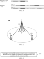
- the candidate sending position of the SSB in one slot is shown in FIG. 1 .
- the CORESET of a first RMSI is configured to start at a first symbol in the slot and have a length L;
- the CORESET of a second RMSI is configured to start at (L+1) th symbol in the slot, or at an 8th symbol in the slot, and have a length L.
- L may be a length of 1 symbol, 2 symbols or 3 symbols.
- the information transmission method in the embodiments of the present application can be applied to a variety of communications systems, such as a Global System for Mobile communications ("GSM” for short) system, a Code Division Multiple Access (“CDMA” for short) system, a Wideband Code Division Multiple Access (“WCDMA” for short) system, a General Packet Radio Service (“GPRS” for short), a Long Term Evolution (“LTE” for short) system, an LTE Frequency Division Duplex (“FDD” for short) system, an LTE Time Division Duplex (“TDD” for short), a Universal Mobile Telecommunication System (“UMTS” for short), a Worldwide Interoperability for Microwave Access (“WiMAX” for short) communications system, a 5G system, or the like.
- GSM Global System for Mobile communications
- CDMA Code Division Multiple Access
- WCDMA Wideband Code Division Multiple Access
- GPRS General Packet Radio Service
- LTE Long Term Evolution
- FDD Frequency Division Duplex
- TDD Time Division Duplex
- UMTS Universal
- the communication system 100 may include a network device 110.
- the network device 110 may be a device communicating with user equipment (UE) 120 (or referred to as a communication terminal or a terminal).
- UE user equipment
- the network device 110 may provide communication coverage to a specific geographic region, and may communicate with UE located within the coverage region.
- the network device 110 may be a base transceiver station (BTS) in a global system for mobile communications (GSM) or a code division multiple access (CDMA) system, or a nodeB (NB) in a wideband code division multiple access (WCDMA) system, or an evolutional node B (eNB or eNodeB) in a long term evolution (LTE) system, or a radio controller in a cloud radio access network (CRAN).
- BTS base transceiver station
- GSM global system for mobile communications
- CDMA code division multiple access
- NB wideband code division multiple access
- eNB or eNodeB evolutional node B
- LTE long term evolution
- CRAN cloud radio access network
- the network device may be a mobile switching center, a relay station, an access point, a vehicle device, a wearable device, a concentrator, a switchboard, a network bridge, a router, a network-side device in a 5th generation (5G) network, or a network device in a public land mobile network (PLMN) that will be evolved in the future, and the like.
- 5G 5th generation
- PLMN public land mobile network
- the communication system 100 further includes at least one UE 120 located within a coverage range of the network device 110.
- the "UE" used herein includes, but not limited to, connection via a wired line, such as connection via public switched telephone networks (PSTN), a digital subscriber line (DSL), a digital cable, and a direct cable; and/or another data connection/network; and/or via a wireless interface, for example, for a cellular network, a wireless local area network (WLAN), a digital television network such as a DVB-H network, a satellite network and an AM-FM broadcast transmitter; and/or an apparatus of another UE, which is configured to receive/transmit a communication signal; and/or an Internet of things (IoT) device.
- PSTN public switched telephone networks
- DSL digital subscriber line
- a digital cable and a direct cable
- a wireless interface for example, for a cellular network, a wireless local area network (WLAN), a digital television network such as a DVB-H network, a
- the UE configured to realize communication through a wireless interface may be referred to as a "wireless communication terminal", a “wireless terminal”, or a “mobile terminal”.
- the mobile terminal include, but not limited to, a satellite or cellular phone, and a personal communications system (PCS) terminal that may combine a cellular radiotelephone with data processing, facsimile, and data communication capabilities; a radiotelephone, a pager, an Internet/intranet access, a Web browser, a notepad, a calendar, and/or a personal digital assistant (PDA) of a global positioning system (GPS) receiver; and a conventional laptop and/or palmtop receiver or other electronic apparatuses including radiotelephone transceivers.
- PCS personal communications system
- the UE may refer to an access terminal, a user equipment (UE), a user unit, a user station, a mobile station, a mobile platform, a remote station, a remote terminal, a mobile device, a user terminal, a terminal, a wireless communication device, a user agent, or a user apparatus.
- the access terminal may be a cellular phone, a cordless telephone, a session initiation protocol (SIP) telephone, a wireless local loop (WLL) station, a PDA, a handheld device having a wireless communication function, a computation device or other processing devices connected to a radio modem, a vehicle device, a wearable device, UE in a 5G network, or UE in the PLMN that will be evolved in the future, and the like.
- SIP session initiation protocol
- WLL wireless local loop
- D2D device to device
- a 5G system or 5G network may also be referred to as a new radio (NR) system or NR network.
- NR new radio
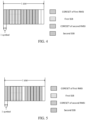
- FIG. 2 exemplarily illustrates one network device and two of UEs.
- the communication system 100 may include a plurality of network devices, and a coverage range of each network device may include other numbers of UEs, which is not limited by the embodiment of the present disclosure.
- the communication system 100 may also include other network entities such as a network controller and a mobile management entity, which is not limited by the embodiment of the present disclosure.
- a device having a communication function in a network/system in the embodiment of the present disclosure may be referred to as a communication device.
- the communication system 100 shown in FIG. 2 is taken as an example.
- the communication device may include a network device 110 and UE 120 which have communication functions.
- the network device 110 and the UE 120 may be the above-mentioned specific devices, and descriptions thereof are omitted here.
- the communication device may also include other devices in the communication system 100, such as other network entities including the network controller, the mobile management entity, and the like, which is not limited by the embodiment of the present disclosure.
- an optional processing flow of the information processing method applied to a terminal device includes the following steps:
- the terminal device receives at most two SSBs sent by a network device in one slot, and detects PDCCHs of RMSI on CORESETs of the RMSI in one-to-one association with the at most two SSBs.
- a first optional schematic diagram of candidate position information of the SSB and candidate position information of the CORESET of the RMSI associated with the SSB within one is shown in FIG. 4 .
- Candidate position information of the at most two SSBs in the one slot includes: a first SSB of the at most two SSBs is located on a third symbol to a sixth symbol in the one slot; and/or, a second SSB of the at most two SSBs is located on a ninth symbol to a twelfth symbol in the one slot.
- candidate position information of the CORESETs of the RMSI in one-to-one association with the at most two SSBs includes: a start symbol of a CORESET of first RMSI associated with the first SSB is located on a first symbol in the slot; and/or, a start symbol of a CORESET of second RMSI associated with the second SSB is located on a seventh symbol in the slot.
- candidate position information of the CORESETs of the RMSI in one-to-one association with the at most two SSBs includes: a start symbol of a CORESET of first RMSI associated with the first SSB is located on a seventh symbol in the slot; and/or, a start symbol of a CORESET of second RMSI associated with the second SSB is located on a first symbol in the slot.
- a time domain length of the CORESET of the first RMSI is configured to occupy one symbol or two symbols by the network device
- a time domain length of the CORESET of the second RMSI is configured to occupy one symbol or two symbols by the network device.
- a second optional schematic diagram of candidate position information of the SSB and candidate position information of the CORESET of the RMSI associated with the SSB within one is shown in FIG. 5 .
- Candidate position information of the at most two SSBs in the one slot includes: a first SSB of the at most two SSBs is located on a third symbol to a sixth symbol in the one slot; and/or, a second SSB of the at most two SSBs is located on a tenth symbol to a thirteenth symbol in the one slot.
- candidate position information of the CORESETs of the RMSI associated with the at most two SSBs includes:
- a start symbol of a CORESET of first RMSI associated with the first SSB is located on a first symbol in the slot; and/or, a start symbol of a CORESET of second RMSI associated with the second SSB is located on an eighth symbol in the slot.
- candidate position information of the CORESETs of the RMSI associated with the at most two SSBs includes: a start symbol of a CORESET of first RMSI associated with the first SSB is located on an eighth symbol in the slot; and/or, a start symbol of a CORESET of second RMSI associated with the second SSB is located on a first symbol in the slot.
- a time domain length of the CORESET of the first RMSI is configured to occupy one symbol or two symbols by the network device
- a time domain length of the CORESET of the second RMSI is configured to occupy one symbol or two symbols by the network device.
- a third optional schematic diagram of candidate position information of the SSB and candidate position information of the CORESET of the RMSI associated with the SSB within one is shown in FIG. 6 .
- Candidate position information of the at most two SSBs in the one slot includes: a first SSB of the at most two SSBs is located on a fourth symbol to a seventh symbol in the one slot; and/or, a second SSB of the at most two SSBs is located on an eleventh symbol to a fourteenth symbol in the one slot.
- candidate position information of the CORESETs of the RMSI in one-to-one association with the at most two SSBs includes: a start symbol of a CORESET of first RMSI associated with the first SSB is located on a first symbol in the slot; and/or, a start symbol of a CORESET of second RMSI associated with the second SSB is located on an eighth symbol in the slot.
- candidate position information of the CORESETs of the RMSI in one-to-one association with the at most two SSBs includes: a start symbol of a CORESET of first RMSI associated with the first SSB is located on an eighth symbol in the slot; and/or, a start symbol of a CORESET of second RMSI associated with the second SSB is located on a first symbol in the slot.
- a time domain length of the CORESET of the RMSI is configured by the network device such that a time domain length of the CORESET of the first RMSI occupies at most three symbols; and/or, a time domain length of the CORESET of the second RMSI The time domain length occupies at most three symbols.
- the terminal can simultaneously receive one SSB and the CORESET of the RMSI associated with the SSB in one slot; the terminal can also simultaneously receive two SSBs and the CORESETs of the two pieces of RMSI in one-to-one correspondence with the two SSBs in one slot.
- the positions of the start symbols of the CORESETs of the two pieces of RMSI are not limited.
- the start symbols of the CORESETs of the two pieces of RMSI are located on the first symbol and the seventh symbol in one slot, respectively, it may be that the CORESET of the first RMSI among the CORESETs of the two pieces of RMSI is located on the first symbol in the slot, the CORESET of the second RMSI among the CORESETs of the two pieces of RMSI is located on the seventh symbol in the slot; it may also be that the CORESET of the second RMSI among the CORESETs of the two pieces of RMSI is located on the first symbol in the slot, the CORESET of the first RMSI among the CORESETs of the two pieces of RMSI is located on the seventh symbol in the slot. It can be understood that the position of the CORESETs of the two pieces of RMSI within one slot are not related to the positions of the SSBs associated with the CORESETs of the two pieces of RMSI.
- the present disclosure is supported to simultaneously transmit/receive two SSBs and the CORESET of the RMSI in one-to-one correspondence with the two SSBs in one slot; in this way, it is conducive to limited use of the time-frequency resources after successful LBT, so that individual SSBs and the CORESET of the RMSI associated with the respective SSB are transmitted/received as a unified NR-U DRS.
- FIG. 7 An optional processing flow of an information processing method applied to a network device provided by an embodiment of the present disclosure is as shown in FIG. 7 , and the information processing method includes:
- the network device determines candidate position information of at most two SSBs and candidate position information of CORESETs of RMSI in one-to-one association with the at most two SSBs in one slot.
- the terminal can simultaneously receive one SSB and detect the PDCCH of the RMSI on the CORESET of the RMSI associated with the SSB in one slot; the terminal can also simultaneously receive two SSBs and detect the PDCCH of the RMSI on the CORESET of the RMSI in one-to-one correspondence with the two SSBs in one slot.
- the positions of the start symbols of the CORESETs of the two pieces of RMSI are not limited.
- the present disclosure is supported to simultaneously transmit/receive two SSBs and the CORESET of the RMSI in one-to-one correspondence with the two SSBs in one slot; in this way, it is conducive to limited use of the time-frequency resources after successful LBT, so that individual SSBs and the CORESET of the RMSI associated with the respective SSB are transmitted/received as a unified NR-U DRS.
- the method further includes: the network device sends the at most two SSBs in one slot, and the PDCCH of the RMSI on the CORESETs of the RMSI in one-to-one association with the at most two SSBs to a terminal device.
- the embodiments of the present disclosure provide a terminal device.
- a schematic diagram of a composition structure of the terminal device 400 is as shown in FIG. 8 , and the terminal device 400 includes: a receiving unit 401, configured to receive at most two SSBs sent by a network device in one slot, and detect PDCCHs of RMSI on CORESETs of the RMSI in one-to-one association with the at most two SSBs.
- candidate position information of the at most two SSBs in the one slot includes: a first SSB of the at most two SSBs is located on a third symbol to a sixth symbol in the one slot; and/or, a second SSB of the at most two SSBs is located on a ninth symbol to a twelfth symbol in the one slot.
- candidate position information of the CORESETs of the RMSI in one-to-one association with the at most two SSBs includes: a start symbol of a CORESET of first RMSI associated with the first SSB is located on a first symbol in the slot; and/or, a start symbol of a CORESET of second RMSI associated with the second SSB is located on a seventh symbol in the slot.
- candidate position information of the CORESETs of the RMSI in one-to-one association with the at most two SSBs includes: a start symbol of a CORESET of first RMSI associated with the first SSB is located on a seventh symbol in the slot; and/or, a start symbol of a CORESET of second RMSI associated with the second SSB is located on a first symbol in the slot.
- a time domain length of the CORESET of the first RMSI occupies at most two symbols; and/or, a time domain length of the CORESET of the second RMSI occupies at most two symbols.
- candidate position information of the at most two SSBs in the one slot includes: a first SSB of the at most two SSBs is located on a third symbol to a sixth symbol in the one slot; and/or, a second SSB of the at most two SSBs is located on a tenth symbol to a thirteenth symbol in the one slot.
- candidate position information of the CORESETs of the RMSI associated with the at most two SSBs includes: a start symbol of a CORESET of first RMSI associated with the first SSB is located on a first symbol in the slot; and/or, a start symbol of a CORESET of second RMSI associated with the second SSB is located on an eighth symbol in the slot.
- candidate position information of the CORESETs of the RMSI associated with the at most two SSBs includes: a start symbol of a CORESET of first RMSI associated with the first SSB is located on an eighth symbol in the slot; and/or, a start symbol of a CORESET of second RMSI associated with the second SSB is located on a first symbol in the slot.
- a time domain length of the CORESET of the first RMSI occupies at most two symbols; and/or, a time domain length of the CORESET of the second RMSI occupies at most two symbols.
- candidate position information of the at most two SSBs in the one slot includes: a first SSB of the at most two SSBs is located on a fourth symbol to a seventh symbol in the one slot; and/or, a second SSB of the at most two SSBs is located on an eleventh symbol to a fourteenth symbol in the one slot.
- candidate position information of the CORESETs of the RMSI in one-to-one association with the at most two SSBs includes: a start symbol of a CORESET of first RMSI associated with the first SSB is located on a first symbol in the slot; and/or, a start symbol of a CORESET of second RMSI associated with the second SSB is located on an eighth symbol in the slot.
- candidate position information of the CORESETs of the RMSI in one-to-one association with the at most two SSBs includes: a start symbol of a CORESET of first RMSI associated with the first SSB is located on an eighth symbol in the slot; and/or, a start symbol of a CORESET of second RMSI associated with the second SSB is located on a first symbol in the slot.
- a time domain length of the CORESET of the RMSI includes: a time domain length of the CORESET of the first RMSI occupies at most three symbols; and/or, a time domain length of the CORESET of the second RMSI occupies at most three symbols symbol.
- the embodiments of the present disclosure also provide a network device.
- a schematic diagram of a composition structure of a network device 500 is as shown in FIG. 9 , and the network device 500 includes:
- candidate position information of the CORESETs of the RMSI in one-to-one association with the at most two SSBs includes: a start symbol of a CORESET of first RMSI associated with the first SSB is located on a first symbol in the slot; and/or, a start symbol of a CORESET of second RMSI associated with the second SSB is located on a seventh symbol in the slot.
- candidate position information of the CORESETs of the RMSI in one-to-one association with the at most two SSBs includes: a start symbol of a CORESET of first RMSI associated with the first SSB is located on a seventh symbol in the slot; and/or, a start symbol of a CORESET of second RMSI associated with the second SSB is located on a first symbol in the slot.
- a time domain length of the CORESET of the first RMSI occupies at most two symbols; and/or, a time domain length of the CORESET of the second RMSI occupies at most two symbols.
- candidate position information of the at most two SSBs in the one slot includes: a first SSB of the at most two SSBs is located on a third symbol to a sixth symbol in the one slot; and/or, a second SSB of the at most two SSBs is located on a tenth symbol to a thirteenth symbol in the one slot.
- candidate position information of the CORESETs of the RMSI associated with the at most two SSBs includes: a start symbol of a CORESET of first RMSI associated with the first SSB is located on a first symbol in the slot; and/or, a start symbol of a CORESET of second RMSI associated with the second SSB is located on an eighth symbol in the slot.
- candidate position information of the CORESETs of the RMSI associated with the at most two SSBs includes: a start symbol of a CORESET of first RMSI associated with the first SSB is located on an eighth symbol in the slot; and/or, a start symbol of a CORESET of second RMSI associated with the second SSB is located on a first symbol in the slot.
- a time domain length of the CORESET of the first RMSI occupies at most two symbols; and/or, a time domain length of the CORESET of the second RMSI occupies at most two symbols.
- candidate position information of the at most two SSBs in the one slot includes: a first SSB of the at most two SSBs is located on a fourth symbol to a seventh symbol in the one slot; and/or, a second SSB of the at most two SSBs is located on an eleventh symbol to a fourteenth symbol in the one slot.
- candidate position information of the CORESETs of the RMSI in one-to-one association with the at most two SSBs includes: a start symbol of a CORESET of first RMSI associated with the first SSB is located on a first symbol in the slot; and/or, a start symbol of a CORESET of second RMSI associated with the second SSB is located on an eighth symbol in the slot.
- candidate position information of the CORESETs of the RMSI in one-to-one association with the at most two SSBs includes: a start symbol of a CORESET of first RMSI associated with the first SSB is located on an eighth symbol in the slot; and/or, a start symbol of a CORESET of second RMSI associated with the second SSB is located on a first symbol in the slot.
- a time domain length of the CORESET of the RMSI includes: a time domain length of the CORESET of the first RMSI occupies at most three symbols; and/or, a time domain length of the CORESET of the second RMSI occupies at most three symbols symbol.
- the network device further includes: a sending unit 502, configured to send the at most two SSBs in one slot, and the PDCCH of the RMSI on the CORESETs of the RMSI in one-to-one association with the at most two SSBs to a terminal device.
- a sending unit 502 configured to send the at most two SSBs in one slot, and the PDCCH of the RMSI on the CORESETs of the RMSI in one-to-one association with the at most two SSBs to a terminal device.
- the embodiments of the present disclosure also provide a terminal device, including a processor and a memory for storing a computer program that is capable of running on the processor, and the processor is configured to execute steps of the power distribution method executed by the terminal device when running the computer program.
- the embodiments of the present disclosure also provide a network device, including a processor and a memory for storing a computer program that is capable of running on the processor, and the processor is configured to execute steps of the power distribution method executed by the network device when running the computer program.
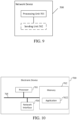
- FIG. 10 is a schematic diagram of a hardware composition structure of an electronic device (network device or terminal device) according to an embodiment of the present disclosure.
- the electronic device 700 includes: at least one processor 701, a memory 702, and at least one network interface 704.
- Various components in the electronic device 700 are coupled together by a bus system 705.
- the bus system 705 is configured to implement connection and communication between these components.
- the bus system 705 also includes a power bus, a control bus, and a status signal bus.
- various buses are marked as the bus system 705 in FIG. 10 .
- the memory 702 may be a volatile memory or a non-volatile memory, or may include both a volatile memory and a non-volatile memory.
- the non-volatile memory may be a read-only memory (ROM), a programmable ROM (PROM), an erasable PROM (EPROM), an electrically EPROM (EEPROM), a ferromagnetic random access memory (FRAM), a flash memory, a ferromagnetic surface memory, optical disk, or an optical disk, or a compact disc read-only memory (CD-ROM); the ferromagnetic surface memory can be a disk memory or a tape memory.
- the volatile memory may be a random access memory (RAM), and is used as an external cache.
- RAM random access memory
- SRAM static random access memory
- SSRAM synchronous static random access memory
- DRAM dynamic random access memory
- SDRAM synchronous dynamic random access memory
- DDRSDRAM double data rate synchronous dynamic random access memory
- ESDRAM enhanced synchronous dynamic random access memory
- SLDRAM synclink dynamic random access memory
- DRRAM direct rambus random access memory
- the method disclosed in the above embodiments of the present disclosure may be applied to the processor 701 or implemented by the processor 701.
- the processor 701 may be an integrated circuit chip, has a signal processing capability, the steps of the foregoing method embodiment may be implemented by using a hardware integrated logic circuit in the processor 701 and/or implemented by using an instruction in a software form.
- the foregoing processor 701 may be a general purpose processor, a digital signal processor (DSP) or another programmable logic device, a transistor logic device, or a discrete hardware component.
- DSP digital signal processor
- the processor 701 may implement or execute the methods, steps, and logical block diagrams disclosed in the embodiments of the present disclosure.
- the general purpose processor may be a microprocessor, or may be any conventional processor, or the like.
- Steps of the methods disclosed with reference to the embodiments of the present disclosure may be directly executed and completed by means of a hardware decoding processor, or may be executed and completed by using a combination of hardware and software modules in the decoding processor.
- the software module may be located in a storage medium, and the storage medium is located in the memory 702, and the processor 701 reads information in the memory 702 and completes the steps in the foregoing method embodiments in combination with hardware of the processor.
- the electronic device 700 may be implemented by one or more application specific integrated circuits (ASIC), DSP, programmable logic devices (PLD), and complex programmable logic devices (CPLD), FPGA, general-purpose processors, controllers, MCUs, MPUs, or other electronic components to implement the aforementioned method.
- ASIC application specific integrated circuits
- DSP digital signal processor
- PLD programmable logic devices
- CPLD complex programmable logic devices
- FPGA general-purpose processors
- controllers MCUs, MPUs, or other electronic components to implement the aforementioned method.
- An embodiment of the present disclosure further provides a computer readable storage medium.
- the computer readable storage medium is configured to store a computer program.
- the computer readable storage medium may be applied to the network device in the embodiments of the present disclosure, and the computer program enables a computer to execute a corresponding procedure implemented by the network device in the methods of the embodiments of the present disclosure.
- the computer program enables a computer to execute a corresponding procedure implemented by the network device in the methods of the embodiments of the present disclosure.
- the computer readable storage medium may be applied to the terminal device in the embodiments of the present disclosure, and the computer program enables the computer to execute a corresponding procedure implemented by the terminal device in the methods of the embodiments of the present disclosure.
- the computer program enables the computer to execute a corresponding procedure implemented by the terminal device in the methods of the embodiments of the present disclosure.
- These computer program instructions can also be stored in a computer-readable memory that can guide a computer or other programmable data processing devices to work in a specific manner, so that the instructions stored in the computer-readable memory generate an article of manufacture including the instruction device, and the instruction device realizes the functions specified in one or more processes in the flowchart and/or one or more blocks in the block diagram.
- These computer program instructions can also be loaded on a computer or other programmable data processing devices, so that a series of operation steps are executed on the computer or other programmable devices to produce computer-implemented processing, so that instructions executed on the computer or other programmable devices provide steps for implementing the functions specified in one or more processes in the flowchart and/or one or more blocks in the block diagram.
Landscapes
- Engineering & Computer Science (AREA)
- Signal Processing (AREA)
- Computer Networks & Wireless Communication (AREA)
- Mobile Radio Communication Systems (AREA)
Claims (6)
- Informationsverarbeitungsverfahren, umfassend:Empfangen (S201), durch eine Endgerätevorrichtung, von zwei Synchronisationssignalblöcken, SSBs, die durch eine Netzwerkvorrichtung in einem Zeitschlitz gesendet werden, und Erfassen von physikalischen Abwärtsstreckensteuerkanälen, PDCCHs, von verbleibenden Mindestsysteminformationen, RMSI, auf Steuerressourcensätzen, CORESETs, der RMSI in Eins-zu-eins-Zuordnung mit den zwei SSBs,dadurch gekennzeichnet, dass:wobei Kandidatenpositionsinformationen der zwei SSBs in dem einen Zeitschlitz Folgendes umfassen: Ein erster SSB der zwei SSBs befindet sich auf einem vierten Symbol bis zu einem siebten Symbol in dem einen Zeitschlitz; und ein zweiter SSB der zwei SSBs befindet sich auf einem elften Symbol bis zu einem vierzehnten Symbol in dem einen Zeitschlitz,wobei eine Zeitdomänenlänge des CORESET der RMSI Folgendes umfasst:Höchstens drei Symbole werden für eine Zeitdomänenlänge des CORESET der ersten RMSI zugewiesen;und/oder höchstens drei Symbole werden für eine Zeitdomänenlänge des CORESET der zweiten RMSI zugewiesen.
- Verfahren nach Anspruch 1, wobei Kandidatenpositionsinformationen der CORESETs der RMSI in Eins-zu-eins-Zuordnung mit den zwei SSBs Folgendes umfassen:Ein Startsymbol eines CORESET der ersten RMSI, die dem ersten SSB zugeordnet ist, befindet sich auf einem ersten Symbol in dem Zeitschlitz, und/oder ein Startsymbol eines CORESET der zweiten RMSI, die dem zweiten SSB zugeordnet ist, befindet sich auf einem achten Symbol in dem Zeitschlitz; und/oderein Startsymbol eines CORESET der ersten RMSI, die dem ersten SSB zugeordnet ist, befindet sich auf einem achten Symbol in dem Zeitschlitz, und/oder ein Startsymbol eines CORESET der zweiten RMSI, die dem zweiten SSB zugeordnet ist, befindet sich auf einem ersten Symbol in dem Zeitschlitz.
- Informationsverarbeitungsverfahren, umfassend:Bestimmen (S301), durch eine Netzwerkvorrichtung, von Kandidatenpositionsinformationen von zwei Synchronisationssignalblöcken, SSBs, und Kandidatenpositionsinformationen von Steuerressourcensätzen, CORESETs, von verbleibenden Mindestsysteminformationen, RMSI, in Eins-zu-eins-Zuordnung mit den zwei SSBs in einem Zeitschlitz, sodass die zwei SSBs und physikalische Abwärtsstreckensteuerkanäle, PDCCHs, der RMSI in den CORESETs der RMSI in Eins-zu-eins-Zuordnung mit den zwei SSBs in einem Zeitschlitz übertragen werden,dadurch gekennzeichnet, dass:wobei Kandidatenpositionsinformationen der zwei SSBs in dem einen Zeitschlitz Folgendes umfassen: Ein erster SSB der zwei SSBs befindet sich auf einem vierten Symbol bis zu einem siebten Symbol in dem einen Zeitschlitz; und ein zweiter SSB der zwei SSBs befindet sich auf einem elften Symbol bis zu einem vierzehnten Symbol in dem einen Zeitschlitz,wobei eine Zeitdomänenlänge des CORESET der RMSI Folgendes umfasst:Höchstens drei Symbole werden für eine Zeitdomänenlänge des CORESET der ersten RMSI zugewiesen;und/oder höchstens drei Symbole werden für eine Zeitdomänenlänge des CORESET der zweiten RMSI zugewiesen.
- Verfahren nach Anspruch 3, wobei Kandidatenpositionsinformationen der CORESETs der RMSI, die den zwei SSBs zugeordnet sind, Folgendes umfassen:Ein Startsymbol eines CORESET der ersten RMSI, die dem ersten SSB zugeordnet ist, befindet sich auf einem ersten Symbol in dem Zeitschlitz, und/oder ein Startsymbol eines CORESET der zweiten RMSI, die dem zweiten SSB zugeordnet ist, befindet sich auf einem achten Symbol in dem Zeitschlitz; und/oderein Startsymbol eines CORESET der ersten RMSI, die dem ersten SSB zugeordnet ist, befindet sich auf einem achten Symbol in dem Zeitschlitz, und/oder ein Startsymbol eines CORESET der zweiten RMSI, die dem zweiten SSB zugeordnet ist, befindet sich auf einem ersten Symbol in dem Zeitschlitz.
- Endgerätevorrichtung (400), umfassend Module, die dazu ausgelegt sind, das Informationsverarbeitungsverfahren nach einem der Ansprüche 1 bis 2 durchzuführen.
- Netzwerkvorrichtung (500), umfassend Module, die dazu ausgelegt sind, das Informationsverarbeitungsverfahren nach einem der Ansprüche 3 bis 4 durchzuführen.
Applications Claiming Priority (1)
| Application Number | Priority Date | Filing Date | Title |
|---|---|---|---|
| PCT/CN2018/108062 WO2020061936A1 (zh) | 2018-09-27 | 2018-09-27 | 一种信息处理方法、设备及存储介质 |
Publications (3)
| Publication Number | Publication Date |
|---|---|
| EP3860016A1 EP3860016A1 (de) | 2021-08-04 |
| EP3860016A4 EP3860016A4 (de) | 2021-11-03 |
| EP3860016B1 true EP3860016B1 (de) | 2025-04-30 |
Family
ID=69950884
Family Applications (1)
| Application Number | Title | Priority Date | Filing Date |
|---|---|---|---|
| EP18935271.9A Active EP3860016B1 (de) | 2018-09-27 | 2018-09-27 | Informationsverarbeitungsverfahren, vorrichtung und speichermedium |
Country Status (5)
| Country | Link |
|---|---|
| US (1) | US11956793B2 (de) |
| EP (1) | EP3860016B1 (de) |
| CN (1) | CN112740599A (de) |
| TW (1) | TW202033019A (de) |
| WO (1) | WO2020061936A1 (de) |
Families Citing this family (3)
| Publication number | Priority date | Publication date | Assignee | Title |
|---|---|---|---|---|
| WO2020087524A1 (zh) * | 2018-11-02 | 2020-05-07 | Oppo广东移动通信有限公司 | 非授权频段上ssb的传输方法和设备 |
| CN113169856A (zh) | 2019-08-30 | 2021-07-23 | Oppo广东移动通信有限公司 | 处理ssb传输和周期性传输之间的冲突的装置和方法 |
| WO2021244413A1 (en) * | 2020-06-02 | 2021-12-09 | Shanghai Langbo Communication Technology Company Limited | Method and device in a node used for wireless communication |
Family Cites Families (10)
| Publication number | Priority date | Publication date | Assignee | Title |
|---|---|---|---|---|
| EP3535940B1 (de) * | 2016-12-07 | 2021-07-21 | LG Electronics Inc. | Verfahren und vorrichtung zur konfiguration des steuerkanals für nr in drahtloskommunikationssystem |
| US11496976B2 (en) * | 2017-03-24 | 2022-11-08 | Telefonaktiebolaget Lm Ericsson (Publ) | Method and device for synchronization in a wireless communication system |
| EP3713327B8 (de) * | 2017-11-14 | 2023-05-10 | Beijing Xiaomi Mobile Software Co., Ltd. | Verfahren zur anzeige der frequenzdomäneninformation eines gemeinsamen steuerressourcensatzes von verbleibenden minimalen systeminformationen |
| JP7148538B2 (ja) * | 2017-11-16 | 2022-10-05 | 株式会社Nttドコモ | 端末、無線通信方法、基地局及びシステム |
| CN108390747B (zh) * | 2018-01-19 | 2021-10-22 | 宇龙计算机通信科技(深圳)有限公司 | 一种同步信号的发送方法和装置 |
| BR112020014813A2 (pt) * | 2018-01-26 | 2020-12-08 | Beijing Xiaomi Mobile Software Co., Ltd. | Método e meio de armazenamento para configurar informação, equipamento de usuário, método e meio de armazenamento para determinar posição de tempo e frequência, e estação base |
| WO2019157725A1 (zh) * | 2018-02-14 | 2019-08-22 | Oppo广东移动通信有限公司 | 一种控制信道的资源确定方法及装置、计算机存储介质 |
| CN108513719B (zh) * | 2018-04-04 | 2020-11-13 | 北京小米移动软件有限公司 | 传输同步广播块的方法及装置 |
| CN108513362B (zh) * | 2018-04-04 | 2022-10-21 | 宇龙计算机通信科技(深圳)有限公司 | 一种信道检测方法、装置及基站 |
| WO2019205088A1 (zh) * | 2018-04-27 | 2019-10-31 | 北京小米移动软件有限公司 | 传输同步广播块和rmsi的相关信息的方法及装置 |
-
2018
- 2018-09-27 WO PCT/CN2018/108062 patent/WO2020061936A1/zh not_active Ceased
- 2018-09-27 EP EP18935271.9A patent/EP3860016B1/de active Active
- 2018-09-27 CN CN201880097698.XA patent/CN112740599A/zh active Pending
-
2019
- 2019-09-26 TW TW108134953A patent/TW202033019A/zh unknown
-
2021
- 2021-03-25 US US17/213,192 patent/US11956793B2/en active Active
Also Published As
| Publication number | Publication date |
|---|---|
| US11956793B2 (en) | 2024-04-09 |
| WO2020061936A1 (zh) | 2020-04-02 |
| EP3860016A1 (de) | 2021-08-04 |
| US20210219274A1 (en) | 2021-07-15 |
| EP3860016A4 (de) | 2021-11-03 |
| CN112740599A (zh) | 2021-04-30 |
| TW202033019A (zh) | 2020-09-01 |
Similar Documents
| Publication | Publication Date | Title |
|---|---|---|
| CN109792660B (zh) | 一种信息指示方法及装置、网络设备、终端设备 | |
| CN114073142B (zh) | 一种资源处理方法、设备及存储介质 | |
| EP3820100B1 (de) | Datenübertragungsverfahren, endgerätevorrichtung und netzwerkvorrichtung | |
| CN109644426B (zh) | 接收信息、发送信息的方法和设备 | |
| US12363714B2 (en) | Method for transmitting control information, electronic device and storage medium | |
| US12520255B2 (en) | Wireless communication method, terminal device and network device | |
| WO2020150957A1 (zh) | 用于非授权频谱的无线通信方法和设备 | |
| US20220046632A1 (en) | Communication method in d2d system, terminal device, and network device | |
| US11956793B2 (en) | Information processing method, device and storage medium | |
| WO2020061946A1 (zh) | 一种信息处理方法、设备及存储介质 | |
| CN110100489B (zh) | 传输上行控制信道的方法、网络设备和终端设备 | |
| AU2018442195A1 (en) | Wireless communication method, transmitting node and receiving node | |
| US12426054B2 (en) | Channel processing method and electronic device | |
| US11856539B2 (en) | Method and device for transmitting downlink control information | |
| WO2020087540A1 (zh) | 一种控制信息的传输方法、设备及存储介质 | |
| EP3869850B1 (de) | Verfahren und vorrichtung zur bestimmung der anzahl von blinddetektionen und endgerät | |
| US11438902B2 (en) | Method for determining slot format, terminal device and network device |
Legal Events
| Date | Code | Title | Description |
|---|---|---|---|
| STAA | Information on the status of an ep patent application or granted ep patent |
Free format text: STATUS: THE INTERNATIONAL PUBLICATION HAS BEEN MADE |
|
| PUAI | Public reference made under article 153(3) epc to a published international application that has entered the european phase |
Free format text: ORIGINAL CODE: 0009012 |
|
| STAA | Information on the status of an ep patent application or granted ep patent |
Free format text: STATUS: REQUEST FOR EXAMINATION WAS MADE |
|
| 17P | Request for examination filed |
Effective date: 20210423 |
|
| AK | Designated contracting states |
Kind code of ref document: A1 Designated state(s): AL AT BE BG CH CY CZ DE DK EE ES FI FR GB GR HR HU IE IS IT LI LT LU LV MC MK MT NL NO PL PT RO RS SE SI SK SM TR |
|
| A4 | Supplementary search report drawn up and despatched |
Effective date: 20211004 |
|
| RIC1 | Information provided on ipc code assigned before grant |
Ipc: H04W 56/00 20090101ALI20210928BHEP Ipc: H04W 74/00 20090101ALI20210928BHEP Ipc: H04W 72/04 20090101ALI20210928BHEP Ipc: H04L 5/00 20060101AFI20210928BHEP |
|
| DAV | Request for validation of the european patent (deleted) | ||
| DAX | Request for extension of the european patent (deleted) | ||
| STAA | Information on the status of an ep patent application or granted ep patent |
Free format text: STATUS: EXAMINATION IS IN PROGRESS |
|
| 17Q | First examination report despatched |
Effective date: 20231006 |
|
| GRAP | Despatch of communication of intention to grant a patent |
Free format text: ORIGINAL CODE: EPIDOSNIGR1 |
|
| STAA | Information on the status of an ep patent application or granted ep patent |
Free format text: STATUS: GRANT OF PATENT IS INTENDED |
|
| INTG | Intention to grant announced |
Effective date: 20250108 |
|
| GRAS | Grant fee paid |
Free format text: ORIGINAL CODE: EPIDOSNIGR3 |
|
| GRAA | (expected) grant |
Free format text: ORIGINAL CODE: 0009210 |
|
| STAA | Information on the status of an ep patent application or granted ep patent |
Free format text: STATUS: THE PATENT HAS BEEN GRANTED |
|
| AK | Designated contracting states |
Kind code of ref document: B1 Designated state(s): AL AT BE BG CH CY CZ DE DK EE ES FI FR GB GR HR HU IE IS IT LI LT LU LV MC MK MT NL NO PL PT RO RS SE SI SK SM TR |
|
| REG | Reference to a national code |
Ref country code: CH Ref legal event code: EP Ref country code: GB Ref legal event code: FG4D |
|
| REG | Reference to a national code |
Ref country code: DE Ref legal event code: R096 Ref document number: 602018081639 Country of ref document: DE |
|
| REG | Reference to a national code |
Ref country code: IE Ref legal event code: FG4D |
|
| REG | Reference to a national code |
Ref country code: NL Ref legal event code: MP Effective date: 20250430 |
|
| REG | Reference to a national code |
Ref country code: AT Ref legal event code: MK05 Ref document number: 1791093 Country of ref document: AT Kind code of ref document: T Effective date: 20250430 |
|
| P01 | Opt-out of the competence of the unified patent court (upc) registered |
Free format text: CASE NUMBER: UPC_APP_5349_3860016/2025 Effective date: 20250829 |
|
| PG25 | Lapsed in a contracting state [announced via postgrant information from national office to epo] |
Ref country code: PT Free format text: LAPSE BECAUSE OF FAILURE TO SUBMIT A TRANSLATION OF THE DESCRIPTION OR TO PAY THE FEE WITHIN THE PRESCRIBED TIME-LIMIT Effective date: 20250901 Ref country code: FI Free format text: LAPSE BECAUSE OF FAILURE TO SUBMIT A TRANSLATION OF THE DESCRIPTION OR TO PAY THE FEE WITHIN THE PRESCRIBED TIME-LIMIT Effective date: 20250430 Ref country code: ES Free format text: LAPSE BECAUSE OF FAILURE TO SUBMIT A TRANSLATION OF THE DESCRIPTION OR TO PAY THE FEE WITHIN THE PRESCRIBED TIME-LIMIT Effective date: 20250430 |
|
| REG | Reference to a national code |
Ref country code: LT Ref legal event code: MG9D |
|
| PG25 | Lapsed in a contracting state [announced via postgrant information from national office to epo] |
Ref country code: NO Free format text: LAPSE BECAUSE OF FAILURE TO SUBMIT A TRANSLATION OF THE DESCRIPTION OR TO PAY THE FEE WITHIN THE PRESCRIBED TIME-LIMIT Effective date: 20250730 Ref country code: GR Free format text: LAPSE BECAUSE OF FAILURE TO SUBMIT A TRANSLATION OF THE DESCRIPTION OR TO PAY THE FEE WITHIN THE PRESCRIBED TIME-LIMIT Effective date: 20250731 |
|
| PG25 | Lapsed in a contracting state [announced via postgrant information from national office to epo] |
Ref country code: PL Free format text: LAPSE BECAUSE OF FAILURE TO SUBMIT A TRANSLATION OF THE DESCRIPTION OR TO PAY THE FEE WITHIN THE PRESCRIBED TIME-LIMIT Effective date: 20250430 Ref country code: NL Free format text: LAPSE BECAUSE OF FAILURE TO SUBMIT A TRANSLATION OF THE DESCRIPTION OR TO PAY THE FEE WITHIN THE PRESCRIBED TIME-LIMIT Effective date: 20250430 |
|
| PG25 | Lapsed in a contracting state [announced via postgrant information from national office to epo] |
Ref country code: BG Free format text: LAPSE BECAUSE OF FAILURE TO SUBMIT A TRANSLATION OF THE DESCRIPTION OR TO PAY THE FEE WITHIN THE PRESCRIBED TIME-LIMIT Effective date: 20250430 |
|
| PGFP | Annual fee paid to national office [announced via postgrant information from national office to epo] |
Ref country code: GB Payment date: 20250915 Year of fee payment: 8 |
|
| PG25 | Lapsed in a contracting state [announced via postgrant information from national office to epo] |
Ref country code: HR Free format text: LAPSE BECAUSE OF FAILURE TO SUBMIT A TRANSLATION OF THE DESCRIPTION OR TO PAY THE FEE WITHIN THE PRESCRIBED TIME-LIMIT Effective date: 20250430 |
|
| PG25 | Lapsed in a contracting state [announced via postgrant information from national office to epo] |
Ref country code: AT Free format text: LAPSE BECAUSE OF FAILURE TO SUBMIT A TRANSLATION OF THE DESCRIPTION OR TO PAY THE FEE WITHIN THE PRESCRIBED TIME-LIMIT Effective date: 20250430 |
|
| PG25 | Lapsed in a contracting state [announced via postgrant information from national office to epo] |
Ref country code: RS Free format text: LAPSE BECAUSE OF FAILURE TO SUBMIT A TRANSLATION OF THE DESCRIPTION OR TO PAY THE FEE WITHIN THE PRESCRIBED TIME-LIMIT Effective date: 20250731 |
|
| PG25 | Lapsed in a contracting state [announced via postgrant information from national office to epo] |
Ref country code: IS Free format text: LAPSE BECAUSE OF FAILURE TO SUBMIT A TRANSLATION OF THE DESCRIPTION OR TO PAY THE FEE WITHIN THE PRESCRIBED TIME-LIMIT Effective date: 20250830 |
|
| PG25 | Lapsed in a contracting state [announced via postgrant information from national office to epo] |
Ref country code: LV Free format text: LAPSE BECAUSE OF FAILURE TO SUBMIT A TRANSLATION OF THE DESCRIPTION OR TO PAY THE FEE WITHIN THE PRESCRIBED TIME-LIMIT Effective date: 20250430 |
|
| PG25 | Lapsed in a contracting state [announced via postgrant information from national office to epo] |
Ref country code: SM Free format text: LAPSE BECAUSE OF FAILURE TO SUBMIT A TRANSLATION OF THE DESCRIPTION OR TO PAY THE FEE WITHIN THE PRESCRIBED TIME-LIMIT Effective date: 20250430 Ref country code: DK Free format text: LAPSE BECAUSE OF FAILURE TO SUBMIT A TRANSLATION OF THE DESCRIPTION OR TO PAY THE FEE WITHIN THE PRESCRIBED TIME-LIMIT Effective date: 20250430 |
|
| PG25 | Lapsed in a contracting state [announced via postgrant information from national office to epo] |
Ref country code: CZ Free format text: LAPSE BECAUSE OF FAILURE TO SUBMIT A TRANSLATION OF THE DESCRIPTION OR TO PAY THE FEE WITHIN THE PRESCRIBED TIME-LIMIT Effective date: 20250430 |
|
| PG25 | Lapsed in a contracting state [announced via postgrant information from national office to epo] |
Ref country code: EE Free format text: LAPSE BECAUSE OF FAILURE TO SUBMIT A TRANSLATION OF THE DESCRIPTION OR TO PAY THE FEE WITHIN THE PRESCRIBED TIME-LIMIT Effective date: 20250430 |
|
| PG25 | Lapsed in a contracting state [announced via postgrant information from national office to epo] |
Ref country code: RO Free format text: LAPSE BECAUSE OF FAILURE TO SUBMIT A TRANSLATION OF THE DESCRIPTION OR TO PAY THE FEE WITHIN THE PRESCRIBED TIME-LIMIT Effective date: 20250430 Ref country code: SK Free format text: LAPSE BECAUSE OF FAILURE TO SUBMIT A TRANSLATION OF THE DESCRIPTION OR TO PAY THE FEE WITHIN THE PRESCRIBED TIME-LIMIT Effective date: 20250430 |
|
| PG25 | Lapsed in a contracting state [announced via postgrant information from national office to epo] |
Ref country code: IT Free format text: LAPSE BECAUSE OF FAILURE TO SUBMIT A TRANSLATION OF THE DESCRIPTION OR TO PAY THE FEE WITHIN THE PRESCRIBED TIME-LIMIT Effective date: 20250430 |
|
| REG | Reference to a national code |
Ref country code: DE Ref legal event code: R097 Ref document number: 602018081639 Country of ref document: DE |
|
| PLBE | No opposition filed within time limit |
Free format text: ORIGINAL CODE: 0009261 |
|
| STAA | Information on the status of an ep patent application or granted ep patent |
Free format text: STATUS: NO OPPOSITION FILED WITHIN TIME LIMIT |
|
| REG | Reference to a national code |
Ref country code: CH Ref legal event code: L10 Free format text: ST27 STATUS EVENT CODE: U-0-0-L10-L00 (AS PROVIDED BY THE NATIONAL OFFICE) Effective date: 20260311 |
|
| 26N | No opposition filed |
Effective date: 20260202 |