EP3859983B1 - Diskontinuierlicher zeit-frequenz-betrieb - Google Patents
Diskontinuierlicher zeit-frequenz-betrieb Download PDFInfo
- Publication number
- EP3859983B1 EP3859983B1 EP20154975.5A EP20154975A EP3859983B1 EP 3859983 B1 EP3859983 B1 EP 3859983B1 EP 20154975 A EP20154975 A EP 20154975A EP 3859983 B1 EP3859983 B1 EP 3859983B1
- Authority
- EP
- European Patent Office
- Prior art keywords
- time domain
- domain symbol
- data values
- tone data
- sets
- Prior art date
- Legal status (The legal status is an assumption and is not a legal conclusion. Google has not performed a legal analysis and makes no representation as to the accuracy of the status listed.)
- Active
Links
Images

Classifications
-
- H—ELECTRICITY
- H04—ELECTRIC COMMUNICATION TECHNIQUE
- H04B—TRANSMISSION
- H04B3/00—Line transmission systems
- H04B3/02—Details
- H04B3/32—Reducing cross-talk, e.g. by compensating
-
- H—ELECTRICITY
- H04—ELECTRIC COMMUNICATION TECHNIQUE
- H04J—MULTIPLEX COMMUNICATION
- H04J1/00—Frequency-division multiplex systems
- H04J1/02—Details
- H04J1/12—Arrangements for reducing cross-talk between channels
-
- H—ELECTRICITY
- H04—ELECTRIC COMMUNICATION TECHNIQUE
- H04J—MULTIPLEX COMMUNICATION
- H04J11/00—Orthogonal multiplex systems, e.g. using WALSH codes
Definitions
- Various example embodiments relate, amongst others, to an apparatus for generating time domain symbols for time synchronized transmission over communication lines.
- a plurality of communication lines connect an access node, sometimes referred to as distribution point unit, DPU, with remote terminal nodes, sometimes referred to as customer premises equipment, CPE.
- DMT discrete multi-tone modulation
- the data intended for provision to a terminal node is first encoded into frequency domain symbols which are multiplexed onto K different frequency sub-carriers, also referred to as tones.
- K frequency domain symbols each corresponding to a different tone, also referred to as tone data values, are then converted to a single time domain symbol for further transmission over the communication line to the respective terminal node.
- Crosstalk between the different communication lines may cause unwanted interference, i.e.
- Crosstalk may be mitigated by pre-compensating the useful communication signals for the respective terminal nodes before transmission.
- the so-obtained pre-compensated communication signals are then jointly transmitted to the respective terminal nodes. This technique is also referred to as vectoring.
- Vectoring is a computationally intensive process for which cost and power increases with the number of communication lines and number of tones.
- a technique for reducing the computational requirements is discontinuous time-frequency operation, DTFO.
- DTFO discontinuous time-frequency operation
- All terminal nodes may use the set of K1 tones for data transmission, while only a single selected terminal node can use the set of K2 tones for data transmission. This way, full vectoring is only required on a subset of tones, i.e., only on K 1 ⁇ K tones, while the data-rate of the selected terminal node can be boosted by also using the set of K2 tones.
- WO2018178399A1 discloses a method and apparatus for transmitting data from a transmitter device to one or more receiver devices connected to the transmitter device via a respective wire connection, the transmitter device being operable to transmit signals onto the wire connections and a further wire connection at different tones, the method comprising: for each tone, allocating signals transmitted on the further wire connection as supporting signals for a particular wire connection, and measuring electromagnetic coupling between the further wire connection and that particular wire connection; using the measurements, determining a power allocation for transmitting a supporting signal on the further wire connection; for one or more of the tones: transmitting a signal onto the particular wire connection, and transmitting a supporting signal onto the further wire connection at the determined transmission power, thereby to cause crosstalk interference in the particular wire connection.
- Embodiments according to the present invention are set out in the appended independent and dependent claims. Amongst others, it is an object of embodiments of the invention to provide a DTFO implementation that provides a high data rate while keeping the needed computational resources low.
- the present application discloses an apparatus comprising means for performing:
- the second time domain symbol is thus not only added to the first time domain symbol for the selected terminal node but also to at least one of the first time domain symbols for the other terminal nodes.
- a time domain shaping of the transmit symbols in the frequency band of the K 2 tones is achieved by the weighting operation. This shaping is further independent from the frequency band represented by the other K 1 tones.
- a time domain beamforming to the selected terminal node is achieved within the frequency band represented by the K 2 tones which boosts the data-rate of the selected terminal node without further affecting the other terminal nodes.
- all the above steps are performed digitally, i.e. in the digital domain before a further digital to analogue conversion.
- the time domain beamforming requires only memory for up to N 2 weighting coefficients for the K 2 tones, while (frequency domain) full vectoring requires memory for up to K 2 ⁇ N 2 coefficients for the K 2 tones.
- the adding in a weighted manner may be performed by adding or subtracting the second time domain symbol from the first time domain symbols.
- the amount of adding or subtracting i.e. the weighted manner, may relate to applying a discrete or continuous phase shift, or to applying a multiplication with a single real-valued or complex-valued scalar.
- the adding in a weighted manner may be performed according to weighting coefficients.
- the means are further configured for selecting the selected one of the N terminal nodes based on throughput requirements. For example, a terminal node with a highest throughput requirement may be selected.
- the means can be further configured for selecting the weighting coefficients based on the selected one of the N terminal nodes. In other words, depending on the selected terminal node, a different set of weighting coefficients is selected.
- Sets of weighting coefficients associated with the respective terminal nodes may for example be stored in a lookup table and selected therefrom. Alternatively, weighting coefficients may be determined according to a predetermined ruleset or derived from a subset of common weighting coefficients.
- weighting coefficients are selected from one of the groups comprising ⁇ 0; 1 ⁇ ; ⁇ 1; -1 ⁇ ; or ⁇ 1 ⁇ .
- the second time domain symbol may be added to a first time domain symbol or subtracted from one or more of the first time domain symbols.
- all weighting coefficients may be equal, for example equal to 1. This way, the weighting coefficients are the same for all selected terminal nodes.
- the second time domain symbol is complex and the means are further configured for performing adding according to complex weighting coefficients.
- the conversion of the K 2 tone data values from the frequency to the time domain is performed by complex numbers.
- the weighting coefficients may also be complex thereby achieving a greater flexibility in weighting.
- the weighting coefficients may be selected such that a rotation of the second time domain symbol is performed in the complex plane.
- the complex weighting coefficients may for example be selected from the group comprising 1, -1, j and -j.
- the means are further configured for calculating the N sets of first time domain symbols by performing a frequency to time domain conversion and an upsampling.
- K 1 tone data values are only a subset of the tones that are included in the transmitted time domain symbol, there is no need to perform a full resolution frequency to time domain conversion, i.e., from K 1 tone data values to 2(K 1 + K 2 ) time domain values.
- the calculation of this conversion is therefore simplified by first performing a conversion with an accuracy according to the K 1 tone data values, resulting into 2K 1 time domain symbols, followed by an upsampling with factor (K 1 + K 2 )/ K 1 , resulting into the final 2(K 1 + K 2 ) time domain values.
- the means are further configured for adding the second time domain symbol in a weighted manner by performing a bit shifting operation on the second time domain symbol, by performing a sign switching operation on the second time domain symbol, and/or by performing a swapping between a real and imaginary component of the second time domain symbol such that a weighting is achieved and adding the shifted, sign switched, and/or swapped second time domain symbol to the respective one of the first time domain symbols.
- Digital time domain values may be weighted by a bit shifting operation. For example, for complex weighting coefficients, a weighting by 1, -1, j and -j may be achieved by such bit shifting operations.
- the means comprises at least one processor; and at least one memory including computer program code, the at least one memory and computer program code configured to, with the at least one processor, cause the performance of the apparatus.
- the application discloses a second apparatus comprising means for performing:
- the present application relates to an access node for a telecommunication network comprising the apparatus according to the first and/or second example aspect.
- the present application relates to a method comprising the steps of:
- the present application relates to a computer program product comprising computer-executable instructions for causing an apparatus to perform at least the following:
- Example embodiments of the present disclosure relate to the calculation of time domain symbols from tone data values for further transmission onto communication lines of a telecommunication network.
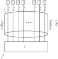
- Fig. 1 shows an example embodiment of such a telecommunication network 100 wherein an access node 120 connects to a plurality of N terminal nodes 111 to 117 over respective communication lines 131 to 137. Terminal nodes 111 to 117 may be located at a client side near the customer premises. Network communication from the access node towards the terminal nodes 111 to 117 is also referred to as downstream, DS, communication 141. Network communication from the terminal nodes 111 to 117 towards the access node 120 is also referred to as upstream, US, communication 142.
- Telecommunication network 100 uses discrete multi-tone modulation (DMT), to first encode digital data into frequency domain symbols which are multiplexed onto different frequency sub-carriers or tones. These frequency domain symbols each corresponding to a different tone, also referred to as tone data values, are then converted to a time domain symbol for further transmission over a respective one of the communication lines 131-137 to a respective one of terminal nodes 111-117.
- DMT discrete multi-tone modulation
- telecommunication network 100 may be referred to as a digital subscriber line, abbreviated by DSL, telecommunication network.
- Crosstalk channels between the different communication lines 131-137 may be present, because, for example, different lines are bundled together in a cable bundle or binder 130 over at least part of the trajectory between the access node 120 and terminal nodes 111-117.
- the crosstalk channels cause unwanted interference, i.e. a time domain symbol transmitted from the access node 120 to one of the terminal nodes 111-117 may be disturbed by other time domain symbols transmitted from the access node 120 to the other terminal nodes. Because of this, the time domain symbol received at a terminal node will also comprise portions of the other time domain symbols.
- Such interference is also referred to as far end crosstalk, FEXT.
- Crosstalk may be mitigated by pre-compensating the communication signals for the respective terminal nodes before transmission by the anticipated crosstalk. The so-obtained pre-compensated communication signals are then jointly transmitted to the respective terminal nodes. This technique is also referred to as vectoring.
- Vectoring is a computationally intensive process for which cost and power increases with the number of communication lines and number of tones.
- One technique for reducing the computational requirements is discontinuous time-frequency operation, DTFO.
- DTFO discontinuous time-frequency operation
- All terminal nodes 111-117 may use the set of K1 tones for data transmission, whereas only a selected one of the terminal nodes 111-117 can use the set of K2 tones for data transmission. This way, full vectoring is only required on a subset of tones, i.e., only on K 1 ⁇ K tones, while the data-rate of the selected terminal node can be boosted by also using the set of K2 tones.
- Embodiments according to the present disclosure may be used in telecommunication systems operating according to telecommunication protocols supporting DTFO, for example according to the recommendations defined by the ITU-T project G.mgfast.
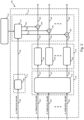
- Fig. 2 shows example embodiment of an apparatus 200 for calculating N time domain symbols 229, 249... 269 from tone data for transmission onto N communication lines.
- apparatus 200 may be included in an access node 120.
- apparatus 200 comprises several depicted functional blocks, hereafter also described as "circuitry". In other embodiments all functions of the apparatus can all be performed by one single processor, or other combinations of functional units performed by e.g. co-operating processing modules.
- the apparatus comprises means (217, 218, 215, 212 ) for receiving N sets of K1 tone data values, for receiving a set of K2 tone data values, for pre-compensating N sets of K 1 tone data values for crosstalk between N communication lines, calculating from the pre-compensated N sets of K 1 tone data values N sets of first time domain symbols, calculating a second time domain symbol from the set of K 2 tones values, adding the second time domain symbol in a weighted manner to the first time domain symbols such that the second time domain symbol is added to the first time domain symbol for the selected terminal node and to at least one other of the first time domain symbols for the respective other terminal nodes, and providing the N time domain communication symbols to an output of the apparatus.
- the embodiment of Fig. 2 comprises a further circuitry 210 configured to pre-compensate N sets of K 1 tone data values 220, 240, 260 for crosstalk between the N communication lines.
- the N sets of K 1 tone data values relate to respective N terminal nodes connected to the N communication lines in a digital communication system, e.g. nodes 111-117 of telecommunication system 100.
- the K 2 other tones are reserved for a selected one of the terminal nodes.
- apparatus 200 also receives a single set of K 2 tone data values 280 for the selected one of the N terminal nodes.
- Each tone value may be the result of a preceding bit loading operation during which a certain amount of data bits are loaded onto the respective tone.
- the number of data bits that are loaded onto a certain tone may be dependent on the channel conditions of the communication line.
- the number of bits that are loaded onto a certain tone may also be the same for all K 1 and/or K 2 tone data values.
- a tone value may be represented by an in-phase, I, and quadrature, Q, component. Each component may then be digitally represented by a binary value.
- the K 1 tone data values may be associated with a first frequency band B 1 available in a communication channel between the access node and respective terminal nodes.
- the K 2 tone data values may be associated with a second other frequency band B 2 available in this communication channel.
- the first frequency band B 1 may be lower than this second frequency band B 2 , i.e. the first frequency band corresponds to a lower band and the second frequency band to a higher band.
- Circuitry 210 calculates N sets of K 1 pre-compensated tone data values 221, 241... 261 from the N sets of K1 tones values 220, 240... 260.
- Apparatus 200 further comprises a circuitry 215 for converting the N sets of K1 pre-compensated tone data values 221, 241... 261 to respective N sets of digital time domain symbols 225, 245... 265.
- apparatus 200 comprises a circuitry 283 for converting the single set of K2 tone data values 280 into a single digital time domain symbol 284.
- a digital time domain symbol is a consecutive series of digital values representing a time-varying communication signal that is to be transmitted onto one of the communication lines.
- Apparatus 200 further comprises a circuitry 212 that is configured to add the time domain signal 284 to the respective N time domain symbols 225, 245... 265 in a weighted manner.
- a weighted manner may be understood as that the circuitry 212 is further configured to i) add the time domain symbol 284 to the one of the time domain symbols 225, 245... 265 that pertains to same terminal node, i.e. the terminal node for which the data bits loaded onto the K 2 tone data values is destined; and to ii) add the time domain symbol 284 to at least one other of the time domain symbols 225, 245... 265.
- no addition may be performed at all, i.e. steps i) and ii) are skipped.
- circuitry 212 may further comprise N adder circuitries 226, 246... 266 for adding N weighted time domain symbols 230, 250... 270 to the respective N time domain symbols 225, 245... 265. Circuitry 212 then further comprises a weighting circuitry 213 that is configured to weight the time domain symbol 284 according to N weighting coefficients thereby producing the N weighted time domain symbols 230, 250... 270.
- the so-obtained N digital time domain symbols 229, 249... 269 may then be further processed in a transmission pipeline for transmission onto N respective communication lines to the N respective terminal nodes.
- the circuitry 212 has the effect that a beamforming effect is achieved towards the selected terminal node within the frequency band corresponding to the K 2 tone data values.
- the pre-compensating circuitry 210 and conversion circuitries 222, 242... 262 are independent from the signal 284, i.e. these circuitries' processing requirements are only based on the K 1 tone data values.
- the weighting coefficients used by circuitry 213 may be different for each selected terminal node, i.e. for each selected terminal node a different set of N weighting coefficients are needed. These different sets may be stored locally in circuitry 213, for example in a lookup-table wherein circuitry 213 retrieves the set of N applicable weighting coefficients based on an identification of the selected terminal node.
- the weighting circuitries may also be directly provided by another circuitry 216. Or, this circuitry 216 may update the weighting coefficients stored in the lookup-table from time to time, e.g. when the weighting coefficients have changed.
- the weighting coefficients may further be determined by circuitry 216 by globally optimizing the coefficients for a maximum data throughput for each of the selected terminal nodes.
- this circuitry is depicted as not forming part of the apparatus 200. In other embodiments this circuitry can be part of the apparatus.
- a locally-optimal approach may be followed wherein the best coefficient is determined for one line while keeping the other coefficients constant.
- the circuitry 216 proceeds to a next iteration wherein the best coefficient is determined for a next communication line.
- the circuitry may repeat such iteration several times over all communication lines until a convergence is reached.
- circuitry 216 may correspond to a vectoring control entity, VCE, which is also not part of apparatus 200.
- VCE vectoring control entity
- Such a vector controlling entity may be configured to determine the vectoring coefficients for use in circuitry 210 for the pre-compensation of the tone data values 220, 240... 260. These vectoring coefficients may be derived from a channel estimation, i.e. an estimation of cross-talk channels between the N communication lines for the K 1 tones.
- Such vectoring control entity receives performance measurements from the remote terminal nodes for deriving the vectoring coefficients.
- the VCE may also retrieve performance measurements on the K 2 tones from the selected terminal node.
- the VCE may also derive the weighting coefficients from channel measurements on the K 2 tones of the communication lines.
- Determining the selected terminal node from the N terminal nodes may be done by the dynamic resource allocation (DRA) component and may be based on different metrics such as the throughput requirements of the terminal nodes.
- the node with the highest throughput requirement may then be selected as the selected node and have its data-rate boosted.
- Throughput requirements may be further based on physical metrics such as the actual instantaneous throughput or a throughput demand from the terminal nodes.
- Throughput requirements may also be based on economic metrics such as a subscription model wherein users may pay extra for having their data rate boosted. Selection of the selected terminal node may vary in time, for example on a symbol by symbol basis, such that several terminal node may benefit from a boosted data rate.
- Circuitry 210 is further embodied as an N ⁇ N vectoring processor 310 for pre-compensating the N sets of K 1 tone data values 320, 340... 360 for crosstalk thereby obtaining the N sets of K1 pre-compensated tone data values 321, 341... 361.
- Frequency to time domain conversion circuitries 222, 242... 262 are further embodied by a respective first circuitry 322, 342... 362 that applies a 2 times K 1 point inverse fast Fourier transform, IFFT, to obtain respective time domain symbols 323, 343... 363.
- circuitry 300 comprises an IFFT circuitry 383 as further embodiment of circuitry 283.
- IFFT circuitry 383 is further configured to calculate a 2 times K point IFFT on 2K input values, which are formed as follows:
- weighting coefficients may be selected from the set ⁇ 0, 1 ⁇ , ⁇ 0, 1, -1 ⁇ or even all have a value 1. In the last example, the coefficients do not need to be changed upon change of the selected terminal node.
- the coefficients may also have a real scalar value thereby achieving a scaling of the time domain symbol 284 in circuitry 213 by performing a multiplication with the respective coefficients in circuitry 213.
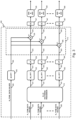
- Circuitry 210 is further embodied as an N ⁇ N vectoring processor 410 for pre-compensating the N sets of K 1 tone data values 420, 440... 460 for crosstalk thereby obtaining the N sets of K1 pre-compensated tone data values 421, 441... 461.
- Frequency to time domain conversion circuitries 222, 242... 262 are further embodied by a respective first circuitry 422, 442... 462 that applies a 2 times K 1 point inverse fast Fourier transform, IFFT, including a mirror copy of the K 1 pre-compensated tone data values, to obtain respective time domain symbols 423, 443... 463.
- Circuitry 400 further comprises a complex IFFT circuitry 483 as further embodiment of circuitry 283.
- IFFT circuitry 483 is further configured to calculate a 2 times K point complex IFFT from the K 2 tone data values 480 thereby obtaining the time domain symbol 484 having 2 times K, 2K, complex time values. i.e. time values represented by complex numbers.
- Circuitry 413 then applies complex weighting coefficients to the complex time domain symbol 484.
- the so-obtained weighted complex time domain symbols values are then converted to real values by taking two times the real component of these complex values.
- the resulting weighted real time domain symbols 430, 450... 470 are then added to the respective time domain symbols 425, 445, 465 thereby obtaining the output time domain symbols 429, 449... 469.
- These time domain symbols may then be further processed by further circuitries of the transmission pipeline, e.g. by adding a cyclic extension by respective circuitries 427, 447... 467, and by digital and analogue front ends, DFEs and AFEs, 428, 448... 468.
- IFFT circuitry 483 calculates complex-valued time-domain symbols 484. According to an embodiment, this is done by discarding the mirror copy of the complex-valued tone data values 480.
- IFFT circuitry 483 calculates complex-valued time-domain symbols 484. According to an embodiment, this is done by discarding the mirror copy of the complex-valued tone data values 480.
- circuitry as well as “means” may refer to one or more or all of the following:
- circuitry also covers an implementation of merely a hardware circuit or processor (or multiple processors) or portion of a hardware circuit or processor and its (or their) accompanying software and/or firmware.
- circuitry also covers, for example and if applicable to the particular claim element, a baseband integrated circuit or processor integrated circuit for a mobile device or a similar integrated circuit in a server, a cellular network device, or other computing or network device.
- top, bottom, over, under, and the like are introduced for descriptive purposes and not necessarily to denote relative positions. It is to be understood that the terms so used are interchangeable under appropriate circumstances and embodiments of the invention are capable of operating according to the present invention in other sequences, or in orientations different from the one(s) described or illustrated above.
Landscapes
- Engineering & Computer Science (AREA)
- Computer Networks & Wireless Communication (AREA)
- Signal Processing (AREA)
- Cable Transmission Systems, Equalization Of Radio And Reduction Of Echo (AREA)
- Telephonic Communication Services (AREA)
Claims (15)
- Vorrichtung (100), die Mittel (200, 300, 400) zum Durchführen von Folgendem umfasst:- Vorkompensieren (210, 310, 410) von N Sätzen von K1 Tondatenwerten (220, 240, 260) für ein Übersprechen zwischen N Kommunikationsleitungen (131-137); wobei die N Sätze von K1 Tondatenwerten zu jeweiligen N Endgeräteknoten (111-117) eines digitalen Kommunikationssystems gehören;- Berechnen (215, 322, 324, 422, 424) N Sätze von ersten Zeitdomänensymbolen (225, 325, 425) aus den vorkompensierten N Sätzen von K1 Tondatenwerten (221, 321, 421);- Berechnen (283, 383, 483,) eines zweiten Zeitdomänensymbols (284, 384, 484) aus einem Satz von K2 Tondatenwerten (280, 380, 480); wobei die K2 Tondatenwerte zu einem ausgewählten der N Endgeräteknoten gehören;- Hinzufügen (212, 312, 412) des zweiten Zeitdomänensymbols in einer gewichteten Weise zu den ersten Zeitdomänensymbolen, derart, dass das zweite Zeitdomänensymbol für den ausgewählten Endgeräteknoten zum ersten Zeitdomänensymbol und für einen jeweiligen anderen Endgeräteknoten zu dem mindestens einen anderen der ersten Zeitdomänensymbole hinzugefügt wird.
- Vorrichtung (100) nach Anspruch 1, wobei die Mittel ferner zum Durchführen des Hinzufügens gemäß Gewichtungskoeffizienten ausgelegt sind.
- Vorrichtung (100) nach Anspruch 2, wobei die Mittel ferner zum Auswählen der Gewichtungskoeffizienten auf Basis des ausgewählten einen der N Endgeräteknoten ausgelegt sind.
- Vorrichtung (100) nach Anspruch 2, wobei die Mittel ferner zum Auswählen des ausgewählten einen der N Endgeräteknoten auf Basis von Durchsatzanforderungen ausgelegt sind.
- Vorrichtung (100) nach einem der Ansprüche 2 bis 4, wobei die Mittel ferner zum Auswählen der Gewichtungskoeffizienten aus einem der Gruppe ausgelegt sind, die Folgendes umfasst:- {0; 1};- {1; -1}; oder- {1}.
- Vorrichtung (100) nach einem der Ansprüche 2 bis 5, wobei alle Gewichtungskoeffizienten gleich sind; vorzugsweise 1.
- Vorrichtung (100) nach einem der Ansprüche 2 bis 6, wobei das Zeitdomänensymbol (480) komplex ist und die Mittel ferner zum Durchführen des Hinzufügens (413) gemäß komplexen Gewichtungskoeffizienten ausgelegt sind.
- Vorrichtung (100) nach Anspruch 7, wobei die Mittel ferner zum Auswählen von komplexen Gewichtungskoeffizienten aus einer Gruppe von Zahlen ausgelegt sind, die 1, -1, j und -j umfassen.
- Vorrichtung (100) nach Anspruch 8, wobei die Mittel ferner dazu ausgelegt sind, komplexe Gewichtungskoeffizienten auszuwählen, derart, dass eine Drehung des zweiten Zeitdomänensymbols in der komplexen Ebene durchgeführt wird.
- Vorrichtung (100) nach einem der vorhergehenden Ansprüche, wobei die Mittel ferner zum Berechnen der N Sätze von ersten Zeitdomänensymbolen durch Durchführen einer Frequenz-zu-Zeitdomäne-Umwandlung (322, 422) und einem Upsampling (324, 424) ausgelegt sind.
- Vorrichtung (100) nach einem der vorhergehenden Ansprüche, wobei die Mittel ferner dazu ausgelegt sind, durch Durchführen einer Bitverschiebungsoperation am zweiten Zeitdomänensymbol, durch Durchführen einer Vorzeichenumschaltoperation am zweiten Zeitdomänensymbol und/oder durch Durchführen eines Vertauschens zwischen einer realen und einer imaginären Komponente des zweiten Zeitdomänensymbols das Hinzufügen (212, 412) des zweiten Zeitdomänensymbols in einer gewichteten Weise, derart, dass eine Gewichtung erreicht wird, und das Hinzufügen des verschobenen, des vorzeichenumgeschalteten und/oder des vertauschten zweiten Zeitdomänensymbols zum jeweiligen der ersten Zeitdomänensymbole durchzuführen.
- Vorrichtung nach einem der vorhergehenden Ansprüche 1 bis 11, wobei die Mittel mindestens einen Prozessor und mindestens einen Speicher, der Computerprogrammcode beinhaltet, umfassen, wobei der mindestens eine Speicher und der Computerprogrammcode dazu ausgelegt sind, mit dem mindestens einen Prozessor die Durchführung der Vorrichtung zu veranlassen.
- Zugangsknoten (100) für ein Telekommunikationsnetzwerk, der die Vorrichtung nach einem der Ansprüche 1 bis 12 umfasst.
- Verfahren, das die folgenden Schritte umfasst:- Vorkompensieren (210, 310, 410) von N Sätzen von K1 Tondatenwerten (220, 240, 260) für ein Übersprechen zwischen N Kommunikationsleitungen (131-137); wobei die N Sätze von K1 Tondatenwerten zu jeweiligen N Endgeräteknoten (111, 117) eines digitalen Kommunikationssystems gehören;- Berechnen (215, 322, 324, 422, 424) N Sätze von ersten Zeitdomänensymbolen (225, 325, 425) aus den vorkompensierten N Sätzen von K1 Tondatenwerten (221, 321, 421);- Berechnen (283, 383, 483,) eines zweiten Zeitdomänensymbols (284, 384, 484) aus einem Satz von K2 Tonwerten (280, 380, 480); wobei die K2 Tondatenwerte zu einem ausgewählten der N Endgeräteknoten gehören;- Hinzufügen (212, 312, 412) des zweiten Zeitdomänensymbols in einer gewichteten Weise zu den ersten Zeitdomänensymbolen, derart, dass das zweite Zeitdomänensymbol für den ausgewählten Endgeräteknoten zum ersten Zeitdomänensymbol und für einen jeweiligen anderen Endgeräteknoten zu dem mindestens einen anderen der ersten Zeitdomänensymbole hinzugefügt wird.
- Computerprogrammprodukt, das computerausführnare Anweisungen zum Veranlassen einer Vorrichtung, mindestens Folgendes durchzuführen, umfasst:- Vorkompensieren (210, 310, 410) von N Sätzen von K1 Tondatenwerten (220, 240, 260) für ein Übersprechen zwischen N Kommunikationsleitungen (131-137); wobei die N Sätze von K1 Tondatenwerten zu jeweiligen N Endgeräteknoten (111, 117) eines digitalen Kommunikationssystems gehören;- Berechnen (215, 322, 324, 422, 424) N Sätze von ersten Zeitdomänensymbolen (225, 325, 425) aus den vorkompensierten N Sätzen von K1 Tondatenwerten (221, 321, 421);- Berechnen (283, 383, 483,) eines zweiten Zeitdomänensymbols (284, 384, 484) aus einem Satz von K2 Tonwerten (280, 380, 480); wobei die K2 Tondatenwerte zu einem ausgewählten der N Endgeräteknoten gehören;- Hinzufügen (212, 312, 412) des zweiten Zeitdomänensymbols in einer gewichteten Weise zu den ersten Zeitdomänensymbolen, derart, dass das zweite Zeitdomänensymbol für den ausgewählten Endgeräteknoten zum ersten Zeitdomänensymbol und für einen jeweiligen anderen Endgeräteknoten zu dem mindestens einen anderen der ersten Zeitdomänensymbole hinzugefügt wird.
Priority Applications (2)
| Application Number | Priority Date | Filing Date | Title |
|---|---|---|---|
| EP20154975.5A EP3859983B1 (de) | 2020-01-31 | 2020-01-31 | Diskontinuierlicher zeit-frequenz-betrieb |
| US17/142,994 US11909510B2 (en) | 2020-01-31 | 2021-01-06 | Discontinuous time-frequency operation |
Applications Claiming Priority (1)
| Application Number | Priority Date | Filing Date | Title |
|---|---|---|---|
| EP20154975.5A EP3859983B1 (de) | 2020-01-31 | 2020-01-31 | Diskontinuierlicher zeit-frequenz-betrieb |
Publications (2)
| Publication Number | Publication Date |
|---|---|
| EP3859983A1 EP3859983A1 (de) | 2021-08-04 |
| EP3859983B1 true EP3859983B1 (de) | 2025-02-19 |
Family
ID=69423229
Family Applications (1)
| Application Number | Title | Priority Date | Filing Date |
|---|---|---|---|
| EP20154975.5A Active EP3859983B1 (de) | 2020-01-31 | 2020-01-31 | Diskontinuierlicher zeit-frequenz-betrieb |
Country Status (2)
| Country | Link |
|---|---|
| US (1) | US11909510B2 (de) |
| EP (1) | EP3859983B1 (de) |
Families Citing this family (2)
| Publication number | Priority date | Publication date | Assignee | Title |
|---|---|---|---|---|
| US11689399B2 (en) * | 2020-01-17 | 2023-06-27 | Intel Corporation | Apparatus, method and non-transitory, computer readable storage media for transmitting and receiving discontinuous time-frequency operation signals in a communication network |
| CN115883306A (zh) * | 2021-09-29 | 2023-03-31 | 中兴通讯股份有限公司 | 数据传输方法、数据调制方法、电子设备和存储介质 |
Family Cites Families (4)
| Publication number | Priority date | Publication date | Assignee | Title |
|---|---|---|---|---|
| AU2008216698B2 (en) * | 2007-02-12 | 2011-06-23 | Mushroom Networks Inc. | Access line bonding and splitting methods and apparatus |
| US10097236B2 (en) * | 2015-03-02 | 2018-10-09 | British Telecommunication Public Limited Company | Method and apparatus for transmitting data in differential and phantom mode in vectoring DSL |
| CN107438987B (zh) * | 2015-03-31 | 2020-10-23 | 英国电讯有限公司 | 在发送器与接收器之间发送数据的方法和系统以及收发器 |
| EP3577890A1 (de) * | 2017-03-31 | 2019-12-11 | British Telecommunications Public Limited Company | Verfahren und vorrichtung zur übertragung von signalen über drahtverbindungen |
-
2020
- 2020-01-31 EP EP20154975.5A patent/EP3859983B1/de active Active
-
2021
- 2021-01-06 US US17/142,994 patent/US11909510B2/en active Active
Also Published As
| Publication number | Publication date |
|---|---|
| EP3859983A1 (de) | 2021-08-04 |
| US11909510B2 (en) | 2024-02-20 |
| US20210242952A1 (en) | 2021-08-05 |
Similar Documents
| Publication | Publication Date | Title |
|---|---|---|
| CN102301612B (zh) | 矢量传输中的串扰系数更新 | |
| US8532204B2 (en) | Peak-to-average power ratio (PAR) reduction based on active-set tone reservation | |
| US7623578B2 (en) | Time domain equalization using frequency domain operations | |
| US5631610A (en) | Single side-band modulation system for use in digitally implemented multicarrier transmission systems | |
| US20020094049A1 (en) | Frame synchronization in multicarrier transmission systems | |
| CN103795659B (zh) | 信道估计 | |
| US8717863B2 (en) | Method and apparatus for vectored data transmission | |
| KR20090042990A (ko) | xDSL 시스템에서의 MIMO 프리코딩을 위한 시스템 및 방법 | |
| EP2489133B1 (de) | Verfahren und vorrichtung für gerichtete datenübertragung | |
| US7822131B2 (en) | Reducing a peak-to-average ratio of a signal | |
| US20080159421A1 (en) | Reducing a peak-to-average ratio of a signal using filtering | |
| JP7204950B2 (ja) | チャネル及び位相雑音の同時推定のための巡回パイロットシーケンス | |
| EP1314260B1 (de) | Frequenzbereichechountedrückung | |
| KR20110050641A (ko) | 이산 멀티-톤(dmt) 누화 제거를 위한 방법 및 장치 | |
| US11909510B2 (en) | Discontinuous time-frequency operation | |
| US8126042B2 (en) | FEXT estimation and signaling in vector transmission | |
| CN102224717B (zh) | xDSL系统中新加入线对的激活方法及装置、xDSL系统 | |
| US8559292B2 (en) | Determining of coupling coefficients in a vector transmission system | |
| EP1420557B1 (de) | Kombinierte Entzerrung für einen DMT-Empfänger | |
| US9780830B2 (en) | Fast crosstalk limitation between modems | |
| CN101765983A (zh) | 处理信道的方法和装置以及包括该装置的通信系统 | |
| US7126997B2 (en) | Multicarrier receiver | |
| JP2003124901A (ja) | 互いに異なった帯域幅を有する受信機と送信機を備える通信システムを初期設定する方法 | |
| CN101610103B (zh) | 一种信道估计方法、装置和系统 | |
| WO2006085502A1 (ja) | 有線通信におけるダイバーシチ受信方法及び受信装置 |
Legal Events
| Date | Code | Title | Description |
|---|---|---|---|
| PUAI | Public reference made under article 153(3) epc to a published international application that has entered the european phase |
Free format text: ORIGINAL CODE: 0009012 |
|
| STAA | Information on the status of an ep patent application or granted ep patent |
Free format text: STATUS: THE APPLICATION HAS BEEN PUBLISHED |
|
| AK | Designated contracting states |
Kind code of ref document: A1 Designated state(s): AL AT BE BG CH CY CZ DE DK EE ES FI FR GB GR HR HU IE IS IT LI LT LU LV MC MK MT NL NO PL PT RO RS SE SI SK SM TR |
|
| STAA | Information on the status of an ep patent application or granted ep patent |
Free format text: STATUS: REQUEST FOR EXAMINATION WAS MADE |
|
| 17P | Request for examination filed |
Effective date: 20220204 |
|
| RBV | Designated contracting states (corrected) |
Designated state(s): AL AT BE BG CH CY CZ DE DK EE ES FI FR GB GR HR HU IE IS IT LI LT LU LV MC MK MT NL NO PL PT RO RS SE SI SK SM TR |
|
| GRAP | Despatch of communication of intention to grant a patent |
Free format text: ORIGINAL CODE: EPIDOSNIGR1 |
|
| STAA | Information on the status of an ep patent application or granted ep patent |
Free format text: STATUS: GRANT OF PATENT IS INTENDED |
|
| INTG | Intention to grant announced |
Effective date: 20240423 |
|
| GRAJ | Information related to disapproval of communication of intention to grant by the applicant or resumption of examination proceedings by the epo deleted |
Free format text: ORIGINAL CODE: EPIDOSDIGR1 |
|
| STAA | Information on the status of an ep patent application or granted ep patent |
Free format text: STATUS: REQUEST FOR EXAMINATION WAS MADE |
|
| INTC | Intention to grant announced (deleted) | ||
| GRAP | Despatch of communication of intention to grant a patent |
Free format text: ORIGINAL CODE: EPIDOSNIGR1 |
|
| STAA | Information on the status of an ep patent application or granted ep patent |
Free format text: STATUS: GRANT OF PATENT IS INTENDED |
|
| INTG | Intention to grant announced |
Effective date: 20241004 |
|
| GRAS | Grant fee paid |
Free format text: ORIGINAL CODE: EPIDOSNIGR3 |
|
| GRAA | (expected) grant |
Free format text: ORIGINAL CODE: 0009210 |
|
| STAA | Information on the status of an ep patent application or granted ep patent |
Free format text: STATUS: THE PATENT HAS BEEN GRANTED |
|
| AK | Designated contracting states |
Kind code of ref document: B1 Designated state(s): AL AT BE BG CH CY CZ DE DK EE ES FI FR GB GR HR HU IE IS IT LI LT LU LV MC MK MT NL NO PL PT RO RS SE SI SK SM TR |
|
| REG | Reference to a national code |
Ref country code: GB Ref legal event code: FG4D |
|
| REG | Reference to a national code |
Ref country code: CH Ref legal event code: EP |
|
| REG | Reference to a national code |
Ref country code: DE Ref legal event code: R096 Ref document number: 602020046190 Country of ref document: DE |
|
| REG | Reference to a national code |
Ref country code: IE Ref legal event code: FG4D |
|
| REG | Reference to a national code |
Ref country code: NL Ref legal event code: MP Effective date: 20250219 |
|
| PG25 | Lapsed in a contracting state [announced via postgrant information from national office to epo] |
Ref country code: RS Free format text: LAPSE BECAUSE OF FAILURE TO SUBMIT A TRANSLATION OF THE DESCRIPTION OR TO PAY THE FEE WITHIN THE PRESCRIBED TIME-LIMIT Effective date: 20250519 |
|
| PG25 | Lapsed in a contracting state [announced via postgrant information from national office to epo] |
Ref country code: FI Free format text: LAPSE BECAUSE OF FAILURE TO SUBMIT A TRANSLATION OF THE DESCRIPTION OR TO PAY THE FEE WITHIN THE PRESCRIBED TIME-LIMIT Effective date: 20250219 |
|
| PG25 | Lapsed in a contracting state [announced via postgrant information from national office to epo] |
Ref country code: PL Free format text: LAPSE BECAUSE OF FAILURE TO SUBMIT A TRANSLATION OF THE DESCRIPTION OR TO PAY THE FEE WITHIN THE PRESCRIBED TIME-LIMIT Effective date: 20250219 |
|
| PG25 | Lapsed in a contracting state [announced via postgrant information from national office to epo] |
Ref country code: ES Free format text: LAPSE BECAUSE OF FAILURE TO SUBMIT A TRANSLATION OF THE DESCRIPTION OR TO PAY THE FEE WITHIN THE PRESCRIBED TIME-LIMIT Effective date: 20250219 |
|
| REG | Reference to a national code |
Ref country code: LT Ref legal event code: MG9D |
|
| PG25 | Lapsed in a contracting state [announced via postgrant information from national office to epo] |
Ref country code: IS Free format text: LAPSE BECAUSE OF FAILURE TO SUBMIT A TRANSLATION OF THE DESCRIPTION OR TO PAY THE FEE WITHIN THE PRESCRIBED TIME-LIMIT Effective date: 20250619 Ref country code: NO Free format text: LAPSE BECAUSE OF FAILURE TO SUBMIT A TRANSLATION OF THE DESCRIPTION OR TO PAY THE FEE WITHIN THE PRESCRIBED TIME-LIMIT Effective date: 20250519 |
|
| PG25 | Lapsed in a contracting state [announced via postgrant information from national office to epo] |
Ref country code: NL Free format text: LAPSE BECAUSE OF FAILURE TO SUBMIT A TRANSLATION OF THE DESCRIPTION OR TO PAY THE FEE WITHIN THE PRESCRIBED TIME-LIMIT Effective date: 20250219 |
|
| PG25 | Lapsed in a contracting state [announced via postgrant information from national office to epo] |
Ref country code: HR Free format text: LAPSE BECAUSE OF FAILURE TO SUBMIT A TRANSLATION OF THE DESCRIPTION OR TO PAY THE FEE WITHIN THE PRESCRIBED TIME-LIMIT Effective date: 20250219 |
|
| PG25 | Lapsed in a contracting state [announced via postgrant information from national office to epo] |
Ref country code: LV Free format text: LAPSE BECAUSE OF FAILURE TO SUBMIT A TRANSLATION OF THE DESCRIPTION OR TO PAY THE FEE WITHIN THE PRESCRIBED TIME-LIMIT Effective date: 20250219 Ref country code: PT Free format text: LAPSE BECAUSE OF FAILURE TO SUBMIT A TRANSLATION OF THE DESCRIPTION OR TO PAY THE FEE WITHIN THE PRESCRIBED TIME-LIMIT Effective date: 20250620 |
|
| PG25 | Lapsed in a contracting state [announced via postgrant information from national office to epo] |
Ref country code: BG Free format text: LAPSE BECAUSE OF FAILURE TO SUBMIT A TRANSLATION OF THE DESCRIPTION OR TO PAY THE FEE WITHIN THE PRESCRIBED TIME-LIMIT Effective date: 20250219 Ref country code: GR Free format text: LAPSE BECAUSE OF FAILURE TO SUBMIT A TRANSLATION OF THE DESCRIPTION OR TO PAY THE FEE WITHIN THE PRESCRIBED TIME-LIMIT Effective date: 20250520 |
|
| REG | Reference to a national code |
Ref country code: AT Ref legal event code: MK05 Ref document number: 1769324 Country of ref document: AT Kind code of ref document: T Effective date: 20250219 |
|
| PG25 | Lapsed in a contracting state [announced via postgrant information from national office to epo] |
Ref country code: SE Free format text: LAPSE BECAUSE OF FAILURE TO SUBMIT A TRANSLATION OF THE DESCRIPTION OR TO PAY THE FEE WITHIN THE PRESCRIBED TIME-LIMIT Effective date: 20250219 |
|
| PG25 | Lapsed in a contracting state [announced via postgrant information from national office to epo] |
Ref country code: SM Free format text: LAPSE BECAUSE OF FAILURE TO SUBMIT A TRANSLATION OF THE DESCRIPTION OR TO PAY THE FEE WITHIN THE PRESCRIBED TIME-LIMIT Effective date: 20250219 |
|
| PG25 | Lapsed in a contracting state [announced via postgrant information from national office to epo] |
Ref country code: DK Free format text: LAPSE BECAUSE OF FAILURE TO SUBMIT A TRANSLATION OF THE DESCRIPTION OR TO PAY THE FEE WITHIN THE PRESCRIBED TIME-LIMIT Effective date: 20250219 |
|
| PG25 | Lapsed in a contracting state [announced via postgrant information from national office to epo] |
Ref country code: IT Free format text: LAPSE BECAUSE OF FAILURE TO SUBMIT A TRANSLATION OF THE DESCRIPTION OR TO PAY THE FEE WITHIN THE PRESCRIBED TIME-LIMIT Effective date: 20250219 |
|
| PG25 | Lapsed in a contracting state [announced via postgrant information from national office to epo] |
Ref country code: AT Free format text: LAPSE BECAUSE OF FAILURE TO SUBMIT A TRANSLATION OF THE DESCRIPTION OR TO PAY THE FEE WITHIN THE PRESCRIBED TIME-LIMIT Effective date: 20250219 |
|
| PG25 | Lapsed in a contracting state [announced via postgrant information from national office to epo] |
Ref country code: CZ Free format text: LAPSE BECAUSE OF FAILURE TO SUBMIT A TRANSLATION OF THE DESCRIPTION OR TO PAY THE FEE WITHIN THE PRESCRIBED TIME-LIMIT Effective date: 20250219 Ref country code: EE Free format text: LAPSE BECAUSE OF FAILURE TO SUBMIT A TRANSLATION OF THE DESCRIPTION OR TO PAY THE FEE WITHIN THE PRESCRIBED TIME-LIMIT Effective date: 20250219 |
|
| PG25 | Lapsed in a contracting state [announced via postgrant information from national office to epo] |
Ref country code: RO Free format text: LAPSE BECAUSE OF FAILURE TO SUBMIT A TRANSLATION OF THE DESCRIPTION OR TO PAY THE FEE WITHIN THE PRESCRIBED TIME-LIMIT Effective date: 20250219 |
|
| PG25 | Lapsed in a contracting state [announced via postgrant information from national office to epo] |
Ref country code: SK Free format text: LAPSE BECAUSE OF FAILURE TO SUBMIT A TRANSLATION OF THE DESCRIPTION OR TO PAY THE FEE WITHIN THE PRESCRIBED TIME-LIMIT Effective date: 20250219 |
|
| REG | Reference to a national code |
Ref country code: DE Ref legal event code: R097 Ref document number: 602020046190 Country of ref document: DE |
|
| PLBE | No opposition filed within time limit |
Free format text: ORIGINAL CODE: 0009261 |
|
| STAA | Information on the status of an ep patent application or granted ep patent |
Free format text: STATUS: NO OPPOSITION FILED WITHIN TIME LIMIT |
|
| PGFP | Annual fee paid to national office [announced via postgrant information from national office to epo] |
Ref country code: GB Payment date: 20251211 Year of fee payment: 7 |
|
| 26N | No opposition filed |
Effective date: 20251120 |
|
| PGFP | Annual fee paid to national office [announced via postgrant information from national office to epo] |
Ref country code: DE Payment date: 20251210 Year of fee payment: 7 |