EP3859981B1 - Mobile terminal - Google Patents
Mobile terminal Download PDFInfo
- Publication number
- EP3859981B1 EP3859981B1 EP18940415.5A EP18940415A EP3859981B1 EP 3859981 B1 EP3859981 B1 EP 3859981B1 EP 18940415 A EP18940415 A EP 18940415A EP 3859981 B1 EP3859981 B1 EP 3859981B1
- Authority
- EP
- European Patent Office
- Prior art keywords
- magnet
- mobile terminal
- coil
- display module
- middle frame
- Prior art date
- Legal status (The legal status is an assumption and is not a legal conclusion. Google has not performed a legal analysis and makes no representation as to the accuracy of the status listed.)
- Active
Links
Images








Classifications
-
- H—ELECTRICITY
- H04—ELECTRIC COMMUNICATION TECHNIQUE
- H04B—TRANSMISSION
- H04B1/00—Details of transmission systems, not covered by a single one of groups H04B3/00 - H04B13/00; Details of transmission systems not characterised by the medium used for transmission
- H04B1/38—Transceivers, i.e. devices in which transmitter and receiver form a structural unit and in which at least one part is used for functions of transmitting and receiving
- H04B1/3827—Portable transceivers
- H04B1/3833—Hand-held transceivers
-
- H—ELECTRICITY
- H04—ELECTRIC COMMUNICATION TECHNIQUE
- H04R—LOUDSPEAKERS, MICROPHONES, GRAMOPHONE PICK-UPS OR LIKE ACOUSTIC ELECTROMECHANICAL TRANSDUCERS; ELECTRIC HEARING AIDS; PUBLIC ADDRESS SYSTEMS
- H04R9/00—Transducers of moving-coil, moving-strip, or moving-wire type
- H04R9/10—Telephone receivers
-
- H—ELECTRICITY
- H04—ELECTRIC COMMUNICATION TECHNIQUE
- H04M—TELEPHONIC COMMUNICATION
- H04M1/00—Substation equipment, e.g. for use by subscribers
- H04M1/02—Constructional features of telephone sets
- H04M1/0202—Portable telephone sets, e.g. cordless phones, mobile phones or bar type handsets
- H04M1/026—Details of the structure or mounting of specific components
- H04M1/0266—Details of the structure or mounting of specific components for a display module assembly
-
- H—ELECTRICITY
- H04—ELECTRIC COMMUNICATION TECHNIQUE
- H04M—TELEPHONIC COMMUNICATION
- H04M1/00—Substation equipment, e.g. for use by subscribers
- H04M1/02—Constructional features of telephone sets
- H04M1/03—Constructional features of telephone transmitters or receivers, e.g. telephone hand-sets
-
- H—ELECTRICITY
- H04—ELECTRIC COMMUNICATION TECHNIQUE
- H04R—LOUDSPEAKERS, MICROPHONES, GRAMOPHONE PICK-UPS OR LIKE ACOUSTIC ELECTROMECHANICAL TRANSDUCERS; ELECTRIC HEARING AIDS; PUBLIC ADDRESS SYSTEMS
- H04R11/00—Transducers of moving-armature or moving-core type
- H04R11/02—Loudspeakers
-
- H—ELECTRICITY
- H04—ELECTRIC COMMUNICATION TECHNIQUE
- H04R—LOUDSPEAKERS, MICROPHONES, GRAMOPHONE PICK-UPS OR LIKE ACOUSTIC ELECTROMECHANICAL TRANSDUCERS; ELECTRIC HEARING AIDS; PUBLIC ADDRESS SYSTEMS
- H04R7/00—Diaphragms for electromechanical transducers; Cones
-
- H—ELECTRICITY
- H04—ELECTRIC COMMUNICATION TECHNIQUE
- H04R—LOUDSPEAKERS, MICROPHONES, GRAMOPHONE PICK-UPS OR LIKE ACOUSTIC ELECTROMECHANICAL TRANSDUCERS; ELECTRIC HEARING AIDS; PUBLIC ADDRESS SYSTEMS
- H04R7/00—Diaphragms for electromechanical transducers; Cones
- H04R7/02—Diaphragms for electromechanical transducers; Cones characterised by the construction
- H04R7/04—Plane diaphragms
- H04R7/045—Plane diaphragms using the distributed mode principle, i.e. whereby the acoustic radiation is emanated from uniformly distributed free bending wave vibration induced in a stiff panel and not from pistonic motion
-
- H—ELECTRICITY
- H04—ELECTRIC COMMUNICATION TECHNIQUE
- H04R—LOUDSPEAKERS, MICROPHONES, GRAMOPHONE PICK-UPS OR LIKE ACOUSTIC ELECTROMECHANICAL TRANSDUCERS; ELECTRIC HEARING AIDS; PUBLIC ADDRESS SYSTEMS
- H04R9/00—Transducers of moving-coil, moving-strip, or moving-wire type
- H04R9/02—Details
- H04R9/025—Magnetic circuit
-
- H—ELECTRICITY
- H04—ELECTRIC COMMUNICATION TECHNIQUE
- H04R—LOUDSPEAKERS, MICROPHONES, GRAMOPHONE PICK-UPS OR LIKE ACOUSTIC ELECTROMECHANICAL TRANSDUCERS; ELECTRIC HEARING AIDS; PUBLIC ADDRESS SYSTEMS
- H04R9/00—Transducers of moving-coil, moving-strip, or moving-wire type
- H04R9/02—Details
- H04R9/04—Construction, mounting, or centering of coil
- H04R9/045—Mounting
-
- H—ELECTRICITY
- H04—ELECTRIC COMMUNICATION TECHNIQUE
- H04R—LOUDSPEAKERS, MICROPHONES, GRAMOPHONE PICK-UPS OR LIKE ACOUSTIC ELECTROMECHANICAL TRANSDUCERS; ELECTRIC HEARING AIDS; PUBLIC ADDRESS SYSTEMS
- H04R9/00—Transducers of moving-coil, moving-strip, or moving-wire type
- H04R9/02—Details
- H04R9/04—Construction, mounting, or centering of coil
- H04R9/046—Construction
-
- H—ELECTRICITY
- H04—ELECTRIC COMMUNICATION TECHNIQUE
- H04R—LOUDSPEAKERS, MICROPHONES, GRAMOPHONE PICK-UPS OR LIKE ACOUSTIC ELECTROMECHANICAL TRANSDUCERS; ELECTRIC HEARING AIDS; PUBLIC ADDRESS SYSTEMS
- H04R9/00—Transducers of moving-coil, moving-strip, or moving-wire type
- H04R9/06—Loudspeakers
-
- H—ELECTRICITY
- H04—ELECTRIC COMMUNICATION TECHNIQUE
- H04M—TELEPHONIC COMMUNICATION
- H04M2201/00—Electronic components, circuits, software, systems or apparatus used in telephone systems
- H04M2201/08—Magnetic elements
-
- H—ELECTRICITY
- H04—ELECTRIC COMMUNICATION TECHNIQUE
- H04M—TELEPHONIC COMMUNICATION
- H04M2201/00—Electronic components, circuits, software, systems or apparatus used in telephone systems
- H04M2201/38—Displays
-
- H—ELECTRICITY
- H04—ELECTRIC COMMUNICATION TECHNIQUE
- H04R—LOUDSPEAKERS, MICROPHONES, GRAMOPHONE PICK-UPS OR LIKE ACOUSTIC ELECTROMECHANICAL TRANSDUCERS; ELECTRIC HEARING AIDS; PUBLIC ADDRESS SYSTEMS
- H04R2499/00—Aspects covered by H04R or H04S not otherwise provided for in their subgroups
- H04R2499/10—General applications
- H04R2499/11—Transducers incorporated or for use in hand-held devices, e.g. mobile phones, PDA's, camera's
-
- H—ELECTRICITY
- H04—ELECTRIC COMMUNICATION TECHNIQUE
- H04R—LOUDSPEAKERS, MICROPHONES, GRAMOPHONE PICK-UPS OR LIKE ACOUSTIC ELECTROMECHANICAL TRANSDUCERS; ELECTRIC HEARING AIDS; PUBLIC ADDRESS SYSTEMS
- H04R2499/00—Aspects covered by H04R or H04S not otherwise provided for in their subgroups
- H04R2499/10—General applications
- H04R2499/15—Transducers incorporated in visual displaying devices, e.g. televisions, computer displays, laptops
Definitions
- This application relates to the field of display technologies, and in particular, to a mobile terminal.
- a mobile terminal for example, a mobile phone
- a plurality of devices for example, a camera, a receiver, and a photosensitive device used for fingerprint collection, used to implement different functions need to be integrated into the mobile phone.
- a camera for example, a camera, a receiver, and a photosensitive device used for fingerprint collection
- an integration effect of functions of the mobile phone is reduced.
- the display apparatus may include a display panel for displaying an image, a supporting member for supporting a rear surface of the display panel, at least one sound generating device disposed between the supporting member and the display panel, at least one partition provided at a predetermined interval from at least one sound generating device, and an adhesion member disposed in the periphery of the display panel.
- a portable terminal as an example of an electron device, is provided with a display/speaker section, an operating section, and a microphone on the front surface of its main body.
- the portable terminal does not have an independent speaker.
- a display cover located in front of the display/speaker section for protecting the display surface vibrates in response to an audio signal by a drive to output sound. Consequently, the display can be situated even over the space where a speaker is supposed to be disposed.
- a sound output mechanism of a mobile device is described that is capable of outputting visual and sound signals, for example, a smart phone, tablet PC, MP4 (including MP3) and has an image output unit and a sound processing unit.
- the image output unit of the mobile device is arranged on the entire surface of a main body and the sound processing unit for outputting vibration power and sound is firmly secured at the inside thereof without increasing the volume or the area thereof.
- Embodiments of this application provide a mobile terminal, to resolve a problem that an architecture space inside the mobile terminal is relatively small.
- Another object of the present invention is to provide a mobile terminal that enables an improved sound generation using a display of the mobile terminal with increased efficiency and reduced power consumption.
- a mobile terminal comprises a housing, and a middle frame and a display module that are disposed in the housing, wherein the display module is connected to the middle frame, and an accommodation space is formed between the display module and the middle frame.
- the mobile terminal further comprises a first magnet and a second magnet, wherein at least a part of the first magnet and at least a part of the second magnet are disposed in the accommodation space, and the first magnet is disposed on a back facet of the display module, the second magnet is disposed on the middle frame, and the first magnet and the second magnet are disposed face to face.
- the mobile terminal further comprises a support plate that is configured to improve a vibration effect of the display module, wherein an upper surface of the support plate is connected to the display module, and a lower surface of the support plate is connected to the first magnet, and an area of the upper surface of the support plate is greater than an area of a surface of a side that is of the first magnet and that is close to the support plate.
- a mobile terminal including a housing, and a middle frame and a display module that are disposed in the housing.
- the display module may be mounted on a bearing table of the middle frame by using foam adhesive, so that the display module is connected to the middle frame.
- An accommodation space is formed between the display module and the middle frame.
- the mobile terminal further includes a first magnet and a second magnet, and at least a part of the first magnet and at least a part of the second magnet are disposed in the accommodation space.
- the first magnet is disposed on a back facet of the display module
- the second magnet is disposed on the middle frame
- the first magnet and the second magnet are disposed face to face.
- the foam adhesive used to fasten the display module to the middle frame is elastic to some extent, and can be deformed under an action of an external force.
- the first magnet may drive the display module to move up and down, relative to the middle frame, at a small amplitude and a high frequency.
- the small-amplitude and high-frequency vibration of the display module cannot drive the middle frame to vibrate. Therefore, the middle frame is approximately in a static state.
- the display module is used as a diaphragm to push air to generate sounds in the vibration process, so as to implement sound on display, thereby implementing a function of a receiver or a speaker.
- a sound hole does not need to be disposed in the mobile terminal, so that a problem that sound quality is affected because the sound hole is blocked can be resolved.
- a hole opening process in the mobile terminal is reduced, so that a surface of a display side of the mobile terminal is more flat and rounded.
- the first magnet is a coil
- the second magnet is a main magnet
- the first magnet is a main magnet
- the second magnet is a coil
- the coil, the display module, and the foam adhesive used to fasten the display module to the middle frame form a sound system used to implement the sound on display.
- the coil drives the display module to be used as the diaphragm, to push the air to generate sounds in the vibration process.
- the main magnet, the display module, and the foam adhesive used to fasten the display module to the middle frame form a sound system used to implement the sound on display.
- the main magnet drives the display module to be used as the diaphragm, to push the air to generate sounds in the vibration process.
- a part of the main magnet is embedded in a closed region wound by a wire of the coil.
- a magnetic field generated by the coil interacts with a magnetic field generated by the main magnet, so that the coil drives the display module to vibrate up and down in a magnetic line cutting manner at a small amplitude and a high frequency.
- the main magnet is reacted by the coil, and the coil drives the display module to vibrate at a high frequency.
- the mobile terminal further includes at least one auxiliary magnet.
- the auxiliary magnet and the main magnet are located on a same side, and there is a gap between the auxiliary magnet and the main magnet.
- a part of the coil is located in the gap between the auxiliary magnet and the main magnet.
- the main magnet is located outside a closed region wound by a wire of the coil.
- the main magnet is parallel to a surface opposite to the coil.
- the coil and the main magnet can attract or repel each other in the magnetic field generated by the coil and the magnetic field generated by the main magnet, so that the first magnet (the coil or the main magnet) vibrates, relative to the second magnet (the main magnet or the coil), at a small amplitude and a high frequency.
- the first magnet drives the display module to vibrate at a small amplitude and a high frequency, to implement the sound on display.
- the mobile terminal further includes one auxiliary magnet.
- the auxiliary magnet and the coil are located on a same side, and the auxiliary magnet is embedded in the closed region wound by the wire of the coil.
- a technical effect of the auxiliary magnet is the same as that described above. Details are not described herein again.
- a hole is disposed in the middle frame.
- the mobile terminal includes a support. At least a part of the second magnet is located in the hole on the middle frame.
- the support is disposed on a surface of a side that is of the middle frame and that is away from the display module, and is connected to the middle frame.
- the second magnet passes through the hole on the middle frame, and is disposed on the support.
- the hole is formed on the middle frame, so that the second magnet can pass through the hole and be disposed on the surface of the side that is of the middle frame and that is away from the display module. In this way, a spacing between the first magnet and the second magnet can be increased, thereby helping increase a vibration space of the first magnet and the second magnet.
- the mobile terminal further includes a spring plate and a support block.
- the spring plate and the support block are located in the hole on the middle frame.
- the spring plate is located between the second magnet and the support, and the spring plate is connected to the second magnet.
- the support block is disposed between the spring plate and the support, and an upper surface and a lower surface of the support block are respectively connected to the spring plate and the support.
- a resonance frequency of a sound system including the first magnet, the display module, and the foam adhesive is far greater than a resonance frequency of a vibration system including the spring plate. Therefore, the spring plate can work as a frequency divider.
- the first magnet drives the display module to vibrate, so that the sound system works, thereby implementing the sound on display.
- the second magnet drives the spring plate and the middle frame connected to the spring plate to vibrate, so that the vibration system works, thereby implementing vibration of an entire mobile terminal.
- the mobile terminal further includes a spring plate and a support block.
- the spring plate, the support block, the first magnet, and the second magnet are all located in the accommodation space.
- the spring plate is located between the second magnet and the middle frame, and the spring plate is connected to the second magnet.
- the support block is disposed between the spring plate and the middle frame, and an upper surface and a lower surface of the support block are respectively connected to the spring plate and the middle frame.
- the mobile terminal further includes a support plate.
- An upper surface of the support plate is connected to the display module, and a lower surface of the support plate is connected to the first magnet.
- An area of the upper surface of the support plate is greater than an area of a surface of a side that is of the first magnet and that is close to the support plate.
- the support plate is of a sheet structure, a contact area between the support plate and the display module is relatively large. Therefore, the upper surface and the lower surface of the support plate are respectively in contact with the display module and the first magnet, so that a contact area between the first magnet and the display module can be increased, and a driving force provided for the display module can be applied to the display module more evenly in a vibration process of the first magnet.
- a deformed area of the display module may be further expanded, so that vibration efficiency of the display module driven by the first magnet is increased, power consumption is reduced, and a sound on display effect is improved.
- the mobile terminal further includes a washer.
- the washer When the first magnet is the main magnet, the washer is located on a surface of a side that is of the main magnet and that is away from the display module.
- the second magnet when the main magnet is the main magnet, the washer is located on a surface of a side that is of the main magnet and that is away from the middle frame.
- the washer is made of low-carbon steel.
- the washer has a magnetic conduction function, to reduce magnetic resistance of the main magnet.
- the washer has a magnetic isolation function.
- the mobile terminal further includes a magnetic bowl for carrying the main magnet.
- the magnetic bowl is located on a surface of a side that is of the main magnet and that is away from the display module.
- the magnetic bowl may be made of stainless steel.
- the magnetic bowl may have a magnetic isolation function, to reduce a probability that a magnetic field generated by the main magnet has an adverse impact on another device in the mobile terminal.
- the mobile terminal further includes a first magnetic shield and a second magnetic shield.
- the main magnet is located in the first magnetic shield, and for the main magnet, all surfaces except a surface of a side facing the coil are wrapped by the first magnetic shield.
- the coil is located in the second magnetic shield, and for the coil, all surfaces except at least a surface of a side facing the main magnet are wrapped by the second magnetic shield.
- the first magnetic shield may reduce a probability that a magnetic field generated by the main magnet has an adverse impact on another device in the mobile terminal
- the second magnetic shield may reduce a probability that a magnetic field generated by the coil has an adverse impact on another device in the mobile terminal.
- the auxiliary magnet is located in the second magnetic shield, and a surface that is of the coil and that is opposite to the auxiliary magnet is not covered by the second magnetic shield.
- the second magnetic shield may further reduce a probability that a magnetic field generated by the auxiliary magnet has an adverse impact on another device in the mobile terminal.
- first and second are merely intended for a purpose of description, and shall not be understood as an indication or implication of relative importance or implicit indication of a quantity of indicated technical features. Therefore, a feature limited by “first” or “second” may explicitly or implicitly include one or more such features.
- orientation terms such as “upper” and “lower” are defined relative to an orientation in which a component is schematically placed in the accompanying drawings. It should be understood that these orientation terms are relative concepts and are used for relative description and clarification, and these orientation terms may change accordingly based on changes of the orientation in which the component is placed in the accompanying drawings.
- the mobile terminal 01 includes, for example, a mobile phone, a tablet computer, a personal digital assistant (personal digital assistant, PDA), and a vehicle-mounted computer.
- PDA personal digital assistant
- a specific form of the mobile terminal 01 is not particularly limited in this embodiment of this application.
- an example in which the mobile terminal 01 is a mobile phone is used for description.
- the mobile terminal 01 mainly includes a display module 10, a middle frame 11, and a housing 12.
- the display module 10 and the middle frame 11 are disposed in the housing 12.
- the mobile terminal 01 further includes a central processing unit (Central Processing Unit, CPU) disposed on a PCB.
- CPU Central Processing Unit
- the display module 10 includes a display panel (display panel, DP) 101.
- the display panel 101 may be a liquid crystal display (liquid crystal display, LCD).
- the display module 10 further includes a back light unit (back light unit, BLU) 102 configured to provide a light source for the liquid crystal display.
- BLU back light unit
- the display panel 101 is an organic light-emitting diode (organic light emitting diode, OLED) display, and the OLED display can implement self-luminescence. Therefore, no BLU needs to be disposed in the display module 10.
- OLED organic light emitting diode
- a substrate in the OLED display may be made of a flexible resin material.
- the OLED display is a flexible display.
- the substrate in the OLED display may be made of a relatively hard material, for example, glass.
- the OLED display is a hard display.
- the display module 10 further includes a cover 103 located on a display side of the display panel 101, for example, a cover glass (cover glass, CG).
- the cover glass has specific toughness.
- the middle frame 11 is located between the display module 10 and the housing 12.
- a bearing table 110 in a ring shape is disposed on a side that is of the middle frame 11 and that is close to the display module 10.
- Foam adhesive 111 is pasted on the bearing table 110.
- the display module 10 is fastened to the middle frame 11 by using the foam adhesive 111, so that the display module 10 is connected to the middle frame 11.
- a gap H exists between a back facet of the display module 10 fastened to the bearing table 110 and a first surface B1 of the middle frame 11, and the gap H forms an accommodation space 20.
- the display module 10 has a light-emitting surface that can display an image.
- the back facet of the display module 10 refers to a surface of a side that is of the display module 10 and that is opposite to the light-emitting surface, that is, a surface of a side that is of the display module 10 and that is close to the middle frame 11.
- a battery a printed circuit board (printed circuit board, PCB), a camera (camera), and an antenna are mounted on a second surface B2 of the middle frame 11.
- a printed circuit board printed circuit board, PCB
- a camera camera
- an antenna is mounted on a second surface B2 of the middle frame 11.
- first surface B1 and the second surface B2 of the middle frame 11 are disposed opposite to each other.
- the first surface B1 is close to the display module 10, and the second surface B2 is close to the housing 12.
- the housing 12 is mounted on the middle frame 11, and the housing 12 can protect the foregoing internal components mounted on the second surface B2 of the middle frame 11.
- the mobile terminal 01 further includes at least one oscillator 201 shown in FIG. 4a .
- the oscillator 201 is connected to the display module 10 and the middle frame 11.
- the oscillator 201 is further electrically connected to a first signal end S1 (shown in FIG. 1 ) of the CPU.
- the oscillator 201 is configured to: receive a first drive signal provided by the first signal end S1; and drive, based on the first drive signal, the display module 10 to vibrate in a direction perpendicular to the light-emitting surface A of the display module 10.
- the first drive signal may be an intermediate-frequency or high-frequency signal, for example, a signal whose frequency is higher than 250 Hz.
- the first drive signal may be an audio analog signal that is sent by the CPU of the mobile phone to the oscillator 201 and that is corresponding to an audio digital signal.
- the display module 10 is mounted on the bearing table 110 by using the foam adhesive 111.
- the foam adhesive 111 is elastic to some extent, and can be deformed under an action of an external force. In this way, when the oscillator 201 vibrates, based on the first drive signal, in the direction perpendicular to the light-emitting surface A of the display module 10, the oscillator 201 drives the display module 10 to move up and down, relative to the middle frame 11, at a small amplitude and a high frequency.
- the middle frame 11 is approximately in a static state.
- the display module 10 is used as a diaphragm to push air to generate sounds in the vibration process, so as to implement sound on display.
- the display panel 101 in the display module 10 may be the LCD or the OLED display.
- the OLED display can self-illuminate. Therefore, a BLU does not need to be disposed in the display module 10, and the display module 10 is thin.
- the display module 10 is used as the diaphragm to implement the sound on display, deformation is more likely to occur, so that a sound effect of the diaphragm is better.
- a partial structure of the oscillator 201, the display module 10, and the foam adhesive 111 used to fasten the display module 10 to the middle frame 11 form a sound system used to implement the sound on display.
- the partial structure in the oscillator 201, the display module 10, and an elastic coefficient of the foam adhesive 111 may affect a resonance frequency of the sound system.
- a frequency of the first drive signal is the same as or approximately the same as the resonance frequency of the sound system.
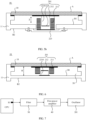
- the oscillator 201 includes a first magnet 21 and a second magnet 22.
- the first magnet 21 is disposed on the back facet of the display module 10
- the second magnet 22 is disposed on the middle frame 11, and the first magnet 21 and the second magnet 22 are disposed face to face.
- at least a part of the first magnet 21 and at least a part of the second magnet 22 are located in the accommodation space 20.
- the first magnet 21 is a coil 211
- the second magnet 22 is a main magnet 2210.
- the coil 211 is disposed on the back facet of the display module 10, and the main magnet 2210 is disposed on the middle frame 11.
- the first magnet 21 is a main magnet 2210, and the second magnet is a coil 211.
- the main magnet 2210 is disposed on the back facet of the display module 10, and the coil 211 is disposed on the middle frame 11.
- a part of the main magnet 2210 is embedded in a closed region wound by a wire of the coil 211.
- the second magnet 22 for example, the main magnet 2210 shown in FIG. 5a or the coil 211 shown in FIG. 5b
- a hole is disposed in the middle frame 11.
- the mobile terminal 01 includes a support 223. At least a part of the main magnet 2210 or the coil 211 is located in the hole on the middle frame 11.
- the support 223 may be fastened to the second surface B2 (a surface of a side away from the display module 10) of the middle frame 11 through pasting by using an adhesive layer or through a threaded connection (a screw connection is used as an example in FIG. 5a ).
- the second magnet 22 (for example, the main magnet 2210 shown in FIG. 5a or the coil 211 shown in FIG. 5b ) passes through the hole on the middle frame 11, and is disposed on the support 223.
- the second magnet 22 may be fastened, by using an adhesive layer, to a surface that is of the support 223 and that is close to the display module 10.
- the entire oscillator 201 may be disposed between the display module 10 and the middle frame 11.
- both the main magnet 2210 and the coil 211 are located in the accommodation space 20 between the display module 10 and the middle frame 11.
- the second magnet 22 (for example, the main magnet 2210 shown in FIG. 6 ) may be directly fastened, by using an adhesive layer, to a surface of a side that is of the middle frame 11 and that is close to the display module 10.
- positions of the main magnet 2210 and the coil 211 in FIG. 6 may alternatively be exchanged.
- the first magnet 21 is the main magnet 2210
- the second magnet 22 is the coil 211.
- the coil 211 used as the second magnet 22 may be directly fastened, by using the adhesive layer, to the surface of the side that is of the middle frame 11 and that is close to the display module 10.
- the mobile terminal 01 shown in FIG. 5a is used as an example to describe a process in which the mobile terminal 01 implements sound on display.
- the coil 211 is electrically connected to the first signal end S1 of the CPU.
- a first drive signal provided by the first signal end S1 of the CPU is transmitted to the coil 211 in the oscillator 201 after being processed by a filter 30 and a first power amplifier 40.
- the filter 30 can filter out a low-frequency signal from the first drive signal, so that a frequency of the first drive signal is closer to a frequency of the sound system.
- the first power amplifier 40 can amplify a signal output by the filter 30, so that the coil 211 in the oscillator 201 identifies an amplified first drive signal.
- the coil 211 when the coil 211 receives the first drive signal (that is, an intermediate-frequency or high-frequency signal), the coil 211 generates an alternating magnetic field under an action of the first drive signal.
- the first drive signal that is, an intermediate-frequency or high-frequency signal
- a magnitude and a direction of the magnetic field generated by the coil 211 vary with a change of the first drive signal. For example, when the coil 211 receives the first drive signal, if a current in the coil 211 is relatively large, strength of the magnetic field generated by the coil 211 is relatively large; or if a current in the coil 211 is relatively small, strength of the magnetic field generated by the coil 211 is relatively small.
- a transmission direction of the current in the coil 211 may control the direction of the magnetic field generated by the coil 211.
- the main magnet 2210 may be a permanent magnet, or an electromagnet receiving a constant current. In this case, the main magnet 2210 generates a constant magnetic field with a constant size and direction.
- the first drive signal is the intermediate-frequency or high-frequency signal, and the frequency of the first drive signal is close to the resonance frequency of the sound system. Therefore, under interaction of the foregoing two magnetic fields, the coil 211 in the sound system may be enabled to vibrate up and down in a magnetic line cutting manner at a small amplitude and a high frequency along the foregoing Z direction.
- the coil 211 in the oscillator 201 is connected to the display module 10. Therefore, in a process of vibrating up and down along a Z direction, the coil 211 can drive the display module 10 to vibrate up and down at a small amplitude and a high frequency in a same direction.
- the coil 211, the display module 10, and the foam adhesive 111 used to fasten the display module 10 form the sound system, and the display module 10 is used as a diaphragm to push air to generate sounds in the vibration process, so as to implement sound on display.
- the sound system can implement a function of a receiver or a speaker, to play an audio signal.
- the frequency of the first drive signal is proportional to a vibration frequency of the display module 10.
- a magnitude of the first drive signal that is, a magnitude of a current flowing into the coil 211
- a direction of the first drive signal that is, a direction of a current flowing into the coil 211
- a vibration form including a vibration frequency, an amplitude, a direction, and the like
- the oscillator 201 further includes a support plate 212.
- An upper surface of the support plate 212 is fixedly mounted on a surface of a side that is of the display module 10 and that is close to the middle frame 11, and a lower surface of the support plate 212 is fixedly connected to the first magnet 21 (for example, the coil 211 shown in FIG. 5a or the main magnet 2210 shown in FIG. 5b ).
- the first magnet 21 is connected to the display module 10 through the support plate 212.
- the support plate 212 is of a sheet structure, a contact area between the support plate 212 and the display module 10 is relatively large. Therefore, the upper surface and the lower surface of the support plate 212 are respectively in contact with the display module 10 and the first magnet 21, so that a contact area between the first magnet 21 and the display module 10 can be increased, and a driving force provided for the display module 10 can be applied to the display module 10 more evenly in a vibration process of the first magnet 21.
- a deformed area of the display module 10 may be further expanded, so that vibration efficiency of the display module 10 driven by the first magnet 21 is increased, power consumption is reduced, and a sound on display effect is improved.
- a material that forms the support plate 212 may be a metal material or another material with a relatively hard texture.
- the first magnet 21 for example, the coil 211 shown in FIG. 5a or the main magnet 2210 shown in FIG. 5b
- the display module 10 and the foam adhesive 111 form the sound system.
- the resonance frequency of the sound system may be determined by elastic coefficients of the first magnet 21, the support plate 212, the display module 10, and the foam adhesive 111.
- the coil 211 in the oscillator 201 when the coil 211 in the oscillator 201 receives the intermediate-frequency or high-frequency signal, an electric field generated by the coil 211 interacts with an electric field generated by the main magnet 2210, so that the coil 211 shown in FIG. 5a can drive the display module 10 to vibrate at a relatively small amplitude and a high frequency.
- the display module 10 is used as the diaphragm to push the air to generate sounds.
- the coil 211, the display module 10, and the foam adhesive 111 used to fasten the display module 10 to the middle frame 11 form the sound system, to implement the function of the speaker or the receiver.
- a sound hole does not need to be disposed in the mobile terminal 01, so that a problem that sound quality is affected because the sound hole is blocked can be resolved.
- a hole opening process in the mobile terminal 01 is reduced, so that a surface of a display side of the mobile terminal 01 is more flat and rounded.
- FIG. 5a is used as an example for description in the foregoing.
- a process of implementing sound on display shown in FIG. 5b and FIG. 6 is the same as that described above. Details are not described herein again.
- the coil 211 is disposed on the middle frame 11 as the second magnet 22.
- a lower surface of the coil 211 may be fastened, by using an adhesive layer, to an upper surface of the support 223 connected to the middle frame 11.
- the coil 211 needs to be electrically connected to the first signal end S1 of the CPU mounted on the middle frame 11, to separately receive the first drive signal provided by the first signal end S1. Therefore, the coil 211 is also mounted on the middle frame 11, so that an electrical connection manner between the coil 211 and the CPU can be simplified, and reliability of an electrical connection between the coil 211 and the CPU can be improved.
- the first magnet 21 is used as the main magnet 2210 and is disposed on the back facet of the display module 10. This can avoid a problem that a display effect of the display module 10 is reduced because the coil 211 is heated after the coil 211 is powered on in a solution in which the coil 211 is used as the first magnet 21 and is connected to the display module 10.
- the first magnet 21 is a coil 211
- the second magnet 22 is a main magnet 2210.
- a part of the main magnet 2210 is embedded in a closed region wound by a wire of the coil 211.
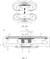
- the oscillator 201 further includes at least one auxiliary magnet 2211 located around the main magnet 2210.
- the auxiliary magnet 2211 and the main magnet 2210 are located on a same side. In this case, as shown in FIG. 8a , when the main magnet 2210 is disposed on the middle frame 11 by using the support 223, the auxiliary magnet 2211 is also disposed on the middle frame 11. Alternatively, when the main magnet 2210 is disposed on a back facet of the display module 10, the auxiliary magnet 2211 is also disposed on the back facet of the display module 10.
- the main magnet 2210 is located in the closed region wound by the wire of the coil 211.
- four auxiliary magnets 2211 are disposed around the main magnet 2210, to form five magnetic circuits.
- a circular main magnet 2210 is located in an annular auxiliary magnet 2211, to form dual magnetic circuits.
- the magnetic field generated by the coil 211 not only can interact with the magnetic field generated by the main magnet 2210, but also can interact with a magnetic field generated by the at least one auxiliary magnet 2211, to achieve an objective of improving vibration intensity of the coil 211 or vibration intensity of the main magnet 2210.
- the oscillator 201 further includes a magnetic bowl 226.
- An upper surface of the magnetic bowl 226 is fixedly connected to lower surfaces of the main magnet 2210 and the auxiliary magnet 2211 by using an adhesive layer.
- a lower surface of the magnetic bowl 226 passes through a hole in the middle frame 11, and is fastened to the upper surface of the support 223 by using the adhesive layer.
- the magnetic bowl 226 may be made of stainless steel.
- the magnetic bowl 226 may have a magnetic isolation function, to reduce a probability that magnetic fields generated by the main magnet 2210 and the auxiliary magnet 2211 have an adverse impact on another device in the mobile terminal 01.
- the oscillator 201 further includes a washer 225 (a black cover layer that is of the main magnet 2210 and the auxiliary magnet 2211 and that is close to an upper surface of the display module 10 in FIG. 9a ) covered on a surface of a side that is of the main magnet 2210 and the auxiliary magnet 2211 and that is close to the display module 10.
- the washer 225 is made of low-carbon steel.
- the washer has a magnetic conduction function, to reduce magnetic resistance of the main magnet 2210 and the auxiliary magnet 2211.
- the washer 225 has the magnetic isolation function.
- positions of the main magnet 2210, the auxiliary magnet 2211, and the coil 211 in FIG. 8a may alternatively be exchanged.
- the first magnet 21 is the main magnet 2210
- the second magnet 22 is the coil 211.
- the main magnet 2210 and the auxiliary magnet 2211 are fastened to the back facet of the display module 10
- the coil 211 is fastened to the upper surface of the support 223 by passing through the hole on the middle frame.
- the washer 225 covers a surface of a side that is of the main magnet 2210 and the auxiliary magnet 2211 and that is away from the display module 10.
- a process in which a mobile terminal having this structure implements sound on display is the same as that described above. Details are not described herein again.
- the first magnet 21 is a coil 211
- the second magnet 22 is a main magnet 2210.
- the coil 211 may be disposed on a back facet of the display module 10, and the main magnet 2210 is disposed on the middle frame 11.
- the first magnet 21 is a main magnet 2210
- the second magnet 22 is a coil 211.
- the main magnet 2210 may be disposed on the back facet of the display module 10, and the coil 211 is disposed on the middle frame 11.
- annular structure shown in FIG. 8b or FIG. 8c may be used as a top view structure of the coil 211.
- Example 1 a difference from Example 1 lies in that the main magnet 2210 is located outside a closed region wound by a wire of the coil 211.
- the main magnet 2210 is parallel to a surface opposite to the coil 211.
- the main magnet 2210 does not need to be embedded in the closed region wound by the wire of the coil 211, resolving a problem that the main magnet 2210 and the closed region wound by the wire of the coil 211 cannot be aligned. Therefore, alignment precision of the main magnet 2210 and the coil 211 is reduced, and difficulty in assembling the entire mobile terminal 01 is reduced.
- a magnetic field generated by the coil 211 and a magnetic field generated by the main magnet 2210 may generate an attraction force.
- a magnetic field generated by the coil 211 and a magnetic field generated by the main magnet 2210 may generate a repulsive force.
- vibration directions of the coil 211 and the main magnet 2210 are opposite.
- the distance may be less than or equal to 0.7 mm. In some embodiments of this application, the distance may further be less than or equal to 0.4 mm.
- the mobile terminal 01 shown in FIG. 9a and FIG. 9b can also implement the sound on display process described above.
- a difference lies in that, in this example, when the coil 211 in the oscillator 201 receives the first drive signal, the magnetic field generated by the coil 211 and the magnetic field generated by the main magnet 2210 enable the coil 211 and the main magnet 2210 to attract or repel each other, so that the first magnet 21 (for example, the coil 211 shown in FIG. 9a , or the main magnet 2210 shown in FIG. 9b ) vibrates, relative to the second magnet 22 (for example, the main magnet 2210 shown in FIG. 9a , or the coil 211 shown in FIG. 9b ), at a small amplitude and a high frequency along a Z direction. In this way, the first magnet 21 drives the display module 10 to vibrate at a small amplitude and a high frequency, to implement the sound on display.
- the mobile terminal 01 provided in some embodiments of this application further includes a first magnetic shield 51 and a second magnetic shield 52 shown in FIG. 9a or FIG. 9b .
- all surfaces except at least a surface of a side facing the main magnet 2210 are wrapped by the second magnetic shield 52.
- the first magnet 21 is a coil 211
- the second magnet 22 is a main magnet 2210.
- the main magnet 2210 is located outside a closed region wound by a wire of the coil 211.
- the main magnet 2210 is parallel to a surface opposite to the coil 211.
- a structure of the coil 211 is the same as that in Example 3.
- the oscillator 201 further includes an auxiliary magnet 2211.
- the auxiliary magnet 2211 and the coil 211 are located on a same side, and the auxiliary magnet 2211 is embedded in the closed region wound by the wire of the coil 211.
- the magnetic field generated by the coil 211 not only can interact with the magnetic field generated by the main magnet 2210, but also can interact with a magnetic field generated by the auxiliary magnet 2211, to achieve an objective of improving vibration intensity of the coil 211 or vibration intensity of the main magnet 2210.
- the auxiliary magnet 2211 is located in the second magnetic shield 52.
- a surface that is of the coil 211 and that is opposite to the auxiliary magnet 2211 is not covered by the second magnetic shield 52.
- the first magnetic shield 51 and the second magnetic shield 52 are U-shaped.
- the first magnetic shield 51 and the second magnetic shield 52 are made of a magnetic conductive material, so as to reduce diffusion of a magnetic line in the magnetic fields generated by the main magnet 2210 and the coil 211, thereby achieving an objective of reducing magnetic resistance.
- the mobile terminal 01 shown in FIG. 11 can also implement the sound on display process described above. Details are not described herein again.
- positions of the main magnet 2210, the coil 211 and the auxiliary magnet 2211 in FIG. 11 may alternatively be exchanged.
- the first magnet 21 is the main magnet 2210
- the second magnet 22 is the coil 211.
- the main magnet 2210 is fastened to the back facet of the display module 10
- the coil 211 and the auxiliary magnet 2211 are fastened to the upper surface of the support 223 by passing through the hole on the middle frame 11.
- a process in which a mobile terminal having this structure implements sound on display is the same as that described above. Details are not described herein again.
- the mobile terminal 01 further includes an elastic element 202 connected to the oscillator 201.
- the elastic element 202 is fixedly mounted on the middle frame 11, and the elastic element 202 can deform under an action of an external force.
- the coil 211 in the oscillator 201 is electrically connected to the first signal end S1 of the CPU.
- the first signal end S1 of the CPU may provide, in a time-division manner, the first drive signal and a second drive signal to the coil 211 in the oscillator 201.
- the coil 211 in the oscillator 201 is further electrically connected to a second signal end S2 (shown in FIG. 1 ) of the CPU, and the coil 211 in the oscillator 201 is configured to receive the second drive signal provided by the second signal end S2.
- the second drive signal may be a low-frequency signal, for example, a signal whose frequency is less than about 250 Hz.
- the second drive signal may be a vibration signal that is sent by a central processing unit (central processing unit, CPU) of the mobile phone to the coil 211 and that is triggered by a signal of an incoming call or a receiving message.
- CPU central processing unit
- the oscillator 201 vibrates at a large amplitude and a low frequency based on the second drive signal.
- the elastic element 202 is connected to the oscillator 201, when the oscillator 201 vibrates at a large amplitude and a low frequency in a Z direction, the elastic element 202 can deform due to force, and then vibrate with the oscillator 201 along the Z direction.
- the elastic element 202 can drive the middle frame 11 and the mobile terminal 01 that includes the display module 10 connected to the middle frame 11, the housing 12, and the like, to implement relatively large and low-frequency vibration of the entire mobile terminal.
- vibration alert of the mobile phone may be implemented when there is an incoming call or an incoming message.
- the elastic element 202 may be a spring plate 222.
- the spring plate 222 is prone to deform under an action of an external force, and vibrates up and down along a Z direction. In this case, when the oscillator 201 vibrates at a large amplitude and a low frequency, an acting force can be applied to the spring plate 222.
- the spring plate 222 deforms under the acting force, and vibrates with the oscillator 201.
- the following describes a structure of the mobile terminal 01 having the spring plate 222.
- a hole is disposed in the middle frame 11, and in a case in which the mobile terminal 01 includes the support 223, the mobile terminal 01 further includes a support block 224.
- the spring plate 222 and the support block 224 are located in the hole on the middle frame 11.
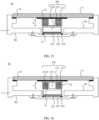
- the spring plate 222 is located between the second magnet 22 and the support 223. The following describes a disposing position of the spring plate 222.
- the spring plate 222 is directly connected to a lower surface of the main magnet 2210 by using an adhesive layer (a black cover layer on an upper surface of the spring plate 222).
- the main magnet 2210 in a case in which the main magnet 2210 is located in a closed region wound by a wire of the coil 211, when the mobile terminal 01 further includes an auxiliary magnet 2211 located on a same side as the main magnet 2210, the main magnet 2210 and the auxiliary magnet 2211 may be disposed on the magnetic bowl 226.
- the spring plate 222 is connected to a lower surface of the magnetic bowl 226 by using an adhesive layer.
- the spring plate 222 is connected to a lower surface of the first magnetic shield 51 by using an adhesive layer.
- the mobile terminal further includes the auxiliary magnet 2211 shown in FIG. 16 , because the auxiliary magnet 2211 is located on a same side as the coil 211, and is embedded in the closed region wound by the wire of the coil 211, the spring plate 222 is still connected, by using an adhesive layer, to the lower surface of the first magnetic shield 51 in which the main magnet 2210 is accommodated.
- the second magnet 22 is the coil 211 shown in FIG. 17 or FIG. 18 is used to describe a disposing position of the spring plate 222.
- the spring plate 222 is directly connected to a lower surface of the coil 211 by using an adhesive layer.
- the spring plate 222 is connected, by using an adhesive layer, to a lower surface of the second magnetic shield 52 in which the coil 211 is accommodated.
- the support block 224 is disposed between the spring plate 222 and the support 223, and an upper surface and a lower surface of the support block 224 are respectively connected to the spring plate 222 and the support 223.
- a specific gap may exist between the spring plate 222 and the support 223 when no external force is applied to the spring plate 222, and the gap may be used as a bounce space in which the spring plate 222 deforms under an external force.
- vibration of the spring plate 222 may be transferred to the middle frame 11 through the support 223.
- the spring plate 222 when a structure of the mobile terminal 01 is shown in FIG. 19 , and the spring plate 222, the support block 224, the first magnet 21 (for example, the coil 211 in FIG. 19 ), the second magnet 22 (for example, the main magnet 2210 in FIG. 19 ), and the auxiliary magnet 2211 in the mobile terminal 01 are all located in the accommodation space 20, to make the spring plate 222 have some bounce space, the spring plate 222 may be located between the second magnet 22 and the middle frame 11, and the spring plate 222 may be connected to the second magnet 22 by using an adhesive layer.
- the support block 224 is disposed between the spring plate 222 and the middle frame 11, and an upper surface and a lower surface of the support block 224 are respectively connected to the spring plate 222 and the middle frame 11.
- a specific gap may exist between the spring plate 222 and the middle frame 11 when no external force is applied to the spring plate 222, and the gap may be used as a bounce space in which the spring plate 222 deforms under an external force.
- the second magnet 22 for example, the main magnet 2210 in FIG. 19
- vibration of the spring plate 222 may be transferred to the middle frame 11.
- the spring plate 222 can drive the middle frame 11 to vibrate, and drive, by using the middle frame 11, the entire mobile terminal 01 to vibrate. Therefore, the spring plate 222 may be used as a vibration system that drives the entire mobile terminal 01 to vibrate. In this case, an elastic coefficient of the spring plate 222 can affect a resonance frequency of the vibration system.
- the resonance frequency of the spring plate 222 changes, and the resonance frequency of the vibration system also changes.
- a frequency of the second drive signal needs to be the same as or approximately the same as the resonance frequency of the vibration system.
- FIG. 13 a structure shown in FIG. 13 is used as an example to describe a process in which the mobile terminal 01 implements vibration of the entire mobile terminal.
- the second drive signal provided by the second signal end S2 of the CPU is transmitted to the coil 211 in the oscillator 201 after being processed by a second power amplifier 41.
- the second power amplifier 41 can amplify the second signal end S2, so that the coil 211 identifies an amplified second drive signal.
- the coil 211 After the coil 211 receives the second drive signal (that is, a low-frequency signal), the coil 211 generates an alternating magnetic field under an action of the second drive signal.
- the second drive signal that is, a low-frequency signal
- the main magnet 2210 generates a constant magnetic field with a constant size and direction.
- the second drive signal is a low-frequency signal, and has a relatively large difference from the resonance frequency of the sound system. Therefore, when the two magnetic fields interact with each other, the coil 211 in the sound system does not drive the display module 10 used as a diaphragm to vibrate at a high frequency, and consequently, the display module 10 cannot drive air to make sounds.
- the sound system is in a non-working state.
- the frequency of the second drive signal is close to the resonance frequency of the spring plate 222 used as the vibration system. Therefore, interaction between the magnetic field generated by the coil 211 and the magnetic field of the main magnet 2210 can drive the spring plate 222 to move up and down along a Z direction.
- the spring plate 222 drives the middle frame 11 to vibrate by using the support 223.
- the display module 10 connected to the middle frame 11, the housing 12, and the like vibrate together at a low frequency and a large amplitude.
- the vibration system is in a working state, and the entire mobile terminal 01 vibrates.
- the vibration system may play a role of a motor, and may implement vibration alert of the mobile phone when there is an incoming call or an incoming message.
- the spring plate 222 may implement a function of the motor, and the motor does not need to be separately disposed in the mobile terminal 01. Compared with the motor, the spring plate 222 has a smaller volume, thereby saving more architecture space. A component with another function, such as a front-facing camera, a rear-facing camera, and a fingerprint sensor, may be disposed in the architecture space. In this way, integration of functions of the mobile terminal 01 is improved.
- FIG. 13 is used as an example to describe a process in which the mobile terminal 01 implements sound on display and vibration of the entire mobile terminal.
- the first drive signal provided by the first signal end S1 of the CPU is transmitted to the coil 211 in the oscillator 201 after being processed by the filter 30 and the first power amplifier 40.
- the second drive signal provided by the second signal end S2 of the CPU is transmitted to the coil 211 after being processed by the second power amplifier 41.
- the coil 211 in the oscillator 201 may receive both the first drive signal (that is, an intermediate-frequency or high-frequency signal) and the second drive signal (that is, a low-frequency signal).
- a frequency of a superimposed signal received by the coil 211 is a sum of a frequency (for example, 1000 Hz) of the first drive signal and a frequency (for example, 100 Hz) of the second drive signal.
- a waveform of the superimposed signal is no longer a harmonic waveform.
- the coil 211 generates an alternating magnetic field under an action of the superimposed signal. Under an action of the alternating magnetic field and the constant magnetic field generated by the main magnet 2210, the coil 211 is driven to drive the display module 10 to vibrate at a small amplitude and a high frequency in the Z direction.
- the display module 10 is used as a diaphragm to push air to generate sounds in the vibration process, to implement sound on display. In this case, the sound system is in a working state.
- the coil 211 drives the main magnet 2210 to drive the spring plate 222 to move up and down along the Z direction.
- the spring plate 222 drives the middle frame 11 to vibrate by using the support 223.
- the display module 10 connected to the middle frame 11, the housing 12, and the like vibrate together at a low frequency and a large amplitude. In this case, the vibration system is in a working state, and the entire mobile terminal 01 vibrates.
- the resonance frequency of the sound system including the first magnet 21 (for example, the coil 211 shown in FIG. 13 or the main magnet 2210 shown in FIG. 17 ), the display module 10, and the foam adhesive 111 is far greater than the resonance frequency of the vibration system including the spring plate 222. Therefore, the spring plate 222 can work as a frequency divider.
- the coil 211 receives an intermediate-frequency or high-frequency first drive signal
- the first magnet 21 drives the display module 10 to vibrate, so that the sound system works, thereby implementing the sound on display.
- the second magnet 22 drives the spring plate 222 and the middle frame 11 connected to the spring plate 222 to vibrate, so that the vibration system works, thereby implementing the vibration of the entire mobile terminal.
- FIG. 13 describes, by using the mobile terminal 01 shown in FIG. 13 as an example, a process in which the mobile terminal 01 implements the sound on display and the vibration of the entire mobile terminal.
- FIG. 14 , FIG. 15 , FIG. 16 , FIG. 17 , FIG. 18 , and FIG. 19 may also implement the sound on display and the vibration of the entire mobile terminal. Details are not described herein again.
- a disposing manner of the oscillator 201 and the spring plate 222 in the mobile terminal 01 provided in the embodiments of this application may use a structure described in any one of the foregoing examples.
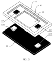
- the mobile terminal 01 may include at least two oscillators 201.
- a groove 60 for embedding a battery is disposed in a middle position of the middle frame 11.
- the two oscillators 201 are respectively located at an upper end and a lower end of the groove 60, and are disposed away from a clearance area of an antenna.
- a hole (not shown in the figure) for embedding the oscillator 201 may be disposed in the middle frame 11, or the hole may not be disposed, and the two oscillators 201 are directly disposed on the middle frame 11.
- the hole for embedding the oscillator 201 may be disposed on the middle frame 11 is used.
- the first magnet 21 in the oscillator 201 may be disposed on a back facet of the display module 10, and is directly opposite to a position of the hole disposed on the middle frame 11.
- a part of the second magnet 22 in the oscillator 201 is located in the hole, and is fastened to the support 223.
- the support 223 is fastened to the second surface B2 of the middle frame 11 by using screws.
- the first magnet 21 in the oscillator 201 may be disposed on the display module 10, and is directly opposite to a position of the hole disposed on the middle frame 11.
- the second magnet 22 in the oscillator 201 for example, a part of the coil 211 shown in FIG. 5b , and the spring plate 222 are located in the hole, and are fastened to the support 223.
- the support 223 is fastened to the second surface B2 of the middle frame 11 by using screws.
- the main magnet 2210 is disposed on the display module 10, and the coil 211 is disposed on the middle frame 11. This can avoid a problem that a display effect of the display module 10 is reduced because the coil 211 is heated.
- an electrical connection manner between the coil 211 and the CPU can be further simplified, and reliability of an electrical connection between the coil 211 and the CPU can be improved.
- the first magnet 21 in the oscillator 201 for example, the coil 211 shown in FIG. 5a
- the second magnet 22 in the oscillator 201 for example, a part of the main magnet 2210 shown in FIG. 5a
- the spring plate 222 are located in the hole, and are fastened to the support 223.
- the support 223 is fastened to the second surface B2 of the middle frame 11 by using screws.
- the mobile terminal 01 includes two oscillators 201.
- the oscillator 201 may be disposed on an upper side of the mobile terminal 01.
- the oscillator 201 can be located near an ear of the user.
- the mobile terminal 01 implements the sound on display by using the oscillator 201, in a process in which the user answers the mobile phone, an effect of the sound on display at a location of an ear is better, and a voice signal is clearer.
Landscapes
- Engineering & Computer Science (AREA)
- Signal Processing (AREA)
- Physics & Mathematics (AREA)
- Acoustics & Sound (AREA)
- Multimedia (AREA)
- Computer Networks & Wireless Communication (AREA)
- Electromagnetism (AREA)
- Telephone Set Structure (AREA)
- Apparatuses For Generation Of Mechanical Vibrations (AREA)
Description
- This application relates to the field of display technologies, and in particular, to a mobile terminal.
- Functions of a mobile terminal, for example, a mobile phone, tend to be increasingly diversified. A plurality of devices, for example, a camera, a receiver, and a photosensitive device used for fingerprint collection, used to implement different functions need to be integrated into the mobile phone. However, because an architecture space inside the mobile phone is limited, there is no enough space to deploy more functional devices, and consequently, an integration effect of functions of the mobile phone is reduced.
- In document
US 2018/317012 A1 A display apparatus capable of realizing uniform sound wave and improved sound quality is described. The display apparatus may include a display panel for displaying an image, a supporting member for supporting a rear surface of the display panel, at least one sound generating device disposed between the supporting member and the display panel, at least one partition provided at a predetermined interval from at least one sound generating device, and an adhesion member disposed in the periphery of the display panel. - In document
US 2002/065113 A1 An electron device, in which accommodation space for a display can be extended over the space where a speaker is supposed to be disposed, is described. A portable terminal, as an example of an electron device, is provided with a display/speaker section, an operating section, and a microphone on the front surface of its main body. The portable terminal does not have an independent speaker. A display cover located in front of the display/speaker section for protecting the display surface vibrates in response to an audio signal by a drive to output sound. Consequently, the display can be situated even over the space where a speaker is supposed to be disposed. - In document
US 2014/241564 A1 A sound output mechanism of a mobile device is described that is capable of outputting visual and sound signals, for example, a smart phone, tablet PC, MP4 (including MP3) and has an image output unit and a sound processing unit. The image output unit of the mobile device is arranged on the entire surface of a main body and the sound processing unit for outputting vibration power and sound is firmly secured at the inside thereof without increasing the volume or the area thereof. - Embodiments of this application provide a mobile terminal, to resolve a problem that an architecture space inside the mobile terminal is relatively small.
- Another object of the present invention is to provide a mobile terminal that enables an improved sound generation using a display of the mobile terminal with increased efficiency and reduced power consumption.
- To achieve the foregoing objective, the following technical solutions are used in this application:
A mobile terminal according to the present invention comprises a housing, and a middle frame and a display module that are disposed in the housing, wherein the display module is connected to the middle frame, and an accommodation space is formed between the display module and the middle frame. The mobile terminal further comprises a first magnet and a second magnet, wherein at least a part of the first magnet and at least a part of the second magnet are disposed in the accommodation space, and the first magnet is disposed on a back facet of the display module, the second magnet is disposed on the middle frame, and the first magnet and the second magnet are disposed face to face. The mobile terminal further comprises a support plate that is configured to improve a vibration effect of the display module, wherein an upper surface of the support plate is connected to the display module, and a lower surface of the support plate is connected to the first magnet, and an area of the upper surface of the support plate is greater than an area of a surface of a side that is of the first magnet and that is close to the support plate. - According to an aspect of the embodiments of this application, a mobile terminal is provided, including a housing, and a middle frame and a display module that are disposed in the housing. The display module may be mounted on a bearing table of the middle frame by using foam adhesive, so that the display module is connected to the middle frame. An accommodation space is formed between the display module and the middle frame. In addition, the mobile terminal further includes a first magnet and a second magnet, and at least a part of the first magnet and at least a part of the second magnet are disposed in the accommodation space. The first magnet is disposed on a back facet of the display module, the second magnet is disposed on the middle frame, and the first magnet and the second magnet are disposed face to face. In this case, the foam adhesive used to fasten the display module to the middle frame is elastic to some extent, and can be deformed under an action of an external force. In this way, when the first magnet receives the first drive signal used as a high-frequency signal, and when the first magnet may vibrate, under an effect of a magnetic field generated by the first magnet and a magnetic field generated by the second magnet, in a direction perpendicular to a light-emitting surface of the display module, the first magnet may drive the display module to move up and down, relative to the middle frame, at a small amplitude and a high frequency. In this case, the small-amplitude and high-frequency vibration of the display module cannot drive the middle frame to vibrate. Therefore, the middle frame is approximately in a static state. In this case, driven by the first magnet, the display module is used as a diaphragm to push air to generate sounds in the vibration process, so as to implement sound on display, thereby implementing a function of a receiver or a speaker. In this case, a sound hole does not need to be disposed in the mobile terminal, so that a problem that sound quality is affected because the sound hole is blocked can be resolved. In addition, a hole opening process in the mobile terminal is reduced, so that a surface of a display side of the mobile terminal is more flat and rounded.
- Optionally, the first magnet is a coil, and the second magnet is a main magnet. Alternatively, the first magnet is a main magnet, and the second magnet is a coil. When the first magnet is a coil, the coil, the display module, and the foam adhesive used to fasten the display module to the middle frame form a sound system used to implement the sound on display. In a process of implementing the sound on display, the coil drives the display module to be used as the diaphragm, to push the air to generate sounds in the vibration process. Alternatively, when the first magnet is a main magnet, the main magnet, the display module, and the foam adhesive used to fasten the display module to the middle frame form a sound system used to implement the sound on display. In a process of implementing the sound on display, the main magnet drives the display module to be used as the diaphragm, to push the air to generate sounds in the vibration process.
- Optionally, a part of the main magnet is embedded in a closed region wound by a wire of the coil. In this case, in the process of implementing the sound on display, after the coil receives the first drive signal, when the first magnet is the coil, a magnetic field generated by the coil interacts with a magnetic field generated by the main magnet, so that the coil drives the display module to vibrate up and down in a magnetic line cutting manner at a small amplitude and a high frequency. Alternatively, when the first magnet is the main magnet, the main magnet is reacted by the coil, and the coil drives the display module to vibrate at a high frequency.
- Optionally, the mobile terminal further includes at least one auxiliary magnet. The auxiliary magnet and the main magnet are located on a same side, and there is a gap between the auxiliary magnet and the main magnet. In addition, a part of the coil is located in the gap between the auxiliary magnet and the main magnet. In this way, the magnetic field generated by the coil not only can interact with the magnetic field generated by the main magnet, but also can interact with a magnetic field generated by the at least one auxiliary magnet, to achieve an objective of improving vibration intensity of the coil or vibration intensity of the main magnet.
- Optionally, the main magnet is located outside a closed region wound by a wire of the coil. In addition, the main magnet is parallel to a surface opposite to the coil. In this case, in the process of implementing the sound on display, when the coil receives the first drive signal, the coil and the main magnet can attract or repel each other in the magnetic field generated by the coil and the magnetic field generated by the main magnet, so that the first magnet (the coil or the main magnet) vibrates, relative to the second magnet (the main magnet or the coil), at a small amplitude and a high frequency. In this way, the first magnet drives the display module to vibrate at a small amplitude and a high frequency, to implement the sound on display.
- Optionally, the mobile terminal further includes one auxiliary magnet. The auxiliary magnet and the coil are located on a same side, and the auxiliary magnet is embedded in the closed region wound by the wire of the coil. A technical effect of the auxiliary magnet is the same as that described above. Details are not described herein again.
- Optionally, a hole is disposed in the middle frame. The mobile terminal includes a support. At least a part of the second magnet is located in the hole on the middle frame. The support is disposed on a surface of a side that is of the middle frame and that is away from the display module, and is connected to the middle frame. In addition, the second magnet passes through the hole on the middle frame, and is disposed on the support. The hole is formed on the middle frame, so that the second magnet can pass through the hole and be disposed on the surface of the side that is of the middle frame and that is away from the display module. In this way, a spacing between the first magnet and the second magnet can be increased, thereby helping increase a vibration space of the first magnet and the second magnet.
- Optionally, the mobile terminal further includes a spring plate and a support block. The spring plate and the support block are located in the hole on the middle frame. The spring plate is located between the second magnet and the support, and the spring plate is connected to the second magnet. In addition, the support block is disposed between the spring plate and the support, and an upper surface and a lower surface of the support block are respectively connected to the spring plate and the support. A resonance frequency of a sound system including the first magnet, the display module, and the foam adhesive is far greater than a resonance frequency of a vibration system including the spring plate. Therefore, the spring plate can work as a frequency divider. When the coil receives an intermediate-frequency or high-frequency first drive signal, the first magnet drives the display module to vibrate, so that the sound system works, thereby implementing the sound on display. When the coil receives a low-frequency second drive signal, the second magnet drives the spring plate and the middle frame connected to the spring plate to vibrate, so that the vibration system works, thereby implementing vibration of an entire mobile terminal.
- Optionally, the mobile terminal further includes a spring plate and a support block. The spring plate, the support block, the first magnet, and the second magnet are all located in the accommodation space. In addition, the spring plate is located between the second magnet and the middle frame, and the spring plate is connected to the second magnet. The support block is disposed between the spring plate and the middle frame, and an upper surface and a lower surface of the support block are respectively connected to the spring plate and the middle frame. When a gap between the display module and the middle frame is large enough, components such as the first magnet, the second magnet, and the spring plate may all be disposed in the accommodation space formed between the display module and the middle frame. A technical effect of the spring plate is the same as that described above. Details are not described herein again.
- The mobile terminal further includes a support plate. An upper surface of the support plate is connected to the display module, and a lower surface of the support plate is connected to the first magnet. An area of the upper surface of the support plate is greater than an area of a surface of a side that is of the first magnet and that is close to the support plate. In this way, because the support plate is of a sheet structure, a contact area between the support plate and the display module is relatively large. Therefore, the upper surface and the lower surface of the support plate are respectively in contact with the display module and the first magnet, so that a contact area between the first magnet and the display module can be increased, and a driving force provided for the display module can be applied to the display module more evenly in a vibration process of the first magnet. In addition, by using the support plate, a deformed area of the display module may be further expanded, so that vibration efficiency of the display module driven by the first magnet is increased, power consumption is reduced, and a sound on display effect is improved.
- Optionally, the mobile terminal further includes a washer. When the first magnet is the main magnet, the washer is located on a surface of a side that is of the main magnet and that is away from the display module. Alternatively, when the second magnet is the main magnet, the washer is located on a surface of a side that is of the main magnet and that is away from the middle frame. The washer is made of low-carbon steel. The washer has a magnetic conduction function, to reduce magnetic resistance of the main magnet. In addition, the washer has a magnetic isolation function.
- Optionally, the mobile terminal further includes a magnetic bowl for carrying the main magnet. When the second magnet is the main magnet, the magnetic bowl is located on a surface of a side that is of the main magnet and that is away from the display module. The magnetic bowl may be made of stainless steel. In this case, the magnetic bowl may have a magnetic isolation function, to reduce a probability that a magnetic field generated by the main magnet has an adverse impact on another device in the mobile terminal.
- Optionally, the mobile terminal further includes a first magnetic shield and a second magnetic shield. The main magnet is located in the first magnetic shield, and for the main magnet, all surfaces except a surface of a side facing the coil are wrapped by the first magnetic shield. In addition, the coil is located in the second magnetic shield, and for the coil, all surfaces except at least a surface of a side facing the main magnet are wrapped by the second magnetic shield. The first magnetic shield may reduce a probability that a magnetic field generated by the main magnet has an adverse impact on another device in the mobile terminal, and the second magnetic shield may reduce a probability that a magnetic field generated by the coil has an adverse impact on another device in the mobile terminal.
- Optionally, when the mobile terminal includes the auxiliary magnet, the auxiliary magnet is located in the second magnetic shield, and a surface that is of the coil and that is opposite to the auxiliary magnet is not covered by the second magnetic shield. The second magnetic shield may further reduce a probability that a magnetic field generated by the auxiliary magnet has an adverse impact on another device in the mobile terminal.
-
-
FIG. 1 is a schematic structural diagram of a mobile terminal according to an embodiment of this application; -
FIG. 2 is a schematic structural diagram of a display module shown inFIG. 1 ; -
FIG. 3 is another schematic structural diagram of a display module shown inFIG. 1 ; -
FIG. 4a is a schematic structural diagram of a mobile terminal with an oscillator according to an embodiment of this application; -
FIG. 4b is a schematic structural diagram of an oscillator in the mobile terminal shown inFIG. 4a ; -
FIG. 5a is a schematic structural diagram of a first magnet and a second magnet in the mobile terminal shown inFIG. 4b ; -
FIG. 5b is another schematic structural diagram of a first magnet and a second magnet in the mobile terminal shown inFIG. 4b ; -
FIG. 6 is another schematic structural diagram of a mobile terminal with an oscillator according to an embodiment of this application; -
FIG. 7 is a schematic diagram of signal transmission in which the mobile terminal shown inFIG. 4b implements sound on display; -
FIG. 8a is another schematic structural diagram of a first magnet and a second magnet in the mobile terminal shown inFIG. 4b ; -
FIG. 8b is a top view of a coil and a main magnet shown inFIG. 8a ; -
FIG. 8c is another top view of a coil and a main magnet shown inFIG. 8a ; -
FIG. 9a is another schematic structural diagram of a first magnet and a second magnet in the mobile terminal shown inFIG. 4b ; -
FIG. 9b is another schematic structural diagram of a first magnet and a second magnet in the mobile terminal shown inFIG. 4a ; -
FIG. 10a is a schematic diagram of interaction between a magnetic field generated by a coil and a magnetic field generated by a main magnet shown inFIG. 9a ; -
FIG. 10b is another schematic diagram of interaction between a magnetic field generated by a coil and a magnetic field generated by a main magnet shown inFIG. 9a ; -
FIG. 11 is another schematic structural diagram of a first magnet and a second magnet in the mobile terminal shown inFIG. 4a ; -
FIG. 12a is a schematic structural diagram of a mobile terminal with an oscillator and an elastic element according to an embodiment of this application; -
FIG. 12b is a schematic structural diagram of the elastic element inFIG. 12a ; -
FIG. 13 is a schematic diagram of a disposing manner of an oscillator and a spring plate in a mobile terminal shown inFIG. 12b ; -
FIG. 14 is another schematic diagram of a disposing manner of an oscillator and a spring plate in a mobile terminal shown inFIG. 12b ; -
FIG. 15 is another schematic diagram of a disposing manner of an oscillator and a spring plate in a mobile terminal shown inFIG. 12b ; -
FIG. 16 is another schematic diagram of a disposing manner of an oscillator and a spring plate in a mobile terminal shown inFIG. 12b ; -
FIG. 17 is another schematic diagram of a disposing manner of an oscillator and a spring plate in a mobile terminal shown inFIG. 12b ; -
FIG. 18 is another schematic diagram of a disposing manner of an oscillator and a spring plate in a mobile terminal shown inFIG. 12b ; -
FIG. 19 is a schematic diagram of a disposing manner of an oscillator and a spring plate in the mobile terminal shown inFIG. 12a ; -
FIG. 20a is a schematic diagram of signal transmission in which the mobile terminal shown inFIG. 13 implements vibration of an entire mobile terminal; -
FIG. 20b is a schematic diagram of signal transmission in which the mobile terminal shown inFIG. 13 implements sound on display and vibration of an entire mobile terminal; and -
FIG. 21 is a schematic diagram of a disposing manner in which a mobile terminal includes a plurality of oscillators according to an embodiment of this application. - 01-mobile terminal; 10-display module; 101-display panel; 102-back light unit; 103-cover; 11-middle frame; 110-bearing table; 111-foam adhesive; 12-housing; 20-accommodation space; 21-first magnet; 22-second magnet; 201-oscillator; 211-coil; 212-support plate; 202-elastic element; 2210-main magnet; 2211-auxiliary magnet; 222-spring plate; 223-support; 224-support block; 225-washer; 226-magnetic bowl; 30-filter; 40-first power amplifier; 41-second power amplifier; 51-first magnetic shield; 52-second magnetic shield; 60-groove.
- The following describes the technical solutions in the embodiments of this application with reference to the accompanying drawings in the embodiments of this application. It is clearly that the described embodiments are merely a part rather than all of the embodiments of this application.
- The following terms "first" and "second" are merely intended for a purpose of description, and shall not be understood as an indication or implication of relative importance or implicit indication of a quantity of indicated technical features. Therefore, a feature limited by "first" or "second" may explicitly or implicitly include one or more such features.
- In addition, in this application, orientation terms such as "upper" and "lower" are defined relative to an orientation in which a component is schematically placed in the accompanying drawings. It should be understood that these orientation terms are relative concepts and are used for relative description and clarification, and these orientation terms may change accordingly based on changes of the orientation in which the component is placed in the accompanying drawings.
- An embodiment of this application provides a
mobile terminal 01 shown inFIG. 1 . Themobile terminal 01 includes, for example, a mobile phone, a tablet computer, a personal digital assistant (personal digital assistant, PDA), and a vehicle-mounted computer. A specific form of themobile terminal 01 is not particularly limited in this embodiment of this application. For ease of description, an example in which themobile terminal 01 is a mobile phone is used for description. - As shown in
FIG. 1 , themobile terminal 01 mainly includes adisplay module 10, amiddle frame 11, and ahousing 12. Thedisplay module 10 and themiddle frame 11 are disposed in thehousing 12. Themobile terminal 01 further includes a central processing unit (Central Processing Unit, CPU) disposed on a PCB. - As shown in
FIG. 2 , thedisplay module 10 includes a display panel (display panel, DP) 101. - In some embodiments of this application, the
display panel 101 may be a liquid crystal display (liquid crystal display, LCD). In this case, thedisplay module 10 further includes a back light unit (back light unit, BLU) 102 configured to provide a light source for the liquid crystal display. - Alternatively, in some other embodiments of this application, as shown in
FIG. 3 , thedisplay panel 101 is an organic light-emitting diode (organic light emitting diode, OLED) display, and the OLED display can implement self-luminescence. Therefore, no BLU needs to be disposed in thedisplay module 10. - It should be noted that, a substrate in the OLED display may be made of a flexible resin material. In this case, the OLED display is a flexible display.
- Alternatively, the substrate in the OLED display may be made of a relatively hard material, for example, glass. In this case, the OLED display is a hard display.
- In some embodiments of this application, as shown in
FIG. 2 or FIG. 3 , thedisplay module 10 further includes acover 103 located on a display side of thedisplay panel 101, for example, a cover glass (cover glass, CG). The cover glass has specific toughness. - In addition, as shown in
FIG. 1 , themiddle frame 11 is located between thedisplay module 10 and thehousing 12. - As shown in
FIG. 4a , a bearing table 110 in a ring shape is disposed on a side that is of themiddle frame 11 and that is close to thedisplay module 10.Foam adhesive 111 is pasted on the bearing table 110. Thedisplay module 10 is fastened to themiddle frame 11 by using thefoam adhesive 111, so that thedisplay module 10 is connected to themiddle frame 11. - A gap H exists between a back facet of the
display module 10 fastened to the bearing table 110 and a first surface B1 of themiddle frame 11, and the gap H forms anaccommodation space 20. - It should be noted that the
display module 10 has a light-emitting surface that can display an image. The back facet of thedisplay module 10 refers to a surface of a side that is of thedisplay module 10 and that is opposite to the light-emitting surface, that is, a surface of a side that is of thedisplay module 10 and that is close to themiddle frame 11. - In addition, internal components such as a battery, a printed circuit board (printed circuit board, PCB), a camera (camera), and an antenna are mounted on a second surface B2 of the
middle frame 11. - It should be noted that the first surface B1 and the second surface B2 of the
middle frame 11 are disposed opposite to each other. The first surface B1 is close to thedisplay module 10, and the second surface B2 is close to thehousing 12. - The
housing 12 is mounted on themiddle frame 11, and thehousing 12 can protect the foregoing internal components mounted on the second surface B2 of themiddle frame 11. - In addition, the
mobile terminal 01 further includes at least oneoscillator 201 shown inFIG. 4a . Theoscillator 201 is connected to thedisplay module 10 and themiddle frame 11. - In this case, the
oscillator 201 is further electrically connected to a first signal end S1 (shown inFIG. 1 ) of the CPU. Theoscillator 201 is configured to: receive a first drive signal provided by the first signal end S1; and drive, based on the first drive signal, thedisplay module 10 to vibrate in a direction perpendicular to the light-emitting surface A of thedisplay module 10. - In some embodiments of this application, the first drive signal may be an intermediate-frequency or high-frequency signal, for example, a signal whose frequency is higher than 250 Hz. For example, when the
mobile terminal 01 is a mobile phone, the first drive signal may be an audio analog signal that is sent by the CPU of the mobile phone to theoscillator 201 and that is corresponding to an audio digital signal. - It can be learned from the foregoing description that the
display module 10 is mounted on the bearing table 110 by using thefoam adhesive 111. Thefoam adhesive 111 is elastic to some extent, and can be deformed under an action of an external force. In this way, when theoscillator 201 vibrates, based on the first drive signal, in the direction perpendicular to the light-emitting surface A of thedisplay module 10, theoscillator 201 drives thedisplay module 10 to move up and down, relative to themiddle frame 11, at a small amplitude and a high frequency. - In this case, the small-amplitude and high-frequency vibration of the
display module 10 cannot drive themiddle frame 11 to vibrate. Therefore, themiddle frame 11 is approximately in a static state. - In this case, driven by the
oscillator 201, thedisplay module 10 is used as a diaphragm to push air to generate sounds in the vibration process, so as to implement sound on display. - It can be learned from the foregoing description that the
display panel 101 in thedisplay module 10 may be the LCD or the OLED display. In addition, compared with the LCD, the OLED display can self-illuminate. Therefore, a BLU does not need to be disposed in thedisplay module 10, and thedisplay module 10 is thin. When thedisplay module 10 is used as the diaphragm to implement the sound on display, deformation is more likely to occur, so that a sound effect of the diaphragm is better. - In this case, a partial structure of the
oscillator 201, thedisplay module 10, and the foam adhesive 111 used to fasten thedisplay module 10 to themiddle frame 11 form a sound system used to implement the sound on display. In this case, the partial structure in theoscillator 201, thedisplay module 10, and an elastic coefficient of thefoam adhesive 111 may affect a resonance frequency of the sound system. - Based on this, to make the sound system have a good vibration effect, a frequency of the first drive signal is the same as or approximately the same as the resonance frequency of the sound system.
- In some embodiments of this application, as shown in
FIG. 4b , theoscillator 201 includes afirst magnet 21 and asecond magnet 22. Thefirst magnet 21 is disposed on the back facet of thedisplay module 10, thesecond magnet 22 is disposed on themiddle frame 11, and thefirst magnet 21 and thesecond magnet 22 are disposed face to face. In addition, at least a part of thefirst magnet 21 and at least a part of thesecond magnet 22 are located in theaccommodation space 20. - The following describes in detail, by using examples, structures and disposing manners of the
first magnet 21 and thesecond magnet 22 in theoscillator 201. - In this example, as shown in
FIG. 5a , thefirst magnet 21 is acoil 211, and thesecond magnet 22 is amain magnet 2210. - In this case, the
coil 211 is disposed on the back facet of thedisplay module 10, and themain magnet 2210 is disposed on themiddle frame 11. - Alternatively, as shown in
FIG. 5b , thefirst magnet 21 is amain magnet 2210, and the second magnet is acoil 211. - In this case, the
main magnet 2210 is disposed on the back facet of thedisplay module 10, and thecoil 211 is disposed on themiddle frame 11. - In addition, in this example, a part of the
main magnet 2210 is embedded in a closed region wound by a wire of thecoil 211. - To enable the second magnet 22 (for example, the
main magnet 2210 shown inFIG. 5a or thecoil 211 shown inFIG. 5b ) to be disposed on themiddle frame 11, in some embodiments of the present disclosure, as shown inFIG. 5a orFIG. 5b , a hole is disposed in themiddle frame 11. - The
mobile terminal 01 includes asupport 223. At least a part of themain magnet 2210 or thecoil 211 is located in the hole on themiddle frame 11. - The
support 223 may be fastened to the second surface B2 (a surface of a side away from the display module 10) of themiddle frame 11 through pasting by using an adhesive layer or through a threaded connection (a screw connection is used as an example inFIG. 5a ). - In this case, the second magnet 22 (for example, the
main magnet 2210 shown inFIG. 5a or thecoil 211 shown inFIG. 5b ) passes through the hole on themiddle frame 11, and is disposed on thesupport 223. Thesecond magnet 22 may be fastened, by using an adhesive layer, to a surface that is of thesupport 223 and that is close to thedisplay module 10. - Alternatively, in some other embodiments of the present disclosure, as shown in
FIG. 6 , when the spacing H between thedisplay module 10 and themiddle frame 11 is large enough, theentire oscillator 201 may be disposed between thedisplay module 10 and themiddle frame 11. - In this case, both the
main magnet 2210 and thecoil 211 are located in theaccommodation space 20 between thedisplay module 10 and themiddle frame 11. - In this case, the second magnet 22 (for example, the
main magnet 2210 shown inFIG. 6 ) may be directly fastened, by using an adhesive layer, to a surface of a side that is of themiddle frame 11 and that is close to thedisplay module 10. - In addition, in some embodiments of this application, positions of the
main magnet 2210 and thecoil 211 inFIG. 6 may alternatively be exchanged. To be specific, thefirst magnet 21 is themain magnet 2210, and thesecond magnet 22 is thecoil 211. Similarly, thecoil 211 used as thesecond magnet 22 may be directly fastened, by using the adhesive layer, to the surface of the side that is of themiddle frame 11 and that is close to thedisplay module 10. - Based on this, the
mobile terminal 01 shown inFIG. 5a is used as an example to describe a process in which themobile terminal 01 implements sound on display. - The
coil 211 is electrically connected to the first signal end S1 of the CPU. In this case, to implement a sound on display mode, as shown inFIG. 7 , a first drive signal provided by the first signal end S1 of the CPU is transmitted to thecoil 211 in theoscillator 201 after being processed by afilter 30 and afirst power amplifier 40. - The
filter 30 can filter out a low-frequency signal from the first drive signal, so that a frequency of the first drive signal is closer to a frequency of the sound system. - In addition, the
first power amplifier 40 can amplify a signal output by thefilter 30, so that thecoil 211 in theoscillator 201 identifies an amplified first drive signal. - In this case, when the
coil 211 receives the first drive signal (that is, an intermediate-frequency or high-frequency signal), thecoil 211 generates an alternating magnetic field under an action of the first drive signal. - A magnitude and a direction of the magnetic field generated by the
coil 211 vary with a change of the first drive signal. For example, when thecoil 211 receives the first drive signal, if a current in thecoil 211 is relatively large, strength of the magnetic field generated by thecoil 211 is relatively large; or if a current in thecoil 211 is relatively small, strength of the magnetic field generated by thecoil 211 is relatively small. - In addition, a transmission direction of the current in the
coil 211 may control the direction of the magnetic field generated by thecoil 211. - The
main magnet 2210 may be a permanent magnet, or an electromagnet receiving a constant current. In this case, themain magnet 2210 generates a constant magnetic field with a constant size and direction. - It can be learned from the foregoing description that the first drive signal is the intermediate-frequency or high-frequency signal, and the frequency of the first drive signal is close to the resonance frequency of the sound system. Therefore, under interaction of the foregoing two magnetic fields, the
coil 211 in the sound system may be enabled to vibrate up and down in a magnetic line cutting manner at a small amplitude and a high frequency along the foregoing Z direction. - In the sound system, the
coil 211 in theoscillator 201 is connected to thedisplay module 10. Therefore, in a process of vibrating up and down along a Z direction, thecoil 211 can drive thedisplay module 10 to vibrate up and down at a small amplitude and a high frequency in a same direction. - In this way, the
coil 211, thedisplay module 10, and the foam adhesive 111 used to fasten thedisplay module 10 form the sound system, and thedisplay module 10 is used as a diaphragm to push air to generate sounds in the vibration process, so as to implement sound on display. In this case, the sound system can implement a function of a receiver or a speaker, to play an audio signal. - It should be noted that the frequency of the first drive signal is proportional to a vibration frequency of the
display module 10. In addition, a magnitude of the first drive signal, that is, a magnitude of a current flowing into thecoil 211, is proportional to a vibration intensity of thedisplay module 10. A direction of the first drive signal, that is, a direction of a current flowing into thecoil 211, is proportional to a vibration direction of thedisplay module 10. Therefore, when the first drive signal is changed, a vibration form (including a vibration frequency, an amplitude, a direction, and the like) of thedisplay module 10 driven by thecoil 211 correspondingly changes, so that sounds generated by the sound system are different. - Based on this, to improve a vibration effect of the
display module 10, as shown inFIG. 5a orFIG. 5b , theoscillator 201 further includes asupport plate 212. An upper surface of thesupport plate 212 is fixedly mounted on a surface of a side that is of thedisplay module 10 and that is close to themiddle frame 11, and a lower surface of thesupport plate 212 is fixedly connected to the first magnet 21 (for example, thecoil 211 shown inFIG. 5a or themain magnet 2210 shown inFIG. 5b ). In this case, thefirst magnet 21 is connected to thedisplay module 10 through thesupport plate 212. - In this way, because the
support plate 212 is of a sheet structure, a contact area between thesupport plate 212 and thedisplay module 10 is relatively large. Therefore, the upper surface and the lower surface of thesupport plate 212 are respectively in contact with thedisplay module 10 and thefirst magnet 21, so that a contact area between thefirst magnet 21 and thedisplay module 10 can be increased, and a driving force provided for thedisplay module 10 can be applied to thedisplay module 10 more evenly in a vibration process of thefirst magnet 21. - In addition, by using the
support plate 212, a deformed area of thedisplay module 10 may be further expanded, so that vibration efficiency of thedisplay module 10 driven by thefirst magnet 21 is increased, power consumption is reduced, and a sound on display effect is improved. - It should be noted that a material that forms the
support plate 212 may be a metal material or another material with a relatively hard texture. - It can be learned from the foregoing description that the first magnet 21 (for example, the
coil 211 shown inFIG. 5a or themain magnet 2210 shown inFIG. 5b ), thedisplay module 10, and thefoam adhesive 111 form the sound system. The resonance frequency of the sound system may be determined by elastic coefficients of thefirst magnet 21, thesupport plate 212, thedisplay module 10, and thefoam adhesive 111. - In addition, there is a relatively large difference between the frequency of the first drive signal and a resonance frequency of the
middle frame 11. Therefore, interaction between the magnetic field generated by thecoil 211 and the magnetic field of themain magnet 2210 cannot drive themiddle frame 11 to move up and down along a Z direction, and themiddle frame 11 is in a static state. - In conclusion, in the
mobile terminal 01 in this application, when thecoil 211 in theoscillator 201 receives the intermediate-frequency or high-frequency signal, an electric field generated by thecoil 211 interacts with an electric field generated by themain magnet 2210, so that thecoil 211 shown inFIG. 5a can drive thedisplay module 10 to vibrate at a relatively small amplitude and a high frequency. Thedisplay module 10 is used as the diaphragm to push the air to generate sounds. In this way, thecoil 211, thedisplay module 10, and the foam adhesive 111 used to fasten thedisplay module 10 to themiddle frame 11 form the sound system, to implement the function of the speaker or the receiver. - In this case, a sound hole does not need to be disposed in the
mobile terminal 01, so that a problem that sound quality is affected because the sound hole is blocked can be resolved. In addition, a hole opening process in themobile terminal 01 is reduced, so that a surface of a display side of themobile terminal 01 is more flat and rounded. - It should be noted that the structure shown in
FIG. 5a is used as an example for description in the foregoing. A process of implementing sound on display shown inFIG. 5b and FIG. 6 is the same as that described above. Details are not described herein again. - In addition, in
FIG. 5b , thecoil 211 is disposed on themiddle frame 11 as thesecond magnet 22. For example, a lower surface of thecoil 211 may be fastened, by using an adhesive layer, to an upper surface of thesupport 223 connected to themiddle frame 11. In this way, it can be learned from the foregoing description that thecoil 211 needs to be electrically connected to the first signal end S1 of the CPU mounted on themiddle frame 11, to separately receive the first drive signal provided by the first signal end S1. Therefore, thecoil 211 is also mounted on themiddle frame 11, so that an electrical connection manner between thecoil 211 and the CPU can be simplified, and reliability of an electrical connection between thecoil 211 and the CPU can be improved. - In addition, the
first magnet 21 is used as themain magnet 2210 and is disposed on the back facet of thedisplay module 10. This can avoid a problem that a display effect of thedisplay module 10 is reduced because thecoil 211 is heated after thecoil 211 is powered on in a solution in which thecoil 211 is used as thefirst magnet 21 and is connected to thedisplay module 10. - In this example, as shown in
FIG. 8a , thefirst magnet 21 is acoil 211, and thesecond magnet 22 is amain magnet 2210. - A part of the
main magnet 2210 is embedded in a closed region wound by a wire of thecoil 211. - In addition, a difference from Example 1 lies in that, as shown in
FIG. 8a , theoscillator 201 further includes at least oneauxiliary magnet 2211 located around themain magnet 2210. - The
auxiliary magnet 2211 and themain magnet 2210 are located on a same side. In this case, as shown inFIG. 8a , when themain magnet 2210 is disposed on themiddle frame 11 by using thesupport 223, theauxiliary magnet 2211 is also disposed on themiddle frame 11. Alternatively, when themain magnet 2210 is disposed on a back facet of thedisplay module 10, theauxiliary magnet 2211 is also disposed on the back facet of thedisplay module 10. - In addition, there is a gap between the
auxiliary magnet 2211 and themain magnet 2210. A part of thecoil 211 is located in the gap between theauxiliary magnet 2211 and themain magnet 2210. - In this case, as shown in
FIG. 8b orFIG. 8c , themain magnet 2210 is located in the closed region wound by the wire of thecoil 211. As shown inFIG. 8b , fourauxiliary magnets 2211 are disposed around themain magnet 2210, to form five magnetic circuits. Alternatively, inFIG. 8c , a circularmain magnet 2210 is located in an annularauxiliary magnet 2211, to form dual magnetic circuits. - In this way, the magnetic field generated by the
coil 211 not only can interact with the magnetic field generated by themain magnet 2210, but also can interact with a magnetic field generated by the at least oneauxiliary magnet 2211, to achieve an objective of improving vibration intensity of thecoil 211 or vibration intensity of themain magnet 2210. - In addition, to support the
main magnet 2210, or themain magnet 2210 and theauxiliary magnet 2211, as shown inFIG. 8a , theoscillator 201 further includes amagnetic bowl 226. An upper surface of themagnetic bowl 226 is fixedly connected to lower surfaces of themain magnet 2210 and theauxiliary magnet 2211 by using an adhesive layer. A lower surface of themagnetic bowl 226 passes through a hole in themiddle frame 11, and is fastened to the upper surface of thesupport 223 by using the adhesive layer. - The
magnetic bowl 226 may be made of stainless steel. In this case, themagnetic bowl 226 may have a magnetic isolation function, to reduce a probability that magnetic fields generated by themain magnet 2210 and theauxiliary magnet 2211 have an adverse impact on another device in themobile terminal 01. - In addition, to improve uniformity of the magnetic fields generated by the
main magnet 2210 and theauxiliary magnet 2211, theoscillator 201 further includes a washer 225 (a black cover layer that is of themain magnet 2210 and theauxiliary magnet 2211 and that is close to an upper surface of thedisplay module 10 inFIG. 9a ) covered on a surface of a side that is of themain magnet 2210 and theauxiliary magnet 2211 and that is close to thedisplay module 10. Thewasher 225 is made of low-carbon steel. The washer has a magnetic conduction function, to reduce magnetic resistance of themain magnet 2210 and theauxiliary magnet 2211. In addition, thewasher 225 has the magnetic isolation function. It should be noted that themobile terminal 01 shown inFIG. 8a can also implement the sound on display process described in Example 1. Details are not described herein again. - In addition, in some embodiments of this application, positions of the
main magnet 2210, theauxiliary magnet 2211, and thecoil 211 inFIG. 8a may alternatively be exchanged. To be specific, thefirst magnet 21 is themain magnet 2210, and thesecond magnet 22 is thecoil 211. In this case, themain magnet 2210 and theauxiliary magnet 2211 are fastened to the back facet of thedisplay module 10, and thecoil 211 is fastened to the upper surface of thesupport 223 by passing through the hole on the middle frame. In this case, thewasher 225 covers a surface of a side that is of themain magnet 2210 and theauxiliary magnet 2211 and that is away from thedisplay module 10. A process in which a mobile terminal having this structure implements sound on display is the same as that described above. Details are not described herein again. - In this example, as shown in
FIG. 9a , thefirst magnet 21 is acoil 211, and thesecond magnet 22 is amain magnet 2210. - In this case, the
coil 211 may be disposed on a back facet of thedisplay module 10, and themain magnet 2210 is disposed on themiddle frame 11. - Alternatively, as shown in
FIG. 9b , thefirst magnet 21 is amain magnet 2210, and thesecond magnet 22 is acoil 211. - In this case, the
main magnet 2210 may be disposed on the back facet of thedisplay module 10, and thecoil 211 is disposed on themiddle frame 11. - In this example, an annular structure shown in
FIG. 8b orFIG. 8c may be used as a top view structure of thecoil 211. - In addition, a difference from Example 1 lies in that the
main magnet 2210 is located outside a closed region wound by a wire of thecoil 211. Themain magnet 2210 is parallel to a surface opposite to thecoil 211. - In this way, in a process of assembling the
oscillator 201, themain magnet 2210 does not need to be embedded in the closed region wound by the wire of thecoil 211, resolving a problem that themain magnet 2210 and the closed region wound by the wire of thecoil 211 cannot be aligned. Therefore, alignment precision of themain magnet 2210 and thecoil 211 is reduced, and difficulty in assembling the entiremobile terminal 01 is reduced. - In this case, after the
coil 211 is powered on, as shown inFIG. 10a , a magnetic field generated by thecoil 211 and a magnetic field generated by themain magnet 2210 may generate an attraction force. - Alternatively, after a direction of a current flowing into the
coil 211 changes, as shown inFIG. 10b , a magnetic field generated by thecoil 211 and a magnetic field generated by themain magnet 2210 may generate a repulsive force. - In this case, under an effect of the magnetic field generated by the
coil 211 and the magnetic field generated by themain magnet 2210, vibration directions of thecoil 211 and themain magnet 2210 are opposite. - It should be noted that when the electrified
coil 211 and themain magnet 2210 vibrate close to each other, opposite surfaces of the two are not in contact with each other. When the electrifiedcoil 211 and themain magnet 2210 vibrate away from each other, there is a specific distance between the opposite surfaces of the two. To avoid increasing the thickness of themobile terminal 01, the distance may be less than or equal to 0.7 mm. In some embodiments of this application, the distance may further be less than or equal to 0.4 mm. - The
mobile terminal 01 shown inFIG. 9a andFIG. 9b can also implement the sound on display process described above. A difference lies in that, in this example, when thecoil 211 in theoscillator 201 receives the first drive signal, the magnetic field generated by thecoil 211 and the magnetic field generated by themain magnet 2210 enable thecoil 211 and themain magnet 2210 to attract or repel each other, so that the first magnet 21 (for example, thecoil 211 shown inFIG. 9a , or themain magnet 2210 shown inFIG. 9b ) vibrates, relative to the second magnet 22 (for example, themain magnet 2210 shown inFIG. 9a , or thecoil 211 shown inFIG. 9b ), at a small amplitude and a high frequency along a Z direction. In this way, thefirst magnet 21 drives thedisplay module 10 to vibrate at a small amplitude and a high frequency, to implement the sound on display. - In addition, to reduce a probability that the magnetic fields generated by the
coil 211 and themain magnet 2210 have an adverse impact on another device in the mobile terminal, themobile terminal 01 provided in some embodiments of this application further includes a firstmagnetic shield 51 and a secondmagnetic shield 52 shown inFIG. 9a orFIG. 9b . - For the
main magnet 2210, all surfaces except a surface of a side facing thecoil 211 are wrapped by the firstmagnetic shield 51. - For the
coil 211, all surfaces except at least a surface of a side facing themain magnet 2210 are wrapped by the secondmagnetic shield 52. - In this example, as shown in
FIG. 11 , thefirst magnet 21 is acoil 211, and thesecond magnet 22 is amain magnet 2210. - The
main magnet 2210 is located outside a closed region wound by a wire of thecoil 211. Themain magnet 2210 is parallel to a surface opposite to thecoil 211. A structure of thecoil 211 is the same as that in Example 3. - A difference from Example 3 lies in that, as shown in
FIG. 11 , theoscillator 201 further includes anauxiliary magnet 2211. Theauxiliary magnet 2211 and thecoil 211 are located on a same side, and theauxiliary magnet 2211 is embedded in the closed region wound by the wire of thecoil 211. - In this way, the magnetic field generated by the
coil 211 not only can interact with the magnetic field generated by themain magnet 2210, but also can interact with a magnetic field generated by theauxiliary magnet 2211, to achieve an objective of improving vibration intensity of thecoil 211 or vibration intensity of themain magnet 2210. - In addition, when the
mobile terminal 01 includes theauxiliary magnet 2211, because theauxiliary magnet 2211 and thecoil 211 are located on a same side, theauxiliary magnet 2211 is located in the secondmagnetic shield 52. A surface that is of thecoil 211 and that is opposite to theauxiliary magnet 2211 is not covered by the secondmagnetic shield 52. In this case, the firstmagnetic shield 51 and the secondmagnetic shield 52 are U-shaped. - On this basis, the first
magnetic shield 51 and the secondmagnetic shield 52 are made of a magnetic conductive material, so as to reduce diffusion of a magnetic line in the magnetic fields generated by themain magnet 2210 and thecoil 211, thereby achieving an objective of reducing magnetic resistance. - It should be noted that the
mobile terminal 01 shown inFIG. 11 can also implement the sound on display process described above. Details are not described herein again. - In addition, in some embodiments of this application, positions of the
main magnet 2210, thecoil 211 and theauxiliary magnet 2211 inFIG. 11 may alternatively be exchanged. To be specific, thefirst magnet 21 is themain magnet 2210, and thesecond magnet 22 is thecoil 211. In this case, themain magnet 2210 is fastened to the back facet of thedisplay module 10, and thecoil 211 and theauxiliary magnet 2211 are fastened to the upper surface of thesupport 223 by passing through the hole on themiddle frame 11. A process in which a mobile terminal having this structure implements sound on display is the same as that described above. Details are not described herein again. - The foregoing describes a structure of the
mobile terminal 01 by using an example in which themobile terminal 01 implements the sound on display. In some embodiments of this application, as shown inFIG. 12a , themobile terminal 01 further includes anelastic element 202 connected to theoscillator 201. Theelastic element 202 is fixedly mounted on themiddle frame 11, and theelastic element 202 can deform under an action of an external force. - In this case, the
coil 211 in theoscillator 201 is electrically connected to the first signal end S1 of the CPU. The first signal end S1 of the CPU may provide, in a time-division manner, the first drive signal and a second drive signal to thecoil 211 in theoscillator 201. - Alternatively, in some other embodiments of this application, the
coil 211 in theoscillator 201 is further electrically connected to a second signal end S2 (shown inFIG. 1 ) of the CPU, and thecoil 211 in theoscillator 201 is configured to receive the second drive signal provided by the second signal end S2. - It should be noted that the second drive signal may be a low-frequency signal, for example, a signal whose frequency is less than about 250 Hz. For example, when the
mobile terminal 01 is a mobile phone, the second drive signal may be a vibration signal that is sent by a central processing unit (central processing unit, CPU) of the mobile phone to thecoil 211 and that is triggered by a signal of an incoming call or a receiving message. - In this case, when the
coil 211 receives the second drive signal, theoscillator 201 vibrates at a large amplitude and a low frequency based on the second drive signal. - Because the
elastic element 202 is connected to theoscillator 201, when theoscillator 201 vibrates at a large amplitude and a low frequency in a Z direction, theelastic element 202 can deform due to force, and then vibrate with theoscillator 201 along the Z direction. - Because the
elastic element 202 is fixedly mounted on themiddle frame 11, in a vibration process, theelastic element 202 can drive themiddle frame 11 and themobile terminal 01 that includes thedisplay module 10 connected to themiddle frame 11, thehousing 12, and the like, to implement relatively large and low-frequency vibration of the entire mobile terminal. In this case, vibration alert of the mobile phone may be implemented when there is an incoming call or an incoming message. In some embodiments of this application, as shown inFIG. 12b , theelastic element 202 may be aspring plate 222. Thespring plate 222 is prone to deform under an action of an external force, and vibrates up and down along a Z direction. In this case, when theoscillator 201 vibrates at a large amplitude and a low frequency, an acting force can be applied to thespring plate 222. Thespring plate 222 deforms under the acting force, and vibrates with theoscillator 201. - To implement vibration of the entire mobile terminal, the following describes a structure of the
mobile terminal 01 having thespring plate 222. - In this example, in order to make the
spring plate 222 have some bounce space, as shown inFIG. 12b , a hole is disposed in themiddle frame 11, and in a case in which themobile terminal 01 includes thesupport 223, themobile terminal 01 further includes asupport block 224. Thespring plate 222 and thesupport block 224 are located in the hole on themiddle frame 11. - In this case, in an example in which the
second magnet 22 is themain magnet 2210 shown inFIG. 13, FIG. 14 ,FIG. 15, or FIG. 16 , thespring plate 222 is located between thesecond magnet 22 and thesupport 223. The following describes a disposing position of thespring plate 222. - For example, in some embodiments of this application, as shown in
FIG. 13 , thespring plate 222 is directly connected to a lower surface of themain magnet 2210 by using an adhesive layer (a black cover layer on an upper surface of the spring plate 222). - For another example, in some other embodiments of this application, as shown in
FIG. 14 , in a case in which themain magnet 2210 is located in a closed region wound by a wire of thecoil 211, when themobile terminal 01 further includes anauxiliary magnet 2211 located on a same side as themain magnet 2210, themain magnet 2210 and theauxiliary magnet 2211 may be disposed on themagnetic bowl 226. In this case, thespring plate 222 is connected to a lower surface of themagnetic bowl 226 by using an adhesive layer. - For another example, in some other embodiments of this application, as shown in
FIG. 15 , in a case in which themain magnet 2210 and thecoil 211 are disposed face to face, and themain magnet 2210 is located outside the closed region wound by the wire of thecoil 211, when themain magnet 2210 is located in the firstmagnetic shield 51, thespring plate 222 is connected to a lower surface of the firstmagnetic shield 51 by using an adhesive layer. - In addition, based on the structure shown in
FIG. 15 , when the mobile terminal further includes theauxiliary magnet 2211 shown inFIG. 16 , because theauxiliary magnet 2211 is located on a same side as thecoil 211, and is embedded in the closed region wound by the wire of thecoil 211, thespring plate 222 is still connected, by using an adhesive layer, to the lower surface of the firstmagnetic shield 51 in which themain magnet 2210 is accommodated. - Alternatively, an example in which the
second magnet 22 is thecoil 211 shown inFIG. 17 or FIG. 18 is used to describe a disposing position of thespring plate 222. - For example, in some other embodiments of this application, as shown in
FIG. 17 , thespring plate 222 is directly connected to a lower surface of thecoil 211 by using an adhesive layer. - For another example, in some other embodiments of this application, as shown in
FIG. 18 , when themain magnet 2210 and thecoil 211 are disposed face to face, and themain magnet 2210 is located outside the closed region wound by the wire of thecoil 211, thespring plate 222 is connected, by using an adhesive layer, to a lower surface of the secondmagnetic shield 52 in which thecoil 211 is accommodated. - In addition, the
support block 224 is disposed between thespring plate 222 and thesupport 223, and an upper surface and a lower surface of thesupport block 224 are respectively connected to thespring plate 222 and thesupport 223. - In this case, with the support of the
support block 224, a specific gap may exist between thespring plate 222 and thesupport 223 when no external force is applied to thespring plate 222, and the gap may be used as a bounce space in which thespring plate 222 deforms under an external force. In addition, when the main magnet 2210 (or the coil 211) drives thespring plate 222 to vibrate in the bounce space, vibration of thespring plate 222 may be transferred to themiddle frame 11 through thesupport 223. - In addition, in this example, when a structure of the
mobile terminal 01 is shown inFIG. 19 , and thespring plate 222, thesupport block 224, the first magnet 21 (for example, thecoil 211 inFIG. 19 ), the second magnet 22 (for example, themain magnet 2210 inFIG. 19 ), and theauxiliary magnet 2211 in themobile terminal 01 are all located in theaccommodation space 20, to make thespring plate 222 have some bounce space, thespring plate 222 may be located between thesecond magnet 22 and themiddle frame 11, and thespring plate 222 may be connected to thesecond magnet 22 by using an adhesive layer. - In addition, the
support block 224 is disposed between thespring plate 222 and themiddle frame 11, and an upper surface and a lower surface of thesupport block 224 are respectively connected to thespring plate 222 and themiddle frame 11. - In this case, with the support of the
support block 224, a specific gap may exist between thespring plate 222 and themiddle frame 11 when no external force is applied to thespring plate 222, and the gap may be used as a bounce space in which thespring plate 222 deforms under an external force. In addition, when the second magnet 22 (for example, themain magnet 2210 inFIG. 19 ) drives thespring plate 222 to vibrate in the bounce space, vibration of thespring plate 222 may be transferred to themiddle frame 11. - It can be learned from the foregoing description that the
spring plate 222 can drive themiddle frame 11 to vibrate, and drive, by using themiddle frame 11, the entiremobile terminal 01 to vibrate. Therefore, thespring plate 222 may be used as a vibration system that drives the entiremobile terminal 01 to vibrate. In this case, an elastic coefficient of thespring plate 222 can affect a resonance frequency of the vibration system. - The elastic coefficient k, a mass m, and a resonance frequency f of the
spring plate 222 satisfy the following formula (1):
- In this case, when a material and a size of the selected
spring plate 222 are different, the resonance frequency of thespring plate 222 changes, and the resonance frequency of the vibration system also changes. - Based on this, to make the vibration system have a good vibration effect, a frequency of the second drive signal needs to be the same as or approximately the same as the resonance frequency of the vibration system.
- In this case, a structure shown in
FIG. 13 is used as an example to describe a process in which themobile terminal 01 implements vibration of the entire mobile terminal. As shown inFIG. 20a , the second drive signal provided by the second signal end S2 of the CPU is transmitted to thecoil 211 in theoscillator 201 after being processed by asecond power amplifier 41. Thesecond power amplifier 41 can amplify the second signal end S2, so that thecoil 211 identifies an amplified second drive signal. - In this case, after the
coil 211 receives the second drive signal (that is, a low-frequency signal), thecoil 211 generates an alternating magnetic field under an action of the second drive signal. - As described above, the
main magnet 2210 generates a constant magnetic field with a constant size and direction. - The second drive signal is a low-frequency signal, and has a relatively large difference from the resonance frequency of the sound system. Therefore, when the two magnetic fields interact with each other, the
coil 211 in the sound system does not drive thedisplay module 10 used as a diaphragm to vibrate at a high frequency, and consequently, thedisplay module 10 cannot drive air to make sounds. The sound system is in a non-working state. - In addition, the frequency of the second drive signal is close to the resonance frequency of the
spring plate 222 used as the vibration system. Therefore, interaction between the magnetic field generated by thecoil 211 and the magnetic field of themain magnet 2210 can drive thespring plate 222 to move up and down along a Z direction. - In this case, the
spring plate 222 drives themiddle frame 11 to vibrate by using thesupport 223. In addition, thedisplay module 10 connected to themiddle frame 11, thehousing 12, and the like vibrate together at a low frequency and a large amplitude. In this case, the vibration system is in a working state, and the entiremobile terminal 01 vibrates. The vibration system may play a role of a motor, and may implement vibration alert of the mobile phone when there is an incoming call or an incoming message. - In this case, the
spring plate 222 may implement a function of the motor, and the motor does not need to be separately disposed in themobile terminal 01. Compared with the motor, thespring plate 222 has a smaller volume, thereby saving more architecture space. A component with another function, such as a front-facing camera, a rear-facing camera, and a fingerprint sensor, may be disposed in the architecture space. In this way, integration of functions of themobile terminal 01 is improved. - In addition, the structure shown in
FIG. 13 is used as an example to describe a process in which themobile terminal 01 implements sound on display and vibration of the entire mobile terminal. - To implement a sound on display mode and a vibration of the entire
mobile terminal 01 mode, as shown inFIG. 20b , the first drive signal provided by the first signal end S1 of the CPU is transmitted to thecoil 211 in theoscillator 201 after being processed by thefilter 30 and thefirst power amplifier 40. In addition, the second drive signal provided by the second signal end S2 of the CPU is transmitted to thecoil 211 after being processed by thesecond power amplifier 41. - In this case, the
coil 211 in theoscillator 201 may receive both the first drive signal (that is, an intermediate-frequency or high-frequency signal) and the second drive signal (that is, a low-frequency signal). - It should be noted that, when both the first drive signal and the second drive signal are input to the
coil 211, a frequency of a superimposed signal received by thecoil 211 is a sum of a frequency (for example, 1000 Hz) of the first drive signal and a frequency (for example, 100 Hz) of the second drive signal. In this case, a waveform of the superimposed signal is no longer a harmonic waveform. - In this case, the
coil 211 generates an alternating magnetic field under an action of the superimposed signal. Under an action of the alternating magnetic field and the constant magnetic field generated by themain magnet 2210, thecoil 211 is driven to drive thedisplay module 10 to vibrate at a small amplitude and a high frequency in the Z direction. Thedisplay module 10 is used as a diaphragm to push air to generate sounds in the vibration process, to implement sound on display. In this case, the sound system is in a working state. - In addition, under the action of the alternating magnetic field generated by the superimposed signal and the constant magnetic field generated by the
main magnet 2210, thecoil 211 drives themain magnet 2210 to drive thespring plate 222 to move up and down along the Z direction. In this case, thespring plate 222 drives themiddle frame 11 to vibrate by using thesupport 223. In addition, thedisplay module 10 connected to themiddle frame 11, thehousing 12, and the like vibrate together at a low frequency and a large amplitude. In this case, the vibration system is in a working state, and the entiremobile terminal 01 vibrates. - In conclusion, the resonance frequency of the sound system including the first magnet 21 (for example, the
coil 211 shown inFIG. 13 or themain magnet 2210 shown inFIG. 17 ), thedisplay module 10, and thefoam adhesive 111 is far greater than the resonance frequency of the vibration system including thespring plate 222. Therefore, thespring plate 222 can work as a frequency divider. When thecoil 211 receives an intermediate-frequency or high-frequency first drive signal, thefirst magnet 21 drives thedisplay module 10 to vibrate, so that the sound system works, thereby implementing the sound on display. When thecoil 211 receives a low-frequency second drive signal, thesecond magnet 22 drives thespring plate 222 and themiddle frame 11 connected to thespring plate 222 to vibrate, so that the vibration system works, thereby implementing the vibration of the entire mobile terminal. - It should be noted that the foregoing describes, by using the
mobile terminal 01 shown inFIG. 13 as an example, a process in which themobile terminal 01 implements the sound on display and the vibration of the entire mobile terminal.FIG. 14 ,FIG. 15 ,FIG. 16 ,FIG. 17 ,FIG. 18 , andFIG. 19 may also implement the sound on display and the vibration of the entire mobile terminal. Details are not described herein again. - A disposing manner of the
oscillator 201 and thespring plate 222 in themobile terminal 01 provided in the embodiments of this application may use a structure described in any one of the foregoing examples. - Based on this, to improve uniformity of vibration of the
display module 10 when themobile terminal 01 makes sounds by implementing the sound on display, and/or uniformity of vibration of the entire mobile terminal when the entiremobile terminal 01 vibrates, themobile terminal 01 may include at least twooscillators 201. - As shown in
FIG. 21 , agroove 60 for embedding a battery is disposed in a middle position of themiddle frame 11. In this case, the twooscillators 201 are respectively located at an upper end and a lower end of thegroove 60, and are disposed away from a clearance area of an antenna. A hole (not shown in the figure) for embedding theoscillator 201 may be disposed in themiddle frame 11, or the hole may not be disposed, and the twooscillators 201 are directly disposed on themiddle frame 11. - An example in which the hole for embedding the
oscillator 201 may be disposed on themiddle frame 11 is used. When themobile terminal 01 can implement sound on display, thefirst magnet 21 in theoscillator 201 may be disposed on a back facet of thedisplay module 10, and is directly opposite to a position of the hole disposed on themiddle frame 11. In addition, a part of thesecond magnet 22 in theoscillator 201 is located in the hole, and is fastened to thesupport 223. Thesupport 223 is fastened to the second surface B2 of themiddle frame 11 by using screws. - Alternatively, when the
mobile terminal 01 can implement sound on display and entire mobile terminal vibration, as shown inFIG. 21 , thefirst magnet 21 in theoscillator 201, for example, themain magnet 2210 shown inFIG. 5b , may be disposed on thedisplay module 10, and is directly opposite to a position of the hole disposed on themiddle frame 11. In addition, thesecond magnet 22 in theoscillator 201, for example, a part of thecoil 211 shown inFIG. 5b , and thespring plate 222 are located in the hole, and are fastened to thesupport 223. Thesupport 223 is fastened to the second surface B2 of themiddle frame 11 by using screws. - It can be learned from the foregoing description that the
main magnet 2210 is disposed on thedisplay module 10, and thecoil 211 is disposed on themiddle frame 11. This can avoid a problem that a display effect of thedisplay module 10 is reduced because thecoil 211 is heated. In addition, an electrical connection manner between thecoil 211 and the CPU can be further simplified, and reliability of an electrical connection between thecoil 211 and the CPU can be improved. - Alternatively, the
first magnet 21 in theoscillator 201, for example, thecoil 211 shown inFIG. 5a , is disposed on thedisplay module 10, and is directly opposite to a position of the hole disposed on themiddle frame 11. In addition, thesecond magnet 22 in theoscillator 201, for example, a part of themain magnet 2210 shown inFIG. 5a , and thespring plate 222 are located in the hole, and are fastened to thesupport 223. Thesupport 223 is fastened to the second surface B2 of themiddle frame 11 by using screws. - The foregoing is described by using an example in which the
mobile terminal 01 includes twooscillators 201. In a case in which themobile terminal 01 has oneoscillator 201, theoscillator 201 may be disposed on an upper side of themobile terminal 01. In other words, when a user answers a call, theoscillator 201 can be located near an ear of the user. In this way, when themobile terminal 01 implements the sound on display by using theoscillator 201, in a process in which the user answers the mobile phone, an effect of the sound on display at a location of an ear is better, and a voice signal is clearer. - The foregoing descriptions are merely specific implementations of the present invention, but are not intended to limit the protection scope of the present invention. Any variation or replacement readily figured out by a person skilled in the art within the technical scope disclosed in the present invention shall fall within the protection scope of the present invention. Therefore, the protection scope of the present invention shall be subject to the protection scope of the claims.
Claims (13)
- A mobile terminal (01), comprising a housing (12), and a middle frame (11) and a display module (10) that are disposed in the housing (12), whereinthe display module (10) is connected to the middle frame (11), and an accommodation space (20) is formed between the display module (10) and the middle frame (11);the mobile terminal (01) further comprises a first magnet (21) and a second magnet (22), wherein at least a part of the first magnet (21) and at least a part of the second magnet (22) are disposed in the accommodation space (20); andthe first magnet (21) is disposed on a back facet of the display module (10), the second magnet (22) is disposed on the middle frame (11), and the first magnet (21) and the second magnet (22) are disposed face to characterised in thatthe mobile terminal (01) further comprises a support plate (212) that is configured to improve a vibration effect of the display module (10), whereinan upper surface of the support plate (212) is connected to the display module (10), and a lower surface of the support plate (212) is connected to the first magnet (21); andan area of the upper surface of the support plate (212) is greater than an area of a surface of a side that is of the first magnet (21) and that is close to the support plate (212).
- The mobile terminal (01) according to claim 1, wherein the first magnet (21) is a coil (211), and the second magnet (22) is a main magnet (2210); or,
the first magnet (21) is a main magnet (2210), and the second magnet is a coil (211). - The mobile terminal (01) according to claim 2, wherein a part of the main magnet (2210) is embedded in a closed region wound by a wire of the coil (211).
- The mobile terminal (01) according to claim 3, wherein the mobile terminal (01) further comprises at least one auxiliary magnet (2211), whereinthe auxiliary magnet (2211) and the main magnet (2210) are located on a same side, and there is a gap between the auxiliary magnet (2211) and the main magnet (2210); anda part of the coil (211) is located in the gap between the auxiliary magnet (2211) and the main magnet (2210).
- The mobile terminal (01) according to claim 2, wherein the main magnet (2210) is located outside a closed region wound by a wire of the coil (211), and the main magnet (2210) is parallel to a surface opposite to the coil (211).
- The mobile terminal (01) according to claim 5, wherein the mobile terminal (01) further comprises one auxiliary magnet (2211, wherein
the auxiliary magnet (2211) and the coil (211) are located on a same side, and the auxiliary magnet (2211) is embedded in the closed region wound by the wire of the coil (211). - The mobile terminal (01) according to any one of claims 1 to 6, wherein a hole is disposed in the middle frame (11);the mobile terminal (01) comprises a support (223), and at least a part of the second magnet (22) is located in the hole in the middle frame (11);the support (223) is disposed on a surface of a side that is of the middle frame (11) and that is away from the display module (10), and is connected to the middle frame (11); andthe second magnet (22) passes through the hole in the middle frame (11), and is disposed on the support (223).
- The mobile terminal (01) according to claim 7, wherein the mobile terminal (01) further comprises a spring plate (222) and a support block (224), wherein the spring plate (222) and the support block (224) are located in the hole in the middle frame (11);the spring plate (222) is located between the second magnet (22) and the support (223), and the spring plate (222) is connected to the second magnet (22); andthe support block (224) is disposed between the spring plate (222) and the support (223), and an upper surface and a lower surface of the support block (223) are respectively connected to the spring plate (222) and the support (223).
- The mobile terminal (01) according to any one of claims 1 to 6, wherein the mobile terminal (01) further comprises a spring plate (222) and a support block (224), whereinthe spring plate (222), the support block (224), the first magnet (21), and the second magnet (22) are all located in the accommodation space (20);the spring plate (222) is located between the second magnet (22) and the middle frame (11), and the spring plate (222) is connected to the second magnet (22); andthe support block (224) is disposed between the spring plate (222) and the middle frame (11), and an upper surface and a lower surface of the support block (224) are respectively connected to the spring plate (222) and the middle frame (11).
- The mobile terminal (01) according to claim 3 or 4, wherein the mobile terminal (01) further comprises a washer (225), whereinwhen the first magnet (21) is the main magnet (2210), the washer (225) is located on a surface of a side that is of the main magnet (2210) and that is away from the display module (10); orwhen the second magnet (22) is the main magnet (2210), the washer (225) is located on a surface of a side that is of the main magnet (2210) and that is away from the middle frame (11).
- The mobile terminal (01) according to claim 3 or 4, wherein the mobile terminal (01) further comprises a magnetic bowl (226) for carrying the main magnet (2210), wherein
when the second magnet (22) is the main magnet (2210), the magnetic bowl (226) is located on a surface of a side that is of the main magnet (2210) and that is away from the display module (10). - The mobile terminal (01) according to claim 5 or 6, wherein the mobile terminal (01) further comprises a first magnetic shield (51) and a second magnetic shield (52), whereinthe main magnet (2210) is located in the first magnetic shield (51), and for the main magnet (2210), all surfaces except a surface of a side facing the coil (211) are wrapped by the first magnetic shield (51); andthe coil (211) is located in the second magnetic shield (52), and for the coil (211), all surfaces except a surface of a side facing the main magnet (2210) are wrapped by the second magnetic shield (52).
- The mobile terminal (01) according to claim 12, wherein when the mobile terminal (01) comprises the auxiliary magnet (2211), the auxiliary magnet (2211) is located in the second magnetic shield (52), and a surface that is of the coil (211) and that faces the auxiliary magnet (2211) is not covered by the second magnetic shield (52).
Applications Claiming Priority (1)
| Application Number | Priority Date | Filing Date | Title |
|---|---|---|---|
| PCT/CN2018/116040 WO2020097940A1 (en) | 2018-11-16 | 2018-11-16 | Mobile terminal |
Publications (3)
| Publication Number | Publication Date |
|---|---|
| EP3859981A1 EP3859981A1 (en) | 2021-08-04 |
| EP3859981A4 EP3859981A4 (en) | 2021-11-10 |
| EP3859981B1 true EP3859981B1 (en) | 2024-09-25 |
Family
ID=70731311
Family Applications (1)
| Application Number | Title | Priority Date | Filing Date |
|---|---|---|---|
| EP18940415.5A Active EP3859981B1 (en) | 2018-11-16 | 2018-11-16 | Mobile terminal |
Country Status (6)
| Country | Link |
|---|---|
| US (1) | US11929775B2 (en) |
| EP (1) | EP3859981B1 (en) |
| JP (1) | JP7208389B2 (en) |
| KR (1) | KR102521804B1 (en) |
| CN (1) | CN112771836B (en) |
| WO (1) | WO2020097940A1 (en) |
Families Citing this family (9)
| Publication number | Priority date | Publication date | Assignee | Title |
|---|---|---|---|---|
| KR102711145B1 (en) * | 2019-06-07 | 2024-09-27 | 삼성디스플레이 주식회사 | Display device |
| KR102653775B1 (en) * | 2019-07-04 | 2024-04-01 | 엘지디스플레이 주식회사 | Display apparatus |
| CN112492065B (en) * | 2019-09-12 | 2022-11-11 | 华为技术有限公司 | Display terminal |
| CN112908152A (en) * | 2019-12-04 | 2021-06-04 | 深圳富泰宏精密工业有限公司 | Display module and electronic device with same |
| KR20220167037A (en) | 2021-06-11 | 2022-12-20 | 에스케이온 주식회사 | Composition for cathode of lithium secondary battery and lithium secondary battery manufactured using the same |
| CN115884050B (en) * | 2021-08-12 | 2026-05-01 | 京东方科技集团股份有限公司 | Spliced screen unit and display module |
| CN117083645B (en) * | 2022-02-23 | 2026-02-10 | 京东方科技集团股份有限公司 | fingerprint recognition module |
| CN217718365U (en) * | 2022-03-21 | 2022-11-01 | 海信视像科技股份有限公司 | Display device |
| GB202204878D0 (en) | 2022-04-04 | 2022-05-18 | Pss Belgium Nv | Loudspeaker |
Family Cites Families (48)
| Publication number | Priority date | Publication date | Assignee | Title |
|---|---|---|---|---|
| JPS5936479B2 (en) * | 1978-08-21 | 1984-09-04 | スタ−精密株式会社 | Electromagnetic acoustic transducer |
| WO1999039843A1 (en) * | 1998-02-06 | 1999-08-12 | Namiki Seimitsu Houseki Kabushiki Kaisha | Electromagnetic actuator and structure for mounting the same |
| JP3632594B2 (en) * | 2000-11-28 | 2005-03-23 | 日本電気株式会社 | Electronic equipment |
| JP4197992B2 (en) | 2003-06-17 | 2008-12-17 | 三洋電機株式会社 | Flat speaker and electronic device using the same |
| EP1480489A3 (en) | 2003-05-23 | 2009-07-01 | Alps Electric Co., Ltd. | Exciting device for producing sound |
| JP4215624B2 (en) | 2003-11-20 | 2009-01-28 | シチズン電子株式会社 | Sound equipment |
| KR100685451B1 (en) * | 2004-06-24 | 2007-02-23 | 신기음향 주식회사 | Receiver unit of portable mobile communication terminal |
| KR100698256B1 (en) | 2004-07-16 | 2007-03-22 | 엘지전자 주식회사 | Speaker device using display window |
| JP4086823B2 (en) | 2004-09-03 | 2008-05-14 | Necアクセステクニカ株式会社 | Panel type speaker, speaker-integrated display and electronic device |
| WO2006137665A1 (en) | 2005-06-21 | 2006-12-28 | U-Gentech Co., Ltd | Micro speaker unit |
| JP2007300578A (en) | 2006-05-08 | 2007-11-15 | Goto Denshi Kk | Display device and electronic device |
| JP5528040B2 (en) | 2008-10-03 | 2014-06-25 | Dowaエレクトロニクス株式会社 | COMPOSITE OXIDE FOR EXHAUST GAS PURIFYING CATALYST, ITS MANUFACTURING METHOD, COATING FOR EXHAUST GAS PURIFYING CATALYST, DIESEL EXHAUST PURIFYING FILTER |
| CN201629840U (en) | 2010-02-25 | 2010-11-10 | 厦门冠音泰科技有限公司 | Structure of oscillation sounder |
| KR101012299B1 (en) * | 2010-03-30 | 2011-02-08 | 주식회사 엠소닉 | Speaker device and electronic device having same |
| KR101250288B1 (en) | 2011-09-29 | 2013-04-03 | (주)엠투시스 | Haptic actuator |
| WO2013069858A1 (en) * | 2011-11-09 | 2013-05-16 | 주식회사 예일전자 | Securing structure of sound output mechanism and sound processing means of mobile device capable of outputting visual and sound signals |
| KR20130091186A (en) * | 2012-02-07 | 2013-08-16 | 엘지전자 주식회사 | Vibration motor and mobile terminal having the same |
| TWI515531B (en) * | 2012-09-04 | 2016-01-01 | 緯創資通股份有限公司 | Computer equipment |
| KR101429251B1 (en) * | 2012-09-05 | 2014-08-19 | 주식회사 팬택 | Receiver and mobile communication terminal comprising the same |
| JP5700704B2 (en) | 2012-10-29 | 2015-04-15 | 賢太 田中 | Speaker device |
| GB2515098B (en) * | 2013-06-14 | 2016-02-03 | Jaguar Land Rover Ltd | Speaker device |
| KR102023189B1 (en) | 2013-07-03 | 2019-09-20 | 삼성전자주식회사 | Sound generation apparatus and electric apparatus comprising thereof |
| US9912792B2 (en) | 2013-07-22 | 2018-03-06 | Lg Electronics Inc. | Mobile terminal |
| GB2532436B (en) | 2014-11-18 | 2017-01-11 | Ps Audio Design Oy | Loudspeaker apparatus |
| CN105872862A (en) | 2015-01-23 | 2016-08-17 | 冠捷投资有限公司 | Display with external loudspeaker |
| CN204929237U (en) * | 2015-07-31 | 2015-12-30 | 常州美欧电子有限公司 | Portable terminal |
| US9854354B2 (en) | 2015-12-28 | 2017-12-26 | Leonid Despotuli | Mobile device with increased screen area |
| US11659309B2 (en) | 2016-02-27 | 2023-05-23 | Sony Group Corporation | Display apparatus |
| CN105553217B (en) * | 2016-02-27 | 2019-12-13 | 歌尔股份有限公司 | Vibration motor |
| KR102546842B1 (en) * | 2016-05-31 | 2023-06-23 | 엘지디스플레이 주식회사 | Display device for generating sound by panel vibration type |
| WO2017190673A1 (en) * | 2016-05-04 | 2017-11-09 | 广东欧珀移动通信有限公司 | Screen assembly and mobile terminal |
| US10049536B2 (en) * | 2016-10-04 | 2018-08-14 | Immersion Corporation | Haptic actuator incorporating electropermanent magnet |
| KR102259805B1 (en) | 2016-11-30 | 2021-06-02 | 엘지디스플레이 주식회사 | Display device |
| CN206602646U (en) | 2017-01-22 | 2017-10-31 | 瑞声科技(新加坡)有限公司 | Electronic equipment |
| CN206835357U (en) * | 2017-02-28 | 2018-01-02 | 汉得利(常州)电子股份有限公司 | A kind of sounding applied on touch-screen vibrates two-in-one driver |
| CN207075080U (en) | 2017-04-21 | 2018-03-06 | 瑞声科技(新加坡)有限公司 | Resonator device and electronic equipment |
| KR102455490B1 (en) | 2017-04-29 | 2022-10-14 | 엘지디스플레이 주식회사 | Display apparatus |
| KR102373433B1 (en) * | 2017-04-29 | 2022-03-10 | 엘지디스플레이 주식회사 | Display apparatus |
| KR102312125B1 (en) * | 2017-07-03 | 2021-10-12 | 엘지디스플레이 주식회사 | Display apparatus |
| CN107623885A (en) | 2017-09-08 | 2018-01-23 | 广东欧珀移动通信有限公司 | Electroacoustic component, electroacoustic device and mobile terminal |
| CN108347678A (en) * | 2018-01-19 | 2018-07-31 | 瑞声科技(新加坡)有限公司 | Electronic equipment |
| CN208079143U (en) * | 2018-02-09 | 2018-11-09 | 广东欧珀移动通信有限公司 | Mobile terminal |
| CN108650599A (en) * | 2018-04-28 | 2018-10-12 | 维沃移动通信有限公司 | A kind of motor and mobile terminal |
| CN108566602A (en) | 2018-05-10 | 2018-09-21 | Oppo广东移动通信有限公司 | Screen assembly, backplane assembly, middle frame assembly, terminal equipment, sound control method and audio equipment |
| CN108429837A (en) * | 2018-05-14 | 2018-08-21 | 维沃移动通信有限公司 | Mobile terminal |
| CN108616797B (en) | 2018-05-23 | 2020-11-20 | 歌尔股份有限公司 | Direct drive type exciter and screen sounding device |
| CN113115182A (en) * | 2018-11-16 | 2021-07-13 | 华为技术有限公司 | Mobile terminal |
| CN110896517B (en) * | 2019-10-31 | 2021-06-15 | 瑞声科技(新加坡)有限公司 | Screen sound production exciter and electronic equipment |
-
2018
- 2018-11-16 US US17/294,252 patent/US11929775B2/en active Active
- 2018-11-16 WO PCT/CN2018/116040 patent/WO2020097940A1/en not_active Ceased
- 2018-11-16 EP EP18940415.5A patent/EP3859981B1/en active Active
- 2018-11-16 JP JP2021526628A patent/JP7208389B2/en active Active
- 2018-11-16 CN CN201880098012.9A patent/CN112771836B/en active Active
- 2018-11-16 KR KR1020217014417A patent/KR102521804B1/en active Active
Also Published As
| Publication number | Publication date |
|---|---|
| KR20210076088A (en) | 2021-06-23 |
| US11929775B2 (en) | 2024-03-12 |
| US20220006478A1 (en) | 2022-01-06 |
| WO2020097940A1 (en) | 2020-05-22 |
| JP2022507565A (en) | 2022-01-18 |
| KR102521804B1 (en) | 2023-04-13 |
| EP3859981A4 (en) | 2021-11-10 |
| JP7208389B2 (en) | 2023-01-18 |
| EP3859981A1 (en) | 2021-08-04 |
| CN112771836B (en) | 2022-08-19 |
| CN112771836A (en) | 2021-05-07 |
Similar Documents
| Publication | Publication Date | Title |
|---|---|---|
| US11929775B2 (en) | Mobile terminal | |
| US12058506B2 (en) | Mobile terminal | |
| CN110572749B (en) | a mobile terminal | |
| JP4779526B2 (en) | Panel speaker | |
| EP2198630B1 (en) | Pcb with embedded speaker assembly | |
| US9276639B2 (en) | Wirelessly charged electronic device with shared inductor circuitry | |
| US11937060B2 (en) | Surface sound-emitting apparatus and electronic device | |
| JP2003211087A (en) | Vibration actuator and display device | |
| WO2004023199A1 (en) | Liquid crystal display device having sound output function and the like and electronic device using the same | |
| WO2020187325A1 (en) | Vibration sound production device and mobile terminal | |
| WO2002021881A1 (en) | Display window having voice input/output function | |
| JP2007110382A (en) | Speaker integrated display device | |
| EP2941016A1 (en) | Sound generator, sound generation device and electronic device | |
| KR101468631B1 (en) | Vibrational transducer and haptic display apparatus using the same | |
| US11356766B2 (en) | Actuators having compliant member and panel audio loudspeakers including the actuators | |
| EP3729820B1 (en) | Bending actuators and panel audio loudspeakers including the same | |
| JP2002077346A (en) | Portable communication terminal | |
| US11462199B2 (en) | Hybrid actuator and multimedia apparatus having the same | |
| EP4089987B1 (en) | Mobile terminal | |
| CN220711600U (en) | Sound driver module, display equipment and display device | |
| CN116998166A (en) | Panel audio loudspeakers including mechanically grounded magnetic circuits | |
| JPWO2002021881A1 (en) | Display window with voice input / output function | |
| JP2005124005A (en) | Flat type speaker unit and electric equipment with the same unit |
Legal Events
| Date | Code | Title | Description |
|---|---|---|---|
| STAA | Information on the status of an ep patent application or granted ep patent |
Free format text: STATUS: THE INTERNATIONAL PUBLICATION HAS BEEN MADE |
|
| PUAI | Public reference made under article 153(3) epc to a published international application that has entered the european phase |
Free format text: ORIGINAL CODE: 0009012 |
|
| STAA | Information on the status of an ep patent application or granted ep patent |
Free format text: STATUS: REQUEST FOR EXAMINATION WAS MADE |
|
| 17P | Request for examination filed |
Effective date: 20210428 |
|
| AK | Designated contracting states |
Kind code of ref document: A1 Designated state(s): AL AT BE BG CH CY CZ DE DK EE ES FI FR GB GR HR HU IE IS IT LI LT LU LV MC MK MT NL NO PL PT RO RS SE SI SK SM TR |
|
| A4 | Supplementary search report drawn up and despatched |
Effective date: 20211011 |
|
| RIC1 | Information provided on ipc code assigned before grant |
Ipc: H04R 11/02 20060101ALI20211005BHEP Ipc: H04R 9/06 20060101ALI20211005BHEP Ipc: H04R 9/02 20060101ALI20211005BHEP Ipc: H04R 7/04 20060101ALI20211005BHEP Ipc: H04B 1/3827 20150101AFI20211005BHEP |
|
| DAV | Request for validation of the european patent (deleted) | ||
| DAX | Request for extension of the european patent (deleted) | ||
| REG | Reference to a national code |
Ref country code: DE Ref legal event code: R079 Free format text: PREVIOUS MAIN CLASS: H04B0001380000 Ipc: H04R0007040000 Ref document number: 602018074856 Country of ref document: DE |
|
| GRAP | Despatch of communication of intention to grant a patent |
Free format text: ORIGINAL CODE: EPIDOSNIGR1 |
|
| STAA | Information on the status of an ep patent application or granted ep patent |
Free format text: STATUS: GRANT OF PATENT IS INTENDED |
|
| RIC1 | Information provided on ipc code assigned before grant |
Ipc: H04M 1/03 20060101ALI20240429BHEP Ipc: H04M 1/02 20060101ALI20240429BHEP Ipc: H04B 1/3827 20150101ALI20240429BHEP Ipc: H04R 11/02 20060101ALI20240429BHEP Ipc: H04R 9/06 20060101ALI20240429BHEP Ipc: H04R 9/02 20060101ALI20240429BHEP Ipc: H04R 7/04 20060101AFI20240429BHEP |
|
| INTG | Intention to grant announced |
Effective date: 20240515 |
|
| GRAS | Grant fee paid |
Free format text: ORIGINAL CODE: EPIDOSNIGR3 |
|
| GRAA | (expected) grant |
Free format text: ORIGINAL CODE: 0009210 |
|
| STAA | Information on the status of an ep patent application or granted ep patent |
Free format text: STATUS: THE PATENT HAS BEEN GRANTED |
|
| AK | Designated contracting states |
Kind code of ref document: B1 Designated state(s): AL AT BE BG CH CY CZ DE DK EE ES FI FR GB GR HR HU IE IS IT LI LT LU LV MC MK MT NL NO PL PT RO RS SE SI SK SM TR |
|
| REG | Reference to a national code |
Ref country code: GB Ref legal event code: FG4D |
|
| REG | Reference to a national code |
Ref country code: CH Ref legal event code: EP |
|
| REG | Reference to a national code |
Ref country code: DE Ref legal event code: R096 Ref document number: 602018074856 Country of ref document: DE |
|
| REG | Reference to a national code |
Ref country code: IE Ref legal event code: FG4D |
|
| REG | Reference to a national code |
Ref country code: LT Ref legal event code: MG9D |
|
| PG25 | Lapsed in a contracting state [announced via postgrant information from national office to epo] |
Ref country code: NO Free format text: LAPSE BECAUSE OF FAILURE TO SUBMIT A TRANSLATION OF THE DESCRIPTION OR TO PAY THE FEE WITHIN THE PRESCRIBED TIME-LIMIT Effective date: 20241225 |
|
| PG25 | Lapsed in a contracting state [announced via postgrant information from national office to epo] |
Ref country code: GR Free format text: LAPSE BECAUSE OF FAILURE TO SUBMIT A TRANSLATION OF THE DESCRIPTION OR TO PAY THE FEE WITHIN THE PRESCRIBED TIME-LIMIT Effective date: 20241226 Ref country code: FI Free format text: LAPSE BECAUSE OF FAILURE TO SUBMIT A TRANSLATION OF THE DESCRIPTION OR TO PAY THE FEE WITHIN THE PRESCRIBED TIME-LIMIT Effective date: 20240925 |
|
| PG25 | Lapsed in a contracting state [announced via postgrant information from national office to epo] |
Ref country code: BG Free format text: LAPSE BECAUSE OF FAILURE TO SUBMIT A TRANSLATION OF THE DESCRIPTION OR TO PAY THE FEE WITHIN THE PRESCRIBED TIME-LIMIT Effective date: 20240925 |
|
| PG25 | Lapsed in a contracting state [announced via postgrant information from national office to epo] |
Ref country code: LV Free format text: LAPSE BECAUSE OF FAILURE TO SUBMIT A TRANSLATION OF THE DESCRIPTION OR TO PAY THE FEE WITHIN THE PRESCRIBED TIME-LIMIT Effective date: 20240925 |
|
| PG25 | Lapsed in a contracting state [announced via postgrant information from national office to epo] |
Ref country code: RS Free format text: LAPSE BECAUSE OF FAILURE TO SUBMIT A TRANSLATION OF THE DESCRIPTION OR TO PAY THE FEE WITHIN THE PRESCRIBED TIME-LIMIT Effective date: 20241225 |
|
| REG | Reference to a national code |
Ref country code: NL Ref legal event code: MP Effective date: 20240925 |
|
| PG25 | Lapsed in a contracting state [announced via postgrant information from national office to epo] |
Ref country code: RS Free format text: LAPSE BECAUSE OF FAILURE TO SUBMIT A TRANSLATION OF THE DESCRIPTION OR TO PAY THE FEE WITHIN THE PRESCRIBED TIME-LIMIT Effective date: 20241225 Ref country code: NO Free format text: LAPSE BECAUSE OF FAILURE TO SUBMIT A TRANSLATION OF THE DESCRIPTION OR TO PAY THE FEE WITHIN THE PRESCRIBED TIME-LIMIT Effective date: 20241225 Ref country code: LV Free format text: LAPSE BECAUSE OF FAILURE TO SUBMIT A TRANSLATION OF THE DESCRIPTION OR TO PAY THE FEE WITHIN THE PRESCRIBED TIME-LIMIT Effective date: 20240925 Ref country code: GR Free format text: LAPSE BECAUSE OF FAILURE TO SUBMIT A TRANSLATION OF THE DESCRIPTION OR TO PAY THE FEE WITHIN THE PRESCRIBED TIME-LIMIT Effective date: 20241226 Ref country code: FI Free format text: LAPSE BECAUSE OF FAILURE TO SUBMIT A TRANSLATION OF THE DESCRIPTION OR TO PAY THE FEE WITHIN THE PRESCRIBED TIME-LIMIT Effective date: 20240925 Ref country code: BG Free format text: LAPSE BECAUSE OF FAILURE TO SUBMIT A TRANSLATION OF THE DESCRIPTION OR TO PAY THE FEE WITHIN THE PRESCRIBED TIME-LIMIT Effective date: 20240925 |
|
| REG | Reference to a national code |
Ref country code: AT Ref legal event code: MK05 Ref document number: 1727669 Country of ref document: AT Kind code of ref document: T Effective date: 20240925 |
|
| PG25 | Lapsed in a contracting state [announced via postgrant information from national office to epo] |
Ref country code: NL Free format text: LAPSE BECAUSE OF FAILURE TO SUBMIT A TRANSLATION OF THE DESCRIPTION OR TO PAY THE FEE WITHIN THE PRESCRIBED TIME-LIMIT Effective date: 20240925 |
|
| PG25 | Lapsed in a contracting state [announced via postgrant information from national office to epo] |
Ref country code: IS Free format text: LAPSE BECAUSE OF FAILURE TO SUBMIT A TRANSLATION OF THE DESCRIPTION OR TO PAY THE FEE WITHIN THE PRESCRIBED TIME-LIMIT Effective date: 20250125 Ref country code: PT Free format text: LAPSE BECAUSE OF FAILURE TO SUBMIT A TRANSLATION OF THE DESCRIPTION OR TO PAY THE FEE WITHIN THE PRESCRIBED TIME-LIMIT Effective date: 20250127 |
|
| PG25 | Lapsed in a contracting state [announced via postgrant information from national office to epo] |
Ref country code: RO Free format text: LAPSE BECAUSE OF FAILURE TO SUBMIT A TRANSLATION OF THE DESCRIPTION OR TO PAY THE FEE WITHIN THE PRESCRIBED TIME-LIMIT Effective date: 20240925 Ref country code: SM Free format text: LAPSE BECAUSE OF FAILURE TO SUBMIT A TRANSLATION OF THE DESCRIPTION OR TO PAY THE FEE WITHIN THE PRESCRIBED TIME-LIMIT Effective date: 20240925 |
|
| PG25 | Lapsed in a contracting state [announced via postgrant information from national office to epo] |
Ref country code: ES Free format text: LAPSE BECAUSE OF FAILURE TO SUBMIT A TRANSLATION OF THE DESCRIPTION OR TO PAY THE FEE WITHIN THE PRESCRIBED TIME-LIMIT Effective date: 20240925 |
|
| PG25 | Lapsed in a contracting state [announced via postgrant information from national office to epo] |
Ref country code: EE Free format text: LAPSE BECAUSE OF FAILURE TO SUBMIT A TRANSLATION OF THE DESCRIPTION OR TO PAY THE FEE WITHIN THE PRESCRIBED TIME-LIMIT Effective date: 20240925 Ref country code: AT Free format text: LAPSE BECAUSE OF FAILURE TO SUBMIT A TRANSLATION OF THE DESCRIPTION OR TO PAY THE FEE WITHIN THE PRESCRIBED TIME-LIMIT Effective date: 20240925 |
|
| PG25 | Lapsed in a contracting state [announced via postgrant information from national office to epo] |
Ref country code: CZ Free format text: LAPSE BECAUSE OF FAILURE TO SUBMIT A TRANSLATION OF THE DESCRIPTION OR TO PAY THE FEE WITHIN THE PRESCRIBED TIME-LIMIT Effective date: 20240925 Ref country code: PL Free format text: LAPSE BECAUSE OF FAILURE TO SUBMIT A TRANSLATION OF THE DESCRIPTION OR TO PAY THE FEE WITHIN THE PRESCRIBED TIME-LIMIT Effective date: 20240925 |
|
| PG25 | Lapsed in a contracting state [announced via postgrant information from national office to epo] |
Ref country code: IT Free format text: LAPSE BECAUSE OF FAILURE TO SUBMIT A TRANSLATION OF THE DESCRIPTION OR TO PAY THE FEE WITHIN THE PRESCRIBED TIME-LIMIT Effective date: 20240925 Ref country code: SK Free format text: LAPSE BECAUSE OF FAILURE TO SUBMIT A TRANSLATION OF THE DESCRIPTION OR TO PAY THE FEE WITHIN THE PRESCRIBED TIME-LIMIT Effective date: 20240925 |
|
| REG | Reference to a national code |
Ref country code: DE Ref legal event code: R097 Ref document number: 602018074856 Country of ref document: DE |
|
| REG | Reference to a national code |
Ref country code: CH Ref legal event code: PL |
|
| PG25 | Lapsed in a contracting state [announced via postgrant information from national office to epo] |
Ref country code: MC Free format text: LAPSE BECAUSE OF FAILURE TO SUBMIT A TRANSLATION OF THE DESCRIPTION OR TO PAY THE FEE WITHIN THE PRESCRIBED TIME-LIMIT Effective date: 20240925 |
|
| PG25 | Lapsed in a contracting state [announced via postgrant information from national office to epo] |
Ref country code: DK Free format text: LAPSE BECAUSE OF FAILURE TO SUBMIT A TRANSLATION OF THE DESCRIPTION OR TO PAY THE FEE WITHIN THE PRESCRIBED TIME-LIMIT Effective date: 20240925 |
|
| PG25 | Lapsed in a contracting state [announced via postgrant information from national office to epo] |
Ref country code: LU Free format text: LAPSE BECAUSE OF NON-PAYMENT OF DUE FEES Effective date: 20241116 |
|
| REG | Reference to a national code |
Ref country code: CH Ref legal event code: PL |
|
| PG25 | Lapsed in a contracting state [announced via postgrant information from national office to epo] |
Ref country code: CH Free format text: LAPSE BECAUSE OF NON-PAYMENT OF DUE FEES Effective date: 20241130 |
|
| PLBE | No opposition filed within time limit |
Free format text: ORIGINAL CODE: 0009261 |
|
| STAA | Information on the status of an ep patent application or granted ep patent |
Free format text: STATUS: NO OPPOSITION FILED WITHIN TIME LIMIT |
|
| REG | Reference to a national code |
Ref country code: BE Ref legal event code: MM Effective date: 20241130 |
|
| 26N | No opposition filed |
Effective date: 20250626 |
|
| PG25 | Lapsed in a contracting state [announced via postgrant information from national office to epo] |
Ref country code: SE Free format text: LAPSE BECAUSE OF FAILURE TO SUBMIT A TRANSLATION OF THE DESCRIPTION OR TO PAY THE FEE WITHIN THE PRESCRIBED TIME-LIMIT Effective date: 20240925 |
|
| PG25 | Lapsed in a contracting state [announced via postgrant information from national office to epo] |
Ref country code: BE Free format text: LAPSE BECAUSE OF NON-PAYMENT OF DUE FEES Effective date: 20241130 |
|
| PGFP | Annual fee paid to national office [announced via postgrant information from national office to epo] |
Ref country code: GB Payment date: 20250930 Year of fee payment: 8 |
|
| PGFP | Annual fee paid to national office [announced via postgrant information from national office to epo] |
Ref country code: FR Payment date: 20250930 Year of fee payment: 8 |
|
| PG25 | Lapsed in a contracting state [announced via postgrant information from national office to epo] |
Ref country code: IE Free format text: LAPSE BECAUSE OF NON-PAYMENT OF DUE FEES Effective date: 20241116 |
|
| PGFP | Annual fee paid to national office [announced via postgrant information from national office to epo] |
Ref country code: DE Payment date: 20250930 Year of fee payment: 8 |
|
| PG25 | Lapsed in a contracting state [announced via postgrant information from national office to epo] |
Ref country code: HR Free format text: LAPSE BECAUSE OF FAILURE TO SUBMIT A TRANSLATION OF THE DESCRIPTION OR TO PAY THE FEE WITHIN THE PRESCRIBED TIME-LIMIT Effective date: 20240925 |
|
| PG25 | Lapsed in a contracting state [announced via postgrant information from national office to epo] |
Ref country code: HU Free format text: LAPSE BECAUSE OF FAILURE TO SUBMIT A TRANSLATION OF THE DESCRIPTION OR TO PAY THE FEE WITHIN THE PRESCRIBED TIME-LIMIT; INVALID AB INITIO Effective date: 20181116 |
|
| PG25 | Lapsed in a contracting state [announced via postgrant information from national office to epo] |
Ref country code: CY Free format text: LAPSE BECAUSE OF FAILURE TO SUBMIT A TRANSLATION OF THE DESCRIPTION OR TO PAY THE FEE WITHIN THE PRESCRIBED TIME-LIMIT; INVALID AB INITIO Effective date: 20181116 |